Embed Size (px)
Citation preview
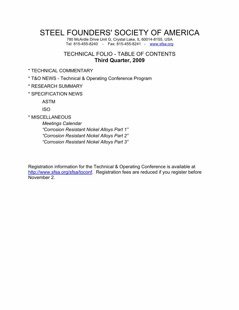
STEEL FOUNDERS' SOCIETY OF AMERICA 780 McArdle Drive Unit G, Crystal Lake, IL 60014-8155, USA Tel: 815-455-8240 - Fax: 815-455-8241 - www.sfsa.org TECHNICAL FOLIO - TABLE OF CONTENTS Third Quarter, 2009
* TECHNICAL COMMENTARY * T&O NEWS - Technical & Operating Conference Program * RESEARCH SUMMARY * SPECIFICATION NEWS ASTM
ISO * MISCELLANEOUS
Meetings Calendar “Corrosion Resistant Nickel Alloys Part 1” “Corrosion Resistant Nickel Alloys Part 2” “Corrosion Resistant Nickel Alloys Part 3”
Registration information for the Technical & Operating Conference is available at http://www.sfsa.org/sfsa/toconf. Registration fees are reduced if you register before November 2.

TECHNICAL COMMENTARY STEEL FOUNDERS’ SOCIETY OF AMERICA The National T&O Conference is drawing near. Where can you find another three-day conference totally devoted to the production of steel castings? Where could you find such a conference anywhere in the world? The answer is simple – Nowhere! Here are a series of questions that you might want to consider in determining how many people you might send to the conference; 1. What valuable opportunities are you going to pass up on that your peers are going to present? 2. How are you going to ensure that you improve your safety performance? Do you know about NFPA 70E Standard for Electrical Safety in the Workplace – what effects will it have on your operation – will it affect Arc/Air operations? 3. What do you think are the best ways to improve the performance of your employees? 4. What valuable opportunities are you going to pass up on that researchers will present? 5. Take a look at the T&O Program enclosed in this Technical Folio
If you think that your company is interested in any of the issues that will be addressed in the T&O program then you need to attend the T&O Conference!
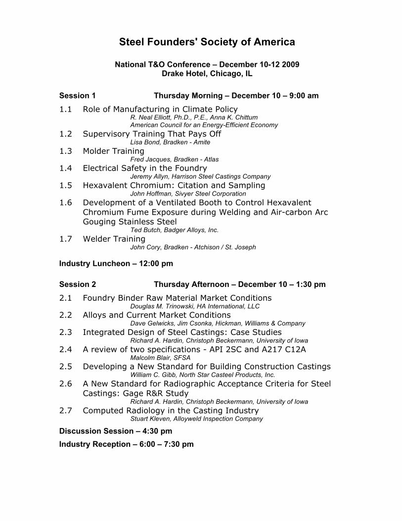
Steel Founders' Society of America
National T&O Conference – December 10-12 2009
Drake Hotel, Chicago, IL Session 1 Thursday Morning – December 10 – 9:00 am
1.1 Role of Manufacturing in Climate Policy R. Neal Elliott, Ph.D., P.E., Anna K. Chittum American Council for an Energy-Efficient Economy
1.2 Supervisory Training That Pays Off Lisa Bond, Bradken - Amite
1.3 Molder Training Fred Jacques, Bradken - Atlas 1.4 Electrical Safety in the Foundry Jeremy Allyn, Harrison Steel Castings Company 1.5 Hexavalent Chromium: Citation and Sampling John Hoffman, Sivyer Steel Corporation 1.6 Development of a Ventilated Booth to Control Hexavalent
Chromium Fume Exposure during Welding and Air-carbon Arc Gouging Stainless Steel
Ted Butch, Badger Alloys, Inc. 1.7 Welder Training John Cory, Bradken - Atchison / St. Joseph
Industry Luncheon – 12:00 pm
Session 2 Thursday Afternoon – December 10 – 1:30 pm
2.1 Foundry Binder Raw Material Market Conditions Douglas M. Trinowski, HA International, LLC 2.2 Alloys and Current Market Conditions Dave Gelwicks, Jim Csonka, Hickman, Williams & Company 2.3 Integrated Design of Steel Castings: Case Studies Richard A. Hardin, Christoph Beckermann, University of Iowa 2.4 A review of two specifications - API 2SC and A217 C12A Malcolm Blair, SFSA 2.5 Developing a New Standard for Building Construction Castings William C. Gibb, North Star Casteel Products, Inc. 2.6 A New Standard for Radiographic Acceptance Criteria for Steel
Castings: Gage R&R Study Richard A. Hardin, Christoph Beckermann, University of Iowa 2.7 Computed Radiology in the Casting Industry Stuart Kleven, Alloyweld Inspection Company
Discussion Session – 4:30 pm Industry Reception – 6:00 – 7:30 pm

Session 3 Friday Morning – December 11 – 9:00 am 3.1 Optimizing the Corrosion Performance of Welds on 6 wt% Super
Austenitic Stainless Steel Andrew Stockdale, John DuPont, Lehigh University 3.2 Lightweight Steel and P900 Castings David Van Aken, Missouri University of Science & Technology 3.3 Extending the Capabilities of High Strength Cast Stainless Steels Rachel Abrahams, Paul Lynch, Dr. Robert C. Voigt, Pennsylvania State University 3.4 Alloying and Practical Heat Treatment Approaches for Toughness
and Strength Enhancement of 17-4 PH Arpana Murthy, Von Richards, David Van Aken, Simon Lekakh 3.5 Foundry Equipment - Air-Arc Power Source Trials and Mold Wash
Drying System Robert Murillo, Pacific Steel Casting Company 3.6 Heat Treat Super Oven Nick Gerard, Bill Dudley, Lee Rabe, M E Global, Inc. 3.7 Heat Treatment Optimizations Using Non-Contact Infrared Load
Temperature Sensing Tom Karnezos, Rachel Abrahams, Dr. Robert Voigt,
Pennsylvania State University 3.8 Heat Treat Optimization Steve Klimowicz, Eagle Alloy, Inc.
Industry Luncheon – 12:00 pm
Session 4 Friday Afternoon – December 11 – 1:30 pm
4.1 Experience with the FARO ARM at Fundidora Morelia Emmanuel Valenzuela, Fundidora Morelia SA de CV 4.2 Laser Scanning Steel Castings Greg Bosel, Capture 3D 4.3 Vacuum Assisted NaSiO4 Jim Furness, Furness-Newburge, Inc. 4.4 A Method for Dryness Assessment of Mold Coatings Bob Puhakka, Alloy Casting Industries Limited 4.5 Iron Oxide in Molds and Cores for the Production of Steel Castings Raymond Monroe, SFSA 4.6 Crack Formation in Ceramic Shell During Foam Pattern Firing Von Richards, D. Kline, Simon Lekakh, C. Mahimkar, Missouri University of Science & Technology 4.7 Measurement of Elastic Modulus of PUNB Molds as a Function of
Temperature Jacob Thole, Christoph Beckermann, University of Iowa 4.8 Modeling of the Autoclave De-Waxing Process for Investment
Casting Shells Edward A. Druschitz, Dr. Preston Scarber Jr., Dr. Alan P. Druschitz, University of Alabama - Birmingham 4.9 High Temperature Physical Properties of Molding Aggregates Jerry Thiel, University of Northern Iowa
Discussion Session – 4:40 pm

Session 5 Saturday Morning – December 12 8:00 am 5.1 Improving Efficiency through Technology Brian Raub, Southern Cast Products, Inc. 5.2 A Statistical Analysis of Grinding Room Operations Andrew McMinimee, May Foundry & Machine Company 5.3 Acid V Basic (Basic Practice in the foundry) Brent Hanquist, Harrison Steel Castings Company 5.4 Prediction of Aluminum Nitride Embrittlement in Heavy Section
Steel Castings Charles Monroe, Caterpillar 5.5 Use of Automated Inclusion Analysis to Evaluate the Effects of Ladle
Treatment on Steel Cleanliness Kent Peaslee, Vintee Singh, Simon Lekakh and Edith Martinez,
Missouri University of Science & Technology 5.6 Modeling of Reoxidation Inclusion Formation in Steel Sand Casting Kent D. Carlson, Antonio Melendez, Christoph Beckermann 5.7 Surface/Near Surface Indication – Variation of Surface Indications
from Magnetic Particle and Liquid Penetrant Inspection John A. Griffin, Robin D. Foley, University of Alabama - Birmingham
Adjourn 11:30 am
Thank you for attending the 2009 National Technical and Operating Conference

STEEL FOUNDERS’ SOCIETY OF AMERICA Research Summary October 2009 In the first quarter Research Summary it was reported that the DoE funding had been cut back significantly, that situation appears to have changed quite dramatically, while we may not see the full funding for the programs, there has been a significant increase in funding for this fiscal year, consequently we expect to see much more activity on the following projects; 1. Melting Efficiency – Kent Peaslee, MS&T 2. Surface Indications – John Griffin, UAB 3. Instrumentation (Cleaning Room and Heat Treatment studies) – Frank Peters, ISU 4. Phase transformations in 6%Mo Austenitic Stainless Steels – Scott Chumbley, ISU 5. Corrosion testing of stainless steels – John Dupont, Lehigh In these summer months you will have the opportunity to hear directly from the researchers of their plans and anticipated progress. There will two meetings that will provide opportunities for you to hear updates and influence the direction of these projects. Carbon and Low Alloy Research Review – July 15/16, Schiller Park, IL High Alloy – August 26/27, Dayton, OH Make sure you take advantage of these meetings. The following is an overview of many of the research projects; Determination of the effect of radiographic indications on performance Effect of Niyama values on mechanical properties - AMC Radiographic standards are workmanship standards; they do not indicate the effect of radiographic indications on performance. The need in the steel casting industry is to produce highly efficient designs that can optimize the properties of steel. This work is designed to develop an understanding of the effect of indications on performance followed by the development of a standard which can be used by designers to optimize casting design. This will lead to lighter and more competitive steel castings. UI have been asked to develop a quantitative method for the evaluation of the effect of indication size. A draft version of a new radiographic film interpretation standard has been prepared for review, there is now an ongoing Gage R&R study to determine the reliability of interpretations using this method. CCT diagrams for DSS and Superaustenitic Stainless Steels - CMC The required heat treatment and limiting section sizes can best be indicated by examining the CCT diagrams. Unfortunately these do not exist for some of the most recently developed alloys. This work will develop these new diagrams and assist the foundry in performing effective heat treatments. These diagrams will also assist in identifying where there may be problems in a casting design. Work on CK3MCuN (254SMO) and CN3MN (AL6XN), has shown that the reactions in these grades is extremely slow. Recent work on impact properties at NIST has shown that the toughness can deteriorate considerably when these grades are not quenched from the austenitizing temperature but are cooled and held at 1600oF for an hour, this may be linked to the chicken wire cracking phenomena. Recent work has identified the existence of a very small grain boundary precipitate. Heat treating at higher temperatures for longer times has shown that the toughness can be restored. The ongoing task is to attempt to determine where the "nose" of these intermetallic formations occur to allow foundries to determine the preferred heat treatment cycle.

Instrumentation in the cleaning room and heat treatment - CMC Short cycle heat treatment brings many benefits which include – reduced fuel cost, improved process flow. The need to control cycle time by monitoring the load condition is essential to the successful implementation of short cycles. Indications are that this can be achieved indirectly and simply by monitoring the gas supply control valve. It should be borne in mind that this does not deal with the issue of temperature uniformity. Control strategies for monitoring the load indicate that 20% reductions in energy cost can be achieved. This work is being developed further and has already led some members to reduce annealing times. Trials using wireless data transfer to enable load temperatures to be monitored are being investigated. One foundry has carried out trials using this device and is close to running some heat treatment trials, the results of these trials in terms of data transmission have been shown to be successful. The fundamental problem of poor grinding efficiency i.e. poor metal removal rates utilizing hand grinders, can only be solved by some form of automation, ISU is developing a simple grinding device that will increase efficiency by removing the man. One foundry is now using the weld feeding device to measure welding utilization. Surface indications - CMC Specification of acceptable surface indications can be one of the most contentious issues between the foundry and the purchaser. This work will characterize surface indications and form an integral part of assessing the effect of indications on part performance. Plates and castings with indications are being collected and evaluated. It s apparent that the 3:1 length to width ratio is not a good measure for discriminating the difference between a crack and a round indication. The Gage R&R of inspection by magnetic particle appears to be poor, but not worse than other studies of this operation. Typical probability of detection of indications is 50%. Melting Efficiency - CMC The use of chemical fuels has been shown reduce power consumption by ~24 kWh/t on two 20 t on EAFs. Recent plant trials have demonstrated reductions in energy consumption of 5 – 10% by changing the melting practices. One member has rescheduled his melting shop, initial reports suggests that by employing a continuous melting schedule instead of single day or night arrangements the savings in power might be of the order of 20%. Corrosion Testing - CMC Some purchasers of castings are using corrosion tests as a requirement for product acceptance. The corrosion tests that are currently available have poor Gage R&R and consequently any test is more a measure of how good a laboratory is at running the tests rather than a test of the material performance. This work will examine and quantify the issues. In addition the work will also include a study of the effect of the Niyama criteria on the corrosion resistance of the 6%Mo stainless steels. The tests on wrought grades appear to be strongly influenced by passivation time and surface finish of the specimens. However, their effect on cast grades appears to be minimal, suggesting there are other factors to be considered, e.g. segregation. A recently developed heat treatment schedule has shown that cast materials can have similar corrosion resistance to their wrought counterparts. One of our members has adopted the heat treatment procedure and seen a drop in corrosion test failures from 12% to 5%.
High Strength Steels - AMC High strength steels (YS>170ksi) have been largely ignored by users and producers alike. The Department of Defense is funding a project to examine the possibility of producing high strength steels that will compete with titanium. It is anticipated that these steels will be processed conventionally and be 4 to 10 times less expensive than comparative titanium castings. Several trial heats have been prepared for testing. The development work to date has been concentrating on the development of "17-4" grades. Design Manufacture and Production of Steel Castings - Iowa This program, which is funded by the DoD, is focused on the production of new and existing castings for the US Army. The Universities of Iowa, Iowa State and Northern Iowa are being contracted by SFSA to develop designs and manufacturing processes for these castings. The first casting to be developed is for a recoilless cannon. Trials are underway on the new casting and appear to be promising although some erosion of the part is evident. Use of Solidification Simulation for Vendor Approval - MTI A significant amount of work has been completed in the development of thermo-physical data for more reliable prediction of shrinkage in the high alloy grades. Instrumented plates have been cast for grades; CD4MCuN, CD3MN, N3M, CW6MC and CN3MN. The thermo-physical data will be made available to all SFSA members free of charge. 3rd Quarter 2009

SPECIFICATION NEWS STEEL FOUNDERS’ SOCIETY OF AMERICA ASTM
A1058 - Standard Test Methods for Mechanical Testing of Steel Products - Metric This standard will be published in volumes of ASTM standards for steel. Pressure Equipment Directive (PED) - A summary of the actions and conclusions of the discussion on the relationship ASTM steel standards to the requirements of the PED has been prepared. In effect the PED has been identified as a technical barrier to trade. Regardless of any changes that are made to ASTM standards they will not be accepted as describing materials that meet the requirements of the PED. As has already been established the PED (the law of the European Community) states that the only body that can write standards is the European Community and these are the EN standards. C12A A Task Group is being organized to discuss the production of grades utilizing nitrogen as an alloying addition to ferritic grades to improve creep properties in all product forms. EPRI has assembled a significant amount of data that apparently demonstrates the need in all product forms to significantly reduce elements that tie up nitrogen. Information proposing compositional and mechanical property restrictions has been circulated to all SFSA members and the comments have been compiled as an industry response. Some of the restrictions do not appear to be too problematic. However, the proposal to reduce the Ni level to 0.20 will increase the charge material costs. One of our members has asked about a material that is used in similar applications to C12A, i.e. E911, also called GX 12CrMoWVNbN 10-1-1. On enquiry this material is not well known in Germany and has not been incorporated in any EN standard Composition limits Committee A01 has suggested that composition limits should recognize the current product analyses rather than maintain what might be considered obsolete limits. ISO Three standards are being balloted at Final Draft International level these standards are: ISO FDIS 4986 Magnetic particle inspection - Convener DIN ISO FDIS 4987 Penetrant inspection - Convener DIN ISO FDIS 10679 Cast tool steels this has been approved and the document has been
issued as a FDIS. The USA will carry out the following Review EN10213, ASTM A487 and ISO 4991 and prepare a working paper for discussion.

Review ASTM A991 will be reviewed to determine changes and additions that may be necessary to develop an ISO TS or ISO standard. Initiate the development of a table which will utilize the European and UNS numbering systems that could be used for marking the castings. The USA will provide a list of all ISO grades with their UNS numbers and Germany will provide the European numbers. The list will include the chemical composition of each grade. 3rd Quarter 2009
STEEL FOUNDERS’ SOCIETY OF AMERICA MEETINGS CALENDAR 2009 November 10 Specifications Committee meeting – Atlanta, GA December 9-12 Technical & Operating Conference – Chicago, IL

CORROSION- RESISTANT Part 1NICKEL ALLOYS Nickel alloys provide levels of corrosion resistance not possible with other alloys. This is part one of a three-part series about corrosion-resistant nickel alloys.
Paul Crook* Haynes International Inc. Kokomo, Indiana
Nickel is an ideal base for corrosion- resistant alloys. Not only is it inher- ently resistant to certain chemicals, but
also it can be highly alloyed with ele- ments known to enhance corrosion performance, such as chromium, copper, and molybdenum, while retaining its ductile face-centered cubic structure. Iron is not as accommodating; thus high levels of such elements are not possible in the stainless steels without structural instability.
In addition to commercially pure nickel, three binary alloy systems also provide exceptional cor- rosion resistance. These include nickel-chromium (Ni-Cr), nickel-copper (Ni-Cu), and nickel-molyb- denum (Ni-Mo). Chromium enhances the resist- ance of nickel to oxidizing acids by encouraging the formation of passive films. Copper is very helpful in seawater, brackish water, and reducing acids, in particular hydrofluoric. Molybdenum is extremely beneficial in all reducing acids.
This article focuses on commercially pure nickel and the three binary alloy systems. Future arti- cles will cover ternary systems and the effects on various nickel alloys of industrially important acids, bases, and salts.
Commercially pure nickel
*Member of ASM International
Several materials are sold under the guise of
Integrated gasifcation combined cycle (IGCC) power plants suck as this re- quire the application of corrosion-resistant nickel alloys. Image courtesy U.S. Dept. of Energy.
commercially pure nickel. Most contain in excess of 99% nickel, and most contain small, elemental additions to control specific properties. Many were designed for electronics, where the electrical and magnetic properties of pure nickel are crucial.
From a corrosion standpoint, the commercially pure nickels are important for two reasons.
Resistance to the caustic alkalis: They pro- vide outstanding resistance to caustic soda and caustic potash over wide ranges of concentration and temperature.
Formability: They are easy to form into com- plex shapes and have inherent resistance to mild corrosives; thus they are suitable for food pro- cessing equipment.
The nominal compositions of several commer- cially pure nickels are given in Table 1. Wrought Nickel 200 is by far the most widely used. How- ever, for applications above approximately 300°C (570°F), Nickel 201 is preferred, because it has a lower carbon content and is thus resistant to graphitization. It also has higher creep resistance than Nickel 200.
Another important commercially pure nickel is Duranickel alloy 301, which can be strength- ened by heat treatment. It was designed as an al- ternate to Nickel 200, for applications requiring
The primary attribute
of the nickel- copper Monel
alloys is resistance
to sea water
and brackish
water.
higher strength. The applications of alloy 301 in- clude plastic extrusion press parts, glass molds, and corrosion-resistant springs. The strengthening precipitate in alloy 301 is γ ' , i.e. Ni3(Al,Ti). To gen- erate this phase, alloy 301 contains significant quantities of both aluminum and titanium. For intricate components, a cast material known as CZ-100 is available. Unusually for a cast nickel alloy, it does not require an annealing treatment prior to service.
Nickel-copper Nickel and copper, neighbors in the Periodic
Table, share the same atomic structure, face-cen- tered cubic (fcc). Moreover, this structure is re- tained in all mixtures of the two elements, at all temperatures in the solid range. This is the basis for several commercially important nickel-copper and copper-nickel alloys.
This article is concerned with the nickel-copper alloys that contain approximately 30 to 45 wt% copper. These are closely associated with Special Metals Corp. Monel trademark. At the other end of the spectrum, copper alloys containing approx- imately 30 wt% nickel have been commercially successful, albeit under less aggressive conditions. In fact, these copper-nickel alloys have the best general resistance to aqueous corrosion of all the commercially important copper alloys, especially in hydrofluoric acid.
The primary attribute of the nickel-copper Monel alloys is resistance to seawater and brackish water. They are known for their resistance to bio- fouling in such environments. They also possess excellent resistance to hydrofluoric acid and mod- erate resistance to other non-oxidizing acids. They withstand cavitation erosion and are therefore ideally suited to applications in flowing water, such as propellers and pumps.
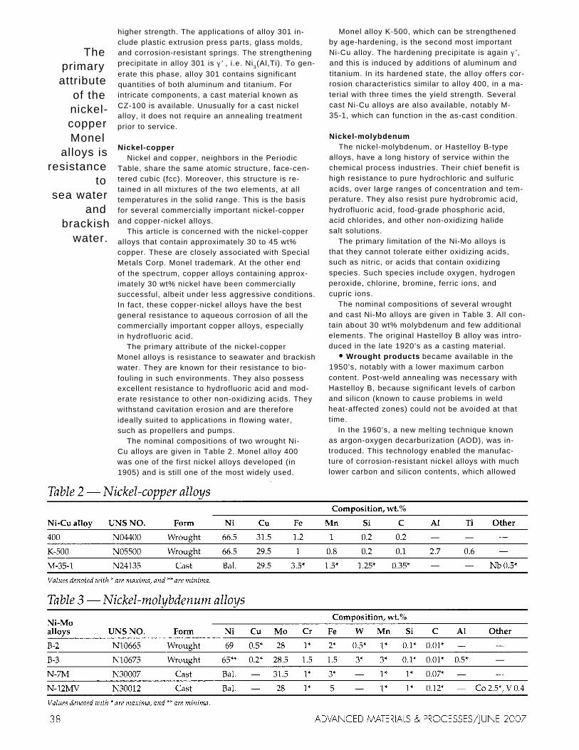
The nominal compositions of two wrought Ni- Cu alloys are given in Table 2. Monel alloy 400 was one of the first nickel alloys developed (in 1905) and is still one of the most widely used.
Monel alloy K-500, which can be strengthened by age-hardening, is the second most important Ni-Cu alloy. The hardening precipitate is again γ ’, and this is induced by additions of aluminum and titanium. In its hardened state, the alloy offers cor- rosion characteristics similar to alloy 400, in a ma- terial with three times the yield strength. Several cast Ni-Cu alloys are also available, notably M- 35-1, which can function in the as-cast condition.
Nickel-molybdenum The nickel-molybdenum, or Hastelloy B-type
alloys, have a long history of service within the chemical process industries. Their chief benefit is high resistance to pure hydrochloric and sulfuric acids, over large ranges of concentration and tem- perature. They also resist pure hydrobromic acid, hydrofluoric acid, food-grade phosphoric acid, acid chlorides, and other non-oxidizing halide salt solutions.
The primary limitation of the Ni-Mo alloys is that they cannot tolerate either oxidizing acids, such as nitric, or acids that contain oxidizing species. Such species include oxygen, hydrogen peroxide, chlorine, bromine, ferric ions, and cupric ions.
The nominal compositions of several wrought and cast Ni-Mo alloys are given in Table 3. All con- tain about 30 wt% molybdenum and few additional elements. The original Hastelloy B alloy was intro- duced in the late 1920’s as a casting material.
Wrought products became available in the 1950’s, notably with a lower maximum carbon content. Post-weld annealing was necessary with Hastelloy B, because significant levels of carbon and silicon (known to cause problems in weld heat-affected zones) could not be avoided at that time.
In the 1960’s, a new melting technique known as argon-oxygen decarburization (AOD), was in- troduced. This technology enabled the manufac- ture of corrosion-resistant nickel alloys with much lower carbon and silicon contents, which allowed
them to be safely used in the as-welded condition. Application of this melting technology led to the introduction of wrought B-2 alloy in the 1970’s, then the more stable B-3 alloy in the 1990’s.
Cast Ni-Mo alloys include only one signifi- cant development, and that is the introduction of Chlorimet 2 (more generally known as N-7M). This has a lower carbon limit than the original cast Hastelloy B alloy (the composition of which is still made under the designation N-12MV), to min- imize the precipitation of grain boundary car- bides. It has a higher molybdenum content for en- hanced corrosion resistance.
The atomic structure of the B-type alloys is pre- dominantly face-centered cubic (fcc). The alloys are supplied in the solution-annealed and water- quenched condition. The purpose of the anneal is to dissolve the majority of second phases in the microstructure, and the purpose of the quench is to “lock-in” the high temperature fcc structure. The solution annealing temperature is approxi- mately 1065°C (1950°F).
Second phases develop quickly when the B- type alloys are exposed to moderately high tem- peratures, especially in the range 650°C to 800°C (1200°F to 1470°F). Such phases reduce ductility and render the alloys susceptible to mechanical fracture (under the action of residual stress) and stress-corrosion cracking. The second phases of most concern are Ni4Mo (which forms very quickly); Ni3Mo (which requires more diffusion of molybdenum, and is therefore slower to form); M6C, and M12C. The latter two are tied to the carbon contents of the alloys. They are particu- larly damaging because they tend to form in the alloy grain boundaries.
Nickel-chromium Early experiments involving the addition of
chromium to nickel not only resulted in materials resistant to oxidizing acids, but also paved the way for the development of a wide range of oxidation- resistant high-temperature alloys. Indeed, some of the first Ni-Cr materials were, and still are, used for heating elements in domestic appliances.
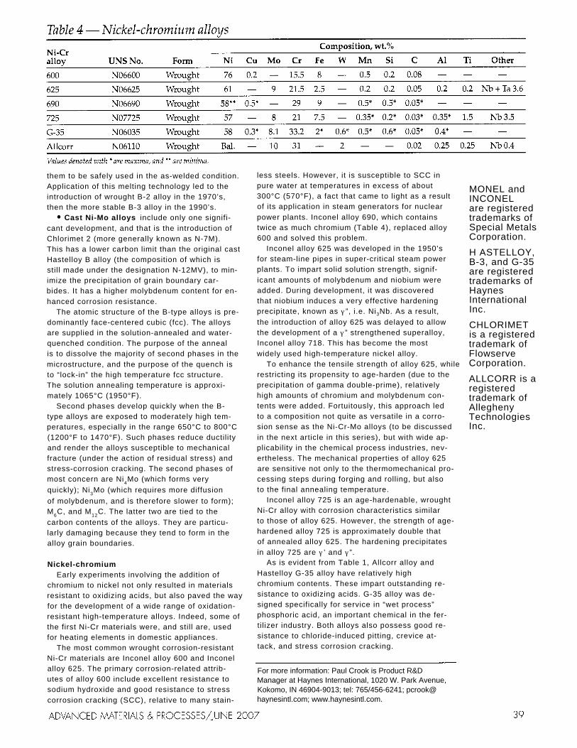
The most common wrought corrosion-resistant Ni-Cr materials are Inconel alloy 600 and Inconel alloy 625. The primary corrosion-related attrib- utes of alloy 600 include excellent resistance to sodium hydroxide and good resistance to stress corrosion cracking (SCC), relative to many stain-
less steels. However, it is susceptible to SCC in pure water at temperatures in excess of about 300°C (570°F), a fact that came to light as a result of its application in steam generators for nuclear power plants. Inconel alloy 690, which contains twice as much chromium (Table 4), replaced alloy 600 and solved this problem.
Inconel alloy 625 was developed in the 1950’s for steam-line pipes in super-critical steam power plants. To impart solid solution strength, signif- icant amounts of molybdenum and niobium were added. During development, it was discovered that niobium induces a very effective hardening precipitate, known as γ ”, i.e. Ni3Nb. As a result, the introduction of alloy 625 was delayed to allow the development of a γ ” strengthened superalloy, Inconel alloy 718. This has become the most widely used high-temperature nickel alloy.
To enhance the tensile strength of alloy 625, while restricting its propensity to age-harden (due to the precipitation of gamma double-prime), relatively high amounts of chromium and molybdenum con- tents were added. Fortuitously, this approach led to a composition not quite as versatile in a corro- sion sense as the Ni-Cr-Mo alloys (to be discussed in the next article in this series), but with wide ap- plicability in the chemical process industries, nev- ertheless. The mechanical properties of alloy 625 are sensitive not only to the thermomechanical pro- cessing steps during forging and rolling, but also to the final annealing temperature.
Inconel alloy 725 is an age-hardenable, wrought Ni-Cr alloy with corrosion characteristics similar to those of alloy 625. However, the strength of age- hardened alloy 725 is approximately double that of annealed alloy 625. The hardening precipitates in alloy 725 are γ ’ and γ ”.
As is evident from Table 1, Allcorr alloy and Hastelloy G-35 alloy have relatively high chromium contents. These impart outstanding re- sistance to oxidizing acids. G-35 alloy was de- signed specifically for service in “wet process” phosphoric acid, an important chemical in the fer- tilizer industry. Both alloys also possess good re- sistance to chloride-induced pitting, crevice at- tack, and stress corrosion cracking.
For more information: Paul Crook is Product R&D Manager at Haynes International, 1020 W. Park Avenue, Kokomo, IN 46904-9013; tel: 765/456-6241; pcrook@ haynesintl.com; www.haynesintl.com.
MONEL and INCONEL are registered trademarks of Special Metals Corporation. H ASTELLOY, B-3, and G-35 are registered trademarks of Haynes International Inc. CHLORIMET is a registered trademark of Flowserve Corporation. ALLCORR is a registered trademark of Allegheny Technologies Inc.
CORROSION- RESISTANT PART 2
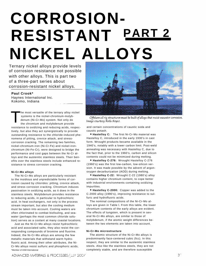
NICKEL ALLOYS Ternary nickel alloys provide levels of corrosion resistance not possible with other alloys. This is part two of a three-part series about corrosion-resistant nickel alloys.
Paul Crook* Haynes International Inc. Kokomo, Indiana
he most versatile of the ternary alloy nickel systems is the nickel-chromium-molyb- denum (Ni-Cr-Mo) system. Not only do Tthe chromium and molybdenum provide
resistance to oxidizing and reducing acids, respec- tively, but also they act synergistically to provide outstanding resistance to the chloride-induced phe- nomena of pitting, crevice attack, and stress- corrosion cracking. The remaining two families, nickel-chromium-iron (Ni-Cr-Fe) and nickel-iron- chromium (Ni-Fe-Cr), were designed to bridge the performance and cost gaps between the Ni-Cr al- loys and the austenitic stainless steels. Their ben- efits over the stainless steels include enhanced re- sistance to stress corrosion cracking.
Ni-Cr-Mo alloys The Ni-Cr-Mo alloys are particularly resistant
to the insidious and unpredictable forms of cor- rosion caused by chlorides: pitting, crevice attack, and stress corrosion cracking. Chromium induces passivation in oxidizing acids, as it does in the stainless steels. Molybdenum provides resistance to reducing acids, in particular to hydrochloric acid. In heat exchangers, not only is the process stream important, but also the cooling medium must be taken into account. Cooling waters are often chlorinated to combat biofouling, and sea- water (perhaps the most common chloride solu- tion) serves as a coolant at many coastal locations.
Just as the Ni-Cr-Mo alloys resist hydrochloric acid and associated salts, they also resist the cor- responding compounds of bromine and fluorine. Indeed, the Ni-Cr-Mo alloys are among the few metallic materials that withstand warm hydro- fluoric acid. Among their other attributes, the Ni- Cr-Mo alloys resist sulfuric and phosphoric acids, *Member of ASM lnternational
and certain concentrations of caustic soda and caustic potash.
Hastelloy C: The first Ni-Cr-Mo material was Hastelloy C, introduced in the early 1930’s in cast form. Wrought products became available in the 1940’s, notably with a lower carbon limit. Post-weld annealing was necessary with Hastelloy C, due to the fact that, prior to the 1960’s, carbon and silicon contents could not be minimized during melting.
Hastelloy C-276: Wrought Hastelloy C-276 (1960’s) was the first low-carbon, low-silicon ver- sion. It was made possible by the advent of argon- oxygen decarburization (AOD) during melting.
Hastelloy C-22: Wrought C-22 (1980’s) alloy contains higher chromium content, to cope better with industrial environments containing oxidizing impurities.
Hastelloy C-2000: Copper was added to the C-2000 alloy (1990’s), improving resistance to sul- furic and hydrofluoric acids.
The nominal compositions of the Ni-Cr-Mo al- loys are given in Table l. From this table, the lower chromium contents of the early alloys are evident. The effects of tungsten, which is present in sev- eral Ni-Cr-Mo alloys, are similar to those of molybdenum, if the atomic weight differences be- tween the two elements are taken into account.
Ni-Cr-Mo microstructure The atomic structure of the Ni-Cr-Mo alloys is
predominantly face-centered cubic (fcc). In this respect, they are similar to the austenitic stainless steels. Also like the stainless steels, they are not completely stable, and are therefore susceptible

to the formation of second phases when exposed to temperatures in the approximate range 650 to 1100°C (the sensitizing range).
The Ni-Cr-Mo alloys are normally supplied in the solution-annealed condition; the annealing temperature for most alloys is about 1120°C. They are typically quenched in water from their an- nealing temperatures, to "lock in" their high tem- perature fcc microstructures. However, they are quenched in gas if they are annealed in hydrogen.
Concerns over structural instability are greatest during welding, since weld heat-affected zones (HAZ) are exposed to temperatures in the sensi- tizing range. The second phases of most concern are M6C carbides, which develop in the range 650 to 1040°C, and µ (mu) phase, which occurs in the range 760 to 1090°C. Both of these phases form rapidly and heterogeneously, typically within the alloy grain boundaries, rendering them suscep- tible to preferential attack.
At lower temperatures, a homogeneous, long- range ordering reaction is possible, but this is slow and of no concern during welding. That said, Hastelloy C-22HS alloy was designed specifically to take advantage of the long-range ordering re- action. Its yield strength can be doubled by this reaction, in a period of 48 hours, with only a mod- erate reduction in its corrosion performance.
The development of cast Ni-Cr-Mo alloys has
followed a similar path, with initial efforts aimed at improving thermal stability, and, where pos- sible, enhanced corrosion resistance. Notable among early developments was Chlorimet 3, which is also known as CW-6M. Apart from Hastelloy C alloy, the composition of which is still sold as CW-12MW, and Chlorimet 3, only two other casting alloys have found commercial suc- cess, namely CW-2M (a cast counterpart to wrought C-4 alloy) and CX-2MW (a cast counter- part to wrought C-22 alloy).
Although undesirable from a thermal stability standpoint, silicon is important in casting alloys, since it influences fluidity. Silicon maxima are therefore much greater in Ni-Cr-Mo casting com- positions. Higher carbon contents are also common in castings, unless special precautions are taken to avoid its pickup. Along with slow cooling from the molten state, a necessary result of pouring such materials into ceramic molds, these factors result in significant grain boundary precipitation, which must be dissolved by solu- tion annealing if optimum corrosion properties are to be attained.
Ni-Cr-Fe alloys The nickel-chromium-iron alloys were origi-
nally designed to fill the performance gap between the high-molybdenum stainless steels and the

nickel-chromium-molybdenum alloys. Thus, they possess good resistance to chloride-induced phe- nomena, such as pitting, crevice corrosion, and stress corrosion cracking, and exhibit moderate resistance to the halogen acids, in particular hy- drochloric. Significant applications of the Ni-Cr- Fe alloys include oil and gas well tubes and evap- orators for the concentration of fertilizer-grade phosphoric acid.
Nominal compositions of three such alloys are given in Table 2. These evolved from Hastelloy G alloy developed in the 1950’s before the advent of argon-oxygen decarburization (AOD). Applica- tion of this melting technology allowed the intro- duction, in the 1970’s, of Hastelloy G-3 alloy, which became established in two major applications. First, cold-reduced tubes of G-3 alloy became standard for moderately sour oil and gas wells. Second, G- 3 alloy was applied in evaporators for concentrating fertilizef-grade phosphoric acid.
The success of the G-3 alloy in these applications led, in the 1980’s, to the introduction of the G-30 and G-50 alloys. The G-30 alloy was a high- chromium variant with enhanced resistance to phosphoric acid. G-50 was a high-molybdenum variant with enhanced resistance to stress corro- sion cracking in elevated temperature environ- ments containing hydrogen sulfide, such as those in oil and gas wells. Notable in Table 2 are the rel- atively high chromium content of G-30 alloy and the relatively high molybdenum content of G-50 alloy. It should also be noted that G-3 and G-30
alloys contain copper, to enhance their resistance to sulfuric and hydrofluoric acids. Incidentally, the original G alloy was conceived as a copper-bearing variant of a prior Ni-Cr-Fe alloy, Hastelloy F.
Ni-Fe-Cr alloys Incoloy alloy 825 and its age-hardenable cousin
Incoloy alloy 925 contain significantly more iron than chromium, and thus constitute a separate grouping, shown in Table 3. With iron contents of 30 and 28 wt% respectively, they are composition- ally close to the high-nickel austenitic stainless steels. The negative aspects of such high iron con- tents are reduced solubilities of key elements such as molybdenum, and reduced resistance to envi- ronmental cracking. On the other hand, high iron contents reduce the cost of making the alloys.
One of the main applications of 825 alloy is downhole tubing in the oil and gas industries. It is a common material for wells that are only mod- erately sour. For wells with higher hydrogen sul- fide contents, Ni-Cr-Fe and (in extreme cases) Ni- Cr-Mo materials (G-3, G-50, and C-276 alloys, in particular) are more suitable.
One of the key additions to alloy 825 is copper. As in other materials, it provides enhanced resist- ance to sulfuric acid.
For more information: Paul Crook is Product R&D Manager at Haynes International, 1020 W. Park Avenue, Kokomo, IN 46904-9013; tel: 765/456-6241; pcrook@ haynesintl.com; www.haynesintl.com.
Incoloy is a registered trademark of Special Metals Corporation. Hastelloy, C-22, C-22HS, C-2000, G-30, and G-50 are registered trademarks of Haynes International, Inc. Chlorimet is a registered trademark of Flowserve Corporation.

CORROSION- RESISTANT PART 3
NICKEL ALLOYS Nickel alloys provide levels of corrosion resistance not possible with other alloys. This is part three of a four-part series about corrosion-resistant nickel alloys.
Paul Crook*Haynes International Inc. Kokomo, Indiana
he corrosion-resistant nickel alloys are vitally important industrial materials. In most aggressive environments, they rep- T resent a significant improvement over
the stainless steels, and their higher initial costs are offset by longer life, hence reduced equipment downtime. They are also easy to form and weld into complex industrial components.
This article describes nickel alloy corrosion be- havior in sea water and various salt solutions, as well as hydrochloric, hydrobromic, and hydro- fluoric acids. Where sufficient data are available, 0.1 mm/y line charts provide comparisons with the stainless steels. To define the resistance of some of the nickel alloys to chloride-induced pitting and crevice attack, their Critical Pitting Temper- atures (CPT's) and Critical Crevice Temperatures (CCT's) in acidified ferric chloride are given, alongside those for some of the more common stainless steels. To complement these data, previ- ously published information on the crevice cor- rosion resistance of the same alloys in seawater are provided. To demonstrate the relative resist- ance of the nickel alloys and stainless steels to stress corrosion cracking (SCC), test results for U- bend samples in boiling magnesium chloride are given.
Next month's final article in the series will cover nickel alloy performance in sulfuric, phosphoric, and nitric acids. The welding and fabrication char- acteristics of the corrosion-resistant nickel alloys will be discussed, and some of their uses within the chemical process industries will be defined.
Sea water Sea water is encountered by marine vessels, oil
rigs, and coastal structures and facilities (which typically use sea water as a coolant). As a chlo- *Member of ASM lnternational
ride, it can induce pitting, crevice attack, and stress corrosion cracking of metallic materials, as well as uniform attack. Furthermore, marine equip- ment can become encrusted, leading to a form of crevice attack known as "under-deposit" cor- rosion. Biofouling is also an issue in sea water.
Fortunately, the nickel alloys possess good sea water resistance. In particular, those with high copper contents, such as alloy 400, resist bio- fouling (copper is a poison to microbes). For stag- nant or low-velocity conditions, chromium- and molybdenum-bearing nickel alloys provide higher resistance to pitting and crevice attack.
Some recent crevice corrosion data for seawater, generated as part of a U.S. Navy study at the LaQue Laboratories in Wrightsville Beach, North Carolina, are presented in Table 1. Crevice tests were carried out in both still (quiescent) and flowing seawater, at 29°C, plus or minus 3°C. Two samples of each alloy were tested in still water for 180 days, and two samples of each alloy were tested in flowing water for 180 days. Each sample contained two possible crevice sites. In quiescent seawater, the results mirror those generated in acidified ferric chloride, with C-22 and C-2000 al- loys as the most resistant. In flowing seawater, crevice attack of the stainless steels was shallower, and none of the Ni-Cr-Mo alloys exhibited crevice corrosion.
Salt solutions Although many salts cause few problems for

nickel alloys, some can induce insidious and un- predictable forms of attack. For example, water solutions of chloride salts are known to cause pit- ting, crevice attack, and stress-corrosion cracking of stainless steels in particular. Other halide salts (notably bromides and fluorides) induce similar effects.
Not only anions are of concern when salts are present in aqueous systems, but also cations can
be influential. For example, ferric ions and cupric ions can substantially alter the electrochemistry of acid systems, resulting in cathodic reactions of higher potential, and significant corrosion of al- loys that would otherwise be inert. The Ni-Cu and Ni-Mo materials are particularly susceptible to such effects.
Fortunately, the nickel alloys in general are very resistant to chloride-induced stress corrosion cracking and some (notably the Ni-Cr-Mo ma- terials) possess high resistance to pitting and crevice attack. In fact, much of their success in chemical in- dustry applications is due to these attributes.
To assess the resistance of alloys to crevice at- tack and pitting, it is customary to measure their Critical Crevice Temperatures (CCT’s) and Crit- ical Pitting Temperatures (CPT’s) in acidified 6 wt% ferric chloride, in accordance with the pro- cedures defined in ASTM Standard G 48. These values represent the lowest temperatures at which crevice attack and pitting are encountered in acid- ified ferric chloride in a 72-hour time frame. CCT and CPT values for several nickel alloys and stain- less steels are given in Table 2. These data clearly show the superiority of the chromium-bearing nickel alloys over the stainless steels.
A common solution for evaluating the resist- ance to chloride-induced stress corrosion cracking of metallic materials is boiling 45 wt.% magne- sium chloride. Typically, U-bend samples are tested in this environment for periods up to 1008 hours, with interruptions to check for cracking. Data for several nickel alloys and stainless steels are presented in Table 3. The table shows that low- iron nickel alloys, such as the Ni-Cr-Mo materials, offer the highest resistance to stress corrosion cracking.
Hydrobromic acid Hydrobromic is one of the strongest mineral
acids. Indeed, it is a more effective solvent for some ore minerals than hydrochloric acid because of its higher boiling point and stronger reducing action. One of the primary functions of hydro- bromic acid is for the production of inorganic bro- mides for applications such as some medicines, adhesives, and photosensitive emulsions.
Of the nickel alloys, those with high molyb- denum contents possess the highest resistance to hydrobromic and the other halogen acids. Iso- corrosion diagrams for B-3 and C-2000 alloys (as representatives of the Ni-Mo and Ni-Cr-Mo groups) are shown in Figures 1 and 2, respectively.

Figure 1 indicates that B-3 alloy can function up to the boiling-point curve in hydrobromic acid, although corrosion rates in excess of 0.1 mm/y are expected at temperatures above about 40°C (100°F). The diagram for C-2000 alloy is quite dif- ferent. On a positive note, corrosion rates of less than 0.1 mm/y (the accepted limit for thin struc- tures) are expected over a larger range. On the other hand, rates over 0.5 mm/y (the accepted limit for thick structures) are anticipated within a significant area below the boiling-point curve.
These diagrams were created by analyzing nu- merous corrosion rates generated in pure hydro- bromic acid in the laboratory. With regard to the impurities and residuals often present in indus- trial process streams, if these are of an oxidizing nature, then they are detrimental to the Ni-Mo materials. The Ni-Cr-Mo alloys, on the other hand, are tolerant of species of an oxidizing nature, and even benefit from them. Such species include ferric ions, cupric ions, oxygen, chlorine, and hydrogen peroxide.
Hydrochloric acid Hydrochloric acid is by far the most important
chemical for corrosion-resistant nickel alloys in the chemical process industries. Not only is it widely encountered, but also it is very aggressive to the stainless steels. Furthermore, hydrochloric acid is indirectly responsible for the insidious ef- fects of chloride salts on metallic materials.
Iso-corrosion diagrams for alloys representing
the Ni-Mo, Ni-Cu, Ni-Cr, and Ni-Cr-Mo groups are shown in Figures 3 to 6. Figure 3 indicates that the Ni-Mo alloys can function in 0 to 20 wt% hy- drochloric acid up to the boiling-point curve, without the corrosion rates exceeding 0.5 mm/y. Indeed, rates of 0.3 mm/y or less are typical above 40°C (100°F).
The Ni-Cr-Mo alloys are the next best option for hydrochloric acid, service, and are preferred at low concentrations and elevated temperatures. High-molybdenum Ni-Cr alloys, such as alloy 625 (Figure 6) also offer considerable resistance to hy- drochloric acid.
For perspective, a comparison between the per- formance of the Ni-Cr-Mo materials (represented by C-2000 alloy) and three types of austenitic stain- less steel is given in Figure 7. This indicates the concentration/temperature combinations at which a corrosion rate of 0.1 mm/y would be expected, based on lab- oratory tests in hy- drochloric acid. Not surprisingly, the stain- less steel with the highest molybdenum content (254SMO alloy) is the most resistant of the stainless steels. However, this falls well short of the C-2000 alloy.
Hydrofluoric Acid Hydrofluoric acid is a water so-
lution of hydrogen fluoride. It is important in many chemical processes, notably those in- volved with the production of refrigerants, adhesives, and flu- oropolymers (such as PTFE). It also works to pickle various metallic materials and to etch glass. More important, it is used for the acid treatment of oil wells and the alkylation of petroleum products.
Hydrofluoric acid is among the most dangerous of chemicals, as it is highly corrosive to skin and mucous membranes. Contain- ment of the acid is also a problem, especially at elevated temperatures and intermediate concentrations. The reactive metals (notably titanium, zirco- nium, niobium, and tantalum), for example, are readily attacked by hydrofluoric acid, and the stainless steels generally exhibit high corrosion rates.
Fortunately, the nickel alloys exhibit low to moderate corro- sion rates in hydrofluoric acid, over wide ranges of concentra-
tion and temperature, and are thus suitable for many types of equipment involved in the manu- facture and application of the acid. It is believed that the resistance of the nickel alloys to hydro- fluoric acid is due, in part, to the formation of pro- tective surface films, in particular nickel fluoride.
The laboratory characterization of the nickel al- loys in hydrofluoric acid has not been as exten- sive as it has with other common inorganic acids, largely because of its dangerous nature. The lim- ited amount of information available, however, suggests the following:
Monel alloy 400 and Hastelloy C-2000 alloy are among the most resistant. Alloy 400 is most suitable when fully immersed; C-2000 alloy ex- cels in vapor spaces above warm hydrofluoric acid solutions.
In hydrofluoric acid laboratory tests, the du-
ration of testing is important. This probably re- lates to the time it takes for protective fluoride films to form on the different alloys.
The nickel alloys are susceptible to stress cor- rosion cracking in hydrofluoric acid, and (in some cases) in the associated vapor spaces. Therefore, care should taken to avoid applied or residual stresses in nickel alloy components exposed to the chemical.
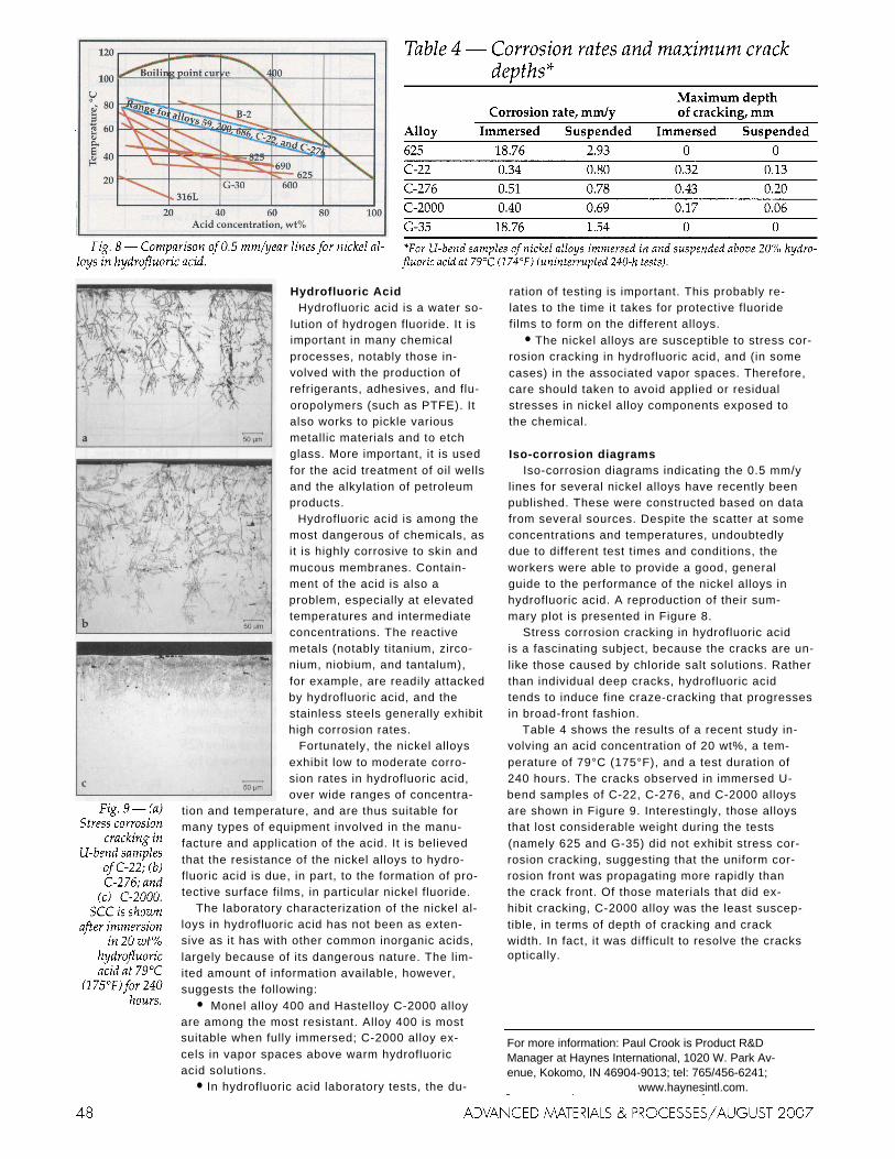
Iso-corrosion diagrams Iso-corrosion diagrams indicating the 0.5 mm/y
lines for several nickel alloys have recently been published. These were constructed based on data from several sources. Despite the scatter at some concentrations and temperatures, undoubtedly due to different test times and conditions, the workers were able to provide a good, general guide to the performance of the nickel alloys in hydrofluoric acid. A reproduction of their sum- mary plot is presented in Figure 8.
Stress corrosion cracking in hydrofluoric acid is a fascinating subject, because the cracks are un- like those caused by chloride salt solutions. Rather than individual deep cracks, hydrofluoric acid tends to induce fine craze-cracking that progresses in broad-front fashion.
Table 4 shows the results of a recent study in- volving an acid concentration of 20 wt%, a tem- perature of 79°C (175°F), and a test duration of 240 hours. The cracks observed in immersed U- bend samples of C-22, C-276, and C-2000 alloys are shown in Figure 9. Interestingly, those alloys that lost considerable weight during the tests (namely 625 and G-35) did not exhibit stress cor- rosion cracking, suggesting that the uniform cor- rosion front was propagating more rapidly than the crack front. Of those materials that did ex- hibit cracking, C-2000 alloy was the least suscep- tible, in terms of depth of cracking and crack width. In fact, it was difficult to resolve the cracks optically.
For more information: Paul Crook is Product R&D Manager at Haynes International, 1020 W. Park Av- enue, Kokomo, IN 46904-9013; tel: 765/456-6241; [email protected]; www.haynesintl.com.