Embed Size (px)
Citation preview
BRITISH STANDARD
BS EN 10080:2005Steel for the reinforcement of concrete — Weldable reinforcing steel — General
The European Standard EN 10080:2005 has the status of a British Standard
ICS 77.140.15; 77.140.60; 77.140.65
�������������� ���������������������������������������������������
BS EN 10080:2005
This British Standard was published under the authority of the Standards Policy and Strategy Committee on 23 December 2005
© BSI 23 December 2005
ISBN 0 580 46804 6
National foreword
This British Standard is the official English language version of EN 10080:2005 but will not become current until 01 January 2006.EN 10080 is a candidate ‘‘harmonized’’ European Standard and fully takes into account the requirements of the European Commission mandate M115, [Reinforcing and prestressing steel (for concrete)], given under the EU Construction Products Directive (89/106/EEC), and is intended to lead to CE marking. The date of applicability of EN 10080 as a ‘‘harmonized’’ European Standard, i.e. the date after which this standard may be used for CE marking purposes, is subject to an announcement in the Official Journal of the European Communities.The Commission in consultation with Member States has agreed a transition period for the co-existence of ‘‘harmonized’’ European Standards and their corresponding national standard(s). It is intended that this period will comprise a period, usually nine months, after the date of availability of the European Standard, during which any required changes to national regulations are to be made, followed by a further period, usually of 12 months, for the implementation of CE marking. At the end of this co-existence period, conflicting national standard(s) will be withdrawn.EN 10080 does not include all the requirements to fully specify reinforcing steels. It is intended that EN 10080 should be used in conjunction with a Technical Specification, in which the details of the performance characteristics are specified. Within the UK, three standards have been revised for use with EN 10080, these are:— BS 4449:2005, Steel for the reinforcement of concrete — Weldable
reinforcing steel — Bar, coil and decoiled product — Specification— BS 4482:2005, Steel wire for the reinforcement of concrete products —
Specification— BS 4483:2005, Steel fabric for the reinforcement of concrete — Specification
EN 10080:2005 is the subject of transitional arrangements agreed under the Commission mandate. The above standards contain some requirements, which conflict with EN 10080:2005. Based on the transition period of twenty-one months, these standards will be further revised by October 2007, so that they do not conflict with EN 10080.NOTE This date is approximate. Users of this standard should contact BSI Customer Services for confirmation of revisions.
Summary of pages
This document comprises a front cover, an inside front cover, page i, a blank page, the EN title page, pages 2 to 69 and a back cover.
The BSI copyright notice displayed in this document indicates when the document was last issued.
Amendments issued since publication
Amd. No. Date Comments
BS EN 10080:2005
The UK participation in its preparation was entrusted by Technical Committee ISE/9, Steel for concrete reinforcement, to Subcommittee ISE/9/1, Bars, wire and fabric for concrete reinforcement, which has the responsibility to:
A list of organizations represented on this committee can be obtained on request to its secretary.
If CE marking is performed, the procedures in Annex ZA will apply. The significance of the CE marking is that the product manufacturer claims compliance with the ‘‘harmonized’’ requirements given in the normative text of the product standard. These relate to the essential requirements of the EU Construction Products Directive. Not all product characteristics need necessarily be given on the CE marking, but those product characteristics covered by regulations in force in each EU Member State, where the manufacturer intends that the product will be used, do need to be stated.
Cross-references
The British Standards which implement international or European publications referred to in this document may be found in the BSI Catalogue under the section entitled “International Standards Correspondence Index”, or by using the “Search” facility of the BSI Electronic Catalogue or of British Standards Online.
This publication does not purport to include all the necessary provisions of a contract. Users are responsible for its correct application.
— aid enquirers to understand the text;
— present to the responsible international/European committee any enquiries on the interpretation, or proposals for change, and keep UK interests informed;
— monitor related international and European developments and promulgate them in the UK.
i

blank
www.bzfxw.com
EUROPEAN STANDARD
NORME EUROPÉENNE
EUROPÄISCHE NORM
EN 10080
May 2005
ICS 77.140.15; 77.140.60; 77.140.65 Supersedes ENV 10080:1995
English version
Steel for the reinforcement of concrete - Weldable reinforcing steel - General
Aciers pour l'armature du béton - Aciers soudables pour béton armé - Généralités
Stahl für die Bewehrung von Beton - Schweißgeeigneter Betonstahl - Allgemeines
This European Standard was approved by CEN on 21 April 2005. CEN members are bound to comply with the CEN/CENELEC Internal Regulations which stipulate the conditions for giving this European Standard the status of a national standard without any alteration. Up-to-date lists and bibliographical references concerning such national standards may be obtained on application to the Central Secretariat or to any CEN member. This European Standard exists in three official versions (English, French, German). A version in any other language made by translation under the responsibility of a CEN member into its own language and notified to the Central Secretariat has the same status as the official versions. CEN members are the national standards bodies of Austria, Belgium, Cyprus, Czech Republic, Denmark, Estonia, Finland, France, Germany, Greece, Hungary, Iceland, Ireland, Italy, Latvia, Lithuania, Luxembourg, Malta, Netherlands, Norway, Poland, Portugal, Slovakia, Slovenia, Spain, Sweden, Switzerland and United Kingdom.
EUROPEAN COMMITTEE FOR STANDARDIZATION C O M I T É E U R O P É E N D E N O R M A L I S A T I O N E U R O P Ä I S C H E S K O M I T E E F Ü R N O R M U N G
Management Centre: rue de Stassart, 36 B-1050 Brussels
© 2005 CEN All rights of exploitation in any form and by any means reserved worldwide for CEN national Members.
Ref. No. EN 10080:2005: E
www.bzfxw.com
EN 10080:2005 (E)
2
Contents
Page
Foreword ..................................................................................................................................................................3 1 Scope ...........................................................................................................................................................4 2 Normative references .................................................................................................................................4 3 Terms and definitions.................................................................................................................................5 4 Symbols.......................................................................................................................................................8 5 Designation ...............................................................................................................................................10 5.1 Bar, coil and de-coiled product................................................................................................................10 5.2 Welded fabric ............................................................................................................................................10 5.3 Lattice girders ...........................................................................................................................................12 6 Steelmaking and manufacturing processes ...........................................................................................13 7 Performance characteristics ....................................................................................................................13 7.1 Weldability and chemical composition ...................................................................................................13 7.2 Mechanical properties ..............................................................................................................................14 7.3 Dimensions, mass and tolerances...........................................................................................................17 7.4 Bond strength and surface geometry......................................................................................................20 7.5 Verification of performance characteristics............................................................................................22 8 Evaluation of conformity ..........................................................................................................................22 8.1 Factory production control ......................................................................................................................22 8.2 Initial type testing......................................................................................................................................25 8.3 Continuous surveillance of factory production control and audit testing............................................28 8.4 Evaluation, reporting and action..............................................................................................................30 8.5 Assessment of the long term quality level..............................................................................................31 9 Test methods.............................................................................................................................................32 9.1 Bars, coils and de-coiled products..........................................................................................................32 9.2 Welded fabric ............................................................................................................................................32 9.3 Lattice girders ...........................................................................................................................................33 10 Identification of the manufacturer and the technical class....................................................................33 10.1 Bar..............................................................................................................................................................33 10.2 Coil .............................................................................................................................................................35 10.3 De-coiled product......................................................................................................................................36 10.4 Welded fabric ............................................................................................................................................36 10.5 Lattice girders ...........................................................................................................................................36 11 Verification of mechanical properties in the case of dispute ................................................................36 Annex A (informative) Examples of weld points in lattice girder joints ...........................................................37 Annex B (normative) Test methods for lattice girders........................................................................................38 Annex C (informative) Bond test for ribbed and indented reinforcing steel – Beam test ...............................44 Annex D (informative) Bond test for ribbed and indented reinforcing steel – Pull-out test............................54 Annex E (informative) Comparison of symbols used in this European Standard with those used in EN
1992-1-1 and EN 1992-1-2 .........................................................................................................................61 Annex ZA (informative) Clauses of this European Standard addressing the provisions of the EU
Construction Products Directive .............................................................................................................62
www.bzfxw.com
EN 10080:2005 (E)
3
Foreword
This document (EN 10080:2005) has been prepared by Technical Committee ECISS/TC 19 “Concrete reinforcing and pre-stressing steels - Properties, dimensions, tolerances and specific tests”, the secretariat of which is held by DIN.
This European Standard shall be given the status of a national standard, either by publication of an identical text or by endorsement, at the latest by November 2005, and conflicting national standards shall be withdrawn at the latest by May 2007.
This document has been prepared under Mandate M/115 given to CEN by the European Commission and the European Free Trade Association and supports essential requirements of the EU Construction Products Directive (89/106/EEC).
For relationship with the EU Construction Products Directive, see informative Annex ZA, which is an integral part of this document.
This document does not apply to non-weldable reinforcing steel.
This document does not define technical classes. Technical classes should be defined in accordance with this document by specified values for Re, Agt, Rm/Re, Re,act./Re,nom. (if applicable), fatigue strength (if required), bendability, weldability, bond strength, strength of welded or clamped joints (for welded fabric or lattice girders) and tolerances on dimensions.
According to the CEN/CENELEC Internal Regulations, the national standards organizations of the following countries are bound to implement this European Standard: Austria, Belgium, Cyprus, Czech Republic, Denmark, Estonia, Finland, France, Germany, Greece, Hungary, Iceland, Ireland, Italy, Latvia, Lithuania, Luxembourg, Malta, Netherlands, Norway, Poland, Portugal, Slovakia, Slovenia, Spain, Sweden, Switzerland and United Kingdom.
www.bzfxw.com
EN 10080:2005 (E)
4
1 Scope
1.1 This European Standard specifies general requirements and definitions for the performance characteristics of weldable reinforcing steel used for the reinforcement of concrete structures, delivered as finished products in the form of:
bars, coils (rod, wire) and de-coiled products;
sheets of factory-made machine-welded fabric;
lattice girders.
1.2 Steels according to this European Standard have a ribbed, indented or smooth surface.
1.3 This European Standard does not apply to:
non-weldable reinforcing steel;
galvanized reinforcing steel;
epoxy-coated reinforcing steel;
corrosion resistant reinforcing steel;
prestressing steels (see prEN 10138-1 to -4);
indented strip;
further processing, e.g. cutting or cutting and bending.
2 Normative references
The following referenced documents are indispensable for the application of this document. For dated references, only the edition cited applies. For undated references, the latest edition of the referenced document (including any amendments) applies.
EN 10020:2000, Definition and classification of grades of steel
EN 10079:1992, Definition of steel products
EN ISO 377, Steel and steel products — Location and preparation of samples and test pieces for mechanical testing (ISO 377:1997)
EN ISO 7500-1, Metallic materials — Verification of static uniaxial testing machines — Part 1: Tension / compression testing machines — Verification and calibration of the force-measuring system (ISO 7500-1:2004)
EN ISO 15630-1, Steel for the reinforcement and prestressing of concrete — Test methods — Part 1: Reinforcing bars, wire rod and wires (ISO 15630-1:2002)
EN ISO 15630-2, Steel for the reinforcement and prestressing of concrete — Test methods — Part 2: Welded fabric (ISO15630-2:2002)
NOTE See also C.2 and D.2.
www.bzfxw.com
EN 10080:2005 (E)
5
3 Terms and definitions
For the purposes of this European Standard, the terms and definitions given in EN 10020:2000 and EN 10079:1992 and the following apply.
3.1 reinforcing steel steel product with a circular or practically circular cross-section which is suitable for the reinforcement of concrete
3.2 ribbed reinforcing steel reinforcing steel with at least two rows of transverse ribs, which are uniformly distributed over the entire length
3.3 longitudinal rib uniform continuous protrusion parallel to the axis of the bar, rod or wire
3.4 transverse rib any rib on the surface of the bar, rod or wire other than a longitudinal rib
3.5 rib height, h distance from the highest point of the rib (transverse or longitudinal) to the surface of the core, to be measured normal to the axis of the bar, rod or wire
3.6 rib or indentation spacing, c distance between the centres of two consecutive transverse ribs or two consecutive indentations measured parallel to the axis of the bar, rod or wire
3.7 angle of transverse rib or indentation inclination, ß angle between the axis of the transverse rib or indentation and the longitudinal axis of the bar, rod or wire
3.8 transverse rib flank inclination, αααα angle of the rib flank measured perpendicular to the longitudinal axis of the rib
3.9 relative rib area, fR area of the projection of all ribs on a plane perpendicular to the longitudinal axis of the bar, rod or wire, divided by the rib spacing and the nominal circumference
3.10 indented reinforcing steel reinforcing steel with defined indentations uniformly distributed over the entire length
3.11 indentation depth, t distance between the surface of the wire and the deepest point of the indentation
3.12 indentation width, b width of the indention to be measured parallel to the axis of the bar, rod or wire
3.13 plain reinforcing steel reinforcing steel with a smooth surface
www.bzfxw.com
EN 10080:2005 (E)
6
3.14 coil single length of reinforcing steel (usually rod or wire) wound in concentric rings
3.15 de-coiled product reinforcing steel manufactured in coils and subsequently straightened for further processing
3.16 nominal cross-sectional area, An
cross-sectional area equivalent to the area of a circular plain bar of the same nominal diameter, d (i.e.4
2dπ )
3.17 welded fabric arrangement of longitudinal and transverse bars, rods or wires of the same or different nominal diameter and length that are arranged substantially at right angles to each other and factory electrical resistance welded together by automatic machines at all points of intersection
3.18 lattice girder two or three-dimensional metallic structure comprising an upper chord, one or more lower chords and continuous or discontinuous diagonals which are welded or mechanically assembled to the chords
3.19 characteristic value value of a material or product property having a prescribed probability of not being attained in a hypothetical unlimited test series
NOTE This value generally corresponds to a specific fractile of the assumed statistical distribution of the particular property of the material or product.
3.20 minimum value value below which no test result shall fall
3.21 maximum value value which no test result shall exceed
3.22 batch quantity of bars, rods, wires or decoiled products of one nominal diameter and one cast either in coils or bars or any quantity of welded fabric or lattice girders of one type produced by one manufacturer and presented for examination at any one time
3.23 factory production control permanent internal control of production performed by the manufacturer
3.24 semi-finished product product which requires further processing in order to achieve the standard and special properties specified in this document for reinforcing steels
3.25 standard property property which is contained in this document as part of the factory production control requirements for every test unit
EN 10080:2005 (E)
7
3.26 special property property contained in this document which is not determined as part of the factory production control requirements for every test unit
3.27 standard welded fabric welded fabric manufactured according to specified delivery conditions and available from stock
3.28 purpose made welded fabric welded fabric manufactured according to user's specific requirements
3.29 longitudinal wire reinforcing steel in the manufacturing direction of the welded fabric
3.30 transverse wire reinforcing steel perpendicular to the manufacturing direction of the welded fabric
3.31 twin wires two wires of the same technical class and nominal diameter placed adjacent to each other as a pair in welded fabrics
3.32 pitch of welded fabric centre-to-centre distance of wires in a sheet of welded fabric
NOTE For twin wire fabric the pitch is measured between the tangents of the adjacent wires.
3.33 overhang of welded fabric, u1, u2, u3, u4 length of longitudinal or transverse wires projecting beyond the centre of the outer crossing wire in a sheet of welded fabric
NOTE For twin wire welded fabric the overhang is measured from the tangent line of the adjacent wires.
3.34 length of a welded fabric sheet, L dimension of the longest side of a sheet of welded fabric, irrespective of the manufacturing direction
3.35 width of a welded fabric sheet, B dimension of the shortest side of the sheet of welded fabric, irrespective of the manufacturing direction
3.36 standard lattice girder lattice girder manufactured according to specified delivery conditions and available from stock
3.37 purpose made lattice girder lattice girder manufactured according to user's specific requirements
3.38 lower chord set of longitudinal reinforcing steels placed in the lower part of a lattice girder
NOTE The constituent longitudinal reinforcing steels of the lower chord can be interlinked or not.
EN 10080:2005 (E)
8
3.39 upper chord longitudinal reinforcement placed in the upper part of a lattice girder, of which the base steel is either a reinforcing steel or a steel strip
3.40 diagonals reinforcing steels linking the upper and lower chord of a lattice girder
NOTE They form harmonic curves in the case of continuous diagonals or are independent elements in the case of discontinuous diagonals.
3.41 lattice girder length, L overall length of a lattice girder
3.42 design height of a lattice girder, H1 distance between the lowest point of the lower chord and the highest point of the upper chord
3.43 overall height of a lattice girder, H2 distance between the lowest point and the highest point of a lattice girder
3.44 lattice girder overhang, u1,u2 length of the diagonals beyond either the upper chord (u1) or the lower chord (u2)
3.45 design width of a lattice girder, B1 distance between the outlying points of the lower chords
3.46 overall width of a lattice girder, B2 distance between the outlying points of a lattice girder
3.47 pitch of diagonals, Ps distance between equivalent consecutive junction points of the diagonals with the chords
3.48 angle of inclination of diagonals, ϑϑϑϑ angle between the axis of a diagonal and the longitudinal axis of a lattice girder in the plane of the diagonal in the middle of the height of a lattice girder
3.49 technical class type of reinforcing steel defined by its performance characteristics, identified by a unique product number
3.50 reinforcing steel grade steel grade defined by its characteristic yield strength and ductility requirements
4 Symbols
Symbols used in this European Standard are listed in Table 1.
NOTE For comparison of symbols used in this European Standard with those used in EN 1992-1-1 and EN 1992-1-2 (see Annex E).
EN 10080:2005 (E)
9
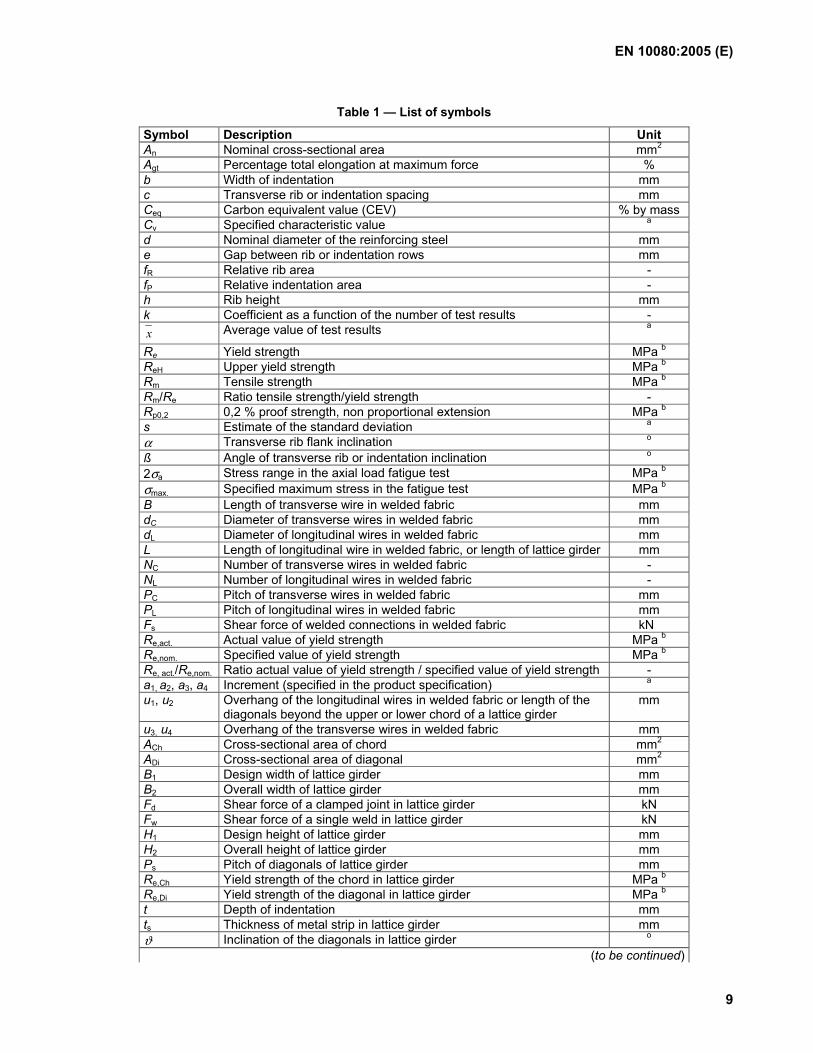
Table 1 — List of symbols
Symbol Description Unit An Nominal cross-sectional area mm2 Agt Percentage total elongation at maximum force % b Width of indentation mm c Transverse rib or indentation spacing mm Ceq Carbon equivalent value (CEV) % by mass Cv Specified characteristic value a
d Nominal diameter of the reinforcing steel mm e Gap between rib or indentation rows mm fR Relative rib area - fP Relative indentation area - h Rib height mm k Coefficient as a function of the number of test results - x Average value of test results a
Re Yield strength MPa b ReH Upper yield strength MPa b Rm Tensile strength MPa b Rm/Re Ratio tensile strength/yield strength - Rp0,2 0,2 % proof strength, non proportional extension MPa b s Estimate of the standard deviation a
α Transverse rib flank inclination o ß Angle of transverse rib or indentation inclination o 2σa Stress range in the axial load fatigue test MPa b σmax. Specified maximum stress in the fatigue test MPa b B Length of transverse wire in welded fabric mm dC Diameter of transverse wires in welded fabric mm dL Diameter of longitudinal wires in welded fabric mm L Length of longitudinal wire in welded fabric, or length of lattice girder mm NC Number of transverse wires in welded fabric - NL Number of longitudinal wires in welded fabric - PC Pitch of transverse wires in welded fabric mm PL Pitch of longitudinal wires in welded fabric mm Fs Shear force of welded connections in welded fabric kN Re,act. Actual value of yield strength MPa b Re,nom. Specified value of yield strength MPa b Re, act./Re,nom. Ratio actual value of yield strength / specified value of yield strength - a1, a2, a3, a4 Increment (specified in the product specification) a u1, u2 Overhang of the longitudinal wires in welded fabric or length of the
diagonals beyond the upper or lower chord of a lattice girder mm
u3, u4 Overhang of the transverse wires in welded fabric mm ACh Cross-sectional area of chord mm2 ADi Cross-sectional area of diagonal mm2 B1 Design width of lattice girder mm B2 Overall width of lattice girder mm Fd Shear force of a clamped joint in lattice girder kN Fw Shear force of a single weld in lattice girder kN H1 Design height of lattice girder mm H2 Overall height of lattice girder mm Ps Pitch of diagonals of lattice girder mm Re,Ch Yield strength of the chord in lattice girder MPa b Re,Di Yield strength of the diagonal in lattice girder MPa b t Depth of indentation mm ts Thickness of metal strip in lattice girder mm ϑ Inclination of the diagonals in lattice girder o
(to be continued)
EN 10080:2005 (E)
10
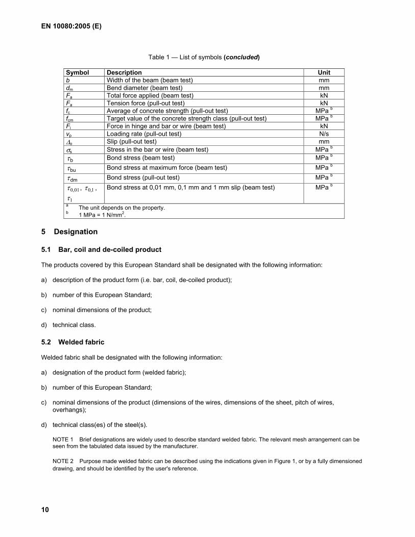
Table 1 — List of symbols (concluded)
Symbol Description Unit b Width of the beam (beam test) mm dm Bend diameter (beam test) mm Fa Total force applied (beam test) kN Fa Tension force (pull-out test) kN fc Average of concrete strength (pull-out test) MPa b
fcm Target value of the concrete strength class (pull-out test) MPa b
Fi Force in hinge and bar or wire (beam test) kN vp Loading rate (pull-out test) N/s ∆o Slip (pull-out test) mm σs Stress in the bar or wire (beam test) MPa b
bτ Bond stress (beam test) MPa b
buτ Bond stress at maximum force (beam test) MPa b
dmτ Bond stress (pull-out test) MPa b
01,0τ , 1,0τ ,
1τ Bond stress at 0,01 mm, 0,1 mm and 1 mm slip (beam test) MPa b
a The unit depends on the property. b 1 MPa = 1 N/mm2.
5 Designation
5.1 Bar, coil and de-coiled product
The products covered by this European Standard shall be designated with the following information:
a) description of the product form (i.e. bar, coil, de-coiled product);
b) number of this European Standard;
c) nominal dimensions of the product;
d) technical class.
5.2 Welded fabric
Welded fabric shall be designated with the following information:
a) designation of the product form (welded fabric);
b) number of this European Standard;
c) nominal dimensions of the product (dimensions of the wires, dimensions of the sheet, pitch of wires, overhangs);
d) technical class(es) of the steel(s).
NOTE 1 Brief designations are widely used to describe standard welded fabric. The relevant mesh arrangement can be seen from the tabulated data issued by the manufacturer.
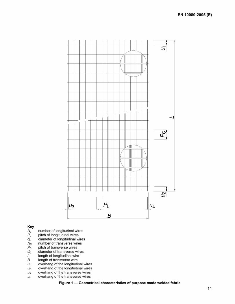
NOTE 2 Purpose made welded fabric can be described using the indications given in Figure 1, or by a fully dimensioned drawing, and should be identified by the user's reference.
EN 10080:2005 (E)
11
Key NL number of longitudinal wires PL pitch of longitudinal wires dL diameter of longitudinal wires NC number of transverse wires PC pitch of transverse wires dC diameter of transverse wires L length of longitudinal wire B length of transverse wire u1 overhang of the longitudinal wires u2 overhang of the longitudinal wires u3 overhang of the transverse wires u4 overhang of the transverse wires
Figure 1 — Geometrical characteristics of purpose made welded fabric
EN 10080:2005 (E)
12
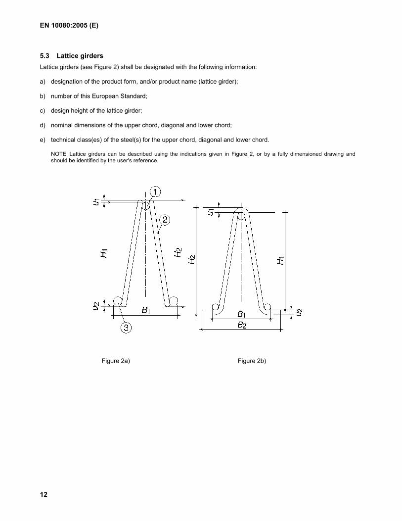
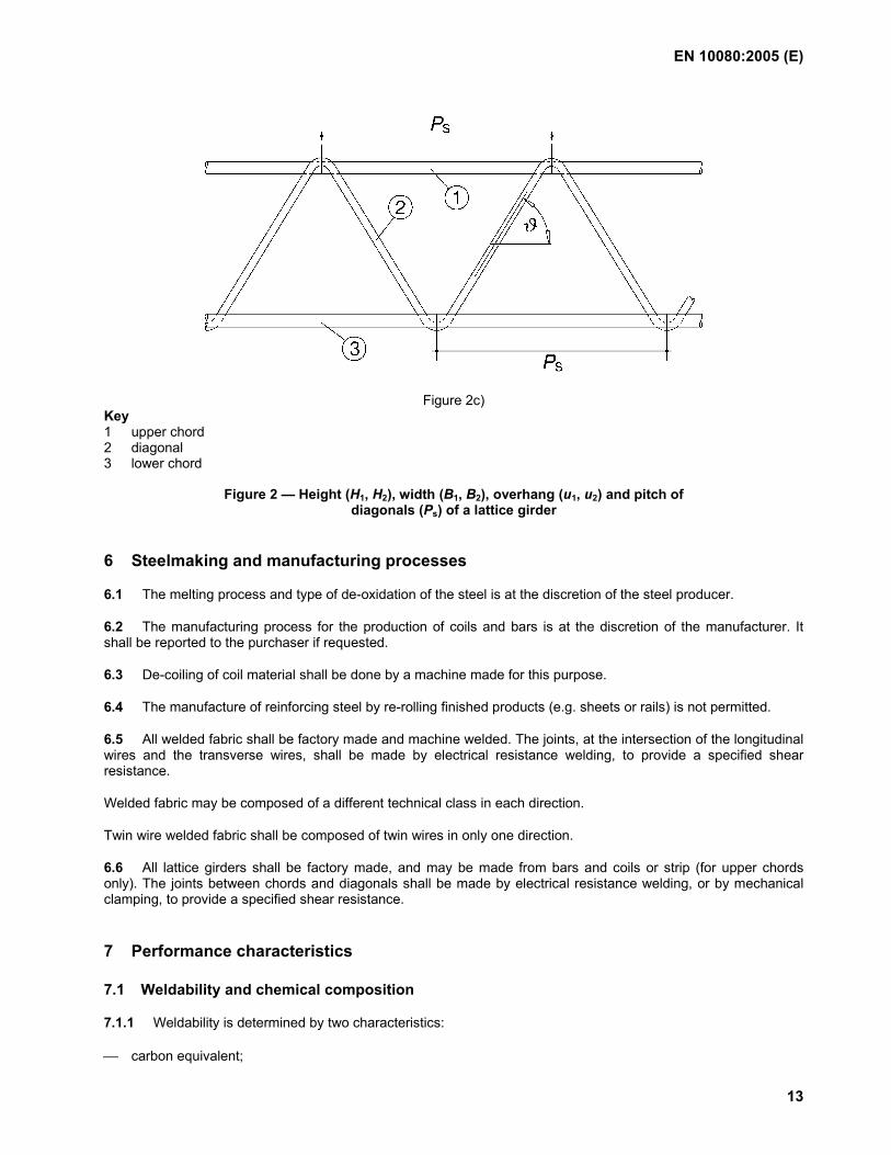
5.3 Lattice girders Lattice girders (see Figure 2) shall be designated with the following information:
a) designation of the product form, and/or product name (lattice girder);
b) number of this European Standard;
c) design height of the lattice girder;
d) nominal dimensions of the upper chord, diagonal and lower chord;
e) technical class(es) of the steel(s) for the upper chord, diagonal and lower chord.
NOTE Lattice girders can be described using the indications given in Figure 2, or by a fully dimensioned drawing and should be identified by the user's reference.
Figure 2a) Figure 2b)
EN 10080:2005 (E)
13
Figure 2c) Key 1 upper chord 2 diagonal 3 lower chord
Figure 2 — Height (H1, H2), width (B1, B2), overhang (u1, u2) and pitch of diagonals (Ps) of a lattice girder
6 Steelmaking and manufacturing processes
6.1 The melting process and type of de-oxidation of the steel is at the discretion of the steel producer.
6.2 The manufacturing process for the production of coils and bars is at the discretion of the manufacturer. It shall be reported to the purchaser if requested.
6.3 De-coiling of coil material shall be done by a machine made for this purpose.
6.4 The manufacture of reinforcing steel by re-rolling finished products (e.g. sheets or rails) is not permitted.
6.5 All welded fabric shall be factory made and machine welded. The joints, at the intersection of the longitudinal wires and the transverse wires, shall be made by electrical resistance welding, to provide a specified shear resistance.
Welded fabric may be composed of a different technical class in each direction.
Twin wire welded fabric shall be composed of twin wires in only one direction.
6.6 All lattice girders shall be factory made, and may be made from bars and coils or strip (for upper chords only). The joints between chords and diagonals shall be made by electrical resistance welding, or by mechanical clamping, to provide a specified shear resistance.
7 Performance characteristics
7.1 Weldability and chemical composition
7.1.1 Weldability is determined by two characteristics:
carbon equivalent;
EN 10080:2005 (E)
14
limitations on the content of certain elements.
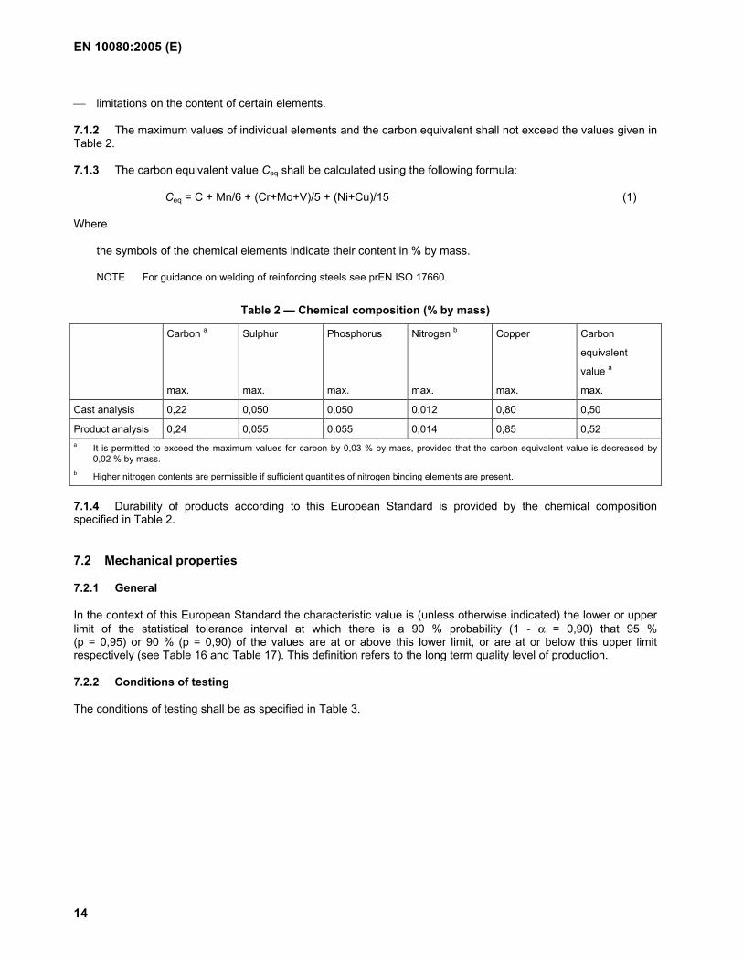
7.1.2 The maximum values of individual elements and the carbon equivalent shall not exceed the values given in Table 2.
7.1.3 The carbon equivalent value Ceq shall be calculated using the following formula:
Ceq = C + Mn/6 + (Cr+Mo+V)/5 + (Ni+Cu)/15 (1)
Where
the symbols of the chemical elements indicate their content in % by mass.
NOTE For guidance on welding of reinforcing steels see prEN ISO 17660.
Table 2 — Chemical composition (% by mass)
Carbon a
max.
Sulphur
max.
Phosphorus
max.
Nitrogen b
max.
Copper
max.
Carbon
equivalent
value a
max.
Cast analysis 0,22 0,050 0,050 0,012 0,80 0,50
Product analysis 0,24 0,055 0,055 0,014 0,85 0,52 a It is permitted to exceed the maximum values for carbon by 0,03 % by mass, provided that the carbon equivalent value is decreased by 0,02 % by mass. b Higher nitrogen contents are permissible if sufficient quantities of nitrogen binding elements are present.
7.1.4 Durability of products according to this European Standard is provided by the chemical composition specified in Table 2.
7.2 Mechanical properties
7.2.1 General
In the context of this European Standard the characteristic value is (unless otherwise indicated) the lower or upper limit of the statistical tolerance interval at which there is a 90 % probability (1 - α = 0,90) that 95 % (p = 0,95) or 90 % (p = 0,90) of the values are at or above this lower limit, or are at or below this upper limit respectively (see Table 16 and Table 17). This definition refers to the long term quality level of production.
7.2.2 Conditions of testing
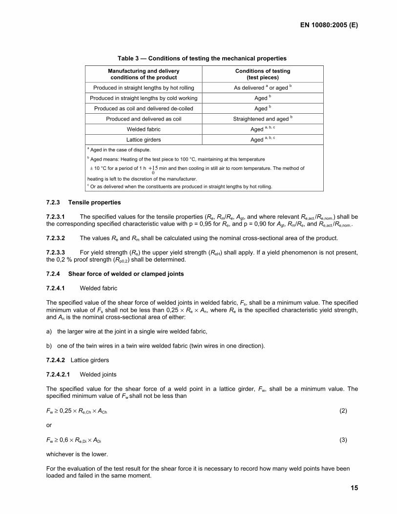
The conditions of testing shall be as specified in Table 3.
EN 10080:2005 (E)
15
Table 3 — Conditions of testing the mechanical properties
Manufacturing and delivery conditions of the product
Conditions of testing (test pieces)
Produced in straight lengths by hot rolling As delivered a or aged b
Produced in straight lengths by cold working Aged b
Produced as coil and delivered de-coiled Aged b
Produced and delivered as coil Straightened and aged b
Welded fabric Aged a, b, c
Lattice girders Aged a, b, c a Aged in the case of dispute. b Aged means: Heating of the test piece to 100 °C, maintaining at this temperature
± 10 °C for a period of 1 h 015+ min and then cooling in still air to room temperature. The method of
heating is left to the discretion of the manufacturer. c Or as delivered when the constituents are produced in straight lengths by hot rolling.
7.2.3 Tensile properties
7.2.3.1 The specified values for the tensile properties (Re, Rm/Re, Agt, and where relevant Re,act./Re,nom.) shall be the corresponding specified characteristic value with p = 0,95 for Re, and p = 0,90 for Agt, Rm/Re, and Re,act./Re,nom..
7.2.3.2 The values Re and Rm shall be calculated using the nominal cross-sectional area of the product.
7.2.3.3 For yield strength (Re) the upper yield strength (ReH) shall apply. If a yield phenomenon is not present, the 0,2 % proof strength (Rp0,2) shall be determined.
7.2.4 Shear force of welded or clamped joints
7.2.4.1 Welded fabric
The specified value of the shear force of welded joints in welded fabric, Fs, shall be a minimum value. The specified minimum value of Fs shall not be less than 0,25 × Re × An, where Re is the specified characteristic yield strength, and An is the nominal cross-sectional area of either:
a) the larger wire at the joint in a single wire welded fabric,
b) one of the twin wires in a twin wire welded fabric (twin wires in one direction).
7.2.4.2 Lattice girders
7.2.4.2.1 Welded joints
The specified value for the shear force of a weld point in a lattice girder, Fw, shall be a minimum value. The specified minimum value of Fw shall not be less than
Fw ≥ 0,25 × Re,Ch × ACh (2)
or
Fw ≥ 0,6 × Re,Di × ADi (3)
whichever is the lower.
For the evaluation of the test result for the shear force it is necessary to record how many weld points have been loaded and failed in the same moment.
EN 10080:2005 (E)
16
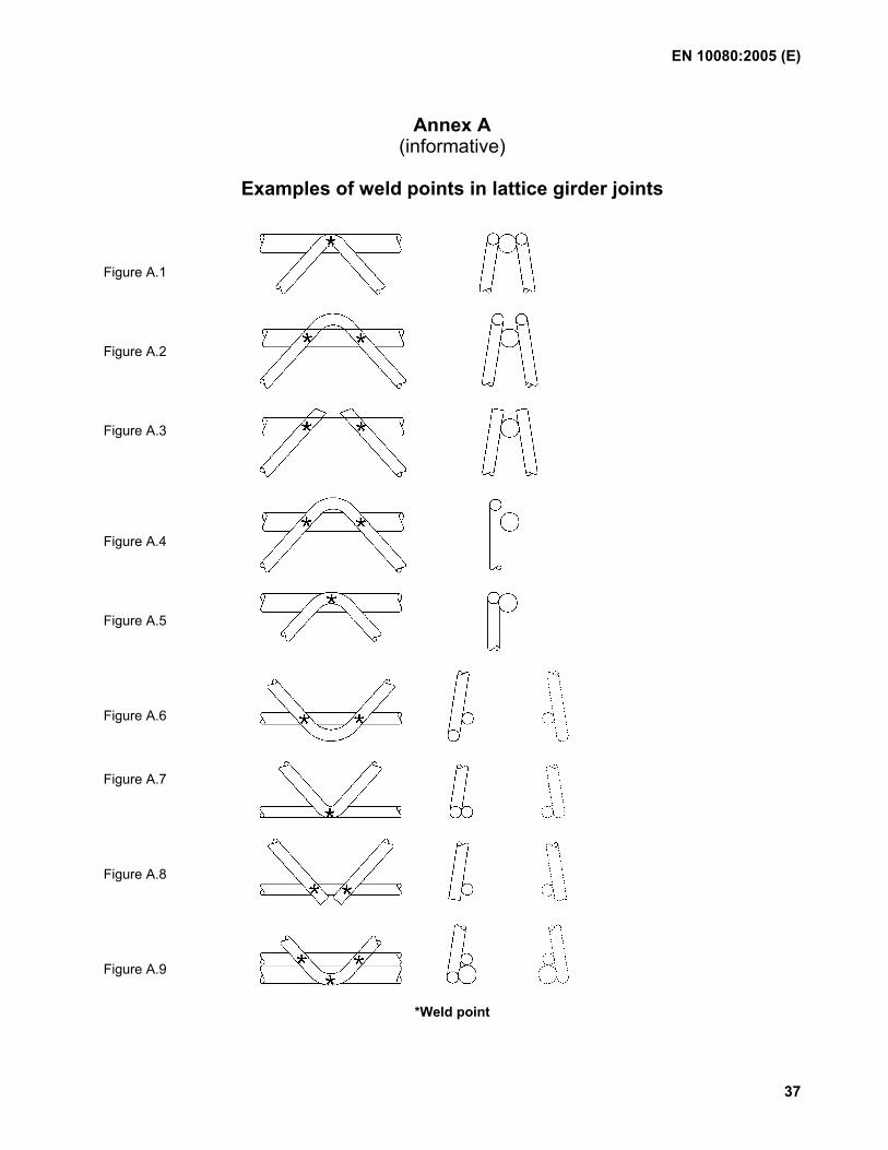
NOTE Annex A gives examples of weld points in a joint.
7.2.4.2.2 Clamped joints
Clamped joints are only used for joining the lower chord and the diagonals. The specified value for the shear force of a clamped joint in lattice girders, Fd, shall be a minimum value. The specified minimum value of Fd shall not be less than
Fd ≥ 0,25 × Re,Di × ADi (4)
7.2.5 Fatigue strength
If submitted to axial force controlled fatigue testing in the fluctuating tension range, the product shall withstand the specified number(s) of stress cycles. The stress shall vary sinusoidally, over the specified range of stress 2σa, from the specified σmax.
NOTE 2 σa and σmax should be expressed on the basis of the nominal cross-sectional area of the bar, rod or wire.
7.2.6 Suitability for bending
7.2.6.1 Suitability for bending shall be determined by the bend and/or rebend test.
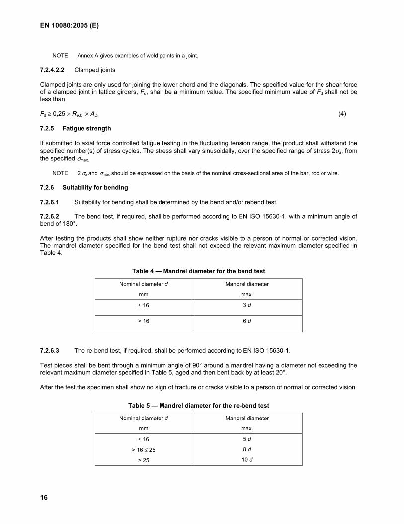
7.2.6.2 The bend test, if required, shall be performed according to EN ISO 15630-1, with a minimum angle of bend of 180°.
After testing the products shall show neither rupture nor cracks visible to a person of normal or corrected vision. The mandrel diameter specified for the bend test shall not exceed the relevant maximum diameter specified in Table 4.
Table 4 — Mandrel diameter for the bend test
Nominal diameter d
mm
Mandrel diameter
max.
≤ 16 3 d
> 16 6 d
7.2.6.3 The re-bend test, if required, shall be performed according to EN ISO 15630-1.
Test pieces shall be bent through a minimum angle of 90° around a mandrel having a diameter not exceeding the relevant maximum diameter specified in Table 5, aged and then bent back by at least 20°.
After the test the specimen shall show no sign of fracture or cracks visible to a person of normal or corrected vision.
Table 5 — Mandrel diameter for the re-bend test
Nominal diameter d
mm
Mandrel diameter
max.
≤ 16
> 16 ≤ 25
> 25
5 d
8 d
10 d
EN 10080:2005 (E)
17
7.3 Dimensions, mass and tolerances
7.3.1 Diameters, cross-sectional area
The nominal diameters up to and including 10,0 mm shall be in half millimetres, and above 10,0 mm, shall be in whole millimetres.
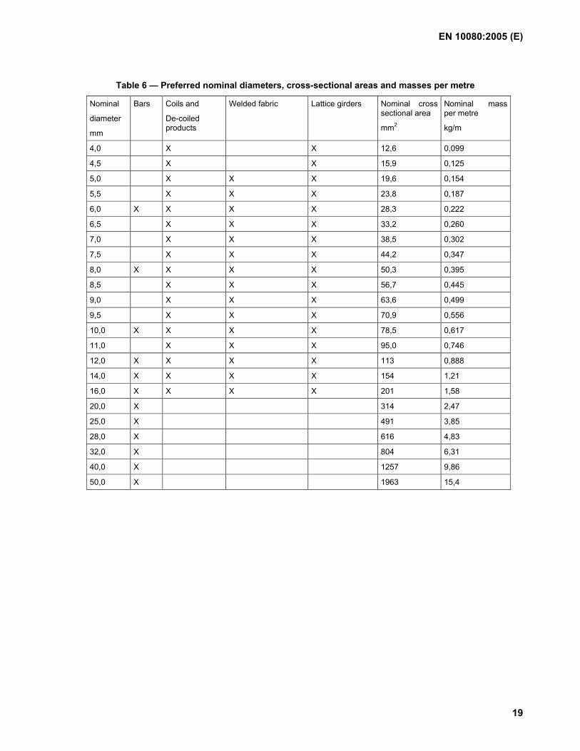
Preferred nominal diameters, cross-sectional areas and masses per metre are given in Table 6.
7.3.2 Mass per metre and tolerances
The values for the nominal mass per metre (see Table 6) are calculated from the values of the nominal cross-sectional area using a density value of 7,85 kg/dm3.
The permissible deviation from the nominal mass per metre shall not be more than ± 4,5 % on nominal diameters above 8,0 mm, and ± 6,0 % on nominal diameters 8,0 mm and below.
7.3.3 Length of bars
7.3.3.1 The nominal length of bars shall be agreed at the time of enquiry and order.
7.3.3.2 The permissible deviation from the nominal length shall be agreed at the time of enquiry and order.
7.3.4 Coil mass
The nominal coil mass shall be agreed at the time of enquiry and order.
7.3.5 Dimensions of welded fabric
7.3.5.1 Wire arrangement
7.3.5.1.1 General
The wires of a sheet shall be single wires and / or twin wires.
7.3.5.1.2 Relative diameters of wires
7.3.5.1.2.1 For single wire fabric, the nominal diameters of wires shall meet the following requirement
dmin. ≥ 0,6 dmax. (5)
where
dmax. is the nominal diameter of the thickest wire,
dmin. is the nominal diameter of the crossing wire.
Other requirements may be agreed at the time of enquiry and order.
7.3.5.1.2.2 For welded fabric with twin wires in one direction, the nominal diameters of the wires shall meet the following requirement
0,7 ds ≤ dT ≤ 1,25 ds (6)
where
ds is the nominal diameter of the single wires,
dT is the nominal diameter of the twin wires.
EN 10080:2005 (E)
18
Other requirements may be agreed at the time of enquiry and order.
7.3.5.1.3 Preferred pitch and overhang
The pitch of longitudinal wires and transverse wires shall not be less than 50 mm.
NOTE The overhang should not be less than 25 mm.
7.3.5.2 Dimensions and tolerances on dimensions
The nominal length, width, pitch and overhangs of welded fabric shall be agreed at the time of enquiry and order.
The permitted deviations for welded fabric are:
Length and width of the welded fabric: ± 25 mm or ± 0,5 % whichever is greater; wire pitch: ± 15 mm or ± 7,5 % whichever is greater; overhangs: to be agreed at the time of enquiry and order.
Special tolerance requirements may be agreed between the manufacturer and the purchaser.
7.3.6 Dimensions of lattice girders
7.3.6.1 Configurations
Where wires are welded together, they shall meet the requirement that dmin. / dmax. is greater than 0,3.
If metal strips are welded to wires, the following limitation shall apply:
ts ≥ 0,15 d (7)
where
d is the nominal diameter of the diagonal,
ts is the thickness of the metal strip.
7.3.6.2 Dimensions and tolerances on dimensions
The nominal length, height, width and pitch of lattice girders shall be agreed at the time of enquiry and order.
Maximum manufacturing tolerances shall be as follows:
length (L) : ± 40 mm if L ≤ 5,0 m; : ± 0,8 %, if L > 5,0 m; height (H1, H2) : 1
3+− mm;
width (B1, B2) : ± 7,5 mm; pitch (Ps) : ± 2,5 mm;
maximum overhang: may be agreed at the time of enquiry and order.
EN 10080:2005 (E)
19
Table 6 — Preferred nominal diameters, cross-sectional areas and masses per metre
Nominal
diameter
mm
Bars Coils and
De-coiled products
Welded fabric Lattice girders Nominal cross sectional area
mm2
Nominal mass per metre
kg/m
4,0 X X 12,6 0,099
4,5 X X 15,9 0,125
5,0 X X X 19,6 0,154
5,5 X X X 23,8 0,187
6,0 X X X X 28,3 0,222
6,5 X X X 33,2 0,260
7,0 X X X 38,5 0,302
7,5 X X X 44,2 0,347
8,0 X X X X 50,3 0,395
8,5 X X X 56,7 0,445
9,0 X X X 63,6 0,499
9,5 X X X 70,9 0,556
10,0 X X X X 78,5 0,617
11,0 X X X 95,0 0,746
12,0 X X X X 113 0,888
14,0 X X X X 154 1,21
16,0 X X X X 201 1,58
20,0 X 314 2,47
25,0 X 491 3,85
28,0 X 616 4,83
32,0 X 804 6,31
40,0 X 1257 9,86
50,0 X 1963 15,4
EN 10080:2005 (E)
20
7.4 Bond strength and surface geometry
7.4.1 General
Ribbed and indented steel products covered by this European Standard are characterized by their surface geometry, by means of which bond with the concrete is achieved.
Bond property requirements of ribbed and indented reinforcing steels shall be based on surface geometry.
Alternatively, bond property requirements of ribbed and indented reinforcing steels may be determined by appropriate bond tests, see Annexes C and D. The assessment criteria of these tests shall be as given in e.g. the appropriate product specification or design standard. In this case, provisions shall also be given for establishing factory production control requirements for the surface geometry based on the bond test results.
7.4.2 Surface geometry of ribbed steel
7.4.2.1 General
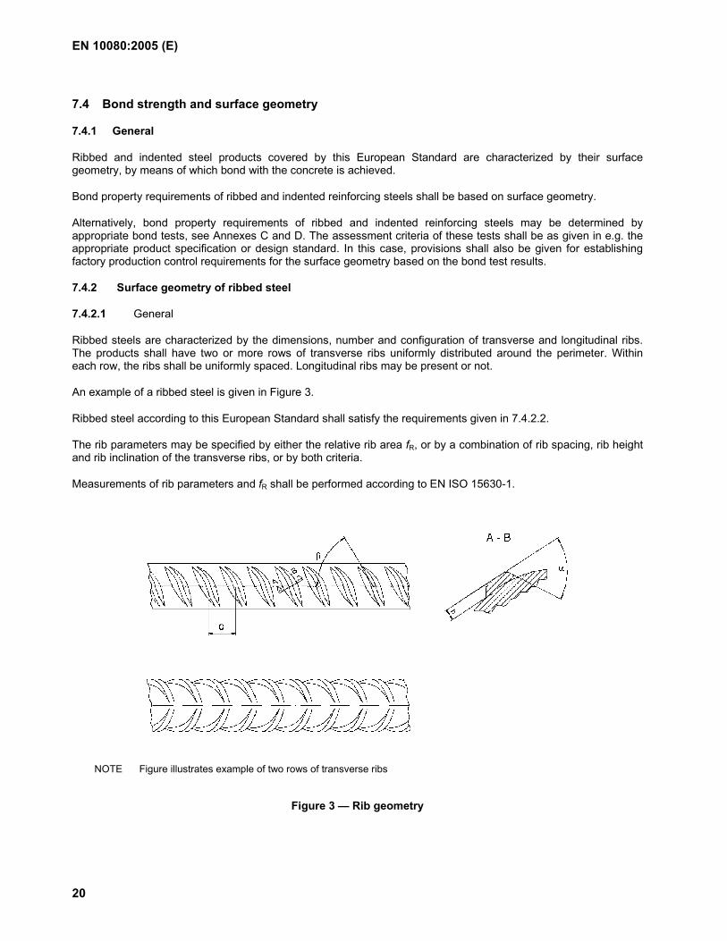
Ribbed steels are characterized by the dimensions, number and configuration of transverse and longitudinal ribs. The products shall have two or more rows of transverse ribs uniformly distributed around the perimeter. Within each row, the ribs shall be uniformly spaced. Longitudinal ribs may be present or not.
An example of a ribbed steel is given in Figure 3.
Ribbed steel according to this European Standard shall satisfy the requirements given in 7.4.2.2.
The rib parameters may be specified by either the relative rib area fR, or by a combination of rib spacing, rib height and rib inclination of the transverse ribs, or by both criteria.
Measurements of rib parameters and fR shall be performed according to EN ISO 15630-1.
NOTE Figure illustrates example of two rows of transverse ribs
Figure 3 — Rib geometry
EN 10080:2005 (E)
21
7.4.2.2 Transverse ribs
7.4.2.2.1 The values for rib spacing, rib height and rib inclination shall be within the ranges given in Table 7, where d is the nominal diameter of the bar, rod or wire.
Table 7 — Ranges for the rib parameters
Rib height h Rib spacing c Rib inclination β
0,03 d to 0,15 d 0,4 d to 1,2 d 35° to 75°
7.4.2.2.2 Transverse ribs shall have a crescent shape and shall merge smoothly into the core of the product.
7.4.2.2.3 The projection of the transverse ribs shall extend over at least 75 % of the circumference of the product, which shall be calculated from the nominal diameter.
7.4.2.2.4 The transverse rib flank inclination (α) shall be ≥ 45° and the transition from the rib to the core of the product shall be radiused.
7.4.2.3 Longitudinal ribs
Where longitudinal ribs are present, their height shall not exceed 0,15 d, where d is the nominal diameter of the product.
7.4.3 Surface geometry of indented steel
7.4.3.1 General
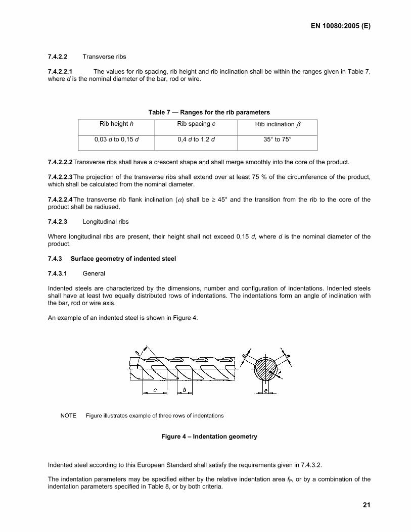
Indented steels are characterized by the dimensions, number and configuration of indentations. Indented steels shall have at least two equally distributed rows of indentations. The indentations form an angle of inclination with the bar, rod or wire axis.
An example of an indented steel is shown in Figure 4.
NOTE Figure illustrates example of three rows of indentations
Figure 4 – Indentation geometry
Indented steel according to this European Standard shall satisfy the requirements given in 7.4.3.2.
The indentation parameters may be specified either by the relative indentation area fP, or by a combination of the indentation parameters specified in Table 8, or by both criteria.
EN 10080:2005 (E)
22
Measurements of indentation parameters and fP shall be performed according to EN ISO 15630-1.
7.4.3.2 Indentation geometry
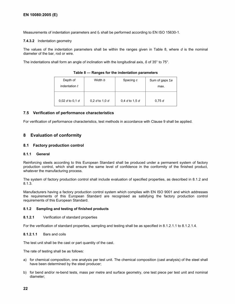
The values of the indentation parameters shall be within the ranges given in Table 8, where d is the nominal diameter of the bar, rod or wire.
The indentations shall form an angle of inclination with the longitudinal axis, ß of 35° to 75°.
Table 8 — Ranges for the indentation parameters
Depth of
indentation t
Width b
Spacing c
Sum of gaps Σe
max.
0,02 d to 0,1 d
0,2 d to 1,0 d
0,4 d to 1,5 d
0,75 d
7.5 Verification of performance characteristics
For verification of performance characteristics, test methods in accordance with Clause 9 shall be applied.
8 Evaluation of conformity
8.1 Factory production control
8.1.1 General
Reinforcing steels according to this European Standard shall be produced under a permanent system of factory production control, which shall ensure the same level of confidence in the conformity of the finished product, whatever the manufacturing process.
The system of factory production control shall include evaluation of specified properties, as described in 8.1.2 and 8.1.3.
Manufacturers having a factory production control system which complies with EN ISO 9001 and which addresses the requirements of this European Standard are recognised as satisfying the factory production control requirements of this European Standard.
8.1.2 Sampling and testing of finished products
8.1.2.1 Verification of standard properties
For the verification of standard properties, sampling and testing shall be as specified in 8.1.2.1.1 to 8.1.2.1.4.
8.1.2.1.1 Bars and coils
The test unit shall be the cast or part quantity of the cast.
The rate of testing shall be as follows:
a) for chemical composition, one analysis per test unit. The chemical composition (cast analysis) of the steel shall have been determined by the steel producer;
b) for bend and/or re-bend tests, mass per metre and surface geometry, one test piece per test unit and nominal diameter;
EN 10080:2005 (E)
23
c) for tensile tests, one test piece per 30 t with at least three test pieces per test unit and nominal diameter.
Test results shall be evaluated in accordance with 8.1.3.
8.1.2.1.2 De-coiled products
The processor of products in coil shall operate a documented procedure (appropriate FPC), which ensures that the de-coiled products continue to meet the specified property requirements of the appropriate product specification. This procedure includes, as a minimum, the following:
a) visual inspection for surface geometry damage of every coil processed;
b) surface geometry measurement on at least one sample per day and produced size;
c) tensile testing at a frequency of at least one sample per machine type (roller or spinner) per week from each of two processed sizes. The sampling shall be such that all machines and sizes are covered in a six month period. Only one sample shall be taken from each coil.
NOTE Testing may be carried out either by the processor using his own resources (internal or external) or by the processor in co-operation with the coil manufacturer. The tests are not to be seen as release tests, but as the basis for the assessment of the long term quality level (LTQL) as described in 8.5.
8.1.2.1.3 Welded fabric
The test unit is composed of sheets of the same combination of reinforcing technical classes and diameters produced on the same welding machine of a maximum mass of 50 t.
For the verification of properties, samples shall be taken in accordance with Table 9. These samples may be taken according to the producer's choice, either on one sheet or on different sheets, provided that different wires are tested.
All specified welded fabric dimensions (length, width, pitch, overhang) (see 7.3.5) shall be measured.
The chemical composition (cast analysis) of the material shall have been determined by the steel producer. Compliance shall be confirmed to the welded fabric manufacturer, which shall include a statement of the chemical composition, if required by the purchaser.
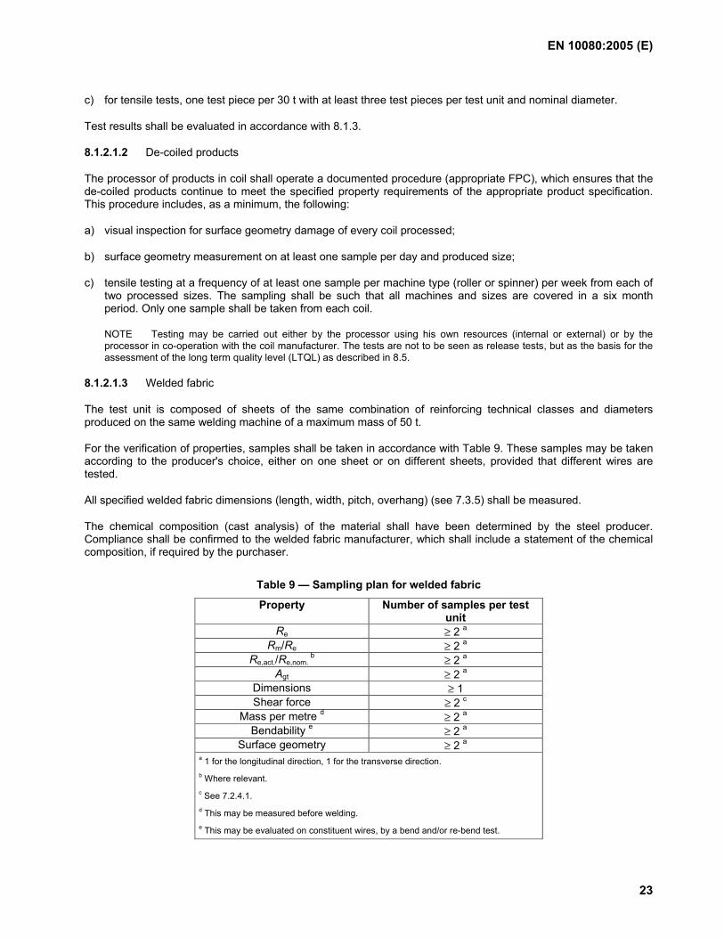
Table 9 — Sampling plan for welded fabric
Property Number of samples per test unit
Re ≥ 2 a Rm/Re ≥ 2 a
Re,act./Re,nom. b ≥ 2 a
Agt ≥ 2 a Dimensions ≥ 1 Shear force ≥ 2 c
Mass per metre d ≥ 2 a Bendability e ≥ 2 a
Surface geometry ≥ 2 a a 1 for the longitudinal direction, 1 for the transverse direction. b Where relevant. c See 7.2.4.1. d This may be measured before welding. e This may be evaluated on constituent wires, by a bend and/or re-bend test.
EN 10080:2005 (E)
24
8.1.2.1.4 Lattice girders
The test unit is composed of lattice girders of the same combination of reinforcing technical classes and diameters produced on the same welding machine of a maximum mass of 50 t.
Samples shall be taken in the event of any change in the constituent material dimensions or technical classes of steel used, and at least once per day of production per machine.
For each combination of nominal diameters, modifications to the lattice girder height and length do not affect the number of samples to be taken. The number of samples of chords and diagonals per test unit is given in Table 10.
All specified lattice girder dimensions (length, height, width, pitch) (see 7.3.6) shall be measured.
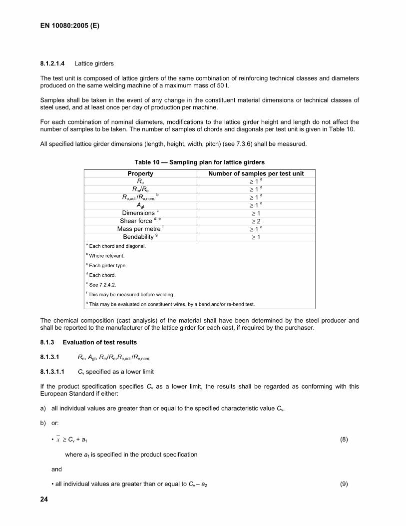
Table 10 — Sampling plan for lattice girders
Property Number of samples per test unit Re ≥ 1 a
Rm/Re ≥ 1 a Re,act./Re,nom.
b ≥ 1 a Agt ≥ 1 a
Dimensions c ≥ 1 Shear force d, e ≥ 2
Mass per metre f ≥ 1 a
Bendability g ≥ 1 a Each chord and diagonal. b Where relevant. c Each girder type. d Each chord. e See 7.2.4.2. f This may be measured before welding. g This may be evaluated on constituent wires, by a bend and/or re-bend test.
The chemical composition (cast analysis) of the material shall have been determined by the steel producer and shall be reported to the manufacturer of the lattice girder for each cast, if required by the purchaser.
8.1.3 Evaluation of test results
8.1.3.1 Re, Agt, Rm/Re,Re,act./Re,nom.
8.1.3.1.1 Cv specified as a lower limit
If the product specification specifies Cv as a lower limit, the results shall be regarded as conforming with this European Standard if either:
a) all individual values are greater than or equal to the specified characteristic value Cv,
b) or:
• x ≥ Cv + a1 (8)
where a1 is specified in the product specification
and
• all individual values are greater than or equal to Cv – a2 (9)
EN 10080:2005 (E)
25
where a2 is specified in the product specification.
8.1.3.1.2 Cv specified as an upper limit
If the product specification specifies Cv as an upper limit, the results shall be regarded as conforming with this European Standard if either:
a) all individual values are equal to or lower than the specified characteristic value Cv,
b) or:
• x ≤ Cv – a3 (10)
where
a3 is specified in the product specification
and
• all individual values are equal to or lower than
Cv + a4 (11)
where
a4 is specified in the product specification.
8.1.3.2 Bendability, shear force, geometry, mass per metre
In the bend and/or re-bend test, all test pieces shall fulfil the requirements of the product specification.
If testing the shear force of welded or clamped joints, all individual values shall fulfil the requirements of the product specification.
If testing the surface geometry, the results shall meet the requirements of the product specification.
If testing the mass per metre, no individual value shall be outside the tolerances specified in 7.3.2.
8.1.3.3 Test units which do not comply with specified requirements may be retested according to a procedure documented in the factory production control (FPC) system.
8.1.4 Traceability
Delivered batches shall be identifiable and traceable to the manufacturer and, if required, to their production data. The manufacturer shall establish and maintain the records required and shall identify the products and their delivery documentation accordingly.
NOTE The records should be maintained by the processor according to national provisions.
8.2 Initial type testing
The samples shall be taken as random samples from the production material presented for testing. Care shall be taken to ensure that the samples genuinely reflect the properties of the material to be tested. Tests shall be carried out on the full cross-section of the product. Any sample preparation shall be in accordance with EN ISO 377.
EN 10080:2005 (E)
26
8.2.1 Standard properties
8.2.1.1 Bars and coils
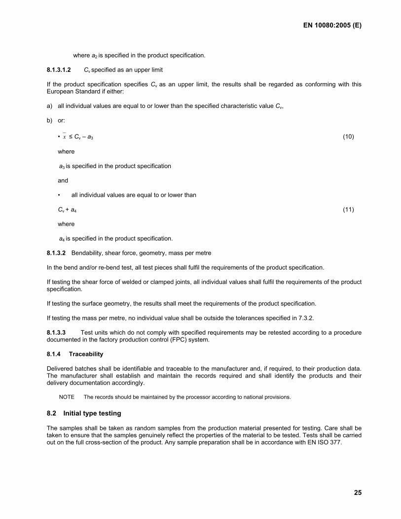
For each manufacturing process the type and number of tests for initial type testing shall be as defined in Table 11, and the testing schedule shall be as defined in Table 12.
Table 11 — Type and number of tests for initial type testing and continuous surveillance of bars and coils
Frequency Operation Diameter
Standard properties a
Fatigue b
Initial type testing Upper, middle and bottom of diameter range
3 casts per diameter of bar/coil (rod, wire)
5 samples on each sampled diameter
Continuous surveillance
One diameter (as appropriate)
3 casts per diameter of bar/coil (rod, wire)
5 samples once a year
a For standard properties tests shall be performed on the characteristics described in Table 12. b Where required.
Table 12 — Testing schedule for performance characteristics of bars, coils and de-coiled products
Property Bars/Coils (rod, wire) (number of tests per cast)
De-coiled products (rod, wire)
(number of tests per coil)
Re Rm/Re
Re,act./Re,nom. a
Agt Mass per metre
Bendability b
Surface geometry c
Chemistry (incl. CEV)
10 10 10 10 3 3 3 1
3 3 3 3 1 1 3 0
a When relevant. b Bend test and/or re-bend test. c Alternatively, testing according to Annex C or Annex D.
8.2.1.2 De-coiled products
Products shall be sampled and tested according to Table 12 from each machine type (roller or spinner) of the de-coiler and from each coil manufacturing process. Samples shall be selected for test from one coil from each of the largest and smallest diameters produced.
8.2.1.3 Welded fabric
Products shall be sampled and tested from each machine.
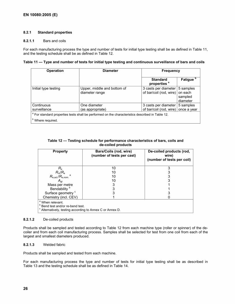
For each manufacturing process the type and number of tests for initial type testing shall be as described in Table 13 and the testing schedule shall be as defined in Table 14.
EN 10080:2005 (E)
27
Table 13 — Type and number of tests for initial type testing and continuous surveillance of welded fabric
Frequency Operation Diameter
Standard propertiesa
Fatigueb
Initial type testing Upper, middle and bottom of size range (diameter combinations)
3 test units per size 5 samples on each sampled size
Continuous surveillance
One size (diameter combination) (as appropriate)
3 test units per size 5 samples once a year
a For standard properties tests shall be performed on the characteristics described in Table 14. b Where required.
Table 14 — Testing for standard properties of welded fabric
Property Number of tests per test unit Cross-section
(mass per metre) 4 = 2 (longitudinal) + 2 (transverse)
Re 4 = 2 (longitudinal) + 2 (transverse) Rm/Re 4 = 2 (longitudinal) + 2 (transverse)
Re,act./Re,nom. a 4 = 2 (longitudinal) + 2 (transverse)
Agt 4 = 2 (longitudinal) + 2 (transverse) Weld shear force 3 Surface geometry 4 = 2 (longitudinal) + 2 (transverse)
Dimensions of the welded fabric 1 a Where relevant.
8.2.1.4 Lattice girders
Products shall be sampled and tested from different combinations of reinforcing steel diameters which represent the producer's size range.
Tests shall be performed on the samples selected from 3 test units (see 8.1.2.1.4).
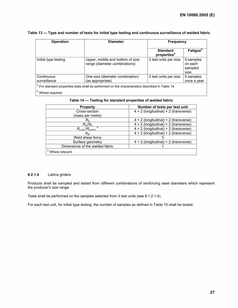
For each test unit, for initial type testing, the number of samples as defined in Table 15 shall be tested.
EN 10080:2005 (E)
28
Table 15 — Number of samples for initial type testing and continuous surveillance of lattice girders
Number of tests per test unit for Property upper chord diagonals lower chord
Cross-section (mass per metre)
2 2/2 2/2
Re 2 2/2 2/2 Rm/Re 2 2/2 2/2
Re,act./Re,nom. a 2 2/2 2/2
Agt 2 2/2 2/2 Surface geometry b 2 2/2 2/2
Shear force 3 -/- 3/3c Dimensions 1 per unit
a Where relevant. b For ribbed and indented reinforcing steel. c For clamped joints see 7.2.4.2.2.
8.2.2 Fatigue testing
8.2.2.1 Bars and coils
Where a product specification requires fatigue performance, 5 samples shall be taken from different bars or coils in accordance with Table 11.
8.2.2.2 De-coiled products
Where a product specification requires fatigue performance, 5 samples shall be taken from each production site from one de-coiling machine type from the largest diameter being produced.
8.2.2.3 Welded fabric
Where a product specification requires fatigue performance, 5 samples, including a weld, shall be taken from various wires of one nominal diameter in accordance with Table 13.
8.2.2.4 Lattice girders
Fatigue testing is not required for lattice girders.
8.3 Continuous surveillance of factory production control and audit testing
8.3.1 General
The purpose of continuous surveillance is to:
a) confirm that the system of factory production control continues to comply with the requirements of 8.1;
b) select samples for audit testing according to 8.3.2.
Continuous surveillance shall be carried out as follows:
c) Auditing the manufacturer's factory production control system to verify that it continues to function satisfactorily.
d) Sampling and testing of the products as described in 8.3.2.
EN 10080:2005 (E)
29
8.3.2 Audit testing of samples taken at the factory
8.3.2.1 Bars and coils
8.3.2.1.1 Standard properties
Standard properties shall be verified by sampling and testing the products, as defined in Tables 11 and 12.
Tests shall be carried out on samples taken at random from each manufacturing process route. Samples shall be selected so that the greatest number of sizes are tested over a period of 5 years.
8.3.2.1.2 Fatigue
Where the product specification requires fatigue performance, once a year, 5 samples shall be taken from different bars or coils of one diameter. The sampling shall be carried out in such a way as to cover the maximum number and spread of diameters across the manufacturer's diameter range over a period of 5 years.
8.3.2.2 De-coiled products
8.3.2.2.1 Standard properties
Samples shall be selected from one coil and diameter processed for each straightening process. The test schedule shall be in accordance with Table 12.
NOTE The samples should be such that all machines and sizes are covered in a 24 month period.
8.3.2.2.2 Fatigue
Where the product specification requires fatigue performance, once a year 5 samples shall be taken from each production site from one de-coiling machine from the largest diameter being processed. The sampling shall be carried out in such a way as to cover the combination of material manufacturing process and type of de-coiler over a period of 5 years.
8.3.2.3 Welded fabric
8.3.2.3.1 Standard properties
Standard properties shall be verified by sampling and testing the products as defined in Tables 13 and 14.
Tests shall be carried out on samples taken at random from each manufacturing process route. The sampling shall be carried out in such a way as to cover the maximum number and spread of sizes across the manufacturer's size range over a period of 5 years.
8.3.2.3.2 Fatigue
Where the product specification requires fatigue performance, once a year 5 samples shall be taken at random from wires produced from each manufacturing process. Sampling shall be carried out in such a way to ensure that the maximum number and spread of sizes are covered over a period of 5 years.
8.3.2.4 Lattice girders
8.3.2.4.1 Standard properties
Standard properties shall be verified by sampling and testing the products as defined in Table 15.
Tests shall be carried out on samples taken at random from each manufacturing process route. Samples shall be selected so that the greatest number of sizes is tested over a period of 5 years.
EN 10080:2005 (E)
30
8.3.2.4.2 Fatigue
Fatigue testing of lattice girders is not required.
8.4 Evaluation, reporting and action
8.4.1 Initial type testing
For each test programme a statistical evaluation of test results shall be carried out using appropriate techniques.
If the results for either standard properties or fatigue show that the production does not conform to the requirements, then approval to produce to this European Standard shall not be granted to the manufacturer. Appropriate measures shall be taken by the manufacturer in order to correct any deficiencies noted. The measures will depend on the type and significance of the deficiencies noted but may include changes to production and inspection conditions.
8.4.2 Continuous surveillance
For each test programme, excluding de-coiled material, a statistical evaluation of test results shall be carried out using appropriate techniques. The results, including the statistical analysis of test results, shall be recorded in a surveillance inspection report.
The results of the manufacturer's long term quality level assessment shall be evaluated every six months.
If the results for either standard properties, fatigue or long term quality level show that the production does not conform to the requirements, appropriate measures shall be taken. The measures will depend on the type and significance of the deficiencies noted and may include:
intensification of factory production control (increase in the frequency of testing);
change to the conditions of production;
increased frequency of surveillance inspection.
8.4.3 Standard properties
For both initial type testing and continuous surveillance, the products shall be deemed to comply if they meet the test requirements of the product specification.
8.4.4 Fatigue testing
Where required by the product specification, for both the initial type testing and continuous surveillance, the products shall be deemed to comply with this European Standard if they endure the number of cycles required by the product specification. In the case of any failure, the test shall be considered invalid if it is initiated from a defect unique to the test piece or in the area adjacent to the testing machine grips; in this case a further single test shall be carried out (see EN ISO 15630-1).
If the above mentioned criteria are not fulfilled, one further series of five test pieces shall be selected from the nominal size represented. If the criteria are fulfilled for this supplementary series, the material shall be deemed to comply with this European Standard. If not, an investigation shall be carried out and appropriate measures shall be taken.
EN 10080:2005 (E)
31
8.5 Assessment of the long term quality level
8.5.1 General
The results of tests on all test units of continuous production shall be collated and statistically evaluated for Re, Agt, Rm/Re and Re,act./Re,nom. (where relevant) taking either the number of results corresponding to the preceding six months operation or the last 200 results, whichever is the greater.
8.5.2 Evaluation of the test results
The evaluation shall be carried out per nominal diameter.
The following requirement shall be satisfied for Re, Agt and Rm/Re:
x - ks ≥ Cv (12)
The following requirement shall be satisfied regarding Re,act./Re,nom. and the upper limit of Rm/Re where relevant:
x + ks ≤ Cv (13)
where
x is the average value;
s is the estimate of the standard deviation of the population;
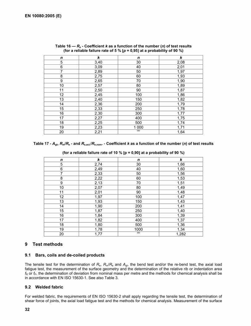
k is the coefficient listed in Table 16 for Re and in Table 17 for Agt, Rm/Re and Re,act./Re,nom.;
Cv is the specified characteristic value.
The foregoing is based on the assumption that the distribution of a large number of results is normal but this is not a requirement of this European Standard. However, the following alternative methods may be used to establish conformity of the production with the requirements of this European Standard:
a) graphical methods including control charts;
b) non-parametric statistical techniques.
EN 10080:2005 (E)
32
Table 16 — Re - Coefficient k as a function of the number (n) of test results (for a reliable failure rate of 5 % [[[[p = 0,95]]]] at a probability of 90 %)
n k n k 5 3,40 30 2,08 6 3,09 40 2,01 7 2,89 50 1,97 8 2,75 60 1,93 9 2,65 70 1,90 10 2,57 80 1,89 11 2,50 90 1,87 12 2,45 100 1,86 13 2,40 150 1,82 14 2,36 200 1,79 15 2,33 250 1,78 16 2,30 300 1,77 17 2,27 400 1,75 18 2,25 500 1,74 19 2,23 1 000 1,71 20 2,21 oo 1,64
Table 17 - Agt, Rm/Re - and Re,act./Re,nom. - Coefficient k as a function of the number (n) of test results
(for a reliable failure rate of 10 % [[[[p = 0,90]]]] at a probability of 90 %)
n k n k 5 2,74 30 1,66 6 2,49 40 1,60 7 2,33 50 1,56 8 2,22 60 1,53 9 2,13 70 1,51 10 2,07 80 1,49 11 2,01 90 1,48 12 1,97 100 1,47 13 1,93 150 1,43 14 1,90 200 1,41 15 1,87 250 1,40 16 1,84 300 1,39 17 1,82 400 1,37 18 1,80 500 1,36 19 1,78 1000 1,34 20 1,77 oo 1,282
9 Test methods
9.1 Bars, coils and de-coiled products
The tensile test for the determination of Re, Rm/Re and Agt, the bend test and/or the re-bend test, the axial load fatigue test, the measurement of the surface geometry and the determination of the relative rib or indentation area fR or fP, the determination of deviation from nominal mass per metre and the methods for chemical analysis shall be in accordance with EN ISO 15630-1. See also Table 3.
9.2 Welded fabric
For welded fabric, the requirements of EN ISO 15630-2 shall apply regarding the tensile test, the determination of shear force of joints, the axial load fatigue test and the methods for chemical analysis. Measurement of the surface
EN 10080:2005 (E)
33
geometry and the determination of the relative rib or indentation area fR or fP and the determination of deviation from nominal mass per metre shall be in accordance with EN ISO 15630-1. See also Table 3.
9.3 Lattice girders
The tensile test for the determination of Re, Rm/Re and Agt, the measurement of the surface geometry and of the relative rib or indentation area fR or fP, the determination of deviation from nominal mass per metre and the methods for chemical analysis shall be in accordance with EN ISO 15630-1. For the measurement of the shear force of welded or clamped joints in lattice girders, the methods in Annex B shall apply. See also Table 3.
10 Identification of the manufacturer and the technical class
NOTE For CE marking see Annex ZA.
10.1 Bar
10.1.1 Identification of the manufacturer
10.1.1.1 Ribbed or indented steels
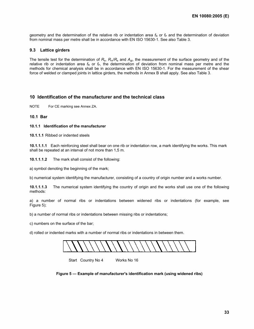
10.1.1.1.1 Each reinforcing steel shall bear on one rib or indentation row, a mark identifying the works. This mark shall be repeated at an interval of not more than 1,5 m.
10.1.1.1.2 The mark shall consist of the following:
a) symbol denoting the beginning of the mark;
b) numerical system identifying the manufacturer, consisting of a country of origin number and a works number.
10.1.1.1.3 The numerical system identifying the country of origin and the works shall use one of the following methods:
a) a number of normal ribs or indentations between widened ribs or indentations (for example, see Figure 5);
b) a number of normal ribs or indentations between missing ribs or indentations;
c) numbers on the surface of the bar;
d) rolled or indented marks with a number of normal ribs or indentations in between them.
Start Country No 4 Works No 16
Figure 5 — Example of manufacturer's identification mark (using widened ribs)
EN 10080:2005 (E)
34
10.1.1.1.4 The symbol indicating the start of the mark shall be one of the following:
a) Where the marking method uses widened ribs or indentations, the symbol identifying the start of the mark shall consist of two consecutive widened ribs or indentations. (For example see Figure 5).
b) Where the marking method uses missing ribs or indentations, the symbol identifying the start of the mark shall consist of two consecutive missing ribs or indentations.
c) Where numbers are rolled onto the surface of the bar the symbol indicating the start of the mark shall be an X or O.
d) Where marks are rolled or indented onto the surface, the start of the mark shall consist of two marks between one pair of normal ribs or indentations.
10.1.1.1.5 The country of origin shall be indicated by a number between 1 and 9, according to Table 18. (For example see Figure 5).
10.1.1.1.6 The works number shall consist of a one or two digit number between 1 and 99, except for multiples of 10. (For example, see Figure 5).
Table 18 — Identification of the country of origin
Country Country number Austria, Czech Republic, Germany, Poland, Slovakia 1 Belgium, Netherlands, Luxembourg, Switzerland 2 France, Hungary 3 Italy, Malta, Slovenia 4 UK, Ireland, Iceland 5 Denmark, Estonia, Finland, Latvia, Lithuania, Norway, Sweden
6
Portugal, Spain 7 Cyprus, Greece 8 Other countries 9
10.1.1.2 Plain steels
10.1.1.2.1 Plain steels shall be identified with the same information as ribbed or indented steels.
10.1.1.2.2 The information shall either be applied by marks rolled or indented onto the product, or printed onto an attached label.
10.1.2 Identification of the technical class
10.1.2.1 Ribbed and indented steels
10.1.2.1.1 The technical class shall be identified by a product number (code) which is allocated and registered by a European organisation. The product number defines the performance characteristics.
10.1.2.1.2 The product number shall be rolled onto a second row of ribs or indentations, or applied by any system that leaves a permanent and indelible mark on the product. In any case, this mark shall be repeated at an interval of not more than 1,5 m.
EN 10080:2005 (E)
35
10.1.2.1.3 The product number shall consist of the following:
a) symbol indicating the start of the mark;
b) numerical system indicating the product number.
10.1.2.1.4 The system for indicating the product number shall be one of those used for the identification of the manufacturer (see 10.1.1.1.3) or any system that leaves a permanent and indelible mark on the product.
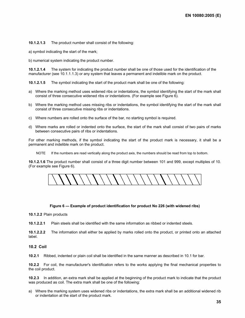
10.1.2.1.5 The symbol indicating the start of the product mark shall be one of the following:
a) Where the marking method uses widened ribs or indentations, the symbol identifying the start of the mark shall consist of three consecutive widened ribs or indentations. (For example see Figure 6).
b) Where the marking method uses missing ribs or indentations, the symbol identifying the start of the mark shall consist of three consecutive missing ribs or indentations.
c) Where numbers are rolled onto the surface of the bar, no starting symbol is required.
d) Where marks are rolled or indented onto the surface, the start of the mark shall consist of two pairs of marks between consecutive pairs of ribs or indentations.
For other marking methods, if the symbol indicating the start of the product mark is necessary, it shall be a permanent and indelible mark on the product.
NOTE If the numbers are read vertically along the product axis, the numbers should be read from top to bottom.
10.1.2.1.6 The product number shall consist of a three digit number between 101 and 999, except multiples of 10. (For example see Figure 6).
Figure 6 — Example of product identification for product No 226 (with widened ribs)
10.1.2.2 Plain products
10.1.2.2.1 Plain steels shall be identified with the same information as ribbed or indented steels.
10.1.2.2.2 The information shall either be applied by marks rolled onto the product, or printed onto an attached label.
10.2 Coil
10.2.1 Ribbed, indented or plain coil shall be identified in the same manner as described in 10.1 for bar.
10.2.2 For coil, the manufacturer's identification refers to the works applying the final mechanical properties to the coil product.
10.2.3 In addition, an extra mark shall be applied at the beginning of the product mark to indicate that the product was produced as coil. The extra mark shall be one of the following:
a) Where the marking system uses widened ribs or indentations, the extra mark shall be an additional widened rib or indentation at the start of the product mark.
EN 10080:2005 (E)
36
b) Where the marking system uses missing ribs or indentations, the extra mark shall be an additional missing rib or indentation at the start of the product mark.
c) Where the marking system uses numbers, the extra mark shall be a C.
d) Where the marking system uses marks rolled onto the surface, the extra mark shall be two marks between a pair of normal ribs, placed immediately prior to the start of the product number.
10.3 De-coiled product
10.3.1 In addition to the manufacturer's identification placed onto the product, an identification mark of the de-coiler shall be either made on the product or printed on an attached label.
10.3.2 The product number shall have been applied to the product prior to de-coiling by the rolling mill or the processor.
10.4 Welded fabric
In addition to the manufacturer's and product marks applied to the individual wires, a label shall be attached to a bundle of welded fabric to indicate the manufacturer of the welded fabric and the technical class(es) of the product.
10.5 Lattice girders
In addition to the manufacturer's and product marks applied to individual wires, a label shall be attached to the lattice girder to indicate the manufacturer of the lattice girder and the technical class(es) of the product.
11 Verification of mechanical properties in the case of dispute
11.1 Whenever the determination of a property specified in this European Standard as a characteristic value creates a dispute, the value shall be verified by selecting and testing three test pieces from various pieces from the batch under examination.
If one test result is less than the specified characteristic value both the test piece and the test method shall be carefully examined. If there is a local fault in the test piece or reason to believe that an error has occurred in the test, the test result shall be ignored. In this case a further single test shall be carried out.
If the three valid test results are equal to or greater than the specified characteristic value the batch shall be deemed to comply with this European Standard.
If not the requirements of 11.2 apply.
11.2 If 11.1 is not fulfilled, 10 additional test pieces shall be selected from different products in the batch.
The batch shall be deemed to comply with this European Standard if the average test result of the 10 test pieces is higher than the characteristic value and the individual values are higher than the minimum and lower than the maximum values of the relevant product specification. If not the batch is rejected.
EN 10080:2005 (E)
37
Annex A (informative)
Examples of weld points in lattice girder joints
Figure A.1
Figure A.2
Figure A.3
Figure A.4
Figure A.5
Figure A.6
Figure A.7
Figure A.8
Figure A.9
*Weld point
EN 10080:2005 (E)
38
Annex B (normative)
Test methods for lattice girders
B.1 General
The properties of the chords and diagonals shall be determined according to EN ISO 15630-1 except the dimensions (see B.2) and the shear force of joints which is described in B.3 to B.7.
B.2 Measurement of the dimensions of the lattice girder
B.2.1 Test piece
The test piece shall be a lattice girder in the as delivered condition.
B.2.2 Test equipment
The height, width and length of the lattice girder shall be measured with an instrument of a resolution of 1 mm or better.
B.2.3 Measuring procedure
The lattice girder shall be laid on a flat surface. The height and width shall be determined at the mid-length position of the lattice girder.
For the determination of the pitch, the distance over five pitches shall be measured and the average value calculated.
B.3 Shear test
B.3.1 Shear test on weld points
B.3.1.1 General
The same test method shall be used for type testing and factory production control.
B.3.1.2 Principle of the test methods
The strength of welds can be determined by either of two methods. The choice of method shall be at the discretion of the manufacturer.
Method 1
The principle of method 1 is a tensile test, which is applied on a chord of the lattice girder as shown in Figure B.1. In this test, the diagonal of the lattice girder is restrained.
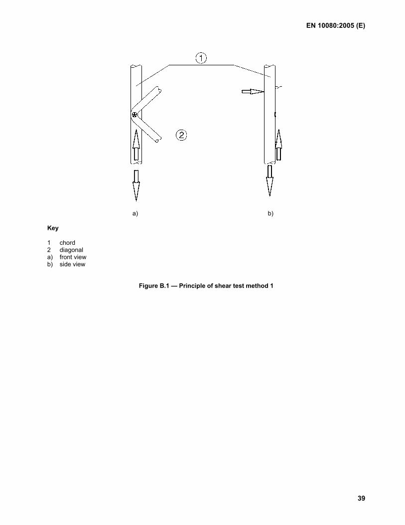
EN 10080:2005 (E)
39
a) b)
Key
1 chord 2 diagonal a) front view b) side view
Figure B.1 — Principle of shear test method 1
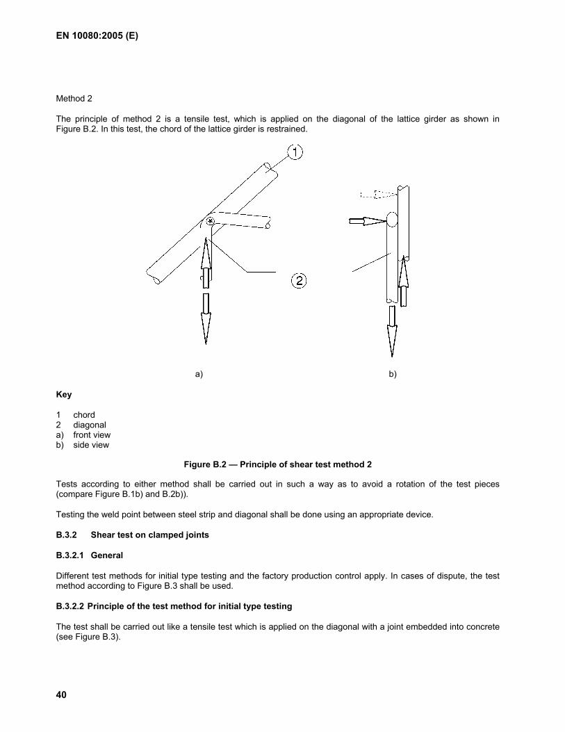
EN 10080:2005 (E)
40
Method 2
The principle of method 2 is a tensile test, which is applied on the diagonal of the lattice girder as shown in Figure B.2. In this test, the chord of the lattice girder is restrained.
a) b)
Key
1 chord 2 diagonal a) front view b) side view
Figure B.2 — Principle of shear test method 2
Tests according to either method shall be carried out in such a way as to avoid a rotation of the test pieces (compare Figure B.1b) and B.2b)).
Testing the weld point between steel strip and diagonal shall be done using an appropriate device.
B.3.2 Shear test on clamped joints
B.3.2.1 General
Different test methods for initial type testing and the factory production control apply. In cases of dispute, the test method according to Figure B.3 shall be used.
B.3.2.2 Principle of the test method for initial type testing
The test shall be carried out like a tensile test which is applied on the diagonal with a joint embedded into concrete (see Figure B.3).
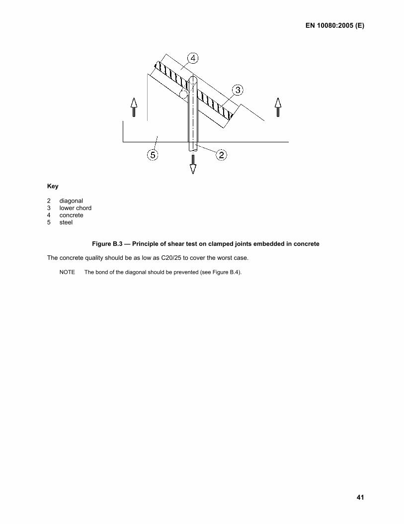
EN 10080:2005 (E)
41
Key
2 diagonal 3 lower chord 4 concrete 5 steel
Figure B.3 — Principle of shear test on clamped joints embedded in concrete
The concrete quality should be as low as C20/25 to cover the worst case.
NOTE The bond of the diagonal should be prevented (see Figure B.4).
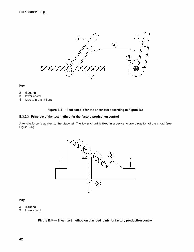
EN 10080:2005 (E)
42
Key
2 diagonal 3 lower chord 4 tube to prevent bond
Figure B.4 — Test sample for the shear test according to Figure B.3
B.3.2.3 Principle of the test method for the factory production control
A tensile force is applied to the diagonal. The lower chord is fixed in a device to avoid rotation of the chord (see Figure B.5).
Key
2 diagonal 3 lower chord
Figure B.5 — Shear test method on clamped joints for factory production control
EN 10080:2005 (E)
43
B.3.3 Test apparatus
B.3.3.1 Tensile testing machine
A tensile testing machine of class 1 or 0,5 according to EN ISO 7500-1 shall be used.
B.3.3.2 Holder
A special holder shall be used to support either the diagonal (method 1) or the chord (method 2). The holder shall be fixed in the upper jaws of the tensile testing machine.
In the case of method 1, the holder shall prevent the bending of the test piece during testing.
In the case of method 2, the holder shall prevent the rotation of the test piece during testing.
B.3.4 Test piece
The test piece shall be cut from the lattice girder without damaging the weld point.
B.3.5 Test procedure
The test piece shall be placed in the holder either before or after the holder is placed on the tensile testing machine.
The tensile force is applied on the free length of the test piece.
The stressing rate shall be the same as for tensile tests in the elastic range.
The maximum force Fw and the location of the fracture shall be recorded (see also 7.2.4.2.1).
EN 10080:2005 (E)
44
Annex C (informative)
Bond test for ribbed and indented reinforcing steel – Beam test
C.1 Scope
This Annex C specifies a method for testing the bond characteristics for ribbed and indented bars and wires to be used as reinforcing steel in concrete structures.
The beam test is intended to determine the bond of reinforcing steel and is to serve as a basis for the comparison of reinforcing bars and wires of approximately the same bar or wire diameter but with different surface configurations.
The test method is applicable for reinforcing steel in diameters ≤ 32 mm.
NOTE The method is based on the RILEM-Recommendation RC5, Bond test for reinforcement steel. 1. Beam test, 2. edition 1982.
C.2 Normative references
EN 1766, Products and systems for the protection and repair of concrete structures — Test methods — Reference concrete for testing
EN 12390-3, Testing hardened concrete — Part 3: Compressive strength of test specimens
C.3 Principle of the test
The principle of the test method is to load a test beam by simple flexure until complete bond failure of the reinforcing steel occurs in one of the half-beams or until the reinforcing steel itself fails. During loading, the slip of the two ends of the reinforcing steel is measured.
The beam used for the test consists of two parallelepipedal reinforced concrete blocks interconnected at the bottom by the reinforcing steel of which the bond is to be tested, and at the top by a steel hinge. The dimensions of the two blocks and the hinges are determined by the diameter of the reinforcing steel to be tested. The principle of the test is illustrated in Figures C.1 to C.4.
The dimensions of the test beams depend on the nominal diameter of the reinforcing steel for which bond is to be determined. For nominal diameters less than 16 mm, a beam specimen of type A is used and for nominal diameters equal to or larger than 16 mm, a beam specimen of type B is used, see Figures C.3 and C.4.
NOTE The experience of testing bars with diameters larger than 32 mm is limited. To use the test method of this annex for such large diameters a type testing program should be performed to evaluate the applicability of the test method.
C.4 Samples and specimens
If various sizes of the same technical class of reinforcing steel and the same surface configuration are to be tested they may be grouped into series. All diameters (sizes) within a group shall have the same configuration with regard to ribs or indentations. A grouping is shown in Table C.1.
NOTE To have the same surface configuration implies that the relationship between rib height/bar or wire diameter and rib spacing/bar or wire diameter as well as the rib inclination are the same. A similar definition applies to reinforcing steels with indentations.
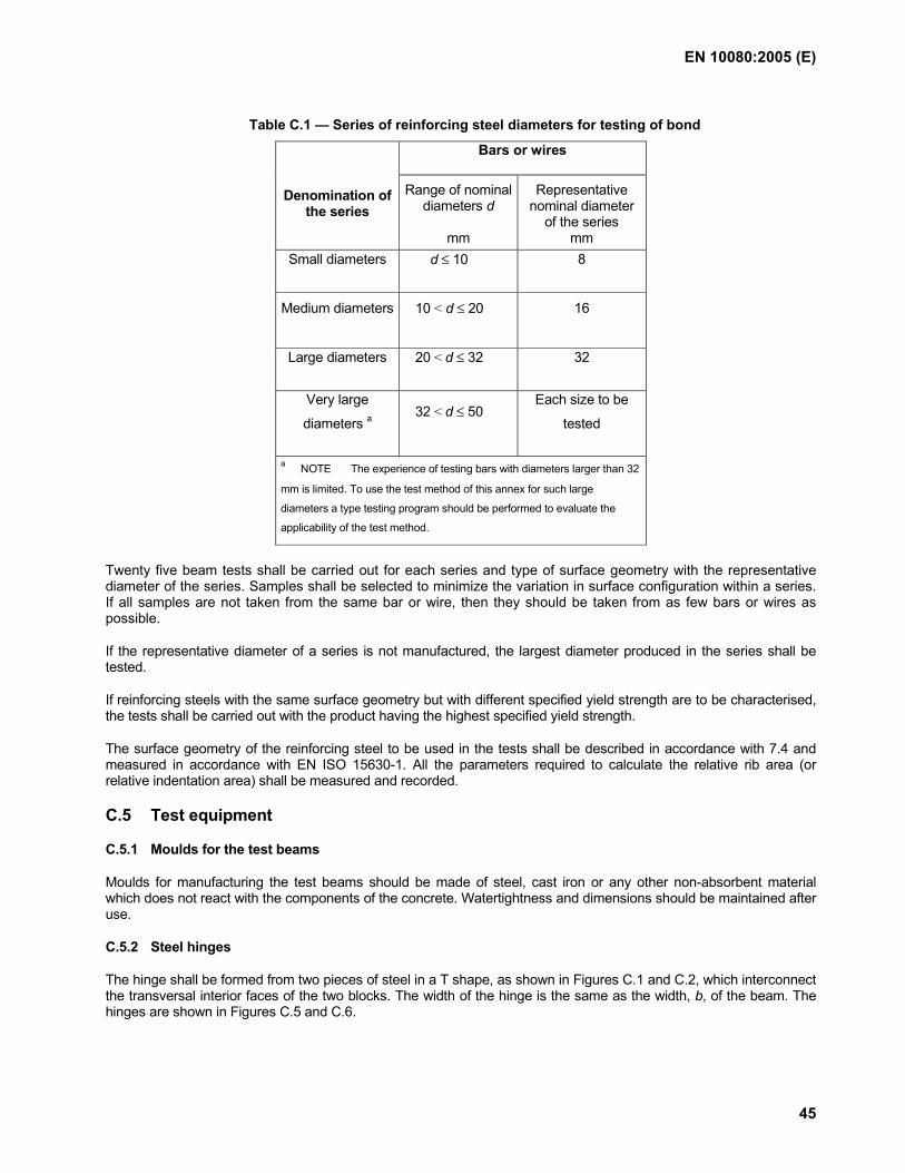
EN 10080:2005 (E)
45
Table C.1 — Series of reinforcing steel diameters for testing of bond
Bars or wires
Denomination of the series
Range of nominal diameters d
mm
Representative nominal diameter
of the series mm
Small diameters d ≤ 10 8
Medium diameters 10 < d ≤ 20 16
Large diameters 20 < d ≤ 32 32
Very large
diameters a 32 < d ≤ 50
Each size to be
tested
a NOTE The experience of testing bars with diameters larger than 32
mm is limited. To use the test method of this annex for such large
diameters a type testing program should be performed to evaluate the
applicability of the test method.
Twenty five beam tests shall be carried out for each series and type of surface geometry with the representative diameter of the series. Samples shall be selected to minimize the variation in surface configuration within a series. If all samples are not taken from the same bar or wire, then they should be taken from as few bars or wires as possible.
If the representative diameter of a series is not manufactured, the largest diameter produced in the series shall be tested.
If reinforcing steels with the same surface geometry but with different specified yield strength are to be characterised, the tests shall be carried out with the product having the highest specified yield strength.
The surface geometry of the reinforcing steel to be used in the tests shall be described in accordance with 7.4 and measured in accordance with EN ISO 15630-1. All the parameters required to calculate the relative rib area (or relative indentation area) shall be measured and recorded.
C.5 Test equipment
C.5.1 Moulds for the test beams
Moulds for manufacturing the test beams should be made of steel, cast iron or any other non-absorbent material which does not react with the components of the concrete. Watertightness and dimensions should be maintained after use.
C.5.2 Steel hinges
The hinge shall be formed from two pieces of steel in a T shape, as shown in Figures C.1 and C.2, which interconnect the transversal interior faces of the two blocks. The width of the hinge is the same as the width, b, of the beam. The hinges are shown in Figures C.5 and C.6.
EN 10080:2005 (E)
46
C.5.3 System for regulating forces
The mechanism for applying forces should be fitted with a system for regulating forces which enables them to be increased continuously, within the limits described in C.5.5.
C.5.4 Force application system
The system for applying forces shall ensure that the force is applied perpendicular to the face of the beam specimen.
The mechanism for applying forces shall consist of steel rotating knife-edges or roller bearings; two to support the beam specimen and another two for loading.
C.5.5 Instruments for measuring forces
Forces shall be measured with an accuracy of at least 1 % of the maximum force obtained in the test.
The reading device shall have an indication of the maximum force reached during the test.
C.5.6 Instruments for measuring slip
The instruments for measuring slip shall be accurate to ± 0,01 mm.
C.6 Preparation of samples
C.6.1 Reinforcing steel to be tested
The test bar shall be in the "as manufactured" condition without loose millscale, preferably entirely free from rust and, if necessary, carefully degreased with an appropriate degreasing product, e.g. carbon tetrachloride (CCI4) or ethylene trichloride (C2HCI3). The test bar shall be without any machining. If the test bar is corroded, the conditions of the bar shall be described in the test report and possibly supported by photographs of the surface.
The bar shall not be cleaned in any way that might change its roughness.
The test pieces taken from coils shall have been straightened prior to testing according to EN ISO 15630-1:2002, Clause 4.
C.6.2 Auxiliary reinforcement
Auxiliary reinforcement should have the same strength and surface characteristics as the reinforcing steel to be tested. Figures C.5 and C.6 detail the components for the auxiliary reinforcement.
C.6.3 Plastic sleeves
Sleeves used to avoid the adherence of the concrete to the reinforcing steel to be tested shall be of plastic. These sleeves shall be rigid so as not to become deformed during the test.
C.6.4 Concrete
C.6.4.1 General
The concrete for the beam specimen as well as the cylindrical test pieces shall be produced, placed and stored according to EN 1766 with the qualifications given in C.6.4.2.
C.6.4.2 Strength class of concrete
The concrete shall be either of Type C(0,70) with a compressive strength target value of (25 ± 5) MPa, or of Type C(0,45) with a compressive strength target value of (50 ± 5) MPa, measured on 150 mm × 300 mm cylindrical specimen and tested according to EN 12390-3.
If not otherwise agreed the tests shall be performed with concrete Type C(0,70).
EN 10080:2005 (E)
47
NOTE It is recommended that the test pieces for 25 tests are prepared in 5 lots or mixes, making 5 specimens from each lot.
C.7 Execution of the tests
The test beam resting on two rotating knife-edges or rolling bearings, is loaded by two forces of equal magnitude, disposed symmetrically with regard to mid-span and likewise applied through movable knife-edges or rollers.
Compressive strength of concrete shall be in the range given in C.6.4.2. The age of the concrete shall not be less than 21 d and not more than 35 d.
Loading shall be applied in consecutive increments corresponding to stresses, σs, in the bar or wire equal to 0 - 80 -160 - 240, etc., MPa. For each increment, the total force applied to the test piece is given by one of the following expressions:
where An denotes the nominal cross-sectional area of the reinforcing steel. Smaller increments may also be used. Alternatively the force - slip data may be logged continously by electronic devices, using a loading speed not exceeding a corresponding stressing rate increase of 1 MPa/s in the reinforcing steel.
The force increase, at each stage, shall be gradual and continuous. Each increment shall be reached in half a minute and the force shall be maintained long enough to stabilize the slip, or, at the most, for two minutes.
The slip shall be measured at the beginning and at the end of each increment in loading.
The test shall continue until complete bond failure of the bar or wire occurs in both half-beams or until the bar or wire itself fails. Bond failure generally does not take place simultaneously in the two half-beams. For this reason, when the half-bar or wire whose bond has failed attains a slip of 3 mm, this half-bar shall be held in a gripping device which bears against the concrete and prevents any further slip.
Force-slip curves may be either recorded automatically, or plotted point by point from dial gauge readings.
C.8 Test results
C.8.1 Calculation of the bond stress
If the total force applied to the test beam is Fa, for a given slip, the bond stress, τb, is given by:
where
σs is the stress of the bar, given by one of the following formulae:
mm 16 for1,25
n
a <dA
Fσ
= s (C.4)
mm 16 for1,50
n
a ≥dA
Fσ
= s (C.5)
mm 16for1,25
sna < = dσ x AF (C.1)
mm 16for1,50
sna = ≥dσ xA
F (C.2)
40σ s
b =τ (C.3)
EN 10080:2005 (E)
48
C.8.2 Values of bond stress
The bond stress shall be calculated for 4 measured slip values:
τ0,01 = Bond stress at 0,01 mm slip;
τ0,1 = Bond stress at 0,1 mm slip;
τ1 = Bond stress at 1 mm slip;
τbu = Bond stress at maximum force.
Other values may be agreed between the parties.
To obtain the 4 values of slip, force-slip curves shall be recorded, and made available on request.
C.9 Test report
The laboratory shall issue a report which shall contain the following information:
a) identification of the laboratory;
b) identification of the manufacturer of the product tested;
c) product number;
d) technical class of the reinforcing steel with reference to the product specification;
e) number of this document and type of test method;
f) nominal diameters tested and the series they represent;
g) surface geometry of the specimen, i.e. rib/indentation heights, rib/indentation spacing, rib/indentation inclinations and relative rib/indentation area;
h) strength class of the concrete, i.e. Type C(0,70) or Type C(0,45) according to EN 1766;
i) compressive strength of the concrete at the date of testing;
k) dates of the tests;
l) all single test results;
m) description of the failure mode;
n) force-slip curves.
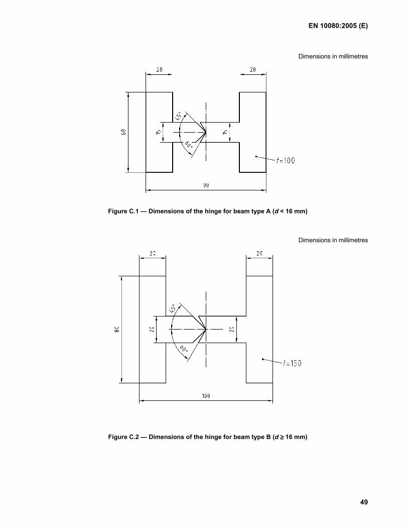
EN 10080:2005 (E)
49
Dimensions in millimetres
Figure C.1 — Dimensions of the hinge for beam type A (d < 16 mm)
Dimensions in millimetres
Figure C.2 — Dimensions of the hinge for beam type B (d ≥≥≥≥ 16 mm)
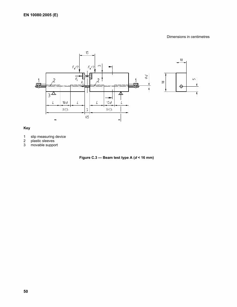
EN 10080:2005 (E)
50
Dimensions in centimetres
Key
1 slip measuring device 2 plastic sleeves 3 movable support
Figure C.3 — Beam test type A (d < 16 mm)
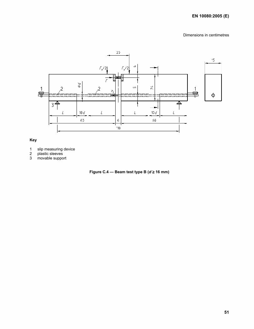
EN 10080:2005 (E)
51
Dimensions in centimetres
Key
1 slip measuring device 2 plastic sleeves 3 movable support
Figure C.4 — Beam test type B (d ≥≥≥≥ 16 mm)
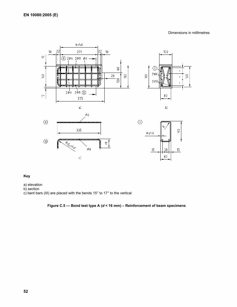
EN 10080:2005 (E)
52
Dimensions in millimetres
Key
a) elevation b) section c) bent bars (III) are placed with the bends 15° to 17° to the vertical
Figure C.5 — Bond test type A (d < 16 mm) – Reinforcement of beam specimens
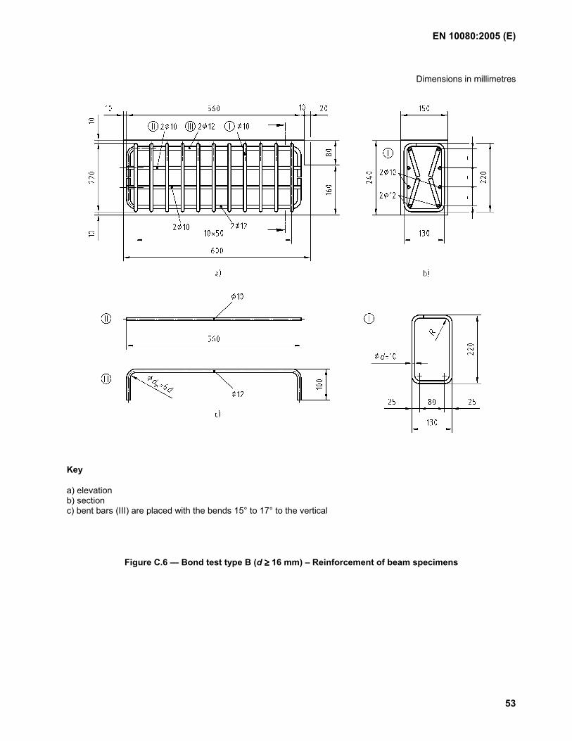
EN 10080:2005 (E)
53
Dimensions in millimetres
Key
a) elevation b) section c) bent bars (III) are placed with the bends 15° to 17° to the vertical
Figure C.6 — Bond test type B (d ≥≥≥≥ 16 mm) – Reinforcement of beam specimens
EN 10080:2005 (E)
54
Annex D (informative)
Bond test for ribbed and indented reinforcing steel – Pull-out test
D.1 Scope
This Annex D specifies a method for testing the bond characteristics for ribbed and indented bars and wires to be used as reinforcement in concrete structures.
The pull-out test is intended to determine the bond of reinforcing steel and is to serve as a basis for the comparison of reinforcing bars and wires of approximately the same bar or wire diameter but with different surface configurations.
The test method is applicable for reinforcing steel in diameters ≤ 32 mm.
NOTE The method is based on the RILEM-recommendation RC 6 Bond test for reinforcement steel – 2. Pull-out test, 1983.
D.2 Normative references
EN 1766, Products and systems for the protection and repair of concrete structures — Test methods - Reference concrete for testing
EN 12390-3, Testing of hardened concrete — Part 3: Compressive strength of test specimens
D.3 Principle of the test
The principle of the test is to load a bar or wire that is incorporated in a concrete cube, along a defined length, by a tensile force. The other end of the bar remains without stress. The relation between the tensile force and the slip (i.e. the relative displacement between steel and concrete) is measured up to failure. The force is increased up to failure of the bond or until the reinforcement itself fails. The principle of the test is illustrated in Figure D.1.
The test specimen is a cube of concrete where the bar or wire is located in the center of the cube. The effective bond length of the bar or wire is 5 d and corresponds only to a part of the specimen. In the other part of the bar or wire bond is prevented. The bar or wire to be tested extends beyond the two sides of the specimen; the tension is applied to the longer end, and the device for measuring the slip is set on the shorter end. Figure D.1 shows the test specimen.
The sleeves shall fit with about 1 mm tolerance around the bar or wire and its thickness shall not exceed 2 mm.
NOTE The experience of testing bars with diameters larger than 32 mm is limited. To use the test method of this annex for such large diameters a type testing program should be performed to evaluate the applicability of the test method.
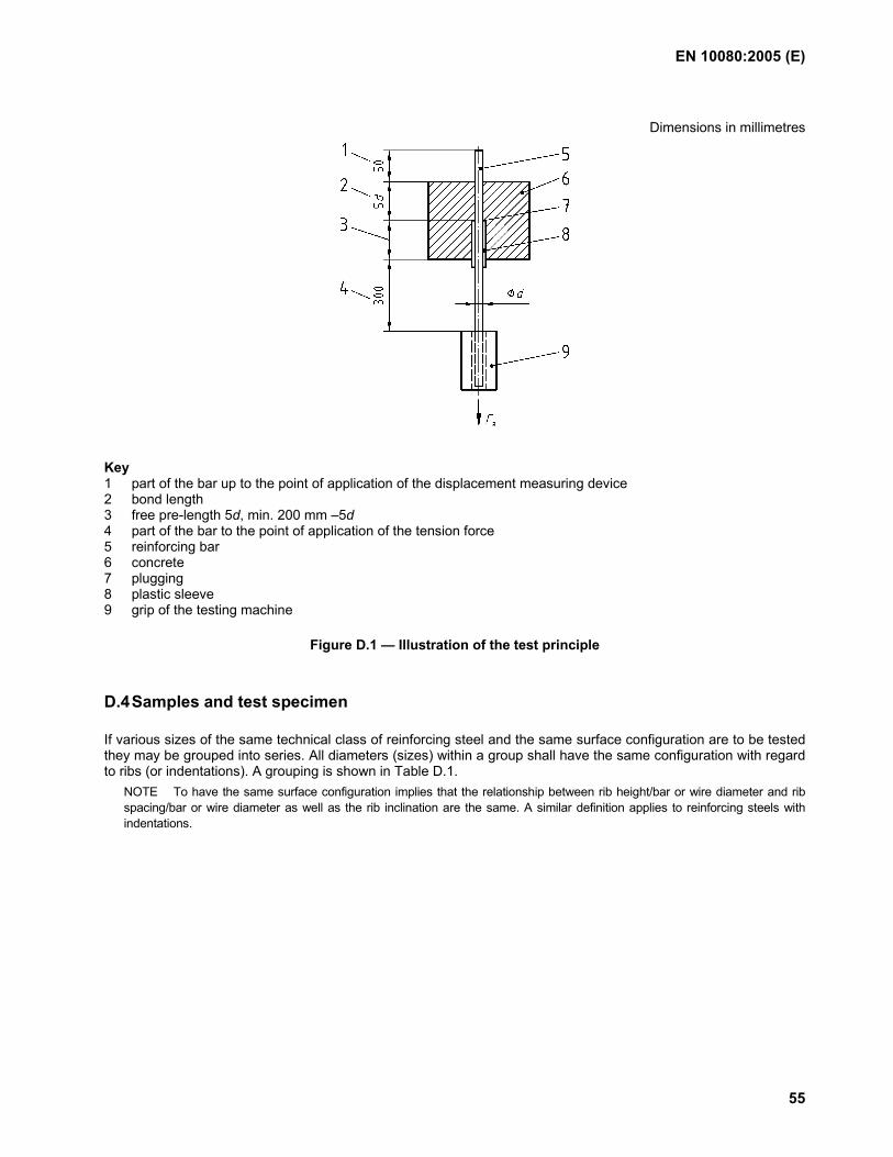
EN 10080:2005 (E)
55
Dimensions in millimetres
Key 1 part of the bar up to the point of application of the displacement measuring device 2 bond length 3 free pre-length 5d, min. 200 mm –5d 4 part of the bar to the point of application of the tension force 5 reinforcing bar 6 concrete 7 plugging 8 plastic sleeve 9 grip of the testing machine
Figure D.1 — Illustration of the test principle
D.4 Samples and test specimen
If various sizes of the same technical class of reinforcing steel and the same surface configuration are to be tested they may be grouped into series. All diameters (sizes) within a group shall have the same configuration with regard to ribs (or indentations). A grouping is shown in Table D.1.
NOTE To have the same surface configuration implies that the relationship between rib height/bar or wire diameter and rib spacing/bar or wire diameter as well as the rib inclination are the same. A similar definition applies to reinforcing steels with indentations.
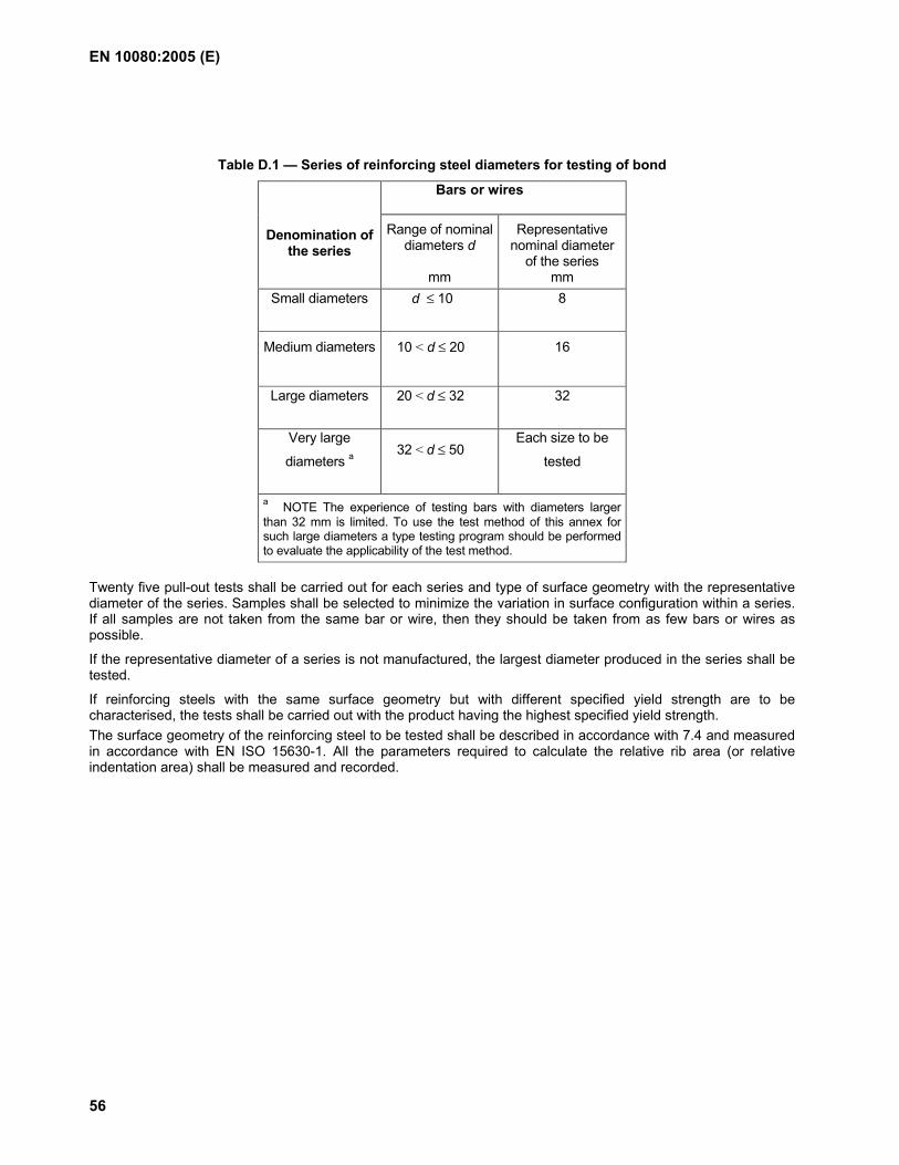
EN 10080:2005 (E)
56
Table D.1 — Series of reinforcing steel diameters for testing of bond
Bars or wires
Denomination of the series
Range of nominal diameters d
mm
Representative nominal diameter
of the series mm
Small diameters d ≤ 10 8
Medium diameters 10 < d ≤ 20 16
Large diameters 20 < d ≤ 32 32
Very large
diameters a 32 < d ≤ 50
Each size to be
tested
a NOTE The experience of testing bars with diameters larger than 32 mm is limited. To use the test method of this annex for such large diameters a type testing program should be performed to evaluate the applicability of the test method.
Twenty five pull-out tests shall be carried out for each series and type of surface geometry with the representative diameter of the series. Samples shall be selected to minimize the variation in surface configuration within a series. If all samples are not taken from the same bar or wire, then they should be taken from as few bars or wires as possible.
If the representative diameter of a series is not manufactured, the largest diameter produced in the series shall be tested.
If reinforcing steels with the same surface geometry but with different specified yield strength are to be characterised, the tests shall be carried out with the product having the highest specified yield strength. The surface geometry of the reinforcing steel to be tested shall be described in accordance with 7.4 and measured in accordance with EN ISO 15630-1. All the parameters required to calculate the relative rib area (or relative indentation area) shall be measured and recorded.
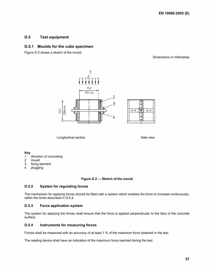
EN 10080:2005 (E)
57
D.5 Test equipment
D.5.1 Moulds for the cube specimen
Figure D.2 shows a sketch of the mould. Dimensions in millimetres
Longitudinal section Side view
Key 1 direction of concreting 2 mould 3 fixing element 4 plugging
Figure D.2 — Sketch of the mould
D.5.2 System for regulating forces
The mechanism for applying forces should be fitted with a system which enables the force to increase continuously, within the limits described in D.5.4.
D.5.3 Force application system
The system for applying the forces shall ensure that the force is applied perpendicular to the face of the concrete surface.
D.5.4 Instruments for measuring forces
Forces shall be measured with an accuracy of at least 1 % of the maximum force obtained in the test.
The reading device shall have an indication of the maximum force reached during the test.
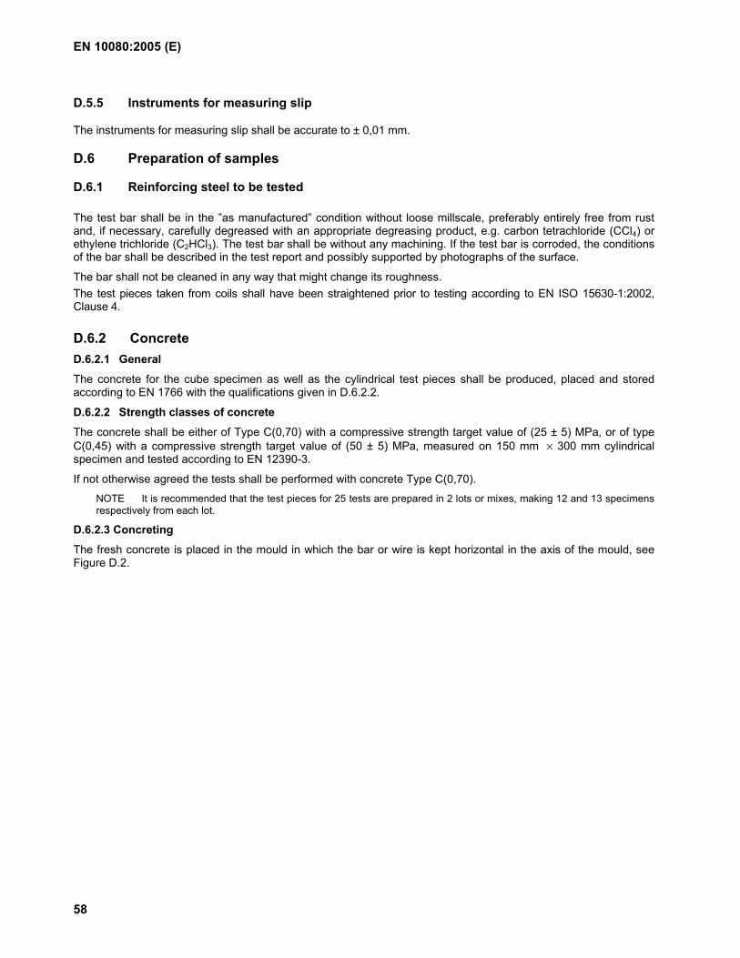
EN 10080:2005 (E)
58
D.5.5 Instruments for measuring slip
The instruments for measuring slip shall be accurate to ± 0,01 mm.
D.6 Preparation of samples
D.6.1 Reinforcing steel to be tested
The test bar shall be in the ”as manufactured” condition without loose millscale, preferably entirely free from rust and, if necessary, carefully degreased with an appropriate degreasing product, e.g. carbon tetrachloride (CCl4) or ethylene trichloride (C2HCl3). The test bar shall be without any machining. If the test bar is corroded, the conditions of the bar shall be described in the test report and possibly supported by photographs of the surface.
The bar shall not be cleaned in any way that might change its roughness. The test pieces taken from coils shall have been straightened prior to testing according to EN ISO 15630-1:2002, Clause 4.
D.6.2 Concrete D.6.2.1 General
The concrete for the cube specimen as well as the cylindrical test pieces shall be produced, placed and stored according to EN 1766 with the qualifications given in D.6.2.2.
D.6.2.2 Strength classes of concrete
The concrete shall be either of Type C(0,70) with a compressive strength target value of (25 ± 5) MPa, or of type C(0,45) with a compressive strength target value of (50 ± 5) MPa, measured on 150 mm × 300 mm cylindrical specimen and tested according to EN 12390-3.
If not otherwise agreed the tests shall be performed with concrete Type C(0,70).
NOTE It is recommended that the test pieces for 25 tests are prepared in 2 lots or mixes, making 12 and 13 specimens respectively from each lot.
D.6.2.3 Concreting
The fresh concrete is placed in the mould in which the bar or wire is kept horizontal in the axis of the mould, see Figure D.2.
EN 10080:2005 (E)
59
D.7 Execution of the test
D.7.1 Testing machine
The test set-up is shown in Figure D.3
The force range of the testing machine should be suitable for the expected failure force of the test piece.
Key 1 slip measuring device for ∆o 2 specimen 3 steel plate, 10 mm thick 4 tension force 5 bearing plate 6 5 mm rubber supporting plate
Figure D.3 — Set up of the testing machine
D.7.2 Testing procedure
The specimen is placed vertically on the bearing plate, provided with a central 2 d cavity, of the tension device. The tension force (Fa) is applied to the longer end of the sample. The slip shall be measured at the beginning and at the end of each increment in loading.
EN 10080:2005 (E)
60
D.7.3 Loading rate The loading rate vp shall be determined for each bar or wire diameter in order that the rate of increase of the bond stress is constant. The value vp = 0,56 d2 (N/s), should be aimed at where d is the nominal bar or wire diameter in mm.
D.8 Test results
The tension forces Fa measured in the test shall be transformed into bond stresses by the following formula:
c
cmadm f
f
d
F25
1π
τ = (D.1)
where
fcm is the target value of the strengh class i.e. 25 MPa or 50 MPa, depending on the intended type of concrete;
fc is the average of concrete strength of the test specimens
both according to D.6.2.
The pull-out test on one specimen gives the relation
τdm = f(∆o)
where
∆o is the slip measured under the tension force Fa. The force-slip curves of all individual test results obtained serve as the basis for judgement of the bond.
D.9 Test report
The laboratory shall issue a report which shall contain the following information:
a) identification of the laboratory;
b) identification of the manufacturer of the product tested;
c) product number;
d) technical class of the reinforcing steel with reference to the product specification;
e) number of this document and type of test method;
f) nominal diameters tested and the series they represent;
g) surface geometry of the tested specimen, i.e. rib/indentation heights, rib/indentation spacing, rib/indentation inclinations and relative rib/indentation area;
h) strength class of the concrete, i.e. Type C(0,70) or Type C(0,45) according to EN 1766;
i) compressive strength of the concrete at the date of the testing;
k) dates of the tests;
l) all single test results of the calculated values of bond stress τdm and the individual curves of force-slip relations;
m) description of the failure mode.
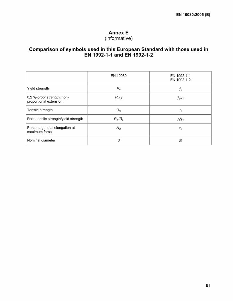
EN 10080:2005 (E)
61
Annex E (informative)
Comparison of symbols used in this European Standard with those used in
EN 1992-1-1 and EN 1992-1-2
EN 10080 EN 1992-1-1 EN 1992-1-2
Yield strength Re ƒy
0,2 %-proof strength, non-proportional extension
Rp0,2 ƒp0,2
Tensile strength Rm ƒt
Ratio tensile strength/yield strength Rm/Re ƒt/ƒy
Percentage total elongation at maximum force
Agt εu
Nominal diameter d ∅
EN 10080:2005 (E)
62
Annex ZA (informative)
Clauses of this European Standard addressing the provisions of the EU
Construction Products Directive
ZA.1 Scope and relevant characteristics
This European Standard has been prepared under a mandate M/115 [Reinforcing and prestressing steel (for concrete)] given to CEN by the European Commission and the European Free Trade Association.
The clauses of this European Standard shown in this annex meet the requirements of the mandate given under the EU Construction Products Directive (89/106/EEC).
Compliance with these clauses confers a presumption of fitness of the reinforcing steel covered by this annex for the intended uses indicated herein; reference shall be made to the information accompanying the CE marking.
WARNING: Other requirements and other EU Directives, not affecting the fitness for intended uses, may be applicable to the reinforcing steel falling within the scope of this European Standard.
NOTE 1 In addition to any specific clauses relating to dangerous substances contained in this standard, there may be other requirements applicable to the products falling within its scope (e.g. transposed European legislation and national laws, regulations and administrative provisions). In order to meet the provisions of the EU Construction Products Directive, these requirements need also to be complied with, when and where they apply.
NOTE 2 An informative database of European and national provisions on dangerous substances is available at the Construction web site on EUROPA (accessed through http://europa.eu.int/comm/enterprise/construction/internal/dangsub/dangmain.htm ).
This annex establishes the conditions for the CE marking of the reinforcing steel intended for the uses indicated in Table ZA.1 and shows the relevant clauses applicable:
This annex has the same scope as Clause 1 of this standard and is identified in Table ZA.1.
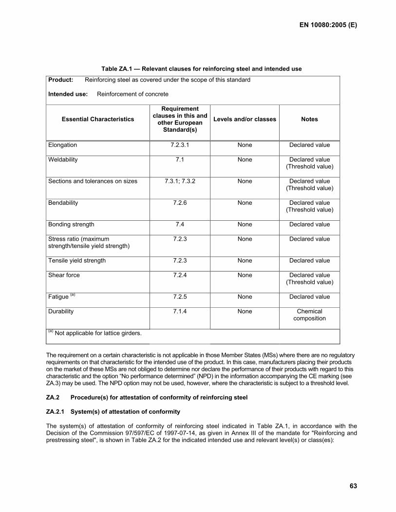
EN 10080:2005 (E)
63
Table ZA.1 — Relevant clauses for reinforcing steel and intended use
Product: Reinforcing steel as covered under the scope of this standard
Intended use: Reinforcement of concrete
Essential Characteristics Requirement
clauses in this and other European
Standard(s) Levels and/or classes Notes
Elongation 7.2.3.1 None Declared value
Weldability 7.1 None Declared value (Threshold value)
Sections and tolerances on sizes 7.3.1; 7.3.2 None Declared value (Threshold value)
Bendability 7.2.6 None Declared value (Threshold value)
Bonding strength 7.4 None Declared value
Stress ratio (maximum strength/tensile yield strength)
7.2.3 None Declared value
Tensile yield strength 7.2.3 None Declared value
Shear force 7.2.4 None Declared value (Threshold value)
Fatigue (a) 7.2.5 None Declared value
Durability 7.1.4 None Chemical composition
(a) Not applicable for lattice girders.
The requirement on a certain characteristic is not applicable in those Member States (MSs) where there are no regulatory requirements on that characteristic for the intended use of the product. In this case, manufacturers placing their products on the market of these MSs are not obliged to determine nor declare the performance of their products with regard to this characteristic and the option “No performance determined” (NPD) in the information accompanying the CE marking (see ZA.3) may be used. The NPD option may not be used, however, where the characteristic is subject to a threshold level.
ZA.2 Procedure(s) for attestation of conformity of reinforcing steel
ZA.2.1 System(s) of attestation of conformity
The system(s) of attestation of conformity of reinforcing steel indicated in Table ZA.1, in accordance with the Decision of the Commission 97/597/EC of 1997-07-14, as given in Annex III of the mandate for "Reinforcing and prestressing steel", is shown in Table ZA.2 for the indicated intended use and relevant level(s) or class(es):
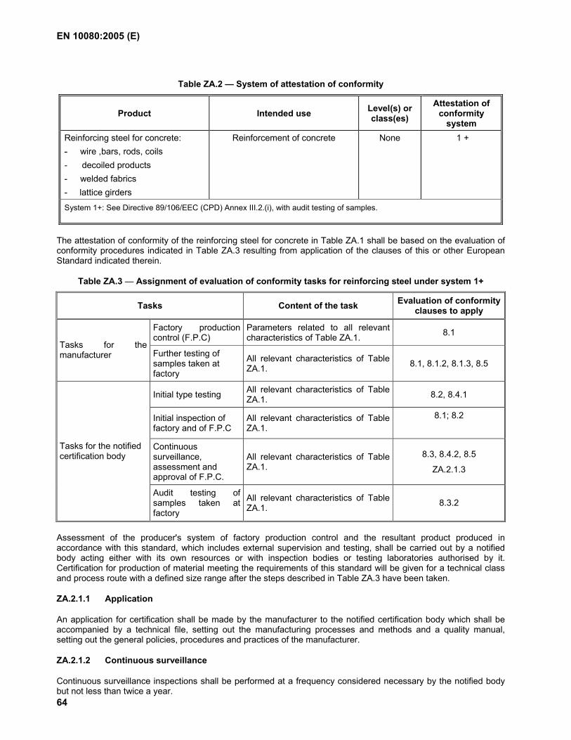
EN 10080:2005 (E)
64
Table ZA.2 — System of attestation of conformity
Product Intended use Level(s) or class(es)
Attestation of conformity
system Reinforcing steel for concrete: - wire ,bars, rods, coils - decoiled products - welded fabrics - lattice girders
Reinforcement of concrete None 1 +
System 1+: See Directive 89/106/EEC (CPD) Annex III.2.(i), with audit testing of samples.
The attestation of conformity of the reinforcing steel for concrete in Table ZA.1 shall be based on the evaluation of conformity procedures indicated in Table ZA.3 resulting from application of the clauses of this or other European Standard indicated therein.
Table ZA.3 — Assignment of evaluation of conformity tasks for reinforcing steel under system 1+
Tasks Content of the task Evaluation of conformity clauses to apply
Factory production control (F.P.C)
Parameters related to all relevant characteristics of Table ZA.1. 8.1
Tasks for the manufacturer Further testing of
samples taken at factory
All relevant characteristics of Table ZA.1. 8.1, 8.1.2, 8.1.3, 8.5
Initial type testing All relevant characteristics of Table ZA.1. 8.2, 8.4.1
Initial inspection of factory and of F.P.C
All relevant characteristics of Table ZA.1.
8.1; 8.2
Continuous surveillance, assessment and approval of F.P.C.
All relevant characteristics of Table ZA.1.
8.3, 8.4.2, 8.5
ZA.2.1.3
Tasks for the notified certification body
Audit testing of samples taken at factory
All relevant characteristics of Table ZA.1. 8.3.2
Assessment of the producer's system of factory production control and the resultant product produced in accordance with this standard, which includes external supervision and testing, shall be carried out by a notified body acting either with its own resources or with inspection bodies or testing laboratories authorised by it. Certification for production of material meeting the requirements of this standard will be given for a technical class and process route with a defined size range after the steps described in Table ZA.3 have been taken.
ZA.2.1.1 Application
An application for certification shall be made by the manufacturer to the notified certification body which shall be accompanied by a technical file, setting out the manufacturing processes and methods and a quality manual, setting out the general policies, procedures and practices of the manufacturer.
ZA.2.1.2 Continuous surveillance
Continuous surveillance inspections shall be performed at a frequency considered necessary by the notified body but not less than twice a year.
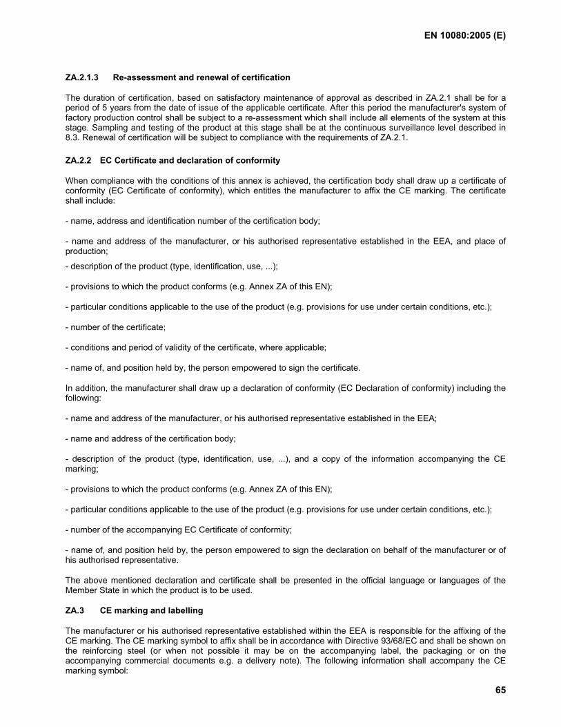
EN 10080:2005 (E)
65
ZA.2.1.3 Re-assessment and renewal of certification
The duration of certification, based on satisfactory maintenance of approval as described in ZA.2.1 shall be for a period of 5 years from the date of issue of the applicable certificate. After this period the manufacturer's system of factory production control shall be subject to a re-assessment which shall include all elements of the system at this stage. Sampling and testing of the product at this stage shall be at the continuous surveillance level described in 8.3. Renewal of certification will be subject to compliance with the requirements of ZA.2.1.
ZA.2.2 EC Certificate and declaration of conformity
When compliance with the conditions of this annex is achieved, the certification body shall draw up a certificate of conformity (EC Certificate of conformity), which entitles the manufacturer to affix the CE marking. The certificate shall include:
- name, address and identification number of the certification body;
- name and address of the manufacturer, or his authorised representative established in the EEA, and place of production;
- description of the product (type, identification, use, ...);
- provisions to which the product conforms (e.g. Annex ZA of this EN);
- particular conditions applicable to the use of the product (e.g. provisions for use under certain conditions, etc.);
- number of the certificate;
- conditions and period of validity of the certificate, where applicable;
- name of, and position held by, the person empowered to sign the certificate.
In addition, the manufacturer shall draw up a declaration of conformity (EC Declaration of conformity) including the following:
- name and address of the manufacturer, or his authorised representative established in the EEA;
- name and address of the certification body;
- description of the product (type, identification, use, ...), and a copy of the information accompanying the CE marking;
- provisions to which the product conforms (e.g. Annex ZA of this EN);
- particular conditions applicable to the use of the product (e.g. provisions for use under certain conditions, etc.);
- number of the accompanying EC Certificate of conformity;
- name of, and position held by, the person empowered to sign the declaration on behalf of the manufacturer or of his authorised representative.
The above mentioned declaration and certificate shall be presented in the official language or languages of the Member State in which the product is to be used.
ZA.3 CE marking and labelling
The manufacturer or his authorised representative established within the EEA is responsible for the affixing of the CE marking. The CE marking symbol to affix shall be in accordance with Directive 93/68/EC and shall be shown on the reinforcing steel (or when not possible it may be on the accompanying label, the packaging or on the accompanying commercial documents e.g. a delivery note). The following information shall accompany the CE marking symbol:
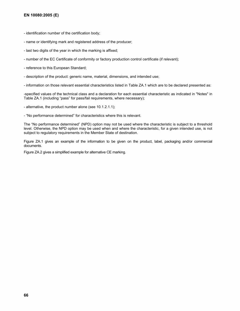
EN 10080:2005 (E)
66
- identification number of the certification body;
- name or identifying mark and registered address of the producer;
- last two digits of the year in which the marking is affixed;
- number of the EC Certificate of conformity or factory production control certificate (if relevant);
- reference to this European Standard;
- description of the product: generic name, material, dimensions, and intended use;
- information on those relevant essential characteristics listed in Table ZA.1 which are to be declared presented as:
-specified values of the technical class and a declaration for each essential characteristic as indicated in "Notes" in Table ZA.1 (including “pass” for pass/fail requirements, where necessary);
- alternative, the product number alone (see 10.1.2.1.1);
- “No performance determined” for characteristics where this is relevant.
The “No performance determined” (NPD) option may not be used where the characteristic is subject to a threshold level. Otherwise, the NPD option may be used when and where the characteristic, for a given intended use, is not subject to regulatory requirements in the Member State of destination.
Figure ZA.1 gives an example of the information to be given on the product, label, packaging and/or commercial documents.
Figure ZA.2 gives a simplified example for alternative CE marking.
EN 10080:2005 (E)
67
01234
CE conformity marking, consisting of the “CE”-symbol given in Directive
93/68/EEC.
Identification number of the certification body
AnyCo Ltd, PO Box 21, B-1050
05
01234-CPD-00234
Name or identifying mark and registered address of the producer
Last two digits of the year in which the marking was affixed
Certificate number
EN 10080 xxx
Product number 226
Reinforcing steel, intended to be used for reinforcement of concrete
Bar - 8 x 12000
Elongation : Agt 5 %
Weldability : Ceq = 0,52
Sections: 8 mm Tolerances: pass
Bendability : pass
Bonding strength: pass (surface geometry)
Stress ratio Rm/Re: 1,08
Tensile yield strength: 500 MPa
Fatigue: NPD
Durability: C=0,24;S=0,055;P=0,055;N=0,014;Cu=0,85;Ceq= 0,52
No. of European Standard Product specification
Product number Description of product
and information on regulated characteristics
NOTE The declared values in the above example are the specified performance characteristics of a theoretical technical class with product number 226 according to a product specification xxx.
Figure ZA.1 — Example CE marking information
EN 10080:2005 (E)
68
01234
CE conformity marking, consisting of the “CE”-symbol given in Directive
93/68/EEC.
Identification number of the certification body
AnyCo Ltd, PO Box 21, B-1050
05
01234-CPD-00234
Name or identifying mark and registered address of the producer
Last two digits of the year in which the marking was affixed
Certificate number
EN 10080 xxx
Product number 226
Reinforcing steel, intended to be used for reinforcement of concrete
Bar - 8 x 12000
No. of European Standard Product specification
Product number Description of product
and information on regulated characteristics
NOTE This figure is a simplified form of CE marking information of a theoretical technical class with product number 226 according to a product specification xxx.
Figure ZA.2 — Simplified example CE marking information
In addition to any specific information relating to dangerous substances shown above, the product should also be accompanied, when and where required and in the appropriate form, by documentation listing any other legislation on dangerous substances for which compliance is claimed, together with any information required by that legislation.
NOTE European legislation without national derogations need not be mentioned.
EN 10080:2005 (E)
69
Bibliography
[1] EN 1992-1-1, Eurocode 2: Design of concrete structures — Part 1-1: General rules and rules for buildings
[2] EN 1992-1-2, Eurocode 2: Design of concrete structures — Part 1-2: General rules - Structural fire design
[3] prEN 10138-1, Prestressing steels — Part 1: General requirements
[4] prEN 10138-2, Prestressing steels — Part 2: Wire
[5] prEN 10138-3, Prestressing steels — Part 3: Strand
[6] prEN 10138-4, Prestressing steels — Part 4: Bars
[7] EN 12390-2, Testing hardened concrete — Part 2: Making and curing specimens for strength tests
[8] EN ISO 9001, Quality management systems — Requirements (ISO 9001:2000)
[9] prEN ISO 17660, Welding of reinforcing steels
BS EN 10080:2005
BSI
389 Chiswick High Road
London
W4 4AL
BSI — British Standards InstitutionBSI is the independent national body responsible for preparing British Standards. It presents the UK view on standards in Europe and at the international level. It is incorporated by Royal Charter.
Revisions
British Standards are updated by amendment or revision. Users of British Standards should make sure that they possess the latest amendments or editions.
It is the constant aim of BSI to improve the quality of our products and services. We would be grateful if anyone finding an inaccuracy or ambiguity while using this British Standard would inform the Secretary of the technical committee responsible, the identity of which can be found on the inside front cover. Tel: +44 (0)20 8996 9000. Fax: +44 (0)20 8996 7400.
BSI offers members an individual updating service called PLUS which ensures that subscribers automatically receive the latest editions of standards.
Buying standards
Orders for all BSI, international and foreign standards publications should be addressed to Customer Services. Tel: +44 (0)20 8996 9001. Fax: +44 (0)20 8996 7001. Email: [email protected]. Standards are also available from the BSI website at http://www.bsi-global.com.
In response to orders for international standards, it is BSI policy to supply the BSI implementation of those that have been published as British Standards, unless otherwise requested.
Information on standards
BSI provides a wide range of information on national, European and international standards through its Library and its Technical Help to Exporters Service. Various BSI electronic information services are also available which give details on all its products and services. Contact the Information Centre. Tel: +44 (0)20 8996 7111. Fax: +44 (0)20 8996 7048. Email: [email protected].
Subscribing members of BSI are kept up to date with standards developments and receive substantial discounts on the purchase price of standards. For details of these and other benefits contact Membership Administration. Tel: +44 (0)20 8996 7002. Fax: +44 (0)20 8996 7001. Email: [email protected].
Information regarding online access to British Standards via British Standards Online can be found at http://www.bsi-global.com/bsonline.
Further information about BSI is available on the BSI website at http://www.bsi-global.com.
Copyright
Copyright subsists in all BSI publications. BSI also holds the copyright, in the UK, of the publications of the international standardization bodies. Except as permitted under the Copyright, Designs and Patents Act 1988 no extract may be reproduced, stored in a retrieval system or transmitted in any form or by any means – electronic, photocopying, recording or otherwise – without prior written permission from BSI.
This does not preclude the free use, in the course of implementing the standard, of necessary details such as symbols, and size, type or grade designations. If these details are to be used for any other purpose than implementation then the prior written permission of BSI must be obtained.
Details and advice can be obtained from the Copyright & Licensing Manager. Tel: +44 (0)20 8996 7070. Fax: +44 (0)20 8996 7553. Email: [email protected].