Embed Size (px)
Citation preview

22 Steel Design Guide
Façade Attachmentsto Steel-Framed Buildings

22 Steel Design Guide
JAMES C. PARKER, P.E.Simpson Gumpertz & Heger Inc.
Waltham, Massachusetts
AMERICAN INSTITUTE OF STEEL CONSTRUCTION
Façade Attachmentsto Steel-Framed Buildings
000-000_title_page_copyright.indd i 7/16/08 2:01:33 PM

AISC© 2008
by
American Institute of Steel Construction
All rights reserved. This book or any part thereof must not be reproduced in any form without the written permission of the publisher. The AISC logo is a registered trademark of AISC.
The information presented in this publication has been prepared in accordance with recognized engineering principles and is for general information only. While it is believed to be accurate, this information should not be used or relied upon for any specific application without compe-tent professional examination and verification of its accuracy, suitablility, and applicability by a licensed professional engineer, designer, or architect. The publication of the material contained herein is not intended as a representation or warranty on the part of the American Institute of Steel Construction or of any other person named herein, that this information is suitable for any general or particular use or of freedom from infringement of any patent or patents. Anyone making use of this information assumes all liability arising from such use.
Caution must be exercised when relying upon other specifications and codes developed by other bodies and incorporated by reference herein since such material may be modified or amended from time to time subsequent to the printing of this edition. The Institute bears no responsi-bility for such material other than to refer to it and incorporate it by reference at the time of the initial publication of this edition.
Printed in the United States of America

i
ACKNOWLEDGMENTS
The author wishes to acknowledge the support provided to the author by Simpson Gumpertz & Heger Inc. during the development of this Design Guide. The information presented herein was derived from the collective knowledge of the fi rm, as well as from the noted references, and pro-duced with the help of several of its dedicated and enthusiastic staff; namely: Alec Zimmer, Amy Schreiber, David Martin, Dirk Kestner, Kevin Guillotte, Michelle Meyer, and Matthew Johnson. The author thanks them for their collaboration and contributions.
The author also wishes to thank AISC and the following people for their assistance and review of this design guide. The Guide greatly benefi ted from their insight and suggestions.
Abbas Aminmansour W. Steven HofmeisterWilliam A. Andrews William D. LiddyPaul M. Brosnahan William R. LindleyCharles J. Carter H. Scott MetzgerHarry A. Cole Davis G. Parsons IITheodore L. Droessler Victor ShneurDon Engler William N. ScottRoger E. Ferch Thomas S. TarpyWalter Heckel Raymond H.R. TideChristopher M. Hewitt Michael A. West
00i-00v_acknowledgments_toc.indd i 7/16/08 2:38:06 PM

00i-00v_acknowledgments_toc.indd ii 7/16/08 2:38:06 PM

iii
5. DESIGN OF SLAB EDGE CONDITIONS FOR FAÇADE ATTACHMENTS .................... 31
5.1 GENERAL APPROACHES ................................ 315.2 SLAB EDGE DETAILS WITH LIGHT-GAGE METAL POUR STOPS ....................................... 33 5.2.1 Design of Light-Gage Metal Pour Stops ... 33 5.2.2 Design of Slab Overhang Made with Light-Gage Metal Pour Stop for Superimposed Loads .......................... 365.3 SLAB EDGE DETAILS WITH STRUCTURAL STEEL BENT PLATES OR OTHER STEEL EDGE MEMBERS ................................ 37 5.3.1 Case 1–Bent Plate Used as a Pour Stop Only ......................................... 38 5.3.2 Case 2–Bent Plate Used as a
Pour Stop and a Means of Attaching the Façade to the Slab .............................. 38 5.3.3 Case 3–Bent Plate Transmits the
Overhang Loads; the Slab Transverse Shear and Flexural
Strength are Neglected ............................. 38
DESIGN EXAMPLESExample 5.1 Light-Gage Metal Pour Stop Selection ... 42 Example 5.2 Concrete Slab Overhanging a
Spandrel Beam and Reinforced to Support a CMU Wall ............................ 42Example 5.3 Bent Plate Pour Stop ............................... 45 Example 5.4 Bent Plate Pour Stop with Headed Studs Engaging the Slab Reinforcement to Support a Façade ........ 48 Example 5.5 Bent Plate Pour Stop Supporting a Façade with the Slab Ignored ............... 51 Example 5.6 Bent Plate Pour Stop Supporting a Façade with the Slab Ignored, Except for Welded Bar Couplers Engaging Threaded Reinforcing Bars to Resist Out-of-Plane Forces ............................... 55TABLES ............................................................................ 57
6. DESIGN OF STEEL SPANDREL BEAMS .... 71
6.1 GENERAL DESIGN CONSIDERATIONS ...... 71 6.2 DESIGN OF THE SPANDREL BEAM FOR
VERTICAL LOADS ......................................... 716.3 DESIGN OF THE SPANDREL BEAM FOR TORSION .................................................. 75
TABLE OF CONTENTS
1. INTRODUCTION ............................................... 1
1.1 OBJECTIVE AND SCOPE .................................. 1 1.2 FUNDAMENTALS OF FAÇADE PERFORMANCE ................................................ 1 1.2.1 The Façade and the Building Envelope ...... 1 1.2.2 Concepts for Control of Water Infi ltration ... 2 1.2.3 Vapor Retarders and Air-Barrier Systems .. 3 1.2.4 Insulation and Thermal Performance ......... 3 1.2.5 Sealant Joints .............................................. 3
2. GENERAL DESIGN CRITERIA FORATTACHMENT OF FAÇADES ......................... 5
2.1 STRUCTURAL INTEGRITY .............................. 5 2.1.1 Gravity Loads ............................................. 5 2.1.2 Wind Loads ................................................ 8 2.1.3 Seismic Loads ............................................ 8 2.1.4 Loads from Restraint of Movement ........... 82.2 ACCOMMODATING RELATIVE
MOVEMENT ....................................................... 8 2.3 DURABILITY OF ATTACHMENTS ................. 11 2.4 ACCOUNTING FOR TOLERANCE AND CLEARANCES ........................................ 13 2.5 CONSTRUCTABILITY AND ECONOMY ....... 13
3. OVERVIEW OF RESPONSIBILITIES FOR FAÇADE ATTACHMENT ...................... 15
3.1 THE OWNER’S RESPONSIBILITIES .............. 153.2 THE ARCHITECT’S RESPONSIBILITIES ...... 153.3 THE SER’S RESPONSIBILTITES .................... 153.4 THE SSE’S RESPONSIBILITIES ..................... 16 3.5 THE GENERAL CONTRACTOR’S AND CONSTRUCTION MANAGER’S RESPONSIBILITIES ......................................... 16 3.6 THE FAÇADE CONTRACTOR’S RESPONSIBILITIES ......................................... 16
4. ACCOMMODATING CONSTRUCTION TOLERANCES AND CLEARANCES IN THE FAÇADE ATTACHMENT ................. 17
4.1 TYPES OF TOLERANCES ................................ 17 4.2 STRUCTURAL STEEL TOLERANCES .......... 18 4.3 FAÇADE MATERIAL AND ERECTION TOLERANCES .................... 28 4.3.1 Brick Veneer Tolerances ........................... 28 4.3.2 Precast Concrete Panel Tolerances ........... 29 4.3.3 Aluminum Curtain Wall Tolerances ......... 29 4.3.4 GFRC Panel Tolerances ........................... 30 4.3.5 EIFS Panel Tolerances.............................. 30
00i-00v_acknowledgments_toc.indd iii 7/16/08 2:38:06 PM

iv
Example 7.4 Shelf Angle for Brick Veneer Supported by Long Hanger System on Floor Spandrel Beam ........................ 141 Example 7.5 Shelf Angle for Brick Veneer Supported by Slab Edge ........................ 145TABLES .......................................................................... 151
8. PRECAST CONCRETE WALL PANELS ... 157
8.1 GENERAL DESCRIPTION OF PRECAST CONCRETE WALL PANEL SYSTEMS ........ 157 8.2 STRATEGIES FOR SUPPORT OF PRECAST CONCRETE WALL PANELS ......................... 157 8.3 PARAMETERS AFFECTING THE DESIGN OF PRECAST CONCRETE WALL PANEL SUPPORTS ............................. 158 8.3.1 Architectural Layout of Panels ............... 158 8.3.2 Movement Requirements ....................... 160 8.3.3 Magnitude of Seismic Forces ................. 160 8.3.4 Field Adjustability for Tolerances and Clearances ....................................... 160 8.3.5 Durability ............................................... 161 8.3.6 Fire-Safi ng .............................................. 1618.4 DESIGN RESPONSIBILITIES FOR
PRECAST CONCRETE WALL PANELS ....... 161 8.5 CONNECTION TYPES .................................... 162 8.6 COLUMN-SUPPORTED STORY-TALL PANEL ..................................... 165 8.7 COLUMN-SUPPORTED SPANDREL PANEL ........................................ 165 8.8 SPANDREL-SUPPORTED STORY-TALL PANEL ...................................... 165 8.9 SPANDREL-SUPPORTED SPANDREL PANEL ......................................... 168 8.10 PORTENTIAL PROBLEMS WITH SUPPORT AND ANCHORAGE OF PRECAST CONCRETE WALL PANELS ....... 168 Example 8.1 Precast Concrete Panel Supported on a Steel-Framed Building .................. 169
9. ALUMINUM CURTAIN WALLS .................. 175
9.1 GENERAL DESCRIPTION OF ALUMINUM CURTAIN WALL SYSTEMS .... 175
9.2 STRATEGIES FOR SUPPORT OF ALUMINUM CURTAIN WALLS .................... 175 9.3 PARAMETERS AFFECTING THE
DESIGN OF ALUMINUM CURTAIN WALL SUPPORTS ......................................... 178
9.3.1 Architectural Decisions .......................... 178 9.3.2 Movement Requirements ....................... 178 9.3.3 Field Adjustability for Tolerances and Clearances ....................................... 178 9.3.4 Durability ............................................... 179 9.3.5 Fire-Safi ng .............................................. 179
DESIGN EXAMPLESExample 6.1 Roof Spandrel Beam with Eccentric Curtain Wall Load .................................. 78Example 6.2 Roof Spandrel Beam with Eccentric Curtain Wall Load—Torsion Restrained with Roll Beams .................... 86Example 6.3 Roof Spandrel Beam with Eccentric Curtain Wall Load—Torsion Avoided with HSS and Roll Beams ....................... 92 Example 6.4 Roof Spandrel Beam with Eccentric Curtain Wall—Torsion on Spandrel Avoided by Kickers ................................ 99Example 6.5 Floor Spandrel Beam with Eccentric Precast Panel Loads .............. 103 Example 6.6 Precast Panel Loads at Floor Opening .. 109
7. MASONRY CAVITY WALL SYSTEMS WITH CONCRETE MASONRY UNIT OR METAL STUD BACK-UP ....................... 115
7.1 GENERAL DESCRIPTION OF MASONRY CAVITY WALL SYSTEMS ............................ 115
7.2 STRATEGIES FOR SUPPORT OF MASONRY CAVITY WALL SYSTEMS ........ 116 7.3 PARAMETERS AFFECTING DESIGN OF MASONRY CAVITY WALL SUPPORTS ...... 120 7.3.1 Architectural Decisions That Impact the Design of the Masonry Cavity Wall ....... 120 7.3.2 Dimensional Considerations .................. 120 7.3.3 Field Adjustability .................................. 121 7.3.4 Movement Requirements ....................... 122 7.3.5 Durability ............................................... 1227.4 DESIGN RESPONSIBILITIES FOR MASONRY CAVITY WALLS ........................ 122 7.5 DESIGN OF SHELF ANGLES ....................... 123 7.6 HUNG SHELF ANGLE—BACK-UP SUPPORTED BY SLAB .................................. 123 7.7 HUNG SHELF ANGLE—BACK-UP RUNS BY SLAB EDGE ................................. 1307.8 SHELF ANGLE SUPPORTED AT SLAB EDGE .................................................... 132 7.9 POTENTIAL PROBLEMS WITH SUPPORT AND ANCHORAGE OF MASONRY CAVITY WALLS ................... 132
DESIGN EXAMPLESExample 7.1 Determination of Defl ections for Structures Supporting Brick Veneers ... 134Example 7.2 Selection of Shelf Angles to Support Brick Veneer Cladding .......................... 135 Example 7.3 Shelf Angle for Brick Veneer Supported by Medium Hanger System on Floor Spandrel Beam ........................ 136
00i-00v_acknowledgments_toc.indd iv 7/16/08 2:38:06 PM

v
12. THIN STONE VENEER FAÇADE SYSTEMS ........................................................ 201
12.1 GENERAL DESCRIPTION OF THIN STONE VENEER FAÇADE
SYSTEMS ......................................................... 20112.2 STRATEGIES FOR SUPPORT OF THIN STONE VENEER SYSTEMS ................ 20312.3 PARAMETERS AFFECTING THE DESIGN OF THIN STONE VENEER PANEL SUPPORTS ......................... 203 12.3.1 Architectural Decisions .......................... 203 12.3.2 Erection Procedures ............................... 203 12.3.3 Movement Requirements ....................... 203 12.3.4 Field Adjustability for Tolerances and Clearances ..................... 207 12.3.5 Durability ............................................... 207 12.3.6 Fire-Safi ng .............................................. 20712.4 DESIGN RESPONSIBILITIES FOR THIN STONE VENEER FAÇADE SYSTEMS .......... 207
APPENDIX A. RESULTS OF FINITE ELEMENT MODELS TO STUDY THE EFFECT OF SLAB/DECK TRANSLATIONAL RESTRAINT ON SPANDREL BEAMS ..................... 209
A.1 GENERAL DESCRIPTION OF MODELS ..... 209A.2 ALTERNATIVE METHODS TO
APPROXIMATE TORSIONAL DEFLECTIONS OF TOP-FLANGE-RESTRAINED BEAMS ................................... 209
A.3 DISCUSSION OF RESULTS ......................... 209A.4 CONCLUSIONS AND DESIGN RECOMMENDATIONS .................. 210
REFERENCES ............................................................. 212
9.4 DESIGN RESPONSIBILITIES FOR ALUMINUM CURTAIN WALLS .................. 1799.5 CONNECTION TYPES .................................. 1809.6 POTENTIAL PROBLEMS WITH SUPPORT AND ANCHORAGE OF ALUMINUM CURTAIN WALLS ............ 184
10. GLASS-FIBER-REINFORCED CONCRETE (GFRC) PANELS AND OTHER
LIGHTWEIGHT SYSTEMS ......................... 185
10.1 GENERAL DESCRIPTION OF GLASS-FIBER-REINFORCED CONCRETE PANELS AND OTHER LIGHTWEIGHT SYSTEMS .............. 185
10.2 STRATEGIES FOR SUPPORT OF GFRC PANEL SYSTEMS ............................... 185 10.3 PARAMETERS AFFECTING THE DESIGN OF GFRC PANEL SUPPORTS ......... 187 10.3.1 Architectural Decisions .......................... 187 10.3.2 Movement Requirements ....................... 188 10.3.3 Field Adjustability for Tolerances and Clearances ....................................... 189 10.3.4 Durability ............................................... 189 10.3.5 Fire-Safi ng .............................................. 18910.4 DESIGN RESPONSIBILITIES FOR GFRC PANEL SYSTEMS ..................... 18910.5 CONNECTION TYPES ................................... 190 10.6 GFRC SINGLE-SKIN FULL-STORY
PANEL ............................................................. 191 10.7 GFRC SINGLE-SKIN SPANDREL P
ANEL ............................................................... 191 10.8 POTENTIAL PROBLEMS WITH
SUPPORT AND ANCHORAGE OF GFRC PANEL SYSTEMS .......................... 193
11. EXTERIOR INSULATION AND FINISH SYSTEM (EIFS) PANELS ............................. 195
11.1 GENERAL DESCRIPTION OF EXTERIOR INSULATION AND FINISH SYSTEM (EIFS) PANELS ................. 195 11.2 STRATEGIES FOR SUPPORT OF EIFS PANEL SYSTEMS ........................... 196 11.3 PARAMETERS AFFECTING THE DESIGN OF EIFS PANEL SUPPORTS .......... 196 11.3.1 Architectural Decisions .......................... 198 11.3.2 Movement Requirements ....................... 198 11.3.3 Field Adjustability for Tolerances and Clearances ....................................... 198 11.3.4 Durability ............................................... 198 11.3.5 Fire-Safi ng .............................................. 19811.4 DESIGN RESPONSIBILITIES FOR EIFS PANELS ......................................... 198
00i-00v_acknowledgments_toc.indd v 7/16/08 2:38:06 PM

00i-00v_acknowledgments_toc.indd vi 7/16/08 2:38:07 PM

DESIGN GUIDE 22 / FAÇADE ATTACHMENTS TO STEEL-FRAMED BUILDINGS / 1
Chapter 1Introduction
Perhaps the most complicated details in a building occur where the façade and structural frame meet. The details of this interface have a signifi cant impact on the cost of the project and performance of the façade. Performance issues that affect the façade attachment details include proper support of the façade elements, structural anchorage to the frame, relative movements, fi re safi ng, waterproofi ng, thermal and moisture migration, air infi ltration, and sound transmission. The design team must coordinate responsi-bilities among the architect, building frame engineer, façade engineer, general contractor, steel fabricator, steel erector, and façade subcontractor(s). This AISC Design Guide on façade attachments provides explanations of façade system fundamentals, highlights building performance issues that infl uence attachment design, and includes practical attach-ment design examples.
1.1 OBJECTIVE AND SCOPE
The objective of this Design Guide is to assist the practicing engineer in achieving economical slab edge details for steel frames that are structurally sound, durable, and accommo-dating of the performance requirements of the particular fa-çade system. The focus is on façades—the non-load-bearing building enclosures attached to, and supported by, the build-ing structure. This Design Guide presents concepts and fun-damentals pertinent to façades in general, as well as specifi c information about supporting and anchoring some of the more common façade systems. Although primarily intended to assist the structural engineer responsible for design of the steel frame, this Design Guide is also a reference for the architect and the engineer responsible for the design of the façade elements.
When referring to the structural engineer responsible for the design of the steel frame, this Guide uses the term struc-tural engineer of record (SER) as it is used in the AISC Code of Standard Practice for Steel Buildings and Bridges (AISC, 2005). When referring to the engineer responsible for the structural design of the façade elements and/or their attach-ments, this Design Guide uses the term specialty structural engineer (SSE) in a manner consistent with that used by the Council of American Structural Engineers (CASE).
General concepts and principals of this Design Guide in-clude façade performance fundamentals, attachment design criteria, roles and responsibilities, and fabrication and erec-tion tolerances. Specifi c steel framing issues include slab-edge details and spandrel-beam design issues.
Specifi c façade systems include masonry cavity wall systems with concrete-block or steel-stud back-up, precast-concrete wall panels, aluminum curtain walls with glass and/or metal panels, glass-fi ber-reinforced concrete (GFRC) and other lightweight panels, and exterior-insulation-and-fi nish-system (EIFS) panels.
No one text can present all of the creative and effective strategies and details that designers can and will develop, and this Design Guide does not represent an attempt to do this—nor is it an attempt to present preferred details. Prefer-ence depends on the specifi c conditions for a given project, regional norms, and individual designers, fabricators, and erectors. Rather, the concepts and performance characteris-tics that will lead to successful support of façades are de-scribed. By way of illustrative sample details and example problems, readers will see how to implement these concepts and achieve proper performance. This, along with a basic understanding of fundamental principles, will help the prac-ticing engineer to develop and apply sound strategies for support and attachment of a façade on a particular project, addressing any number of project-specifi c conditions.
This Design Guide focuses on attachment strategies and their effect on the design, fabrication, and erection of steel frames. Although the general background is presented on various façade systems and principles for their proper sup-port, this Design Guide does not focus on the design of the façade components, their intra-connections, or anchors in-tegral to the façade structure, such as embedded inserts into concrete panels or fl ex anchors of GFRC panels.
1.2 FUNDAMENTALS OF FAÇADE PERFORMANCE
1.2.1 The Façade and the Building Envelope
The building envelope encloses the building, controlling the transmission of air, water, heat, sound, and light, both into and out of the building. The exterior walls, roofs, windows, doors, foundation walls, and foundation slabs, and the in-terfaces of these parts, comprise the building envelope. The exterior wall is but one of the envelope components and the façade is just one component of the exterior wall. However, when this Design Guide refers to façades and façade attach-ments, it is meant to encompass all those components of the exterior wall supported by and anchored to the building, ei-ther directly or indirectly through other wall components.
001-004_DG22_Ch01.indd 1 7/16/08 4:53:39 PM

2 / FAÇADE ATTACHMENTS TO STEEL-FRAMED BUILDINGS / DESIGN GUIDE 22
The location of the water barrier depends on the concept(s) used in the wall system to control infi ltration. Four concepts will be discussed: barrier systems, internal drainage planes, cavity walls, and pressure-equalized rain screens.
Barrier Systems
Barrier systems rely on the wall material or cladding mate-rial to prevent infi ltration without the benefi t of drainage or internal water barriers (waterproofi ng membranes). Historic masonry walls are classic examples of this approach. These walls rely on their massive thickness for suffi cient moisture control (suffi cient for the times!). Modern examples can be found in precast-concrete panels, GFRC panels, and EIFS panels, although varieties of all three systems can be found with drainage back-ups. Actually, any cladding system that relies solely on the exterior surface to prevent water from entering the building is considered a barrier-wall concept. Barrier systems rely heavily on the performance of the joints between panels and components where the barrier surface is interrupted. Designers should give close attention to joint movement and preventing stresses that could damage the bar-rier (such as cracking in precast-concrete or GFRC panels). Barrier systems place high reliance on near-perfection of the wall barrier. While common, some designers consider them inappropriate for installations where reliable waterproofi ng is required.
Internal-Drainage-Plane Systems
This concept provides a water barrier behind the cladding with a narrow drainage plane between them. Traditional stucco walls employ this concept. A water barrier, often asphalt-saturated building paper, is applied over the exterior face of the back-up wall. The plaster and lath is applied in such a way that a drainage plane is formed between the stucco and building paper.
Internal drainage planes can be used to enhance the bar-rier concept. For example, some modern EIFS panels now incorporate a drainage plane. Many metal and aluminum curtain walls are also examples of barrier systems that are enhanced by provisions to drain water that penetrates the ex-terior surface. Flashings are designed to divert water at the drainage plane back out through weeps.
Cavity-Wall Systems
Similar in concept to internal-drainage-plane systems, this concept employs a wide air space between the back of the cladding and the water barrier. The cladding need only con-trol the volume of water in the cavity as the water barrier and fl ashings are designed to divert water in the cavity back out. This concept is used with brick and stone veneers and metal panel systems.
The functional components of the exterior wall include:
• The cladding—what can be seen from the outside;
• The structure of the wall, which may be integral with the cladding or an independent backup wall or frame behind the cladding;
• Water barriers, air barriers, and vapor retarders;
• Joints between components;
• Insulation; and
• Interior fi nishes.
The extent to which each of these functional components is an independent physical component depends on the wall system. Many times, one physical component performs sev-eral functions in the wall. For example, a precast-concrete panel can function as the cladding, structure, water barrier, and vapor retarder of the system.
Together, the physical components comprise the exterior wall assembly, which:
• Accommodates structural loads and deformations from its self weight in addition to, wind, seismic, and thermal loads applied to it;
• Minimizes water penetration and air fl ow;
• Controls heat gain or loss and water vapor movement into or out of the building; and,
• Accommodates differential movement between the wall components, and between the wall assembly and the pri-mary building structure.
The strategy and methods that the designers choose to use to support and attach the façade to the structure must not com-promise the ability of the assembly to perform as intended. The methods must also apply the loads to the primary build-ing structure in a manner that is consistent with the design of the primary building structure.
1.2.2 Concepts for Control of Water Infi ltration
Controlling water infi ltration is usually the most important factor for the durability and performance of the wall system. The water barrier is the most critical element for stopping water infi ltration, but insulation, air barriers, and vapor re-tarders also play a role in controlling water that may con-dense in the wall. It is helpful to understand the concepts for stopping water when designing façade attachments to ensure that the support strategy does not compromise the water bar-rier and control concepts.
001-004_DG22_Ch01.indd 2 7/16/08 4:53:39 PM

DESIGN GUIDE 22 / FAÇADE ATTACHMENTS TO STEEL-FRAMED BUILDINGS / 3
Pressure-Equalized Rain Screens
The term “rain screens” is sometimes used to describe sys-tems that are actually internal-drainage-plane or cavity-wall systems that use cladding with open joints. The cladding is considered just a “screen” to minimize moisture, and the protection is actually the water barrier behind the cladding. Pressure equalization refers to designs where the cavity is compartmentalized and vented in such a way that the inter-nal cavity pressure instantaneously is similar to the exterior pressure, preventing signifi cant amounts of rain from enter-ing the cavity despite the open joints. This has the obvious benefi t of not needing to seal the joints or maintain them. However, designing a wall to achieve pressure equalization under all conditions is uncertain and complex enough that most designers employ water barriers and drainage measures behind the screen, and do not rely solely on pressure equal-ization. Thus the term “rain-screen” may be used even if the pressure-equalization concept is not employed.
Flashings are part of the water barrier and required at all penetrations of the barrier, such as windows and doors; at interruptions, such as shelf angles; and at all terminations, such as at interfaces with the roof, foundations, or other wall systems.
Problems in the water barrier and/or fl ashings associated with the support and anchorage of cladding include:
• Anchors or support clips interrupting the fl ashing, or interrupting the water barrier without fl ashing or proper repair of the barrier;
• Anchors or supports causing conditions of poor drainage (barrier and fl ashing surfaces should be sloped to drain, and contouring the barrier or fl ashing around supports can inadvertently lead to areas that don’t drain);
• Differential movement between the wall system compo-nents or the wall and the structure such that the barrier or fl ashings, or their seams, are torn;
• Damage to the barrier or fl ashing during erection and installation; and,
• Constructability issues regarding the sequencing and coordination of trades responsible for anchorage and waterproofi ng considerations.
1.2.3 Vapor Retarders and Air-Barrier Systems
Vapor retarders and air-barrier systems also play a role in the proper performance of the wall as part of the building enve-lope. In the past, designers relied on the application of vapor “barriers” (actually only retarders) to mitigate condensation of moist air in the wall system. Vapor retarders reduce the movement of moisture through the wall by having a low per-meability. Today, many designers realize that most moisture
is transferred through air movement, and that the air-barrier system has the most effect on moisture migration through the wall. The continuity of the air-barrier system is critical.
Whereas a few fl aws in the vapor retarder have little ef-fect on the amount of water that passes through the material, a few defects in an air barrier with a pressure differential across it causes air to fl ow through the defects, carrying large amounts of moisture through the system. Many fi lms and common materials can be air barriers; yet achieving a com-plete air-barrier system requires attention to the details of joints, penetrations, and terminations.
It is beyond the scope of this Design Guide to provide recommendations for choosing and placing air-barrier sys-tems and vapor retarders. However, it is important that the support and anchorage design consider the consequences of breaches in the air-barrier system. This is especially true for humidifi ed spaces and other moisture-rich conditions, such as natatoriums.
1.2.4 Insulation and Thermal Performance
The thermal performance of the building envelope is ever gaining in importance and attention. Building codes for new construction are increasing the requirements placed on building enclosures. Structural attachments that cause ther-mal bridges not only compromise the thermal performance but also can lead to moisture problems due to condensation. The design of supports and anchorage should avoid thermal “short circuits,” when practical. When this is not possible, designers of the wall system may need to give the condi-tions special consideration, employing thermal and moisture migration modeling of the system to understand the effect on energy performance, and the potential for condensation on cold elements.
1.2.5 Sealant Joints
Joints are necessary in all façade systems. They are usually necessary to fabricate and install the façade accounting for tolerances and clearances; accommodate thermal and mois-ture movements; accommodate façade deformations from gravity, wind, and seismic forces; and accommodate differ-ential movement between the primary building frame and the façade. The layout of the joints is not only a key element in the look of the façade, but also a key parameter for select-ing the support strategy.
Although the most reliable wall systems do not rely solely on sealant joints as part of the envelope water or air barrier, sealant joints are still an important part of system durability. In less-redundant systems, the sealant joints may be critical to the façade system performance.
Sealant joints perform two functions simultaneously, al-lowing for movement and stopping water and air entry. The performance and durability of sealant joints depends on the bond of the sealant to the substrate, the tooled shape of the
001-004_DG22_Ch01.indd 3 7/16/08 4:53:39 PM

4 / FAÇADE ATTACHMENTS TO STEEL-FRAMED BUILDINGS / DESIGN GUIDE 22
sealant, and the sealant movement capability. The movement capability is the amount the sealant can compress or stretch without failing, and is expressed as an absolute percentage from the original size of the joint. High-performance seal-ants can accommodate movements of 25 to 50 percent of their original size. The movement capability must account for two sources of movement: movements of the facade itself due to imposed loads and differential movements between the faced elements and the supporting steel frame due to thermal and moisture changes. The total design joint width should also include allowances for construction tolerances.
The following formula can be used to calculate the width of a sealant joint:
J' = J + δps + T ≥ ½ in.
whereJ = (α ΔT L + ke L + δsil)/M
thenJ' = (α ΔT L + ke L + δsil)/M + δps + T ≥ ½ in.
whereJ' = design width of the gap prior to sealant installa-
tion, in.
J = minimum width of the sealant joint, in.α = coeffi cient of thermal expansion of the façade
material, in./in./°FΔT = design temperature change, °FL = length of material between joints, in.ke = coeffi cient of moisture expansion, in./in. (appli-
cable for brick)δsil = design movements (such as structural defl ec-
tions due to superimposed loads) that occur after the joint is sealed, in.
M = movement capacity of the sealant material, expressed in percent
δps = the relative defl ection of the structure with re-spect to the brick below the shelf angle that oc-curs after shelf angle is set but before the joint is sealed, in.
T = required construction tolerance for the joint, in.
The minimum joint width is ½ in. This minimum dimen-sion is needed to achieve most sealant manufacturer recom-mendations for minimum bond area, and for depth-to-width ratio in the sealant. A sealant joint profi le is illustrated in Figure 1-1.
Fig. 1-1. Sealant joint profi le.
001-004_DG22_Ch01.indd 4 7/16/08 4:53:39 PM

DESIGN GUIDE 22 / FAÇADE ATTACHMENTS TO STEEL-FRAMED BUILDINGS / 5
Chapter 2General Design Criteria for Attachment of Façades
General design criteria for the façade and exterior wall system on a building can be divided into three categories: structural integrity, provisions for movement, and envelope performance. The attachment strategy for the façade plays a role in each of these categories. This chapter presents design criteria for the attachments to the steel frame, focusing on general criteria common to most façade systems.
When the design team is developing an attachment strat-egy, the primary design criteria for the attachments include:
• Structural integrity (strength, ductility, and redundancy);
• Accommodating movements of the façade and frame;
• Durability;
• Accounting for tolerances and clearances; and
• Constructability and economy.
Often, ideas for details to accommodate one criterion will be in confl ict with other criteria, and a satisfactory balance of the competing needs is necessary to arrive at a successful attachment design.
Building codes, such as the 2006 International Building Code (ICC, 2006), provide criteria for the determination of the dead, live, wind, and seismic loads, often by reference to ASCE 7 Minimum Design Loads for Buildings and Other Structures (ASCE, 2005). The material design standards from AISC, ACI, and others are also referenced, and provide the corresponding design criteria for strength to resist the loads. However, the building codes generally do not provide guidance addressing the other design criteria listed above. ASCE 7 has provisions for estimating relative displacements due to seismic loads, as well as ensuring adequate strength and deformation capability for component connections when subjected to seismic drifts. However, no direction is provided on serviceability limits for movement due to wind, tempera-ture, and moisture, all of which affect the performance of the façade as a building envelope.
References and standards are provided by the various façade-system-related trade associations, including design criteria. Although these resources generally provide sound advice on the design of the façade itself, they generally give casual attention to the design of the façade attachments to
the primary building structure, and particularly little at-tention to the effects the attachments have on the primary building structure, such as eccentricity or impact on fabri-cation or cost. Most details in the trade literature show the primary building structure in only a schematic way. This De-sign Guide, having the advantage of being specifi c to steel frames, addresses design criteria for façade attachments and their impact on the primary building structures.
2.1 STRUCTURAL INTEGRITY
Attachments achieve structural integrity when they have suf-fi cient strength, ductility, and redundancy. The connections must have adequate strength to safely resist applied forces, as well as suffi cient inelastic deformation capacity. Ideally, the failure of any one connection of the façade element will not lead to total loss of attachment to the building.
Unfortunately, achieving a balance of all three—strength, ductility, and redundancy—can be diffi cult. For example, in the attachment of panelized façade systems it is desirable to support the panel for gravity loads in only two locations (this is explained in later chapters), which potentially re-duces redundancy. Also, the connection of the attachment to the panel may be made with anchors and/or inserts that have low deformation capacity, and alternative choices may affect other design criteria, such as economy or envelope performance. When designers are faced with conditions that compromise ductility or redundancy, a much greater confi -dence is required that suffi cient strength is provided, perhaps by using a larger factor of safety (larger load factors) and more stringent quality assurance (inspection and testing) requirements.
2.1.1 Gravity Loads
The dead load of the façade is usually the dominant grav-ity load for attachments. Most façades carry no live loads. Façades that have horizontal projections, however, may have snow, rain, or ice loads. In addition, window-washing activi-ties may impose live loads onto façade systems.
ASCE 7 provides guidance on minimum dead loads of materials and material densities, but gives little specifi c at-tention to façade assemblies. The AISC Manual (AISC, 2005c) also provides estimates of material weights, includ-ing for some wall assemblies. Both of these resources are a good place to start, as is Table 2-1 in this Design Guide.
005-014_DG22_Ch02.indd 5 7/16/08 4:53:57 PM

6 / FAÇADE ATTACHMENTS TO STEEL-FRAMED BUILDINGS / DESIGN GUIDE 22
Table 2-1. Dead Loads for Façade Components and Systems
Component LoadCommon Design
Assumption for System
Coverings
Bituthene Membrane 0.4 psf
5 psfExtruded Polystyrene, 2 in. 0.3 psf
Gypsum Sheathing, s in. 2.5 psf
Brick Veneer,4-in. Wythe,
(40 psf)
6-in. or 8-in. Metal Stud Back-up
18 Gage24-in. o.c. 1.1 psf
45–50 psf1
16-in. o.c 1.7 psf
Concrete Block Back-up
(130-pcf Density)
6-in. Wythe
No Grout 30 psf
75–85 psf2
48-in. o.c. Grout Spacing 36 psf
40-in. o.c. Grout Spacing 37 psf
32-in. o.c. Grout Spacing 38 psf
24-in. o.c. Grout Spacing 41 psf
16-in. o.c. Grout Spacing 46 psf
Full Grout 62 psf
8-in. Wythe
No GProut 39 psf
85–100 psf2
48-in. o.c. Grout Spacing 47 psf
40-in. o.c. Grout Spacing 48 psf
32-in. o.c. Grout Spacing 50 psf
24-in. o.c. Grout Spacing 54 psf
16-in. o.c. Grout Spacing 61 psf
Full Grout 83 psf
12-in. Wythe
No Grout 54 psf
105–130 psf2
48-in. o.c. Grout Spacing 66 psf
40-in. o.c. Grout Spacing 69 psf
32-in. o.c. Grout Spacing 72 psf
24-in. o.c. Grout Spacing 78 psf
16-in. o.c. Grout Spacing 90 psf
Full Grout 127 psf
GFRC Panels
120-pcf Density
2-in. Backing 5 psf
9–25 psf3
s-in. Backing 6.3 psf
a-in. Exposed Aggregate Face 3.8 psf
140-pcf Density
2-in. Backing 5.8 psf
s-in. Backing 7.3 psf
a-in. Exposed Aggregate Face 4.4 psf
Precast Concrete Panels (150-pcf density)
4-in. Panel 50 psf 55 psf4
6-in. Panel 75 psf 80 psf4
8-in. Panel 100 psf 105 psf4
Aluminum Curtain Walls
Curtain-wall Framing 3 plf
10 psf Storefront Framing 1.8 plf
Insulating glass, 1-in. Total Thickness6 6.8 psf
Metal Insulated Panels 1w-in. Panel 2 psf
10–15 psf5
4-in. Panel 4 psf
EIFS Self Weight 1 psf 10 psf5
Notes:1. Values include waterproofing, insulation, gypsum sheathing, and hardware.2. Values are for solid walls; deduct for window and other openings. 3. Values include insulation, gypsum sheathing, metal studs, and hardware.4. Values include insulation and hardware.5. Values include gypsum sheathing, metal studs, and hardware.6. 1-in. total thickness includes 4-in. glass, 2-in. air space, and 4-in. glass.
005-014_DG22_Ch02.indd 6 7/16/08 4:53:57 PM

DESIGN GUIDE 22 / FAÇADE ATTACHMENTS TO STEEL-FRAMED BUILDINGS / 7
If the designer knows the components of the façade system in detail, the designer can derive a close estimate of the façade dead load. However, at the time the SER is designing the frame and developing attachment strategies for the façade, the façade is usually not designed and the SER must estimate the weight of the system. A modest amount of conservatism is warranted. The SER must judge the degree of uncertainty about the façade system or systems, along with the consequences of under- or over-estimating, to de-termine just how conservative to be. Table 2-1 provides ex-ample weights of common exterior wall and façade assem-blies. The SER should consider including the basis for the façade loads used when developing the contract documents, especially when the façade system has not been selected.
Loads from window-washing activities are a function of the window-washing methods and equipment, which are governed by OSHA and state and local regulations. Although these forces are important for the design of the façade ele-ments, it is rare that they govern the design of the façade attachment to the frame. Designers should be cognizant of unusual conditions where window washing loads may be large with respect to other loads and affect the design.
The strategy that the designer employs to resolve the ec-centricity between the center of gravity (CG) of the façade
and the line of support from the frame has a major effect on the design of both the façade and the supporting structure. It is often easiest to design attachments so that there is a theo-retical hinge (infl ection point) at some point between the fa-çade and the structure to avoid the interaction of forces being dependent on the relative rigidities of the frame and façade.
Figure 2-1 illustrates the effect of the location assumed in the design of the façade attachments. The total eccentricity between the CG of the façade and line of support is the sum of the distances between the hinge and the line of support, es, and between the hinge and the CG of the façade, ef. The ef-fects of eccentricity, es , are resolved in the support structure, and the effects of eccentricity, ef , are resolved in the façade structure with overturning stability provided by horizontal reactions to the support structure. Although Mes is shown as a moment on the spandrel beam, this moment often can be resolved with fl exure in the slab.
Design criteria should establish how much of the total ec-centricity will be taken by the façade, and this criteria should be included on the contract documents. The SER may wish to consider the economical effect of designing the support structure for the upper and lower bounds of where the hinge may be, leaving more latitude to the façade designer to de-sign the façade and attachments.
Fig. 2-1. Effects of assumed hinge location and eccentricity on structure and façade.
005-014_DG22_Ch02.indd 7 7/16/08 4:53:57 PM
8 / FAÇADE ATTACHMENTS TO STEEL-FRAMED BUILDINGS / DESIGN GUIDE 22
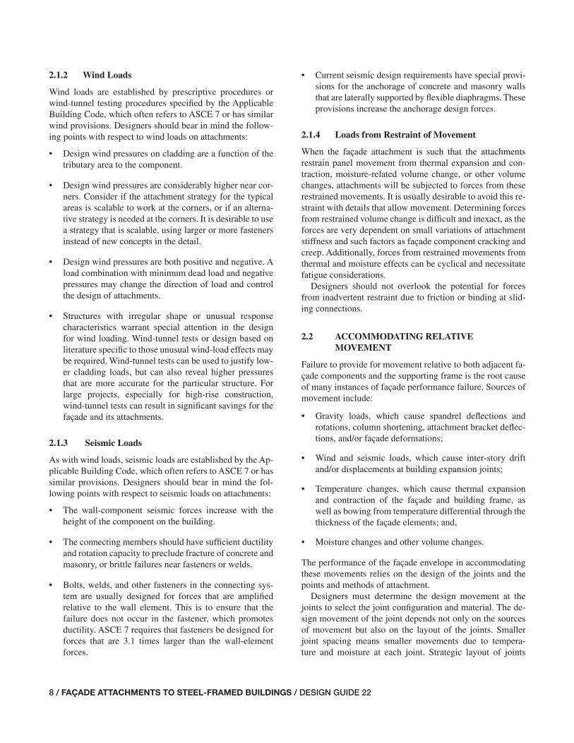
2.1.2 Wind Loads
Wind loads are established by prescriptive procedures or wind-tunnel testing procedures specifi ed by the Applicable Building Code, which often refers to ASCE 7 or has similar wind provisions. Designers should bear in mind the follow-ing points with respect to wind loads on attachments:
• Design wind pressures on cladding are a function of the tributary area to the component.
• Design wind pressures are considerably higher near cor-ners. Consider if the attachment strategy for the typical areas is scalable to work at the corners, or if an alterna-tive strategy is needed at the corners. It is desirable to use a strategy that is scalable, using larger or more fasteners instead of new concepts in the detail.
• Design wind pressures are both positive and negative. A load combination with minimum dead load and negative pressures may change the direction of load and control the design of attachments.
• Structures with irregular shape or unusual response characteristics warrant special attention in the design for wind loading. Wind-tunnel tests or design based on literature specifi c to those unusual wind-load effects may be required. Wind-tunnel tests can be used to justify low-er cladding loads, but can also reveal higher pressures that are more accurate for the particular structure. For large projects, especially for high-rise construction, wind-tunnel tests can result in signifi cant savings for the façade and its attachments.
2.1.3 Seismic Loads
As with wind loads, seismic loads are established by the Ap-plicable Building Code, which often refers to ASCE 7 or has similar provisions. Designers should bear in mind the fol-lowing points with respect to seismic loads on attachments:
• The wall-component seismic forces increase with the height of the component on the building.
• The connecting members should have suffi cient ductility and rotation capacity to preclude fracture of concrete and masonry, or brittle failures near fasteners or welds.
• Bolts, welds, and other fasteners in the connecting sys-tem are usually designed for forces that are amplifi ed relative to the wall element. This is to ensure that the failure does not occur in the fastener, which promotes ductility. ASCE 7 requires that fasteners be designed for forces that are 3.1 times larger than the wall-element forces.
• Current seismic design requirements have special provi-sions for the anchorage of concrete and masonry walls that are laterally supported by fl exible diaphragms. These provisions increase the anchorage design forces.
2.1.4 Loads from Restraint of Movement
When the façade attachment is such that the attachments restrain panel movement from thermal expansion and con-traction, moisture-related volume change, or other volume changes, attachments will be subjected to forces from these restrained movements. It is usually desirable to avoid this re-straint with details that allow movement. Determining forces from restrained volume change is diffi cult and inexact, as the forces are very dependent on small variations of attachment stiffness and such factors as façade component cracking and creep. Additionally, forces from restrained movements from thermal and moisture effects can be cyclical and necessitate fatigue considerations.
Designers should not overlook the potential for forces from inadvertent restraint due to friction or binding at slid-ing connections.
2.2 ACCOMMODATING RELATIVE MOVEMENT
Failure to provide for movement relative to both adjacent fa-çade components and the supporting frame is the root cause of many instances of façade performance failure. Sources of movement include:
• Gravity loads, which cause spandrel defl ections and rotations, column shortening, attachment bracket defl ec-tions, and/or façade deformations;
• Wind and seismic loads, which cause inter-story drift and/or displacements at building expansion joints;
• Temperature changes, which cause thermal expansion and contraction of the façade and building frame, as well as bowing from temperature differential through the thickness of the façade elements; and,
• Moisture changes and other volume changes.
The performance of the façade envelope in accommodating these movements relies on the design of the joints and the points and methods of attachment.
Designers must determine the design movement at the joints to select the joint confi guration and material. The de-sign movement of the joint depends not only on the sources of movement but also on the layout of the joints. Smaller joint spacing means smaller movements due to tempera-ture and moisture at each joint. Strategic layout of joints
005-014_DG22_Ch02.indd 8 7/16/08 4:53:58 PM

DESIGN GUIDE 22 / FAÇADE ATTACHMENTS TO STEEL-FRAMED BUILDINGS / 9
relative to the façade and frame geometry can minimize the effects of the movement at joints due to frame drift. The lay-out of the joints in turn determines the strategy for attachment to the building structure because, for most façade systems, each panel requires independent support and attachment.
Designers have traditionally used rules-of-thumb for fl ex-ural stiffness criteria of spandrel beams. The criteria may limit live-load defl ections to between L/360 and L/600, de-pending on the façade material, to protect the façade ma-terial from cracking. However, controlling joint movement may be a more critical concern.
For example, a w-in. horizontal sealant joint that separates panels supported on a lower fl oor from panels supported on the fl oor above may have an allowable repetitive movement of 4 in. (allowable movement capacity of 333 percent). If project conditions are such that the anticipated thermal and moisture movement is 8 in., this leaves 8 in. for structural movement. Assuming only live loads on the primary struc-ture move the joint subsequent to fi lling it with sealant, the defl ection limit for live loads is then 8 in. Because this is a serviceability check, judgment must be exercised and per-haps the designer decides that using 50 percent of the live load is appropriate. The live load defl ection limit for full live load is then 4 in. This equals L/960 and L/1440 on 20-ft and 30-ft spans, respectively.
Obviously, designers can achieve economies in the steel spandrel girder design if joint layout and sizes are such that they do not control the design. However, extra-wide sealant joints affect the look of the façade, are costly, and have con-struction and performance issues. The design team must bal-ance these issues with the cost of stiffer framing. Figure 2-2 illustrates the effects of spandrel defl ection on panel joints.
Façade attachments must accommodate the relative move-ment between fl oors due to the lateral drift of the frame as a result of wind and seismic forces. ASCE 7 requires that connections and panel joints allow for the story drift caused by seismic displacements, or a minimum of 2 in. The same provisions allow movement to be accommodated by slotted or oversized holes, bending of steel, or other equivalent slid-ing or ductile behavior. Although not explicitly cited in IBC or ASCE 7, similar allowances for drift should be provided for wind forces. Designers should avoid accommodating wind drift by bending of steel parts that result in yielding without evaluation of the potential for low-cycle fatigue.
Inter-story drifts that occur out-of-plane to the façade are accommodated by rotations at the attachments, or by fl ex-ure of the façade, as demonstrated in Figure 2-3. Wind-drift effects on attachments typically are small when the story drift is limited to H/400 or H/500. However, code-permitted seismic drifts may be as high as H/40, or 10 or more times
Fig. 2-2. Effects of spandrel defl ection on panel joints.
005-014_DG22_Ch02.indd 9 7/16/08 4:53:58 PM

10 / FAÇADE ATTACHMENTS TO STEEL-FRAMED BUILDINGS / DESIGN GUIDE 22
these wind limits. Thus, it is important to design the attach-ments to accommodate seismic drifts that cause out-of-plane movement of the wall. Usually, the attachments are designed to allow rotation and/or resist moments induced from the lat-eral displacement and fl exural force in the façade.
Inter-story drift causing movement in the plane of the fa-çade is best accommodated by allowing for slip along a hori-zontal movement joint. Façade panels should have attach-ments that restrain them in-plane at only one fl oor. If panels require attachment to another fl oor for out-of-plane stability, these attachments should allow movement in the plane of the façade. Figure 2-4 illustrates panel layout and its effect on joint movement for in-plane drift.
Corners require special study for joints. Joints designed for in-plane and out-of-plane movements in the fi eld of the wall may not be suffi cient at the corner as in-plane move-ment becomes out-of-plane movement, and vice versa. Figure 2-5 illustrates movements at the corner of a building.
Sometimes façade elements are supported on the founda-tions and the façade elements are self-supporting vertically, using the steel frame only for out-of-plane support (for ex-ample, concrete wall panels). When the façade panels stack more than two tiers, accommodating the in-plane relative seismic drift between the frame and façade elements is dif-fi cult unless the frame is made unusually stiff.
Fig. 2-3. Effects of out-of-plane inter-story drift on façade panels.
The code-prescribed wind and seismic forces are for events with mean recurrence intervals of 50 and 475 years, respec-tively. Attachments must safely accommodate movements, and joints must be designed to prevent hazardous damage to the façades from these levels of forces. However, service-ability checks are normally made with lower-level forces. Designers should select appropriate performance objectives after consultation with the owner.
ASCE 7 suggests in its commentary on serviceability con-siderations that design using the drift at full code-specifi ed wind loads is excessively conservative. ASCE 7 further sug-gests that the appropriate load combination for serviceability checks for short-term effects is:
D + 0.5L + 0.7W
Note that this combination has an annual probability of 5 percent of being exceeded, which translates to 72-percent and 92-percent probabilities of being exceeded in 25 years and 50 years, respectively. Designers and owners should consider these relatively high probabilities that the load case will be exceeded sometime in the life of a building and be sure the consequences of being exceeded are acceptable.
005-014_DG22_Ch02.indd 10 7/16/08 4:53:58 PM

DESIGN GUIDE 22 / FAÇADE ATTACHMENTS TO STEEL-FRAMED BUILDINGS / 11
Fig. 2-4. Effects of panel layout on joint movement for in-plate drift.
Perhaps damage control and functioning sealant joints are acceptable for the 5-percent wind event if the structural as-pects are designed for the load combinations corresponding to a 50-year mean recurrence interval.
Griffi s (1993) addresses serviceability limit states for wind loads on buildings, including the selection of appro-priate drift limits. One point also germane to attachments of façades is that evaluating inter-story drift alone can be misleading. Total inter-story drift is made up of shear and fl exural deformations of the frame. The shear deforma-tions are usually the major source of potential damage to façade systems. Flexural deformations are less of a problem because they result in mostly rigid body motion of the façade elements within the frame panel. This is illustrated in Figure 2-6.
2.3 DURABILITY OF ATTACHMENTS
Façade attachments are usually diffi cult to inspect during the life of a building. To do so may require removal and/or replacement of façade parts, or of the back-up wall, to visu-ally inspect the attachments and their anchors. Furthermore, shortcomings in the façade design and/or construction may lead to water leaks that expose parts within the wall that were
otherwise intended to be dry. Since failure of an attachment could lead to falling hazards, due consideration should be given to durability as a design criterion.
The measures that should be taken to ensure the durabil-ity of attachments to the frame depend upon the water man-agement philosophy of the façade system and the likelihood of the attachments and anchors being exposed to water. Attachments behind a waterproof membrane in a system that employs a drainage layer or cavity are signifi cantly less likely to be exposed to water than attachments for a face-sealed panel system. Designers should also assess the poten-tial for water to pool on the attachment or otherwise expose the attachment to water over a long period of time, even if the leakage is intermittent. Unless there is a high level of confi dence that the attachments will remain dry, corrosion protection should be specifi ed for the attachment parts. Thinner elements, such as light-gauge metal clips, require greater protection than heavier structural steel clips to achieve the same level of durability. If conditions warrant corrosion protection, attachments can be specifi ed as hot-dip galvanized steel or stainless steel.
Hot-dip galvanized steel attachments are usually less ex-pensive, and can be made from plates and shapes that are usually more readily available than similar parts in stainless
005-014_DG22_Ch02.indd 11 7/16/08 4:53:59 PM

12 / FAÇADE ATTACHMENTS TO STEEL-FRAMED BUILDINGS / DESIGN GUIDE 22
Fig. 2-5. Inter-story drift effects at corners.
Fig. 2-6. Inter-story drift effects on façade panels.
005-014_DG22_Ch02.indd 12 7/16/08 4:53:59 PM

DESIGN GUIDE 22 / FAÇADE ATTACHMENTS TO STEEL-FRAMED BUILDINGS / 13
steel. Field welding of galvanized parts also involves more common welding procedures than those for stainless steel parts, provided the proper steps are taken to remove the gal-vanizing at the weld location and then repair with a zinc-rich coating afterward. Care must be taken, however, as corners, edges, or other incidental defects where the zinc coating may be lost can corrode, and the rust product may wash away and stain visible parts of the façade.
Galvanized steel is generally available with specifi ed min-imum yield strengths of 36 ksi and 50 ksi. Stainless steels are available in signifi cantly higher strengths but at higher costs. Also note that the zinc coating of galvanized parts is a sacrifi cial coating with a defi ned service life that depends on the environment in which it is used.
2.4 ACCOUNTING FOR TOLERANCE AND CLEARANCES
One of the most diffi cult design objectives to accomplish is having suffi cient provisions in the details for tolerances and clearances. Tolerances refer to the permissible amount of deviation from a specifi ed criterion (dimension, shape, location, etc.). Clearances refer to space purposely provided between adjacent parts to allow for movement, accommodate tolerances, and provide access, if needed, for installation of attachment hardware.
For the design of façade attachments to steel frames, the suffi cient adjustability and clearance must be provided to al-low the façade to be erected within its tolerances relative to the theoretical plane of the façade. The magnitudes of façade tolerances are usually signifi cantly smaller than the magni-tudes of the tolerances applicable to the fabrication and erec-tion of the steel frame. For example, the exterior line of the
steel frame may be within its tolerances of 1:500 but not more than 1 in. outward and 2 in. inward for a building less than 20 stories, and the tolerance of the curtain wall may be plus or minus 2 in. Therefore, adjustment provided in attachments must account for the steel frame tolerance, and the differences between the tolerances for the steel frame and the façade, for the wall to be erected within its tolerance.
Chapter 4 provides a more detailed discussion of steel frame tolerances and building façade system tolerances.
2.5 CONSTRUCTABILITY AND ECONOMY
Presenting constructability and economy as the last topic in this discussion of design criteria is not meant to minimize its importance. Too often, designers either willingly or inad-vertently sacrifi ce these objectives to mitigate other design concerns. Then, after design and in the midst of construc-tion value engineering or schedule pressures, a subsequent design change may lead to conditions that will promote poor façade performance.
From the beginning of the project design process, design-ers should seek the input of construction experts, steel fab-ricators and erectors, and façade designers, manufacturers, and installers. Appropriate measures for constructability and economy may be highly dependent on such conditions as the project location, market trends, façade materials and sys-tems, and schedule.
While it is true that constructability cannot be achieved without suffi cient adjustability and clearance, the reverse is not true. Fabricators and erectors have seen many examples of details with creative means for adjustment that cannot be built economically. Hence, it is important that constructabil-ity discussions take place early in the design process.
005-014_DG22_Ch02.indd 13 7/16/08 4:54:01 PM

14 / FAÇADE ATTACHMENTS TO STEEL-FRAMED BUILDINGS / DESIGN GUIDE 22
005-014_DG22_Ch02.indd 14 7/16/08 4:54:01 PM
DESIGN GUIDE 22 / FAÇADE ATTACHMENTS TO STEEL-FRAMED BUILDINGS / 15
Chapter 3Overview of Responsibilities for Façade Attachment
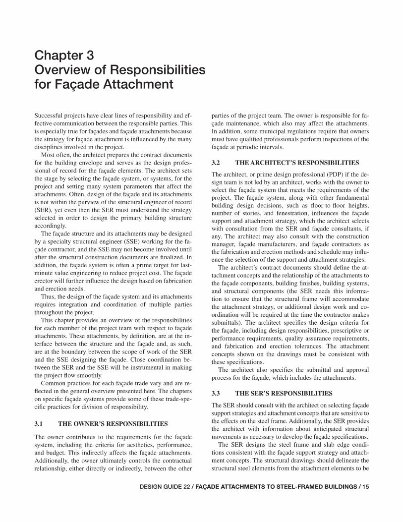
Successful projects have clear lines of responsibility and ef-fective communication between the responsible parties. This is especially true for façades and façade attachments because the strategy for façade attachment is infl uenced by the many disciplines involved in the project.
Most often, the architect prepares the contract documents for the building envelope and serves as the design profes-sional of record for the façade elements. The architect sets the stage by selecting the façade system, or systems, for the project and setting many system parameters that affect the attachments. Often, design of the façade and its attachments is not within the purview of the structural engineer of record (SER), yet even then the SER must understand the strategy selected in order to design the primary building structure accordingly.
The façade structure and its attachments may be designed by a specialty structural engineer (SSE) working for the fa-çade contractor, and the SSE may not become involved until after the structural construction documents are fi nalized. In addition, the façade system is often a prime target for last-minute value engineering to reduce project cost. The façade erector will further infl uence the design based on fabrication and erection needs.
Thus, the design of the façade system and its attachments requires integration and coordination of multiple parties throughout the project.
This chapter provides an overview of the responsibilities for each member of the project team with respect to façade attachments. These attachments, by defi nition, are at the in-terface between the structure and the façade and, as such, are at the boundary between the scope of work of the SER and the SSE designing the façade. Close coordination be-tween the SER and the SSE will be instrumental in making the project fl ow smoothly.
Common practices for each façade trade vary and are re-fl ected in the general overview presented here. The chapters on specifi c façade systems provide some of these trade-spe-cifi c practices for division of responsibility.
3.1 THE OWNER’S RESPONSIBILITIES
The owner contributes to the requirements for the façade system, including the criteria for aesthetics, performance, and budget. This indirectly affects the façade attachments. Additionally, the owner ultimately controls the contractual relationship, either directly or indirectly, between the other
parties of the project team. The owner is responsible for fa-çade maintenance, which also may affect the attachments. In addition, some municipal regulations require that owners must have qualifi ed professionals perform inspections of the façade at periodic intervals.
3.2 THE ARCHITECT’S RESPONSIBILITIES
The architect, or prime design professional (PDP) if the de-sign team is not led by an architect, works with the owner to select the façade system that meets the requirements of the project. The façade system, along with other fundamental building design decisions, such as fl oor-to-fl oor heights, number of stories, and fenestration, infl uences the façade support and attachment strategy, which the architect selects with consultation from the SER and façade consultants, if any. The architect may also consult with the construction manager, façade manufacturers, and façade contractors as the fabrication and erection methods and schedule may infl u-ence the selection of the support and attachment strategies.
The architect’s contract documents should defi ne the at-tachment concepts and the relationship of the attachments to the façade components, building fi nishes, building systems, and structural components (the SER needs this informa-tion to ensure that the structural frame will accommodate the attachment strategy, or additional design work and co-ordination will be required at the time the contractor makes submittals). The architect specifi es the design criteria for the façade, including design responsibilities, prescriptive or performance requirements, quality assurance requirements, and fabrication and erection tolerances. The attachment concepts shown on the drawings must be consistent with these specifi cations.
The architect also specifi es the submittal and approval process for the façade, which includes the attachments.
3.3 THE SER’S RESPONSIBILITIES
The SER should consult with the architect on selecting façade support strategies and attachment concepts that are sensitive to the effects on the steel frame. Additionally, the SER provides the architect with information about anticipated structural movements as necessary to develop the façade specifi cations.
The SER designs the steel frame and slab edge condi-tions consistent with the façade support strategy and attach-ment concepts. The structural drawings should delineate the structural steel elements from the attachment elements to be
015-016_DG22_Ch03.indd 15 7/16/08 4:55:48 PM

16 / FAÇADE ATTACHMENTS TO STEEL-FRAMED BUILDINGS / DESIGN GUIDE 22
designed by the SSE. The structural drawings should also show the assumptions and limitations of the locations and magnitudes of the façade attachment loads.
The SER should show the fabrication and erection toler-ances for the structural steel on the structural drawings and specifi cations. The structural steel details and concepts must account for suffi cient fi eld adjustment to accommodate the difference between the tolerances of the steel frame and the specifi ed acceptable tolerance for the fi nal façade position.
The SER reviews submittals by the SSE and the façade contractor specifi cally for the effect of the façade and its at-tachments on the primary building structure. The SER en-sures that the design of the attachments is consistent with the loads associated with the support strategy and attachment concepts the SER used to design the steel framing.
The SER may or may not contract to assist the architect with development of portions of the façade design criteria, such as loads. If part of the SER’s scope of services with the architect, the SER reviews the façade submittals for confor-mance with the structural design criteria for the façade.
3.4 THE SSE’S RESPONSIBILITIES
The SSE is the design professional responsible for the design of the façade and/or its attachments to the structural frame. The SSE for the attachments is usually under contract with the façade contractor. This is almost always the case if the SSE for the attachments is also the SSE for the design of the façade itself, as is often the case with precast suppliers, for example.
The SSE designs the attachments in accordance with the project specifi cations and consistent with the concepts and
limitations presented in the design documents. This includes providing attachments with suffi cient adjustability and clear-ance to meet the project requirements. The SSE prepares cal-culations and drawings for submittal in accordance with the project specifi cations. The SSE is responsible for the design of the attachments, including ensuring proper quality assur-ance for the installation in accordance with the requirements in the Applicable Building Code and project specifi cations.
When the Applicable Building Code requires special in-spection, the SSE is responsible for inspecting the attach-ments as delegated by the SER.
3.5 THE GENERAL CONTRACTOR’S AND CONSTRUCTION MANAGER’S RESPONSIBILITIES
The general contractor coordinates the trades involved with the façade and its attachments. This usually includes the trades for the structural steel, concrete slab, and façade system(s). The general contractor coordinates the submittals of the various subcontractors and reviews them for coordina-tion and conformance with the project specifi cations. The general contractor also ensures inspectors for the façade attachments have timely access to the work.
3.6 THE FAÇADE CONTRACTOR’S RESPONSIBILITIES
In addition to fabrication and erection of the façade, the fa-çade contractor is often required by project specifi cations to be responsible for the structural design of the façade and its attachment. The SSE usually will be employed by either the general contractor or the façade contractor.
015-016_DG22_Ch03.indd 16 7/16/08 4:55:48 PM
DESIGN GUIDE 22 / FAÇADE ATTACHMENTS TO STEEL-FRAMED BUILDINGS / 17
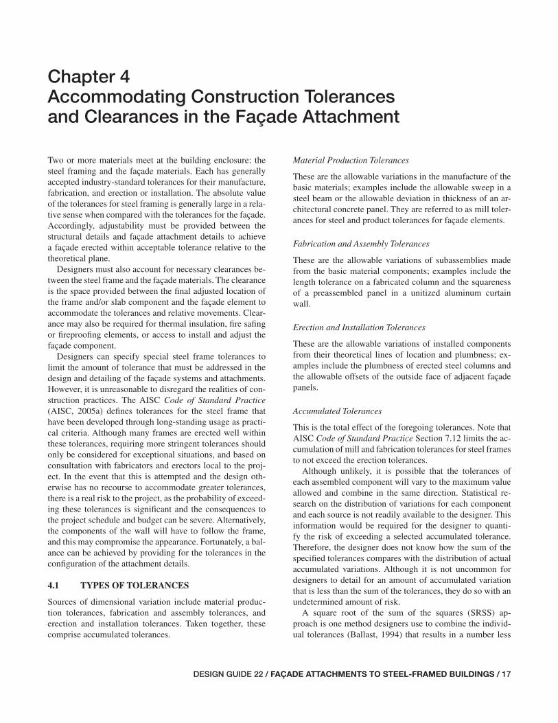
Chapter 4 Accommodating Construction Tolerances and Clearances in the Façade Attachment
Two or more materials meet at the building enclosure: the steel framing and the façade materials. Each has generally accepted industry-standard tolerances for their manufacture, fabrication, and erection or installation. The absolute value of the tolerances for steel framing is generally large in a rela-tive sense when compared with the tolerances for the façade. Accordingly, adjustability must be provided between the structural details and façade attachment details to achieve a façade erected within acceptable tolerance relative to the theoretical plane.
Designers must also account for necessary clearances be-tween the steel frame and the façade materials. The clearance is the space provided between the fi nal adjusted location of the frame and/or slab component and the façade element to accommodate the tolerances and relative movements. Clear-ance may also be required for thermal insulation, fi re safi ng or fi reproofi ng elements, or access to install and adjust the façade component.
Designers can specify special steel frame tolerances to limit the amount of tolerance that must be addressed in the design and detailing of the façade systems and attachments. However, it is unreasonable to disregard the realities of con-struction practices. The AISC Code of Standard Practice (AISC, 2005a) defi nes tolerances for the steel frame that have been developed through long-standing usage as practi-cal criteria. Although many frames are erected well within these tolerances, requiring more stringent tolerances should only be considered for exceptional situations, and based on consultation with fabricators and erectors local to the proj-ect. In the event that this is attempted and the design oth-erwise has no recourse to accommodate greater tolerances, there is a real risk to the project, as the probability of exceed-ing these tolerances is signifi cant and the consequences to the project schedule and budget can be severe. Alternatively, the components of the wall will have to follow the frame, and this may compromise the appearance. Fortunately, a bal-ance can be achieved by providing for the tolerances in the confi guration of the attachment details.
4.1 TYPES OF TOLERANCES
Sources of dimensional variation include material produc-tion tolerances, fabrication and assembly tolerances, and erection and installation tolerances. Taken together, these comprise accumulated tolerances.
Material Production Tolerances
These are the allowable variations in the manufacture of the basic materials; examples include the allowable sweep in a steel beam or the allowable deviation in thickness of an ar-chitectural concrete panel. They are referred to as mill toler-ances for steel and product tolerances for façade elements.
Fabrication and Assembly Tolerances
These are the allowable variations of subassemblies made from the basic material components; examples include the length tolerance on a fabricated column and the squareness of a preassembled panel in a unitized aluminum curtain wall.
Erection and Installation Tolerances
These are the allowable variations of installed components from their theoretical lines of location and plumbness; ex-amples include the plumbness of erected steel columns and the allowable offsets of the outside face of adjacent façade panels.
Accumulated Tolerances
This is the total effect of the foregoing tolerances. Note that AISC Code of Standard Practice Section 7.12 limits the ac-cumulation of mill and fabrication tolerances for steel frames to not exceed the erection tolerances.
Although unlikely, it is possible that the tolerances of each assembled component will vary to the maximum value allowed and combine in the same direction. Statistical re-search on the distribution of variations for each component and each source is not readily available to the designer. This information would be required for the designer to quanti-fy the risk of exceeding a selected accumulated tolerance. Therefore, the designer does not know how the sum of the specifi ed tolerances compares with the distribution of actual accumulated variations. Although it is not uncommon for designers to detail for an amount of accumulated variation that is less than the sum of the tolerances, they do so with an undetermined amount of risk.
A square root of the sum of the squares (SRSS) ap-proach is one method designers use to combine the individ-ual tolerances (Ballast, 1994) that results in a number less
017-030_DG22_Ch04.indd 17 7/16/08 4:55:09 PM

18 / FAÇADE ATTACHMENTS TO STEEL-FRAMED BUILDINGS / DESIGN GUIDE 22
Cumulative Tolerances
Of most interest to the designer on the subject of façade at-tachments is the necessary design adjustment for the total cumulative tolerance of the exterior frame. In particular, the adjustment must accommodate the allowable variation, inward or outward, of the frame line from the theoretical plumb column line at any fl oor elevation. Section 7.12 in the AISC Code of Standard Practice limits the accumulation of mill and fabrication tolerances for steel frames.
Tolerances for column base location, exterior column plumbness, and beam sweep are the most signifi cant compo-nents of the cumulative tolerance relative to façade systems. Exterior column plumbness depends on the height above the base and the number of stories. The allowable spandrel beam sweep depends on the beam fl ange width and the beam length. Tables 4-1 through 4-6 provide the inward and out-ward (horizontal) tolerance at each fl oor for buildings up to 50 stories with combinations of 10-ft, 12-ft, and 14-ft story heights and 30-ft and 40-ft spandrel spans.
(sometimes signifi cantly less) than the absolute sum. There is no basis in statistical theory for this. For the case of fa-çades supported on steel frames, the absolute value of tol-erance of the steel frame is large compared with material, fabrication, and erection tolerances of the other components. This dominates the total for which designers must account. Thus, using an SRSS approach essentially means designers are optimistically assuming that the required adjustability to account for accumulated tolerance will not be much greater than that needed for the frame alone.
Designers must use judgment and understand the conse-quences when selecting an attachment strategy that cannot accommodate the accumulated tolerances based on the sum of the maximums for the individual components. Given the difference in magnitude between the tolerances for frame erection relative to tolerances for other components, design-ers should, as a minimum, account for the entire frame erec-tion tolerance and use judgment for what additional amount is warranted. Alternatively, designers can consider the effect on the appearance and performance of the wall if it were to follow the as-built line of the steel frame. This is often the necessary approach for tall buildings.
4.2 STRUCTURAL STEEL TOLERANCES
Structural steel tolerances are composed of mill, fabrication, and erection tolerances. Provisions for adjustability will also be discussed.
Mill Tolerances
Designers should recognize the variations in cross-sectional geometry of wide-fl ange and other shapes. Figure 4-1 shows the mill tolerances on the cross-section of a W-shape. ASTM A6/A6M sets forth allowable variations in cross-section, as well as such length-based tolerances such as camber and sweep. For fl ange widths less than 6 in., camber variation (in.) is limited to the member length, L (ft), divided by 80. Sweep variation (in.) is limited to L/40. For fl ange widths equal to or greater than 6 in., the camber and sweep variations (in.) are both limited to L/80. Permitted variations of camber and sweep in column sections are specifi ed according to length and section size. A convenient summary of tolerances for structural shapes based upon ASTM requirements is pro-vided in Tables 1-22 through 1-29 in the AISC Manual.
Fabrication Tolerances
Section 6.4 in the AISC Code of Standard Practice defi nes the fabrication tolerances for the steel frame.
Erection Tolerances
Section 7.13 in the AISC Code of Standard Practice de-fi nes the erection tolerances for the steel frame. Figures 4-2 through 4-6 illustrate many of these tolerances.
Fig. 4-1. Mill tolerances on the cross-section of W-shape (AISC, 2005a).
017-030_DG22_Ch04.indd 18 7/17/08 3:07:00 PM

DESIGN GUIDE 22 / FAÇADE ATTACHMENTS TO STEEL-FRAMED BUILDINGS / 19
Table 4-1. Horizontal Tolerances for Steel Frames 10-ft Story Height and 30-ft Spandrel Span
StoryΔcsp, in. Δcpt, in. Δbsw, in. Δtot, in.
� � � � � � � �
foundation 0.25 0.25 – – – – – –1 – – 0.49 0.49 0.38 0.38 0.87 0.872 – – 0.73 0.73 0.38 0.38 1.11 1.113 – – 0.97 0.97 0.38 0.38 1.35 1.354 – – 1.21 1.00 0.38 0.38 1.59 1.385 – – 1.45 1.00 0.38 0.38 1.83 1.386 – – 1.69 1.00 0.38 0.38 2.07 1.387 – – 1.93 1.00 0.38 0.38 2.31 1.388 – – 2.00 1.00 0.38 0.38 2.38 1.389 – – 2.00 1.00 0.38 0.38 2.38 1.3810 – – 2.00 1.00 0.38 0.38 2.38 1.3811 – – 2.00 1.00 0.38 0.38 2.38 1.3812 – – 2.00 1.00 0.38 0.38 2.38 1.3813 – – 2.00 1.00 0.38 0.38 2.38 1.3814 – – 2.00 1.00 0.38 0.38 2.38 1.3815 – – 2.00 1.00 0.38 0.38 2.38 1.3816 – – 2.00 1.00 0.38 0.38 2.38 1.3817 – – 2.00 1.00 0.38 0.38 2.38 1.3818 – – 2.00 1.00 0.38 0.38 2.38 1.3819 – – 2.00 1.00 0.38 0.38 2.38 1.3820 – – 2.00 1.00 0.38 0.38 2.38 1.3821 – – 2.06 1.06 0.38 0.38 2.44 1.4422 – – 2.13 1.13 0.38 0.38 2.50 1.5023 – – 2.19 1.19 0.38 0.38 2.56 1.5624 – – 2.25 1.25 0.38 0.38 2.63 1.6325 – – 2.31 1.31 0.38 0.38 2.69 1.6926 – – 2.38 1.38 0.38 0.38 2.75 1.7527 – – 2.44 1.44 0.38 0.38 2.81 1.8128 – – 2.50 1.50 0.38 0.38 2.88 1.8829 – – 2.56 1.56 0.38 0.38 2.94 1.9430 – – 2.63 1.63 0.38 0.38 3.00 2.0031 – – 2.69 1.69 0.38 0.38 3.06 2.0632 – – 2.75 1.75 0.38 0.38 3.13 2.1333 – – 2.81 1.81 0.38 0.38 3.19 2.1934 – – 2.88 1.88 0.38 0.38 3.25 2.2535 – – 2.94 1.94 0.38 0.38 3.31 2.3136 – – 3.00 2.00 0.38 0.38 3.38 2.3837 – – 3.00 2.00 0.38 0.38 3.38 2.3838 – – 3.00 2.00 0.38 0.38 3.38 2.3839 – – 3.00 2.00 0.38 0.38 3.38 2.3840 – – 3.00 2.00 0.38 0.38 3.38 2.3841 – – 3.00 2.00 0.38 0.38 3.38 2.3842 – – 3.00 2.00 0.38 0.38 3.38 2.3843 – – 3.00 2.00 0.38 0.38 3.38 2.3844 – – 3.00 2.00 0.38 0.38 3.38 2.3845 – – 3.00 2.00 0.38 0.38 3.38 2.3846 – – 3.00 2.00 0.38 0.38 3.38 2.3847 – – 3.00 2.00 0.38 0.38 3.38 2.3848 – – 3.00 2.00 0.38 0.38 3.38 2.3849 – – 3.00 2.00 0.38 0.38 3.38 2.3850 – – 3.00 2.00 0.38 0.38 3.38 2.38
Notes:1. Δcsp = column base location tolerance 4. Δtot(+) = Δcpt(+) + Δbsw(+)2. Δcpt = column plumbness tolerance (includes Δcsp) 5. Δtot(−) = Δcpt(−) + Δbsw(−)3. Δbsw = beam/edge plate sweep tolerance 6. (+) = toward building line (−) = away from building line
017-030_DG22_Ch04.indd 19 7/16/08 4:55:10 PM
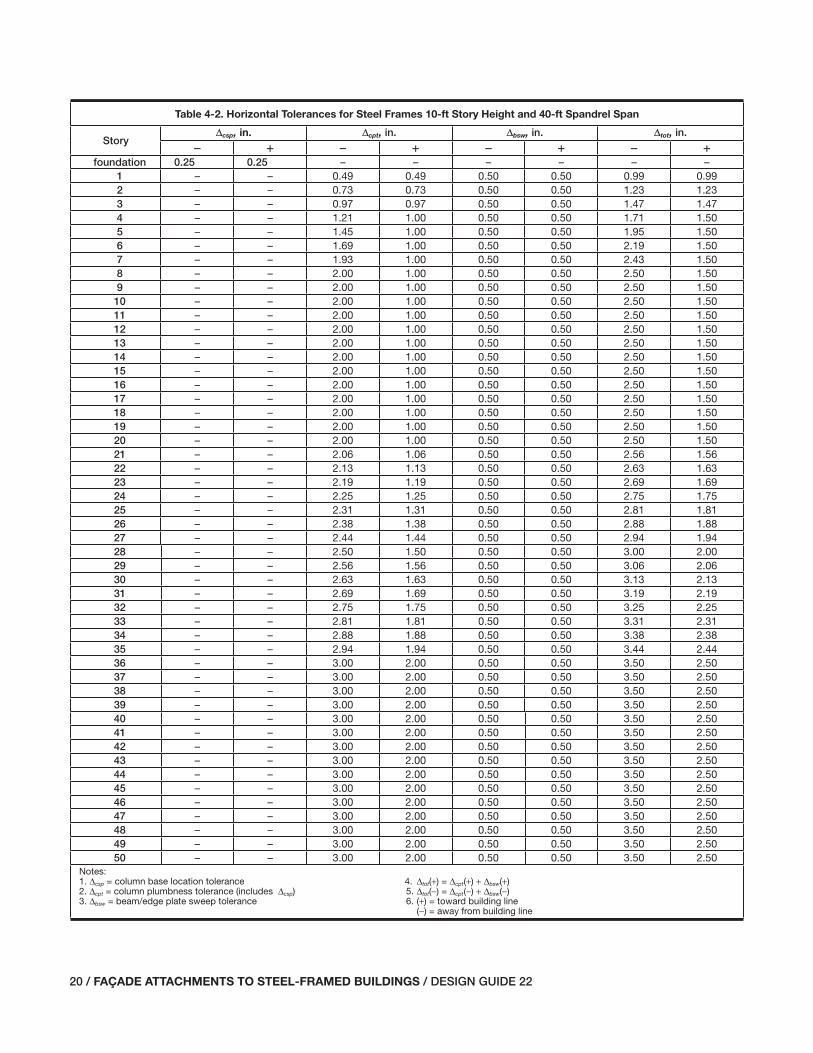
20 / FAÇADE ATTACHMENTS TO STEEL-FRAMED BUILDINGS / DESIGN GUIDE 22
Table 4-2. Horizontal Tolerances for Steel Frames 10-ft Story Height and 40-ft Spandrel Span
StoryΔcsp, in. Δcpt, in. Δbsw, in. Δtot, in.
� � � � � � � �
foundation 0.25 0.25 – – – – – –1 – – 0.49 0.49 0.50 0.50 0.99 0.992 – – 0.73 0.73 0.50 0.50 1.23 1.233 – – 0.97 0.97 0.50 0.50 1.47 1.474 – – 1.21 1.00 0.50 0.50 1.71 1.505 – – 1.45 1.00 0.50 0.50 1.95 1.506 – – 1.69 1.00 0.50 0.50 2.19 1.507 – – 1.93 1.00 0.50 0.50 2.43 1.508 – – 2.00 1.00 0.50 0.50 2.50 1.509 – – 2.00 1.00 0.50 0.50 2.50 1.5010 – – 2.00 1.00 0.50 0.50 2.50 1.5011 – – 2.00 1.00 0.50 0.50 2.50 1.5012 – – 2.00 1.00 0.50 0.50 2.50 1.5013 – – 2.00 1.00 0.50 0.50 2.50 1.5014 – – 2.00 1.00 0.50 0.50 2.50 1.5015 – – 2.00 1.00 0.50 0.50 2.50 1.5016 – – 2.00 1.00 0.50 0.50 2.50 1.5017 – – 2.00 1.00 0.50 0.50 2.50 1.5018 – – 2.00 1.00 0.50 0.50 2.50 1.5019 – – 2.00 1.00 0.50 0.50 2.50 1.5020 – – 2.00 1.00 0.50 0.50 2.50 1.5021 – – 2.06 1.06 0.50 0.50 2.56 1.5622 – – 2.13 1.13 0.50 0.50 2.63 1.6323 – – 2.19 1.19 0.50 0.50 2.69 1.6924 – – 2.25 1.25 0.50 0.50 2.75 1.7525 – – 2.31 1.31 0.50 0.50 2.81 1.8126 – – 2.38 1.38 0.50 0.50 2.88 1.8827 – – 2.44 1.44 0.50 0.50 2.94 1.9428 – – 2.50 1.50 0.50 0.50 3.00 2.0029 – – 2.56 1.56 0.50 0.50 3.06 2.0630 – – 2.63 1.63 0.50 0.50 3.13 2.1331 – – 2.69 1.69 0.50 0.50 3.19 2.1932 – – 2.75 1.75 0.50 0.50 3.25 2.2533 – – 2.81 1.81 0.50 0.50 3.31 2.3134 – – 2.88 1.88 0.50 0.50 3.38 2.3835 – – 2.94 1.94 0.50 0.50 3.44 2.4436 – – 3.00 2.00 0.50 0.50 3.50 2.5037 – – 3.00 2.00 0.50 0.50 3.50 2.5038 – – 3.00 2.00 0.50 0.50 3.50 2.5039 – – 3.00 2.00 0.50 0.50 3.50 2.5040 – – 3.00 2.00 0.50 0.50 3.50 2.5041 – – 3.00 2.00 0.50 0.50 3.50 2.5042 – – 3.00 2.00 0.50 0.50 3.50 2.5043 – – 3.00 2.00 0.50 0.50 3.50 2.5044 – – 3.00 2.00 0.50 0.50 3.50 2.5045 – – 3.00 2.00 0.50 0.50 3.50 2.5046 – – 3.00 2.00 0.50 0.50 3.50 2.5047 – – 3.00 2.00 0.50 0.50 3.50 2.5048 – – 3.00 2.00 0.50 0.50 3.50 2.5049 – – 3.00 2.00 0.50 0.50 3.50 2.5050 – – 3.00 2.00 0.50 0.50 3.50 2.50
Notes:1. Δcsp = column base location tolerance 4. Δtot(+) = Δcpt(+) + Δbsw(+)2. Δcpt = column plumbness tolerance (includes Δcsp) 5. Δtot(−) = Δcpt(−) + Δbsw(−)3. Δbsw = beam/edge plate sweep tolerance 6. (+) = toward building line (−) = away from building line
017-030_DG22_Ch04.indd 20 7/16/08 4:55:10 PM

DESIGN GUIDE 22 / FAÇADE ATTACHMENTS TO STEEL-FRAMED BUILDINGS / 21
Table 4-3. Horizontal Tolerances for Steel Frames 12-ft Story Height and 30-ft Spandrel Span
StoryΔcsp, in. Δcpt, in. Δbsw, in. Δtot, in.
� � � � � � � �
foundation 0.25 0.25 – – – – – –1 – – 0.54 0.54 0.38 0.38 0.91 0.912 – – 0.83 0.83 0.38 0.38 1.20 1.203 – – 1.11 1.00 0.38 0.38 1.49 1.384 – – 1.40 1.00 0.38 0.38 1.78 1.385 – – 1.69 1.00 0.38 0.38 2.07 1.386 – – 1.98 1.00 0.38 0.38 2.35 1.387 – – 2.00 1.00 0.38 0.38 2.38 1.388 – – 2.00 1.00 0.38 0.38 2.38 1.389 – – 2.00 1.00 0.38 0.38 2.38 1.3810 – – 2.00 1.00 0.38 0.38 2.38 1.3811 – – 2.00 1.00 0.38 0.38 2.38 1.3812 – – 2.00 1.00 0.38 0.38 2.38 1.3813 – – 2.00 1.00 0.38 0.38 2.38 1.3814 – – 2.00 1.00 0.38 0.38 2.38 1.3815 – – 2.00 1.00 0.38 0.38 2.38 1.3816 – – 2.00 1.00 0.38 0.38 2.38 1.3817 – – 2.00 1.00 0.38 0.38 2.38 1.3818 – – 2.00 1.00 0.38 0.38 2.38 1.3819 – – 2.00 1.00 0.38 0.38 2.38 1.3820 – – 2.00 1.00 0.38 0.38 2.38 1.3821 – – 2.06 1.06 0.38 0.38 2.44 1.4422 – – 2.13 1.13 0.38 0.38 2.50 1.5023 – – 2.19 1.19 0.38 0.38 2.56 1.5624 – – 2.25 1.25 0.38 0.38 2.63 1.6325 – – 2.31 1.31 0.38 0.38 2.69 1.6926 – – 2.38 1.38 0.38 0.38 2.75 1.7527 – – 2.44 1.44 0.38 0.38 2.81 1.8128 – – 2.50 1.50 0.38 0.38 2.88 1.8829 – – 2.56 1.56 0.38 0.38 2.94 1.9430 – – 2.63 1.63 0.38 0.38 3.00 2.0031 – – 2.69 1.69 0.38 0.38 3.06 2.0632 – – 2.75 1.75 0.38 0.38 3.13 2.1333 – – 2.81 1.81 0.38 0.38 3.19 2.1934 – – 2.88 1.88 0.38 0.38 3.25 2.2535 – – 2.94 1.94 0.38 0.38 3.31 2.3136 – – 3.00 2.00 0.38 0.38 3.38 2.3837 – – 3.00 2.00 0.38 0.38 3.38 2.3838 – – 3.00 2.00 0.38 0.38 3.38 2.3839 – – 3.00 2.00 0.38 0.38 3.38 2.3840 – – 3.00 2.00 0.38 0.38 3.38 2.3841 – – 3.00 2.00 0.38 0.38 3.38 2.3842 – – 3.00 2.00 0.38 0.38 3.38 2.3843 – – 3.00 2.00 0.38 0.38 3.38 2.3844 – – 3.00 2.00 0.38 0.38 3.38 2.3845 – – 3.00 2.00 0.38 0.38 3.38 2.3846 – – 3.00 2.00 0.38 0.38 3.38 2.3847 – – 3.00 2.00 0.38 0.38 3.38 2.3848 – – 3.00 2.00 0.38 0.38 3.38 2.3849 – – 3.00 2.00 0.38 0.38 3.38 2.3850 – – 3.00 2.00 0.38 0.38 3.38 2.38
Notes:1. Δcsp = column base location tolerance 4. Δtot(+) = Δcpt(+) + Δbsw(+)2. Δcpt = column plumbness tolerance (includes Δcsp) 5. Δtot(−) = Δcpt(−) + Δbsw(−)3. Δbsw = beam/edge plate sweep tolerance 6. (+) = toward building line (−) = away from building line
017-030_DG22_Ch04.indd 21 7/16/08 4:55:10 PM

22 / FAÇADE ATTACHMENTS TO STEEL-FRAMED BUILDINGS / DESIGN GUIDE 22
Table 4-4. Horizontal Tolerances for Steel Frames 12-ft Story Height and 40-ft Spandrel Span
StoryΔcsp, in. Δcpt, in. Δbsw, in. Δtot, in.
� � � � � � � �
foundation 0.25 0.25 – – – – – –1 – – 0.54 0.54 0.50 0.50 1.04 1.042 – – 0.83 0.83 0.50 0.50 1.33 1.333 – – 1.11 1.00 0.50 0.50 1.61 1.504 – – 1.40 1.00 0.50 0.50 1.90 1.505 – – 1.69 1.00 0.50 0.50 2.19 1.506 – – 1.98 1.00 0.50 0.50 2.48 1.507 – – 2.00 1.00 0.50 0.50 2.50 1.508 – – 2.00 1.00 0.50 0.50 2.50 1.509 – – 2.00 1.00 0.50 0.50 2.50 1.5010 – – 2.00 1.00 0.50 0.50 2.50 1.5011 – – 2.00 1.00 0.50 0.50 2.50 1.5012 – – 2.00 1.00 0.50 0.50 2.50 1.5013 – – 2.00 1.00 0.50 0.50 2.50 1.5014 – – 2.00 1.00 0.50 0.50 2.50 1.5015 – – 2.00 1.00 0.50 0.50 2.50 1.5016 – – 2.00 1.00 0.50 0.50 2.50 1.5017 – – 2.00 1.00 0.50 0.50 2.50 1.5018 – – 2.00 1.00 0.50 0.50 2.50 1.5019 – – 2.00 1.00 0.50 0.50 2.50 1.5020 – – 2.00 1.00 0.50 0.50 2.50 1.5021 – – 2.06 1.06 0.50 0.50 2.56 1.5622 – – 2.13 1.13 0.50 0.50 2.63 1.6323 – – 2.19 1.19 0.50 0.50 2.69 1.6924 – – 2.25 1.25 0.50 0.50 2.75 1.7525 – – 2.31 1.31 0.50 0.50 2.81 1.8126 – – 2.38 1.38 0.50 0.50 2.88 1.8827 – – 2.44 1.44 0.50 0.50 2.94 1.9428 – – 2.50 1.50 0.50 0.50 3.00 2.0029 – – 2.56 1.56 0.50 0.50 3.06 2.0630 – – 2.63 1.63 0.50 0.50 3.13 2.1331 – – 2.69 1.69 0.50 0.50 3.19 2.1932 – – 2.75 1.75 0.50 0.50 3.25 2.2533 – – 2.81 1.81 0.50 0.50 3.31 2.3134 – – 2.88 1.88 0.50 0.50 3.38 2.3835 – – 2.94 1.94 0.50 0.50 3.44 2.4436 – – 3.00 2.00 0.50 0.50 3.50 2.5037 – – 3.00 2.00 0.50 0.50 3.50 2.5038 – – 3.00 2.00 0.50 0.50 3.50 2.5039 – – 3.00 2.00 0.50 0.50 3.50 2.5040 – – 3.00 2.00 0.50 0.50 3.50 2.5041 – – 3.00 2.00 0.50 0.50 3.50 2.5042 – – 3.00 2.00 0.50 0.50 3.50 2.5043 – – 3.00 2.00 0.50 0.50 3.50 2.5044 – – 3.00 2.00 0.50 0.50 3.50 2.5045 – – 3.00 2.00 0.50 0.50 3.50 2.5046 – – 3.00 2.00 0.50 0.50 3.50 2.5047 – – 3.00 2.00 0.50 0.50 3.50 2.5048 – – 3.00 2.00 0.50 0.50 3.50 2.5049 – – 3.00 2.00 0.50 0.50 3.50 2.5050 – – 3.00 2.00 0.50 0.50 3.50 2.50
Notes:1. Δcsp = column base location tolerance 4. Δtot(+) = Δcpt(+) + Δbsw(+)2. Δcpt = column plumbness tolerance (includes Δcsp) 5. Δtot(−) = Δcpt(−) + Δbsw(−)3. Δbsw = beam/edge plate sweep tolerance 6. (+) = toward building line (−) = away from building line
017-030_DG22_Ch04.indd 22 7/16/08 4:55:10 PM
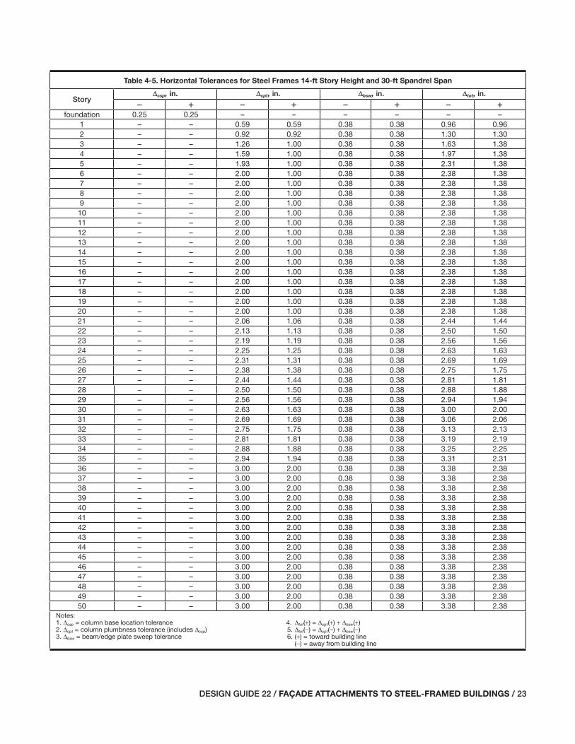
DESIGN GUIDE 22 / FAÇADE ATTACHMENTS TO STEEL-FRAMED BUILDINGS / 23
Table 4-5. Horizontal Tolerances for Steel Frames 14-ft Story Height and 30-ft Spandrel Span
StoryΔcsp, in. Δcpt, in. Δbsw, in. Δtot, in.
� � � � � � � �
foundation 0.25 0.25 – – – – – –1 – – 0.59 0.59 0.38 0.38 0.96 0.962 – – 0.92 0.92 0.38 0.38 1.30 1.303 – – 1.26 1.00 0.38 0.38 1.63 1.384 – – 1.59 1.00 0.38 0.38 1.97 1.385 – – 1.93 1.00 0.38 0.38 2.31 1.386 – – 2.00 1.00 0.38 0.38 2.38 1.387 – – 2.00 1.00 0.38 0.38 2.38 1.388 – – 2.00 1.00 0.38 0.38 2.38 1.389 – – 2.00 1.00 0.38 0.38 2.38 1.3810 – – 2.00 1.00 0.38 0.38 2.38 1.3811 – – 2.00 1.00 0.38 0.38 2.38 1.3812 – – 2.00 1.00 0.38 0.38 2.38 1.3813 – – 2.00 1.00 0.38 0.38 2.38 1.3814 – – 2.00 1.00 0.38 0.38 2.38 1.3815 – – 2.00 1.00 0.38 0.38 2.38 1.3816 – – 2.00 1.00 0.38 0.38 2.38 1.3817 – – 2.00 1.00 0.38 0.38 2.38 1.3818 – – 2.00 1.00 0.38 0.38 2.38 1.3819 – – 2.00 1.00 0.38 0.38 2.38 1.3820 – – 2.00 1.00 0.38 0.38 2.38 1.3821 – – 2.06 1.06 0.38 0.38 2.44 1.4422 – – 2.13 1.13 0.38 0.38 2.50 1.5023 – – 2.19 1.19 0.38 0.38 2.56 1.5624 – – 2.25 1.25 0.38 0.38 2.63 1.6325 – – 2.31 1.31 0.38 0.38 2.69 1.6926 – – 2.38 1.38 0.38 0.38 2.75 1.7527 – – 2.44 1.44 0.38 0.38 2.81 1.8128 – – 2.50 1.50 0.38 0.38 2.88 1.8829 – – 2.56 1.56 0.38 0.38 2.94 1.9430 – – 2.63 1.63 0.38 0.38 3.00 2.0031 – – 2.69 1.69 0.38 0.38 3.06 2.0632 – – 2.75 1.75 0.38 0.38 3.13 2.1333 – – 2.81 1.81 0.38 0.38 3.19 2.1934 – – 2.88 1.88 0.38 0.38 3.25 2.2535 – – 2.94 1.94 0.38 0.38 3.31 2.3136 – – 3.00 2.00 0.38 0.38 3.38 2.3837 – – 3.00 2.00 0.38 0.38 3.38 2.3838 – – 3.00 2.00 0.38 0.38 3.38 2.3839 – – 3.00 2.00 0.38 0.38 3.38 2.3840 – – 3.00 2.00 0.38 0.38 3.38 2.3841 – – 3.00 2.00 0.38 0.38 3.38 2.3842 – – 3.00 2.00 0.38 0.38 3.38 2.3843 – – 3.00 2.00 0.38 0.38 3.38 2.3844 – – 3.00 2.00 0.38 0.38 3.38 2.3845 – – 3.00 2.00 0.38 0.38 3.38 2.3846 – – 3.00 2.00 0.38 0.38 3.38 2.3847 – – 3.00 2.00 0.38 0.38 3.38 2.3848 – – 3.00 2.00 0.38 0.38 3.38 2.3849 – – 3.00 2.00 0.38 0.38 3.38 2.3850 – – 3.00 2.00 0.38 0.38 3.38 2.38
Notes:1. Δcsp = column base location tolerance 4. Δtot(+) = Δcpt(+) + Δbsw(+)2. Δcpt = column plumbness tolerance (includes Δcsp) 5. Δtot(−) = Δcpt(−) + Δbsw(−)3. Δbsw = beam/edge plate sweep tolerance 6. (+) = toward building line (−) = away from building line
017-030_DG22_Ch04.indd 23 7/16/08 4:55:10 PM

24 / FAÇADE ATTACHMENTS TO STEEL-FRAMED BUILDINGS / DESIGN GUIDE 22
Table 4-6. Horizontal Tolerances for Steel Frames 14-ft Story Height and 40-ft Spandrel Span
StoryΔcsp, in. Δcpt, in. Δbsw, in. Δtot, in.
� � � � � � � �
foundation 0.25 0.25 – – – – – –1 – – 0.59 0.59 0.50 0.50 1.09 1.092 – – 0.92 0.92 0.50 0.50 1.42 1.423 – – 1.26 1.00 0.50 0.50 1.76 1.504 – – 1.59 1.00 0.50 0.50 2.09 1.505 – – 1.93 1.00 0.50 0.50 2.43 1.506 – – 2.00 1.00 0.50 0.50 2.50 1.507 – – 2.00 1.00 0.50 0.50 2.50 1.508 – – 2.00 1.00 0.50 0.50 2.50 1.509 – – 2.00 1.00 0.50 0.50 2.50 1.5010 – – 2.00 1.00 0.50 0.50 2.50 1.5011 – – 2.00 1.00 0.50 0.50 2.50 1.5012 – – 2.00 1.00 0.50 0.50 2.50 1.5013 – – 2.00 1.00 0.50 0.50 2.50 1.5014 – – 2.00 1.00 0.50 0.50 2.50 1.5015 – – 2.00 1.00 0.50 0.50 2.50 1.5016 – – 2.00 1.00 0.50 0.50 2.50 1.5017 – – 2.00 1.00 0.50 0.50 2.50 1.5018 – – 2.00 1.00 0.50 0.50 2.50 1.5019 – – 2.00 1.00 0.50 0.50 2.50 1.5020 – – 2.00 1.00 0.50 0.50 2.50 1.5021 – – 2.06 1.06 0.50 0.50 2.56 1.5622 – – 2.13 1.13 0.50 0.50 2.63 1.6323 – – 2.19 1.19 0.50 0.50 2.69 1.6924 – – 2.25 1.25 0.50 0.50 2.75 1.7525 – – 2.31 1.31 0.50 0.50 2.81 1.8126 – – 2.38 1.38 0.50 0.50 2.88 1.8827 – – 2.44 1.44 0.50 0.50 2.94 1.9428 – – 2.50 1.50 0.50 0.50 3.00 2.0029 – – 2.56 1.56 0.50 0.50 3.06 2.0630 – – 2.63 1.63 0.50 0.50 3.13 2.1331 – – 2.69 1.69 0.50 0.50 3.19 2.1932 – – 2.75 1.75 0.50 0.50 3.25 2.2533 – – 2.81 1.81 0.50 0.50 3.31 2.3134 – – 2.88 1.88 0.50 0.50 3.38 2.3835 – – 2.94 1.94 0.50 0.50 3.44 2.4436 – – 3.00 2.00 0.50 0.50 3.50 2.5037 – – 3.00 2.00 0.50 0.50 3.50 2.5038 – – 3.00 2.00 0.50 0.50 3.50 2.5039 – – 3.00 2.00 0.50 0.50 3.50 2.5040 – – 3.00 2.00 0.50 0.50 3.50 2.5041 – – 3.00 2.00 0.50 0.50 3.50 2.5042 – – 3.00 2.00 0.50 0.50 3.50 2.5043 – – 3.00 2.00 0.50 0.50 3.50 2.5044 – – 3.00 2.00 0.50 0.50 3.50 2.5045 – – 3.00 2.00 0.50 0.50 3.50 2.5046 – – 3.00 2.00 0.50 0.50 3.50 2.5047 – – 3.00 2.00 0.50 0.50 3.50 2.5048 – – 3.00 2.00 0.50 0.50 3.50 2.5049 – – 3.00 2.00 0.50 0.50 3.50 2.5050 – – 3.00 2.00 0.50 0.50 3.50 2.50
Notes:1. Δcsp = column base location tolerance 4. Δtot(+) = Δcpt(+) + Δbsw(+)2. Δcpt = column plumbness tolerance (includes Δcsp) 5. Δtot(−) = Δcpt(−) + Δbsw(−)3. Δbsw = beam/edge plate sweep tolerance 6. (+) = toward building line (−) = away from building line
017-030_DG22_Ch04.indd 24 7/16/08 4:55:11 PM
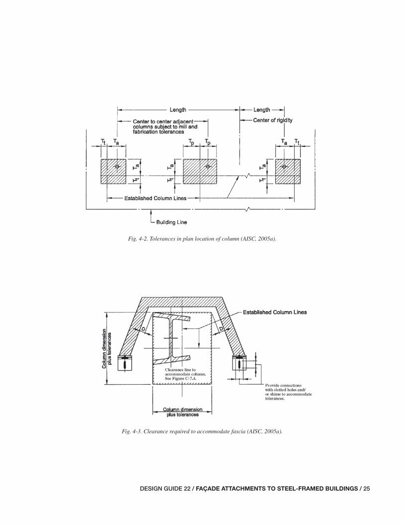
DESIGN GUIDE 22 / FAÇADE ATTACHMENTS TO STEEL-FRAMED BUILDINGS / 25
Fig. 4-2. Tolerances in plan location of column (AISC, 2005a).
Fig. 4-3. Clearance required to accommodate fascia (AISC, 2005a).
017-030_DG22_Ch04.indd 25 7/17/08 3:07:00 PM

26 / FAÇADE ATTACHMENTS TO STEEL-FRAMED BUILDINGS / DESIGN GUIDE 22
Fig. 4-4. Clearance required to accommodate accumulated column tolerance (AISC, 2005a).
017-030_DG22_Ch04.indd 26 7/17/08 3:07:01 PM

DESIGN GUIDE 22 / FAÇADE ATTACHMENTS TO STEEL-FRAMED BUILDINGS / 27
Fig. 4-5. Exterior column plumbness tolerances normal to building (AISC, 2005a).
017-030_DG22_Ch04.indd 27 7/17/08 3:07:01 PM

28 / FAÇADE ATTACHMENTS TO STEEL-FRAMED BUILDINGS / DESIGN GUIDE 22
The cumulative tolerance for the elevation of a point at mid-span of a spandrel beam is composed of the allowable variation of the beam work point down from the upper col-umn splice line (c-in. up and x-in. down from theoretical location) and the allowable variation in camber. The column splice line elevation is based on cumulative tolerances of the base plate elevation and fabricated member length toler-ances. The maximum variation of the top of the base plate relative to the bearing surface is 8 in., up or down. The col-umn fabrication tolerances vary depending on length and connectivity to other structural steel members, but are under no condition greater than 8 in.
Adjustable Items
As required in Section 7.13.1.3, adjustable items must be designated as adjustable in the contract documents. Thus, the designer should clearly identify in the contract documents items that are intended to be adjustable, such as shelf angles, slab edge elements, and similar supporting members for other trades, and provide the total adjustability required for proper alignment. Section 7.13.1.3 in the AISC Code of Standard Practice permits a variation for adjustable items of plus or minus a in. in both the vertical and horizontal directions.
The AISC Code of Standard Practice also requires that designers provide the necessary clearances and adjustments for materials furnished by other trades to accommodate the steel tolerances defi ned in the Code. Furthermore the Code requires the “Owner’s Designated Representative for Con-struction” to check the fi nal steel location prior to placing or installing façade elements.
4.3 FAÇADE MATERIAL AND ERECTION TOLERANCES
Numerous tolerances apply to the façade systems discussed in this Design Guide, however only those that relate most signifi cantly to the attachment of façades to steel structures are outlined below. The references in which these tolerances are listed also include various product tolerances that may be helpful to designers of façade systems.
4.3.1 Brick Veneer Tolerances
Brick veneer assembly tolerances, as defi ned by ACI 530 (ACI et al., 2005), are relatively small compared to those for the structural frame. They are:
Fig. 4-6. Tolerances in plan at any splice elevation of exterior columns (AISC, 2005a).
017-030_DG22_Ch04.indd 28 7/17/08 3:07:01 PM

DESIGN GUIDE 22 / FAÇADE ATTACHMENTS TO STEEL-FRAMED BUILDINGS / 29
Elements:
Variation from plumb
• ± 4 in. in 10 ft
• ± a in. in 20 ft
• ± 2 in. max.
True to a line
• ± 4 in. in 10 ft
• ± a in. in 20 ft
• ± 2 in. max.
Location of Elements:
Indicated in plan
• ± 2 in. in 20 ft
• ± a in. max.
Indicated in elevation
• ± 4 in. in story height
• ± w in. max.
4.3.2 Precast Concrete Panel Tolerances
The Precast/Prestressed Concrete Institute (PCI) provides its Tolerance Manual for Precast and Prestressed Concrete Construction, (PCI, 2000), which is widely referenced for product and erection tolerances. Additionally, precast-concrete panel tolerances are defi ned in the PCI Design Handbook (PCI, 2004) as follows:
Plan Location:
From building grid datum
• ± 2 in.
From centerline of steel support (takes precedence over di-mension from grid datum)
• ± 2 in.
Support Elevation:
From nominal elevation
• – 2 in.
• + 4 in.
Elements:
Variation from plumb (minimum of height of structure or 100 ft)
• ± 1 in.
Variation from plumb (in any 10 ft)
• ± 4 in.
Warping variation from nearest adjacent corner
• ± z in. per ft
Bowing per panel
• L/360
Differential bowing of panels of the same design
• 2 in.
4.3.3 Aluminum Curtain Wall Tolerances
The American Architectural Manufacturers Association (AAMA) provides guidance in Installation of Aluminum Curtain Walls (AAMA, 1989a) and Metal Curtain Wall Manual (AAMA, 1989b), which specify tolerances for alu-minum curtain walls as follows:
Elements:
Bowing standard mill tolerance for extruded aluminum
• 4 in. in 20-ft length
Twisting standard mill tolerance for extruded aluminum
• 5° in 20-ft length
Location of Elements:
Variation from plane or location shown on approved shop drawings
• 8 in. per 12 ft
• 2 in. in any total length
Maximum offset from true alignment between two identical members abutting end to end in line
• z in.
017-030_DG22_Ch04.indd 29 7/16/08 4:55:12 PM
30 / FAÇADE ATTACHMENTS TO STEEL-FRAMED BUILDINGS / DESIGN GUIDE 22
The Construction Sciences Research Foundation (CSRF) provides its SPECTEXT® Master Guide Specifi cation, Sec-tion 08920 “Glazed Aluminum Curtain Wall” (CSRF, 2006), which recommends the following:
Elements:
Variation from plumb (minimum of, noncumulative)
• 0.06 in. per 3 ft
• 2 in. per 100 ft
Misalignment of adjacent members (noncumulative)
• Q in.
4.3.4 GFRC Panel Tolerances
GFRC panel tolerances as defi ned in PCI Recommended Practice for Glass Fiber Reinforced Concrete Panels (PCI, 2001) are as follows:
Plan Location:
From building grid datum
• ± 2 in.
From centerline of steel support (takes precedence over di-mension from grid datum)
• ± 2 in.
Support Elevation:
From nominal elevation
• – 2 in.
• + 4 in.
Elements:
Variation from plumb (minimum of height of structure or 100 ft)
• ± 1 in.
Variation from plumb (in any 10 ft)
• ± 4 in.
Warping variation from nearest adjacent corner
• ± z in. per ft
Bowing per panel
• L/240
Differential bowing of panels of the same design
• 4 in.
4.3.5 EIFS Panel Tolerances
There are few standards for EIFS panel tolerances, but Exterior Insulation and Finish Systems Design Handbook (Thomas, 1992) suggests the following:
Elements:
Offset from surface plane of adjacent panels
• ± z in. and not discernible from a distance of more than 6 ft when viewed perpendicular to panel faces
Corner to corner squareness
• ± 8 in.
017-030_DG22_Ch04.indd 30 7/16/08 4:55:12 PM

DESIGN GUIDE 22 / FAÇADE ATTACHMENTS TO STEEL-FRAMED BUILDINGS / 31
Chapter 5 Design of Slab Edge Conditions for Façade Attachments
5.1 GENERAL APPROACHES
The slab edge detail is an important consideration when designing the façade attachments. Factors that infl uence the design approach include:
• The type of façade and its location relative to the steel frame;
• How far the slab and/or deck overhangs the spandrel beams;
• The strength of the slab or deck, and the degree to which the designer wishes to count on the slab or deck for façade attachment;
• Whether or not the façade loads are applied directly to the slab or deck; and,
• The degree to which the edge condition is similar throughout the project.
Of these, the degree to which the designer wishes to count on the slab or deck to support loads has the most infl uence on the approach and detail. There are two fundamental ap-proaches for designing the slab edge. First, the slab or deck can be cantilevered over the spandrel beam to carry any loads applied to the slab or deck overhang. Alternatively, and second, the designer can ignore the slab or deck as a cantilever and apply the loads to the overhang with a steel plate or assembly.
Generally speaking, counting on the slab or deck to carry the loads as a cantilever is the most economical approach if the typical slab or deck can provide the strength necessary for the given overhang and loads. It is usually not economi-cal to increase the typical slab or deck thickness just for the overhang condition. When the overhang and/or loads are large relative to the slab strength, the designer may neglect the strength of the slab or deck and add a bent plate or other structural steel assembly attached to the spandrel beam to resist the loads at the slab edge.
There may be other project conditions that compel the de-signer to neglect the slab or deck strength as a cantilever. Some examples are:
• When there is no concrete slab and the metal deck is parallel with the spandrel beam;
• When slab depressions and openings in the back-span make counting on the cantilever problematic for too many locations;
• When the designer anticipates quality control issues with the concrete slab strength and placement; and,
• When the façade attachment details dictate a heavy bent plate for attachment anyway.
Figure 5-1 illustrates a slab designed as a cantilever over-hanging the spandrel beam. The overhanging slab, as well as the back span, which is the fi rst interior span of slab, must have shear and fl exural strength suffi cient for the loads. This approach has the added benefi t of resolving the eccen-tricities of the slab edge loads without creating torsion in the spandrel beam. For these practical and economical reasons, the designer should include the slab and deck in the sup-port system, when possible. A bent plate or light-gage metal pour stop is still needed until the concrete reaches adequate strength.
Façade attachment loads to the slab edge will generally include vertical forces, FV, and horizontal forces, FH. In addition, depending on the fi xity of the connection of the attachment clips to the façade, the attachment forces may include a moment, Mef, due to the eccentricity between the vertical forces at the center of gravity of the façade system and the edge of the slab.
Note that the horizontal force, FH, is shown in Figure 5-1 as a tension force, indicating that the façade panel is hung from this support at its top. Were the panel instead supported at its bottom, FH would be a compressive force.
Figure 5-2 illustrates the concepts where the SER designs a steel edge member, such as a bent plate, to transfer the loads at the slab edge to the spandrel. The slab and/or deck are not designed for shear or fl exure from the overhang. However, either may be designed for any in-plane horizontal forces that the façade attachments may deliver to the slab. In this approach, the spandrel will have torsion applied to it due to the eccentricity between the spandrel web and the loads at the slab edge.
The applied torsion must be resolved by the support con-ditions of the spandrel, or another means. Given that wide-fl ange shapes are very economical, but not very effi cient at resisting torsion, it is usually best to eliminate the torsion by framing beams or kickers into the spandrel at the locations
031-070_DG22_Ch05.indd 31 7/16/08 4:42:29 PM
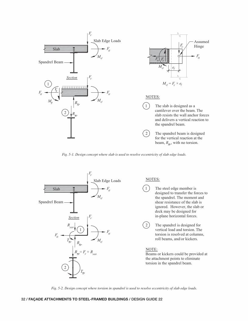
32 / FAÇADE ATTACHMENTS TO STEEL-FRAMED BUILDINGS / DESIGN GUIDE 22
Fig. 5-1. Design concept where slab is used to resolve eccentricity of slab edge loads.
Fig. 5-2. Design concept where torsion in spandrel is used to resolve eccentricity of slab edge loads.
031-070_DG22_Ch05.indd 32 7/16/08 4:42:30 PM

DESIGN GUIDE 22 / FAÇADE ATTACHMENTS TO STEEL-FRAMED BUILDINGS / 33
of the façade attachments to resist the moment and eliminate the torsion on the spandrel entirely. This requires coordina-tion with the architecture and mechanical systems, which may limit the use of these solutions. If so, these elements can be used in acceptable locations to limit the length of the spandrel beam to restrain the twist.
When the spandrel is a girder, the fl oor beams spanning into the spandrel are usually capable of restraining the twist, provided that the connections to the girder are capable of transferring the moment and are not too fl exible. When the fl oor beams are parallel to the spandrel, one option is to add sub-framing perpendicular to the spandrel between the span-drel and the fi rst interior fl oor beam. These sub-beams are sometimes referred to as “roll beams.” The other option is to add kickers between the bottom fl ange of the spandrel and either the top fl ange of an interior fl oor beam or an anchored connection to the slab. In both options, if the designer con-siders the spandrel connections to the columns as additional points of restraint, the design of the connection to the col-umn must address torsion and fl exibility. Figures 5-3 and 5-4 provide a closer look at the load path to restrain torsion in the spandrel beam using roll beams and kickers, respectively.
Whether the designer is counting on the slab to cantile-ver over the spandrel, or is designing the spandrel beam for torsion, successful design requires careful attention to the load path through the components and connections, as well as attention to those elements that contribute to the overall defl ection of the slab edge. The following sections provide guidance for considering these issues when designing slab edge details.
5.2 SLAB EDGE DETAILS WITH LIGHT-GAGE METAL POUR STOPS
One of the most economical slab edge details incorporates a light-gage metal pour stop. Usually made of cold-formed steel of 10 to 20 gage, the pour stop is part of the metal decking procurement package and is welded to the spandrel beam in the fi eld during erection of the metal deck. Figure 5-5 presents a typical light-gage metal pour stop detail.
As the name implies, the sole purpose of the pour stop is to form the edge of the concrete slab. As published by the Steel Deck Institute (SDI, 2000) and provided by many deck manufacturers in their catalogues, the design of the pour stop is for the weight of the wet concrete, concrete fl uid pressure on the vertical leg, and a uniform construction live load of 20 psf. The SER must design the concrete slab to carry all superimposed dead and live loads after the concrete is cured. Therefore, the use of the light-gage metal pour stop is generally limited to the following conditions:
• The adjusted overhang, measured from the fl ange tip, is 12 in. or less;
• The confi guration of the slab and its reinforcement is such that it has the strength to resist all superimposed loads on the overhang, including façade attachment loads, if any; and,
• If the overhang carries any façade attachment loads, the load path must be directly into the slab and not through the pour stop itself. The light-gage metal pour stop rarely has the strength required for façade attachments. Fur-thermore, if steel embedment plates are cast into the slab for façade attachment, only very heavy-gage pour stops are stiff enough to secure the embedment plates to them for positioning in the slab.
When using light-gage metal pour stops, the designer must provide for support of the pour stop at columns and corners of the slab edge.
5.2.1 Design of Light-Gage Metal Pour Stops
Figure 5-6 outlines the design approach for the cold-formed, light-gage metal pour stop. The pour stop is designed as a cantilever with the critical moment location at the tip of the spandrel beam fl ange. The wet concrete loads include the wet weight of the concrete as a uniform load over the horizontal leg and an equivalent fl uid pressure, equal to the wet weight of the concrete, applied to the vertical leg. An additional construction live load of 20 psf is applied as a uni-form load over the horizontal leg. Generally, a concentrated construction live load is not considered for light-gage metal pour stops.
Common designs call for the pour stop to overlap the spandrel fl ange by 2 in. The back edge of the pour stop is welded to the top of the spandrel fl ange. Bearing at the tip of the spandrel fl ange is used to transmit the shear from the cantilever. A force-couple formed between this bearing force at the fl ange tip and an equal and opposite transverse force in the weld resolve the cantilever moment.
Designers can specify the pour stop as an adjustable item and specify the maximum and minimum overlap of the pour stop with the spandrel beam fl ange. This will allow fi eld ad-justment of the pour stop to address some of the steel frame tolerances. For instance, if the maximum anticipated ad-justment at a particular spandrel is 1 in., and a minimum of 2 in. of bearing is required for the pour stop, the overlap can be specifi ed as ranging between a minimum of 2 in. and a maximum of 4 in.
Light-gage metal pour stops are generally made from material with specifi ed minimum yield strength, Fy, of 33 ksi. SDI recommends that the designer limit the design fl exural stress to 20 ksi for the wet concrete load, tempo-rarily increased by one-third for the additional construction live load. SDI also recommends limiting the horizontal and
031-070_DG22_Ch05.indd 33 7/16/08 4:42:32 PM

34 / FAÇADE ATTACHMENTS TO STEEL-FRAMED BUILDINGS / DESIGN GUIDE 22
Fig. 5-3. Design concept using roll beam to resolve torsion in spandrel from slab edge loads.
Fig. 5-4. Design concept using kickers to resolve torsion in spandrel from slab edge loads.
031-070_DG22_Ch05.indd 34 7/16/08 4:42:32 PM

DESIGN GUIDE 22 / FAÇADE ATTACHMENTS TO STEEL-FRAMED BUILDINGS / 35
Fig. 5-5. Light-gage metal pour stop detail.
Fig. 5-6. Design approach for light-gage metal pour stop.
031-070_DG22_Ch05.indd 35 7/16/08 4:42:33 PM

36 / FAÇADE ATTACHMENTS TO STEEL-FRAMED BUILDINGS / DESIGN GUIDE 22
vertical defl ection of the tip of the vertical leg to 4 in. This guidance is incorporated into Table 5-1 (see end of chapter), which provides a pour stop selection table (used with per-mission of SDI).
Example 5.1 illustrates light-gage metal pour stop selec-tion using this table.
5.2.2 Design of Slab Overhang Made with Light-Gage Metal Pour Stop for Superimposed Loads
When using slab edge details made with a light-gage metal pour stop, designers must design the concrete slab to carry all superimposed dead and live loads after the concrete is cured. As a practical matter, the concrete weight generally is included, thereby making the pour stop a stay-in-place form not necessary for the performance of the cured slab.
The slab overhang is generally designed as a cantilever with the back span being formed by the span of the slab between the spandrel and the next interior beam or girder. The critical section for the design of the slab is usually on the back-span side of the spandrel due to the effec-tive width or depth reductions from the fl utes of the metal deck. Figure 5-7 illustrates the effective width and depth reductions. The most important of these reductions is the
depth reduction that occurs on the back-span side when the fl utes of the deck are parallel with the spandrel beam. It is not unusual for this to result in depths that are one half of the overhanging slab depth.
If the overhang is to carry any façade attachment loads, the load path to the slab should be through direct bearing. The light-gauge metal pour stop itself is ineffective as a re-ceptor of welded façade attachments. If the façade attach-ments are applied to the slab overhang, they may very well be concentrated loads, and the designer must determine the effective width of the slab for checking the strength. A con-servative but customary assumption is to assume a critical width equal to the actual width of the applied load plus two times the distance from the load to the section of interest, as illustrated in Figure 5-8.
Slab overhangs and back spans can be designed using ACI 318 (ACI, 2004) requirements for reinforced concrete slabs. If façade loads are applied to the slab edge on the overhang, these loads will usually control the design of the top rein-forcement in the slab at these locations, and it is not unusual for designs to call for additional deformed bars in the top of the slab.
Tables 5-2 through 5-9 provide slab fl exural strengths for various slab thicknesses, deck heights, deck orientations, and concrete strengths and slab reinforcement weights.
Fig. 5-7. Effective depths of slabs on metal deck at slab edge.
031-070_DG22_Ch05.indd 36 7/16/08 4:42:34 PM

DESIGN GUIDE 22 / FAÇADE ATTACHMENTS TO STEEL-FRAMED BUILDINGS / 37
Example 5.2 illustrates the design of a concrete slab over-hanging a spandrel beam and reinforced to support façade loads.
5.3 SLAB EDGE DETAILS WITH STRUCTURAL STEEL BENT PLATES OR OTHER STEEL EDGE MEMBERS
There are at least three cases when designers might choose to use a bent plate or other structural steel element at the slab edge instead of a light-gage metal pour stop:
• Case 1—The overhang is larger than what is appropriate for a light-gage metal pour stop. In this case, the slab or deck can be used to carry any loads on the overhang and a bent plate can be used only as a pour stop. Façade attachments will be made directly to the slab, or to an embedment plate in the slab.
• Case 2—The same as Case 1, except a structural steel bent plate (or similar steel element) is used as a means to attach the façade elements to the slab. As one example, headed studs can be used on the vertical leg of the bent plate embedded in the slab with fi eld-welded façade attachment clips attached to the plate after the slab is placed.
• Case 3—The slab and/or deck do not have adequate strength or stiffness for the overhang loads and a bent plate or other edge element will serve as the structural means to transmit the loads from the overhang back to the spandrel beam. As described earlier, this results in eccentric loads on the spandrel that the designer must address.
Case 3 generally occurs at roof framing without slabs, or at fl oor framing made of open web joists or otherwise in-corporating thin slabs or metal decks where the concrete is just a fi ll and not considered a structural element. Section 5.1 provides other project conditions that might compel the designer to neglect the slab or deck strength as a cantilever.
A variation of Case 3 is the condition where the designer neglects the transverse shear and fl exural strength of the slab overhang and designs the bent plate to carry these forces, but accounts for strength of the slab to take in-plane forces. In this case the designer can use a headed stud or deformed bar anchor to transfer the horizontal façade forces into the plane of the slab where any tension can be carried by the slab reinforcement.
A bent plate is often used in any of these cases. Minimum thicknesses are generally x in., and maximum thicknesses are generally 2 in., limited by the bending equipment ca-pacity in the shop or fi eld handling of the pieces if they are not shop attached to the spandrel beam. Designers should be aware that as thicknesses increase, the practical lengths of the plates get shorter. The limits are shop and erector specifi c, but it is not uncommon for 2-in. plates to be held to 10-ft lengths. Therefore, there may be three lengths of plate on a 30-ft spandrel beam, and designers must decide if a con-nection is required between such segments of plate along a single spandrel beam.
Hot-rolled angles have two advantages over the bent plate. First, they do not have the same length limitations. Second, their shape tolerances are much tighter; the angle between the legs is more consistently 90 degrees and the tips of the
Fig. 5-8. Effective width for concentrated loads at slab edge.
031-070_DG22_Ch05.indd 37 7/16/08 4:42:35 PM

38 / FAÇADE ATTACHMENTS TO STEEL-FRAMED BUILDINGS / DESIGN GUIDE 22
outstanding legs are straighter. However, the necessary ge-ometry for the detail is often such that the designer cannot choose an angle, either because the needed leg sizes do not exist or, if they do, the available thickness is much greater than needed. Additionally, the designer should consider roll-ing tolerances of angles including their sweep.
The bent plate or angle can be applied to the spandrel beam in the shop or fi eld, or shop applied and fi eld adjusted. By far, the most economical approach from the perspective of steel fabrication and erection is to simply shop-attach the bent plate or angle. However, tolerances and clearances for the façade must then be accounted for by other means, such as in the façade attachment clips. When designing a detail that allows shop attachment and fi eld adjustment, the de-signer must consider the following:
• The needed outward and inward adjustment;
• The spandrel beam fl ange width, realizing that the most economical spandrel beam shape may vary throughout the project and thus change the fl ange width;
• The minimum overlap between the plate and fl ange needed for the connection;
• What the maximum overlap between the plate and fl ange may be and ensure this does not cause interference with other construction, such as installation of headed studs; and,
• The lengths of slotted holes and the hole edge distances to the tips of the fl ange and edges of the plate.
Figure 5-9 provides some example connection details for bent plates on spandrel beams.
As with light-gage metal pour stops, the designer must provide for support of the pour stop at columns and corners of the slab edge.
5.3.1 Case 1—Bent Plate Used as a Pour Stop Only
When the overhang is larger than what is appropriate for a light-gage metal pour stop, a bent plate can be used to form the edge of slab. If the slab is designed to carry the superim-posed loads and the plate is not a means to attach the façade to the slab, its sole purpose is to serve as a pour stop, and the design of the plate is similar to that for the light-gage metal pour stop.
As with light-gage metal pour stops, the design of the bent plate pour stop is for the weight and lateral fl uid pressure of the wet concrete, and for a uniform construction live load of 20 psf. Consider limiting the vertical and horizontal defl ec-tion of the tip of the up-turned leg to less than 8 in. when subjected to the wet concrete load (this defl ection limit is a judgment and designers may choose another limit, such as
4 in. as is used in the SDI table for light-gage metal pour stops). If the overhang gets larger than about 12 in., design-ers should consider also checking the plate for a concentrat-ed construction load of at least 250 pounds at the tip in place of the uniform construction live load of 20 psf.
Tables 5-10 and 5-11 provide design aids for selecting bent plates for unstiffened pour stops.
Example 5.3 illustrates the design of a bent plate pour stop.
5.3.2 Case 2—Bent Plate Used as a Pour Stop and a Means of Attaching the Façade to the Slab
A situation where the designer may choose a bent plate over a light-gage metal pour stop is when the designer wishes to use the bent plate as a means to attach the façade to the slab. The slab is still reinforced to carry the superimposed loads, including façade loads, applied to the overhang. A fi eld-applied headed stud or deformed bar anchor is usually welded to the vertical leg of the bent plate.
The bent plate may be a means to attach an embedment plate for the façade attachments. Sample details are shown in Figure 5-10. Headed studs and embedment plates that are located within or protrude into the width of the beam fl ange must be fi eld welded to conform to the OSHA steel erection rules for tripping hazards.
As discussed in Section 5.1, façade attachment loads to the slab edge will generally include vertical forces, FV, and horizontal forces, FH. In addition, depending on the fi xity of the connection of the attachment clips to the façade, the attachment forces may include a moment, Mef, due to the eccentricity between the vertical forces at the center of grav-ity of the façade system and the edge of the slab. Figure 5-11 illustrates the design concept where a headed stud on the vertical leg of a bent plate transfers the façade attachment forces to the slab. The headed stud (or deformed bar anchor if the designer so chooses) must be capable of transferring shear and tension to the concrete slab. The headed stud shear and pullout strengths must account for the edge distances that are present.
Tables 5-12 through 5-15 are design aids that provide shear and tension strength values for headed studs in the edges of concrete slabs.
Example 5.4 illustrates the design of a bent plate pour stop that is also used as a means to attach the façade, with loads transmitted to slab reinforcement with headed studs.
5.3.3 Case 3—Bent Plate Transmits the Overhang Loads; the Slab Transverse Shear and Flexural Strength Are Neglected
The SER sometimes cannot count on the slab or deck to carry the loads on the slab overhang because of depressions or penetrations in the back span. With long overhangs and/or large loads, such as precast-concrete panel weights, the bent
031-070_DG22_Ch05.indd 38 7/16/08 4:42:35 PM

DESIGN GUIDE 22 / FAÇADE ATTACHMENTS TO STEEL-FRAMED BUILDINGS / 39
Fig. 5-9. Example details for connection of bent plate to spandrel beam.
031-070_DG22_Ch05.indd 39 7/16/08 4:42:35 PM

40 / FAÇADE ATTACHMENTS TO STEEL-FRAMED BUILDINGS / DESIGN GUIDE 22
plate, or other edge assembly, can be designed to transfer the overhang loads to the spandrel. This will inevitably apply some torsion to the spandrel and the designer must assess the impact of this on the spandrel design.
Although there may be conditions where the transverse shear and fl exural strength of the slab overhang must be neglected, horizontal forces usually can be transferred to the slab with a headed stud or deformed bar anchor on the
Fig. 5-10. Typical detail of steel edge member as pour stop and façade attachment.
Fig. 5-11. Concept where steel assembly forms pour stop and means to attach façade.
031-070_DG22_Ch05.indd 40 7/16/08 4:42:36 PM

DESIGN GUIDE 22 / FAÇADE ATTACHMENTS TO STEEL-FRAMED BUILDINGS / 41
Fig. 5-12. Design concept for slab edge detail where slab is neglected except for in-plane forces.
Fig. 5-13. Transfer of horizontal façade force to the slab edge.
back of the vertical leg, thereby eliminating or reducing the bending in the bent plate. Figure 5-12 illustrates this con-cept. Note that there must be a load path for these in-plane forces to get to the main slab diaphragm of the structure.
Figure 5-13 illustrates the transfer of the façade horizontal force to the slab.
The length of the headed stud should be such that it extends into the slab a suffi cient distance to allow transfer of the force
031-070_DG22_Ch05.indd 41 7/16/08 4:42:38 PM

42 / FAÇADE ATTACHMENTS TO STEEL-FRAMED BUILDINGS / DESIGN GUIDE 22
to the slab reinforcement. Slab bars with 180-degree hooks can be used to reduce the development length of the slab bars; when the resulting hook depth does not fi t within the slab vertically, the bar can be rotated from vertical. If necessary, deformed bar dowels can be attached to the back of the plate with threaded couplers welded to the plate. This allows for longer lap lengths to develop the force into the slab.
For large overhangs and/or large loads, the required thick-ness of a bent plate may become impractical (it is the au-thor’s experience that 2 in. is the limit of practical bent plate thickness). Figure 5-14 shows slab edge details that can be used in such a case.
As the plate becomes thick and/or requires stiffeners for the applied façade loads, and the overhang is less than 12 in., the designer may want to provide separate brackets or other steel assemblies from the spandrel beam to support the façade loads and allow a light-gage metal pour stop to form the edge of slab.
Example 5.5 illustrates the design of a bent plate pour stop supporting a façade with the slab strength ignored.
Example 5.6 is similar to Example 5.5, except welded bar couplers and threaded reinforcing bars are used to transmit out-of-plane forces only to the slab.
Example 5.1—Light-Gage Metal Pour Stop Selection
For the light-gage metal pour stop illustrated in Figure 5-15, determine the required thickness based on the maxi-mum slab overhang.
Given:The slab is composed of normal-weight concrete (wc = 150 lb/ft3), and the spandrel beam is a W18×50. The architect has set the slab edge at 12 in. from the centerline of the spandrel beam; thus, leos = 12 in. The deck height, hd = 2 in. The total slab height, hs = 6 in. Solution:The spandrel beam fl ange width, bf = 7.50 in. The slab over-hang is,
l lb
oh eosf
=2
= in.in.
2
−
−127 50.
= 8.25 in.
Using Table 5-1, with an 84-in. overhang and a 6-in. slab depth, a 10-gage pour-stop thickness is required.
Use a 10-gage pour stop thickness.
Example 5.2—Concrete Slab Overhanging a Spandrel Beam and Reinforced to Support a CMU Wall
For the concrete slab supporting a concrete masonry unit
(CMU) wall and overhanging a spandrel beam as illustrated in Figures 5-16 (deck perpendicular) and 5-17 (deck paral-lel), determine the adequacy of the slab and design the re-quired reinforcement for the following conditions:
Condition A. Deck perpendicular to the spandrel beam as shown in Figure 5-16.
Condition B. Deck parallel to the spandrel beam as shown in Figure 5-17.
Given:For this example, assume that the controlling strength load combination is 1.4D.
The slab edge is formed with a light-gage metal pour stop that does not contribute to the slab overhang strength. The slab is composed of normal-weight concrete (wc = 150 lb/ft3; f 'c = 3,000 psi), the CMU wall is 8-in. thick (wblk = 61 psf), and the story height, h = 14 ft. The architect has specifi ed a 1-in. planned reveal under the CMU wall at the end of the slab overhang to provide for an inward or out-ward tolerance of 1 in. for the face of block, which results in a worst-case reveal of 2 in.
The architect has set the slab edge such that the distance from the slab edge to the tip of the spandrel beam fl ange, loh = 10 in. The deck height, hd = 2 in. The total slab height, hs = 42 in.
The reinforcing steel has fy = 60 ksi and clear cover, cc = 1 in.
Solution:Because the slab cantilevers over the spandrel beam, the CMU wall load does not induce torsion in the spandrel beam. The required fl exural strength in the slab overhang due to slab self-weight is,
Mw h l
u swc s oh= 1.42
= 1.4
2⎛⎝⎜
⎞⎠⎟
((0.150 kip/ft ) in. 10 in.
2 12 in./ft
3 4 22( )( )(( )
⎛
⎝⎜⎞
⎠⎟2
= 0.328 kip-in./ft
The weight of the CMU wall (conservatively using the full 14-ft story height) is,
P w hblk blk=
= 0.061 kip/ft (14 ft)2
= 0.854 kip/ft
Based upon the width of the CMU wall, bblk = 7s in., and the worst-case reveal of 2 in., the moment arm for the wall load
031-070_DG22_Ch05.indd 42 7/16/08 4:42:39 PM

DESIGN GUIDE 22 / FAÇADE ATTACHMENTS TO STEEL-FRAMED BUILDINGS / 43
Fig. 5-14. Design concept for slab edge detail where slab is neglected except for in-plane forces and brackets are used.
031-070_DG22_Ch05.indd 43 7/16/08 4:42:39 PM
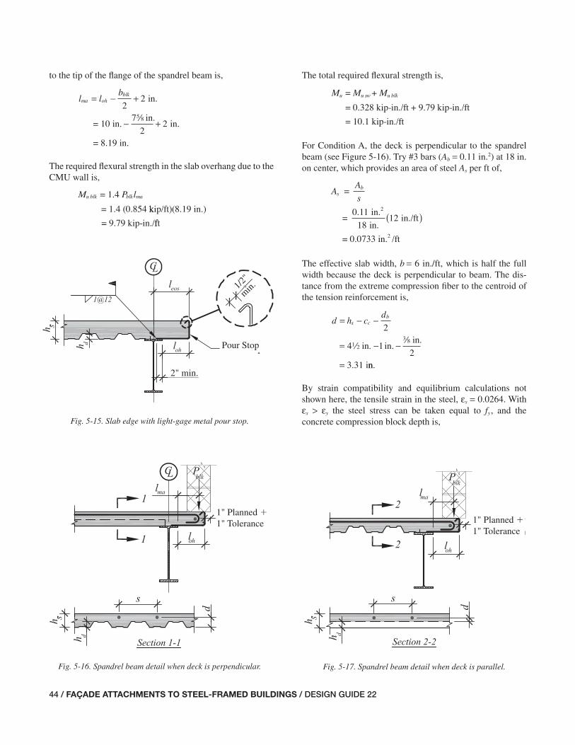
44 / FAÇADE ATTACHMENTS TO STEEL-FRAMED BUILDINGS / DESIGN GUIDE 22
Fig. 5-17. Spandrel beam detail when deck is parallel.
1" Planned �1" Tolerance
Fig. 5-15. Slab edge with light-gage metal pour stop.
Fig. 5-16. Spandrel beam detail when deck is perpendicular.
Pour Stop
2" min.
1/2"
min.
1" Planned �1" Tolerance
to the tip of the fl ange of the spandrel beam is,
= −l lb
ma ohblk +
− +
22
2
in.
= 10 in.7 in.
2
sin.
= 8.19 in.
The required fl exural strength in the slab overhang due to the CMU wall is,
M P lu blk blk ma= 1.4
= 1.4 (0.854 kkip/ft)(8.19 in.)
= 9.79 kip-in./fft
The total required fl exural strength is,
= +M M Mu u sw u blk
= 0.328 kip-in./ft + 9.79 kip-in./ft
= 10.1 kip-in./ft
For Condition A, the deck is perpendicular to the spandrel beam (see Figure 5-16). Try #3 bars (Ab = 0.11 in.2) at 18 in. on center, which provides an area of steel As per ft of,
AA
ss
b=
=0.11 in.
in.in./ft
2
1812( )
= 0.0733 in. /ft2
The effective slab width, b = 6 in./ft, which is half the full width because the deck is perpendicular to beam. The dis-tance from the extreme compression fi ber to the centroid of the tension reinforcement is,
d h cd
s cb= − −
= −
=
.2
42
in. in.in
3.31
−1
i
2a
nn.
By strain compatibility and equilibrium calculations not shown here, the tensile strain in the steel, εs = 0.0264. With εs > εy the steel stress can be taken equal to fy, and the concrete compression block depth is,
031-070_DG22_Ch05.indd 44 7/16/08 4:42:40 PM

DESIGN GUIDE 22 / FAÇADE ATTACHMENTS TO STEEL-FRAMED BUILDINGS / 45
aA f
f b
s y
c
=
=(0.0733 in. /ft)(60 ks2
0 85. '
ii)
(3 ksi)(6 in./ft)
= in.
0 85
0 287
.
.
Thus,
M A f d
0.90 (sinceφ ε
φ φ
= >
=
s
n s y
0 005. )
−−⎛⎝⎜
⎞⎠⎟
= ( )
a
2
0 9 0 0733 in. /ft 60 k2. . ssi in.in.( ) −⎛
⎝⎜⎞⎠⎟
=
3 310 287
2
12
..
.55 kip-in./ft ≥ Mu o.k.
From calculations not shown here, the development length of the hooked ends does not control in this case. For illustra-tion of this check, see Example 5.4. Note that the slab rein-forcement also must be fully developed on the other side of the point of maximum moment.
Use #3 reinforcing bars at 18 in. o.c. for Condition A.
Alternatively, Tables 5-2 through 5-9 provide the fl ex-ural strength based on concrete compressive strength, deck height, deck orientation, total slab thickness, and amount of reinforcement. The use of these tables will be illustrated in the solution that follows for Condition B.
For Condition B, the deck is parallel to the spandrel beam (see Figure 5-17). Using Table 5-2, #3 reinforcing bars at 8 in. o.c. provide
φMn = 10.2 kip-in. ≥ Mu o.k.
Use #3 reinforcing bars at 8 in. o.c. for Condition B.
Comments:ACI 318-05 utilizes a strain compatibility approach to deter-mine fl exural strength. Also, the resistance factor, φ, is vari-able based upon the strain in the tension steel, εs. For εs less than or equal to εy, φ = 0.65. For εs greater than or equal to 0.005, φ = 0.90. Linear interpolation is used to determine the value of φ between these points.
For brevity, a check of the slab shear strength is not shown in these examples. Designers should verify that the slab has adequate shear strength.
Example 5.3—Bent Plate Pour Stop
For the bent plate pour stop illustrated in Figure 5-18, de-termine the required thickness based on the maximum slab overhang. Use ASTM A36 material for the bent plate (Fy = 36 ksi).
1. Limit the vertical defl ection at the tip of the bent plate pour stop under the wet weight of the concrete to 8 in.
2. Check the strength of the plate using the wet weight of the concrete and a 20-psf construction live load.
3. Check the strength of the plate using the wet weight of the concrete and a 250-lb point load at the edge of the pour stop.
4. Determine the required weld between the pour stop and the beam fl ange.
Given:For this example, use a load factor of 1.6 for the wet concrete weight, bent-plate self weight, and construction live loads, and assume that these are the only loads applied to the bent plate (the slab reinforcing will be designed for all superim-posed loads).
The slab is composed of normal-weight concrete (wc = 150 lb/ft3) and the spandrel beam is a W18×50. The architect has set the slab edge at 18 in. from the centerline of the spandrel beam; thus, leos = 18 in. The total slab height, hs = 7 in. The overlap of the plate to the weld on the beam fl ange, sweld = 2 in.
Solution:The spandrel beam fl ange width, bf = 7.50 in. The slab over-hang is,
l lb
oh eosf= −
= −
=
2
18 in.7.50 in.
214.3 in.
Fig. 5-18. Slab edge with bent plate pour stop.
Bent Plate Pour Stop
Spandrel Beam
Slab Reinforcing Steel(Designed Elsewhere)
1'-6"
7"
2"
031-070_DG22_Ch05.indd 45 7/16/08 4:42:40 PM
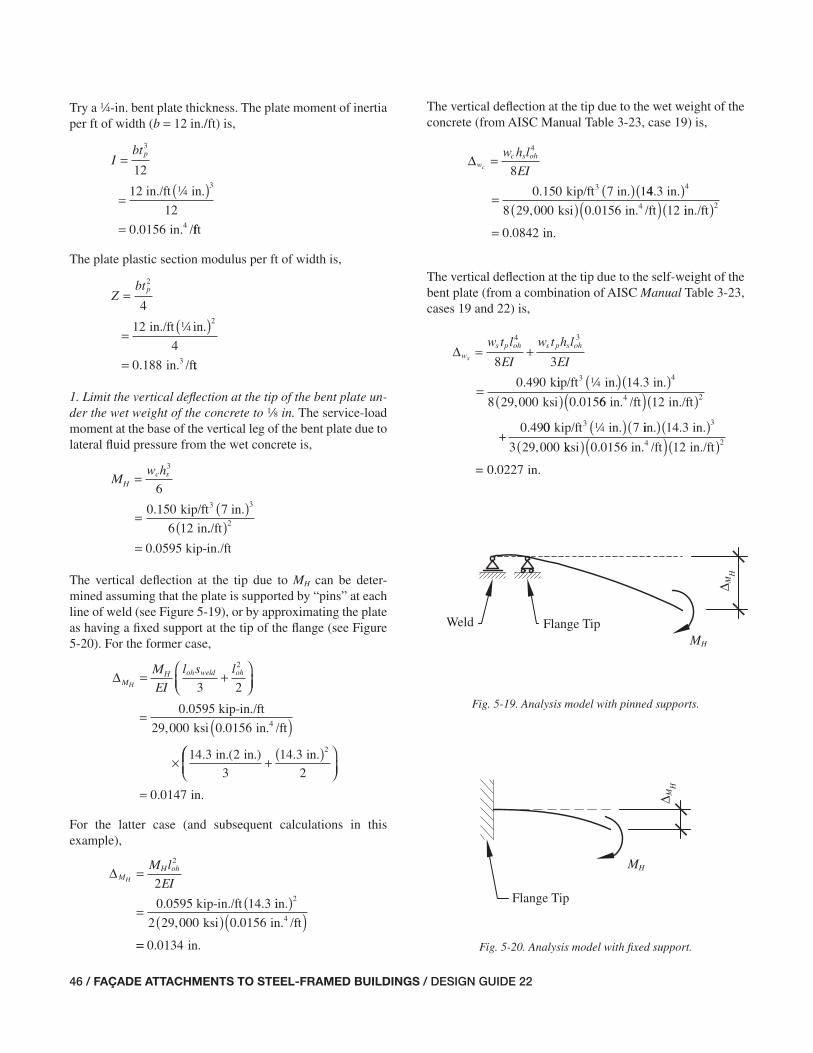
46 / FAÇADE ATTACHMENTS TO STEEL-FRAMED BUILDINGS / DESIGN GUIDE 22
Try a 4-in. bent plate thickness. The plate moment of inertia per ft of width (b = 12 in./ft) is,
Ibtp=
= ( )
=
3
3
12
12
0 0156
12 in./ft in.
in. /4
4
. fft
The plate plastic section modulus per ft of width is,
Zbtp=
= ( )
=
2
2
4
12
4
0 188
in./ft in.
in. /f3
4
. tt
1. Limit the vertical defl ection at the tip of the bent plate un-der the wet weight of the concrete to 8 in. The service-load moment at the base of the vertical leg of the bent plate due to lateral fl uid pressure from the wet concrete is,
Mw h
Hc s=
= ( )
3
3
6
0 150
6 12
kip/ft 7 in.
in
3.
../ft
kip-in./ft
( )=
2
0 0595.
The vertical defl ection at the tip due to MH can be deter-mined assuming that the plate is supported by “pins” at each line of weld (see Figure 5-19), or by approximating the plate as having a fi xed support at the tip of the fl ange (see Figure 5-20). For the former case,
ΔMH oh weld oh
H
M
EI
l s l= +
⎛⎝⎜
⎞⎠⎟
=
3 2
0 0595
2
. kip-in./ft
ksi in. /ft429 000 0 0156, .( )in. in. in.× + ( )14 3 2
3
14 3
2
2. ( ) .⎛⎛⎝⎜
⎞⎠⎟
= in.0 0147.
For the latter case (and subsequent calculations in this example),
M lΔM
H ohH EI
=
=
2
2
0 0595 14 3kip-in./ft. . iin.
ksi in. /ft
( )( )( )
2
42 29 000 0 0156, .
== 0 0134. in.
The vertical defl ection at the tip due to the wet weight of the concrete (from AISC Manual Table 3-23, case 19) is,
Δwc s oh
c
w h l
EI=
= ( )
4
8
0 150 1kip/ft 7 in.3. 44 3
8 29 000 0 0156 12
4.
, .
in.
ksi in. /ft4
( )( )( ) iin./ft
in.
( )=
2
0 0842.
The vertical defl ection at the tip due to the self-weight of the bent plate (from a combination of AISC Manual Table 3-23, cases 19 and 22) is,
ws p oh ps s oh
s
w t l
EI
w t h l
EI= +
=
4
8 3
0 490 k. iip/ft in. in.
ksi
3
3
4( )( )( )
14 3
8 29 000 0 015
4.
, . 66 12
0 49
2in. /ft in./ft
+
4( )( ). 00 14 3
3 29 000
3kip/ft in. i7 in. in.3 4( )( )( ).
, kksi in. /ft in./ft
=
4( )( )( )0 0156 12 2.
in.0 0227.
Fig. 5-19. Analysis model with pinned supports.
Fig. 5-20. Analysis model with fi xed support.
Flange Tip
Flange TipWeld
Δ MH
MH
MH
Δ MH
031-070_DG22_Ch05.indd 46 7/16/08 4:42:41 PM

DESIGN GUIDE 22 / FAÇADE ATTACHMENTS TO STEEL-FRAMED BUILDINGS / 47
The total vertical defl ection is,
tot M w wH c s= + +
= 0.0134 in. + 0.08422 in. + 0.0227 in.
= 0.120 in. < i8 n. o.k.
2. Check the strength of the bent plate using the wet weight of the concrete and a 20-psf construction live load. The re-quired fl exural strength due to lateral fl uid pressure from the wet concrete is,
M Mu H H
kip-in./ft)
==1 6
1 6 0 0595
.
. ( .
kip-in./ft= 0 0952.
The required fl exural strength due to the wet weight of the concrete is,
Mw h l
u wc s oh
c= 1.6
2
= 1.6
2⎛⎝⎜
⎞⎠⎟
((0.150 kip/ft ) in. 14.3 in.
2 12 in./f
3 7 2( )( )tt
= 1.19 kip-in./ft
( )⎛⎝⎜
⎞⎠⎟2
The required fl exural strength due to the uniform construc-tion live load is,
Mw l
u cllcll oh=
⎛⎝⎜
⎞⎠⎟
=
1 62
1 60 020
2
.
.. kiip/ft in.
(12 in./ft)
2 14 3
2
2.( )⎛⎝⎜
⎞⎠⎟
kip-in./ft= 0 273.
The total required fl exural strength is,
M M M Mu u H u wc ucll= + += kip-in./ft0 0952. ++ kip-in./ft
+ kip-i
1 19
0 273
.
. nn./ft
kip-in./ft= 1 56.
From AISC Specifi cation Section F11, the available fl exural strength is,
φ φb n b yM F Z=
= 0.90 ksi i36 0 188( ) . nn. /ft
= 6.09 kip-in./ft
3( )≥ Mu o..k.
The 1.6FyS limit need not be checked because Z/S = 1.5 for a rectangular plate in bending.
3. Check the strength of the bent plate using the wet weight of the concrete and a 250-lb point load. The effective width, beff, of the pour stop that resists the effects of the 250-lb point load is determined assuming that the load spreads at a 45° angle in both directions. Thus,
b = 2 tan(45°) leff oh
= 2 tan(45°)(14.3 in.)
= 28.6 in.
This approach is conservative because it neglects any in-crease in effective width due to the stiffening effect of the vertical leg of the bent plate, which could be substantial. Al-ternatively, the designer can choose to consider the stiffening effect of the vertical leg.
The required fl exural strength due to the uniform construc-tion live load is,
M P lb
u P c oheff
c=
⎛
⎝⎜⎞
⎠⎟
=
1 612
1
.in./ft
.. . . .6 0 250 14 312
kip inin./ft
28.6 in.( )( ) ⎛
⎝⎜⎜⎞⎠⎟
= kip-in./ft2 40.
The total required fl exural strength is,
M M M Mu u H u w u Pcc= + +
= kip-in./ft0 0952. ++ kip-in./ft
+ kip-in
1 19
2 40
.
. ../ft
kip-in./ft= 3 69.
As calculated previously, the available fl exural strength is,
φb n uM M= 6.09 kip-in./ft ≥ o.k.
Use a 4-in. bent plate pour stop thickness.
4. Determine the required weld between the bent plate pour stop and the spandrel beam fl ange. Try a x-in. fi llet weld with FEXX = 70 ksi. The basic weld strength per AISC Manual page 8-8 is,
φRn = 1.392Dl
where D = weld size in sixteenths of an inchl = length, in.
Note that the loading angle is 90° and a 1.5 weld strength increase factor is also applicable.
031-070_DG22_Ch05.indd 47 7/16/08 4:42:41 PM

48 / FAÇADE ATTACHMENTS TO STEEL-FRAMED BUILDINGS / DESIGN GUIDE 22
The required length of fi llet weld per ft of width (see Figure 5-21) using the larger value of Mu from Parts 2 and 3 of this Example is,
lM
D smin
u
weld
= ( )
=
1 392 1.5
3 6
.
.
kip/in.
99
1 392 1 5 2
kip-in./ft
kip/in. . 3 in.. ( )( )( )in./ft= 0 295.
The minimum permissible fi llet weld length is 12 in. per Specifi cation Section J2.2b.
Use intermittent x-in. fi llet welds, 12-in. long at 12 in. on center.
Comments:The 8-in. defl ection limit used in this example is arbitrary. SDI uses 4 in. for the defl ection criterion of light-gage metal pour stops. The designer should determine appropriate de-fl ection limits based on project conditions. For complete-ness, the defl ection due to the self-weight of the bent plate was included here, although for practical purposes this could be ignored.
The bent plate pour stop in this example could have been selected from Table 5-10 (normal-weight concrete), by en-tering the table with a 7-in. slab thickness and a 14-in. over-hang (beyond the edge of the beam fl ange). The table shows that a 4-in. plate thickness is required. Similarly, Table 5-11 can be used for lightweight concrete.
Use of the 1.6 load factor for both the construction loads and the wet weight of the concrete refl ects the typical prac-tice used to determine tabulated pour stop values in man-ufacturer’s catalogs. The 250-lb construction point load is referenced in Table 1 of SEI/ASCE 37 (ASCE, 2002).
Example 5.4—Bent Plate Pour Stop with Headed Studs Engaging the Slab Reinforcement to Support a Façade
For the bent plate pour stop illustrated in Figure 5-22,
1. Design the headed studs to transfer shear and tension due to the weight of the curtain wall and wind forces.
2. Design the slab fl exural reinforcement.
Given:For this example, assume that the controlling strength load combination is 1.2D + 1.6L + 0.8W.
The slab is composed of lightweight concrete (wc = 115 lb/ft3; f 'c = 4,000 psi), the spandrel beam is a W18×35, and the story height, h = 14 ft. The architect has set the slab edge at 12 in. from the centerline of the spandrel beam; thus, leos = 12 in. The deck height, hd = 3 in. The total slab height, hs = 64 in. Two headed studs are used at each curtain wall attachment point with spacing between them, ss = 12 in. The clear cover between the hooked end of the slab bars and the interior face of the pour stop, cc = w in. (1 in. to the top of slab)
The superimposed dead load, wSIDL = 15 psf. The fl oor live load, wLL = 100 psf. Each attachment supports two stories of curtain wall cladding (wcurt = 15 psf) attached directly to the 4-in.-thick bent plate pour stop at vertical mullions with
Fig. 5-22. Section of slab edge with bent plate pour stop with headed studs acting as façade anchorage.
Attachment at 5 ft o.c.
Slab Reinforcingto be Selected
Headed Studsto be Selected
4" Bent PlatePour Stop
W18×35 Spandrel Beam64" LightweightConcrete on 3"Metal Deck
4"
12"
38"
38"
Fig. 5-21. Analysis model for weld design.
Mu
SweldTu weld
031-070_DG22_Ch05.indd 48 7/16/08 4:42:42 PM

DESIGN GUIDE 22 / FAÇADE ATTACHMENTS TO STEEL-FRAMED BUILDINGS / 49
spacing, sc = 5 ft. The eccentricity between the CG of the curtain wall and the slab edge, ecw = 4 in. (see Figure 5-23). The cladding is exposed to a “components and cladding” wind pressure (or suction), pw = 25 psf. Assume that the cur-tain wall is braced for out-of-plane loads at each fl oor level.
Solution:The spandrel beam fl ange width, bf = 6.00 in. The slab over-hang is,
l lb
oh eosf
=2
12 in.6.00 in.
2
−
−=
== 9.00 in.
1. Design the headed studs to transfer the shear and tension forces. The height of cladding suspended from the spandrel beam is,
h hc =
ft
= 28 ft
2
2 14= ( )
The required strength in tension due to the wind load is,
N F
p hs
u w H
w c
= 0.8
= 0.8
= 0.8 00.025 kip/ft 14 ft 5 ft
= 1.40
2( )( )( )kips
Fig. 5-23. Forces acting on attachments.
FH
FV
FH
FV
FH
FV
ecw
FV × ecw /h
FV × ecw /h
The required strength in shear due to the curtain wall load is,
V F
w h su cw V
curt c c
= 1.2
= 1.2
= 1.2 0.015 kip/ft 28 ft 5 ft2( )( )( )= 2.52 kips
Note that the eccentricity of the curtain wall with respect to the slab edge also creates a horizontal force on the slab, which is,
N Fe
h
Ve
h
u cw Vcw
u cwcw
=
=
=
1 2
2
.
..52 kips4 in.
14 ft 12 in./ft( )⎛⎝⎜
⎞⎠⎟
kip= 0 0600.
This force is usually balanced at each intermediate fl oor by a similar force in compression from the adjacent panel. Even if it were not, the horizontal force in this case is small and has been neglected in subsequent calculations.
With two headed studs at each façade attachment point, ns = 2, and the required tensile and shear strengths per stud are,
NN
nu
u w
s
=
=kips
2= 0.700 ki
1 40.
pp
VV
nu
u cw
s
=
=kips
2= 1.26 kips
2 52.
From Tables 5-14 and 5-15, the design tensile and shear strengths for w-in.-diameter headed studs with a 6-in. em-bedment and a 64-in.-thick lightweight concrete slab are, φNn = 3.27 kips and φVn = 1.93 kips, respectively. Group effects can be ignored because the studs spacing, ss = 12 in., exceeds three times the edge distance (38 in.).
N
Nu
nφ=
kips
3.27 kips
= 0.214
0 700.
031-070_DG22_Ch05.indd 49 7/16/08 4:42:42 PM

50 / FAÇADE ATTACHMENTS TO STEEL-FRAMED BUILDINGS / DESIGN GUIDE 22
V
Vu
nφ=
kips
1.93 kips
= 0.653
1 26.
Because these individual ratios are both greater than 0.2, the interaction of tension and shear must be investigated follow-ing ACI 318-05 Equation D-31.
+ ≤
0.653
V
V
N
Nu
n
u
nφ φ
+ ≤
1 2
0 214 1 2
.
. .
0.867 1.2≤ o.k.
Use two w-in. headed studs.
2. Design the slab fl exural reinforcement. Because the deck is parallel to the spandrel beam, the critical section for moment in the slab is at the fi rst fl ute in the backspan (see Figure 5-24). If this location is known, the reduced moment can be used. Otherwise, the moment at the centerline of the spandrel beam can be used.
With the self-weight of the slab resisted by the bent-plate pour stop, only superimposed loads are considered in the de-sign of the slab fl exural reinforcement. For the superimposed dead load and fl oor live load,
w w wu SIDL LL= +
= ( ) +
1 2 1 6
1 2 0 015
. .
. . kip/ft2 11 6 0 100
0 178
. .
.
kip/ft
kip/ft
2
2
( )=
The effective width, beff, of the slab that resists the vertical load from the curtain wall, Vu cw, is determined assuming that the load spreads at a 45° angle in both directions. Thus,
b s leff s oh= +2 tan 45
= 12 in.+2 tan
°( )445 9.00 in.
= 30.0 in.
°( )( )
The force from this load when adjusted to a 12-in. width is,
P Vb
u u cweff
=⎛
⎝⎜⎞
⎠⎟
=
12 in./ft
kips12
2 52.iin./ft
in.
1.01 kip/ft
30 0.⎛⎝⎜
⎞⎠⎟
=
The total required fl exural strength (ignoring the slight re-duction in moment from the spandrel beam centerline to the location of the critical section) is,
Mw l
P luu eos
u eos= +
=
2
2
0 178 12kips ft in2. / ..
in./ftkip/ft in
( )( ) + ( )
=
2
2 121 01 12. .
113 2. kip-in./ft
Try #4 reinforcing bars at 16 in. on center. From Table 5-5, φMn = 15.3 kip-in./ft and As = 0.150 in.2/ft, but the develop-ment of the hooked ends must also be checked.
As shown in Figure 5-25, the length of the hooked bar beyond the critical section of slab depends on the location of the critical section (the fi rst deck fl ute). The actual location of this fl ute is not always known, but it is reasonable to assume that it cannot be any closer to the slab edge than the edge of the w-in.-diameter composite shear stud connector shown in Figure 5-25. With the stud at the centerline of the spandrel beam,
l l cd d
h eos cb stud= − − +
− −
2 2
12= in. in.in
w2 .. in.
= 11.4 in.2 2
+ w
When the actual location of the fi rst fl ute is known, a more accurate calculation can be performed.
The required development length can be determined using ACI 318 Section 12.5. For illustration purposes, assume ldh = 12 in., which exceeds lh. Therefore, As must be reduced to account for partial development of the bar. Additionally, the
Fig. 5-24. Moment diagram for slab.
Mu at fi rst fl ute in deck
Slab Backspan
GL of Spandrel
Interior BeamSlab Overhang
Mu
031-070_DG22_Ch05.indd 50 7/16/08 4:42:43 PM

DESIGN GUIDE 22 / FAÇADE ATTACHMENTS TO STEEL-FRAMED BUILDINGS / 51
slab steel must resist out-of-plane tension on the slab edge caused by wind loads and the eccentricity of the curtain wall. The effective area of reinforcing steel in the slab (reduced to account for out-of-plane tension on the slab edge, 2Nu) is,
Al
lA
N
f bse
h
dhs
u
y eff
= −⎛
⎝⎜⎞
⎠⎟2 12
φ(
(
in./ft)
)
in.
in.in. /ft
kip2= −11 4
120 150
2 0 700..
.
60 ksi
in./ft)
30.0 in.
( )( ) ( )
⎛⎝⎜
⎞⎠⎟0 90
12
.
(
= 0.133 in. /ft2
Note that 2Nu is used here because two headed studs are lo-cated at each attachment point.
The effective slab width, b = 12 in./ft, which is the full width because the deck is parallel to the beam. The distance from the extreme compression fi ber to the centroid of the tension reinforcement is,
d h h cd
s d cb= − − −
= − − −
2
6 3 w2
in. in. in.in.
42
= 24 in
By strain compatibility and equilibrium calculations not shown here, the tensile strain in the steel, εs = 0.0231. With εs > εy the steel stress can be taken equal to fy, and the concrete compression block depth is,
aA f
f b
se y
c
=
=
0 85
0 133 60
0 8
.
. (
.
′
in. /ft ksi)2
55 4 12( )( )ksi in./ft
0.196 in./ft=
Thus,
= >0.90 (since sφ ε
φ φ= −
0 005
2
. )
M A f da
n se y⎛⎛⎝⎜
⎞⎠⎟
= in. ksi in20 90 0 133 60 24. ( . )( ) ..in.
kip-in./ft
−⎛⎝⎜
⎞⎠⎟
= ≥
0 196
2
15.5
.
MMu o.k.
Note that the slab reinforcement also must be fully devel-oped on the other side of the point of maximum moment.
Use #4 reinforcing bars at 16 in. o.c.
Note that this bar spacing violates the maximum bar spac-ing for beams and slabs presented in ACI 318-05 Section 10.6.4. The ACI criterion is intended to limit surface cracks in concrete. In this example, it is assumed that the slab will be covered with a fi nished fl oor; therefore surface cracks are not a concern, reinforcing steel may be added in the form of additional bars that supplement the typical reinforcing steel. It is important, however, that enough of the steel be devel-oped at the critical section.
Comments:The bent plate pour stop thickness in this example could have been selected from Table 5-11 as x in. In this application, however, a 4-in.-thick pour stop is used to facilitate welding the studs to the plate. Generally, curtain wall and metal panel cladding loads can be transferred to slabs with headed studs. This approach usually is not adequate to support heavier façades, such as precast-concrete panels, particularly where the deck fl utes are parallel to the spandrel beam.
The reinforcing steel along the slab edges may be in the form of additional bars that supplement the typical slab re-inforcing steel. Although its effect has been neglected in this example, the amount of fl exural reinforcement along the slab edges can be minimized by considering the fl exural strength of the fl ange of the spandrel beam.
Note that some of the out-of-plane wind load will be re-sisted through the bent plate pour stop, though this has been neglected in this example.
For brevity, a check of the slab shear strength is not shown. Designers should verify that the slab has adequate shear strength.
Example 5.5—Bent Plate Pour Stop Supporting a Façade with the Slab Ignored
For the bent plate pour stop illustrated in Figure 5-26, deter-mine the required plate thickness and verify that the vertical defl ection of the bent plate does not exceed x in. for the following conditions:
Fig. 5-25. Slab dimensions for analysis.
leos − cc − db /2 + dstud/ 2
d
031-070_DG22_Ch05.indd 51 7/16/08 4:42:43 PM

52 / FAÇADE ATTACHMENTS TO STEEL-FRAMED BUILDINGS / DESIGN GUIDE 22
Condition A. The vertical load, FV = 1.8 kips, is applied at the face of the bent plate (eccentricity, ef = 5 in., is re-solved in the design of the façade).
Condition B. FV is applied at ef from the face of the bent plate (eccentricity is not resolved in the design of the façade).
Condition C. FV is applied at ef from the face of the bent plate and the horizontal load, FH = 1.8 kips, is applied at eccentricity, ev = 32 in., above the bottom of the bent plate. Also determine the required weld size between the plate and the beam fl ange.
In all cases, design the bent plate to resist all of the façade loads without relying on the concrete slab fl exural strength. Use ASTM A36 material for the bent plate (Fy = 36 ksi).
Given:For this example, assume that the controlling strength load combination is 1.4D (D for defl ection) for Conditions A and B, and 1.2D + 1.6W (D + W for defl ection) for Condition C. FV is the cladding dead load and FH is the wind load. The bent plate pour stop is adequate to resist the wet weight of concrete. The spandrel beam is adequate to resist the tor-sional loads from the bent plate. Once cured, the concrete slab is adequate to support its own weight and superimposed fl oor loads.
The architect has set the slab edge such that the distance from the slab edge to the tip of the spandrel beam fl ange, loh = 9 in. The total slab height, hs = 72 in. Thus, the length of the vertical leg of the bent plate, lvert = 72 in. The overlap of the bent plate to the weld on the beam fl ange, sweld = 22 in.
Solution:For Condition A, there is no moment in the vertical leg of the bent plate, but moment is developed in the horizontal leg (see Figure 5-27).
Try a v-in. bent plate thickness. The effective width, beff, of the bent plate that resists the effects of FV is determined as-suming that the load spreads at a 45° angle in both directions (see Figure 5-28). Thus,
b = 2 tan(45°) leff oh
= 2 tan(45°)(9 in.)
= 18.0 in.
The plate moment of inertia is,
Ib teff p=
= )
=
3
12
18 0
12
0 126
in. 3(v in.
i
.
. nn.4
The plate plastic section modulus is,
Zb teff p=
=
=
2
2
4
18 0
4
0 861
in. (v in.)
in.
.
. 33
Fig. 5-26. Slab edge with bent plate as pour stop supporting façade loads.
Bent PlatePour Stop
Slab Reinforcing Steel(Designed Elsewhere)
Spandrel Beam
loh ef
FH
Fv
e v
Fig. 5-27. Loading for Condition A.
lohsweld
Fv
031-070_DG22_Ch05.indd 52 7/16/08 4:42:43 PM

DESIGN GUIDE 22 / FAÇADE ATTACHMENTS TO STEEL-FRAMED BUILDINGS / 53
For the strength load combination 1.4D, the required fl exural strength is,
M F lu V oh=
= ( )1 4
1 4
.
. 1.8 kips (9 in.)
22.7 kip-in.=
From AISC Specifi cation Section F11, the available fl exural strength is,
φ φb n b yM F Z=
= 0.90 ksi in36 0 861( ) . ..
= 27.9 kip-in.
3( )≥ Mu o.k.
The 1.6FyS limit need not be checked because Z/S = 1.5 for a rectangular plate in bending.
For defl ection, using AISC Manual Table 3-23, case 26,
ΔVV oh
oh weldF l
EIl s= +( )
=
2
3
1 8 9kips in.. ( ))
( , )( . )
2
3 29 000 0 1269
ksi in.in. 22 in.)4 +(
= 0.153 in. x in.≤ o.k.
Use a v-in. bent plate thickness for Condition A.
For Condition B, the loading is the same as for Condition A but with an additional moment in the bent plate due to the cladding eccentricity (see Figures 5-29 and 5-30).
Try a 2-in. bent plate thickness. As calculated previously, beff = 18.0 in. The plate moment of inertia is,
Ib teff p=
= (
=
3
3
12
18 0
12
0 188
in. 2 in.)
i
.
. nn.4
Fig. 5-29. Loading for Condition B.
loh ef
FV
sweld
Fig. 5-30. Analysis model for Condition B.
Flange TipWeld
loh
Mef
FV
Sweld
Fig. 5-28. Plan detail.
Point of LoadApplication onPour Stop
Spandrel Beam
b eff
loh
CL
sweld
bf
11
031-070_DG22_Ch05.indd 53 7/16/08 4:42:44 PM

54 / FAÇADE ATTACHMENTS TO STEEL-FRAMED BUILDINGS / DESIGN GUIDE 22
The plate plastic section modulus is,
Zb teff p=
=(
=
2
2
4
18 0
4
1 13
in. 2 in.)
in.3
.
.
For the strength load combination 1.4D, the required fl exural strength is,
M F l eu V oh f= +( )= ( ) +
1 4
1 4
.
. 1.8 kips (9 in. 5 in.)
35.3 kip-in.=
From AISC Specifi cation Section F11, the available fl exural strength is,
φ φb n b yM F Z=
= 0.90 ksi in336 1 13( ) .(( )≥= 36.6 kip-in. Mu o.k.
For defl ection, using AISC Manual Table 3-23, case 26, and an additional term to account for the effect of the eccentricity,
ΔVV oh
oh weldV f oh weld ohF l
EIl s
F e
EI
l s l= +( ) + +
2
3 3
22
2
2
1 8 9
3 29 000
⎛⎝⎜
⎞⎠⎟
= kips in.
ks
. ( )
( , ii in.in.4)( . )
.
0 1889
1
+( )
+
22 in.
88 5
29 000 0 188
kips in.
ksi in.4
( )
( , )( . )
in. in. in.×( )
+ ( )⎛⎝⎜
⎞⎠
9 2
3
9
2
22⎟⎟
= ≤0.182 in. x in. o.k.
Use a 2-in. bent plate thickness for Condition B.
For Condition C, the loading is similar to Condition B but with an additional moment in the vertical and horizontal legs of the bent plate due to the horizontal load FH is applied at a distance ev above the bottom of the plate (see Figures 5-31 and 5-32). Also, a different load combination is used.
Try a s-in. bent plate thickness. As calculated previously, beff = 18.0 in. The plate moment of inertia is,
Ib teff p=
=
=
3
3
12
18 0
12
0 366
in. (s in.)
i
.
. nn.4
The plate plastic section modulus is,
Zb teff p=
=
=
2
2
4
18 0
4
1 76
in. (s in.)
in.3
.
.
Fig. 5-31. Loading for Condition C.
Fig. 5-32. Analysis model for Condition C.
Flange TipWeld
ef
e vFV
FH
loh
loh
FV
Mtip
sweld
031-070_DG22_Ch05.indd 54 7/16/08 4:42:44 PM

DESIGN GUIDE 22 / FAÇADE ATTACHMENTS TO STEEL-FRAMED BUILDINGS / 55
For the strength load combination 1.2D + 1.6W, the required fl exural strength is,
M F l e F eu V oh f H v= +( ) +
= ( )1 2 1 6
1 2
. .
. 1.8 kips ((9 in. 5 in.)
kips
+
+ ( )1 6 1 8. . (32 in.)
40.3 kip-in.=
From AISC Specifi cation Section F11, the available fl exural strength is,
φ φb n b yM F Z=
= 0.90 ksi in336 1 76( ) .(( )≥= 57.0 kip-in. Mu o.k.
For defl ection, using AISC Manual Table 3-23, case 26, and an additional term to account for the effect of the eccentricities,
ΔVV oh
oh weld
V f H
F l
EIl s
F e F
= +( )
++
2
3
ee
EI
l s lv oh weld oh
3 2
1 8 9
2
+⎛⎝⎜
⎞⎠⎟
= kips. ( in.
ksi in.in. in.4
)
( , )( . )
2
3 29 000 0 3669 2+ 2
kips in. kips
( )
+ +1 8 5 1 8. ( ) . (33
29 000 0 366
2 in.
ksi in.4
)
( , )( . )
in. in. in.×( )
+ ( )⎛⎝⎜
⎞⎠⎟
9 2
3
9
2
22
0.122 in.= ≤ x in. o.k.
Use a s-in. bent plate thickness for Condition C.
Try a 4-in. fi llet weld with FEXX = 70 ksi between the bent plate pour stop and the spandrel beam fl ange. As developed previously in Example 5.3, the required length of fi llet weld per ft of width is,
lM
D smin
u
weld
= ( )
=
1 392 1 5
40
. .
.
kips/in.
33
1 392 1 5
kip-in.
kips/in. 4. .( )( ) (22 in.)in.= 1 93.
The minimum permissible fi llet weld length is 12 in. per Specifi cation Section J2.2b.
Use intermittent 4-in. fi llet welds, 2-in. long at 12 in. on center.
Comments:Even for this relatively small overhang, the steel plate be-comes thick when it must support cladding load and out-of-plane wind loads. There may be more cost effective alter-natives to using a thick plate, including the use of headed studs or welded bar couplers and threaded reinforcing bars to transfer load into the slab. One such alternative is illus-trated in Example 5.6.
Example 5.6—Bent Plate Pour Stop Supporting a Façade with the Slab Ignored, Except for Welded Bar Couplers Engaging Threaded Reinforcing Bars to Resist Out-of-Plane Forces
For the bent plate pour stop illustrated in Figure 5-33, repeat Example 5.5 Condition C, but with a welded bar coupler at-tached to the backside of the bent plate and engaging thread-ed reinforcing bars to transfer all out-of-plane forces into the slab. Because the out-of-plane forces are no longer resisted by the bent plate, use the load combination 1.4D.
Solution:The horizontal force, FH, acting on the vertical leg of the bent plate is transferred directly to the slab by the welded bar coupler and threaded reinforcing bar. A moment, Mef,
Fig. 5-33. Section of slab edge with bent plate as pour stop with welded bar coupler.
Reinforcing Barwith Threaded End
Slab Reinforcing Steel
(Designed Elsewhere)Welded BarCoupler
Bent PlatePour Stop
Spandrel Beam
ef
ev
loh
FH
FV
031-070_DG22_Ch05.indd 55 7/16/08 4:42:45 PM

56 / FAÇADE ATTACHMENTS TO STEEL-FRAMED BUILDINGS / DESIGN GUIDE 22
exists due to the horizontal eccentricity, ef, between the verti-cal load, FH, and the face of the plate.
M F eef V f=
= 1.8 kips(5 in.)
9.00 kip-in.=
This moment is resolved into a couple with the tension force, T, transferred directly to the slab by the welded bar coupler and threaded reinforcing bar, and the compression force, C, resisted by the plate in compression, as shown in Figure 5-34. With the welded bar coupler located at the mid-depth of the slab, the moment arm for this couple, ev = 3w in. Thus, the bent plate can be designed for the fl exure due to Fv applied at its tip only.
Try a v-in. bent plate thickness. As calculated previously,
beff = 18.0 in., I = 0.126 in.4, and Z = 0.861 in.3
For the strength load combination 1.4D, the required fl exural strength is,
M F lu V oh=
= ( )1 4
1 4
.
. 1.8 kips (9 in.)
22.7 kip-in.=
From AISC Specifi cation Section F11, the available fl ex-ural strength is,
φ φb n b yM F Z=
= 0.90 ksi in36 0 861( ) . ..
= 27.9 kip-in.
3( )≥ Mu o.k.
The 1.6FyS limit need not be checked because Z/S = 1.5 for a rectangular plate in bending.
For defl ection, using AISC Manual Table 3-23, case 26,
VV oh
oh weldF l
EIl s= +( )
=
2
3
1 8 9kips in.. (
ksi in.in. in.4
)
( , )( . )
2
3 29 000 0 1269 2+( )2
0.153 in.= ≤ x in. o.k.
Use a v-in. bent plate thickness.
Try a x-in. fi llet weld with FEXX = 70 ksi between the bent plate pour stop and the spandrel beam fl ange. As developed previously in Example 5.3, the required length of fi llet weld per ft of width is,
lM
D smin
u
weld
= ( )
=
1 392 1 5
22
. .
.
kip/in.
77
1 392 1 5 2
kip-in.
kip/in. 3 in.. .( )( )( )2
in.= 1 45.
The minimum permissible fi llet weld length is 12 in. per Specifi cation Section J2.2b.
Use intermittent x-in. fi llet welds, 12-in. long at 12 in. on center.
Comments:Using a welded bar coupler and threaded reinforcing bar to resist the out-of-plane forces can reduce the required thick-ness of the bent plate pour stop, even in instances where the slab is not designed to resist the fl exure as a cantilever. As il-lustrated in Figure 5-34, the welded bar coupler and threaded reinforcing bar must be designed for the effects of the ten-sion forces. If the applicable load combination were 1.2D + 1.6W, the corresponding required strength is,
T FF e
eFu u H
V f
vH+ = +
=
1 21 6
1 2 1
..
. .. )
.. .
8 5
31 6 1 8
kips ( in.
inkips
( ) + ( )w
kips= 5 76.
Headed studs can also be used for this purpose, as illustrated in Example 5.4.
Fig. 5-34. Analysis model for plate design.
FH
FV
Mef = FV × ef
FH
evFV
T = Mef / ev
C = Mef /ev
031-070_DG22_Ch05.indd 56 7/16/08 4:42:45 PM

DESIGN GUIDE 22 / FAÇADE ATTACHMENTS TO STEEL-FRAMED BUILDINGS / 57
As illustrated in Figure 5-34, there is also a compression component equal to,
CF e
eu
V f
v
=
=( )
1 2
1 2 1 8 5
3
.
. . )
.
kips ( in.
inwkips= 2 88.
Table 5-1. Light-Gage Metal Pour Stop
Selection Table for Normal-Weight Concrete
SDI reserves the right to change any information in this selection table without notice.
Published by the Steel Deck Institute (SDI, 2000). Used with permission from the Steel Deck Institute.
It is assumed that this force is resisted by bearing of the bent plate on the concrete. When this is not the case, or the concrete compressive strength is not adequate, the bent plate thickness can be selected based upon interaction of the mo-ment and compressive force.
031-070_DG22_Ch05.indd 57 7/16/08 4:42:46 PM

58 / FAÇADE ATTACHMENTS TO STEEL-FRAMED BUILDINGS / DESIGN GUIDE 22
Table 5-2. Cantilevered Slab Flexural Strength, φMn, kip-in./ft
Concrete Compressive Strength f´c = 3,000 psi
2-in. Composite Floor Deck Parallel to Spandrel Beam
Slab Reinforcement Total Slab Height, hs, in.
Bars in.2/ft 4 422 5 54 (6) 52 6 6x (8) 62 (7) 7 74 (9) 72
#3@18 (5) 0.0733 2.92 4.89 6.86 7.85 8.83 10.8 11.5 12.8 14.7 15.7 16.7
#3@16 (5) 0.0825 3.28 5.52 7.76 8.88 10.0 12.2 13.1 14.5 16.7 17.8 19.0
#3@12 0.110 4.18 7.15 10.1 11.6 13.1 16.1 17.2 19.0 22.0 23.5 25.0
#4@18 (5) 0.133 4.19 8.04 11.6 13.4 15.2 18.8 20.2 22.4 26.0 27.8 29.6
#4@16 (5) 0.150 8.93 13.0 15.0 17.0 21.1 22.6 25.1 29.2 31.2 33.2
#3@8 0.165 10.2 14.7 16.9 19.2 23.6 25.3 28.1 32.5 34.8 37.0
#4@12 0.200 11.4 16.8 19.5 22.2 27.6 29.6 33.0 38.4 41.1 43.8
#5@18 (5) 0.207 10.5 16.6 19.4 22.2 27.8 29.9 33.4 38.9 41.7 44.5
#3@6 0.220 12.8 19.0 21.9 24.9 30.8 33.1 36.8 42.7 45.7 48.7
#5@16 0.233 18.3 21.5 24.6 30.9 33.3 37.2 43.5 46.7 49.8
#4@8 0.300 22.7 27.6 31.7 39.8 42.8 47.9 56.0 60.0 64.1
#5@12 0.310 21.2 27.3 31.5 39.9 43.0 48.3 56.6 60.8 65.0
#4@6 0.400 37.7 50.9 55.0 61.7 72.5 77.9 83.3
#5@8 0.465 53.7 60.7 68.6 81.1 87.4 93.7
#5@6 0.620 101 111 120Notes:
1. Dark shading indicates that the reinforcement ratio is such that the strain in the tensile reinforcement is less than 0.004 at nominal strength. This condition is prohibited for nonprestressed flexural members by ACI 318-05 Section 10.3.5.
2. Light shading indicates that reinforcement is less than minimum reinforcement ratio of 0.0018 required by ACI 318-05. This condition may be acceptable if the flexural strength exceeds the demand by more than one-third.
3. Top cover on bars is 1 in.4. Flexural reinforcement must be adequately developed at point of maximum moment.5. Bar spacing is greater than permitted by ACI 318-05 Section 10.6.4.6. Slab thickness provides a 2-hour fire-rated assembly when used with lightweight concrete without fireproofing.7. Slab thickness provides a 2-hour fire-rated assembly when used with normal-weight concrete without fireproofing.8. Slab thickness provides a 3-hour fire-rated assembly when used with lightweight concrete without fireproofing.9. Slab thickness provides a 3-hour fire-rated assembly when used with normal-weight concrete without fireproofing.
10. Steel reinforcement yield strength, fy = 60 ksi.
031-070_DG22_Ch05.indd 58 7/16/08 4:42:46 PM

DESIGN GUIDE 22 / FAÇADE ATTACHMENTS TO STEEL-FRAMED BUILDINGS / 59
Table 5-3. Cantilevered Slab Flexural Strength, φMn, kip-in./ft
Concrete Compressive Strength f´c � 4,000 psi
2-in. Composite Floor Deck Parallel to Spandrel Beam
Slab Reinforcement Total Slab Height, hs, in.
Bars in.2/ft 4 422 5 54 (6) 52 6 6x (8) 62 (7) 7 74 (9) 72
#3@18 (5) 0.0733 2.99 4.96 6.93 7.92 8.90 10.9 11.6 12.8 14.8 15.8 16.8
#3@16 (5) 0.0825 3.37 5.61 7.85 8.97 10.1 12.3 13.2 14.6 16.8 17.9 19.1
#3@12 0.110 4.34 7.31 10.3 11.8 13.3 16.2 17.3 19.2 22.2 23.6 25.1
#4@18 (5) 0.133 4.68 8.27 11.9 13.7 15.5 19.0 20.4 22.6 26.2 28.0 29.8
#4@16 (5) 0.150 5.18 9.23 13.3 15.3 17.3 21.4 22.9 25.4 29.5 31.5 33.5
#3@8 0.165 6.16 10.6 15.1 17.3 19.5 24.0 25.6 28.4 32.9 35.1 37.3
#4@12 0.200 11.9 17.3 20.0 22.7 28.1 30.1 33.5 38.9 41.6 44.3
#5@18 (5) 0.207 11.6 17.2 20.0 22.7 28.3 30.4 33.9 39.5 42.3 45.1
#3@6 0.220 13.7 19.6 22.6 25.5 31.5 33.7 37.4 43.4 46.3 49.3
#5@16 0.233 12.8 19.1 22.2 25.4 31.7 34.0 37.9 44.2 47.4 50.5
#4@8 0.300 15.5 24.8 28.8 32.9 41.0 44.0 49.1 57.2 61.2 65.3
#5@12 0.310 24.4 28.6 32.8 41.2 44.3 49.5 57.9 62.1 66.3
#4@6 0.400 30.3 36.8 42.2 53.0 57.1 63.8 74.6 80.0 85.4
#5@8 0.465 37.3 46.3 58.9 63.6 71.4 84.0 90.3 96.5
#5@6 0.620 71.5 80.9 91.4 108 117 125Notes:
1. Dark shading indicates that the reinforcement ratio is such that the strain in the tensile reinforcement is less than 0.004 at nominal strength. This condition is prohibited for nonprestressed flexural members by ACI 318-05 Section 10.3.5.
2. Light shading indicates that reinforcement is less than minimum reinforcement ratio of 0.0018 required by ACI 318-05. This condition may be acceptable if the flexural strength exceeds the demand by more than one-third.
3. Top cover on bars is 1 in.4. Flexural reinforcement must be adequately developed at point of maximum moment.5. Bar spacing is greater than permitted by ACI 318-05 Section 10.6.4.6. Slab thickness provides a 2-hour fire-rated assembly when used with lightweight concrete without fireproofing.7. Slab thickness provides a 2-hour fire-rated assembly when used with normal-weight concrete without fireproofing.8. Slab thickness provides a 3-hour fire-rated assembly when used with lightweight concrete without fireproofing.9. Slab thickness provides a 3-hour fire-rated assembly when used with normal-weight concrete without fireproofing.
10. Steel reinforcement yield strength, f y � 60 ksi.
031-070_DG22_Ch05.indd 59 7/16/08 4:42:46 PM

60 / FAÇADE ATTACHMENTS TO STEEL-FRAMED BUILDINGS / DESIGN GUIDE 22
Table 5-4. Cantilevered Slab Flexural Strength, φMn, kip-in./ft
Concrete Compressive Strength f´c � 3,000 psi
3-in. Composite Floor Deck Parallel to Spandrel Beam
Slab Reinforcement Total Slab Height, hs, in.
Bars in.2/ft 5 522 6 64 (6) 62 7 7x (8) 72 (7) 8 84 (9) 82
#3@18 (5) 0.0733 2.92 4.89 6.86 7.84 8.83 10.8 11.5 12.8 14.7 15.7 16.7
#3@16 (5) 0.0825 3.28 5.52 7.76 8.88 10.0 12.2 13.1 14.5 16.7 17.8 19.0
#3@12 0.110 4.18 7.15 10.1 11.6 13.1 16.1 17.2 19.0 22.0 23.5 25.0
#4@18 (5) 0.133 4.19 8.04 11.6 13.4 15.2 18.8 20.2 22.4 26.0 27.8 29.6
#4@16 (5) 0.150 8.93 13.0 15.0 17.0 21.1 22.6 25.1 29.2 31.2 33.2
#3@8 0.165 10.2 14.7 16.9 19.2 23.6 25.3 28.1 32.5 34.8 37.0
#4@12 0.200 11.4 16.8 19.5 22.2 27.6 29.6 33.0 38.4 41.1 43.8
#5@18 (5) 0.207 10.5 16.6 19.4 22.2 27.8 29.9 33.4 38.9 41.7 44.5
#3@6 0.220 12.8 19.0 21.9 24.9 30.8 33.1 36.8 42.7 45.7 48.7
#5@16 0.233 18.3 21.5 24.6 30.9 33.3 37.2 43.5 46.7 49.8
#4@8 0.300 22.7 27.6 31.7 39.8 42.8 47.9 56.0 60.0 64.1
#5@12 0.310 21.2 27.3 31.5 39.9 43.0 48.3 56.6 60.8 65.0
#4@6 0.400 37.7 50.9 55.0 61.7 72.5 77.9 83.3
#5@8 0.465 53.7 60.7 68.6 81.1 87.4 93.7
#5@6 0.620 101 111 120Notes:
1. Dark shading indicates that the reinforcement ratio is such that the strain in the tensile reinforcement is less than 0.004 at nominal strength. This condition is prohibited for nonprestressed flexural members by ACI 318-05 Section 10.3.5.
2. Light shading indicates that reinforcement is less than minimum reinforcement ratio of 0.0018 required by ACI 318-05. This condition may be acceptable if the flexural strength exceeds the demand by more than one-third.
3. Top cover on bars is 1 in.4. Flexural reinforcement must be adequately developed at point of maximum moment.5. Bar spacing is greater than permitted by ACI 318-05 Section 10.6.4.6. Slab thickness provides a 2-hour fire-rated assembly when used with lightweight concrete without fireproofing.7. Slab thickness provides a 2-hour fire-rated assembly when used with normal-weight concrete without fireproofing.8. Slab thickness provides a 3-hour fire-rated assembly when used with lightweight concrete without fireproofing.9. Slab thickness provides a 3-hour fire-rated assembly when used with normal-weight concrete without fireproofing.
10. Steel reinforcement yield strength, fy = 60 ksi.
031-070_DG22_Ch05.indd 60 7/16/08 4:42:47 PM

DESIGN GUIDE 22 / FAÇADE ATTACHMENTS TO STEEL-FRAMED BUILDINGS / 61
Table 5-5. Cantilevered Slab Flexural Strength, φMn, kip-in./ft
Concrete Compressive Strength f´c � 4,000 psi
3-in. Composite Floor Deck Parallel to Spandrel Beam
Slab Reinforcement Total Slab Height, hs, in.
Bars in.2/ft 5 522 6 64 (6) 62 7 7x (8) 72 (7) 8 84 (9) 82
#3@18 (5) 0.0733 2.99 4.96 6.93 7.92 8.90 10.9 11.6 12.8 14.8 15.8 16.8
#3@16 (5) 0.0825 3.37 5.61 7.85 8.97 10.1 12.3 13.2 14.6 16.8 17.9 19.1
#3@12 0.110 4.34 7.31 10.3 11.8 13.3 16.2 17.3 19.2 22.2 23.6 25.1
#4@18 (5) 0.133 4.68 8.27 11.9 13.7 15.5 19.0 20.4 22.6 26.2 28.0 29.8
#4@16 (5) 0.150 5.18 9.23 13.3 15.3 17.3 21.4 22.9 25.4 29.5 31.5 33.5
#3@8 0.165 6.16 10.6 15.1 17.3 19.5 24.0 25.6 28.4 32.9 35.1 37.3
#4@12 0.200 11.9 17.3 20.0 22.7 28.1 30.1 33.5 38.9 41.6 44.3
#5@18 (5) 0.207 11.6 17.2 20.0 22.7 28.3 30.4 33.9 39.5 42.3 45.1
#3@6 0.220 13.7 19.6 22.6 25.5 31.5 33.7 37.4 43.4 46.3 49.3
#5@16 0.233 12.8 19.1 22.2 25.4 31.7 34.0 37.9 44.2 47.4 50.5
#4@8 0.300 15.5 24.8 28.8 32.9 41.0 44.0 49.1 57.2 61.2 65.3
#5@12 0.310 24.4 28.6 32.8 41.2 44.3 49.5 57.9 62.1 66.3
#4@6 0.400 30.3 36.8 42.2 53.0 57.1 63.8 74.6 80.0 85.4
#5@8 0.465 37.3 46.3 58.9 63.6 71.4 84.0 90.3 96.5
#5@6 0.620 71.5 80.9 91.4 108 117 125Notes:
1. Dark shading indicates that the reinforcement ratio is such that the strain in the tensile reinforcement is less than 0.004 at nominal strength. This condition is prohibited for nonprestressed flexural members by ACI 318-05 Section 10.3.5.
2. Light shading indicates that reinforcement is less than minimum reinforcement ratio of 0.0018 required by ACI 318-05. This condition may be acceptable if the flexural strength exceeds the demand by more than one-third.
3. Top cover on bars is 1 in.4. Flexural reinforcement must be adequately developed at point of maximum moment.5. Bar spacing is greater than permitted by ACI 318-05 Section 10.6.4.6. Slab thickness provides a 2-hour fire-rated assembly when used with lightweight concrete without fireproofing.7. Slab thickness provides a 2-hour fire-rated assembly when used with normal-weight concrete without fireproofing.8. Slab thickness provides a 3-hour fire-rated assembly when used with lightweight concrete without fireproofing.9. Slab thickness provides a 3-hour fire-rated assembly when used with normal-weight concrete without fireproofing.
10. Steel reinforcement yield strength, f y � 60 ksi.
031-070_DG22_Ch05.indd 61 7/16/08 4:42:47 PM
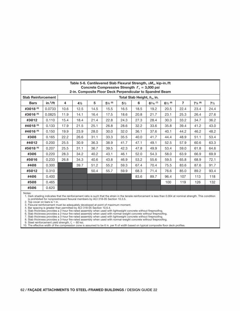
62 / FAÇADE ATTACHMENTS TO STEEL-FRAMED BUILDINGS / DESIGN GUIDE 22
Table 5-6. Cantilevered Slab Flexural Strength, φMn, kip-in./ft
Concrete Compressive Strength f´c � 3,000 psi
2-in. Composite Floor Deck Perpendicular to Spandrel Beam
Slab Reinforcement Total Slab Height, hs, in.
Bars in.2/ft 4 422 5 54 (5) 52 6 6x (7) 62 (6) 7 74 (8) 72
#3@18 (4) 0.0733 10.6 12.5 14.5 15.5 16.5 18.5 19.2 20.5 22.4 23.4 24.4
#3@16 (4) 0.0825 11.9 14.1 16.4 17.5 18.6 20.8 21.7 23.1 25.3 26.4 27.6
#3@12 0.110 15.4 18.4 21.4 22.8 24.3 27.3 28.4 30.3 33.2 34.7 36.2
#4@18 (4) 0.133 17.9 21.5 25.1 26.8 28.6 32.2 33.6 35.8 39.4 41.2 43.0
#4@16 (4) 0.150 19.9 23.9 28.0 30.0 32.0 36.1 37.6 40.1 44.2 46.2 48.2
#3@8 0.165 22.2 26.6 31.1 33.3 35.5 40.0 41.7 44.4 48.9 51.1 53.4
#4@12 0.200 25.5 30.9 36.3 38.9 41.7 47.1 49.1 52.5 57.9 60.6 63.3
#5@18 (4) 0.207 25.5 31.1 36.7 39.5 42.3 47.8 49.9 53.4 59.0 61.8 64.6
#3@6 0.220 28.3 34.2 40.2 43.1 46.1 52.0 54.3 58.0 63.9 66.9 69.9
#5@16 0.233 26.8 34.3 40.6 43.8 46.9 53.2 55.6 59.5 65.8 68.9 72.1
#4@8 0.300 39.7 51.2 55.2 59.3 67.4 70.4 75.5 83.6 87.6 91.7
#5@12 0.310 50.4 55.7 59.9 68.3 71.4 76.6 85.0 89.2 93.4
#4@6 0.400 83.6 89.7 96.4 107 113 118
#5@8 0.465 100 119 126 132
#5@6 0.620Notes:
1. Dark shading indicates that the reinforcement ratio is such that the strain in the tensile reinforcement is less than 0.004 at nominal strength. This condition is prohibited for nonprestressed flexural members by ACI 318-05 Section 10.3.5.
2. Top cover on bars is 1 in.3. Flexural reinforcement must be adequately developed at point of maximum moment.4. Bar spacing is greater than permitted by ACI 318-05 Section 10.6.4.5. Slab thickness provides a 2-hour fire-rated assembly when used with lightweight concrete without fireproofing.6. Slab thickness provides a 2-hour fire-rated assembly when used with normal-weight concrete without fireproofing.7. Slab thickness provides a 3-hour fire-rated assembly when used with lightweight concrete without fireproofing.8. Slab thickness provides a 3-hour fire-rated assembly when used with normal-weight concrete without fireproofing.9. Steel reinforcement yield strength, fy � 60 ksi.
10. The effective width of the compression zone is assumed to be 6 in. per ft of width based on typical composite floor deck profiles.
031-070_DG22_Ch05.indd 62 7/16/08 4:42:47 PM

DESIGN GUIDE 22 / FAÇADE ATTACHMENTS TO STEEL-FRAMED BUILDINGS / 63
Table 5-7. Cantilevered Slab Flexural Strength, φMn, kip-in./ft
Concrete Compressive Strength f´c � 4,000 psi
2-in. Composite Floor Deck Perpendicular to Spandrel Beam
Slab Reinforcement Total Slab Height, hs, in.
Bars in.2/ft 4 422 5 54 (5) 52 6 6x (7) 62 (6) 7 74 (8) 72
#3@18 (4) 0.0733 10.7 12.7 14.7 15.7 16.6 18.6 19.4 20.6 22.6 23.6 24.6
#3@16 (4) 0.0825 12.1 14.3 16.5 17.7 18.8 21.0 21.9 23.3 25.5 26.6 27.7
#3@12 0.110 15.7 18.7 21.7 23.2 24.7 27.6 28.7 30.6 33.6 35.1 36.5
#4@18 (4) 0.133 18.3 21.9 25.5 27.3 29.1 32.7 34.1 36.3 39.9 41.7 43.5
#4@16 (4) 0.150 20.5 24.5 28.6 30.6 32.6 36.7 38.2 40.7 44.8 46.8 48.8
#3@8 0.165 22.9 27.3 31.8 34.0 36.3 40.7 42.4 45.2 49.6 51.8 54.1
#4@12 0.200 26.5 31.9 37.3 40.0 42.7 48.1 50.1 53.5 58.9 61.6 64.3
#5@18 (4) 0.207 26.6 32.2 37.8 40.6 43.4 49.0 51.1 54.6 60.2 63.0 65.8
#3@6 0.220 29.6 35.5 41.4 44.4 47.4 53.3 55.5 59.3 65.2 68.2 71.1
#5@16 0.233 29.5 35.8 42.1 45.2 48.4 54.7 57.0 60.9 67.2 70.4 73.5
#4@8 0.300 37.2 45.5 53.6 57.6 61.7 69.8 72.8 77.9 86.0 90.0 94.1
#5@12 0.310 35.8 45.7 54.1 58.3 62.4 70.8 74.0 79.2 87.6 91.7 95.9
#4@6 0.400 54.2 68.3 73.7 79.1 89.9 93.9 101 112 117 122
#5@8 0.465 76.9 86.5 100 105 113 126 132 138
#5@6 0.620 134 159 168 177Notes:
1. Dark shading indicates that the reinforcement ratio is such that the strain in the tensile reinforcement is less than 0.004 at nominal strength. This condition is prohibited for nonprestressed flexural members by ACI 318-05 Section 10.3.5.
2. Top cover on bars is 1 in.3. Flexural reinforcement must be adequately developed at point of maximum moment.4. Bar spacing is greater than permitted by ACI 318-05 Section 10.6.4.5. Slab thickness provides a 2-hour fire-rated assembly when used with lightweight concrete without fireproofing.6. Slab thickness provides a 2-hour fire-rated assembly when used with normal-weight concrete without fireproofing.7. Slab thickness provides a 3-hour fire-rated assembly when used with lightweight concrete without fireproofing.8. Slab thickness provides a 3-hour fire-rated assembly when used with normal-weight concrete without fireproofing.9. Steel reinforcement yield strength, fy � 60 ksi.
10. The effective width of the compression zone is assumed to be 6 in. per ft of width based on typical composite floor deck profiles.
031-070_DG22_Ch05.indd 63 7/16/08 4:42:48 PM

64 / FAÇADE ATTACHMENTS TO STEEL-FRAMED BUILDINGS / DESIGN GUIDE 22
Table 5-8. Cantilevered Slab Flexural Strength, φMn, kip-in./ft
Concrete Compressive Strength f´c � 3,000 psi
3-in. Composite Floor Deck Perpendicular to Spandrel Beam
Slab Reinforcement Total Slab Height, hs, in.
Bars in.2/ft 5 522 6 64 (6) 62 7 7x (8) 72 (7) 8 84 (9) 82
#3@18 (5) 0.0733 14.5 16.5 18.5 19.5 20.5 22.4 23.2 24.4 26.4 27.4 28.4
#3@16 (5) 0.0825 16.4 18.6 20.8 22.0 23.1 25.3 26.2 27.6 29.8 30.9 32.0
#3@12 0.110 21.4 24.3 27.3 28.8 30.3 33.2 34.4 36.2 39.2 40.7 42.2
#4@18 (5) 0.133 25.1 28.6 32.2 34.0 35.8 39.4 40.8 43.0 46.6 48.4 50.2
#4@16 (5) 0.150 28.0 32.0 36.1 38.1 40.1 44.2 45.7 48.2 52.3 54.3 56.3
#3@8 0.165 31.1 35.5 40.0 42.2 44.4 48.9 50.6 53.4 57.8 60.0 62.3
#4@12 0.200 36.3 41.7 47.1 49.8 52.5 57.9 59.9 63.3 68.7 71.4 74.1
#5@18 (5) 0.207 36.7 42.3 47.8 50.6 53.4 59.0 61.1 64.6 70.2 73.0 75.8
#3@6 0.220 40.2 46.1 52.0 55.0 58.0 63.9 66.1 69.9 75.8 78.8 81.7
#5@16 0.233 40.6 46.9 53.2 56.4 59.5 65.8 68.2 72.1 78.4 81.5 84.7
#4@8 0.300 51.2 59.3 67.4 71.4 75.5 83.6 86.6 91.7 99.8 104 108
#5@12 0.310 50.4 59.9 68.3 72.4 76.6 85.0 88.1 93.4 102 106 110
#4@6 0.400 83.6 91.0 96.4 107 113 118 129 134 140
#5@8 0.465 100 119 125 132 145 151 158
#5@6 0.620 166 179 192Notes:
1. Dark shading indicates that the reinforcement ratio is such that the strain in the tensile reinforcement is less than 0.004 at nominal strength. This condition is prohibited for nonprestressed flexural members by ACI 318-05 Section 10.3.5.
2. Light shading indicates that reinforcement is less than minimum reinforcement ratio of 0.0018 required by ACI 318-05. This condition may be acceptable if the flexural strength exceeds the demand by more than one-third.
3. Top cover on bars is 1 in.4. Flexural reinforcement must be adequately developed at point of maximum moment.5. Bar spacing is greater than permitted by ACI 318-05 Section 10.6.4.6. Slab thickness provides a 2-hour fire-rated assembly when used with lightweight concrete without fireproofing.7. Slab thickness provides a 2-hour fire-rated assembly when used with normal-weight concrete without fireproofing.8. Slab thickness provides a 3-hour fire-rated assembly when used with lightweight concrete without fireproofing.9. Slab thickness provides a 3-hour fire-rated assembly when used with normal-weight concrete without fireproofing.
10. Steel reinforcement yield strength, fy � 60 ksi.11. The effective width of the compression zone is assumed to be 6 in. per ft of width based on typical composite floor deck profiles.
031-070_DG22_Ch05.indd 64 7/16/08 4:42:48 PM

DESIGN GUIDE 22 / FAÇADE ATTACHMENTS TO STEEL-FRAMED BUILDINGS / 65
Table 5-9. Cantilevered Slab Flexural Strength, φMn, kip-in./ft
Concrete Compressive Strength f´c � 4,000 psi
3-in. Composite Floor Deck Perpendicular to Spandrel Beam
Slab Reinforcement Total Slab Height, hs, in.
Bars in.2/ft 5 522 6 64 (6) 62 7 7x (8) 72 (7) 8 84 (9) 82
#3@18 (5) 0.0733 14.7 16.6 18.6 19.6 20.6 22.6 23.3 24.6 26.5 27.5 28.5
#3@16 (5) 0.0825 16.5 18.8 21.0 22.1 23.3 25.5 26.3 27.7 30.0 31.1 32.2
#3@12 0.110 21.7 24.7 27.6 29.1 30.6 33.6 34.7 36.5 39.5 41.0 42.5
#4@18 (5) 0.133 25.5 29.1 32.7 34.5 36.3 39.9 41.2 43.5 47.1 48.9 50.7
#4@16 (5) 0.150 28.6 32.6 36.7 38.7 40.7 44.8 46.3 48.8 52.9 54.9 56.9
#3@8 0.165 31.8 36.3 40.7 42.9 45.2 49.6 51.3 54.1 58.5 60.8 63.0
#4@12 0.200 37.3 42.7 48.1 50.8 53.5 58.9 60.9 64.3 69.7 72.4 75.1
#5@18 (5) 0.207 37.8 43.4 49.0 51.8 54.6 60.2 62.3 65.8 71.3 74.1 76.9
#3@6 0.220 41.4 47.4 53.3 56.3 59.3 65.2 67.4 71.1 77.1 80.1 83.0
#5@16 0.233 42.1 48.4 54.7 57.8 60.9 67.2 69.6 73.5 79.8 83.0 86.1
#4@8 0.300 53.6 61.7 69.8 73.8 77.9 86.0 89.0 94.1 102 106 110
#5@12 0.310 54.1 62.4 70.8 74.9 79.2 87.6 90.7 95.9 104 109 113
#4@6 0.400 68.3 79.1 89.9 95.3 101 112 116 122 133 139 144
#5@8 0.465 86.5 100 107 113 126 130 138 151 157 163
#5@6 0.620 134 159 166 177 193 202 210Notes:
1. Dark shading indicates that the reinforcement ratio is such that the strain in the tensile reinforcement is less than 0.004 at nominal strength. This condition is prohibited for nonprestressed flexural members by ACI 318-05 Section 10.3.5.
2. Light shading indicates that reinforcement is less than minimum reinforcement ratio of 0.0018 required by ACI 318-05. This condition may be acceptable if the flexural strength exceeds the demand by more than one-third.
3. Top cover on bars is 1 in.4. Flexural reinforcement must be adequately developed at point of maximum moment.5. Bar spacing is greater than permitted by ACI 318-05 Section 10.6.4.6. Slab thickness provides a 2-hour fire-rated assembly when used with lightweight concrete without fireproofing.7. Slab thickness provides a 2-hour fire-rated assembly when used with normal-weight concrete without fireproofing.8. Slab thickness provides a 3-hour fire-rated assembly when used with lightweight concrete without fireproofing.9. Slab thickness provides a 3-hour fire-rated assembly when used with normal-weight concrete without fireproofing.
10. Steel reinforcement yield strength, fy = 60 ksi.11. The effective width of the compression zone is assumed to be 6 in. per ft of width based on typical composite floor deck profiles.
031-070_DG22_Ch05.indd 65 7/16/08 4:42:48 PM

66 / FAÇADE ATTACHMENTS TO STEEL-FRAMED BUILDINGS / DESIGN GUIDE 22
Table 5-10. Minimum Thickness of Bent Plate, in.
Used as a Pour Stop for Normal-Weight Concrete
Slab Thickness, in.
Slab Overhang, in.
4 5 6 7 8 9 10 11 12 13 14 15 16 17 18
4 x x x x x x x x x x 4 4 4 c c
444 x x x x x x x x x x 4 4 4 c c
422 x x x x x x x x x x 4 4 4 c c
4ww x x x x x x x x x x 4 4 4 c c
5 x x x x x x x x x 4 4 4 c c c
544 x x x x x x x x x 4 4 4 c c c
522 x x x x x x x x x 4 4 4 c c c
5ww x x x x x x x x x 4 4 4 c c c
6 x x x x x x x x x 4 4 4 c c a
644 x x x x x x x x x 4 4 c c c a
622 x x x x x x x x 4 4 4 c c c a
6ww x x x x x x x x 4 4 4 c c c a
7 x x x x x x x x 4 4 4 c c c a
744 x x x x x x x x 4 4 4 c c a a
722 x x x x x x x x 4 4 4 c c a a
7ww x x x x x x x x 4 4 4 c c a a
8 x x x x x x x 4 4 4 c c c a a
844 x x x x x x x 4 4 4 c c c a a
822 x x x x x x x 4 4 4 c c c a a
8ww x x x x x x x 4 4 4 c c a a a
9 x x x x x x x 4 4 4 c c a a a
944 x x x x x x x 4 4 4 c c a a a
922 x x x x x x x 4 4 4 c c a a v
9ww x x x x x x x 4 4 c c c a a v
10 x x x x x x 4 4 4 c c c a a vNotes:1. Plate thickness is controlled by a maximum vertical deflection of 8 in. at the tip of the pour stop under the wet load of the concrete. If deflection is not a
concern, a thinner plate may provide adequate strength.2. Steel plate is ASTM A36 material.3. Concrete unit weight is 150 lb/ft3.4. Pour stops are checked for strength considering the wet load of the concrete, a 250-lb point load applied at the tip of the pour stop and a uniform
construction load of 20 psf. The point load and uniform construction load are not normally applied concurrently.5. Shading is provided for visual clarity.
031-070_DG22_Ch05.indd 66 7/16/08 4:42:49 PM

DESIGN GUIDE 22 / FAÇADE ATTACHMENTS TO STEEL-FRAMED BUILDINGS / 67
Table 5-11. Minimum Thickness of Bent Plate, in.
Used as a Pour Stop for Lightweight Concrete
Slab Thickness, in.
Slab Overhang, in.
4 5 6 7 8 9 10 11 12 13 14 15 16 17 18
4 x x x x x x x x x x x 4 4 4 c
444 x x x x x x x x x x x 4 4 4 c
422 x x x x x x x x x x 4 4 4 4 c
4ww x x x x x x x x x x 4 4 4 c c
5 x x x x x x x x x x 4 4 4 c c
544 x x x x x x x x x x 4 4 4 c c
522 x x x x x x x x x x 4 4 4 c c
5ww x x x x x x x x x x 4 4 4 c c
6 x x x x x x x x x 4 4 4 4 c c
644 x x x x x x x x x 4 4 4 c c c
622 x x x x x x x x x 4 4 4 c c c
6ww x x x x x x x x x 4 4 4 c c c
7 x x x x x x x x x 4 4 4 c c c
744 x x x x x x x x x 4 4 4 c c a
722 x x x x x x x x x 4 4 4 c c a
7ww x x x x x x x x 4 4 4 c c c a
8 x x x x x x x x 4 4 4 c c c a
844 x x x x x x x x 4 4 4 c c c a
822 x x x x x x x x 4 4 4 c c c a
8ww x x x x x x x x 4 4 4 c c a a
9 x x x x x x x x 4 4 4 c c a a
944 x x x x x x x x 4 4 c c c a a
922 x x x x x x x 4 4 4 c c c a a
9ww x x x x x x x 4 4 4 c c c a a
10 x x x x x x x 4 4 4 c c c a aNotes:1. Plate thickness is controlled by a maximum vertical deflection of 8 in. at the tip of the pour stop under the wet load of the concrete. If deflection is not a
concern, a thinner plate may provide adequate strength.2. Steel plate is ASTM A36 material. 3. Concrete unit weight is 115 lb/ft3.4. Pour stops are checked for strength considering the wet load of the concrete, a 250-lb point load applied at the tip of the pour stop, and a uniform con-
struction load of 20 psf. The point load and uniform construction load are not normally applied concurrently.5. Shading is provided for visual clarity.
031-070_DG22_Ch05.indd 67 7/16/08 4:42:49 PM

68 / FAÇADE ATTACHMENTS TO STEEL-FRAMED BUILDINGS / DESIGN GUIDE 22
Table 5-12. Headed Stud Tensile Strength, φNn, kips
4,000 psi Normal-Weight Concrete Slab Edges
Headed Stud
Diameter, in.
Embedment
Depth, in.
Total Slab Height, hs, in.
4 422 5 52 6 62 7 74 72 84
2
6 2.66 3.03 3.40 3.78 4.16 4.56 4.96 5.16 5.30 5.99
8 3.01 3.41 3.82 4.24 4.66 5.09 5.30 5.74 5.30 6.64
10 3.32 3.75 4.20 4.65 5.11 5.30 5.30 6.27 5.30 7.23
s
6 2.66 3.03 3.40 3.78 4.16 4.56 4.96 5.16 5.37 5.99
8 3.01 3.41 3.82 4.24 4.66 5.09 5.52 5.74 5.96 6.64
10 3.32 3.75 4.20 4.65 5.11 5.57 6.04 6.27 6.51 7.23
w
6 2.66 3.03 3.40 3.78 4.16 4.56 4.96 5.16 5.37 5.99
8 3.01 3.41 3.82 4.24 4.66 5.09 5.52 5.74 5.96 6.64
10 3.32 3.75 4.20 4.65 5.11 5.57 6.04 6.27 6.51 7.23Notes:1. Stud strengths are for single cast-in headed studs based on ACI 318-05 Appendix D. Refer to Section D.7 for interaction of tension and shear on headed
studs.2. In regions of moderate or high seismicity, values must be multiplied by 0.75 per Section D.3.3.3 of ACI 318-05 Appendix D.3. Stud material is assumed to have a tensile strength of 60 ksi.4. Calculations assume that the stud is centered at the mid-thickness of the slab, and that there are no free edges along the length of the slab within a dis-
tance of 1.5 times the embedment depth of the stud measured from the center of the stud.
Table 5-13. Headed Stud Shear Strength, φVn, kips
4,000 psi Normal-Weight Concrete Slab Edges
Headed Stud
Diameter, in.
Embedment
Depth, in.
Total Slab Height, hs, in.
4 422 5 52 6 62 7 74 72 84
2
6 1.07 1.28 1.50 1.73 1.97 2.22 2.49 2.62 2.76 3.18
8 1.07 1.28 1.50 1.73 1.97 2.22 2.49 2.62 2.76 3.18
10 1.07 1.28 1.50 1.73 1.97 2.22 2.49 2.62 2.76 3.18
s
6 1.20 1.43 1.68 1.94 2.21 2.49 2.78 2.93 3.08 3.56
8 1.20 1.43 1.68 1.94 2.21 2.49 2.78 2.93 3.08 3.56
10 1.20 1.43 1.68 1.94 2.21 2.49 2.78 2.93 3.08 3.56
w
6 1.31 1.57 1.84 2.12 2.42 2.72 3.04 3.21 3.38 3.89
8 1.31 1.57 1.84 2.12 2.42 2.72 3.04 3.21 3.38 3.89
10 1.31 1.57 1.84 2.12 2.42 2.72 3.04 3.21 3.38 3.89Notes:1. Stud strengths are for single cast-in headed studs welded to steel attachments with a a-in. minimum thickness based on ACI 318-05 Appendix D. Refer to
Section D.7 for interaction of tension and shear on headed studs.2. In regions of moderate or high seismicity, values must be multiplied by 0.75 per Section D.3.3.3 of ACI 318-05 Appendix D.3. Stud material is assumed to have a tensile strength of 60 ksi.4. Calculations assume that the stud is centered at the mid-thickness of the slab, and that there are no free edges along the length of the slab within a dis-
tance of 1.5 times the embedment depth of the stud measured from the center of the stud.
031-070_DG22_Ch05.indd 68 7/16/08 4:42:50 PM
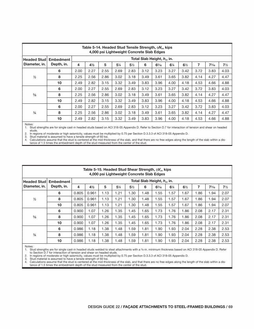
DESIGN GUIDE 22 / FAÇADE ATTACHMENTS TO STEEL-FRAMED BUILDINGS / 69
Table 5-14. Headed Stud Tensile Strength, φNn, kips
4,000 psi Lightweight Concrete Slab Edges
Headed Stud
Diameter, in.
Embedment
Depth, in.
Total Slab Height, hs, in.
4 422 5 54 52 6 6x 64 62 7 7x 72
2
6 2.00 2.27 2.55 2.69 2.83 3.12 3.23 3.27 3.42 3.72 3.83 4.03
8 2.25 2.56 2.86 3.02 3.18 3.49 3.61 3.65 3.82 4.14 4.27 4.47
10 2.49 2.82 3.15 3.32 3.49 3.83 3.96 4.00 4.18 4.53 4.66 4.88
s
6 2.00 2.27 2.55 2.69 2.83 3.12 3.23 3.27 3.42 3.72 3.83 4.03
8 2.25 2.56 2.86 3.02 3.18 3.49 3.61 3.65 3.82 4.14 4.27 4.47
10 2.49 2.82 3.15 3.32 3.49 3.83 3.96 4.00 4.18 4.53 4.66 4.88
w
6 2.00 2.27 2.55 2.69 2.83 3.12 3.23 3.27 3.42 3.72 3.83 4.03
8 2.25 2.56 2.86 3.02 3.18 3.49 3.61 3.65 3.82 4.14 4.27 4.47
10 2.49 2.82 3.15 3.32 3.49 3.83 3.96 4.00 4.18 4.53 4.66 4.88Notes:1. Stud strengths are for single cast-in headed studs based on ACI 318-05 Appendix D. Refer to Section D.7 for interaction of tension and shear on headed
studs.2. In regions of moderate or high seismicity, values must be multiplied by 0.75 per Section D.3.3.3 of ACI 318-05 Appendix D.3. Stud material is assumed to have a tensile strength of 60 ksi.4. Calculations assume that the stud is centered at the mid-thickness of the slab, and that there are no free edges along the length of the slab within a dis-
tance of 1.5 times the embedment depth of the stud measured from the center of the stud.
Table 5-15. Headed Stud Shear Strength, φVn, kips
4,000 psi Lightweight Concrete Slab Edges
Headed Stud
Diameter, in.
Embedment
Depth, in.
Total Slab Height, hs, in.
4 422 5 54 52 6 6x 64 62 7 7x 72
2
6 0.805 0.961 1.13 1.21 1.30 1.48 1.55 1.57 1.67 1.86 1.94 2.07
8 0.805 0.961 1.13 1.21 1.30 1.48 1.55 1.57 1.67 1.86 1.94 2.07
10 0.805 0.961 1.13 1.21 1.30 1.48 1.55 1.57 1.67 1.86 1.94 2.07
s
6 0.900 1.07 1.26 1.35 1.45 1.65 1.73 1.76 1.86 2.08 2.17 2.31
8 0.900 1.07 1.26 1.35 1.45 1.65 1.73 1.76 1.86 2.08 2.17 2.31
10 0.900 1.07 1.26 1.35 1.45 1.65 1.73 1.76 1.86 2.08 2.17 2.31
w
6 0.986 1.18 1.38 1.48 1.59 1.81 1.90 1.93 2.04 2.28 2.38 2.53
8 0.986 1.18 1.38 1.48 1.59 1.81 1.90 1.93 2.04 2.28 2.38 2.53
10 0.986 1.18 1.38 1.48 1.59 1.81 1.90 1.93 2.04 2.28 2.38 2.53Notes:1. Stud strengths are for single cast-in headed studs welded to steel attachments with a a-in. minimum thickness based on ACI 318-05 Appendix D. Refer
to Section D.7 for interaction of tension and shear on headed studs.2. In regions of moderate or high seismicity, values must be multiplied by 0.75 per Section D.3.3.3 of ACI 318-05 Appendix D.3. Stud material is assumed to have a tensile strength of 60 ksi.4. Calculations assume that the stud is centered at the mid-thickness of the slab, and that there are no free edges along the length of the slab within a dis-
tance of 1.5 times the embedment depth of the stud measured from the center of the stud.
031-070_DG22_Ch05.indd 69 7/16/08 4:42:50 PM

70 / FAÇADE ATTACHMENTS TO STEEL-FRAMED BUILDINGS / DESIGN GUIDE 22
031-070_DG22_Ch05.indd 70 7/16/08 4:42:51 PM
DESIGN GUIDE 22 / FAÇADE ATTACHMENTS TO STEEL-FRAMED BUILDINGS / 71
Chapter 6 Design of Steel Spandrel Beams
6.1 GENERAL DESIGN CONSIDERATIONS
The design of a spandrel beam involves more than just se-lecting a wide-fl ange shape that meets fl exural strength and stiffness criteria. Flexural strength and stiffness are primary, but only two of potentially many other factors that must be considered, some of which are detailing requirements infl u-enced by architectural and mechanical design decisions.
Common design considerations include, but may not be limited to, the following:
Flexural strength—Is the spandrel beam composite or non-composite? Is it part of a moment frame? Is weak-axis bend-ing from façade forces a design consideration due to large fl oor openings adjacent to the spandrel beam?
Flexural stiffness—What are the superimposed dead- and live-load defl ection requirements? What are the façade de-fl ection requirements? Do fl oor vibration considerations af-fect the design? Is long-term defl ection from creep an issue in composite sections? Are lateral defl ections from façade forces a design consideration due to large fl oor openings adjacent to the spandrel beam?
Connections to columns—Are they simple shear connections or are the spandrel beams part of a moment frame? Are they typical in confi guration, or is the web of the spandrel beam offset from the column centerline enough that nonstandard connections are necessary? Are horizontal forces a design consideration? Does the connection geometry interfere with slab edge detailing requirements?
Torsion—Is torsion a design consideration? Is the torsion resolved at the columns, or with roll beams or kickers? Does the design address rotation of the spandrel beam, which results in rotation and projected vertical displacement of façade supports that are eccentric to the spandrel beam?
Depth—Are there depth requirements or limitations? Does the depth interfere with the window heads, shade pockets, or other features unique to the building perimeter conditions? Should any of the spandrel beams be deeper than structur-ally required to facilitate window head anchorage or other façade connections? Should a constant depth be used for the spandrel beams throughout the project for a standardized architectural or façade connection detail?
Flange width and thickness—Are there minimum or maxi-mum fl ange dimensions required for the slab edge or façade
attachment details? Is there enough width to allow for edge plates, headed studs (including the size of the installation ferrule), deck bearing, and other items? Is the fl ange thick enough to allow headed studs to be placed off the centerline, if necessary? Should the range of fl ange widths be minimized for the spandrel beams throughout the project?
Location—Is the centerline of the spandrel beam on the centerline of the columns or is it offset? Is the spandrel beam suffi ciently close to the slab edge to minimize eccentricities from the façade? Is the spandrel beam suffi ciently set back from the slab edge to allow for fi re-safi ng, fi reproofi ng, and façade elements to pass by with appropriate clearances for installation?
Fabrication and erection—Does the spandrel beam design appropriately account for fabrication and erection? Does the detail appropriately balance member weight with simplicity and effi ciency of fabrication and erection?
Value engineering—Will the spandrel beam detail be easy to change if there is a change to the façade system as a re-sult of value engineering? It is the author’s experience that less-than-ideal spandrel beam details often result from last-minute (but necessary) cost reductions achieved through changing the façade system. Although designers cannot predict change with certainty, it is worth considering if there is potential for change and what may be the likely alternative façade systems.
Some of these considerations are unique to the spandrel beam, and many require the designer to evaluate the spandrel beam detail more closely than other project details. Some may also require give and take for coordination with archi-tectural fi nishes and other building systems.
6.2 DESIGN OF THE SPANDREL BEAM FOR VERTICAL LOADS
For spandrel beams supporting façade loads, the design is of-ten controlled by defl ections unless the spandrel beam is part of a moment frame. Other AISC publications, such as the Specifi cation for Structural Steel Buildings (AISC, 2005b), hereafter referred to as the AISC Specifi cation, provide guid-ance on the strength design of composite and noncomposite steel beams. However, the following are potential issues the designer should be aware of when evaluating the strength of spandrel beams for vertical loads:
071-114_DG22_Ch06.indd 71 7/16/08 4:45:54 PM

72 / FAÇADE ATTACHMENTS TO STEEL-FRAMED BUILDINGS / DESIGN GUIDE 22
• Do slab edge closure plates and/or other façade attach-ment elements in the slab preclude proper spacing of headed studs?
• Do slab depressions or openings preclude designing the beam as a composite beam?
• Are there torsional effects or fl exural effects from hori-zontal forces that must be combined with fl exural effects from vertical loads?
• Are there local strength issues from façade attachments, such as local web yielding or fl ange bending?
Defl ection and movement limitations for most façade sys-tems are such that the stiffness, not strength, will usually control the size of the spandrel beam. The defl ection crite-ria for spandrel beams may not be simply a function of the span length as is often the case for fl oor beams. The appli-cable defl ection or movement limitation(s) may be absolute-magnitude value(s), not a function of the span, for certain façade movement joint designs, such as horizontal soft joints in masonry veneers or precast-concrete panels.
The allowable spandrel beam vertical defl ection is the por-tion of the allowable joint movement reserved for the struc-tural defl ection, less any signifi cant defl ections due to the fl exibility of secondary support elements, such as hangers, relieving angles, and brackets. In addition, any rotation of the spandrel beam will translate into vertical and horizontal movements at the joint, as illustrated in Figure 6-1, further limiting the allowable vertical defl ections.
After determining the allowable vertical defl ections of the spandrel beam, the designer should consider when the spandrel beam defl ections occur relative to the construction of the façade system. At least 50 percent of the fl oor live
load defl ections must be included in the design of the façade movement joints. However, signifi cant superimposed fl oor dead loads may also require consideration. For example, the spandrel beam defl ections due to the installation of stone or brick veneer will affect the design of the back-up anchorage and movement joints. For another example, the controlling defl ection criteria for a spandrel beam supporting a brick ve-neer system may be the allowable defl ection from the sum of all loads applied after the erection of the back-up, includ-ing superimposed dead and live loads, plus the weight of the veneer itself. These loads contribute to defl ections that close the horizontal movement joint in the veneer.
Examples of calculated defl ections for spandrel beams supporting four different façade systems are provided in Tables 6-1 through 6-4, which cover brick veneer cladding with 8-in. concrete masonry unit (CMU) back-up, brick ve-neer cladding with 6-in. metal stud back-up, 6-in. precast-concrete panel cladding, and aluminum curtain wall clad-ding, respectively. For each system, the table provides three spandrel beam sizes: the size if there were no defl ection lim-its; the size if the defl ections limits were similar to those used for typical fl oor beams, with a net total defl ection less than L/240 and live load defl ection less than L/360; and the size required to meet specifi c defl ection limits that are typi-cal for the particular façade system. In all four examples, the spandrel beam size is controlled by façade defl ection limits with the most signifi cant effect being for the brick veneer example, which has the most stringent limitations in these examples. Note that the same size spandrel beam is needed for both the CMU back-up and metal stud back-up systems despite the block being heavier. The controlling criterion is the allowable defl ection for the joint, and both systems have the same load for this criterion.
Fig. 6-1. Impact of angular rotation of spandrel beam on façade movement.
071-114_DG22_Ch06.indd 72 7/16/08 4:45:55 PM

DESIGN GUIDE 22 / FAÇADE ATTACHMENTS TO STEEL-FRAMED BUILDINGS / 73
Table 6-1. Example Composite Spandrel Beam Deflections
Brick Veneer Cladding 8-in. CMU Back-up (Grouted 32 in. o.c.)
Deflection Restriction
no δδ
restriction
δNTD = L/240 = 1½ in.
δLL = L/360 = 1 in.δSIDL+LL = x in.
Required spandrel size W16x26 W16x31 W21x62
Pre-composite defl ection, in. 0.606 0.494 0.154
Defl ection due to back-up, in. 0.424 0.356 0.165
Defl ection due to brick, in. 0.339 0.284 0.132
Defl ection due to SIDL, in. 0.0389 0.0326 0.015
Defl ection due to LL, in. 0.389 0.326 0.151
Camber, in. none none none
Net Total Defl ection (NTD), in. 1.80 1.49 0.617
δSIDL+LL, in. 0.429 0.359 0.166
Mu/φbMn 0.934 0.774 0.421
Notes:
1. Superimposed Dead Load (SIDL) is the portion of the dead load applied after the concrete slab has cured, excluding cladding loads.
2. LL is the Live Load.3. The Net Total Deflection (NTD) is the sum of the individual
deflections minus the camber.4. Camber is upward (opposite in direction to the in-service
deflections).
Design Parameters:
Beam span 30 ftSIDL 10 psfLL 100 psfFloor-to-floor height 12 ftFloor tributary width 5½ ftSlab construction 6¼-in. lightweight concrete on 3-in. deck Brick veneer weight 40 psfCMU weight 50 psf
Table 6-2. Example Composite Spandrel Beam Deflections
Brick Veneer Cladding with 6-in. Metal Stud Back-up (16-in. Spacing)
Deflection Restriction
no δδ
restriction
δNTD = L/240 = 1½ in.
δLL = L/360 = 1 in.δSIDL+LL = x in.
Required spandrel size W12x19 W16x26 W21x62
Pre-composite defl ection, in. 1.37 0.606 0.154
Defl ection due to back-up, in. 0.113 0.081 0.0297
Defl ection due to brick, in. 0.501 0.359 0.132
Defl ection due to SIDL, in. 0.0574 0.0411 0.0151
Defl ection due to LL, in. 0.574 0.411 0.151
Camber, in. None none none
Net Total Defl ection (NTD), in. 2.62 1.50 0.482
δSIDL+LL, in. 1.13 0.811 0.166
Mu/φbMn 0.937 0.754 0.327
Notes:
1. Superimposed Dead Load (SIDL) is the portion of the dead load applied after the concrete slab has cured, excluding cladding loads.
2. LL is the Live Load.3. The Net Total Deflection (NTD) is the sum of the individual
deflections minus the camber.4. Camber is upward (opposite in direction to the in-service
deflections).
Design Parameters:
Beam span 30 ftSIDL 10 psfLL 100 psfFloor-to-floor height 12 ftFloor tributary width 5½ ftSlab construction 6¼-in. lightweight concrete on 3-in. deckBrick veneer weight 40 psfMetal stud weight 9 psf
071-114_DG22_Ch06.indd 73 7/17/08 11:41:15 AM

74 / FAÇADE ATTACHMENTS TO STEEL-FRAMED BUILDINGS / DESIGN GUIDE 22
Table 6-3. Example Composite Spandrel Beam Deflections
6-in. Precast-Concrete Panel Cladding
Deflection Restriction
no δδ
restriction
δNTD = L/240 = 1½ in.
δLL = L/360 = 1 in.δSIDL+LL = a in.
Required spandrel size W14x22 W16x26 W18x40
Pre-composite defl ection, in. 0.903 0.606 0.312
Defl ection due to precast, in. 0.735 0.533 0.457
Defl ection due to SIDL, in. 0.0449 0.0326 0.0297
Defl ection due to LL, in. 0.449 0.326 0.297
Camber, in. none none none
Net Total Defl ection (NTD), in. 2.13 1.50 1.08
δSIDL+LL, in. 1.23 0.892 0.307
Mu/φbMn 0.930 0.736 0.621
Notes:
1. Superimposed Dead Load (SIDL) is the portion of the dead load applied after the concrete slab has cured, excluding cladding loads.
2. LL is the Live Load.3. The Net Total Deflection (NTD) is the sum of the individual
deflections minus the camber.4. Camber is upward (opposite in direction to the in-service
deflections).
Design Parameters:
Beam span 30 ftSIDL 10 psfLL 100 psfFloor-to-floor height 12 ftFloor tributary width 5½ ftSlab construction 6¼-in. lightweight concrete
on 3-in. deckPrecast weight 75 psf
Table 6-4. Example Composite Spandrel Beam Deflections
Aluminum Curtain Wall Cladding
Deflection Restriction
no δδ
restriction
δNTD = L/240 = 1½ in.
δLL = L/360 = 1 in.δCW+SIDL+LL = w in.
Required spandrel size W12x14 W16x26 W16x26
Pre-composite defl ection, in. 1.97 0.606 0.606
Defl ection due to curtain wall, in. 0.243 0.151 0.151
Defl ection due to SIDL, in. 0.0744 0.0462 0.0462
Defl ection due to LL, in. 0.744 0.462 0.462
Camber, in. 1.25 none none
Net Total Defl ection (NTD), in. 1.78 1.27 1.27
δcw+SIDL+LL, in. 1.06 0.659 0.659
Mu/φbMn 0.930 0.633 0.633Notes:
1. Superimposed Dead Load (SIDL) is the portion of the dead load applied after the concrete slab has cured, excluding cladding loads.
2. LL is the Live Load.3. The Net Total Deflection (NTD) is the sum of the individual
deflections minus the camber.4. Camber is upward (opposite in direction to the in-service
deflections).
Design Parameters:
Beam span 30 ftSIDL 10 psfLL 100 psfFloor-to-floor height 12 ftFloor tributary width 5½ ftSlab construction 6¼-in. lightweight concrete
on 3-in. deckCurtain wall weight 15 psf
071-114_DG22_Ch06.indd 74 7/16/08 4:45:55 PM

DESIGN GUIDE 22 / FAÇADE ATTACHMENTS TO STEEL-FRAMED BUILDINGS / 75
For these typical examples, camber in the spandrel beam does not help reduce the size, except for the relatively light aluminum curtain wall system. Any camber in the spandrel beam also places greater tolerance demands on the façade attachments to account for camber tolerances and the un-certainty in the prediction of how much camber will actu-ally come out after loading. Hence, there is wisdom in the common recommendation that camber should be avoided in spandrel beams.
As the examples in Tables 6-1 through 6-4 show, keeping the defl ections of the spandrel beam small that occur after the sealant is installed in masonry veneers can lead to deep and heavy sections. This may impact the project when the overall steel tonnage of the building is a critical design ob-jective. Communication between the engineer and architect is necessary to be sure the architect understands the impact the joint size has on the spandrel. Rather than determine the incremental defl ections due to the live loads, superimposed dead loads, and brick loads, some engineers design spandrel beams supporting brick veneer walls for the lesser of L/600 or 0.31 in. as required by ACI 530-05 (ACI, 2005). If the architect’s joint size is not consistent with the net defl ection after the sealant is in place, the sealant’s allowable repeti-tive strains may be exceeded as the brick’s volume changes over time. This may lead to bulging and protruding sealant in the soft joint below the shelf angle and may shorten the interval at which the sealant needs to be replaced. The owner and design team should decide on a strategy that balances
the up-front costs of additional steel tonnage against future maintenance costs.
6.3 DESIGN OF THE SPANDREL BEAM FOR TORSION
Some façade details and conditions tend to induce torsion on the spandrel beam, as illustrated in Figure 6-2. The rotational fl exibility of a wide-fl ange shape when twisted about its lon-gitudinal axis is such that torsion must be eliminated, if pos-sible, or limited by providing torsional restraints along the length of the spandrel beam. Restraint is provided by kickers, fl oor beams or roll beams, and/or connections to columns.
If the location of restraints along the spandrel beam can be coordinated with the location of the applied façade loads that cause the torsion, torsion in the spandrel beam can be avoided altogether. However, for some façade systems, especially those designed by the façade contractor, the designer cannot be certain of the locations of the applied loads when designing the spandrel beams. Therefore, it is often prudent to consider the effect of eccentric façade loads applied between torsional restraints when selecting the spandrel beams. Economical designs are achieved when the spacing of restraint locations is between 10 and 15 ft on center, even if the spandrel beam is required to be slightly heavier for torsion applied between restraints.
Concrete slabs that are anchored to the spandrel beam top fl ange with shear stud connectors are an additional source
Fig. 6-2. Example detail that induces torsion on spandrel beam.
071-114_DG22_Ch06.indd 75 7/16/08 4:45:55 PM

76 / FAÇADE ATTACHMENTS TO STEEL-FRAMED BUILDINGS / DESIGN GUIDE 22
of torsional restraint for spandrel beams. The amount of ro-tational restraint offered by the slab depends on the fl exural rigidity and strength of the slab. Strength and rigidity may not be adequate when the slab is composed of composite deck and the deck runs parallel with the spandrel beam, in which case it is common to not rely on the fl exural strength of the composite slab as a sole means of restraining torsion. Even in this case, however, the designer can use the slab to reduce the rotation of the beam because the slab restrains lateral movement of the top fl ange. When the top fl ange is restrained from lateral movement in the plane of the slab, the center of rotation of the beam is at the top fl ange, as il-lustrated in Figure 6-3.
References such as AISC Design Guide No. 9, Torsional Analysis of Structural Steel Members (Seaburg and Carter, 1997), and Salmon and Johnson (1996) provide guidance on the design of wide-fl ange beams subjected to torsion. How-ever, few references address the case of a beam with the top fl ange braced against translation by a deck or slab and sub-jected to torsion, which is the case for most spandrel beam conditions. The rotational response in this case is consider-ably different from that of a bare beam.
A designer may be inclined to treat the spandrel beam as a bare steel member, ignoring the slab entirely. While this generally will be conservative with respect to the total rota-tion, it does not consider that the beam rotates about the top fl ange. If the cladding attachment is at or below the center of gravity of the beam, the distance to the point of rotation, or radius, will be increased, as will the translational defl ections at the cladding attachment.
The designer conservatively can account for the effects of the braced top fl ange by using the rotation obtained by the method presented in Seaburg and Carter (1997), but with the idealized rotation applied about the top fl ange of the span-drel beam when computing translation defl ections of clad-ding supports.
Another option is to use the “fl exural analogy” method presented by Salmon and Johnson (1996) for the analysis of steel beams in torsion. This method converts the applied twist into a force couple acting on the top and bottom fl anges of the beam. The fl anges are then considered as simply sup-ported beams spanning between the torsional restraints in the real beam. As illustrated in Figure 6-4, the defl ections are calculated with the bottom fl ange defl ecting in one direc-tion and the top fl ange defl ecting in the opposite direction, and converting the result into an equivalent rotation. This approach can also account for the braced top fl ange by rec-ognizing that the top fl ange does not translate and the beam rotates about the top. The bottom fl ange defl ection is calcu-lated and the rotation is determined using the full depth of the beam as the radius.
Appendix A presents a study that compares the methods just described to fi nite element models to assess their ap-propriateness for practical design. The study indicates that both approximate methods predict bottom fl ange defl ections greater than those determined by fi nite element modeling. Of the two methods, the fl exural analogy provides the most accurate prediction of the beam bottom fl ange lateral dis-placement for torsional spans in the range of 10 ft. At spans in the 20- to 30-ft range, the unrestrained rotation calculated using the method presented in Seaburg and Carter (1997), but applied relative to the top fl ange, provides a better ap-proximation. See Appendix A for a discussion of the model-ing procedure and a comparison of results.
A common condition in which the designer must consider torsion along a considerable length of spandrel beam is at fl oor openings along exterior walls, such as stairways, as illustrated in Figure 6-5. At these conditions, the spandrel beam often must be designed for weak-axis bending due to horizontal façade forces in addition to vertical loads and tor-sion over a signifi cant length. It is generally uneconomical to increase the size of the spandrel beam for this loading
Fig. 6-3. Effects of slab fl exure on torsion in spandrel beam.
071-114_DG22_Ch06.indd 76 7/16/08 4:45:56 PM

DESIGN GUIDE 22 / FAÇADE ATTACHMENTS TO STEEL-FRAMED BUILDINGS / 77
Fig. 6-4. Illustration of fl exural analogy.
Fig. 6-5. Torsion in spandrel beam at stair opening.
condition, and some alternative details are illustrated in Fig-ure 6-6. In each case, the framing at the opening must re-strain the torsion at each end of the opening.
In the fi rst option (Figure 6-6a), a closed cross-section is created from the wide-fl ange spandrel beam by adding a ver-tical plate connecting the tips of the top and bottom fl anges over all or some portion(s) of the length between points of restraint. This will signifi cantly increase the rotational stiff-ness, and preserve much of the typical spandrel beam detail. The rest of the span outside the width of the opening can continue with the typical spandrel beam section.
In the second option, the wide-fl ange shape is replaced with a hollow structural section (HSS). This also will sig-nifi cantly increase the rotational stiffness, but may require the designer to alter other parts of the typical spandrel beam detail, such as stiffeners, façade attachments, and connec-tions of other framing to the spandrel beam.
In the third option, a closed shape is welded to the top (or bottom) of the wide-fl ange spandrel beam. This also will sig-nifi cantly increase the rotational stiffness, and preserve the typical spandrel beam detail, but may complicate fi reproof-ing and the connection to the column.
071-114_DG22_Ch06.indd 77 7/16/08 4:45:56 PM

78 / FAÇADE ATTACHMENTS TO STEEL-FRAMED BUILDINGS / DESIGN GUIDE 22
Examples 6.1, 6.2, 6.3, and 6.4 present the design of roof spandrel beams considering the effects of torsion due to cladding loads. Examples 6.5 and 6.6 examine the design of fl oor spandrel beams for cladding loads and also con-sider torsional effects. These examples illustrate strategies to restrain the twist in the spandrel beam and minimize the torsional stresses and rotations, thus minimizing the weight of the spandrel beam. Note that many of the torsional prop-erties used in the examples are taken from AISC Design Guide No. 9, Torsional Analysis of Structural Steel Members (Seaburg and Carter, 1997).
Detailed calculations are provided for all sources of rota-tion and defl ection that can contribute to the movement of the façade. These calculations show that not all sources of fl exibility are signifi cant, and many need not be considered in a routine design. Note, however, that it is important to consider all signifi cant sources of fl exibility.
Example 6.1—Roof Spandrel Beam with Eccentric Curtain Wall Load
For the wide-fl ange roof spandrel beam illustrated in Figures 6-7 and 6-8, evaluate the spandrel beam for strength and cal-culate the defl ection for the following conditions:
Condition A. A W18×35 spandrel beam ignoring the effects of torsion.
Condition B. A W21×50 spandrel beam considering the ef-fects of torsion, with the spandrel beam fl exurally and tor-sionally pinned at the supporting columns.
The curtain wall system requires that the maximum span-drel beam vertical defl ection must be limited to 0.90 in. at the center of the span. (This limit corresponds to span/400; note that the appropriate limit will vary based on the condi-tions and systems used.) Use ASTM A992 material for the W-shape (Fy = 50 ksi).
Given:For this example, assume that the controlling strength load combination is 1.2D + 1.6S + 0.8W (D + S + W for defl ection).
The spandrel beam span, L = 30 ft. The story height, h = 14 ft. The architect has set the edge angle face at 6 in. from the centerline of the spandrel beam; thus, leod = 6 in. The roof deck height, hd = 3 in., and it spans sdeck = 10 ft to the fi rst interior beam parallel to the spandrel beam. The deck braces the beam top fl ange laterally and also provides in-plane re-sistance to the wind load.
The roof dead load, wdead = 15 psf. The roof snow load, wsnow = 30 psf. The spandrel beam also supports two stories of curtain wall cladding (wcurt = 15 psf) attached with six façade attachments at spacing, sc = 5 ft, centered along the length of the spandrel beam. These loads are illustrated in Figure 6-9. The eccentricity between the CG of the curtain wall and the centerline of the spandrel beam, ecw = 9 in. Assume the curtain wall attachment width, bcw = 2 in. The cladding is exposed to a “components and cladding” wind suction, pw = 30 psf (acting away from the building). The tributary height for wind load is one story.
Fig. 6-6. Alternative details for spandrel beams subjected to signifi cant torsion and/or weak-axis forces.
071-114_DG22_Ch06.indd 78 7/16/08 4:45:57 PM
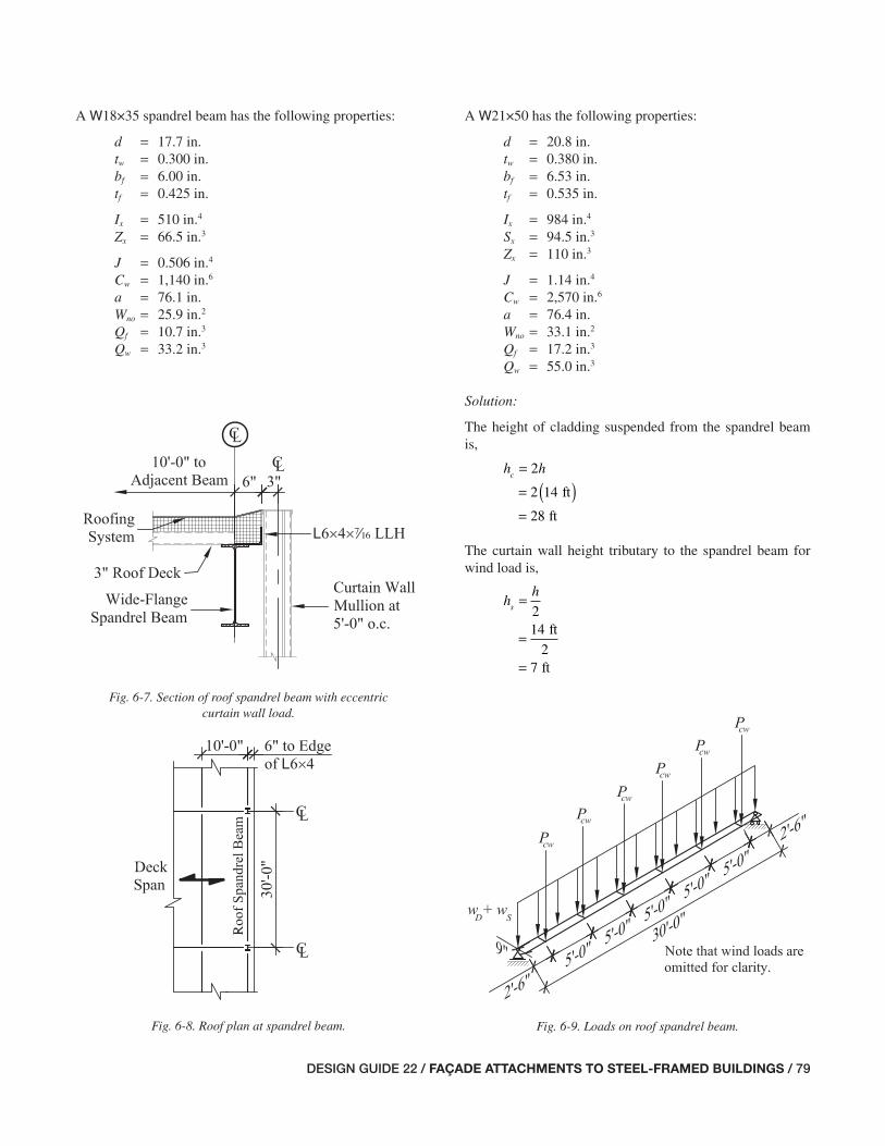
DESIGN GUIDE 22 / FAÇADE ATTACHMENTS TO STEEL-FRAMED BUILDINGS / 79
Fig. 6-7. Section of roof spandrel beam with eccentric curtain wall load.
Fig. 6-8. Roof plan at spandrel beam. Fig. 6-9. Loads on roof spandrel beam.
A W18×35 spandrel beam has the following properties:
d = 17.7 in. tw = 0.300 in. bf = 6.00 in. tf = 0.425 in.
Ix = 510 in.4
Zx = 66.5 in.3
J = 0.506 in.4
Cw = 1,140 in.6
a = 76.1 in. Wno = 25.9 in.2
Qf = 10.7 in.3
Qw = 33.2 in.3
A W21×50 has the following properties:
d = 20.8 in. tw = 0.380 in. bf = 6.53 in. tf = 0.535 in.
Ix = 984 in.4
Sx = 94.5 in.3
Zx = 110 in.3
J = 1.14 in.4
Cw = 2,570 in.6
a = 76.4 in. Wno = 33.1 in.2
Qf = 17.2 in.3
Qw = 55.0 in.3
Solution:
The height of cladding suspended from the spandrel beam is,
h hc
=
= ( )=
2
2 14
28
ft
ft
The curtain wall height tributary to the spandrel beam for wind load is,
hh
s=
=
=
214
27
ft
ft
071-114_DG22_Ch06.indd 79 7/16/08 4:45:57 PM
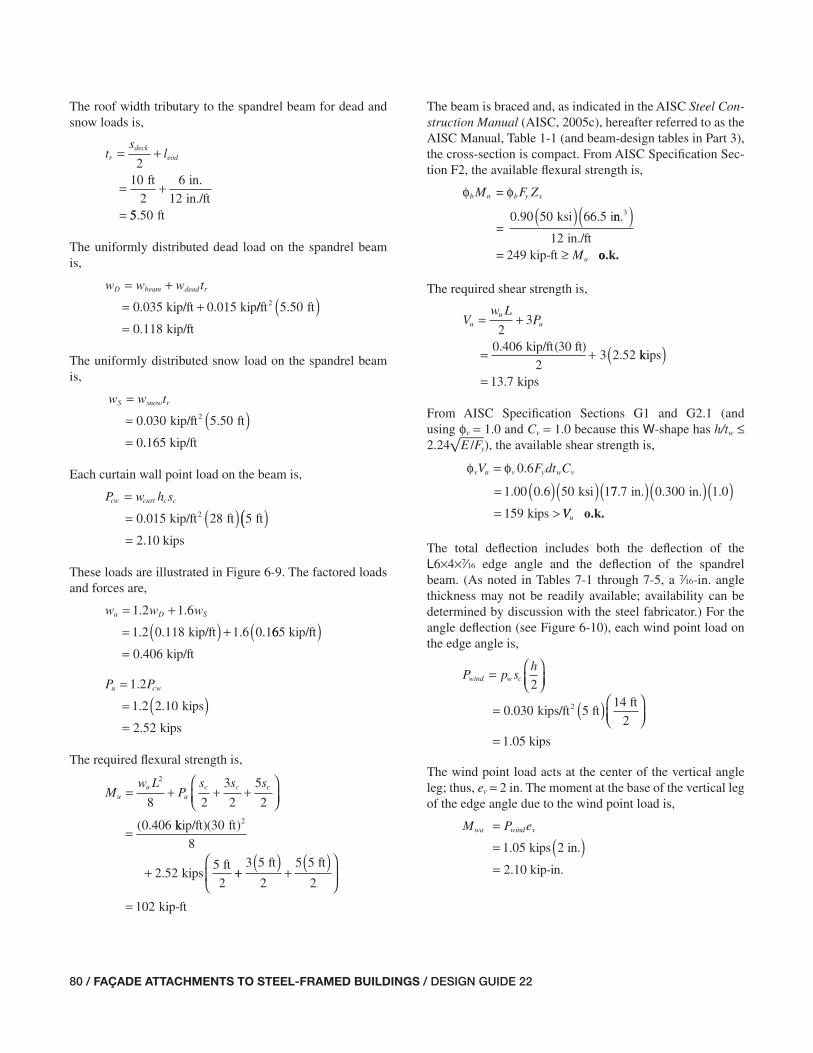
80 / FAÇADE ATTACHMENTS TO STEEL-FRAMED BUILDINGS / DESIGN GUIDE 22
The roof width tributary to the spandrel beam for dead and snow loads is,
ts
lrdeck
eod= +
= +
=
210
2
6
12
ft in.
in./ft55 50. ft
The uniformly distributed dead load on the spandrel beam is,
w w w tD beam dead r= +
= +kip/ft kip0 035 0 015. . //ft ft
kip/ft
2 5 50
0 118
.
.
( )=
The uniformly distributed snow load on the spandrel beam is,
w w tS snow r=
= ( )=
kip/ft ft20 030 5 50
0
. .
..165 kip/ft
Each curtain wall point load on the beam is,
P w h scw curt c c=
= ( )kip/ft ft ft20 015 28 5. (( )= 2.10 kips
These loads are illustrated in Figure 6-9. The factored loads and forces are,
w w wu D S= +
= ( ) +
1 2 1 6
1 2 0 118 1 6 0 1
. .
. . . .kip/ft 665
0 406
kip/ft
kip/ft
( )= .
P Pu cw=
= ( )=
1 2
1 2 2 10
2 52
.
. .
.
kips
kips
The required fl exural strength is,
Mw L
Ps s s
uu
uc c c= + + +
⎛⎝⎜
⎞⎠⎟
=
2
8 2
3
2
5
2
0 406( . kkip/ft ft
kipsft
)( )
.
30
8
2 525
2
2
+ ++( )
+( )⎛
⎝⎜
⎞
⎠⎟
=
3 5
2
5 5
2
102
ft ft
kip-ft
The beam is braced and, as indicated in the AISC Steel Con-struction Manual (AISC, 2005c), hereafter referred to as the AISC Manual, Table 1-1 (and beam-design tables in Part 3), the cross-section is compact. From AISC Specifi cation Sec-tion F2, the available fl exural strength is,
φ φb n b y xM F Z=
=0.90 ksi i50 66 5( ) . nn.
in./ft= 249 kip-ft
3( )≥
12Mu oo.k.
The required shear strength is,
Vw L
Puu
u= +
= +
23
0 406
23 2 52
kip/ft(30 ft).. kkips
kips
( )= 13 7.
From AISC Specifi cation Sections G1 and G2.1 (and using φv = 1.0 and Cv = 1.0 because this W-shape has h/tw ≤ 2.24 E /Fy), the available shear strength is,
φ φv n v y w vV F dt C=
= ( )( )0 6
1 00 0 6 50 1
.
. . ksi 77 7 0 300 1 0
159
. . . .in. in
kips
( )( )( )= > VVu o.k.
The total defl ection includes both the defl ection of the L6×4×v edge angle and the defl ection of the spandrel beam. (As noted in Tables 7-1 through 7-5, a v-in. angle thickness may not be readily available; availability can be determined by discussion with the steel fabricator.) For the angle defl ection (see Figure 6-10), each wind point load on the edge angle is,
P p sh
wind w c=
= ( )2
0 030 kips/ft 5 ft142.
ft
2
1.05 kips
⎛⎝⎜
⎞⎠⎟
⎛⎝⎜
⎞⎠⎟
=
The wind point load acts at the center of the vertical angle leg; thus, ev = 2 in. The moment at the base of the vertical leg of the edge angle due to the wind point load is,
M P ewa wind v
kips 2 in.
=
= ( )1 05.
2.10 kip-in.=
071-114_DG22_Ch06.indd 80 7/16/08 4:45:57 PM

DESIGN GUIDE 22 / FAÇADE ATTACHMENTS TO STEEL-FRAMED BUILDINGS / 81
The effective width, beff, of the edge angle that resists the effects of the wind point load is determined assuming that the load spreads at a 45° angle in both directions from the curtain wall attachment width, which was given as bcw = 2 in. Because the tip of the angle leg is at the beam fl ange center-line, the distance from the heel of the angle to the tip of the beam fl ange, loh = 3 in. Thus,
b l e beff oh v cw= °( ) + +
= °( )2
2
tan 45
tan 45 33 2 2
12 0
in. in. in.
in.
+ +
= .
The edge angle moment of inertia is,
Ib teff
=
=( )
=
3
3
12
12 0
120 0837
in. in.
i
.
.
v
nn.4
The total vertical defl ection of the angle tip (using AISC Manual Table 3-23, case 22, and an additional term to ac-count for the effect of moment Mwa), is
Δvacw oh wa ohP l
EI
M l
EI= +
=
3 2
3 22.10 kips ((3 in.)
3 29,000 ksi 0.0837 in.
3
4( )( )2.10 kip-in (3 in.)
2 29,000 ksi 0
2
+ ( ) ..0837 in.
0.0117 in.
4( )=
The angle tip defl ection is very small and often ignored in the total defl ection calculation.
For the spandrel beam defl ection, the uniform service load is,
w w wD S
= += +=
kip/ft kip/ft0 118 0 165
0 2
. .
. 883 kip/ft
The corresponding defl ection at midspan is,
Δw
x
wL
EI=
=( )( )
5
384
5 0 283 30 12
4
4kip/ft ft. in./ft
ksi in.4
( )( )( )
=
3
384 29 000 510
0
,
.3349 in.
Using AISC Manual Table 3-23, case 9, the midspan defl ec-tions due to the curtain wall point loads along the beam span are as follows. For the pair of loads at 22 ft from the beam end (a1 = 22 ft),
Δ pcw
x
P a
EIL a1
1 212
243 4
2 10 2
= −( )
=kips. 2 fft in./ft
ksi in.4
( )( )( )( )
12
24 29 000 5103 3
3
,00 4 2
0 0684
2 2ft ft
in.
( ) − ( )⎡⎣⎢
⎤⎦⎥
=
2
.
For the pair of loads at 72 ft from the beam end (a2 = 72 ft),
Δ pcw
x
P a
EIL a2
2 222
243 4
2 10 7
= −( )
=kips. 2 fft in./ft
ksi in.4
( )( )( )( )
12
24 29 000 5103 3
3
,00 4 7
0 190
2 2ft ft
in.
( ) − ( )⎡⎣⎢
⎤⎦⎥
=
2
.
For the pair of loads at 122 ft from the beam end (a3 = 122 ft),
Δ pcw
x
P a
EIL a3
3 232
243 4
2 10 12
= −( )
=kips. 2 ft in./ft
ksi in.4
( )( )( )( )
12
24 29 000 5103
3
,330 4 12
0 265
2 2ft ft
in.
( ) − ( )⎡⎣⎢
⎤⎦⎥
=
2
.
Fig. 6-10. Loads on curtain wall support angle.
071-114_DG22_Ch06.indd 81 7/17/08 11:43:39 AM

82 / FAÇADE ATTACHMENTS TO STEEL-FRAMED BUILDINGS / DESIGN GUIDE 22
The total vertical defl ection at midspan, including the contri-butions of the angle and beam, is,
Δ Δ ΔΔ Δ Δ
= ++ + +
= +
va w
p p p
in.
1 2 3
0 0117 0 3. . 449
0 0684 0 190 0 265
in.
in. in. in+ + +. . . ..
in. 0.90 in.= ≤0 884. o.k.
If torsion can be ignored, a W18×35 spandrel beam is ac-ceptable. However, note the conclusions that are drawn when torsion is considered in Condition B.
For Condition B with a W21×50 spandrel beam, the torsion-al analysis method presented in AISC Design Guide No. 9, Torsional Analysis of Structural Steel Members (Seaburg and Carter, 1997), will be used. The rotation predicted (which is about the centroid of the beam) conservatively will be ap-plied about the top fl ange, because the in-plane stiffness of the deck prevents the beam from rotating about its centroid. See also the alternative means of calculating the torsional rotation in the comments at the end of this example.
For simplicity of calculation, the torsion from the curtain wall and wind loads will be converted into an equivalent uniform torsional moment along the length of the spandrel beam, as illustrated in Figure 6-11. As described in the notes that follow, conservatively assume that the roof deck restrains the lateral translation of the top fl ange of the beam but that the beam’s rotation is the same as if the top fl ange were not laterally restrained.
The uniformly distributed torsional moment on the beam due to the curtain wall is,
t w h ecw curt c cw=
= kip/ft ft20 015 28. ( ) 99 in.
12 in./ft
= 0.315 kip-ft/ft
⎛⎝⎜
⎞⎠⎟
The uniformly distributed torsional moment on the beam due to wind is,
t ph
ewind w v=⎛⎝⎜
⎞⎠⎟
=
2
0 03014
kip/ftf2.tt 2 in.
12 in/ft2
0 0350
⎛⎝⎜
⎞⎠⎟
⎛⎝⎜
⎞⎠⎟
= . kkip-ft/ft
The required strength for torsional effects is,
t t tu cw wind= +
= ( ) +
1 2 0 8
1 2 0 315 0
. .
. . kip-ft/ft .. .
.
8 0 0350
0 406
kip-ft/ft
kip-ft/ft
( )=
The uniformly distributed dead load on the spandrel beam is,
w w w tD beam dead r= +
= +kip/ft kip0 050 0 015. . //ft ft
kip/ft
2 5 50
0 133
.
.
( )=
and the uniformly distributed snow load on the spandrel beam, ws = 0.165 kip/ft, as calculated previously. The fac-tored loads and forces are,
w w wu D S= +
= ( ) +
1 2 1 6
1 2 0 133 1 6 0 1
. .
. . . .kip/ft 665
0 424
kip/ft
kip/ft
( )= .
and Pu = 2.52 kips, tcw = 0.315 kip-ft/ft, twind = 0.0350 kip-ft/ft, and tu = 0.406 kip-ft/ft, as calculated previously. From AISC Design Guide No. 9 Appendix B, case 4, with
L
a= ×
=
30 12
76 44 71
ft in/ft
in...
Fig. 6-11. Vertical and torsional loads on spandrel beam.
wD + wSwD + wS
twind + tcw
Pcw
Pwind
ecw
e v
071-114_DG22_Ch06.indd 82 7/16/08 4:45:58 PM

DESIGN GUIDE 22 / FAÇADE ATTACHMENTS TO STEEL-FRAMED BUILDINGS / 83
the torsional functions at midspan are,
θu
u
GJ
t a
1
20 97
2= . rad.
⎛⎝⎜
⎛⎝⎜
⎞⎠⎟
⎞⎠⎟
rad.θu
u
GJ
t″ .= 0 81
⎛⎝⎜
⎞⎠⎟
and the torsional function at the supports is,
θu
u
GJ
t
L
a′ .
100 62
2= rad.
⎛⎝⎜
⎛⎝⎜
⎞⎠⎟
⎞⎠⎟
θ″′ is not applicable because warping does not affect the shear stresses in the web.
For the interaction of fl exure and torsion at midspan,
rad.
rad.
θuut
GJ″ .
..
=
=
0 81
0 810 406 kip-ft/ft
ksi in.4
( )( )( )11 200 1 14, .
== × −2 58 10 5. rad./in.2
σ θwsu no uEW=
= ( )(″
29,000 ksi 33.1 in.2 )) ×( )=
2.58 10 rad./in.
ksi
−5 2
24 8.
Mw L
Ps s s
uu
uc c c= + + +
⎛⎝⎜
⎞⎠⎟
=
2
8 2
3
2
5
2
0 424( . kkip/ft ft
kipsft
)( )
.
30
8
2 525
2
2
+ ++( )
+( )⎛
⎝⎜
⎞
⎠⎟
=
3 5
2
5 5
2
104
ft ft
kip-ft
AISC Design Guide No. 9 Equation 4.16a is based on the summation of elastic stresses; therefore, the design fl exural strength, φb Mn, is,
φ φb n b y xM FS=
=( )(0.90 ksi in.350 94 5. ))
=12 in./ft
354 kip-ft
Using AISC Design Guide No. 9 Equation 4-16a, the interac-tion of combined normal stresses assuming the predominant limit state is yielding is,
M
F S Fu
b y x
wsu
yφσ
+ = +0 9
104
354.
kip-ft
kip-ft
24.88 ksi
0.9(50 ksi)
= 00 845. 1.0≤ o.k.
For the interaction of shear and torsion at the support,
θ
..
=
=
0.6210
0 620 406
2
rad.
rad.kip
t
GJ
a
Lu
--ft/ft
ksi in.
in.4
( )( )( )
(11 200 1 14
10 76 4
, .
. ))( )
=
2
30 12
0 00320
ft in./ft
rad./in..
′⎛
⎝⎜
⎛
⎝⎜
⎞
⎠⎟
⎞
⎠⎟
τ θt wGt=
= ( ), . . .ksi in ra11 200 0 380 0 00320 dd./in
ksi
.
.
( )= 13 6
′
Vw L
Puu
u= +
= +
23
0 424
23 2 52
kip/ft(30 ft).. kkips
kips
( )= 13 9.
From AISC Specifi cation Sections G1 and G2.1 (and using φv = 1.0 and Cv = 1.0 because this W-shape has h/tw ≤ 2.24 E /Fy), the available shear strength is,
φ φv n v y w vV F dt C=
= ( )( )0 6
1 00 0 6 50 2
.
. . ksi 00 8 0 380 1 0
237
. . . .in. in
kips
( )( )( )=
The interaction of pure torsion shear stress and direct shear is,
V
V F
u
v n
t
yφ
τ+ ( ) = +
0 9 0 6
13 9
. .
. kips
237 kips
13.6 kksi
0.9 0.6 50 ksi( )( )1.0= ≤0 562. o.k.
The total vertical defl ection of the angle tip, Δva = 0.0117 in. as calculated previously. For the spandrel beam defl ection, the uniform service load is,
w w wD S= += +=
kip/ft kip/ft0 133 0 165
0 2
. .
. 998 kip/ft
071-114_DG22_Ch06.indd 83 7/16/08 4:45:59 PM
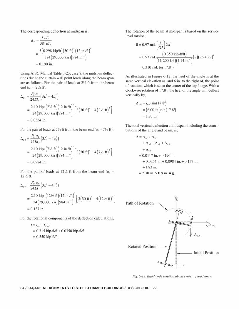
84 / FAÇADE ATTACHMENTS TO STEEL-FRAMED BUILDINGS / DESIGN GUIDE 22
The corresponding defl ection at midspan is,
Δwx
wL
EI=
=( )( )
5
384
5 0 298 30 12
4
4kip/ft ft. in./ft
ksi in.4
( )( )( )
=
3
384 29 000 984
0
,
.1190 in.
Using AISC Manual Table 3-23, case 9, the midspan defl ec-tions due to the curtain wall point loads along the beam span are as follows. For the pair of loads at 22 ft from the beam end (a1 = 22 ft),
Δ pcw
x
P a
EIL a1
1 212
243 4
2 10 2
= −( )
=kips. 2 fft in./ft
ksi in.4
( )( )( )( )
12
24 29 000 9843 3
3
,00 4 2
0 0354
2 2ft ft
in.
( ) − ( )⎡⎣⎢
⎤⎦⎥
=
2
.
For the pair of loads at 72 ft from the beam end (a2 = 72 ft),
Δ pcw
x
P a
EIL a2
2 222
243 4
2 10 7
= −( )
=kips. 2 fft in./ft
ksi in.4
( )( )( )( )
12
24 29 000 9843 3
3
,00 4 7
0 0984
2 2ft ft
in.
( ) − ( )⎡⎣⎢
⎤⎦⎥
=
2
.
For the pair of loads at 122 ft from the beam end (a3 = 122 ft),
Δ pcw
x
P a
EIL a3
3 232
243 4
2 10 12
= −( )
=kips. 2 ft in./ft
ksi in.4
( )( )( )( )
12
24 29 000 9843
3
,330 4 12
0 137
2 2ft ft
in.
( ) − ( )⎡⎣⎢
⎤⎦⎥
=
2
.
For the rotational components of the defl ection calculations,
t t tcw wind= += +kip-ft/ft kip-ft/0 315 0 0350. . fft
kip-ft/ft= 0 350.
The rotation of the beam at midspan is based on the service level torsion,
θ =
=
0 97 2
0 970 350
2.
..
rad.
rad.kip-ft/f
t
GJa
tt
ksi in.in.
4
( )( )( ) ( )( )11 200 1 14
2 76 42
, ..
== °0.310 17.8 )rad. (or
⎛⎝⎜
⎞⎠⎟
As illustrated in Figure 6-12, the heel of the angle is at the same vertical elevation as, and 6 in. to the right of, the point of rotation, which is set at the center of the top fl ange. With a clockwise rotation of 17.8°, the heel of the angle will defl ect vertically by,
Δvrb eodl= °( )= ( )
sin .
. . sin .
17 8
6 00 17 8in °°( )= in.1 83.
The total vertical defl ection at midspan, including the contri-butions of the angle and beam, is,
Δ Δ ΔΔ Δ Δ
Δ
= ++ + +
+=
va w
p p p
vrb
1 2 3
0 0. 1117 0 190
0 0354 0 0984
in. in.
in.
++ +
.
. . iin. in.
in.
in. >
++
=
0 137
1 83
2 30
.
.
. 00.9 in. n.g.
Fig. 6-12. Rigid body rotation about center of top fl ange.
071-114_DG22_Ch06.indd 84 7/17/08 11:44:59 AM

DESIGN GUIDE 22 / FAÇADE ATTACHMENTS TO STEEL-FRAMED BUILDINGS / 85
This total vertical defl ection substantially exceeds the de-fl ection limit, primarily due to the torsional effects. In fact, the torsional effects alone for this beam exceed the stated defl ection limit for the curtain wall system.
The heel of the angle will also defl ect horizontally (inward) by,
Δhrb eod eodl l= − °( )= −
cos .
. . .
17 8
6 00 6 0in 00 17 8
0 287
in
in.
. cos .
.
( ) °( )=
This is an additional out-of-plane movement that must be considered. Note that the horizontal defl ection of the ver-tical leg of the edge angle has been neglected because the fi llet stiffens its vertical leg to the point where the horizontal defl ection will be very small. When the vertical leg is long and the thickness small, the horizontal defl ection may be non-negligible.
Thus, even a spandrel beam as heavy as a W21×50 has sub-stantial torsional rotations. In the following examples, a sys-tem that uses roll beams to reduce the torsion on the spandrel beam will be designed.
Comments:This example shows that an eccentric cladding load will cause signifi cant twist in a spandrel beam that does not have adequate strength or restraint to prevent the twist. Even when eccentricities appear small it may be important to include the effects of torsion on wide-fl ange spandrel beams.
For simplicity, this example does not account for the increase in strong-axis moment of inertia due to the addition of the edge angle. This additional amount can be considered, when desired.
The edge angle size was given as adequate for the purposes of this problem. A complete design of this system would in-clude evaluation of the fl exural strength of the angle section to resist the curtain wall and wind loads.
As an alternative approach, the torsional effects and rotation of the beam can be calculated using a “fl exural analogy.” This method converts the applied torsion into a force couple acting at the top and bottom fl anges of the beam. The force at the top fl ange is resisted by the deck. The force at the bot-tom fl ange is resisted by weak-axis bending of the bottom half of the spandrel beam. The calculated defl ection is then converted into an equivalent rotation about the top fl ange.
The weak-axis moment of inertia of the bottom half of the W21×50 beam is,
II
y FA
y
4in.
in.
=
=
=
224 9
212 5
.
. 44
The equivalent uniform load applied laterally to the bottom fl ange to generate the torsional moment is,
wt
dFA =
= 0.350 kip-ft/ft (12 in./ft)
20.88 in.kip/ft= 0 202.
The corresponding defl ection of the bottom fl ange is,
Δbf FAFA
y FA
w L
EI=
=
5
384
5 0 202
4
kip/ft. ft in./ft
ksi
( ) ( ) ( )( )
30 12
384 29 000 12
4 3
, ..
.
5
10 2
in.
in.
4( )=
Because the beam is forced to rotate about its top fl ange, the full beam depth can be used when calculating the angle of rotation, which is,
θFA
bf FA
d=
⎛
⎝⎜
⎞
⎠⎟
=
−
−
sin
sin. .
1
1 10 2
2
Δ
in
00 8
29 4
.
.
in.
⎛⎝⎜
⎞⎠⎟
= °
In this case, the rotation predicted by the fl exural analogy is approximately 1.7 times that predicted previously using the method in AISC Design Guide No. 9. This illustrates that, while the fl exural analogy requires less computational effort, it can be unrealistically conservative on long spans like this one. The following examples examine this further for shorter spans where the fl exural analogy becomes more appropriate and the savings in computational effort is justifi ed.
As another common and useful simplifi cation for multiple point loads uniformly spaced along the length of a spandrel
071-114_DG22_Ch06.indd 85 7/16/08 4:45:59 PM
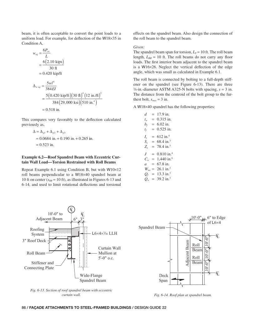
86 / FAÇADE ATTACHMENTS TO STEEL-FRAMED BUILDINGS / DESIGN GUIDE 22
beam, it is often acceptable to convert the point loads to a uniform load. For example, for defl ection of the W18×35 in Condition A,
wP
Leq
cw=
=( )
=
6
6 2 10
300 420
kips
ft
.
. kip/ft
Δw eq
wl
EI
kip/ft
=
=( )
5
384
5 0 420 30
4
. fft in./ft
ksi in.4
( ) ( )( )( )
4 312
384 29 000 510,
8 in= 0 51. .
This compares very favorably to the defl ection calculated previously as,
Δ Δ Δ Δ= + +
= + +p p p1 2 3
0 0684 0 190 0 265in. in.. . . iin.
in.= 0 523.
Example 6.2—Roof Spandrel Beam with Eccentric Cur-tain Wall Load—Torsion Restrained with Roll Beams
Repeat Example 6.1 using Condition B, but with W10×12 roll beams perpendicular to a W18×40 spandrel beam at 10 ft on center (sRB = 10 ft), as illustrated in Figures 6-13 and 6-14, and used to limit rotational defl ections and torsional
effects on the spandrel beam. Also design the connection of the roll beam to the spandrel beam.
Given:The spandrel beam span for torsion, LT = 10 ft. The roll beam length, LRB = 10 ft. The roll beams do not carry any fl oor loads. The fi rst interior beam adjacent to the spandrel beam is a W16×26. Neglect the vertical defl ection of the edge angle, which was small as calculated in Example 6.1.
The roll beam is connected by bolting to a full-depth stiff-ener on the spandrel (see Figure 6-13). There are three w-in.-diameter ASTM A325-N bolts with spacing, s = 3 in. The distance from the centroid of the bolt group to the fur-thest bolt, smax = 3 in.
A W18×40 spandrel has the following properties:
d = 17.9 in. tw = 0.315 in. bf = 6.02 in. tf = 0.525 in.
Ix = 612 in.4
Sx = 68.4 in.3
Zx = 78.4 in.3
J = 0.810 in.4
Cw = 1,440 in.6
a = 67.8 in. Wno = 26.1 in.2
Qf = 13.3 in.3
Qw = 39.2 in.3
Fig. 6-13. Section of roof spandrel beam with eccentric curtain wall. Fig. 6-14. Roof plan at spandrel beam.
071-114_DG22_Ch06.indd 86 7/16/08 4:46:00 PM

DESIGN GUIDE 22 / FAÇADE ATTACHMENTS TO STEEL-FRAMED BUILDINGS / 87
The W10×12 roll beams have the following property:
Ix RB = 53.8 in.4
The W16×26 adjacent interior beam has the following property:
Ixa = 301 in.4
Solution:
The loading is as illustrated in Figure 6-15. For simplicity, the wind and curtain wall loads (see Figure 6-16) will be converted into equivalent uniformly distributed torsional moments on the spandrel beam. The equivalent uniformly distributed torsional moment due to the curtain wall loads on the spandrel beam is,
t w h ecw curt c cw=
= kip/ft ft20 015 28. ( ) 99 in.
12 in./ft
= 0.315 kip-ft/ft
⎛⎝⎜
⎞⎠⎟
The equivalent uniformly distributed torsional moment due to wind on the spandrel beam is,
t ph
ewind w v=⎛⎝⎜
⎞⎠⎟
( )
=
2
0 0301
kip/ft2.44
2
0 0
ft 2 in.
12 in./ft
⎛⎝⎜
⎞⎠⎟
⎛⎝⎜
⎞⎠⎟
= . 3350 kip-ft/ft
The required strength for torsional effects is,
t t tu cw wind
= 1.2 + 0.8
= 1.2 kip-ft/ft0 315.(( ) ( )+ 0.8 kip-ft/ft
= kip-ft/
0 0350
0 406
.
. fft
Because the roll beams restrain the torsion on the spandrel beam, they impose vertical reactions on the spandrel beam and the adjacent interior beam (see Figure 6-17). Thus, to calculate the required fl exural strength of the spandrel beam, the moments in the roll beams must fi rst be determined. Also for simplicity, the torsional continuity in the spandrel beam at the roll beams will be ignored, and conservatively it will be assumed that the spandrel beam is torsionally pinned at each roll beam. Alternatively, it is permissible to consider the benefi cial effects of the continuity.
Fig. 6-15. Loads on roof spandrel beam.
Fig. 6-16. Torsional loads on spandrel beam.
Fig. 6-17. Loads on and reactions due to roll beam.
071-114_DG22_Ch06.indd 87 7/16/08 4:46:00 PM

88 / FAÇADE ATTACHMENTS TO STEEL-FRAMED BUILDINGS / DESIGN GUIDE 22
The torsional moment in the spandrel on each side of each roll beam is,
T tL
u uT=
⎛⎝⎜
⎞⎠⎟
= ( )⎛⎝
2
0 40610
2kip-ft/ft
ft. ⎜⎜
⎞⎠⎟
= kip-ft2 03.
Each roll beam provides a fl exural moment that resists twice this torsional moment (Tu is present on both sides of each roll beam).
RT
LTu
u
RB
=
=( )
=
2
2 2 03
0 40
kip-ft
10 ft
.
. 66 kip
The additional vertical reaction on the spandrel beam due to the self weight of the roll beam is,
R wL
RBu RBRB=
= ( )
1 22
1 2 0 012
.
. . kip/ft10 ft
2
kip
⎛⎝⎜
⎞⎠⎟
⎛⎝⎜
⎞⎠⎟
= 0 0720.
The total factored point load on the spandrel beam at each roll beam is,
P R RRBu Tu RBu
= += 0.406 kip + 0.0720 kip
0.478 kip=
The uniformly distributed dead load on the spandrel beam is,
w w w tD beam dead r
= +
= +kip/ft kip0 040 0 015. . //ft ft
kip/ft
2 5 50
0 123
.
.
( )=
and the uniformly distributed snow load on the spandrel beam, ws = 0.165 kip/ft, as calculated previously. The fac-tored load is,
w w wu D s= +
= ( ) +
1 2 1 6
1 2 0 123 1 6 0 1
. .
. . . .kip/ft 665
0 412
kip/ft
kip/ft
( )= .
As calculated previously, Pu = 2.52 kips. From AISC Design Guide No. 9 Appendix B, case 4 with,
L
aT =
( )
=
10
1 77
ft 12 in./ft
67.8 in..
The torsional functions at the middle of the torsional spans (span between roll beams) are,
θu
u
GJ
t a
1
20 037
2= . rad.
⎛⎝⎜
⎛⎝⎜
⎞⎠⎟
⎞⎠⎟
rad.θu
u
GJ
t″ .= 0 24
⎛⎝⎜
⎞⎠⎟
The torsional function at the ends of the torsional spans (at the roll beams) is,
θu
u
GJ
t
L
a.
100 04
2≈ rad.′
⎛⎝⎜
⎞⎠⎟
⎛⎝⎜
⎞⎠⎟
θ″′ is not applicable because warping does not affect the shear stresses in the web.
For the interaction of fl exure and torsion at midspan,
rad.
rad.
″ =
=
θuut
GJ0 24
0 240 406
.
.. kip-ft/ft
ksi in.4
( )( )( )11 200 0 810, .
rad./in.2= × −1 07 10 5.
⎛⎝⎜
⎞⎠⎟
σ θwsu no uEW= ″
= ( )(29,000 ksi 26.1 in.2 )) ×( )=
1.07 10 rad./in.
ksi
−5 2
8 10.
Mw L
Ps s s
P suu
uc c c
RBu RB= + + +⎛⎝⎜
⎞⎠⎟
+2
8 2
3
2
5
2
==( )
+
0 412 30
8
2 52
2.
.
kip/ft ft
kips55
2
3 5
2
5 5
2
0
ft ft ft+
( )+
( )⎛
⎝⎜
⎞
⎠⎟
+ .4478 10
109
kip ft
kip-ft
( )=
φb y xF S =0.90 ksi in.
in./ft
350 68 4
12
( )( ).
= 257 kip-ft
071-114_DG22_Ch06.indd 88 7/17/08 11:45:50 AM

DESIGN GUIDE 22 / FAÇADE ATTACHMENTS TO STEEL-FRAMED BUILDINGS / 89
Using AISC Design Guide No. 9 Equation 4-16a, the interac-tion of combined normal stresses assuming the predominant limit state is yielding is,
M
M Fu
b n
wsu
yφσ
+0 9
109
257.
kip-ft
kip-ft
8.10 kksi
0.9(50 ksi)
= 0 604. ≤≤ 1.0 o.k.
For the interaction of shear and torsion at the support,
θ ′ .
..
=
=
0 0410
0 040 406
2
rad.
rad.kip
t
GJ
a
Lu
--ft/ft
ksi in.
in.4
( )( )( )11 200 0 810
10 67 8
, .
.(( )( )
=
2
30 12
0 000229
ft in./ft
rad./in..
⎛⎝⎜
⎛⎝⎜
⎞⎠⎟
⎞⎠⎟
τ θt wGt=
= ( )′
, . . .ksi in r11 200 0 380 0 000229 aad./in
ksi
.
.
( )= 0 975
θ″′ is not applicable because warping does not affect the shear stresses in the web.
Vw L
P Puu
u RBu= + +
= +
23
0 412
23
kip/ft(30 ft).22 52 0 478
14 2
. .
.
kips kip
kips
( ) +
=
From AISC Specifi cation Sections G1 and G2.1 (and using φv = 1.0 and Cv = 1.0 because this W-shape has h/tw ≤ 2.24 E /Fy), the available shear strength is,
φ φv n v y w vV F dt C=
= ( )( )0 6
1 00 0 6 50 2
.
. . ksi 00 8 0 380 1 0
237
. . . .in. in
kips
( )( )( )=
The interaction of pure torsion shear stress and direct shear is,
V
V F
u
v n
t
yφ
τ+ ( ) = +
0 9 0 6
14 2
. .
. kips
237 kips
0.975 ksi
0.9 0.6 50 ksi( )( )1.0= ≤0 0960. o.k.
As calculated previously, wD = 0.123 kip/ft, wS = 0.165 kip/ft, and Pcw = 2.10 kips.
The service torsion on the spandrel beam is,
t = tcw + twind
= 0.315 kip-ft/ft + 0.0350 kip-ft/ft
= 0.350 kip-ft/ft
The service torsional moment on each roll beam is,
T tLT=
⎛⎝⎜
⎞⎠⎟
=⎛⎝⎜
⎞⎠⎟
2
0 35010
2kip-ft/ft
ft.
kip-ft= 1 75.
The service vertical reaction on the spandrel due to the end moment on the roll beam is,
RT
LT
RB
=
=( )
=
2
2 1 75
0 350
kip-ft
10 ft
k
.
. iip
The service vertical reaction on the spandrel due to the self weight of the roll beam is,
R wL
RB RBRB=
=⎛⎝⎜
⎞⎠⎟
2
0 012 kip/ft10 ft
2.
kip= 0 0600.
The service point load on the spandrel at each roll beam is,
P R RRB T RB= += 0.350 kip + 0.0600 kip
0.410 kip=
The uniform service load is,
w w wD S= +==
lb/ft + 0. lb/ft0 123 165
0
.
..288 kip/ft
The corresponding defl ection at midspan is,
Δw
x
wl
EI=
=( )( )
5
384
5 0 288 30 12
4
4kip/ft ft. iin./ft
ksi in.4
( )( )( )
=
3
384 29 000 612
0 2
,
. 996 in.
071-114_DG22_Ch06.indd 89 7/16/08 4:46:01 PM

90 / FAÇADE ATTACHMENTS TO STEEL-FRAMED BUILDINGS / DESIGN GUIDE 22
Using AISC Manual Table 3-23, case 9, the midspan defl ec-tions due to the curtain wall point loads along the beam span are as follows. For the pair of loads at 22 ft from the beam end (a1 = 22 ft),
Δp
cwP a
EIL a1
1 212
12
3
4
2 10 2
= −⎛⎝⎜
⎞⎠⎟
=kips. 22 ft in./ft
ksi in.4
( )( )( )( )
12
12 29 000 612
3
43
3
,00 2
0 0285
2 2ft ft
in.
( ) − ( )⎡
⎣⎢
⎤
⎦⎥
=
2
.
For the pair of loads at 72 ft from the beam end (a2 = 72 ft),
Δp
cwP a
EIL a2
2 222
12
3
4
2 10 7
= −⎛⎝⎜
⎞⎠⎟
=kips. 22 ft in./ft
ksi in.4
( )( )( )( )
12
12 29 000 612
3
430
3
,fft ft
in.
( ) − ( )⎡
⎣⎢
⎤
⎦⎥
=
2 27
0 0791
2
.
For the pair of loads at 122 ft from the beam end (a3 = 122 ft),
Δp
cwP a
EIL a3
3 232
12
3
4
2 10 1
= −⎛⎝⎜
⎞⎠⎟
=kips. 22 12
12 29 000 612
3
43
32 ft in./ft
ksi in.4
( )( )( )( ),
00 12
0 111
2 2ft ft
in.
( ) − ( )⎡
⎣⎢
⎤
⎦⎥
=
2
.
For both roll-bracing beams 10 ft from the beam end (aRB = 10 ft),
ΔpRB
RB RBRB
P a
EIL a= −
⎛⎝⎜
⎞⎠⎟
=
12
3
4
0 410
2 2
k. iip ft in./ft
ksi in.4
10 12
12 29 000 612
33( )( )
( )( ), 4430 10
0 0191
2 2ft ft
in.
( ) − ( )⎡
⎣⎢
⎤
⎦⎥
= .
The total fl exural deformation of spandrel beam is,
Δ Δ Δ Δ Δ Δf w p p p RB
= + + + +( )= +
2
0 296 2 0 02
1 2 3
in.. . 885 0 0791 0 111 0 0191
0
in. in. in. in.+ + +( )=
. . .
..770 in.
The rotation of the spandrel beam at midspan (between roll beams) is,
θ θ= =( )( )2 2 0 037 0 350 67 82F ta
GJ
. . .rad. kip-ft/ft iin.
ksi in.
rad.
4
( )( )( )
=
2
11 200 0 810
0 0131
, .
. (( . )or 0 751°
The rotation of the roll beam (see Figure 6-18) is,
θRB
RB
xRB
TL
EI= =
( )( )2
3
2 1 75 10 12. kip-ft ft in./ft(( )( )( )
=
2
3 29 000 53 8
0 00108
, .
.
ksi in.
rad
4
.. (o )r 0 617. °
The rotation of spandrel beam at midspan including the rota-tion contribution from the end of the roll beams is,
θ θ θtotal RB
= += +=
0 751° 0.0617°0
.
..813°
Assuming no load sharing between the spandrel and the ad-jacent beam, the total vertical defl ection of the adjacent roof beam at the roll beam location due to the roll beam reaction is,
Δadj
RB RB
xaRB
P s
EIL s= −( )
=
243 4
0 410
2 2
kip. 110 12
24 29 000 3013 30
3ft in./ft
ksi in.4
( )( )( )( ),
fft ft
in.
( ) − ( )⎡⎣⎢
⎤⎦⎥
=
2 24 10
0 0778.
The rotational deformation of the spandrel is calculated, as illustrated in Figure 6-19. The initial horizontal and vertical distances between the centroid of the W18×40 and the bot-tom of the curtain wall support angle are,
xi = 6 in. yi = 0 in.
The distance between the beam centroid and the curtain wall attachment point is,
r x yi i
= +
= ( ) + ( )=
2 2
2 26 0
6 00
in. in.
in..
Fig. 6-18. Rotation of roll beam.
MRB = 2 × T
θRB
θRB = MRBLRB
3EIxRB
071-114_DG22_Ch06.indd 90 7/16/08 4:46:01 PM

DESIGN GUIDE 22 / FAÇADE ATTACHMENTS TO STEEL-FRAMED BUILDINGS / 91
The initial angle of the curtain wall centroid with respect to the horizontal is,
α =⎛
⎝⎜⎞
⎠⎟
=⎛⎝⎜
⎞⎠⎟
−
−
tan
tan.
1
1 0
6
y
xi
i
in
in.
0= °
The fi nal angle of the curtain wall attachment after rotation is,
β α θ= −== − °
total
0° − 0.813°0 813.
The fi nal horizontal and vertical curtain wall position with respect to the beam centroid is,
x rf = ( )= ( ) − °( )=
cos
. . cos .
.
β
in6 00 0 813
6 000 in.
y rf = ( )= ( ) − °( )= −
sin
. . sin .
.
β
in6 00 0 813
0 00851 in.
The out-of-plane movement of the angle due to beam rota-tion is,
Δhrb ifx x= −
=
=
6.00 in. − 6.00 in.
00 in. (small enough that it is negligible)
The rigid-body translation at the centerline of the curtain wall due to rotation of the spandrel is,
Δvrb i fy y= −
= − −( )=
in. 0.0851 in.0
00.0851 in.
The total vertical movement at the curtain wall attachment point (the sum of the fl exural and rotational defl ections) is,
Δ Δ Δv f vrb= +
= += ≤in. 0
0 770 0 0851
0 855
. .
. ..90 in. o.k.
For the design of the roll beam connection to the spandrel, the vertical shear force on the bolt group is equal to the reac-tion at the end of the roll beam,
V RuRB Tu= = 0 406. kip
The required fl exural strength of the bolt group is,
M TuRB u2
kip-ft
=
= ( )2 2 03.
== kip-ft4 06.
The eccentricity on the bolt group is,
eM
Vbolt
uRB
u RB
=
=( )kip-ft 12 in./ft4 06.
00 406
120
. kips
in.=
The eccentricity on the bolts is larger than the data tabulated in AISC Manual Table 7-7. In this case, the elastic method can be used as illustrated in Figure 6-20. Alternatively, the instantaneous center method and an iterative calculation similar to that used to determine the values in AISC Manual Table 7-7 can be used. The polar moment of inertia of the bolt group is,
J sbolt max=
= ( )=
2
2 3
18 0
2
2
in.
in.. 22
Fig. 6-19. Rigid body rotation about center of top fl ange.
071-114_DG22_Ch06.indd 91 7/16/08 4:46:02 PM

92 / FAÇADE ATTACHMENTS TO STEEL-FRAMED BUILDINGS / DESIGN GUIDE 22
The maximum horizontal shear force due to torsion on a single bolt is,
rM s
Jut
uRB max
bolt
=
=( )kip-ft 3 in. i4 06 12. nn./ft
18.0 in.kips
2
( )
= 8 12.
The maximum vertical shear force on a single bolt is,
rV
nut
uRB=
=
=
kip
3kip
0 406
0 135
.
.
The resultant maximum shear force for a single bolt is,
( )( )r r
8.12 kips
8.12 kips
0.135 kips
ru ut uv
= +
=
=
+
2
2 2
From AISC Manual Table 7-1, the available strength of a w-in.-diameter ASTM A325-N bolt in single shear is,
φvrn = 15.9 kips > ru o.k.
Other checks for this connection, including the strength of the plate for bolt bearing and the strength of the weld to the beam, are required, but left as an exercise for the reader.
Comments:The use of roll beams substantially reduces the torsional ro-tation of the spandrel beam, which allows the use of lighter, shallower spandrels, particularly for spandrels with longer spans.
The effects of torsional continuity in the spandrel beam at the roll beams are ignored in this example. When desired, these effects can be considered, and may reduce the torsional rotations of the spandrel beam further.
If the top fl ange of the W10×12 roll beam is fl ush with the top of the spandrel beam and its web is coped to facilitate the connection to the spandrel beam, it may be diffi cult to install three bolts in the full-depth stiffener. The designer could consider dropping the top fl ange of the roll beam or using a deeper section (such as a W12).
Example 6.3—Roof Spandrel Beam with Eccentric Curtain Wall Load—Torsion Avoided with HSS and Roll Beams
Repeat Example 6.2, but with an HSS5×3×4 spanning as shown in Figures 6-21 and 6-22 between W12×16 roll beams.
Given:An ASTM A500 Grade B HSS5×3×4 resists all torsion associated with the curtain wall support, and its span for torsion, LT = 10 ft. The architect has set the edge angle face at 1 ft 3 in. from the centerline of the spandrel beam; thus, leod = 15 in.
Fig. 6-21. Section of roof spandrel beam with edge HSS and roll beams.
Fig. 6-20. Forces on bolts at roll beam to spandrel beam connection.
071-114_DG22_Ch06.indd 92 7/16/08 4:46:02 PM
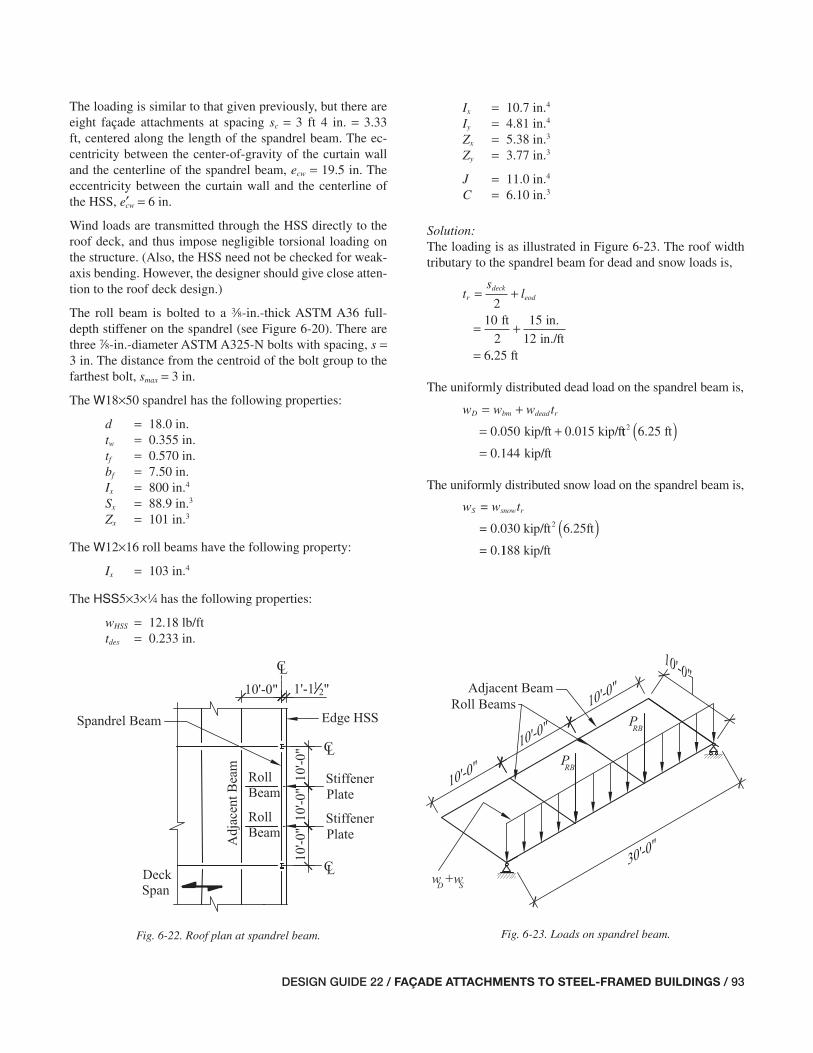
DESIGN GUIDE 22 / FAÇADE ATTACHMENTS TO STEEL-FRAMED BUILDINGS / 93
The loading is similar to that given previously, but there are eight façade attachments at spacing sc = 3 ft 4 in. = 3.33 ft, centered along the length of the spandrel beam. The ec-centricity between the center-of-gravity of the curtain wall and the centerline of the spandrel beam, ecw = 19.5 in. The eccentricity between the curtain wall and the centerline of the HSS, e′cw = 6 in.
Wind loads are transmitted through the HSS directly to the roof deck, and thus impose negligible torsional loading on the structure. (Also, the HSS need not be checked for weak-axis bending. However, the designer should give close atten-tion to the roof deck design.)
The roll beam is bolted to a a-in.-thick ASTM A36 full-depth stiffener on the spandrel (see Figure 6-20). There are three d-in.-diameter ASTM A325-N bolts with spacing, s = 3 in. The distance from the centroid of the bolt group to the farthest bolt, smax = 3 in.
The W18×50 spandrel has the following properties:
d = 18.0 in. tw = 0.355 in. tf = 0.570 in. bf = 7.50 in. Ix = 800 in.4
Sx = 88.9 in.3
Zx = 101 in.3
The W12×16 roll beams have the following property:
Ix = 103 in.4
The HSS5×3×4 has the following properties:
wHSS = 12.18 lb/ft tdes = 0.233 in.
Ix = 10.7 in.4
Iy = 4.81 in.4
Zx = 5.38 in.3
Zy = 3.77 in.3
J = 11.0 in.4
C = 6.10 in.3
Solution:The loading is as illustrated in Figure 6-23. The roof width tributary to the spandrel beam for dead and snow loads is,
ts
lrdeck
eod= +
= +
=
210
2
15
126
ft in.
in./ft..25 ft
The uniformly distributed dead load on the spandrel beam is,
w w w tD bm dead r= +
= +kip/ft kip/f0 050 0 015. . tt ft
kip/ft
2 6 25
0 144
.
.
( )=
The uniformly distributed snow load on the spandrel beam is,
w = w t
=
=
S snow r
30 kip/ft 6.25ft20 0
0
.
.
( )1188 kip/ft
Fig. 6-22. Roof plan at spandrel beam. Fig. 6-23. Loads on spandrel beam.
071-114_DG22_Ch06.indd 93 7/16/08 4:46:03 PM

94 / FAÇADE ATTACHMENTS TO STEEL-FRAMED BUILDINGS / DESIGN GUIDE 22
The factored uniform load is,
w w wu D S= +
= . + .
1.2 1.6
1.2 kip/ft 1.60 144 0 1( ) 888 kip/ft
= 0.474 kip/ft
( )
The half-depth plate between the spandrel and the HSS has the following depth,
dd
tpl f= −
= −
=
2in.
in.18 0
20 570
8
..
.443 in.
An 8½-in. plate depth will be used.
The HSS is supported at each column and each roll beam, and must resist the vertical load and torsion associated with the curtain wall attachment loads, as shown in Figure 6-24. For simplicity of calculation, it will be assumed that the HSS is torsionally restrained at each roll beam.
Each wind point load on the HSS is,
P ph
swind w c=
= .
2
kip/ftf2
⎛⎝⎜
⎞⎠⎟
0 03014 tt
2ft
= 0.700 kip
⎛⎝⎜
⎞⎠⎟
( )3 33.
Each curtain wall gravity point load on the HSS is,
P w h scw curt c c
.
=
= ( )kip/ft 28 ft20 015 33 33
1 40
.
.
ft
kips
( )=
The torsional moment at each curtain wall point load is,
T P ecw cw= ′
=⎛⎝⎜
⎞⎠⎟
kips6 in.
12 in./ft1 40.
== 0 70. 0 kip-ft
The factored loads and moment are,
P Pu w wind
kip
=
= ( )=
0 8
0 8 0 700
0 56
.
. .
. 00 kip
P Pu cw cw= 1.2
= 1.2(1.40 kips)
= 1.68 kips
T Tu =
= ( )=
1 2
1 2 0 700
.
. . kip-ft
0.840 kip-fft
The uniformly distributed load on the HSS due to self weight is,
w wu HSS HSS
0.01218 kip/ft
=
= ( )1 2
1 2
.
.
0.0 kip/ft= 146
Using AISC Manual Table 3-22c to calculate the moment at the interior support of a continuous beam with three equal spans, the strong-axis required fl exural strength is,
M P L w Lux u cw T u HSS T= +
=
0 267 0 10
0 267
2. .
. 11 68 10
0 10 0 0146 10
.
. .
kips ft
kip/ft f
( )( )+ ( ) tt
kip-ft
( )=
2
4 63.
The required shear strength for the HSS is,
V P w Lux u cw u HSS T= +
=
1 27 0 6
1 27 1 68
. .
. . kipps kip/ft ft( ) + ( )( )=
0 6 0 0146 10
2 22
. .
. kkipsFig. 6-24. Loads on edge HSS between roll beams.
071-114_DG22_Ch06.indd 94 7/16/08 4:46:03 PM

DESIGN GUIDE 22 / FAÇADE ATTACHMENTS TO STEEL-FRAMED BUILDINGS / 95
From AISC Manual Table 1-11, the HSS wall slenderness ratio h/tw = 18.5. Because this is less than 2.45 E /Fy , per AISC Specifi cation Section H3.1, the torsional design strength is,
φ φT n T crT F C=
=( )( )( )0 90 0 6 46
12
. . ksi 6.10 in.
in
3
../ft
12.6 kip-ft=
The shear area for strong-axis shear is,
( )( )A ht
d t t
wx des
des des
=
= −
=
2
2 3
2 5 iin. in. in.− ( )⎡⎣ ⎤⎦( )=
3 0 233 0 233
2 00
. .
. in.2
For unstiffened webs with h/t kw v< =260, 5
.1 10 kkE
Fv
y
=⎛⎝⎜
⎛⎝⎜
⎞⎠⎟
⎞⎠⎟
=
1 10 529 000
46
61 8
.,
.
ksi
ksi
Because h/tw < 61.8, Cv = 1.0. From AISC Specifi cation Sec-tion G2.1(b) the strong-axis design shear strength is,
k
φ φv nx v y wx vV F A C=
= ( )0 6
1 00 0 6 46
.
. . ssi in.
kips
2( )( )( )=
2 00 1 0
55 2
. .
.
Flange local buckling and web local buckling do not control the fl exural strength of the HSS used. Therefore, the design fl exural strength of the HSS is based on the limit state of yielding,
φ φb nx b y xM F Z=
=( )( )0 90 4
12
. 6 ksi 5.38 in.
in./f
3
tt
18.5 kip-ft=
The ratio of required torsional strength to design torsional strength per the AISC Specifi cation Section H3.2 is,
T
Tu
T nφ=
=
0 84
12 6
0 0667
.
.
.
0 kip-ft
kip-ft
Because this ratio is less than 20%, torsional effects can be neglected and the available fl exural strength is,
φbMnx = 18.5 kip-ft > Mux o.k.
The available shear strength is,
φvVnx = 5.22 kips > Vux o.k.
As with the previous example, the roll beams resist the twist of the cladding system and, in doing so, impose downward vertical loads on the spandrel beam. The loads on the span-drel beam from the HSS can be obtained using the coef-fi cients from the continuous beam tables presented in AISC Manual Table 3-22c. The point loads on the spandrel at the one-third points (at the roll beams) are calculated as illus-trated in Figure 6-25. The service vertical reaction on the spandrel beam due to the self-weight of the HSS is,
( )R w LHSS HSS T=
=
11
1011
100 01218 kip/ft.(( )( )
=
10
0 134
ft
kip.
The service vertical reaction on the spandrel beam due to the curtain wall is,
R P Pcw cw cw= +
= ( ) +
2 27
2 27 1 40 1 40
.
. . .kips kkips
4.58 kips=
Note, with two intermediate curtain wall point loads and one more at each roll beam, the torsional moment resisted by each roll beam is 3T.
Fig. 6-25. Loads on and reactions due to roll beam.
071-114_DG22_Ch06.indd 95 7/16/08 4:46:04 PM

96 / FAÇADE ATTACHMENTS TO STEEL-FRAMED BUILDINGS / DESIGN GUIDE 22
The service moment on each roll beam is,
( )M R R lB
TRB HSS cw eod= + −⎛⎝⎜
⎞⎠⎟
+
=
23
0 13. 44 4 58 153
2
12
kip kips in.in.
in./
+( ) −⎛⎝⎜
⎞⎠⎟
.
fft
kip-ft
kip-ft
+ ( )=
3 0 700
7 40
.
.
The service vertical reaction on the spandrel beam due to the end moment on the roll beam is,
RM
LT
RB
RB
=
=
=
kip-ft
ft0 ki
7 40
100 74
.
. pp
The service vertical reaction on the spandrel beam due to the self-weight of the roll beam is,
R wL
RB RBRB=
=⎛⎝⎜
⎞⎠⎟
2
0 016 kip/ft10 ft
2.
== 0 0800. kip
The service point load on the spandrel beam at each roll beam is,
P R R R RRB HSS cw T RB= + + += +kip kip0 134 4 58. . ss 0.740 kip + 0.0800 kip
kips
+= 5 53.
The factored point load on the spandrel beam at each roll beam is,
P PRBu RB=
= ( )=
1 2.
1.2 5.53 kips
6.664 kips
The required shear strength of the spandrel beam at each end is,
= +Vw L
Puu
RBu
=( )
+
20 474 30
26 64
kip/ft ftk
.. iips
kips= 13 7.
The required fl exural strength of the spandrel beam at mid-span is,
= +Mw L
P Luu
RBu T
=( )
+
2
2
8
0 474 30
86
kip/ft ft..664 10
120
kips ft
kip-ft
( )( )=
The available fl exural strength is,
φ φb n b y xM F Z=
=( )( )ksi 101 in.30 90 50
1
.
22379
in./ftkip-ft >= Mu o.k.
From AISC Specifi cation Sections G1 and G2.1 (and using φv = 1.0 and Cv = 1.0 because this W-shape has h/tw ≤ 2.24 E /Fy), the available shear strength is,
φ φv n v y w vV F dt C=
= ( )( )0 6
1 00 0 6 50
.
. . ksi 18.0 iin. in.
kips
( )( )( )= >
0 355 1 0
192
. .
Vu o.k..
The defl ection of the HSS and spandrel beam is as shown in Figure 6-26. The vertical defl ection at the midspan of the HSS is calculated assuming that it is simply supported at each roll beam. This assumption is conservative, and could be improved upon with more refi ned analysis. Defl ection at the HSS midspan with point loads at the one-third points of the span (using AISC Manual Table 3-23, cases 9 and 1) is,
= +ΔHSScw T
x
HSS T
x
P L
EI
w L
EI
=
3 4
28
5
384
1 40. kips ft in./ft
ksi
( )( ) ( )( )
10 12
28 29 000 10
3 3
, ..
.
7
5 0 01218 10 124
in.
kip/ft ft in./f
4( )
+( )( ) tt
ksi in.4
( )( )( )
=
384 29 000 10 7
0 28
3
, .
. 77 in.
The torsional rotation of the HSS at midspan is,
θHSS
TTL
GJ=
⎛⎝⎜
⎞⎠⎟
=
⎛
3
0 70010
3kip-ft
ft.
⎝⎝⎜⎞⎠⎟
( )( )
12 in./ft
ksi in.
2
411 200 11 0, .
rad. or 0.156= ( )0 00273. o
071-114_DG22_Ch06.indd 96 7/17/08 11:46:35 AM

DESIGN GUIDE 22 / FAÇADE ATTACHMENTS TO STEEL-FRAMED BUILDINGS / 97
The vertical displacement of the HSS due to rotation of the HSS between roll beams at midspan is,
ΔHSS HSS
Bθ θ=
=⎛⎝⎜
⎞2
0 00273 rad.3 in.
2.
⎠⎠⎟
⎛⎝⎜
⎞⎠⎠⎟
= in.0 00409.
This deformation is small because the HSS is a closed shape and is stiff in torsion. Thus, this defl ection is neglected in the rest of this example. The vertical defl ection of the spandrel beam at the roll beam (reduced from AISC Manual Table 3-23, cases 9 and 1) is,
( )D S= +ΔsRB
x x
P L
EI
w w L
EI
+
=
= 0.570 in.
5
162
22
1 944
5 5
3
34
4
4
,
.553 30 12
162 29 000
3 3kips ft in./ft
ksi
( )( ) ( )( , ))( )
++
800 in.
kip/ft ki
4
22 0 144 0 188. . pp/ft 30 ft 12 in./ft
1,944(29,000 ksi) (800 in. )( ( () ) )
The rotation of the roll beam due to the eccentricity of the edge HSS (see Figure 6-27) is,
θRBRB RB
xRB
M L
EI=
=( )
3
7.40 kip-ft 10 ft 12 in../ft
3 29,000 ksi 103 in.
0.001
4
( )( )( )
=
2
119 rad. or 0.0681( )°
The rigid body translation of the corner of the HSS due to rotation of the roll beam assuming a small angle of rotation (where θ = sin θ) is,
ΔRB RB eodl=
= ( )θ
rad. 15 in.0 00119.
in.= 0 0179.
This deformation is typically small. It has been neglected in the rest of this example. The total vertical displacement of the HSS at center of the span is limited to 0.90 in. in Example 6.1,
Δ Δ Δtotal HSS s= += +in. in.0 287 0 570. .
in. 0.90= ≤0 857. o.k.
The design of the roll beam connection to the spandrel beam (see Figure 6-28) begins with the calculation of the factored moment on each roll beam,
M MuRB RB= 1.2
kip-ft= ( )1 2 7 40. .
kip-ft= 8 88.
The factored vertical shear on the bolt group is,
V RuRB T=
= ( )=
1 2
1 2 0 740
0 8
.
. .
.
kip
888 kip
Fig. 6-27. Rotation of roll beam.Fig. 6-26. Rotation of spandrel at roll beam.
071-114_DG22_Ch06.indd 97 7/16/08 4:46:04 PM

98 / FAÇADE ATTACHMENTS TO STEEL-FRAMED BUILDINGS / DESIGN GUIDE 22
Fig. 6-28. Forces on bolts at roll beam to spandrel beam connection.
The eccentricity on the bolt group is,
eM
Vbolt
uRB
u RB
=
=( )kip-ft 12 in./ft8 88.
00 888
120
. kip
in.=
The eccentricity on the bolts is suffi ciently large that it exceeds the parameters that are tabulated in AISC Manual Table 7-7 for eccentrically loaded bolt groups. In this case, the elastic method is applied. Alternatively, the instanta-neous center method and an iterative calculation similar to that used to determine the values in AISC Manual Table 7-7 can be used.
The polar moment of inertia of the bolt group is,
J sbolt =
= ( )=
2
2 3
18 0
2
2
max
.
in.
in.2
The maximum horizontal shear force due to torsion on a single bolt is,
rM s
Jut
uRB
bolt
=
=( )
max
. kip-ft 3 in. i8 88 12 nn./ft
18.0 in.kips
2
( )
= 17 8.
The maximum vertical shear on a single bolt is,
rV
nuv
uRB=
=
=
kip
3kip
0 888
0 296
.
.
The resultant required shear strength on a single bolt is,
( )r r
17.8 kips 0.296 kip
ru ut uv= +
=
17.8 kips=
+ ( )
2 2
2 2
The strength of one d-in.-diameter A325-N bolt in single shear (AISC Manual, Table 7-1) is,
φvrn = 21.6 kips > ru o.k.
For the design of the stiffener plate, the unbraced length for bending is,
L l BbPL eod= −= −=
in. in.
12 i
15 3
nn.
The slenderness of the plate for yielding and lateral-torsional buckling limit states per AISC Specifi cation Section F11 is,
t
bPL PL
PL (a in. 22
( ))
82 in.12 in.L d2
= = 725
The limiting plate slenderness for yielding is,
0 08 0 08 29 000
3664 4
. . ,.
E
Fy
=( )
=ksi
ksi
The limiting plate slenderness for lateral-torsional buckling is,
1 9 1 9 29 000
361,530
. . ,E
Fy
=( )
=ksi
ksi
The values of My and Mp are,
M F S
Ft d
y y x
yPL PL
=
=⎛
⎝⎜⎞
⎠⎟
=
2
6
36 ksiia nn. in. ft
in.
8
6
1
12
22( )⎛
⎝⎜⎜
⎞
⎠⎟⎟
⎛⎝⎜
⎞⎠⎟
kip-ft= 13 6.
071-114_DG22_Ch06.indd 98 7/17/08 11:48:01 AM

DESIGN GUIDE 22 / FAÇADE ATTACHMENTS TO STEEL-FRAMED BUILDINGS / 99
Fig. 6-29. Sections of roof spandrel beam with edge HSS and kickers.
Fig. 6-30. Roof plan at spandrel beam.
M Ft d
p yPL PL=⎛
⎝
⎜⎜⎜⎜⎜
⎞
⎠
⎟⎟⎟⎟⎟⎟
=
2
4
36 ina .. in. ft
in.
8
4
1
12
22( )⎛
⎝
⎜⎜⎜⎜⎜⎜⎜
⎞
⎠
⎟⎟⎟⎟⎟⎟⎟⎟
⎛
⎝⎜⎜⎜⎜⎜
⎞
⎠⎟⎟⎟⎟
= kip-ft20 3.
The plate available fl exural strength (assuming C b = 1.0) is,
φb nbPL PL
PL
yPLML d
t
F
E= −
×
⎛
⎝⎜⎞
⎠⎟⎡
⎣0 90 1 52 0 274
2. . .⎢⎢
⎢
⎤
⎦⎥⎥
≤
= −
M My b pφ
in.0 90 1 52 0 274
12. . .
88 in.
in.
ksi
ksi
2
a
( )( )
⎛
⎝⎜⎜
⎞
⎠⎟⎟
⎛⎝
2
36
29 000,⎜⎜⎞⎠⎟
⎡
⎣
⎢⎢
⎤
⎦
⎥⎥( )13.6 kip-ft
kip-ft
kip-ft
≤=
0 90 20 3
15 6
. ( . )
. ≤≤= >
18 3
15 6
.
.
kip-ft
kip-ft MuRB o..k.
The a-in.-thick plate is adequate for fl exure.
Comments:A similar plate would also be required at the columns at each end of the 30-ft span. In a complete design, the designer would also check other limit states, such as the attachment of this plate to the columns, the shear strength of the plate, the strength of the roll beam, the strength of the adjacent roof beam, the bolt bearing strength of the plate, and sizing the weld between the plate and the beam. The designer should also consider the effects of the unbraced bottom fl ange of the roll beam on its fl exural strength.
Example 6.4—Roof Spandrel Beam with Eccentric Curtain Wall—Torsion on Spandrel Avoided by Kickers
Reconsider the 30-ft-long spandrel beam investigated in Ex-ample 6.3 with the curtain wall supported at sc = 3 ft 4 in. on center. In this case, however, use single-angle diagonal kickers spaced at 10 ft on center along the spandrel to brace the stiffener plates. The curtain wall is supported by an HSS spanning between the stiffener plates as illustrated in Figures 6-29 and 6-30. The same load and defl ection criteria apply as in the previous example. The roof deck is typically welded to the spandrel beam with s-in.-diameter puddle welds at 112 in. on center.
Check the strength of the edge HSS, spandrel beam, and kick-er considering torsional effects. Also, check the defl ection
of the spandrel beam and edge HSS assembly at the beam midspan considering torsional effects. The welds between the roof deck and the spandrel beam and adjacent beam to resist the horizontal component of the load in the kicker and the bending of the stiffener plate must be considered.
Given:For this example assume the controlling load combination for strength is 1.2D + 1.6S + 0.8W (D + S + W for defl ection). The HSS resists all torsion associated with the curtain wall support and its span, LT = 10 ft. The eccentricity between the curtain wall and the centerline of the HSS, e′cw = 6 in.
071-114_DG22_Ch06.indd 99 7/17/08 2:13:54 PM

100 / FAÇADE ATTACHMENTS TO STEEL-FRAMED BUILDINGS / DESIGN GUIDE 22
Assume the spandrel beam is pinned for fl exure at the sup-porting columns and the fl exural length, L = 30 ft. The story height, h = 14 ft. The height of cladding suspended from the spandrel beam, hc = 28 ft. The horizontal length of the kick-ers, LK = 10 ft and the vertical distance between the bottom fl ange of the spandrel beam and the centroid of the kickers, c = 3 in.
The roof deck braces the compression fl ange of the spandrel beam against lateral-torsional buckling. The roof deck span, sdeck = 10 ft. The distance from the center of the spandrel beam to the edge of the roof deck, leod = 1ft 3in. = 15 in. This causes a horizontal eccentricity between the curtain wall and the centerline of the beam, ecw = leod + 4.5 in. = 19.5 in.
Wind imposes negligible torsion loads on the structure. Wind loads are transmitted through the stiffener plate and spandrel top fl ange into the roof deck.
The roof dead load, wdead = 15 psf. The uniform roof snow load, wsnow = 30 psf. The uniform curtain wall load, wcurt = 15 psf. The wind pressure, pw = 30 psf. Refer to Figure 6-31.
The W18×50 spandrel beam has the following properties:
d = 18.0 in. tw = 0.355 in. bf = 7.50 in. tf = 0.570 in.
Ix = 800 in.4
Zx = 101 in.3
Sx = 88.9 in.3
The L32 × 32 × c kickers have the following properties:
A = 2.09 in.2
wK = 7.20 lb/ft
The 3 in., 20 Ga. ASTM A653 roof deck has the following properties:
tdeck = 0.0358 in. Fu = 45 ksi
The edge HSS5×3×14 ASTM A500 Grade B has the follow-ing properties:
Ix = 10.7 in.4
J = 11.0 in.4
wHSS = 12.18 lb/ft
Solution:The roof tributary width for the spandrel beam is,
ts
lrdeck
eod= +
= +
=
210
2
15
126
ft in.
in./ft..25 ft
The uniform dead load on the beam is,
w w w tD bm dead r= +
= +kip/ft kip/f0 050 0 015. . tt ft
kip/ft
2 6 25
0 144
.
.
( )=
The uniform snow load on the beam is,
w = w t
=
=
S snow r
30 kip/ft 6.25 ft20 0
0
. ( )
..188 kip/ft
The depth of the stiffener plate is,
d d tPL f= −
= − ( )=
2
18 0 2 0 570in. in.. .
116 9. in.
See Example 6.3 for determination of the strength of the HSS and the strength of the spandrel beam. The compres-sion strength of the kicker is checked as follows (see Figure 6-32). The service curtain wall gravity point load on the HSS is,
P w h s
.
cw curt c c=
= ( )kip/ft 28 ft20 015440
12
1 40
in.
in./ft
kips
⎛⎝⎜
⎞⎠⎟
= .Fig. 6-31. Loads on spandrel beam and edge HSS.
071-114_DG22_Ch06.indd 100 7/16/08 4:46:06 PM
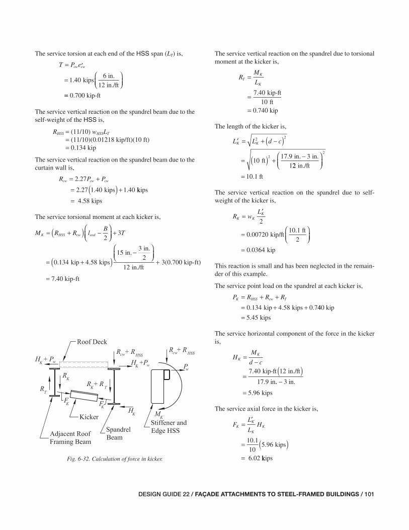
DESIGN GUIDE 22 / FAÇADE ATTACHMENTS TO STEEL-FRAMED BUILDINGS / 101
The service torsion at each end of the HSS span (LT) is,
T P ecw cw=
=⎛⎝⎜
⎞⎠⎟
′
. kips6 in.
12 in./ft1 40
== 0 70. 0 kip-ft
The service vertical reaction on the spandrel beam due to the self-weight of the HSS is,
RHSS = (11/10) wHSSLT
= (11/10)(0.01218 kip/ft)(10 ft) = 0.134 kip
The service vertical reaction on the spandrel beam due to the curtain wall is,
R P Pcw cw cw= +
= ( ) +
2 27
2 27 1 40 1 40
.
. . .kips kkips
4.58 kips=
The service torsional moment at each kicker is,
( )M R R lB
TK HSS cw eod= + −⎛⎝⎜
⎞⎠⎟
+2
3
=
= 7.40 kip-ft
0 134 3(0.700 kip-ft)ki. p kips
in.in.
in./ft+( )
−⎛⎝⎜
⎞⎠⎟
+4.58
153
2
12
The service vertical reaction on the spandrel due to torsional moment at the kicker is,
RM
LT
K
K
=
=
=
kip-ft
ft0 kip
7 40
100 74
.
.
The length of the kicker is,
′ = + −( )
= ( ) + −
L L d cK K2 2
210
17 9 3
1ft
in. in..
22
10 1
2
in./ft
ft
⎛⎝⎜
⎞⎠⎟
= .
The service vertical reaction on the spandrel due to self-weight of the kicker is,
R wL
K KK=′
=⎛⎝⎜
⎞⎠⎟
2
0 00720 kip/ft10.1 ft
2.
kip= 0 0364.
This reaction is small and has been neglected in the remain-der of this example.
The service point load on the spandrel at each kicker is,
P R R RK HSS cw T= + += + +kip kips 0.70 134 4 58. . 440 kip
kips= 5 45.
The service horizontal component of the force in the kicker is,
HM
d cK
K=−
=( )kip-ft in./ft
17.9 in
7 40 12.
.. − 3 in.
kips= 5 96.
The service axial force in the kicker is,
FL
LHK
K
K
K=
= ( )=
′
.. kips
6.02
10 1
105 96
kkipsFig. 6-32. Calculation of force in kicker.
071-114_DG22_Ch06.indd 101 7/16/08 4:46:06 PM
102 / FAÇADE ATTACHMENTS TO STEEL-FRAMED BUILDINGS / DESIGN GUIDE 22
The required kicker axial strength is,
F FuK K=
= ( )=
1 2.
1.2 6.02 kips
7.22 kiips
From AISC Manual Table 4-12, the available axial compres-sion strength of the single angle, assume that the kicker has an effective length factor of K = 1.0 with the ends pinned is,
φcPn = 9.82 kips > FuK o.k.
The defl ection of the assembly at the center of the span is calculated as the vertical defl ection at the HSS midspan as-suming that it is simply supported at each kicker. The de-fl ection at the center of the HSS span with point loads at one-third points of the span is derived from AISC Manual Table 3-23, case 9.
ΔHSScw T
x
HSS T
x
P L
EI
w L
EI= +
=
3 4
28
5
384
1 40. kips ft in./ft
ksi
( )( ) ( )( )
10 12
28 29 000 10
3 3
, ..
.
7
5 0 01218 10 124
in.
kip/ft ft in./f
4( )+
( )( ) tt
ksi in.4
( )( )( )
=
3
384 29 000 10 7
0 28
, .
. 77 in.
Torsional rotation of the HSS at midspan is,
θHSS
TTL
GJ=
⎛⎝⎜
⎞⎠⎟
=
⎛
3
0 70010
3kip-ft
ft.
⎝⎝⎜⎞⎠⎟
( )( )
12 in./ft
ksi in.
2
411 200 11 0, .
rad. (or 0.156= °0 00273. )
The vertical displacement of the HSS due to rotation of the HSS between kickers at midspan is,
ΔHSS HSS
Bθ θ=
=⎛⎝⎜
⎞2
0 00273 rad.3 in.
2.
⎠⎠⎟
⎛⎝⎜
⎞⎠⎠⎟
= in.0 00409.
This defl ection is small and has been neglected in the rest of this example.
The vertical defl ection of the spandrel beam at the kicker (reduced from the AISC Manual Table 3-23, cases 1 and 9) is,
ΔsK
x
D S
x
P L
EI
w w L
EI= +
+( )
=
= 0.565 in.
5
162
22
1 944
5 5 4
3 4
,
. 55 30 12
162 29 000
3 3kips ft in./ft
ksi
( )( ) ( )( )
( ), 8800 in.
kip/ft kip
4( )+
+22 0 144 0 188. . //ft (30 ft) (12 in./ft)1,944(29,000 ksi)(800 in. )4
4 3
The axial shortening of the kicker due to the compression load is,
ΔKK K
K
F L
A E′
′
.
=
=( )kips 10.1 ft in./f6 02 12 tt
2.09 in. ksi
in.
2
( )( )
=
29 000
0 0120
,
.
This defl ection is small and has been neglected in the rest of this example.
The service wind point load transmitted to the roof deck at the stiffener is calculated using the reaction at an interior support of a three span beam (AISC Manual, Table 3-22c),
P = ph
= . .
wind w11
10
1 1 0 030
2
kip/
⎛⎝⎜
⎞⎠⎟
LT
fftft
2ft
= 2.31 kip
2( )⎛⎝⎜
⎞⎠⎟
( )1410
ss
Based on how much deck is tributary to each kicker, the ef-fective width of the metal roof deck is,
beff = 3 ft
The horizontal elongation of the metal roof deck is,
ΔD
K wind deck
eff deck
H P s
b t E=
+( )
=5.96 kips + 2.31 kips 10 ft
3 ft 0.0358 in. 29,00
( )( )( ) 00 ksi
in.
( )= 0 0266.
071-114_DG22_Ch06.indd 102 7/16/08 4:46:07 PM
DESIGN GUIDE 22 / FAÇADE ATTACHMENTS TO STEEL-FRAMED BUILDINGS / 103
Using ΔD as the lateral translation of the top fl ange of the spandrel beam, the rotation of the spandrel beam at the kicker due to load in the roof deck is,
θKD
d=
=
=
Δ
in.
18.0 in.r
0 0266
0 00149
.
. aad. (or 0.0850°)
The rigid body translation of the corner of the HSS due to rotation of the kicker assuming small angle rotation (where θ = sin θ) is,
ΔK K eodl=
= ( )=
θ
rad. in.0 00149 15
0
.
..0224 in.
Both ΔD and ΔK are small and will be neglected.
From Example 6.1, the vertical defl ection is limited to 0.90 in. The total vertical displacement of the HSS at the center of its span is,
Δ Δ Δtotal HSS s= += +in. in.0 287 0 565. .
in. 0.90 in.= ≤0 852. o.k.
For the welds from the roof deck to the spandrel beam and adjacent beams, try seven deck-to-beam puddle welds within the deck effective width (nweld = 7). Note that this is more welding than the typical deck perimeter attachment. The weld size is dweld = s in.
The factored shear per weld is,
VH P
nuw
K wind
weld
=+
=( )
1 2 0 8
1 2 5 96
. .
. . kips ++
=
0 8 2 31
71 29
. ( .
.
kips)
kips
The weld shear strength in accordance with the Steel Deck Institute Diaphragm Design Manual (SDI, 2004), page 4-4 is,
φ == −( )
0 70
2 2
.
.Q t F d tf deck u weld deck
in. ksi in.= ( )( ) −2 2 0 0358 45 0 625 0 0358. . . . iin.
kips
kips
( )== ( )
2 09
0 70 2 09
.
. .φQf
kips >= 1 46. Vuw
Seven puddle welds between the roof deck and the span-drel beam within a 3-ft width adjacent to the stiffeners and kickers will carry the forces from torsion and wind loads from the curtain wall into the roof deck. The same number of welds is also required at the adjacent roof framing beam (the fi rst interior beam). The design of the stiffener plate was illustrated in Example 6.3.
Comments:
The edge HSS allows for a substantial eccentricity between the cladding and the spandrel framing without a substantial penalty on the weight of the framing. In this example, using kickers in place of slightly heavier roll beams has reduced the steel tonnage. However, the kickers require additional puddle welds between the roof deck and the spandrel and ad-jacent roof framing beams than might otherwise be required. The connections between the kicker and the adjacent beams are most often fi eld-welded and these welds can add some cost to the project. The best choice between these various options depends upon fi nding the right mix of material costs and labor costs. Thus, it is ideal to discuss the options with the steel fabricator to determine which one will provide the least total cost.
Example 6.5—Floor Spandrel Beam with Eccentric Precast Panel Loads
The 30-ft-long spandrel beam shown in Figures 6-33 and 6-34 supports the fl oor framing shown in addition to 6-in.-thick precast concrete cladding panels weighing 75 psf. The pan-els are supported by steel brackets bearing on each fl oor slab 2 in. from the edge of the slab. The 64-in.-thick fl oor system consists of 34 in. of 3,000 psi lightweight concrete on 3-in. metal fl oor deck. The fl oor live load is 100 psf, and the super-imposed (post-composite) dead load is 15 psf. The maximum vertical defl ection due to superimposed loads is 2 in.
Design a bearing connection for the precast panel by evaluating the slab for fl exural loads induced by the precast cladding. If the slab cannot resist the fl exural loads, evaluate whether the bent-plate pour stop is capable of resisting the fl exural loads.
Determine the total vertical defl ection at the support points for the precast panels. Also, determine the adequacy of the spandrel beam including the effects of normal stresses due to torsional warping.
Given:
For this example assume the controlling load combination for strength is 1.2D + 1.6S + 0.8W (D + S + W for defl ection). The fl oor framing beams perpendicular to the spandrel pro-vide some torsional restraint for the spandrel. The contribu-tion of the composite fl oor system to the torsional stiffness of the spandrel is conservatively ignored. The horizontal
071-114_DG22_Ch06.indd 103 7/16/08 4:46:07 PM

104 / FAÇADE ATTACHMENTS TO STEEL-FRAMED BUILDINGS / DESIGN GUIDE 22
eccentricity between the centroid of the precast panel and the edge of the pour stop is resolved by a couple between adjacent fl oors.
The spandrel beam is a W24×76 with a length of L = 30 ft for fl exure and a length of LT = 10 ft for torsion. The span of the perpendicular fl oor framing beams is Lfb = 25 ft with the spacing of the supports for the precast panels at sp = 10 ft.
The post-composite properties of the spandrel beam are, Seff = 217 in.3 and Ieff = 3,410 in.4 The pre-composite factored moment demand Mpre = 93.0 kip-ft (with a load
factor of 1.2) with a total factored moment demand Mu = 414 kip-ft. The post-composite defl ection of the spandrel beam due to live load and superimposed dead load at mid-span is 0.377 in.
The story height is h = 12 ft, with the eccentricity between the point of precast load and the centerline of the beam, e = 8 in. The horizontal eccentricity between the point of the precast load and the centerline of the precast panels, ep = 6 in. The vertical eccentricity between the bottom fl ange of the spandrel beam and the point of horizontal panel load, er = 22 in.
The width of the precast embed parallel to the slab edge, bpc = 3 in.
The W24×76 spandrel beam has the following properties:
d = 23.9 in. bf = 8.99 in. tf = 0.680 in.
Iy = 82.5 in.4
Sx = 176 in.3
Sy = 18.4 in.3
J = 2.68 in.4
a = 104 in. Wno = 52.2 in.2
The W14×22 fl oor framing beams have Ix = 199 in.4
The pour stop plate is made from ASTM A36 material.
Solution:
For the loads on the spandrel beam, see Figures 6-35, 6-36, and 6-37. The service precast panel point load at each sup-port point on the spandrel is,
P hspc p= ( )= ( )
0 075. kip/ft
0.075 kip/ft
2
2 112 ft 10 ft
9.00 kips
( )( )=
The factored precast panel point load at each support point on the spandrel beam is,
P Pupc pc=
= ( )=
1 2.
1.2 9.00 kips
10.8 kiips
The service wind point load on the spandrel beam at each precast panel support point location is,
P p s hw w p=
= ( )( )kip/ft 10 ft ft20 030 12.
kips= 3 60.
Fig. 6-33. Section of fl oor spandrel beam with precast panel supported on slab.
Fig. 6-34. Floor plan at spandrel beam.
071-114_DG22_Ch06.indd 104 7/16/08 4:46:07 PM

DESIGN GUIDE 22 / FAÇADE ATTACHMENTS TO STEEL-FRAMED BUILDINGS / 105
The factored wind point load at each precast panel support point on the spandrel is,
P Puw w=
= ( )=
0 8
0 8 3 60
2 88
.
. .
.
kips
kipss
The service horizontal force on the spandrel beam due to eccentricity of the panel with respect to the pour stop is,
PP e
h d eH
pc p
r
=− −
=( )kips in.
ft 12
9 00 6
12
.
iin./ft in. in.
kip
( ) − −
=
23 9 2 5
0 459
. .
.
The factored horizontal force on the spandrel beam due to eccentricity of the panel with respect to the pour stop is,
( )P PuH H=
= ( )=
1 2
1 2 0 459
0 551
.
. .
.
kip
kipp
For the design of the bearing support for the precast panel, the slab strength to support the gravity load of the precast panel will be evaluated assuming that the panel load spreads over an effective width at 45° to each side.
The effective width of the slab to resist the precast load is,
= °b eb
beff
f
pc−⎛
⎝⎜
⎞
⎠⎟ +
= °
2 452
2 45 8
tan
tan in..in.
in.
in.
−⎛⎝⎜
⎞⎠⎟
+
=
8 99
23
10 0
.
.
The factored moment in the slab due to the precast gravity load is,
= −M P eb b
bus upc
f
eff
⎛
⎝⎜
⎞
⎠⎟
=
2
10 8 8kips in.. −−⎛⎝⎜
⎞⎠⎟
=
8 99
2
12
10 0
45 4
.
.
.
in. in./ft
in.
kip-in./ft
Fig. 6-37. Vertical and lateral forces on spandrel beam.
Fig. 6-35. Loads on spandrel beam.
Fig. 6-36. Resolution of precast panel eccentricity.
071-114_DG22_Ch06.indd 105 7/16/08 4:46:08 PM

106 / FAÇADE ATTACHMENTS TO STEEL-FRAMED BUILDINGS / DESIGN GUIDE 22
From Table 5-4, it will be diffi cult to provide enough re-inforcement in the slab to resist the fl exure created by the panel load. As an alternative, determine if the bent plate can resist all fl exure induced by the precast panels (see Figure 6-38). The horizontal force is resisted by the studs in ten-sion and developed into the slab through the slab reinforcing steel. For fl exure, AISC Specifi cation Section F11 provides the fl exural strength of rectangular bars bent about the minor axis.
Try a 2-in.-thick bent plate where the effective width of the plate tributary to the precast attachment, assuming the load spreads at 45° to each side, is,
b e= °b
beff
f
pc−⎛
⎝⎜
⎞
⎠⎟ +
= °
2 452
2 45 8
tan
tan in..in.
in.
in.
−⎛⎝⎜
⎞⎠⎟
+
=
8 99
23
10 0
.
.
The moment on the plate is,
M Mup us= = 45 4. kip-in./ft
The plastic section modulus of the plate per foot is,
Zbt
p =
=( )
=
2
2
4
12 0 5
40 750
in./ft in..
. in. /ft3
The available fl exural strength of the bent plate is,
φ φM F Znp y p=
= (ksi) 0.750 in. /ft30 90 36. ( ))= <kip-in./ft24 3. Mus n.g.
The precast panel loads are too large for a reasonable thickness bent plate to cantilever off of the spandrel beam fl ange. The 2-in. plate alone does not have adequate fl exural strength. Additionally, as shown below, the defl ection of the plate (which combines with the defl ection of the spandrel) is excessive.
The distance between welds connecting the plate to the beam fl ange is,
sweld = 2 in.
The effective moment of inertia of the plate is,
Ib teff
=
=( )
=
3
3
12
10 0
120 104
in. 0.50 in.
in
.
. ..4
The vertical defl ection of the end of the plate, neglecting the weight of the concrete (from AISC Manual Table 3-23, case 26), is,
ΔV
pc
weld
P e
EIe s= +( )
=( )
2
2
3
9 00 kips 8 in..
33 29 000 0 1048 2
, .ksi inin. in.
4( )( ) +( )= 00 637. in.
Therefore, stiffener plates must be added to the spandrel at each precast panel support point and the spandrel designed to take torsion. See Figure 6-39. Adding the stiffeners elimi-nates the need to design the bent plate pour stop for any loads other than the wet load of the concrete. From Table 5-11, a 2-in.-thick bent plate pour stop will be suffi cient.
For the purposes of the analysis, consider the spandrel beam restrained for torsion at each of the perpendicular fl oor framing beams and the columns. Use the provisions from AISC Design Guide No. 9 to determine the maximum angle of twist. Assume the rotation is about the center of the top fl ange of the spandrel beam since it is restrained by the con-crete slab.
Fig. 6-38. Defl ection of bent plate pour stop.
071-114_DG22_Ch06.indd 106 7/16/08 4:46:08 PM

DESIGN GUIDE 22 / FAÇADE ATTACHMENTS TO STEEL-FRAMED BUILDINGS / 107
The service torsional moment at the midspan of LT due to the precast load is,
T P e P d epc pc H r= − +( )=
( ) −kips 8 in.9 00 0 4. . 559 23 9 2
12
4 99
kip in. in.
in./ft
.
.
+( )
=
2
kip-ft
The service torsional moment at the midspan of LT due to the wind load applied at the bottom of the beam is,
TP (d )w
w=
=
⎛⎝⎜
⎞⎠⎟
( )23 60
223 9
12
..
kipsin.
in./ft
kip-ft= 3 59.
The total service torsional moment applied at the midspan of LT is,
T T Tpc w= +
= +=
kip-ft kip-ft4 99 3.59
8 58
.
. kkip-ft
The service torsion at each end of LT is,
TT
e =
=
=
28 58
24 29
kip-ft
kip-ft
.
.
To obtain the service moment applied to the ends of the fl oor-framing beams, multiply Te by 2 because the precast panels are symmetric about the fl oor framing beams. The service moment applied to the end of the fl oor framing beam is,
M Tfb e=
= ( )=
2
2 4 29
8 58
kip-ft
kip
.
. --ft
The rotation at the end of the fl oor framing beam (see Figure 6-40) is,
θ fb
fb fb
x fb
M L
EI=
=( )
3
8 58 12kip-ft 25 ft in. ../ft
ksi in.4
( )( )( )
=
2
3 29 000 199
0 00178
,
. rad. (or 0.102°)
The service vertical reaction on the spandrel beam due to the end moment on the fl oor framing beam is,
RM
Lfb
fb
fb
=
=
=
kip-ft
25 ft
8 58
0 343
.
. kip
In this case, Rfb is small. In many practical cases it may be neglected.
L
aT = ( ) =10
1 15ft
104 in./ 12in./ft.
From AISC Design Guide No. 9, Appendix B, case 3 for α = 0.5, the torsional function at the center of the span LT
(between roll beams) is,
θ GJ
TLT
⎛
⎝⎜⎞
⎠⎟= 0 025. rad.
Fig. 6-39. Section of spandrel beam with stiffener plate at bottom fl ange connection to precast panel. Fig. 6-40. Rotation of roll beam.
071-114_DG22_Ch06.indd 107 7/16/08 4:46:09 PM

108 / FAÇADE ATTACHMENTS TO STEEL-FRAMED BUILDINGS / DESIGN GUIDE 22
θuuT
GJa″
.
. .
=
=( )
0 25
0 25 8 86 12kip-ft in./fft
ksi in. in.4
( )( )( )( )
=
11 200 2 68 104
8
, .
..51 10 6× − rad./in.2
The normal stress at midspan due to warping is,
σ θwsu no uEW=
= ( )″
, ksi 52.2 in.229 000 8..
.
51 10
12 9
6×( )=
− rad./in.
ksi
2
The factored post composite moment demand is,
= −M M Mpost u pre
= −kip-ft kip-f414 93 0. tt
kip-ft= 321
The interaction of combined normal stresses at the midspan of the beam is based on the AISC Design Guide No. 9, Equa-tion 4.16a, using the elastic combination of stresses,
= +σ σtotal
pre
x
post
effwsu
M
S
M
S+
=kip-93 fft 12 in./ft
in.kip-ft 12 in./ft
3
( )
+(
176321 ))
+
=
=
21712 9
37 0in.
ksi
ksi
0
3.
.
φFy ..90
0.90 50 ksi
k
Fy
= ( )= 45 0. ssi > 37.0 ksi o.k.
The beam has adequate fl exural strength.
Comments:
As an alternative approach, the rotation of the beam can be determined using the “Flexural Analogy,” which converts the applied torsion into a couple acting at the top and bottom fl anges of the beam. The force at the top fl ange is assumed to be resisted by the slab. The force at the bottom fl ange is assumed to be resisted by weak-axis bending of the bottom half of the W24. The calculated defl ection is then converted into an equivalent rotation about the top fl ange.
The rotation at the center of the span, LT, is,
θ =
=( )(
( rad.)
rad. kip-ft
0 025
0 025 8 58
.
. .
TL
GJT
))( )( )( )( )
10 12
11 200 2 68
2ft in./ft
ksi in.4, .
rad. (or 0.585 )= °0 0102.
Note that this torsional rotation θ assumes the spandrel beam can rotate about its centroid. In reality, the spandrel beam is restrained by the slab and will rotate about the center of its top fl ange. Thus, the actual rotation will be slightly smaller.
Adding the rotation of the spandrel beam between the roll beams to the rotation of the roll beams,
θ θ θtotal f b= +
= ° + °=
0 585 0 102
0
. .
.6687°
The vertical defl ection at the precast support point due to rigid body rotation,
( )Δvrb totale=
= ( ) °
sin
sin ( . )
θ
in.8 0 687
in.= 0 0959.
The total vertical defl ection is,
Δtotal = Δvrb + Δpcl
= 0.0959 in. + 0.377 in.
= 0.473 in. ≤ 2 in. o.k.
The available strength of the spandrel beam is calculated us-ing case 3 from AISC Design Guide No. 9, Appendix B to determine the normal stresses due to warping. The factored torsional moment at the middle of the torsion span is,
T T Tu pc w= +
= ( ) +
1 2 0 8
1 2 4 99 0 8 3 59
. .
. . . .kip-ft kip-ft
kip-ft
( )= 8 86.
The torsional function at the center of the span LT (between roll beams) is,
″
⎛
⎝⎜⎞
⎠⎟=θu
u
GJa
T0 25.
071-114_DG22_Ch06.indd 108 7/16/08 4:46:09 PM
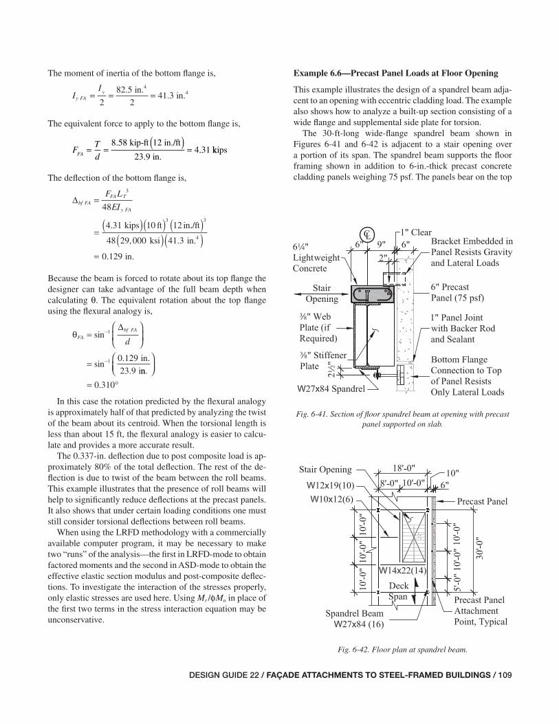
DESIGN GUIDE 22 / FAÇADE ATTACHMENTS TO STEEL-FRAMED BUILDINGS / 109
Example 6.6—Precast Panel Loads at Floor Opening
This example illustrates the design of a spandrel beam adja-cent to an opening with eccentric cladding load. The example also shows how to analyze a built-up section consisting of a wide fl ange and supplemental side plate for torsion.
The 30-ft-long wide-fl ange spandrel beam shown in Figures 6-41 and 6-42 is adjacent to a stair opening over a portion of its span. The spandrel beam supports the fl oor framing shown in addition to 6-in.-thick precast concrete cladding panels weighing 75 psf. The panels bear on the top
The moment of inertia of the bottom fl ange is,
I
Iy FA
y4
4in.in.= = =
2
82 5
241 3
..
The equivalent force to apply to the bottom fl ange is,
F
T
dFA= =
( )=
8.58 kip-ft 12 in./ft
23.9 in.4 31. kkips
The defl ection of the bottom fl ange is,
Δbf FAFA T
y FA
F L
EI=
=( )( )
3
3
48
4 31 10 12kips ft in. ../ft
ksi in.
in.
( )( )( )
=
3
448 29 000 41 3
0 129
, .
.
Because the beam is forced to rotate about its top fl ange the designer can take advantage of the full beam depth when calculating θ. The equivalent rotation about the top fl ange using the fl exural analogy is,
θFA
bf FA
d=
⎛
⎝⎜
⎞
⎠⎟
=
−
−
sin
sin.
.
1
1 0 129
23 9
Δ
in.
inn.
⎛⎝⎜
⎞⎠⎟
= °0 310.
In this case the rotation predicted by the fl exural analogy is approximately half of that predicted by analyzing the twist of the beam about its centroid. When the torsional length is less than about 15 ft, the fl exural analogy is easier to calcu-late and provides a more accurate result.
The 0.337-in. defl ection due to post composite load is ap-proximately 80% of the total defl ection. The rest of the de-fl ection is due to twist of the beam between the roll beams. This example illustrates that the presence of roll beams will help to signifi cantly reduce defl ections at the precast panels. It also shows that under certain loading conditions one must still consider torsional defl ections between roll beams.
When using the LRFD methodology with a commercially available computer program, it may be necessary to make two “runs” of the analysis—the fi rst in LRFD-mode to obtain factored moments and the second in ASD-mode to obtain the effective elastic section modulus and post-composite defl ec-tions. To investigate the interaction of the stresses properly, only elastic stresses are used here. Using Mr /φMn in place of the fi rst two terms in the stress interaction equation may be unconservative.
Fig. 6-41. Section of fl oor spandrel beam at opening with precast panel supported on slab.
Fig. 6-42. Floor plan at spandrel beam.
071-114_DG22_Ch06.indd 109 7/16/08 4:46:09 PM

110 / FAÇADE ATTACHMENTS TO STEEL-FRAMED BUILDINGS / DESIGN GUIDE 22
Ix = 2,850 in.4
Iy = 106 in.4
Sy = 21.2 in.3
Zy = 33.2 in.3
J = 2.81 in.4
a = 128 in.
The defl ection due to superimposed dead load at midspan is Δpcl = 0.48 in.
The W14×22 fl oor framing beam has Ix = 199 in.4
of the slab 2 in. from the edge of the slab. The 64-in.-thick fl oor system consists of 34-in. lightweight concrete on 3-in. metal fl oor deck. The fl oor live load is 100 psf, and the su-perimposed dead load is 15 psf. The maximum vertical de-fl ection due to superimposed loads is 2 in.
Determine the total vertical defl ection at the support points for the precast panels considering torsion and the bare W27 section. If the defl ection of the bare W27 section is exces-sive, add a second web to create a built-up box section to increase torsional stiffness. Check the strength and the hori-zontal displacement of the spandrel beam—for this case, use a horizontal defl ection limit of L/480.
Given:
For this example assume the controlling load combination for strength is 1.2D + 1.6S + 0.8W (D + S + W for defl ec-tion). The spandrel beam is a W27×84, while the W14×22 fl oor framing beam perpendicular to the spandrel provides torsional restraint for the spandrel. For the spandrel beam, L = 30 ft for fl exure and LT = 20 ft for torsion. The length of the W14×22 fl oor beam, Lf b = 10 ft. The story height, h = 12 ft.
The horizontal eccentricity between the centroid of the precast panel and the edge of the pour stop is resolved by a couple between adjacent fl oors. The pour stop is a 4-in.-thick bent plate. The spandrel has web stiffeners at the pre-cast attachment locations. Because of the opening, assume that the spandrel beam does not act compositely with the fl oor slab. The spandrel beam defl ects a total of 0.48 in. due to live loads and superimposed dead loads, including the cladding.
The supports for the precast panels are spaced at sp = 10 ft apart. The horizontal eccentricity between the point of the precast panel attachment and the centerline of the beam, e = 7 in. The horizontal eccentricity between the point of the precast panel attachment and centerline of the precast panels is ep = 6 in. The vertical eccentricity between the bottom fl ange of the spandrel beam and the panel attachment point is er = 22 in. Any additional contribution of the concrete slab strip to the torsional constant, J, of the section has been neglected.
The factored moment demand, Mu = 414 kip-ft. The avail-able moment strength of the bare beam, considering a later-ally unbraced length Lb = 20 ft, is φbMn = 579 kip-ft, based on AISC Manual Table 3-10.
For the loads on the spandrel beam, see Figures 6-43, 6-44 and 6-45. The W27×84 spandrel beam has the follow-ing properties:
d = 26.7 in. tw = 0.460 in. bf = 10.0 in. tf = 0.640 in.
Fig. 6-43. Loads on spandrel beam.
Fig. 6-44. Resolution of precast panel eccentricity.
071-114_DG22_Ch06.indd 110 7/16/08 4:46:10 PM
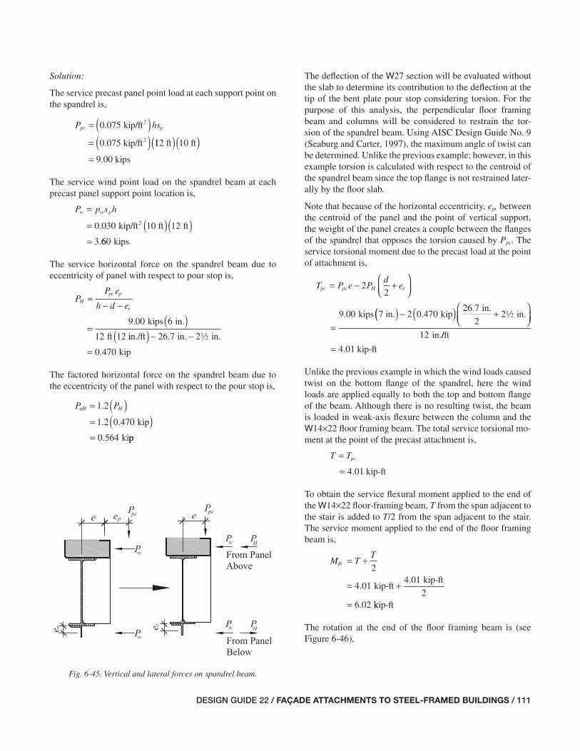
DESIGN GUIDE 22 / FAÇADE ATTACHMENTS TO STEEL-FRAMED BUILDINGS / 111
The defl ection of the W27 section will be evaluated without the slab to determine its contribution to the defl ection at the tip of the bent plate pour stop considering torsion. For the purpose of this analysis, the perpendicular fl oor framing beam and columns will be considered to restrain the tor-sion of the spandrel beam. Using AISC Design Guide No. 9 (Seaburg and Carter, 1997), the maximum angle of twist can be determined. Unlike the previous example; however, in this example torsion is calculated with respect to the centroid of the spandrel beam since the top fl ange is not restrained later-ally by the fl oor slab.
Note that because of the horizontal eccentricity, ep, between the centroid of the panel and the point of vertical support, the weight of the panel creates a couple between the fl anges of the spandrel that opposes the torsion caused by Ppc. The service torsional moment due to the precast load at the point of attachment is,
T P e Pd
epc pc H r= − +⎛⎝⎜
⎞⎠⎟
=
22
9 00 kips 7 in.. (( ) − ( ) +⎛⎝⎜
⎞⎠⎟
2 0 47026 7
22
12
..
kipin.
in.
in.
2
//ft
kip-ft= 4 01.
Unlike the previous example in which the wind loads caused twist on the bottom fl ange of the spandrel, here the wind loads are applied equally to both the top and bottom fl ange of the beam. Although there is no resulting twist, the beam is loaded in weak-axis fl exure between the column and the W14×22 fl oor framing beam. The total service torsional mo-ment at the point of the precast attachment is,
T Tpc=
= 4 01. kip-ft
To obtain the service fl exural moment applied to the end of the W14×22 fl oor-framing beam, T from the span adjacent to the stair is added to T/2 from the span adjacent to the stair. The service moment applied to the end of the fl oor framing beam is,
M TT
fb = +
= +
=
2
4 014 01
26 02
..
.
kip-ftkip-ft
kkip-ft
The rotation at the end of the fl oor framing beam is (see Figure 6-46),
Solution:
The service precast panel point load at each support point on the spandrel is,
( )P hspc p=
= ( )0 075. kip/ft
0.075 kip/ft
2
2 112 ft 10 ft
9.00 kips
( )( )=
The service wind point load on the spandrel beam at each precast panel support point location is,
P p s hw w p=
= ( )( )=
0 030 12
3
.
.
kip/ft 10 ft ft2
660 kips
The service horizontal force on the spandrel beam due to eccentricity of panel with respect to pour stop is,
PP e
h d eH
pc p
r
=− −
=( )kips in.
ft 12
9 00 6
12
.
iin./ft in. in.
kip
( ) − −
=
26 7 2
0 470
.
.
2
The factored horizontal force on the spandrel beam due to the eccentricity of the panel with respect to the pour stop is,
( )P PuH H=
= ( )=
1 2
1 2 0 470
0 564
.
. .
.
kip
kipp
Fig. 6-45. Vertical and lateral forces on spandrel beam.
071-114_DG22_Ch06.indd 111 7/16/08 4:46:10 PM

112 / FAÇADE ATTACHMENTS TO STEEL-FRAMED BUILDINGS / DESIGN GUIDE 22
θ =
=( )( )
( rad.)0 040
0 040
.
.
TL
GJT
rad. 4.01 kip-ft 220 12
11 200 2 81
2ft in./ft
ksi in.4
( )( )( )( ), .
rad. (or 0.841= °0 0147. )
To obtain the total rotation at midspan due to two point loads superimposed,
θ θtotal =
= °( )= °
2
2 0 841
1 68
.
.
The vertical defl ection at the tip of the pour stop due to rigid body rotation is,
( )Δvrb totale=
= ( ) °
=
sin
sin( . )
θ
7 1 68
0
in.
..205 in.
The total vertical defl ection at the center of the opening is,
Δ total = Δvrb + Δpcl = 0.205 in. + 0.48 in. = 0.685 in. ≥ 2 in. n.g.
Because the defl ection exceeds the established limit, con-sider adding a second web to the W27×84 to create a box section, which will have substantially more torsional stiff-ness. Try a a-in.-thick plate to the side of the beam toward the opening.
The torsional constant, J, of the closed section, neglecting the outer fl anges of the W27× 84, can be calculated using AISC Design Guide No. 9, Table 3.1. The distance from the center-line of the spandrel beam to the centerline of the plate is,
= −bb t t
bf w p+
= − +
2 2 210 0
2
0 460
2
in. in. in. . a ..
in.2
4 96= .
The centerline-to-centerline height of the box section is,
hb = d – tf = 26.7 in. – 0.640 in. = 26.1 in.
The least thickness of the web and plate can be used to determine J.
t t twb p w=
==
min( , )
min( , . )in. in.a
a
0 460
in.
θ fb
fb fb
xfb
M L
EI=
=( )
3
6 02 12. kip-ft 10 ft in./ftt
ksi in.
r
4
( )( )( )
=
2
3 29 000 199
0 000501
,
. aad. (or 0.0287°)
This rotation is very small and has been neglected in subse-quent calculations.
The service vertical reaction on the spandrel due to the end moment on the fl oor framing beam is,
RM
Lfb
fb
fb
=
=
=
6 02
0 602
.
.
kip-ft
10 ftkip
This reaction is small and can be ignored for calculations.Assuming that the spandrel beam is restrained for torsion
at each end of the fl oor opening, the spandrel beam defl ec-tion can be calculated as follows using AISC Design Guide No. 9, Appendix B, case 3. The torsional constant, J, for the bare steel beam is used, neglecting any additional contribu-tion of the concrete slab strip. Note that this case does not provide values for two torques applied at the one-quarter points of the span. Therefore, superposition will be used to determine the rotation at the midspan of the opening. Inter-polating between the charts for α = 0.1 and α = 0.3, the rota-tion at midspan due to a single point load at α = 0.25 is,
L
aT =
( )=
201 88
ft 12in./ft
128 in..
θ GJ
TLT
⎛
⎝⎜⎞
⎠⎟= 0 040. rad.
Fig. 6-46. Rotation of roll beam.
071-114_DG22_Ch06.indd 112 7/16/08 4:46:11 PM
DESIGN GUIDE 22 / FAÇADE ATTACHMENTS TO STEEL-FRAMED BUILDINGS / 113
Δhw T
yb
P L
EI=
=( )( )
11
384
11 3 60 20 12
3
3. kips ft inn./ft
ksi in.4
( )( )( )
=
3
384 29 000 296
0 16
,
. 66 in. /480≤ LT o.k.
This calculation assumes that the beam is simply supported at each end of the fl oor opening. Because the beam is con-tinuous past the W14 fl oor framing beam at the edge of the opening, the calculation is conservative. If a less conserva-tive solution is desired, the continuity can be considered.
To check the strength of the spandrel beam, with the second web plate the W27×84 can be considered as a box section, neglecting warping normal stresses as described in AISC Design Guide No. 9. For simplicity in checking weak-axis fl exure, the spandrel beam will be assumed as simply supported between the column and the W14×22 fl oor fram-ing beam. The a-in.-thick web plate will also be neglected for strength. The factored wind point load at each precast panel support point on the spandrel is,
P Puw w=
= ( )=
0 8
0 8 3 60
2 88
.
. .
.
kips
kips
The required weak-axis fl exural strength on the spandrel beam between supports is,
MP L
uyuw T=
=( )
=
32 88
319 2
.
.
kips 20 ft
kipp-ft
The required torsional strength is,
T Tu =
= ( )=
1 2
1 2 4 01
4 81
.
. .
.
kip-ft
kip-ft
The available torsional strength of the built-up box section can be calculated assuming that the section is comprised en-tirely of ASTM A572 Grade 50 plate material (Fy = 50 ksi) except when calculating slenderness ratios (a conservative lower bound). The box width-thickness ratio is as follows,
h
tw
= =26 1
0 37569 6
.
..
in.
in.
The torsional constant, J, of the box section is,
Jt t b h
b t h t
f wb b b
b wb b f
=+
=( )(
2
2 0 640
2 2
. in. in.a ))( ) ( )( ) +
4 96 26 1
4 96 26
2 2. .
. .
in. in.
in. in.a 11 0 640
433
in. in.
in.4
( )( )=
.
The maximum rotation of the box section will occur at the point of the precast attachment. The rotation of the beam will be constant between the points of applied torque. The torsional rotation of the box section is,
θb
TTL
GJ=
⎛⎝⎜
⎞⎠⎟
=
⎛⎝⎜
⎞⎠⎟
4
4 0120
412. kip-ft
ftftt/in.
ksi in.4
( )( )
=
2
11 200 433
0 000595
,
. rrad. (or 0.0341°)
The vertical defl ection at the tip of the pour stop due to the rigid body rotation is,
( )Δvrb be=
= ( ) °
=
sin
sin( . )
.
θ
7 0 0341
0 0
in.
00417 in.
Neglecting the contribution of the second web plate to the fl exural stiffness of the section, the total defl ection at the center of the slab opening is,
Δ Δ Δtotal vrb pcl= +
= +0 00417. in. 0.48 in.
in. in.= ≤0 484. 2 o.k.
To check the lateral (out-of-plane) defl ection of the span-drel beam, the spandrel can be assumed as pinned for out-of-plane fl exure at the ends of the opening. The weak-axis moment of inertia of the built-up section is,
Iyb = 296 in.4
The defl ection limit was selected as,
LT
480
20 12
480=
=
ft in./ft
in.
( )
2
Using the AISC Manual Table 3-23, case 9, with the concen-trated loads at the one-quarter points and simple supports, the out-of-plane defl ection based on the horizontal defl ec-tion at midspan is,
071-114_DG22_Ch06.indd 113 7/16/08 4:46:11 PM

114 / FAÇADE ATTACHMENTS TO STEEL-FRAMED BUILDINGS / DESIGN GUIDE 22
φ φb ny bM F= ≤ φy y b y yZ F S
=( )
1 6
0 90 50
.
. ksii in.
in./ft
ksi
3( )( )
≤( )( )
33.2
12
0.90 1 6 50 21 2. . iin.
in./ft
kip-ft 127 ki
3( )
= ≤12
125 pp-ft
kip-ft= 125
If a more accurate calculation for the weak-axis fl exural strength is necessary, the pour stop plate and a-in.-thick web can be included in the available strength calculations. Because the spandrel has no axial load, AISC Specifi cation Equation H1-1b applies.
+ =M
M
M
Mux
b nx
uy
b nyφ φ+414
579
19 2kip-ft
kip-ft
. kip-ft
kip-ft125
0 870 1 0= ≤. . o.k.
Even considering the conservative nature of this calculation, the section has adequate strength.
Comments:
This example is detailed with a strip of slab on the spandrel beam that has not been counted in the composite action of the slab. The strip of slab is provided to maintain the same edge condition along the entire building. As an alternative solution, it is also permissible to eliminate the slab on the portion of the spandrel beam adjacent to the opening. In this case, the cladding attachment detail would be modifi ed.
Additionally, in this example, the precast cladding panels are supported for gravity loads at 10 ft on center along the spandrel beam. This type of panel arrangement imposes a substantial penalty on the spandrel beam weight because a relatively large moment of inertia is required, particularly because the beam is non-composite. If acceptable to the ar-chitect, the weight of the spandrel would be greatly reduced if the precast panels could span from column to column, as the spandrel beam would not be subject to special defl ection criteria.
A complete design of this spandrel would include a design for the welds between the second web plate and the fl anges, as well as designs for connections at the ends of the spandrel to resist torsion and vertical shear. This is left as an exercise for the reader.
The selection of the appropriate torsional strength equation is based on the following limiting wall slenderness ratios for box sections (from AISC Specifi cation Section H3.1) (AISC, 2005b), based on Fy = 50 ksi for the W27,
λ
λ
py
r
E
F
E
= = =
=
2 45 2 4529 000
5059 0
3 07
. .,
.
.
ksi
ksi
FFy
= =3 0729 000
5073 9.
,.
ksi
ksi
Because 59.0 < h/tw < 73.9, the critical stress for torsion is,
( )F
FE
F
h tcr
yy
w
=
⎛
⎝⎜
⎞
⎠⎟
=( )
0 6 2 45
0 6 50 59
. .
/
. .ksi 00
69 6
( )( )
=
.
25.4 ksi
The box section torsional shear constant, per the AISC Specifi cation Section H3.1 User Note, is,
( )C b h t tb b wb wb= − −
= ( )2 4 5 4
2 4 96 26 1
3.
. .
π
in. inn. in. in.
in.3
( )( ) − −( )( )=
a a4 5 4
96 9
3.
.
π
The available torsional strength is,
φφ φ
T
T n T crT F C
==
=( )(
0 90
0 90 96 9
.
. .25.4 ksi in.3 ))
=12
185
in./ft
kip-ft
The required torsional strength to design torsional strength ratio is,
T
Tu
T nφ= =4 81
1850 0260
..
kip-ft
kip-ft
Because this ratio is less than 20 percent, AISC Specifi ca-tion Section H3.2 permits the use of the equations in AISC Specifi cation Section H1 to evaluate the interaction of fl ex-ural forces. For simplicity, it is conservative to neglect the added fl exural strength of the second web. Refer to AISC Specifi cation Section F6.1, noting that the W27×84 is not susceptible to fl ange local buckling. The available weak-axis fl exural strength is calculated as,
071-114_DG22_Ch06.indd 114 7/16/08 4:46:11 PM
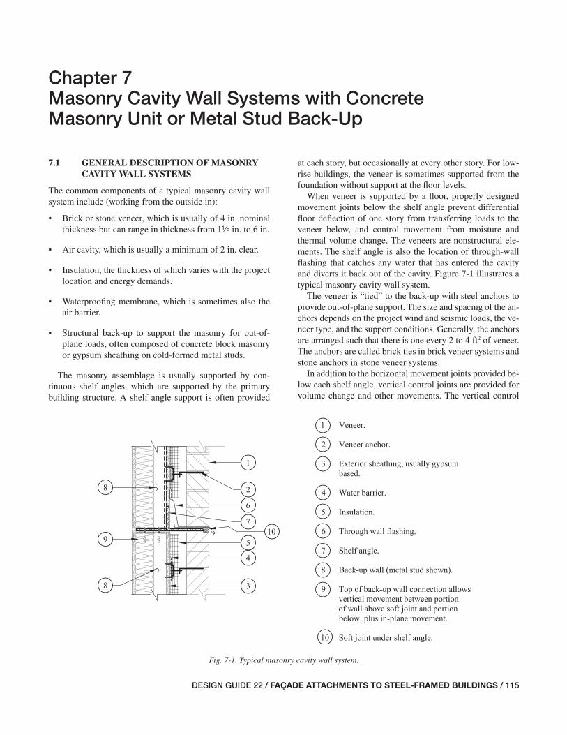
DESIGN GUIDE 22 / FAÇADE ATTACHMENTS TO STEEL-FRAMED BUILDINGS / 115
Chapter 7 Masonry Cavity Wall Systems with Concrete Masonry Unit or Metal Stud Back-Up
7.1 GENERAL DESCRIPTION OF MASONRY CAVITY WALL SYSTEMS
The common components of a typical masonry cavity wall system include (working from the outside in):
• Brick or stone veneer, which is usually of 4 in. nominal thickness but can range in thickness from 1½ in. to 6 in.
• Air cavity, which is usually a minimum of 2 in. clear.
• Insulation, the thickness of which varies with the project location and energy demands.
• Waterproofi ng membrane, which is sometimes also the air barrier.
• Structural back-up to support the masonry for out-of-plane loads, often composed of concrete block masonry or gypsum sheathing on cold-formed metal studs.
The masonry assemblage is usually supported by con-tinuous shelf angles, which are supported by the primary building structure. A shelf angle support is often provided
at each story, but occasionally at every other story. For low-rise buildings, the veneer is sometimes supported from the foundation without support at the fl oor levels.
When veneer is supported by a fl oor, properly designed movement joints below the shelf angle prevent differential fl oor defl ection of one story from transferring loads to the veneer below, and control movement from moisture and thermal volume change. The veneers are nonstructural ele-ments. The shelf angle is also the location of through-wall fl ashing that catches any water that has entered the cavity and diverts it back out of the cavity. Figure 7-1 illustrates a typical masonry cavity wall system.
The veneer is “tied” to the back-up with steel anchors to provide out-of-plane support. The size and spacing of the an-chors depends on the project wind and seismic loads, the ve-neer type, and the support conditions. Generally, the anchors are arranged such that there is one every 2 to 4 ft2 of veneer. The anchors are called brick ties in brick veneer systems and stone anchors in stone veneer systems.
In addition to the horizontal movement joints provided be-low each shelf angle, vertical control joints are provided for volume change and other movements. The vertical control
Fig. 7-1. Typical masonry cavity wall system.
115-156_DG22_Ch07.indd 115 7/16/08 4:46:54 PM

116 / FAÇADE ATTACHMENTS TO STEEL-FRAMED BUILDINGS / DESIGN GUIDE 22
joints are located at or near corners and spaced throughout the fi eld of the wall depending on factors such as the veneer material, the location of openings, and the aspect ratio of the panel bounded by the vertical joints and the horizontal joints. A common spacing of vertical joints is approximately 20 ft. Figure 7-2 shows the movement joints in an elevation of a typical masonry veneer system.
7.2 STRATEGIES FOR SUPPORT OF MASONRY CAVITY WALL SYSTEMS
A strategy for supporting the masonry cavity wall system starts with the architect’s decision for the location of the horizontal movement joints. If the architect elects to place the movement joint at an elevation that aligns with the head of the windows at each story, the shelf angle will most likely be hung from the spandrel beam because the head of the windows is usually below the bottom fl ange of the spandrel. If the shelf angle elevation aligns with the head of punched window openings (in other words not strip windows), it is usually most common to support the back-up on the edge of the slab. Figure 7-3 depicts a wall section from such a case with punched windows.
When the shelf angle is at the window head, a hanger as-sembly usually supports the veneer and the back-up that is above the window head and below the slab. Therefore, the veneer and back-up above the window head are supported by—and move with—the spandrel beam and fl oor framing of the fl oor above. In addition, the hanger assembly must provide lateral out-of-plane support for the top of the back-up below. This lateral force below the spandrel, combined with the vertical force from the veneer and back-up eccen-tric to the spandrel, applies torsion to the spandrel that is generally resolved with kickers and/or fl oor or roll beams as described in previous chapters.
If the architecture incorporates strip windows, the shelf angle should be at the head of the strip window to support the veneer above the strip window and the out-of-plane loads from the window head. The weight of the strip window is supported on either the back-up or the veneer below it. With strip window conditions, designers often run the back-up by the edge of the slab. In this way, the back-up can resist out-of-plane loads by cantilevering past the edge of the slab up to the underside of the strip window. This is also a convenient way to form parapets. Figure 7-4 depicts such a case with strip windows.
An alternative to running the back-up by the edge of slab at strip windows and parapets is to cantilever the back-up from the top of slab. However, this requires a moment con-nection to the slab, and requires the slab to have adequate fl exural strength for both positive and negative out-of-plane loads.
If the architect elects to place the shelf angle at or near the level of the slab, it may be possible to support the shelf angle directly from the slab edge or from stiffener plates attached to the spandrel. The back-up from the story below can ex-tend to the underside of the slab if it overhangs the spandrel suffi ciently. Figure 7-5 shows such a wall section.
In this case, punched window openings in the veneer will require “loose lintels” to support the veneer over the open-ing. These lintels are supported by the veneer itself and move with that panel of veneer. It is important not to attach loose lintels to the back-up unless vertical control joints are pro-vided at each end of the lintel. Otherwise the relative move-ment between the veneer supported on the lintel, which is supported from the back-up, and the adjacent veneer sup-ported from the shelf angle on the fl oor below may cause cracking in the veneer at the ends of the lintel.
Fig. 7-2. Elevation of masonry veneer with movement joints.
115-156_DG22_Ch07.indd 116 7/16/08 4:46:55 PM

DESIGN GUIDE 22 / FAÇADE ATTACHMENTS TO STEEL-FRAMED BUILDINGS / 117
(
)
Fig. 7-3. Wall section with hung shelf angle at window head.
115-156_DG22_Ch07.indd 117 7/16/08 4:46:55 PM

118 / FAÇADE ATTACHMENTS TO STEEL-FRAMED BUILDINGS / DESIGN GUIDE 22
Fig. 7-4. Wall section with hung shelf angle and strip windows (back-up runs past slab edge).
115-156_DG22_Ch07.indd 118 7/16/08 4:46:56 PM

DESIGN GUIDE 22 / FAÇADE ATTACHMENTS TO STEEL-FRAMED BUILDINGS / 119
Fig. 7-5. Wall section with shelf angle supported at slab.
115-156_DG22_Ch07.indd 119 7/16/08 4:46:57 PM
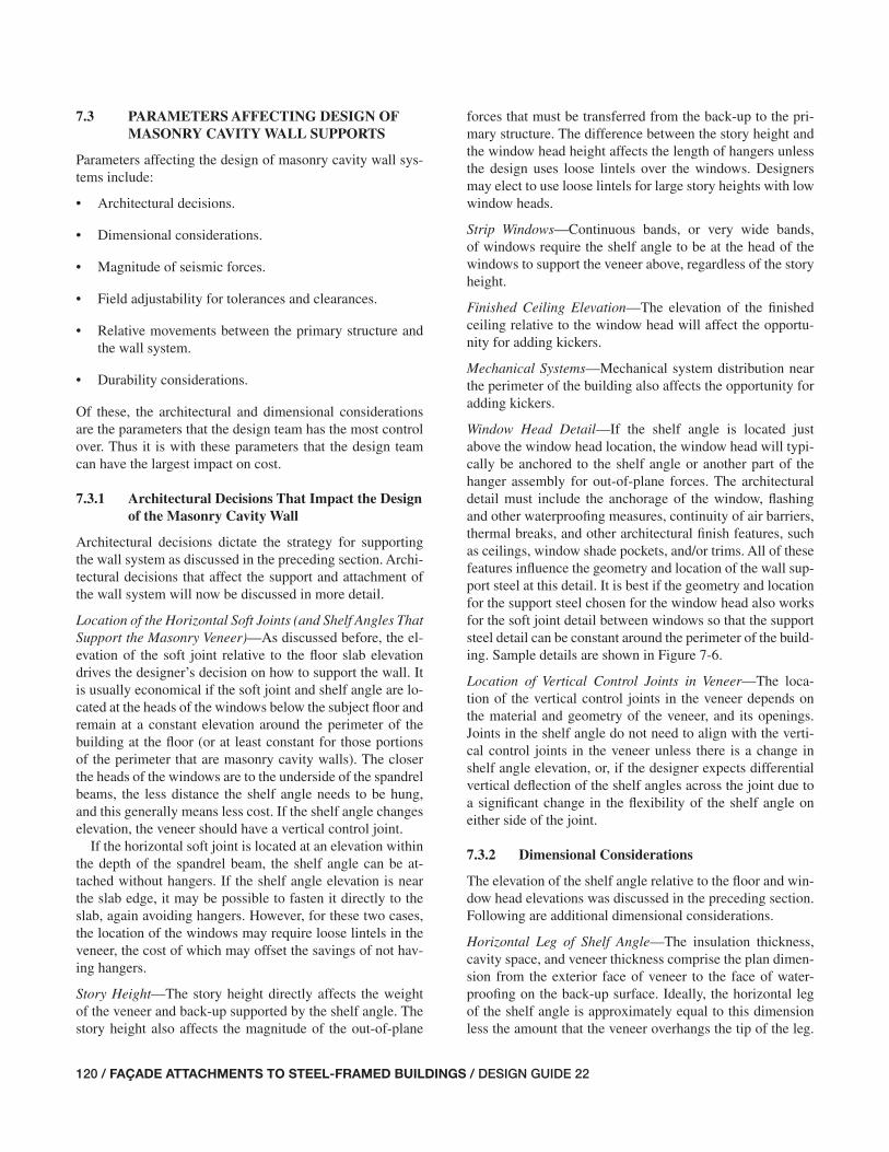
120 / FAÇADE ATTACHMENTS TO STEEL-FRAMED BUILDINGS / DESIGN GUIDE 22
7.3 PARAMETERS AFFECTING DESIGN OF MASONRY CAVITY WALL SUPPORTS
Parameters affecting the design of masonry cavity wall sys-tems include:
• Architectural decisions.
• Dimensional considerations.
• Magnitude of seismic forces.
• Field adjustability for tolerances and clearances.
• Relative movements between the primary structure and the wall system.
• Durability considerations.
Of these, the architectural and dimensional considerations are the parameters that the design team has the most control over. Thus it is with these parameters that the design team can have the largest impact on cost.
7.3.1 Architectural Decisions That Impact the Design of the Masonry Cavity Wall
Architectural decisions dictate the strategy for supporting the wall system as discussed in the preceding section. Archi-tectural decisions that affect the support and attachment of the wall system will now be discussed in more detail.
Location of the Horizontal Soft Joints (and Shelf Angles That Support the Masonry Veneer)—As discussed before, the el-evation of the soft joint relative to the fl oor slab elevation drives the designer’s decision on how to support the wall. It is usually economical if the soft joint and shelf angle are lo-cated at the heads of the windows below the subject fl oor and remain at a constant elevation around the perimeter of the building at the fl oor (or at least constant for those portions of the perimeter that are masonry cavity walls). The closer the heads of the windows are to the underside of the spandrel beams, the less distance the shelf angle needs to be hung, and this generally means less cost. If the shelf angle changes elevation, the veneer should have a vertical control joint.
If the horizontal soft joint is located at an elevation within the depth of the spandrel beam, the shelf angle can be at-tached without hangers. If the shelf angle elevation is near the slab edge, it may be possible to fasten it directly to the slab, again avoiding hangers. However, for these two cases, the location of the windows may require loose lintels in the veneer, the cost of which may offset the savings of not hav-ing hangers.
Story Height—The story height directly affects the weight of the veneer and back-up supported by the shelf angle. The story height also affects the magnitude of the out-of-plane
forces that must be transferred from the back-up to the pri-mary structure. The difference between the story height and the window head height affects the length of hangers unless the design uses loose lintels over the windows. Designers may elect to use loose lintels for large story heights with low window heads.
Strip Windows—Continuous bands, or very wide bands, of windows require the shelf angle to be at the head of the windows to support the veneer above, regardless of the story height.
Finished Ceiling Elevation—The elevation of the fi nished ceiling relative to the window head will affect the opportu-nity for adding kickers.
Mechanical Systems—Mechanical system distribution near the perimeter of the building also affects the opportunity for adding kickers.
Window Head Detail—If the shelf angle is located just above the window head location, the window head will typi-cally be anchored to the shelf angle or another part of the hanger assembly for out-of-plane forces. The architectural detail must include the anchorage of the window, fl ashing and other waterproofi ng measures, continuity of air barriers, thermal breaks, and other architectural fi nish features, such as ceilings, window shade pockets, and/or trims. All of these features infl uence the geometry and location of the wall sup-port steel at this detail. It is best if the geometry and location for the support steel chosen for the window head also works for the soft joint detail between windows so that the support steel detail can be constant around the perimeter of the build-ing. Sample details are shown in Figure 7-6.
Location of Vertical Control Joints in Veneer—The loca-tion of the vertical control joints in the veneer depends on the material and geometry of the veneer, and its openings. Joints in the shelf angle do not need to align with the verti-cal control joints in the veneer unless there is a change in shelf angle elevation, or, if the designer expects differential vertical defl ection of the shelf angles across the joint due to a signifi cant change in the fl exibility of the shelf angle on either side of the joint.
7.3.2 Dimensional Considerations
The elevation of the shelf angle relative to the fl oor and win-dow head elevations was discussed in the preceding section. Following are additional dimensional considerations.
Horizontal Leg of Shelf Angle—The insulation thickness, cavity space, and veneer thickness comprise the plan dimen-sion from the exterior face of veneer to the face of water-proofi ng on the back-up surface. Ideally, the horizontal leg of the shelf angle is approximately equal to this dimension less the amount that the veneer overhangs the tip of the leg.
115-156_DG22_Ch07.indd 120 7/16/08 4:46:57 PM

DESIGN GUIDE 22 / FAÇADE ATTACHMENTS TO STEEL-FRAMED BUILDINGS / 121
Fig. 7-6. Shelf angle with structural spacer to extend shelf under veneer.
However, with modern energy codes increasing the thick-ness of insulation required in the cavity, it may become im-practical to have the shelf this wide. When the vertical leg of the shelf angle is outward from the face of the back-up, a structural spacer can be used between the back of the angle and the hanger so that the outside face of the hanger can be behind the waterproofi ng membrane. See Figure 7-6. At a minimum, two-thirds of the width of the masonry veneer should bear on the shelf angle.
It is best practice to coordinate the dimension of the hori-zontal leg of the shelf angle so that a rolled angle shape fi ts. Trimming the leg of a standard-shaped angle is not economi-cal. Using a bent plate is generally not practical because the tolerances of the bending are not adequate, the bend radius for the required thickness is relatively large, and the fabrica-tion is more costly.
Thickness of the Back-up Wall—The thickness of the back-up wall may affect the designer’s decisions about the location of the slab edge, the centerline of the spandrel beam, and the centerline of the exterior columns. Considerations include whether the back-up runs past the edge of the slab or past the spandrel beam to the underside of the slab, and whether the back-up runs outside the columns or the columns interrupt the back-up.
Relative Geometry of Slab Edge, Spandrel Centerline, and Column Centerline—This geometry must come together to balance competing requirements. For example, increasing
the slab edge overhang from the spandrel and column cen-terlines may facilitate the back-up wall cleanly running past the column. However, this may also increase the eccentricity of the load. Holding the spandrel centerline back from the slab edge increases space for clearances and adjustability of the shelf angle assembly but, again, increases eccentricity.
7.3.3 Field Adjustability
Given the fabrication and erection tolerances of the steel frame, the support details for the masonry cavity walls require fi eld adjustments. The magnitude of the necessary adjust-ments depends on the number of stories and the span lengths as discussed in Chapter 4. It is not uncommon for project conditions to necessitate the ability to adjust the location of the tip of the shelf angle to within ±8 in. of theoretical verti-cal and horizontal. Suggested adjustments include:
• Means to adjust the slab edge in or out relative to the spandrel beam.
• Means to adjust the location of the back-up wall in or out relative to the slab edge.
• Means to adjust the location of the shelf angle both verti-cally and horizontally.
Most projects have the fi nal shelf angle location set by the steel erector as a follow-up operation after erecting and plumbing the frame. The use of erection bolts in slotted
115-156_DG22_Ch07.indd 121 7/16/08 4:46:57 PM

122 / FAÇADE ATTACHMENTS TO STEEL-FRAMED BUILDINGS / DESIGN GUIDE 22
holes with fi eld welding is the most common mechanism for achieving the necessary fi eld adjustments.
7.3.4 Movement Requirements
Both vertical and in-plane movements will be discussed.
Vertical Movements—The design of the wall support and attachments must account for the vertical defl ections of the supporting steel and accommodate the vertical movements of the veneer due to volume change.
• Stiffness of spandrel beam and supporting structure: The designer must provide enough stiffness to mitigate crack-ing of the veneer due to support defl ection. Limiting the spandrel beam and associated support defl ections to less than the span divided by 600 is usually suffi cient for most stone and brick veneers. ACI 530-05/ASCE 5-05/TMS 402-05 limits defl ections from dead and live loads to the span divided by 600 or 0.3 in. However, this crite-rion usually does not control the design for typical spans of modern steel structures with spans of 25 to 40 ft. In-stead, the spandrel stiffness will usually be limited by the acceptable horizontal soft joint size. Note that there is a tradeoff between width of joints and required stiffness of spandrel beams.
• Design movement of horizontal soft joints: Horizontal soft joints must accommodate the vertical movement due to the relative defl ections of upper and lower fl oor struc-tures, plus the movement due to thermal and moisture volume changes in the veneer. The sum of the movement accommodated by the soft joint will be approximately 25 to 50 percent of the soft-joint size, depending on sealant materials and sealant bond, to account for sealant com-pressibility and extensibility. Thus, the stiffness of the spandrel and shelf angle supports is often controlled by the acceptable soft-joint size. This is especially true for brick veneers as the soft joints must accommodate the long term expansion of the brick due to absorption of moisture. Example 7.1 illustrates the design concepts of selecting the horizontal soft-joint size.
In-Plane Drift of the Steel Frame—The support and attach-ment details must allow the primary structure to undergo its design drift without restraint from the non-structural cavity wall. As the structure undergoes drift, the upper fl oor is mov-ing laterally relative to the lower fl oor. The common strategy of accommodating this movement is to anchor each story of wall to the lower fl oor where its weight is supported, and provide only out-of-plane lateral restraint at the top of the wall by connection to the upper fl oor. The connection at the top of the wall allows vertical movement and movement in the plane of the wall. The story of wall should not be con-nected to the frame at other locations, such as the columns,
unless such attachment allows suffi cient relative movement. The wall rotates about its base for lateral drift perpendicular to its plane, and moves as a relatively rigid body with the lower fl oor for in-plane lateral drift.
7.3.5 Durability
The current standard practice for design of masonry cavity walls assumes the cavity will be wet and incorporates a con-tinuous waterproofi ng membrane on the exterior face of the back-up (Brock, 2005). Designers must balance the reliabil-ity and life expectancy of the membrane with the durability of the façade support structure behind it. The shelf angle and support structure should be located on the dry side of a reli-able membrane and fl ashing system.
Structure on the dry side of the membrane is generally not galvanized or given protection greater than the primary building structure, which is often not protected. A usual ex-ception is the shelf angle itself, which is protected because it is at the base of the cavity where the most water is expected to accumulate. The fl ashing that protects the horizontal leg has splices that may be susceptible to leakage. Water that leaks past the fl ashing will tend to sit on the horizontal leg and not drain away. For these reasons, the shelf angle is often galvanized.
7.4 DESIGN RESPONSIBILITIES FOR MASONRY CAVITY WALLS
As discussed in Chapter 3, it is important that the design team understands the design responsibilities for the support of masonry cavity walls. Contracts can defi ne the design re-sponsibilities for each project, and one approach commonly found on projects with masonry cavity walls is discussed in the following text.
Architect—The architect normally has responsibility for the following:
• The performance of the cavity wall with respect to mois-ture and thermal protection of the building, and to the performance of the veneer, including anchorage to the back-up system.
• The selection of cavity wall dimensions, including face of back-up to exterior face of veneer, thickness of veneer, veneer overhang, and length of horizontal leg of shelf angle.
• The location of horizontal soft joints (and thus the loca-tion of the shelf angles).
• The dimension of the horizontal soft joint and perfor-mance of sealant joint (usually in consultation with the SER to understand practical limits for controlling move-ment due to the steel frame and shelf angle assembly).
115-156_DG22_Ch07.indd 122 7/16/08 4:46:58 PM

DESIGN GUIDE 22 / FAÇADE ATTACHMENTS TO STEEL-FRAMED BUILDINGS / 123
• The selection of the back-up wall material (block versus metal studs), and other attributes, such as maximum stud spacing and minimum gage based on fastening of exte-rior sheathing, interior fi nishes, and veneer anchors.
• The selection of the back-up wall thickness and struc-tural performance requirements (usually in consultation with the SER).
• The back-up wall plan location with respect to column and spandrel center lines.
• The selection of the strategy for supporting the back-up and veneer (usually in consultation with the SER).
• The setting of acceptable tolerances for erected and ad-justed location of the shelf angle.
Structural Engineer of Record (SER) —The SER normally has responsibility for the following:
• The design of the primary building structure, including the slab, slab edge detail, spandrel beam, roll beams, kickers, etc., to support the forces imposed by the ma-sonry cavity wall system with due consideration of stiff-ness requirements.
• The design of the shelf angle and its attachment to the structure, including hangers, kickers, and other structural steel elements to support the veneer and back-up.
• The design of the connections of these elements, with details that address each type of project condition.
• Providing for fi eld adjustment of the shelf angle and slab edge as necessary to address fabrication and erection tolerances.
• Providing the architect with structural design deformations at the shelf angle for use in designing the soft joints.
• Providing the architect with the vertical and in-plane movements that the top of the back-up wall connections must accommodate for structural deformations for inclu-sion in the back-up wall specifi cations and/or design.
• Indicating on the structural drawings pertinent assump-tions and limitations about the loads from the masonry cavity walls.
• Indicating load support points on the contract drawings.
• The review and approval of shop drawings and fi eld erection drawings for the effect of the back-up wall and attachments on the primary building structure.
Although the SER may not be under contract to design the back-up wall, the SER must understand the strategy for an-choring the back-up wall and design the primary building structure to accommodate this strategy. The SER should indicate pertinent assumptions and any limitations.
Back-up Wall Designer—For metal stud back-up walls, project documents often specify that the contractor hire a specialty structural engineer (SSE) to design the back-up. The SSE designs and specifi es the back-up wall and its an-chors to the primary building structure to meet performance requirements provided in the project specifi cations.
For block back-up, the practice of using an SSE for design of the block and its anchorage is less consistent. For many projects the design team will provide the back-up design in-cluding reinforcement, slab dowels, and top of wall anchor-age. Whether it is shown on the structural drawings or archi-tectural drawings depends on the contractual agreement of the design team. Top-of-wall anchorage details often call for steel plates, bent plates, or angles. If they are shown on the structural drawings and are structural steel items as defi ned in AISC Code of Standard Practice, Section 2.1, they are usu-ally procured with the steel package. They may be installed by either the steel erector or the mason, depending on project conditions and choice of the construction manager. The ac-tual intention of the design team for procurement and instal-lation should be well defi ned in the contract documents.
7.5 DESIGN OF SHELF ANGLES
Grimm and Yura (1989) and Tide and Krogstad (1993) provide methods to design shelf angles. While both papers account for arching of masonry and fl exural and torsional deformations of the shelf angle, Grimm and Yura simplifi ed many of the calculations to ease hand calculations. However their method also contains limitations, the most notable of which are that the outstanding leg of the angle must be the long leg, and the spacing of shelf angle supports must not exceed 36 in. Tide and Krogstad provides a method that is computationally more involved, but does not have the same restrictions. Tables 7-1 through 7-5 (see end of Chapter 7) provide shelf angle mid-span tip defl ections for various angle shapes, loads, and spans based on the method provided by Tide and Krogstad (1993).
7.6 HUNG SHELF ANGLE—BACK-UP SUPPORTED BY SLAB
An illustration of a hung shelf angle detail is shown in Fig-ure 7-7. In this fi gure the shelf angle hangs a modest distance below the bottom fl ange of the spandrel beam. Kickers to the bottom fl ange of the spandrel, or alternatively roll beams, resist twisting of the spandrel, allowing the fi nished ceiling to be above the shelf angle elevation. Important attributes of this detail include:
115-156_DG22_Ch07.indd 123 7/16/08 4:46:58 PM

124 / FAÇADE ATTACHMENTS TO STEEL-FRAMED BUILDINGS / DESIGN GUIDE 22
Fig. 7-7. Hung shelf angle with back-up wall supported on slab.
115-156_DG22_Ch07.indd 124 7/16/08 4:46:58 PM

DESIGN GUIDE 22 / FAÇADE ATTACHMENTS TO STEEL-FRAMED BUILDINGS / 125
• Field application of a light-gage metal pour stop pro-vides adjustment of the slab edge location. The slab is designed to cantilever over the spandrel and pick up the weight of the back-up. If the back-up load is too large for the slab, a steel bent plate or angle can be used. It is designed as a cantilever from the spandrel fl ange, or supported by the hanger stiffeners and designed to span between them.
• Full-depth stiffener plates provide brackets that project from the spandrel beam to pick up the hanger. Typical spacing of the bracket plates ranges from 3 to 5 ft, de-pending on project conditions.
• The hangers are single steel angles, though double an-gles, WT sections, channels, and HSS are other common hanger shapes. Erection bolts in long horizontal slots in the hanger and long vertical slots in the bracket plates allow for fi eld adjustment prior to welding. A single hanger on one side of the bracket is preferred as this allows fi eld welding on both the near and far sides of the hanger. Designers can use slip-critical bolts for fi nal connections, but plate washers will be required on both sides due to the slotted holes.
• The hangers are designed for fl exure as well as tension. The fl exure comes from both the eccentric veneer load and the horizontal forces from the veneer and the back-up. In particular, the horizontal out-of-plane force from the top of the back-up wall of the story below is applied at the bottom of the hanger. Alternatively, kickers can be used to resist this force.
• Clearance is required between the inside edge of the hanger and the outside tips of the spandrel fl anges, and should account for the fi eld adjustment.
• The shelf angle can be shop welded or bolted to the hanger because the adjustability is provided between the hanger and the bracket plate. Designers can choose to provide additional fi eld adjustment with erection bolts and slotted holes. It is usually not suffi cient to try to provide the only adjustment at the shelf angle to hanger connection because the “in-and-out” adjustment has to be made with shimming, and this can be cumbersome and problematic.
• Planning for a nominal overhang of the back-up but designing it to be either zero or twice as large as theo-retically required allows for fi eld adjustment of the face of the back-up relative to the slab edge. For example, planning on 1 in. but designing for 2 in. of overhang will provide for a 1 in. adjustment in or out. This adjustment of the back-up location can lessen the amount of slab edge adjustment needed.
• The back-up wall is anchored to the top of the slab. If the back-up is a block wall, the primary building structure usually includes dowels from the slab. If the back-up is metal stud framing, the anchors to the slab are usually post-installed concrete anchors and not part of the pri-mary building structure.
• A short height of back-up wall is supported from the hanger assembly and spans to the underside of the slab or deck. Clearance should be provided between the outside tips of the spandrel fl anges and the backside of the back-up for tolerance and fi reproofi ng.
• A continuous plate, angle, or other element shop attached to the hangers can be used to provide a means to support the short height of back-up, and a place to anchor the top of the back-up wall below the window head.
• The connection of the back-up wall to the underside of the hangers must resist out-of-plane forces from the wall but allow suffi cient relative movement between the wall and the hanger assembly. The relative movements include both the vertical movement due to differential defl ection of the fl oors and the in-plane movement due to story drift of the frame.
An example structural detail of a hung shelf angle is pro-vided in Figure 7-8.
The locations of the hangers should be planned by the design team. Such a typical detail provides the maximum spacing of the hangers covering most conditions for most projects. However, the detailer should still be given direction by the designers on special conditions, such as near the ends of the spandrels at columns, at exterior corners, and at jogs or other articulations in the perimeter building line. Figure 7-9 provides examples of such conditions.
An example of a hung shelf angle detail with the shelf angle hung a large distance below the spandrel is shown in Figure 7-10. In the example, project conditions allow kickers to extend below the spandrel beam and close to the bottom of the hangers. Important attributes of this detail are:
• For adjustment of the hanger assembly, adjustment must be provided in the connection of the kicker to the hanger as well as in the connection of the hanger to the spandrel.
• Longer hangers will allow additional rotation of the shelf angle if their size is not increased relative to shorter hangers. If the kicker-to-hanger connection is designed as a pin, only the fl exural stiffness of the hanger resists rotation. If the connection is designed as rigid, the de-signer can account for the fl exural stiffness of the kicker as well, as illustrated in Figure 7-11.
115-156_DG22_Ch07.indd 125 7/16/08 4:46:59 PM

126 / FAÇADE ATTACHMENTS TO STEEL-FRAMED BUILDINGS / DESIGN GUIDE 22
• The twist of the spandrel beam due to the eccentricity of the hangers should be considered. To be concentric with the spandrel, the hanger can be pulled in or the spandrel can be pushed out. If the hanger is moved in, a bracket with adjustability at the shelf angle is needed. This will increase the rotation that the hanger and kicker need to resist. If the spandrel is moved outward, it will interrupt the back-up wall. The designer must understand how the sheathing, waterproofi ng, and veneer anchors will be lat-erally supported over the depth of the spandrel, as well as the impact this may have on the fi reproofi ng of the spandrel.
• The horizontal force on the kicker may be large because the tributary area may be large. The interior beam and slab must resist the uplift and the horizontal component must be transferred into the slab and deck.
For long hangers, it may be more economical to provide fewer, heavier hangers using HSS to span between them and support the shelf angle. Perhaps the hangers can be locat-ed at the quarter- or third-points of the spandrel beam. The HSS/shelf angle assembly is supported by the hangers, and by brackets from the columns. Figure 7-12 illustrates this concept.
An alternative to using kickers for a hung shelf angle de-tail with long hangers is shown in Figure 7-13. This example eliminates the kickers and adds a horizontal girt at the base of the hanger. Important attributes of this detail are:
• The gravity loads are taken to the spandrel by the hang-ers. The girt spans between columns to resist out-of-plane wall forces from the wall above and below the girt.
• The girt also resists a horizontal force that results from the vertical loads being eccentric from the hanger. The fl exural stiffness of the hanger resists the rotation of the shelf angle. Designers should also consider the lateral displacement of the girt. Limiting the lateral defl ection of the girt to L/600 to L/720 is suffi cient for most ma-sonry veneers.
• There is still twist of the spandrel beam due to the hanger being eccentric.
• The fi nished ceiling can be high relative to the shelf an-gle since there are no kickers. However, the architectural fi nish must account for the girt either by making a soffi t around it or thickening the wall.
Example 7.3 illustrates the design concepts for a hung shelf angle detail.
Fig. 7-8. Example structural detail—hung shelf angle.
115-156_DG22_Ch07.indd 126 7/16/08 4:46:59 PM
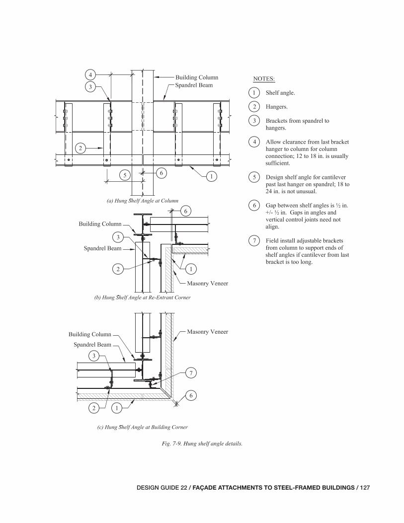
DESIGN GUIDE 22 / FAÇADE ATTACHMENTS TO STEEL-FRAMED BUILDINGS / 127
Fig. 7-9. Hung shelf angle details.
115-156_DG22_Ch07.indd 127 7/16/08 4:46:59 PM
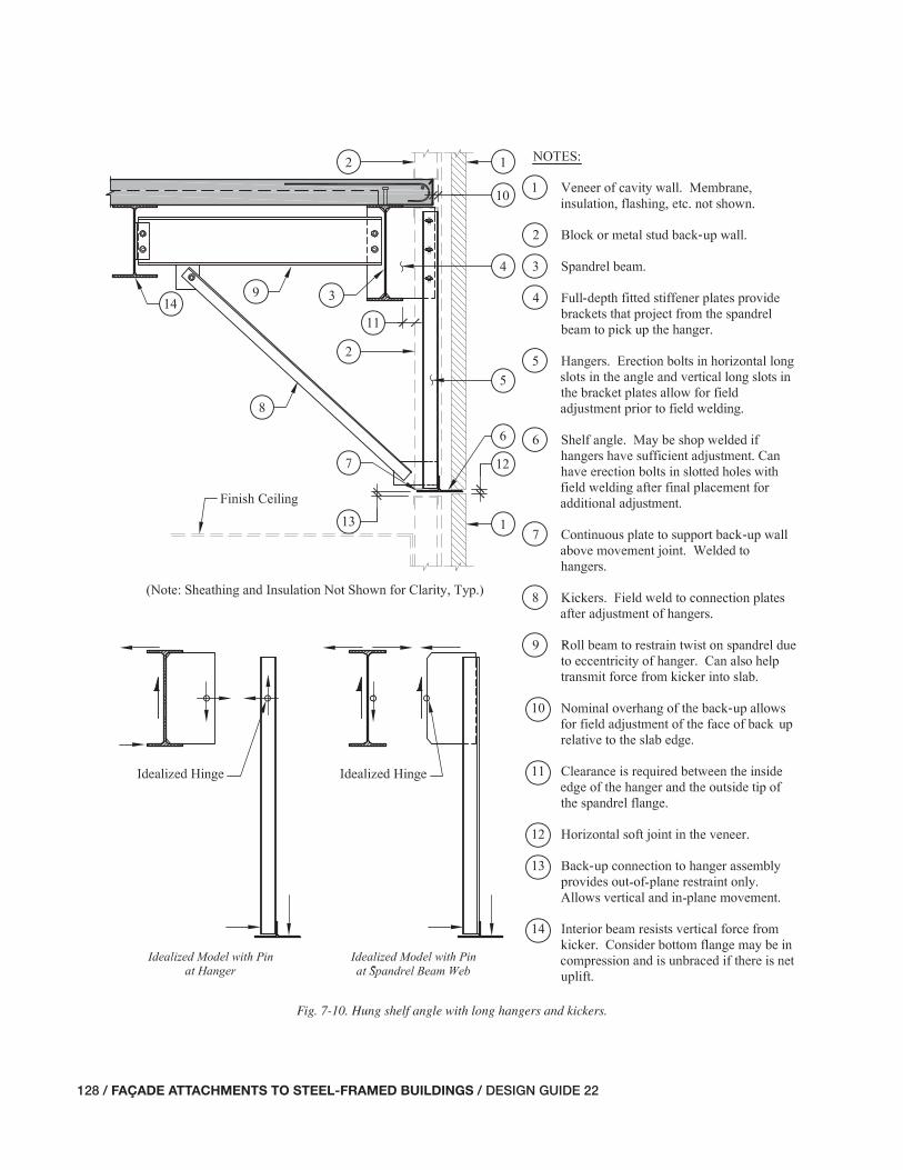
128 / FAÇADE ATTACHMENTS TO STEEL-FRAMED BUILDINGS / DESIGN GUIDE 22
Fig. 7-10. Hung shelf angle with long hangers and kickers.
115-156_DG22_Ch07.indd 128 7/16/08 4:47:00 PM

DESIGN GUIDE 22 / FAÇADE ATTACHMENTS TO STEEL-FRAMED BUILDINGS / 129
Fig. 7-11. Rotation in hung shelf angle due to fl exure in hangers and kickers.
Fig. 7-12. Alternative strategy for hung shelf angle with long hanger and kickers.
115-156_DG22_Ch07.indd 129 7/16/08 4:47:01 PM

130 / FAÇADE ATTACHMENTS TO STEEL-FRAMED BUILDINGS / DESIGN GUIDE 22
Fig. 7-13. Hung shelf angle with long hangers without kickers.
7.7 HUNG SHELF ANGLE—BACK-UP RUNS BY SLAB EDGE
For cavity walls made with block back-up, the back-up is usually supported on the slab as discussed in the previous section. When the back-up wall is made of metal studs, de-signers have the option of running the studs past the edge of the slab. This is ideal for parapets and strip windows because the studs can cantilever by the edge of the slab up to the window or parapet.
Figure 7-14 shows an example detail of a hung shelf angle with the metal stud back-up running by the edge of the slab. Important attributes of this detail are:
• The shelf angle is hung from steel bracket plates extend-ing from the spandrel beam with single-angle hangers. The hanger assembly and its connections are similar to those discussed in Section 7.5. The benefi t of support-ing the shelf angle with structural steel (as opposed to fastening it directly to the metal studs) is that the shelf angle is then erected and adjusted by the steel erector.
• The back-up wall weight is supported on the hanger as-sembly. Therefore, the connection to the slab edge need only be for the out-of-plane forces.
115-156_DG22_Ch07.indd 130 7/16/08 4:47:01 PM

DESIGN GUIDE 22 / FAÇADE ATTACHMENTS TO STEEL-FRAMED BUILDINGS / 131
Fig. 7-14. Hung shelf angle with metal studs running past slab edge.
115-156_DG22_Ch07.indd 131 7/16/08 4:47:02 PM

132 / FAÇADE ATTACHMENTS TO STEEL-FRAMED BUILDINGS / DESIGN GUIDE 22
• The metal studs can be connected to the slab edge by anchoring to the top of slab (shown) or to the front edge of the slab.
If the metal studs are connected to the top of the slab, the designer may choose to form the edge of the slab with a light-gage metal pour stop. A continuous cold-formed metal angle is attached to the back of the studs and anchorage to the top of the slab is provided with post-installed anchors. Alternatively, steel embed plates can be provided in the slab, though this will likely require a steel angle or bent plate to form the slab edge so as to have a means to hold the embeds in place during concrete operations.
If the metal studs are connected to the front edge of the slab, a steel angle or bent plate must be designed. A connec-tion clip should be provided for each individual stud. The clips are usually fi eld welded to the steel edge as it is dif-fi cult to drill and place concrete anchors through the steel edge member.
A gap should be provided between the back of the stud and the slab edge. This allows for fi eld adjustment of the location of the back-up wall relative to the slab edge. The amount of adjustment necessary depends on the degree to which the fi eld adjustment of the slab edge addresses the steel frame tolerances.
The shelf angle can be supported directly from the metal studs. This has the advantage of eliminating the steel bracket plates and hanger assemblies. It also facilitates erecting the back-up wall in pre-assembled panels with the shelf angle shop applied to the studs. However, a disadvantage is that all the fi eld adjustment must now occur in the connection of the panel to the slab. The metal stud-to-slab edge con-nection must also carry the weight of the back-up panel and subsequent veneer. It is also diffi cult to weld unless the cold-formed studs are made of fairly heavy gage material, such as 16 gage or heavier.
7.8 SHELF ANGLE SUPPORTED AT SLAB EDGE
Examples of shelf angles supported at a slab edge are shown in Figure 7-15. Supporting the shelf angle at the slab edge is usually best when the project already has a robust slab for other reasons. The elevation of the horizontal leg of the angle relative to the slab elevation is crucial. An inch or two up or down relative to the slab is the difference between a clean and sometimes awkward connection detail.
Important attributes of details for supporting the shelf angle at the slab edge are:
• The slab should be designed with adequate shear and fl exural strength to overhang the spandrel and support the wall. Otherwise, a very heavy bent plate or angle is required and it may still need to be stiffened. With the slab properly designed to support the wall, the spandrel
does not have the tendency to twist. If the slab is not ad-equate and a plate or bracket cantilevers from the span-drel, kickers or rolls beams may be necessary to resist the torsion in the spandrel.
• A steel angle or bent plate should be provided as a pour stop and a means to connect the shelf angle to the slab. Ample in-and-out fi eld adjustment should be provided for this bent plate.
• Headed studs or deformed bar anchors with threaded couplers welded to the vertical leg of the bent plate should be used to transfer the veneer load to the slab.
• The shelf angle should be fi eld welded to the bent plate pour stop. Erection bolts and long slotted holes can be used in the vertical leg of the shelf angle for vertical ad-justment in the fi eld. Adequate space must be provided for fi eld weld, accounting for the vertical adjustment of the shelf angle.
• Clearance should be provided between the back-up wall and the outside tips of the spandrel beam fl anges to al-low the back-up wall to be connected to the underside of the bent plate at the slab overhang. This connection must transfer out-of-plane forces from the wall to the slab but also allow both vertical movement between the slab and the lower back-up wall and in-plane movement of the wall relative to the slab for story drift of the frame.
Example 7.5 illustrates the design concepts for a shelf angle supported at the slab edge.
7.9 POTENTIAL PROBLEMS WITH SUPPORT AND ANCHORAGE OF MASONRY CAVITY WALLS
The following is a list of potential problems that designers should be aware of and avoid when designing the support and anchorage systems for masonry cavity walls. There is no particular meaning implied by the order of the list.
• Inadequate provisions for the shelf angle adjustment can cause the masonry to have too little bearing on the shelf angle.
• Inadequate provisions for the shelf angle adjustment can cause the masonry cavity to be too wide for the specifi ed masonry ties.
• Improper fl ashing design may not accommodate the pro-jection of bolts or fasteners into the cavity at the shelf angle.
• Inadequate soft-joint size may cause over compression of the sealant, causing it to bulge out.
115-156_DG22_Ch07.indd 132 7/16/08 4:47:03 PM

DESIGN GUIDE 22 / FAÇADE ATTACHMENTS TO STEEL-FRAMED BUILDINGS / 133
Fig. 7-15. Relieving angle supported on slab edge.
115-156_DG22_Ch07.indd 133 7/16/08 4:47:03 PM

134 / FAÇADE ATTACHMENTS TO STEEL-FRAMED BUILDINGS / DESIGN GUIDE 22
• Inadequate clearance between the bottom of the shelf angle and the top of the masonry veneer may result in bearing of the shelf angle on the masonry due to spandrel defl ections.
• Support details for the shelf angles at corners and atypi-cal conditions are not clearly documented in the design.
Example 7.1—Determination of Defl ections for Structures Supporting Brick Veneers
For the clay brick veneer on a building supported at each fl oor level by a shelf angle, determine the amount by which the brick will expand and the amount by which the spandrel beam can defl ect before compressing the joint fi ller material to its maximum allowable compressibility.
Given:The brick height between the shelf angles, h = 14 ft. The vertical as-built construction tolerance of the building, Tol = 8 in. The shelf angle defl ection under the weight of the brick with respect to the fl oor below, δa = z in.
The brick veneer is installed at an ambient temperature of 40 °F. The exterior wall of the building may experience a change in temperature, ΔT = 100 °F. The brick coeffi cient of thermal expansion, α = 4 × 10⁻⁶ in./in./°F, and the brick coef-fi cient of moisture expansion, ke = 3 × 10⁻⁴ in./in.
The largest design gap width before sealant installation, J′ = d in. The joint fi ller material is a high-performance sealant and the compressibility of the sealant material, M = 50%.
Solution:The volume change of the brick between the shelf angles is,
δvb = keh + αΔTh
= (3 × 10⁻⁴ in./in.)(14 ft)(12 in./ft)
+ (4 × 10⁻⁶ in./in./°F)(100 °F)(14 ft)(12 in./ft)
= 0.118 in.
The amount of movement that the joint can accommodate is,
δ jm M J Tol= ′ −( )= −( )=
0 50
0 375
.
.
d 8in. in.
iin.
Thus, the permissible structural defl ection, including the defl ection due to the loads applied prior to installation of the sealant joint is,
δ δ δs jm vb= −
= −=
0 375 0 118
0 257
. .
.
in. in.
in.
The permissible de� ection for the spandrel beam includes both vertical de� ections and torsional rotations as described in Chapter 5. Note that this de� ection, δs, is less than L/600 for beams spanning greater than 12 ft 10 in.
The total structural defl ection is δsil + Mδps, where
δ δ δps sb a= +′
The defl ection of the spandrel beam, δ′sb, due to the brick load and δa is the total defl ection of the shelf angle due to the brick load. Substituting this quantity back into the equation for the total structural defl ection, and limiting the total to not exceed δs,
δ δ δ δsil sb a sM M+ + ≤′
The defl ection of the spandrel beam is proportional to the load on it. Knowing that the uniformly distributed load due to the brick on the spandrel is wsb and the superimposed load is wsil, the defl ection of the spandrel beam due to the uni-formly distributed load due to the brick is,
δ δsb sil
sb
sil
w
w=′
This ratio assumes that the interior beams are parallel to the spandrel beam and do not frame into the spandrel beam. The assumption may still be a reasonable approximation when fl oor beams frame to the spandrel beam. Substituting this relationship back into the equation for δs above gives,
δ δ δ δsil sil
sb
sila sM
w
wM+
⎛
⎝⎜⎞
⎠⎟+ ≤
Rearranging this for δsil, the amount the spandrel beam can defl ect is,
δδ δ
sils a
sb
sil
M
Mw
w
≤−
+⎛
⎝⎜⎞
⎠⎟
≤−
1
0 257 in.. 00 50
1 0 50 1
0 151
.
.
.
z in.
in.
( )+ ( )
≤
Comments:
This example shows how to determine the permissible struc-tural defl ection when considering the size of soft (control) joints for brick veneers. Although the design of this joint generally is not in the scope of work for the SER, a gen-eral knowledge of proper joint design is often useful for the SER.
115-156_DG22_Ch07.indd 134 7/16/08 4:47:04 PM

DESIGN GUIDE 22 / FAÇADE ATTACHMENTS TO STEEL-FRAMED BUILDINGS / 135
The design gap before sealant installation may be expressed by the following equation:
′ =
+ ++ +J
h k h
MTol
T e silps
α δδ
Δ
where δps = the relative de� ection of the structure with respect
to the brick below the shelf angle that occurs after the shelf angle is set but before sealant installation
δsil = the de� ection due to superimposed loads applied to the spandrel beam supporting the shelf angle after the sealant has been installed in the joint
This expression can be rearranged to determine the total de-fl ection that can be tolerated:
( ) ( )δ δ αsil ps T eM M J Tol h k h+ = ′ − − +Δ
Note that the shelf angle defl ection includes defl ection of the horizontal leg of the angle as well as the defl ection of the re-lieving angle between attachments to the building structure.
For coef� cients of thermal and moisture expansion, refer to American Concrete Institute ACI 530-05, Building Code Requirements for Masonry Structures, for coef� cients for masonry. The Brick Industry Association also provides ex-cellent guidance (Brick Industry Association, 2000).
This calculation requires the designer to make assumptions about the brick and superimposed loads on the beam, which may be diffi cult during preliminary design. In practice, it is conservative and often easier to use the total of the brick defl ection and the superimposed load defl ection such that:
δ δ δs ps sil= +
Note that at the � rst elevated � oor level where the brick be-low the shelf angle is supported on a foundation wall, δps may be signi� cant. At upper � oor levels, however, where the spandrel beam on the � oor below the shelf angle may de� ect approximately as much as the spandrel beam supporting the shelf angle in question, δps may be small. Thus, one can often conservatively select a beam for which the total de� ection associated with cladding loads, superimposed dead loads, and live loads is less than δs.
Example 7.2—Selection of Shelf Angles to Support Brick Veneer Cladding
For the clay brick veneer on a building supported at each fl oor level by a shelf angle as illustrated in Figure 7-16, de-termine a shelf angle size that meets the defl ection criteria.
Given:
The brick height between the shelf angles, h = 14 ft. The shelf angle is supported by hangers at 3 ft on center along its length. The cavity width between the exterior face of the vertical leg of the shelf angle and the interior face of the brick, wc = 3 in. The width of the brick, wb = 3s in. The sheathing thickness, assuming the angle is thinner than the sheathing and the back of the vertical leg of the angle aligns with the back of the sheathing, tsh = s in.
For architectural reasons and to accommodate vertical de-fl ection of the supporting structure, the tip defl ection of the angle is limited to z in. Assume that lateral wind forces are resisted entirely by the back-up structure.
Solution:The required horizontal leg length of the shelf angle such that approximately two-thirds of the brick width sits on the shelf angle is,
lah = q wb + wc + tsh
= q(3s in.) + 3 in. + s in.
= 6.04 in.
Use an angle with a 6-in.-long horizontal leg.
Enter Table 7-3 (14-ft height of brick) with the 6-in. hori-zontal leg length, the z-in. maximum tip defl ection and 3-ft support spacing. An L6×4×a LLH has a maximum tip defl ection of 0.0625 in., which satisfi es the z-in. limit.
Use L6×4×aa LLH.
Comments:The design methodology used in this example is based upon Tide and Krogstad (1993), as are the tables in Chapter 7.
Fig. 7-16. Section of shelf angle supporting brick veneer.
115-156_DG22_Ch07.indd 135 7/16/08 4:47:04 PM
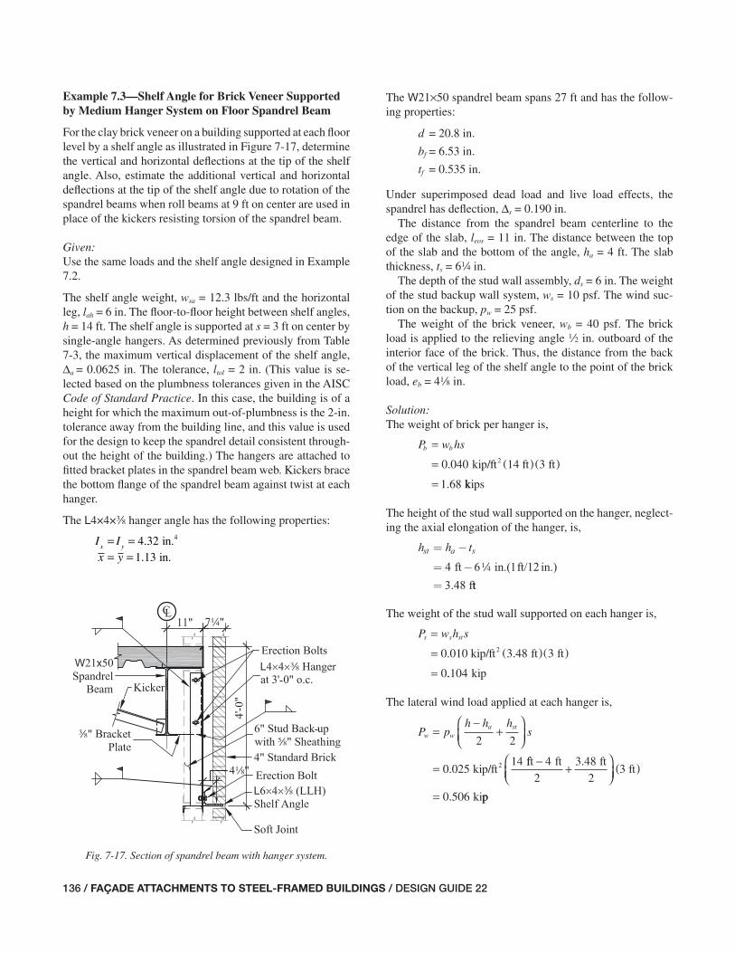
136 / FAÇADE ATTACHMENTS TO STEEL-FRAMED BUILDINGS / DESIGN GUIDE 22
Example 7.3—Shelf Angle for Brick Veneer Supported by Medium Hanger System on Floor Spandrel Beam
For the clay brick veneer on a building supported at each fl oor level by a shelf angle as illustrated in Figure 7-17, determine the vertical and horizontal defl ections at the tip of the shelf angle. Also, estimate the additional vertical and horizontal defl ections at the tip of the shelf angle due to rotation of the spandrel beams when roll beams at 9 ft on center are used in place of the kickers resisting torsion of the spandrel beam.
Given:Use the same loads and the shelf angle designed in Example 7.2.
The shelf angle weight, wsa = 12.3 lbs/ft and the horizontal leg, lah = 6 in. The fl oor-to-fl oor height between shelf angles, h = 14 ft. The shelf angle is supported at s = 3 ft on center by single-angle hangers. As determined previously from Table 7-3, the maximum vertical displacement of the shelf angle, Δa = 0.0625 in. The tolerance, ltol = 2 in. (This value is se-lected based on the plumbness tolerances given in the AISC Code of Standard Practice. In this case, the building is of a height for which the maximum out-of-plumbness is the 2-in. tolerance away from the building line, and this value is used for the design to keep the spandrel detail consistent through-out the height of the building.) The hangers are attached to fi tted bracket plates in the spandrel beam web. Kickers brace the bottom fl ange of the spandrel beam against twist at each hanger.
The L4×4×a hanger angle has the following properties:
I Ix yx y
= == =
4 321 13
4. .. .
inin
The W21×50 spandrel beam spans 27 ft and has the follow-ing properties:
d = 20.8 in.
bf = 6.53 in.
tf = 0.535 in.
Under superimposed dead load and live load effects, the spandrel has defl ection, Δs = 0.190 in.
The distance from the spandrel beam centerline to the edge of the slab, leos = 11 in. The distance between the top of the slab and the bottom of the angle, ha = 4 ft. The slab thickness, ts = 64 in.
The depth of the stud wall assembly, ds = 6 in. The weight of the stud backup wall system, ws = 10 psf. The wind suc-tion on the backup, pw = 25 psf.
The weight of the brick veneer, wb = 40 psf. The brick load is applied to the relieving angle 2 in. outboard of the interior face of the brick. Thus, the distance from the back of the vertical leg of the shelf angle to the point of the brick load, eb = 48 in.
Solution:The weight of brick per hanger is,
P w hsb b=
= (( ) )
=
0 040 3
1 68
.
.
kip/ft 14 ft ft2
kkips
The height of the stud wall supported on the hanger, neglect-ing the axial elongation of the hanger, is,
h h tst a s= −
= −
=
4 6 ft in.(1ft/12 in.)
3.48 f
4
tt
The weight of the stud wall supported on each hanger is,
P w h ss s st=
= ( () )
=
0 01 3 48 3
0
. .0 kip/ft ft ft2
..104 kip
The lateral wind load applied at each hanger is,
P ph h h
sw wa st=
−+
⎛⎝⎜
⎞⎠⎟
=
2 2
0 02514
kip/ft2.fft ft ft
ft
ki
− +⎛⎝⎜
⎞⎠⎟
)(
=
4
2
3 48
23
0 506
.
. pp
Fig. 7-17. Section of spandrel beam with hanger system.
115-156_DG22_Ch07.indd 136 7/16/08 4:47:04 PM

DESIGN GUIDE 22 / FAÇADE ATTACHMENTS TO STEEL-FRAMED BUILDINGS / 137
Both the brick and stud are eccentric to the centroid of the hanger as shown in Figure 7-18. Thus, the brick veneer and stud impose moments at the end of the hanger. However, the brick veneer and stud moments act in opposite directions.
The cantilever length of the hanger is,
L = h d t t
=
c a s f− +( ) +
( ) −4 ft 12 in./ft 20.8 inn. 6 in. 0.535 in.
= 21.5 in.
+( ) +4
Assuming that the hanger is fi xed for fl exure at the bottom of the bracket plate, the moment at the bottom of the hanger due to the eccentricity of the brick is,
M P e xb b b
= +( )= +( )1 68 4 1 13. .kips in. in.8
== 8 83. kip-in.
The moment at the bottom of hanger due to the eccentricity of the stud wall is,
M Pd
xs s
s= −⎛⎝⎜
⎞⎠⎟
= −⎛⎝
2
0 1046
21 13. .kip
in.in.⎜⎜
⎞⎠⎟
= kip-in.0 194.
The net moment at the bottom of hanger is,
M M Mnet b s
= −= −8 83 0 194. .kip-in. kip-in.
kip-in.= 8 64.
The rotation due to moment at the bottom of the hanger is,
θM
net c
x
M L
EI=
=( )8 64
29 000
.
,
kip-in. 21.5 in.
kssi 4.32 in.
rad.(or 0.0850
4( )= °0 00148. ))
The rotation due to the wind load at the bottom of the hanger is,
θw
w c
x
P L
EI=
=( )
2
2
2
0 506
2 29 000
.
,
kip 21.5 in.
ksii 4.32 in.
rad.(or 0
4( )( )= 0 000934 0534. . °°)
The horizontal distance between the centroid of the hanger and the tip of the angle leg is,
x x li ah
= += +=
1 13 6
7 13
.
.
in. in.
in.
The vertical displacement of the shelf angle due to rotation at the bottom of the hanger is,
Δv i w M
xθ θ θ= +( )= ( ) ° +
sin
. sin .in.7 13 0 0534 00 0850
0 0172
.
.
°( )= in.
The total vertical defl ection of the shelf angle is,
Δ Δ Δ Δ= + += + +
s a vθ
0 190 0 0625 0 0172. . . . . .in in in
0.270 in= .
Recall that Δs is the vertical defl ection of the spandrel beam due to live loads and superimposed dead loads. It accounts for the majority of the vertical defl ection of the shelf angle.
The lateral defl ection due to moment at the bottom of the hanger (see Figure 7-19) is,
Δhm
net c
y
M L
EI=
=( )
2
2
2
8 64
2 29
.
,
kip-in. 21.5 in.
0000 4 32
0 0159
ksi in.
in.
( )( )=
.
.
Fig. 7-18. Loads on hanger.
115-156_DG22_Ch07.indd 137 7/16/08 4:47:06 PM

138 / FAÇADE ATTACHMENTS TO STEEL-FRAMED BUILDINGS / DESIGN GUIDE 22
Fig. 7-21. Torsional loads on spandrel beam.
Fig. 7-22. Equivalent lateral forces on spandrel beam fl ange.
Fig. 7-19. Lateral defl ection of hanger due to moment.
Fig. 7-20. Lateral defl ection of hanger due to wind load.
The lateral defl ection due to the wind load at the bottom of the hanger (see Figure 7-20) is,
Δhww c
y
P L
EI=
=( )
3
3
3
0 506
3 29 000
.
,
kip 21.5 in.
kssi in.
in.
( )( )=
4 32
0 0134
.
.
The total horizontal defl ection at the bottom of the shelf angle is,
Δ Δ Δh hm hw= += +=
0 0159 0 0134
0 0293
. .
.
in. in.
in.
This defl ection is small and, therefore, neglected in the re-mainder of this example.
Consider roll beams at 9 ft on center in place of kickers. Without kickers to brace the bottom fl ange of the spandrel, torsion on the spandrel beam between the roll beams must be considered. Using the “fl exural analogy,” a relatively simple, conservative method is presented for calculating the additional vertical defl ection of the roll beams due to twist of the spandrel. The hangers are located at the third-points along the torsionally unbraced length. For simplicity, the
rotation of the roll beams will be neglected. See Figures 7-21 and 7-22.
The spandrel beam span for torsion is,
LT = 9 ft
The torsion imposed on the spandrel beam due to the brick at each hanger, neglecting the self-weight of the hangers, brackets, and shelf angles, is,
T P l l eb b eos tol b= + +( )= +kips in. in1 68 11 2. .. in.
kip-in.
+( )=
4
28 8
118
.
The torsion imposed on the spandrel beam due to the stud back-up wall at each hanger is,
= +T P l ld
s s eos tols+
⎛⎝⎜
⎞⎠⎟
=
2
0 104 11kip in.. ++ +⎡
⎣⎢
⎤
⎦⎥
=
26
2
1 66
in.in.
kip-in..
115-156_DG22_Ch07.indd 138 7/16/08 4:47:07 PM

DESIGN GUIDE 22 / FAÇADE ATTACHMENTS TO STEEL-FRAMED BUILDINGS / 139
The torsion imposed on the spandrel beam due to the wind load at each hanger is,
T P h tw w a s= −( )= ( ) −kip ft 12 in./ft0 506 4 6. 144 in.
kip-in.
⎡⎣ ⎤⎦= 21 1.
The torsion at each end of the span, assuming rotation about the spandrel top fl ange, is,
T T T Tb s w= + += + +kip-in. kip-in.28 8 1 66 21 1. . . kip-in.
kip-in.= 51 6.
The equivalent force to apply to the bottom fl ange is,
PT
dH =
=
=
51 6
2 48
.
.
kip-in.
20.8 in.kips
The moment of inertia of the spandrel beam bottom fl ange is,
It b
bf
f f=
=( )
=
3
3
12
0 535
1212 4
.
.
in. 6.53 in.
in.4
The lateral displacement of the spandrel beam bottom fl ange at the hanger location is,
ΔbfH T
bf
P L
EI=
=( )( )
5
162
5 2 48 9 12
3
3. kip ft in./fft
ksi in.4
( )( )( )
=
3
162 29 000 12 4
0 268
, .
. in.
This defl ection calculation assumes that the bottom fl ange of the spandrel consists of a single span that is simply supported at the roll beams. In reality, the bottom fl ange is continuous through this point, and the actual defl ection would be some-what less than determined here. If desirable, this continuity can be considered in the calculation.
The equivalent rotation at the top fl ange is,
θFA
bf
d=
⎛
⎝⎜
⎞
⎠⎟
=⎛
−
−
sin
sin.
.
1
1 0 268
20 8
Δ
in.
in.⎝⎝⎜⎞⎠⎟
= °0 738.
The initial horizontal and vertical distances between the cen-ter of the top fl ange of spandrel rotation and the bottom of the shelf angle is,
x l l li eos tol ah= + += + +=
11 2 6
19 0
in. in. in.
. in.
y h ti a s= −
= ( ) −
=
4 ft 12 in./ft 6 in.
in.
14
41 8.
The distance between the point of rotation and the tip of the shelf angle is,
r x yi i= +
= ( ) + ( )=
2 2
2 219 0 41 8
45 9
. .
.
in. in.
in.
The initial angle between the point of hanger rotation and the tip of the shelf angle with respect to vertical is,
α =⎛
⎝⎜⎞
⎠⎟
=⎛⎝⎜
⎞
−
−
tan
tan.
.
1
1 19 0
41 8
x
yi
i
in.
in.⎠⎠⎟
= °24 4.
The fi nal angle between the point of hanger rotation and the tip of the shelf angle due to lateral translation of the shelf angle is,
β α θ= −= ° − °= °
FA
24 4 0 738
23 7
. .
.
115-156_DG22_Ch07.indd 139 7/16/08 4:47:07 PM

140 / FAÇADE ATTACHMENTS TO STEEL-FRAMED BUILDINGS / DESIGN GUIDE 22
The fi nal position of the tip of the shelf angle with respect to the point of hanger rotation is,
x r
y
f = ( )= ( ) °( )=
sin
. sin .
.
β
45 9 23 7
18 4
in.
in.
f r= ( )= ( ) °( )=
cos
. cos .
.
β
45 9 23 7
42 0
in.
in.
The vertical and horizontal rigid body translation of the tip of the shelf angle due to rotation of the spandrel beam and lateral translation of the hanger is,
Δvrb f iy y= −
= −=
42 0 41 8
0 200
. .
.
in. in.
inn.
in. in.
Δhrb i fx x= −
= −=
19 0 18 4
0 60
. .
. 00 in.
The total vertical defl ection of the shelf angle (see Figure 7-23) is,
Δ Δ Δ Δ Δv s a v vrb= + + += + +
θ
in. in.0 190 0 0625. . 00 0172 0 200
0 470
. .
.
in. in.
in.
+=
The ratio of the vertical defl ection to beam span is,
L
vΔ=
( )
=
27
689
ft 12 in./ft
0.470 in.
The total horizontal defl ection of the shelf angle is,
Δ Δ Δ Δh hm hw hrb= + += + +in. in.0 0159 0 0134 0. . ..
.
600
0 629
in.
in.=
The ratio of the horizontal defl ection to the hanger length is,
h ta s
h
−=
( ) −Δ
4 ft 12 in./ft 6.25 in.
0.629 in.
= 66 4.
Comments:Additional cladding support design steps, such as the follow-ing, are not included in this example:
• Design of the angle hanger for combined fl exure and tension, considering yielding, lateral-torsional buckling, and leg local buckling for bending about the principal axes.
• Design of the fi eld welds between the shelf angle and the hanger.
• Design of the bracket plate, including the welds to the hanger and spandrel beam.
• Design of the kicker connection to the bottom fl ange.
This example shows that the designer may need to account for rotational defl ections due to the fl exural stiffness of a shelf angle hanger when calculating shelf angle defl ections. Tide and Krogstad (1993) assume the tip of the shelf angle defl ects and rotates downward, shifting the point of load of the relatively rigid brick away from the tip of the angle. They suggest that the brick load should be assumed to act on the angle at 2 in. outboard of the interior face of the brick.
For the case where kickers brace the bottom fl ange of the spandrel beam against twist at each hanger, the relative contributions of each defl ection component are summarized here.
Defl ection of shelf angle alone
ΔΔ
a = =0 062523 2
.. %
in.
0.270 in.Fig. 7-23. Lateral translation of shelf angle.
115-156_DG22_Ch07.indd 140 7/16/08 4:47:07 PM

DESIGN GUIDE 22 / FAÇADE ATTACHMENTS TO STEEL-FRAMED BUILDINGS / 141
Rotation of bottom of shelf angle
ΔΔ
vθ = =0 01726 4
.. %
in.
0.270 in.
Defl ection of spandrel beam alone
ΔΔ
s = =0 19070 4
.. %
in.
0.270 in.
Where roll beams brace the spandrel beam against twist at each hanger, the relative contributions of each defl ection component are summarized here.
Defl ection of shelf angle alone
ΔΔ
a
v
= =0 0625
0 47013 3
.
.. %
in.
in.
Rotation of bottom of shelf angle
ΔΔ
v
v
θ = =0 0172
0 4703 7
.
.. %
in.
in.
Defl ection of spandrel beam alone
ΔΔ
s
v
= =0 190
0 46940 4
.
.. %
in.
in.
Rigid-body rotation
ΔΔ
vrb
v
= =0 200
0 47042 6
.
.. %
in.
in.
Although the calculated vertical defl ection is less than L/600, it is still likely too large—assuming 50% compressibility of the sealant material, the horizontal sealant joint beneath the angle would have to be more than 1 in. wide to accommodate both the structural movement and the brick expansion.
The lateral translation of the shelf angle without kickers is also of concern.
Translation due to concentrated moment at bottom of hanger
Translation due to lateral wind force at bottom of hanger
Translation due to rigid body motion of spandrel
ΔΔ
hm
h
= =0.0159 in.
in.0 6292 5
.. %
ΔΔ
hw
h
= =0.0134 in.
in.0 6292 1
.. %
ΔΔ
hrb
h
= =0.600 in.
in.0 62995 4
.. %
While the fl oor slab may provide some torsional restraint to the beam (and reduce Δhrb), the calculated horizontal dis-placement is signifi cantly larger than L/600. If the bottom fl ange of the spandrel beam in this case is not laterally braced between the roll beams, a stiffer spandrel beam is required.
Example 7.4—Shelf Angle for Brick Veneer Supported by Long Hanger System on Floor Spandrel Beam
For the clay brick veneer supported at the fi rst elevated fl oor level of a building by a shelf angle as illustrated in Figure 7-24, determine the vertical and horizontal defl ections at the tip of the shelf angle assuming the kicker is:
(a) pin-connected to the hanger
(b) rigidly connected to the hanger
Given:The supported height of the brick, h = 18 ft. The slab thick-ness, ts = 64 in. The distance between the top of the slab and the bottom of the angle, ha = 8 ft. The distance between the top of the fi rst fl oor slab and the top of the foundation below, hs = 18 ft.
The wall is subjected to a “components and cladding” wind pressure, pw = 25 psf acting toward the building. The weight of the brick veneer, wb = 40 psf. The weight of the
Fig. 7-24. Section of spandrel beam with long hanger system.
115-156_DG22_Ch07.indd 141 7/16/08 4:47:08 PM

142 / FAÇADE ATTACHMENTS TO STEEL-FRAMED BUILDINGS / DESIGN GUIDE 22
Fig. 7-25. Loads on hanger.
stud backup wall system, ws = 10 psf. The depth of the stud wall assembly is ds = 6 in. Note that the weight of the shelf angle is neglected since its load causes the beam to defl ect before the brick is installed.
The shelf angle is an L6×4×2, the horizontal leg dimen-sion, lah = 6 in. The tolerance is ltol = 2 in. From Table 7-5, the maximum defl ection of the shelf angle is Δa = 0.0348 in.
Note that an angle with a minimum 4-in. leg perpendicu-lar to the façade is recommended to facilitate adjustability with respect to the façade. The L4×4×a hanger angle has the following properties:
A = 2.86 in.2
Ix = 4.32 in.4
x– = y– = 1.13 in.
s = 3 ft on center
The 2L3×3×4 kicker angle has the following properties:
A = 2.87 in.2
Ix = 2.46 in.4
αk = 45°
The W21×44 spandrel beam has the following properties:
d = 20.7 in.
tf = 0.450 in.
Under superimposed dead load and live load effects, the spandrel has defl ection, Δs = 0.216 in.
The distance from the spandrel centerline to the edge of the slab, leos = 11 in.
As in Example 7.3, assume that the brick load is applied to the relieving angle 2-in. outboard of the interior face of the brick. Thus, the distance from the back of the vertical leg of the shelf angle to the point of the brick load, eb = 48 in.
Solution (a): Kicker Pin-Connected to the Hanger
See Figure 7-25. The unbraced length of the hanger below the bracket is,
L h d t ta s f= − +( ) +
= ( ) −ft 12 in./ft in.8 20 7. + 6 in. in.
in.
14( ) +
=
0 450
69 5
.
.
The length of the kicker is,
Lh t
ka s
k
=−
( )
=( ) −
cos
cos
α
8 6
4
ft 12 in./ft in.14
55
127
°( )= in.
In this case, the kicker resists only axial loads.
The weight of brick per hanger is,
P w hsb b=
= ( )( )=
0 040 3
2 16
.
.
kip/ft 18 ft ft2
kkips
The height of the stud wall supported on the hanger is,
h h tst a s= −
= −⎛⎝⎜
⎞⎠⎟
=
86
12
7
ftin
in./ft
114
.448 ft
The weight of the stud wall supported on each hanger is,
P w h ss s st=
= ( )( )=
0 010 3. kip/ft 7.48 ft ft2
00 224. kip
The lateral wind load applied at the bottom of each hanger is,
P ph h h
sw ws a st=
−+
⎛⎝⎜
⎞⎠⎟
=
2 2
0 02518
kip/ft2.ft ft ft
ft
k
− +⎛⎝⎜
⎞⎠⎟
( )=
8
2
7 48
23
0 656
.
. iip
The hanger is fi xed for fl exure at the bottom of the bracket plate and pinned for fl exure where it attaches to the kicker. Also, the hanger rotates about its centroid. The moment
115-156_DG22_Ch07.indd 142 7/16/08 4:47:08 PM
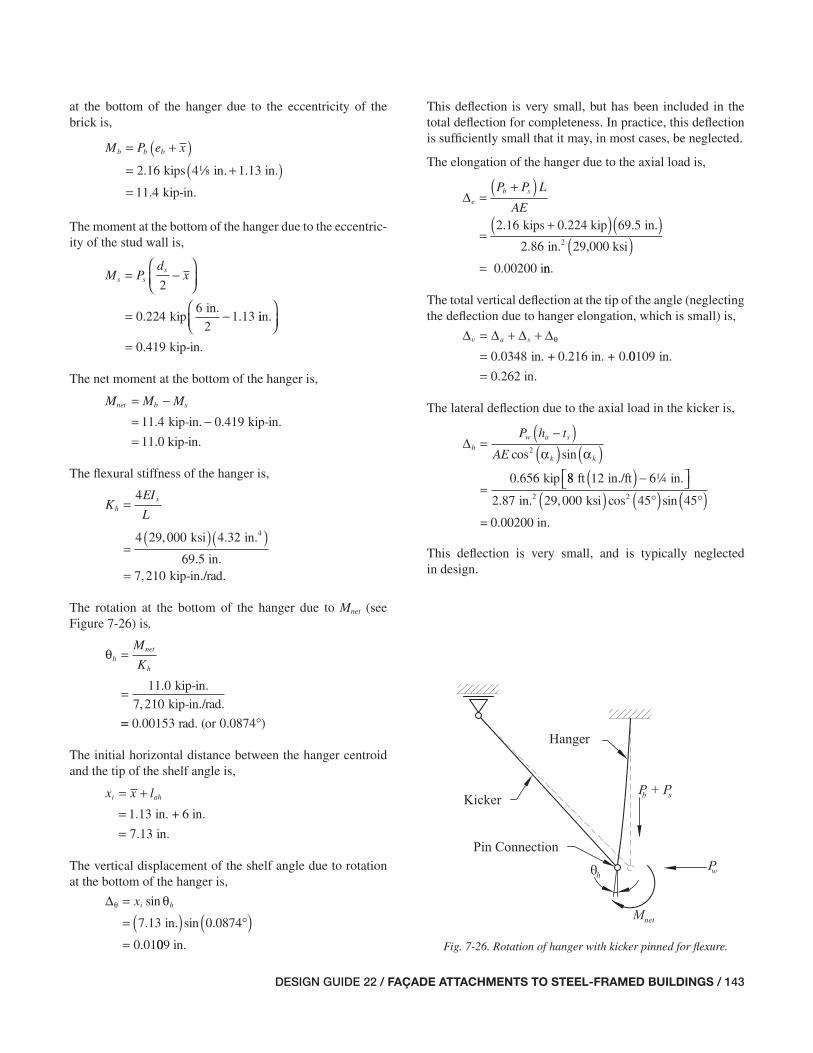
DESIGN GUIDE 22 / FAÇADE ATTACHMENTS TO STEEL-FRAMED BUILDINGS / 143
Fig. 7-26. Rotation of hanger with kicker pinned for fl exure.
at the bottom of the hanger due to the eccentricity of the brick is,
M P e xb b b= +( )= +(kips in. in.2 16 4 1 13. .18 )= kip-in.11 4.
The moment at the bottom of the hanger due to the eccentric-ity of the stud wall is,
= −M Pd
xs ss⎛
⎝⎜⎞⎠⎟
= −
2
0 2246
21 13kip
in.. . iin.
kip-in.
⎛⎝⎜
⎞⎠⎟
= 0 419.
The net moment at the bottom of the hanger is,
M M Mnet b s= −= −11 4 0 419. .kip-in. kip-in.
11.0 kip-in.=
The fl exural stiffness of the hanger is,
KEI
Lh
x=
=( )( )
4
4 29 000 4 32
69 5
, .
.
ksi in.
in.
4
kip-in./rad.= 7 210,
The rotation at the bottom of the hanger due to Mnet (see Figure 7-26) is,
θhnet
h
M
K=
= 11 0
7 210
.
,
kip-in.
kip-in./rad.
== °0 00153 0 0874. . )rad. (or
The initial horizontal distance between the hanger centroid and the tip of the shelf angle is,
x x li ah= +==
1 13
7 13
.
.
in. + 6 in.
in.
The vertical displacement of the shelf angle due to rotation at the bottom of the hanger is,
Δθ θ=
= ( ) °( )=
xi hsin
. sin .7 13 0 0874in.
0.01009 in.
This defl ection is very small, but has been included in the total defl ection for completeness. In practice, this defl ection is suffi ciently small that it may, in most cases, be neglected.
The elongation of the hanger due to the axial load is,
( )Δe
b sP P L
AE=
+
=+( )kips 0.224 kip2 16 69 5. . in.
in. 29,000 ksi
0.00200 i
2
( )( )
=
2 86.
nn.
The total vertical defl ection at the tip of the angle (neglecting the defl ection due to hanger elongation, which is small) is,
Δ Δ Δ Δv a s= + +=
θ
in. + 0.216 in. +0 0348 0. .00109 in.
0.262 in.=
The lateral defl ection due to the axial load in the kicker is,
( ) ( )( )
Δh
w a s
k k
P h t
AE=
−
=
cos sin
.
2
0 656
α α
kip 88 12 6
2 87 29 000
ft in./ft in.
in.2
( ) −⎡⎣ ⎤⎦14
. , ksi
= 0.00200 in.
( ) °( ) °( )cos sin2 45 45
This defl ection is very small, and is typically neglected in design.
115-156_DG22_Ch07.indd 143 7/16/08 4:47:09 PM
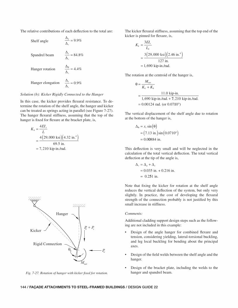
144 / FAÇADE ATTACHMENTS TO STEEL-FRAMED BUILDINGS / DESIGN GUIDE 22
Fig. 7-27. Rotation of hanger with kicker fi xed for rotation.
The relative contributions of each defl ection to the total are:
Shelf angle ΔΔ
a
v
= 9 9. %
Spandrel beam ΔΔ
s
v
= 84 8. %
Hanger rotation ΔΔ
θ
v
= 4 4. %
Hanger elongation ΔΔ
e
v
= 0 9. %
Solution (b): Kicker Rigidly Connected to the Hanger
In this case, the kicker provides fl exural resistance. To de-termine the rotation of the shelf angle, the hanger and kicker can be treated as springs acting in parallel (see Figure 7-27). The hanger fl exural stiffness, assuming that the top of the hanger is fi xed for fl exure at the bracket plate, is,
KEI
Lh
x=
=( )( )
4
4 29 000 4 32
69 5
, .
.
ksi in.
in.
4
kip-in./rad.= 7 210,
The kicker fl exural stiffness, assuming that the top end of the kicker is pinned for fl exure, is,
KEI
Lk
x
k
=
=( )( )
3
3 29 000, ksi 2.46 in.
127 in.
4
kip-in./rad.= 1 690,
The rotation at the centroid of the hanger is,
θ =+
=+
M
K Knet
k h
11 0
1 690
.
,
kip-in.
kip-in./rad. 77 210
0 00124 0 07
,
. .
kip-in./rad.
rad. (or= 110°)
The vertical displacement of the shelf angle due to rotation at the bottom of the hanger is,
Δθ θ= ( )= ( ) °( )=
xi sin
. sin .7 13 0 0710in.
0.000884 in.
This defl ection is very small and will be neglected in the calculation of the total vertical defl ection. The total vertical defl ection at the tip of the angle is,
Δ Δ Δv a s= +==
in. + 0.216 in.
0.2
0 035.
551 in.
Note that fi xing the kicker for rotation at the shelf angle reduces the vertical defl ection of the system, but only very slightly. In practice, the cost of developing the fl exural strength of the connection probably is not justifi ed by this small increase in stiffness.
Comments:
Additional cladding support design steps such as the follow-ing are not included in this example:
• Design of the angle hanger for combined fl exure and tension, considering yielding, lateral-torsional buckling, and leg local buckling for bending about the principal axes.
• Design of the fi eld welds between the shelf angle and the hanger.
• Design of the bracket plate, including the welds to the hanger and spandrel beam.
115-156_DG22_Ch07.indd 144 7/16/08 4:47:09 PM

DESIGN GUIDE 22 / FAÇADE ATTACHMENTS TO STEEL-FRAMED BUILDINGS / 145
• Design of the kicker for combined fl exure and compres-sion, considering yielding, lateral-torsional buckling, and leg local buckling for bending about the principal axes.
• Design of the kicker connection to the bottom fl ange.
In this example the bracket plate is assumed to be rigidly attached to the spandrel beam, and the kickers bracing the bottom fl ange of the spandrel beam are assumed to resist the associated torsion. If kickers to the bottom fl ange of the beam are impractical or not possible, the designer must check the spandrel beam for torsion. Torsion on a wide-fl ange spandrel such as this one is likely to lead to substantial vertical defl ec-tions of the shelf angle. As in previous examples, roll beams can be provided to help resist this torsion. If the attachment of the hanger to the spandrel beam can be detailed so as to im-part no moment to the spandrel (i.e., a hinge), torsion in the spandrel can be eliminated, but the hanger must be designed for reverse-curvature bending. See Figures 7-28 and 7-29.
Example 7.5—Shelf Angle for Brick Veneer Supported by Slab Edge
For the clay brick veneer illustrated in Figure 7-30,
1. Select the angle leg thickness required to support the brick cladding where the maximum vertical defl ection of the horizontal leg is z in.
2. Design the fi eld weld between the top edge of the angle and the pour stop.
3. Select the headed studs to transfer loads from the pour stop into the slab.
4. Design the slab reinforcement to support the cladding and a 6-in. stud back-up wall assembly.
Given:For this example, assume that the following load combina-tions control:
Shelf Angle and Stud Strength: 1.4D Defl ection: D
Slab Strength: 1.2D + 1.6L + 0.8W
Use an L6×4.
The story height, h = 14 ft. The slab thickness, ts = 7½ in. The fl oor construction consists of 4½ in. of 4,000-psi normal-weight concrete on a 3-in. metal fl oor deck parallel to the spandrel (total thickness = 7½ in.). The reinforcing steel yield strength, fy = 60 ksi. The thickness of the slab above the fl utes, tc = 4½ in., and the slab bar clear cover, cc = 1 in. The edge of the slab dimension, leos = 11 in.
Fig. 7-28. Hanger assembly moment diagram with pin at spandrel beam web.
Fig. 7-29. Hanger assembly moment diagram with fi xity at spandrel beam web.
Fig. 7-30. Section of slab edge with shelf angle supporting brick veneer.
115-156_DG22_Ch07.indd 145 7/16/08 4:47:09 PM

146 / FAÇADE ATTACHMENTS TO STEEL-FRAMED BUILDINGS / DESIGN GUIDE 22
The weight of the brick veneer, wb = 40 psf and its thick-ness, tm = 3s in. The cavity width between the exterior face of the vertical leg of the shelf angle and the interior face of the brick, wc = 3 in.
The weight of the stud back-up wall including sheathing, waterproofi ng, and insulation, ws = 10 psf. The eccentricity of the stud back-up with respect to the spandrel centerline, es = 8 in. The stud backup resists a components and cladding wind suction, pw = 25 psf acting away from the building.
Solution 1. Select the angle thickness:Unlike in the previous examples where the shelf angle was supported at discrete locations along the length at hangers, here the shelf angle is supported continuously by welds to the pour stop. See Figure 7-31.
The weight of brick per foot is,
P w hb b=
= ( )=
0 040 14
0 560
.
.
kip/ft ft
kip/ft
2
Try a a-in. angle thickness. The moment of inertia of the angle leg per foot of length is,
Ibt
a =
=( )( )
=
3
3
12
12
120 0527
in./ft in.
in
a
. .. /ft4
The elastic section modulus of the angle leg per foot of length is,
Sbt
a =
=( )( )
=
2
2
6
60 281
12 in./ft in.
in. /ft3
a
.
The plastic section modulus of the angle leg per foot of length is,
Zbt
a =
=( )( )
=
2
2
4
40 422
12 in./ft in.
in. /ft3
a
.
Tide and Krogstad (1993) suggest that the brick should be considered to load the horizontal leg of the shelf angle 2 in. outboard of the interior face of the brick. Basing the analysis of the shelf angle on centerline dimensions, the eccentricity of the brick load with respect to the centerline of the vertical leg of the angle is,
e t wc= + +
= + +
=
2
23
2
a12
in
in.in. in.
3.69 in
.
..
The defl ection at the top of the horizontal leg treating the leg as a rigid cantilever is,
= −( )Δcb
aah
P e
EIl e
=
2
63
0 560 kip/ft 3.69 in. ..
ksi in. /ftin.
4
( )( )( ) ( ) −
2
6 29 000 0 05273 6
, .33 69
0 0119
. .
.
in
in.
⎡⎣ ⎤⎦
=
The stiffening effect of the fi llet is conservatively neglected in this calculation.
The moment on the vertical leg is,
M P ea b=
= ( )=
0 560
2 07
.
.
kip/ft 3.69 in.
kip--in./ftFig. 7-31. Analysis model of shelf angle.
115-156_DG22_Ch07.indd 146 7/16/08 4:47:10 PM

DESIGN GUIDE 22 / FAÇADE ATTACHMENTS TO STEEL-FRAMED BUILDINGS / 147
The rotation due to the moment on the vertical leg is,
θaa av
a
M l
EI=
=( )
3
2 07
3 29 000
.
,
kip-in./ft 4 in.
kksi in. /ft
rad. (or
4( )( )=
0 0527
0 00181
.
. 0.104°)
The rigid body rotation of the horizontal leg is,
Δrb ah alt= −
⎛⎝⎜
⎞⎠⎟
= −⎛⎝⎜
⎞⎠⎟
2
62
sin
sin
θ
in.in.a
00 104
0 0106
.
.
( )= in.
°
The total vertical defl ection of the shelf angle is,
Δt = Δc + Δrb
= 0.0119 in. + 0.0106 in.
= 0.0225 in. ≤ z in. o.k.
For fl exure on the horizontal leg of the angle, the critical section is at the toe of the fi llet (a distance k from the back of the angle).
k = d in.
The bending length is,
lb = (t + wc + 2 in.) – k
= (a in. + 3 in. + 2 in.) – d in.
= 3.00 in.
The required fl exural strength is,
M P lu b b=
= ( )( )1 4
1 4 0 560 3 00
.
. . .kip/ft in.
== 2 35. kip-in./ft
The available fl exural strength is,
( )φb n y a y aM F Z F S= ≤
=
0 90 0 90 1 6
0 90 36
. . .
. ( ksi)(0.4422 in. ft)
0.90(1.6)(36
3/
≤ ksi)(0.281 in. ft)
kip-in./ft 14.6
3/
.= ≤13 7 kkip-in./ft
= kip-in./ft13 7. ≥ Mu
o.k.
Use an L6×4×a.
Solution 2. Design the fi eld weld between the top edge of the angle and the pour stop:Try an intermittent 4-in. fi llet weld with FEXX = 70 ksi. Note that the weld is only required along the top edge of the angle and that no weld is required on the bottom edge because the bottom edge is bearing against the pour stop. This has the added benefi t of requiring only downhand fi eld welds. It may be necessary to mask the top edge of the angle during galvanizing because the zinc from the galvanizing process can compromise the effectiveness of the weld. The designer should determine whether the top edge of the angle and weld-affected zones should be touched-up with zinc-rich primer.
The factored vertical shear along the angle is,
V Pu b=
= ( )=
1 4
1 4 0 560
0 784
.
. .
.
kip/ft
kip/ft
Using the angle leg dimensions as lab = 6 in. and lav = 4 in., the factored horizontal tension force acting outward on the weld is,
H Vl t
lu u
ah m
av
=−⎛
⎝⎜⎞
⎠⎟
=
g
kip/ftin
0 7846
... in.
in.
kip/ft
− ( )⎛
⎝⎜
⎞
⎠⎟
=
g s3
4
0 860.
The resultant shear on the weld is,
F V Hu u u= +
= ( ) + ( )
2 2
2 20 784 0 860. .kip/ft kip/ft
1.16 kips/ft=
The angle between the load and the longitudinal axis of the weld is,
θw = °90
The weld effective throat thickness is,
tw = 0.707w
= 0.707(4 in.)
= 0.177 in.
115-156_DG22_Ch07.indd 147 7/16/08 4:47:10 PM

148 / FAÇADE ATTACHMENTS TO STEEL-FRAMED BUILDINGS / DESIGN GUIDE 22
The fi llet weld nominal strength per Specifi cation Equation J2-5 is,
( )F Fw EXX w= +⎡⎣ ⎤⎦=
0 6 1 0 5
0 6 70
1 5. . sin
.
. θ
ksi(( ) + °( )⎡⎣ ⎤⎦=
1 0 5 90
63 0
1 5. sin
.
.
ksi
The minimum required length of fi llet weld per foot of plate is,
lF
F tw
u
v w w
=
= ( )
φ1 16
0 75 63 0 177
.
. .
kips/ft
ksi inn.
in./ft
( )= 0 139.
Per AISC Specifi cation Section J2.2b, the minimum length for intermittent fi llet welds is the larger of four times the nominal weld size and 1½ in. Thus, the 1½-in. minimum length applies in this case.
Use a 4-in. intermittent fi llet weld 1½-in.-long per foot along the length of the shelf angle.
Solution 3. Design the Headed Studs to Transfer Loads from the Pour Stop into the Slab:In this case, the headed studs must resist vertical shear from the brick as well as the tension component of a couple that results from the eccentricity of the brick. Try 6-in.-long, w-in.-diameter studs along the slab edge.
With each stud placed at mid-depth of the slab, the length of the moment arm between forces in the couple is,
et
Mus=
=
=
27
23 75
111112 in.
in..
The factored tension force on the studs per foot of slab is,
NM
eu
u
Mu
=
=
=
2 35
3 750 627
.
..
kip-in./ft
in.kkip/ft
The factored shear force on the studs per foot of slab is,
Vu = 0.784 kip/ft
Try a 2-ft stud spacing (s = 2 ft). Because the studs are far-ther apart than three times the edge distance (3w in.), group effects need not be considered and the studs can be consid-ered to act separately. From Tables 5-12 and 5-13, the design tensile and shear strengths, φNn and φVn, respectively, for w-in.-diameter headed studs with 6-in. embedment into a 7½-in.-thick normal-weight concrete slab are as listed here.
φNn = 5.37 kips
φVn = 3.38 kips
The tension demand-to-capacity ratio is,
sN
Nu
nφ=
( )
= ≤
2
0 234 1
ft 0.627 kip/ft
5.37 kips
. ..0
The shear demand-to-capacity ratio is,
sV
Vu
nφ=
( )
= ≤
2
0 464 1 0
ft 0.784 kip/ft
3.38 kip
. .
Because these individual demand-to-capacity ratios are greater than 0.20, the interaction of tension and shear must be investigated following ACI 318-05 Equation D-31.
The shear-tension interaction is,
+ =sN
N
sV
Vu
n
u
nφ φ+
= ≤
0 234 0 464
0 698 1 0
. .
. . o.k.
Use one 6-in.-long, w-in.-diameter stud at 2 ft on center.
Note that, in addition to the headed studs, threaded studs as shown in Figure 7-30 should also be provided. These studs are welded to the pour stop and are for erection alignment purposes only.
Solution 4. Design the Slab Reinforcement to Support the Cladding and the Stud Backup Wall:The weight of the concrete is carried by the bent plate and need not be considered in the design of the slab reinforce-ment. Additionally, the fl oor live load moment on the slab cantilever is very small because most of the overhang is covered by the backup wall. In this case, this moment can be neglected.
115-156_DG22_Ch07.indd 148 7/16/08 4:47:11 PM

DESIGN GUIDE 22 / FAÇADE ATTACHMENTS TO STEEL-FRAMED BUILDINGS / 149
The weight of the stud backup wall per foot of slab is,
P w hs s=
= ( )=
kips/ft 14 ft
kip
20 010
0 140
.
. //ft
The factored moment at the centerline of the spandrel is,
Mu = 1.2[Pb (leos + t + wc + 2 in.) + Pses]
= 1.2[0.560 kip/ft (11 in. + a in. + 3 in.
+ 2 in.) + 0.140 kip/ft (8 in.)]
= 11.3 kip-in./ft
The wind suction load on the slab edge is,
N p huw w=
= ( )( )=
0 8
0 8 0 025 14
.
. . kip/ft ft2
00 280. kip/ft
Try #4 reinforcing bars at 16 in. on center. Note that this bar spacing violates the maximum bar spacing for beams and slabs presented in ACI 318-05 Section 10.6.4. The ACI criterion is intended to limit surface cracks in concrete. In this example, it is assumed that the slab will be covered with a fi nished fl oor; therefore, surface cracks are not a concern. If surface cracks along the slab edges are a concern, rein-forcing steel may be added in the form of additional bars that supplement the typical reinforcing steel. It is important, however, that enough of the steel be developed at the critical section.
From Table 5-5, the design fl exural strength of the slab is as follows (assuming that the reinforcement is fully developed at the critical section):
φMns = 25 4. kip-in./ft
The area of steel provided is,
As = 0.150 in.2/ft
The slab bar diameter is,
db = 2 in.
The length of the hooked bar beyond the critical section of the slab (see Figure 7-32) is,
l l cd
h eos cb= − −
= − −
=
2
11 12
in. in.in.
9.75
2
iin.
The development length of #4 hooked bar in 4,000-psi normal-weight concrete is,
ldh = 10 in.
In this particular case, the length of the hook is slightly less than the development length, so the effective steel area must be reduced. Additionally, some of this steel area is re-quired to resist out-of-plane tension loads on the slab edge due to wind loads and the eccentricity of the curtain wall. Hence, the nominal fl exural strength of the slab must be recalculated.
The effective depth from the top of the deck to the reinforc-ing steel is,
= −d td
cb−
= − −
=
12
4 12
3 25
in.
in. in.in.
22
. in.
The effective area of steel in the slab is,
= −Al
lA
N
fse
h
dhs
uw
y
⎛
⎝⎜
⎞
⎠⎟
=
φ
in.
in.
9 75
10
.00 150
0 280
0 90 60.
.
.in. /ft
kip/ft
ksi2 − ( )
⎛
⎝⎜
⎞
⎠⎠⎟
= in. /ft20 141.
By strain compatibility and equilibrium calculations not shown here, es > ey, the steel stress can be taken equal to fy, and the concrete compression block depth is,
aA f
bf
se y
c
=
=( )
0 85
0 141
0 85 12
.
.
.
′in. 60 ksi
in
2
.. ksi
in.
( )( )=
4
0 207.
Fig. 7-32. Slab dimensions for analysis.
115-156_DG22_Ch07.indd 149 7/16/08 4:47:11 PM

150 / FAÇADE ATTACHMENTS TO STEEL-FRAMED BUILDINGS / DESIGN GUIDE 22
Thus,
φ ε
φ φ
= >
= −⎛⎝⎜
⎞⎠⎟
0 9 0 005
2
. ( . )since s
M A f da
ns se y
in. ksi in.2= ( )( ) −0 9 0 141 60 3 250 20
. . .. 77
2
24 0
in.
kip-in./ft >11.3 k
⎛⎝⎜
⎞⎠⎟
= . iip-in./ft o.k.
Comments:
An alternative, less complicated approximation to the cal-culations shown above is as follows. The nominal fl exural strength of the slab is,
φφMns =
=
25 4
0 90
28 2
.
.
.
kip-in./ft
kip-iin./ft
The area of steel provided is,
As = 0.150 in.2/ft
The reduced slab fl exural strength is,
( )
= −Ml
l
N f
AMnsr
h
dh
uw y
sns
⎛
⎝⎜
⎞
⎠⎟
=
1
9 75
/
.
φ
in.
in.
kip/ft) ksi
101
0 280 0 90 60
0 1−
⎡⎣ ⎤⎦( . / .
. 55028 2
26 5
in.kip-in./ft
2
⎡
⎣⎢⎢
⎤
⎦⎥⎥
=
.
. kkip-in./ft
φMnsr = 0.90(26.5 kip-in./ft)
= 23.9 kip-in./ft > 11.3 kip-in./ft o.k.
The area of steel required for direct tension is suffi ciently small that either method provides an acceptable result.
The type of cladding support used in this example pres-ents several diffi culties for construction tolerances, and for that reason, it is not preferred over other means of clad-ding support. Although there may be vertical slotted holes in the vertical leg of the shelf angle, there is substantially less room for vertical adjustment of the shelf angle com-pared with the structures considered in previous examples. Furthermore, the only means to adjust the angle toward or away from the slab edge is to adjust the bent plate to span-drel beam connection since the vertical leg of the angle is welded directly to the pour stop. However, there may be situations in which this type of cladding support is the best solution, particularly where there is no room for kickers be-neath the slab or the shelf angle height is relatively high for architectural reasons.
115-156_DG22_Ch07.indd 150 7/16/08 4:47:11 PM

DESIGN GUIDE 22 / FAÇADE ATTACHMENTS TO STEEL-FRAMED BUILDINGS / 151
Table 7-1. Vertical Deflection at Tip of Shelf Angle, in.
Supporting 10 Vertical Feet of Brick1
AngleThickness,
in.
Spacing of Angle Attachment to Structure, in.
24 30 36 42 48 54 60 66 72
L5x5
5/16 0.0258 0.0329 0.0399 0.0467 0.0534 0.0651 0.0788 0.0949 0.1143/8 0.0151 0.0193 0.0234 0.0274 0.0316 0.0386 0.0468 0.0565 0.0679
7/16(8) 0.00965 0.0123 0.0149 0.0175 0.0204 0.0250 0.0304 0.0368 0.04441/2 0.00653 0.00834 0.0101 0.0119 0.0140 0.0171 0.0209 0.0254 0.03075/8 0.00340 0.00435 0.00527 0.00618 0.00743 0.00917 0.0113 0.0138 0.01683/4 0.00200 0.00256 0.00311 0.00365 0.00448 0.00557 0.00689 0.00851 0.0105
L6x4
(LLH)
5/16 0.0491 0.0624 0.0755 0.0883 0.1008 0.117 0.142 0.171 –3/8 0.0286 0.0364 0.0441 0.0516 0.0589 0.0694 0.0842 0.102 0.122
7/16(8) 0.0182 0.0232 0.0281 0.0328 0.0375 0.0447 0.0544 0.0659 0.07931/2 0.0123 0.0156 0.0189 0.0222 0.0253 0.0305 0.0373 0.0452 0.0547
9/16(8) 0.00870 0.0111 0.0134 0.0157 0.0179 0.0219 0.0268 0.0327 0.03975/8 0.00639 0.00813 0.00985 0.0115 0.0132 0.0163 0.0200 0.0245 0.02993/4 0.00374 0.00477 0.00578 0.00676 0.00793 0.00985 0.0122 0.0151 0.0186
L6x6
5/16 0.0420 0.0538 0.0655 0.0769 0.0881 0.0995 0.119 0.141 0.1673/8 0.0246 0.0316 0.0384 0.0451 0.0517 0.0590 0.0705 0.0837 0.0989
7/16(8) 0.0156 0.0201 0.0245 0.0288 0.0330 0.0379 0.0453 0.0539 0.06381/2 0.0106 0.0136 0.0165 0.0194 0.0223 0.0258 0.0308 0.0367 0.0435
9/16(8) 0.00748 0.00961 0.0117 0.0138 0.0158 0.0184 0.0220 0.0263 0.03125/8 0.00549 0.00705 0.00859 0.0101 0.0116 0.0136 0.0163 0.0195 0.02323/4 0.00322 0.00414 0.00505 0.00594 0.00681 0.00811 0.00977 0.0117 0.0140
L7x4
(LLH)
3/8 0.0433 0.0552 0.0668 0.0781 0.0893 0.100 0.118 0.141 0.1681/2 0.0185 0.0236 0.0286 0.0335 0.0383 0.0430 0.0519 0.0624 0.07465/8 0.00963 0.0123 0.0149 0.0174 0.0199 0.0228 0.0277 0.0335 0.04033/4 0.00564 0.00719 0.00872 0.0102 0.0117 0.0137 0.0167 0.0203 0.0246
L8x4
(LLH)
1/2 0.0261 0.0334 0.0405 0.0474 0.0542 0.0608 0.0689 0.0822 0.09759/16(8) 0.0185 0.0236 0.0286 0.0336 0.0384 0.0430 0.0493 0.0589 0.0701
3/4 0.00795 0.0102 0.0123 0.0145 0.0165 0.0186 0.0220 0.0265 0.0318
L8x6
(LLH)
7/16(8) 0.0345 0.0444 0.0542 0.0638 0.0732 0.0823 0.0913 0.107 0.1251/2 0.0232 0.0300 0.0366 0.0430 0.0494 0.0556 0.0617 0.0726 0.0850
9/16(8) 0.0164 0.0212 0.0258 0.0304 0.0349 0.0393 0.0439 0.0516 0.06055/8 0.0120 0.0155 0.0189 0.0223 0.0256 0.0288 0.0323 0.0380 0.04463/4 0.00702 0.00906 0.0111 0.0130 0.0150 0.0168 0.0191 0.0226 0.0265
L8x6
(LLV)
7/16(8) 0.0138 0.0179 0.0219 0.0258 0.0297 0.0338 0.0399 0.0470 0.05501/2 0.00928 0.0120 0.0148 0.0174 0.0201 0.0229 0.0271 0.0319 0.0374
9/16(8) 0.00656 0.00852 0.0104 0.0123 0.0142 0.0163 0.0193 0.0227 0.02665/8 0.00480 0.00624 0.00765 0.00903 0.0104 0.0120 0.0142 0.0167 0.01973/4 0.00281 0.00365 0.00448 0.00529 0.00609 0.00708 0.00841 0.00994 0.01170
L8x8
1/2 0.0205 0.0267 0.0328 0.0388 0.0447 0.0504 0.0560 0.0644 0.07489/16(8) 0.0145 0.0189 0.0232 0.0275 0.0316 0.0357 0.0397 0.0458 0.0532
5/8 0.0107 0.0139 0.0171 0.0202 0.0232 0.0262 0.0292 0.0339 0.03943/4 0.00622 0.00811 0.0100 0.0118 0.0136 0.0153 0.0171 0.0200 0.0232
Notes:1. Brick is 40 psf, standard clay masonry (35/8 in. thickness).2. Table is based on methodology in Tide and Krogstad (1993).3. Angle material is ASTM A36 steel. 4. Calculations assume that at least two-thirds of the width of the brick veneer bears on horizontal leg of the shelf angle and that the brick load is transmitted
to shelf angle ½-in. outboard of the interior face of brick (Tide and Krogstad, 1993).5. Shims locations are assumed at the anchor rods with height equal to that of the vertical leg of the angle and width of 3 in.6. Angle gage is 2½ in. for 4-in. leg, 3 in. for 5-in. leg, 3½ in. for 6-in. leg, 4 in. for 7-in. leg, and 4½ in. for 8 in. leg.7. Coefficient of friction of 0.2 is used to account for frictional effects between the brick and the shelf angle.8. Note that 7/16-in. and 9/16-in.-thick angles may be difficult to obtain.9. Where no value is given, the angle is overstressed.
115-156_DG22_Ch07.indd 151 7/16/08 4:47:12 PM

152 / FAÇADE ATTACHMENTS TO STEEL-FRAMED BUILDINGS / DESIGN GUIDE 22
Table 7-2. Vertical Deflection at Tip of Shelf Angle, in.
Supporting 12 Vertical Feet of Brick1
AngleThickness,
in.
Spacing of Angle Attachment to Structure, in.
24 30 36 42 48 54 60 66 72
L5x5
5/16 0.0311 0.0397 0.0482 0.0566 0.0648 0.0739 0.0887 0.106 0.1253/8 0.0182 0.0233 0.0283 0.0332 0.0380 0.0438 0.0526 0.0629 0.0748
7/16(8) 0.0116 0.0149 0.0181 0.0212 0.0243 0.0284 0.0342 0.0409 0.04881/2 0.00787 0.0101 0.0122 0.0143 0.0164 0.0194 0.0235 0.0282 0.03375/8 0.00410 0.00524 0.00637 0.00748 0.00857 0.0104 0.0126 0.0153 0.01843/4 0.00241 0.00309 0.00376 0.00441 0.00512 0.00629 0.00769 0.00939 0.0114
L6x4
(LLH)
5/16 0.0591 0.0753 0.0912 0.107 0.122 0.137 - - -3/8 0.0345 0.0440 0.0533 0.0624 0.0714 0.0803 0.0946 0.113 0.134
7/16(8) 0.0219 0.0280 0.0339 0.0398 0.0455 0.0511 0.0611 0.0732 0.08731/2 0.0148 0.0189 0.0229 0.0268 0.0307 0.0346 0.0418 0.0502 0.0601
9/16(8) 0.0105 0.0134 0.0162 0.0190 0.0217 0.0248 0.0300 0.0362 0.04355/8 0.00769 0.00981 0.0119 0.0140 0.0160 0.0184 0.0224 0.0271 0.03283/4 0.00451 0.00576 0.00698 0.00819 0.00938 0.0111 0.0136 0.0166 0.0203
L6x6
5/16 0.0505 0.0649 0.0791 0.0931 0.107 0.120 0.135 0.159 0.1863/8 0.0296 0.0381 0.0464 0.0546 0.0627 0.0706 0.0801 0.0943 0.110
7/16(8) 0.0188 0.0242 0.0296 0.0348 0.0399 0.0450 0.0515 0.0607 0.07121/2 0.0127 0.0164 0.0200 0.0235 0.0270 0.0304 0.0350 0.0413 0.0486
9/16(8) 0.00900 0.0116 0.0141 0.0166 0.0191 0.0215 0.0250 0.0296 0.03485/8 0.00661 0.00850 0.0104 0.0122 0.0140 0.0158 0.0185 0.0219 0.02583/4 0.00388 0.00500 0.00610 0.00718 0.00825 0.00930 0.0111 0.0132 0.0156
L7x4
(LLH)
3/8 0.0521 0.0665 0.0807 0.0946 0.108 0.122 0.135 0.158 -1/2 0.0223 0.0285 0.0346 0.0406 0.0465 0.0522 0.0585 0.0697 0.08265/8 0.0116 0.0148 0.0180 0.0211 0.0242 0.0272 0.0312 0.0373 0.04453/4 0.00679 0.00868 0.0105 0.0124 0.0142 0.0159 0.0187 0.0226 0.0271
L8x4
(LLH)
1/2 0.0315 0.0403 0.0489 0.0574 0.0657 0.0739 0.0819 0.0923 0.1099/16(8) 0.0222 0.0285 0.0346 0.0406 0.0465 0.0523 0.0580 0.0661 0.0780
3/4 0.0096 0.0123 0.0149 0.0175 0.0200 0.0225 0.0250 0.0296 0.0352
L8x6
(LLH)
7/16(8) 0.0415 0.0536 0.0655 0.0772 0.0887 0.100 0.111 0.122 0.1411/2 0.0280 0.0361 0.0442 0.0521 0.0598 0.0675 0.0750 0.0824 0.0957
9/16(8) 0.0197 0.0255 0.0312 0.0368 0.0423 0.0477 0.0530 0.0586 0.06815/8 0.0145 0.0187 0.0228 0.0269 0.0310 0.0349 0.0388 0.0432 0.05023/4 0.00845 0.0109 0.0134 0.0158 0.0181 0.0204 0.0227 0.0256 0.0298
L8x6
(LLV)
7/16(8) 0.0166 0.0215 0.0264 0.0312 0.0360 0.0406 0.0458 0.0534 0.06201/2 0.0112 0.0145 0.0178 0.0211 0.0243 0.0275 0.0311 0.0363 0.0422
9/16(8) 0.00790 0.0103 0.0126 0.0149 0.0172 0.0194 0.0221 0.0258 0.03005/8 0.00578 0.00752 0.00923 0.0109 0.0126 0.0142 0.0163 0.0190 0.02213/4 0.00338 0.00440 0.00541 0.00640 0.00737 0.00834 0.00963 0.0113 0.0132
L8x8
1/2 0.0247 0.0322 0.0396 0.0469 0.0541 0.0611 0.0681 0.0749 0.08499/16(8) 0.0175 0.0228 0.0280 0.0332 0.0383 0.0433 0.0482 0.0530 0.0604
5/8 0.0128 0.0167 0.0206 0.0244 0.0281 0.0318 0.0354 0.0390 0.04473/4 0.00748 0.00978 0.0120 0.0143 0.0164 0.0186 0.0207 0.0229 0.0264
Notes:1. Brick is 40 psf, standard clay masonry (35/8 in. thickness).2. Table is based on methodology in Tide and Krogstad (1993).3. Angle material is ASTM A36 steel.4. Calculations assume that at least two-thirds of the width of the brick veneer bears on horizontal leg of the shelf angle and that the brick load is transmitted
to shelf angle ½-in. outboard of the interior face of brick (Tide and Krogstad, 1993).5. Shims locations are assumed at the anchor rods with height equal to that of the vertical leg of the angle and width of 3 in.6. Angle gage is 2½ in. for 4-in. leg, 3 in. for 5-in. leg, 3½ in. for 6-in. leg, 4 in. for 7-in. leg, and 4½ in. for 8 in. leg.7. Coefficient of friction of 0.2 is used to account for frictional effects between the brick and the shelf angle.8. Note that 7/16-in. and 9/16-in.-thick angles may be difficult to obtain.9. Where no value is given, the angle is overstressed.
115-156_DG22_Ch07.indd 152 7/16/08 4:47:12 PM

DESIGN GUIDE 22 / FAÇADE ATTACHMENTS TO STEEL-FRAMED BUILDINGS / 153
Table 7-3. Vertical Deflection at Tip of Shelf Angle, in.
Supporting 14 Vertical Feet of Brick1
AngleThickness,
in.
Spacing of Angle Attachment to Structure, in.
24 30 36 42 48 54 60 66 72
L5x5
5/16 0.0364 0.0465 0.0565 0.0664 0.0762 0.0858 0.0985 0.117 -3/8 0.0213 0.0273 0.0331 0.0389 0.0446 0.0503 0.0584 0.0693 0.0818
7/16(8) 0.0136 0.0174 0.0212 0.0249 0.0285 0.0321 0.0379 0.0450 0.05331/2 0.00921 0.0118 0.0143 0.0168 0.0193 0.0218 0.0260 0.0310 0.03685/8 0.00480 0.00614 0.00747 0.00878 0.0101 0.0116 0.0139 0.0167 0.02003/4 0.00282 0.00362 0.00440 0.00518 0.00594 0.00701 0.00849 0.0103 0.0124
L6x4
(LLH)
5/16 0.0691 0.0882 0.107 0.126 0.144 - - - -3/8 0.0404 0.0515 0.0625 0.0733 0.0840 0.0945 0.1050 0.124 -
7/16(8) 0.0257 0.0328 0.0398 0.0467 0.0535 0.0602 0.0677 0.0805 0.09531/2 0.0173 0.0221 0.0268 0.0315 0.0361 0.0406 0.0463 0.0552 0.0656
9/16(8) 0.0123 0.0157 0.0190 0.0223 0.0256 0.0288 0.0332 0.0398 0.04745/8 0.00900 0.0115 0.0140 0.0164 0.0188 0.0211 0.0248 0.0297 0.03563/4 0.00528 0.00674 0.00819 0.00961 0.0110 0.0124 0.0150 0.0182 0.0219
L6x6
5/16 0.0591 0.0760 0.0928 0.109 0.126 0.142 0.157 - -3/8 0.0346 0.0446 0.0544 0.0641 0.0737 0.0831 0.0924 0.1049 0.122
7/16(8) 0.0220 0.0284 0.0346 0.0408 0.0469 0.0529 0.0589 0.0675 0.07861/2 0.0149 0.0192 0.0234 0.0276 0.0317 0.0358 0.0398 0.0459 0.0536
9/16(8) 0.0105 0.0136 0.0166 0.0195 0.0224 0.0253 0.0282 0.0328 0.03845/8 0.00773 0.0100 0.0122 0.0143 0.0165 0.0186 0.0207 0.0243 0.02853/4 0.00454 0.00585 0.00715 0.00843 0.00969 0.0109 0.0124 0.0146 0.0171
L7x4
(LLH)
3/8 0.0610 0.0779 0.0946 0.111 0.127 0.143 - - -1/2 0.0261 0.0334 0.0406 0.0477 0.0546 0.0615 0.0682 0.0770 0.09065/8 0.0136 0.0174 0.0211 0.0248 0.0284 0.0320 0.0355 0.0412 0.04873/4 0.00794 0.0102 0.0124 0.0145 0.0166 0.0187 0.0208 0.0248 0.0296
L8x4
(LLH)
1/2 0.0368 0.0471 0.0573 0.0674 0.0773 0.0870 0.0966 0.106 0.1209/16(8) 0.0260 0.0333 0.0406 0.0477 0.0547 0.0616 0.0684 0.0750 0.0858
3/4 0.0112 0.0143 0.0175 0.0205 0.0236 0.0265 0.0295 0.0328 0.0386
L8x6
(LLH)
7/16(8) 0.0485 0.0627 0.0767 0.0905 0.104 0.118 0.131 0.144 0.1571/2 0.0327 0.0423 0.0517 0.0611 0.0703 0.0793 0.0883 0.0971 0.106
9/16(8) 0.0231 0.0299 0.0366 0.0432 0.0497 0.0561 0.0624 0.0686 0.07575/8 0.0169 0.0219 0.0268 0.0316 0.0364 0.0411 0.0457 0.0503 0.05583/4 0.00987 0.0128 0.0157 0.0185 0.0213 0.0240 0.0268 0.0294 0.0331
L8x6
(LLV)
7/16(8) 0.0194 0.0252 0.0309 0.0366 0.0422 0.0478 0.0533 0.0598 0.06901/2 0.0131 0.0170 0.0209 0.0247 0.0285 0.0323 0.0360 0.0406 0.0469
9/16(8) 0.00923 0.0120 0.0148 0.0175 0.0202 0.0228 0.0254 0.0289 0.03345/8 0.00676 0.00880 0.0108 0.0128 0.0148 0.0167 0.0186 0.0213 0.02463/4 0.00396 0.00515 0.00634 0.00750 0.00866 0.00980 0.0109 0.0126 0.0146
L8x8
1/2 0.0289 0.0377 0.0464 0.0550 0.0635 0.0719 0.0801 0.0883 0.09639/16(8) 0.0204 0.0266 0.0328 0.0389 0.0449 0.0509 0.0567 0.0625 0.0681
5/8 0.0150 0.0196 0.0241 0.0286 0.0330 0.0374 0.0417 0.0459 0.05013/4 0.00875 0.0114 0.0141 0.0167 0.0193 0.0219 0.0244 0.0269 0.0295
Notes:1. Brick is 40 psf, standard clay masonry (35/8 in. thickness).2. Table is based on methodology in Tide and Krogstad (1993).3. Angle material is ASTM A36 steel.4. Calculations assume that at least two-thirds of the width of the brick veneer bears on horizontal leg of the shelf angle and that the brick load is transmitted
to shelf angle ½-in. outboard of the interior face of brick (Tide and Krogstad, 1993).5. Shims locations are assumed at the anchor rods with height equal to that of the vertical leg of the angle and width of 3 in.6. Angle gage is 2½ in. for 4-in. leg, 3 in. for 5-in. leg, 3½ in. for 6-in. leg, 4 in. for 7-in. leg, and 4½ in. for 8 in. leg.7. Coefficient of friction of 0.2 is used to account for frictional effects between the brick and the shelf angle.8. Note that 7/16-in. and 9/16-in.-thick angles may be difficult to obtain.9. Where no value is given, the angle is overstressed.
115-156_DG22_Ch07.indd 153 7/16/08 4:47:12 PM
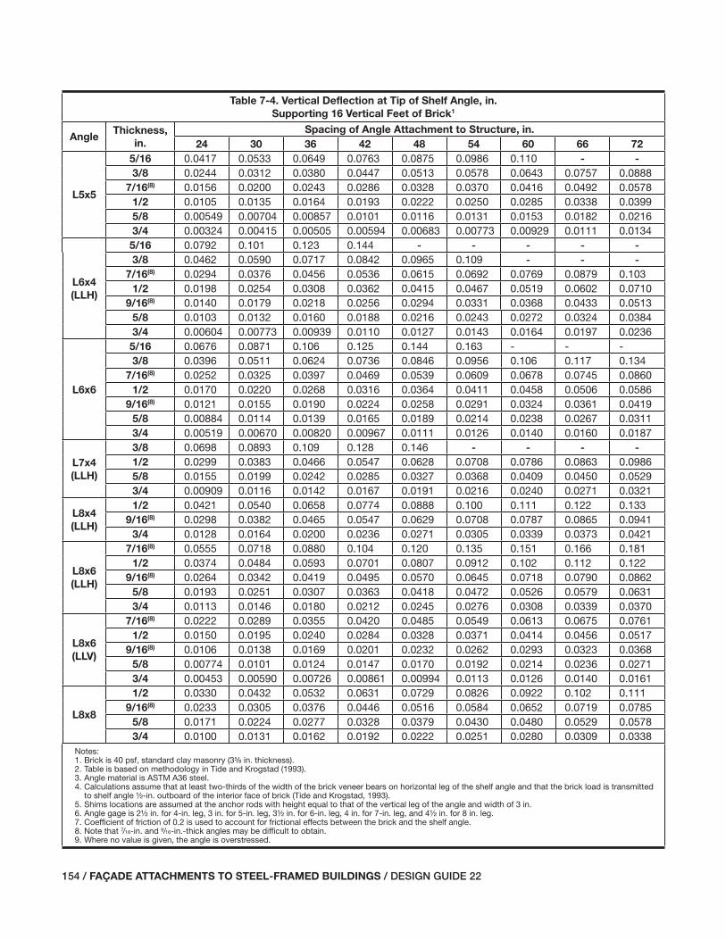
154 / FAÇADE ATTACHMENTS TO STEEL-FRAMED BUILDINGS / DESIGN GUIDE 22
Table 7-4. Vertical Deflection at Tip of Shelf Angle, in.
Supporting 16 Vertical Feet of Brick1
AngleThickness,
in.
Spacing of Angle Attachment to Structure, in.
24 30 36 42 48 54 60 66 72
L5x5
5/16 0.0417 0.0533 0.0649 0.0763 0.0875 0.0986 0.110 - -3/8 0.0244 0.0312 0.0380 0.0447 0.0513 0.0578 0.0643 0.0757 0.0888
7/16(8) 0.0156 0.0200 0.0243 0.0286 0.0328 0.0370 0.0416 0.0492 0.05781/2 0.0105 0.0135 0.0164 0.0193 0.0222 0.0250 0.0285 0.0338 0.03995/8 0.00549 0.00704 0.00857 0.0101 0.0116 0.0131 0.0153 0.0182 0.02163/4 0.00324 0.00415 0.00505 0.00594 0.00683 0.00773 0.00929 0.0111 0.0134
L6x4
(LLH)
5/16 0.0792 0.101 0.123 0.144 - - - - -3/8 0.0462 0.0590 0.0717 0.0842 0.0965 0.109 - - -
7/16(8) 0.0294 0.0376 0.0456 0.0536 0.0615 0.0692 0.0769 0.0879 0.1031/2 0.0198 0.0254 0.0308 0.0362 0.0415 0.0467 0.0519 0.0602 0.0710
9/16(8) 0.0140 0.0179 0.0218 0.0256 0.0294 0.0331 0.0368 0.0433 0.05135/8 0.0103 0.0132 0.0160 0.0188 0.0216 0.0243 0.0272 0.0324 0.03843/4 0.00604 0.00773 0.00939 0.0110 0.0127 0.0143 0.0164 0.0197 0.0236
L6x6
5/16 0.0676 0.0871 0.106 0.125 0.144 0.163 - - -3/8 0.0396 0.0511 0.0624 0.0736 0.0846 0.0956 0.106 0.117 0.134
7/16(8) 0.0252 0.0325 0.0397 0.0469 0.0539 0.0609 0.0678 0.0745 0.08601/2 0.0170 0.0220 0.0268 0.0316 0.0364 0.0411 0.0458 0.0506 0.0586
9/16(8) 0.0121 0.0155 0.0190 0.0224 0.0258 0.0291 0.0324 0.0361 0.04195/8 0.00884 0.0114 0.0139 0.0165 0.0189 0.0214 0.0238 0.0267 0.03113/4 0.00519 0.00670 0.00820 0.00967 0.0111 0.0126 0.0140 0.0160 0.0187
L7x4
(LLH)
3/8 0.0698 0.0893 0.109 0.128 0.146 - - - -1/2 0.0299 0.0383 0.0466 0.0547 0.0628 0.0708 0.0786 0.0863 0.09865/8 0.0155 0.0199 0.0242 0.0285 0.0327 0.0368 0.0409 0.0450 0.05293/4 0.00909 0.0116 0.0142 0.0167 0.0191 0.0216 0.0240 0.0271 0.0321
L8x4
(LLH)
1/2 0.0421 0.0540 0.0658 0.0774 0.0888 0.100 0.111 0.122 0.1339/16(8) 0.0298 0.0382 0.0465 0.0547 0.0629 0.0708 0.0787 0.0865 0.0941
3/4 0.0128 0.0164 0.0200 0.0236 0.0271 0.0305 0.0339 0.0373 0.0421
L8x6
(LLH)
7/16(8) 0.0555 0.0718 0.0880 0.104 0.120 0.135 0.151 0.166 0.1811/2 0.0374 0.0484 0.0593 0.0701 0.0807 0.0912 0.102 0.112 0.122
9/16(8) 0.0264 0.0342 0.0419 0.0495 0.0570 0.0645 0.0718 0.0790 0.08625/8 0.0193 0.0251 0.0307 0.0363 0.0418 0.0472 0.0526 0.0579 0.06313/4 0.0113 0.0146 0.0180 0.0212 0.0245 0.0276 0.0308 0.0339 0.0370
L8x6
(LLV)
7/16(8) 0.0222 0.0289 0.0355 0.0420 0.0485 0.0549 0.0613 0.0675 0.07611/2 0.0150 0.0195 0.0240 0.0284 0.0328 0.0371 0.0414 0.0456 0.0517
9/16(8) 0.0106 0.0138 0.0169 0.0201 0.0232 0.0262 0.0293 0.0323 0.03685/8 0.00774 0.0101 0.0124 0.0147 0.0170 0.0192 0.0214 0.0236 0.02713/4 0.00453 0.00590 0.00726 0.00861 0.00994 0.0113 0.0126 0.0140 0.0161
L8x8
1/2 0.0330 0.0432 0.0532 0.0631 0.0729 0.0826 0.0922 0.102 0.1119/16(8) 0.0233 0.0305 0.0376 0.0446 0.0516 0.0584 0.0652 0.0719 0.0785
5/8 0.0171 0.0224 0.0277 0.0328 0.0379 0.0430 0.0480 0.0529 0.05783/4 0.0100 0.0131 0.0162 0.0192 0.0222 0.0251 0.0280 0.0309 0.0338
Notes:1. Brick is 40 psf, standard clay masonry (35/8 in. thickness).2. Table is based on methodology in Tide and Krogstad (1993).3. Angle material is ASTM A36 steel.4. Calculations assume that at least two-thirds of the width of the brick veneer bears on horizontal leg of the shelf angle and that the brick load is transmitted
to shelf angle ½-in. outboard of the interior face of brick (Tide and Krogstad, 1993).5. Shims locations are assumed at the anchor rods with height equal to that of the vertical leg of the angle and width of 3 in.6. Angle gage is 2½ in. for 4-in. leg, 3 in. for 5-in. leg, 3½ in. for 6-in. leg, 4 in. for 7-in. leg, and 4½ in. for 8 in. leg.7. Coefficient of friction of 0.2 is used to account for frictional effects between the brick and the shelf angle.8. Note that 7/16-in. and 9/16-in.-thick angles may be difficult to obtain.9. Where no value is given, the angle is overstressed.
115-156_DG22_Ch07.indd 154 7/16/08 4:47:13 PM
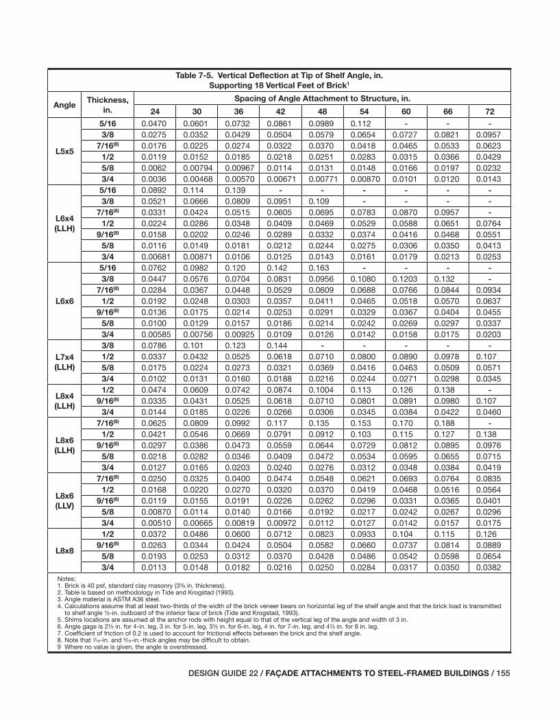
DESIGN GUIDE 22 / FAÇADE ATTACHMENTS TO STEEL-FRAMED BUILDINGS / 155
Table 7-5. Vertical Deflection at Tip of Shelf Angle, in.
Supporting 18 Vertical Feet of Brick1
AngleThickness,
in.
Spacing of Angle Attachment to Structure, in.
24 30 36 42 48 54 60 66 72
L5x5
5/16 0.0470 0.0601 0.0732 0.0861 0.0989 0.112 - - -3/8 0.0275 0.0352 0.0429 0.0504 0.0579 0.0654 0.0727 0.0821 0.0957
7/16(8) 0.0176 0.0225 0.0274 0.0322 0.0370 0.0418 0.0465 0.0533 0.06231/2 0.0119 0.0152 0.0185 0.0218 0.0251 0.0283 0.0315 0.0366 0.04295/8 0.0062 0.00794 0.00967 0.0114 0.0131 0.0148 0.0166 0.0197 0.02323/4 0.0036 0.00468 0.00570 0.00671 0.00771 0.00870 0.0101 0.0120 0.0143
L6x4
(LLH)
5/16 0.0892 0.114 0.139 - - - - - -3/8 0.0521 0.0666 0.0809 0.0951 0.109 - - - -
7/16(8) 0.0331 0.0424 0.0515 0.0605 0.0695 0.0783 0.0870 0.0957 -1/2 0.0224 0.0286 0.0348 0.0409 0.0469 0.0529 0.0588 0.0651 0.0764
9/16(8) 0.0158 0.0202 0.0246 0.0289 0.0332 0.0374 0.0416 0.0468 0.05515/8 0.0116 0.0149 0.0181 0.0212 0.0244 0.0275 0.0306 0.0350 0.04133/4 0.00681 0.00871 0.0106 0.0125 0.0143 0.0161 0.0179 0.0213 0.0253
L6x6
5/16 0.0762 0.0982 0.120 0.142 0.163 - - - -3/8 0.0447 0.0576 0.0704 0.0831 0.0956 0.1080 0.1203 0.132 -
7/16(8) 0.0284 0.0367 0.0448 0.0529 0.0609 0.0688 0.0766 0.0844 0.09341/2 0.0192 0.0248 0.0303 0.0357 0.0411 0.0465 0.0518 0.0570 0.0637
9/16(8) 0.0136 0.0175 0.0214 0.0253 0.0291 0.0329 0.0367 0.0404 0.04555/8 0.0100 0.0129 0.0157 0.0186 0.0214 0.0242 0.0269 0.0297 0.03373/4 0.00585 0.00756 0.00925 0.0109 0.0126 0.0142 0.0158 0.0175 0.0203
L7x4
(LLH)
3/8 0.0786 0.101 0.123 0.144 - - - - -1/2 0.0337 0.0432 0.0525 0.0618 0.0710 0.0800 0.0890 0.0978 0.1075/8 0.0175 0.0224 0.0273 0.0321 0.0369 0.0416 0.0463 0.0509 0.05713/4 0.0102 0.0131 0.0160 0.0188 0.0216 0.0244 0.0271 0.0298 0.0345
L8x4
(LLH)
1/2 0.0474 0.0609 0.0742 0.0874 0.1004 0.113 0.126 0.138 -9/16(8) 0.0335 0.0431 0.0525 0.0618 0.0710 0.0801 0.0891 0.0980 0.107
3/4 0.0144 0.0185 0.0226 0.0266 0.0306 0.0345 0.0384 0.0422 0.0460
L8x6
(LLH)
7/16(8) 0.0625 0.0809 0.0992 0.117 0.135 0.153 0.170 0.188 -1/2 0.0421 0.0546 0.0669 0.0791 0.0912 0.103 0.115 0.127 0.138
9/16(8) 0.0297 0.0386 0.0473 0.0559 0.0644 0.0729 0.0812 0.0895 0.09765/8 0.0218 0.0282 0.0346 0.0409 0.0472 0.0534 0.0595 0.0655 0.07153/4 0.0127 0.0165 0.0203 0.0240 0.0276 0.0312 0.0348 0.0384 0.0419
L8x6
(LLV)
7/16(8) 0.0250 0.0325 0.0400 0.0474 0.0548 0.0621 0.0693 0.0764 0.08351/2 0.0168 0.0220 0.0270 0.0320 0.0370 0.0419 0.0468 0.0516 0.0564
9/16(8) 0.0119 0.0155 0.0191 0.0226 0.0262 0.0296 0.0331 0.0365 0.04015/8 0.00870 0.0114 0.0140 0.0166 0.0192 0.0217 0.0242 0.0267 0.02963/4 0.00510 0.00665 0.00819 0.00972 0.0112 0.0127 0.0142 0.0157 0.0175
L8x8
1/2 0.0372 0.0486 0.0600 0.0712 0.0823 0.0933 0.104 0.115 0.1269/16(8) 0.0263 0.0344 0.0424 0.0504 0.0582 0.0660 0.0737 0.0814 0.0889
5/8 0.0193 0.0253 0.0312 0.0370 0.0428 0.0486 0.0542 0.0598 0.06543/4 0.0113 0.0148 0.0182 0.0216 0.0250 0.0284 0.0317 0.0350 0.0382
Notes:1. Brick is 40 psf, standard clay masonry (35/8 in. thickness).2. Table is based on methodology in Tide and Krogstad (1993).3. Angle material is ASTM A36 steel.4. Calculations assume that at least two-thirds of the width of the brick veneer bears on horizontal leg of the shelf angle and that the brick load is transmitted
to shelf angle ½-in. outboard of the interior face of brick (Tide and Krogstad, 1993).5. Shims locations are assumed at the anchor rods with height equal to that of the vertical leg of the angle and width of 3 in.6. Angle gage is 2½ in. for 4-in. leg, 3 in. for 5-in. leg, 3½ in. for 6-in. leg, 4 in. for 7-in. leg, and 4½ in. for 8 in. leg.7. Coefficient of friction of 0.2 is used to account for frictional effects between the brick and the shelf angle.8. Note that 7/16-in. and 9/16-in.-thick angles may be difficult to obtain.9 Where no value is given, the angle is overstressed.
115-156_DG22_Ch07.indd 155 7/16/08 4:47:14 PM

156 / FAÇADE ATTACHMENTS TO STEEL-FRAMED BUILDINGS / DESIGN GUIDE 22
115-156_DG22_Ch07.indd 156 7/16/08 4:47:14 PM

DESIGN GUIDE 22 / FAÇADE ATTACHMENTS TO STEEL-FRAMED BUILDINGS / 157
Chapter 8PRECAST CONCRETE WALL PANELS
8.1 GENERAL DESCRIPTION OF PRECAST CONCRETE WALL PANEL SYSTEMS
Precast concrete wall panels have many applications, in-cluding those where the concrete panel is a structural load bearing element. This design guide, however, addresses only those applications where the concrete wall panels are used as a curtain wall supported by a steel frame, where each panel is supported from the structure and does not interact with the primary building structure or become an unintended load path for either gravity or lateral loads. In most applications, panels may be removed individually without affecting the support of adjacent panels. Predominantly, panels used in curtain wall applications are limited in height to the fl oor-to-fl oor dimension (although the joints between panels may not coincide with the elevations of the fl oors) and limited in width to the width of a structural bay. Some panels are not as large as a full story height and a full bay width, but rather may be vertical strips, horizontal strips, panels with punched win-dow openings, or spandrels, mullions, or column covers.
Another application addressed in this design guide in-volves panels supported on the foundation wall with the steel building structure providing only lateral support for out-of-plane loads. Such wall panel units may be stacked so that lower wall panels support the weight of upper panels. The larger dimension of these panels tends to be vertical and at least one story high.
Precast concrete panels are either solid concrete panels or sandwich panels, which have a layer of rigid insulation “sandwiched” between an exterior layer of architectural concrete and an interior layer of concrete that serves as the structural back-up. The sandwich panel is manufactured so that the two layers of concrete are tied together and the ex-terior layer is supported both vertically and laterally by the back-up panel. The back-up panel is supported by the pri-mary building structure.
Both panel types function as barrier walls, and cracking must be limited to hairline widths to prevent moisture pen-etration through the panel. The joints between panels are the key to successful moisture protection performance of the wall system. The system uses sealants to make the joints watertight, and movement at these joints must be considered when designing the support and attachment of the panels. The life expectancy of the sealant joint depends on, among other factors, the number of movement cycles and the mag-nitude of the movement as a percentage of joint width.
When solid wall panels are used, insulation is affi xed to the interior surface, or an independent insulated partition wall is placed inside the concrete panel.
8.2 STRATEGIES FOR SUPPORT OF PRECAST CONCRETE WALL PANELS
The most important strategy for support of precast concrete panels is to support the weight of each panel by no more than two load bearing connections. This keeps the support for gravity loads determinate so that calculation of the reac-tions is independent of the support fl exibility. A panel should not be supported at three points because there is no practical way to erect the panels and ensure that the load at each bear-ing connection (one at each end and one in the middle) is as assumed in design. For example, if the panel is initially set on shims at one of the ends and in the middle, the middle support will receive more than the 62.5 percent of the load assumed for the center support of the two-span continuous condition. When the third support is eventually shimmed, the load sharing of the supports will be changed. Shimming to a snug-tight condition will not change the initial distri-bution signifi cantly. Over-shimming may lift the support such that the center support is unloaded and each end will receive 50 percent of the weight. Even if careful shimming with load monitoring could be used to distribute the weight of the panel as assumed in the analysis, movement of any support location, such as that caused by defl ection of a beam due to fl oor live loads, would once again change the support reactions. Besides making it diffi cult—if not impossible—to know the bearing reactions for design of the connections, more than two supports makes it impractical to know the fi nal force distribution in the panel for proper design of the panel itself.
Another important strategy for the support of precast pan-els is accommodating volume change of the panels. Volume change will occur due to changes in temperature and, to a lesser degree, moisture. Drying shrinkage of the concrete panel will also have an impact, depending on its mix design and when it is erected relative to its production. To accom-modate volume change, one of the bearing supports should allow lateral movement parallel to the width of the panel. This is commonly done with inserts or attachment clips. The other bearing connection transfers all the lateral forces par-allel to the panel width into the support structure. All con-nections to the primary structure other than the two bearing
157-174_DG22_Ch08.indd 157 7/16/08 4:51:06 PM
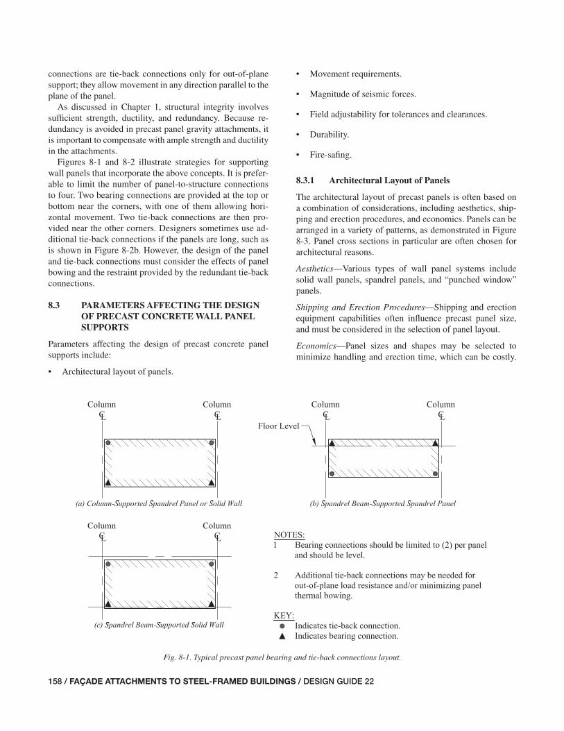
158 / FAÇADE ATTACHMENTS TO STEEL-FRAMED BUILDINGS / DESIGN GUIDE 22
Fig. 8-1. Typical precast panel bearing and tie-back connections layout.
connections are tie-back connections only for out-of-plane support; they allow movement in any direction parallel to the plane of the panel.
As discussed in Chapter 1, structural integrity involves suffi cient strength, ductility, and redundancy. Because re-dundancy is avoided in precast panel gravity attachments, it is important to compensate with ample strength and ductility in the attachments.
Figures 8-1 and 8-2 illustrate strategies for supporting wall panels that incorporate the above concepts. It is prefer-able to limit the number of panel-to-structure connections to four. Two bearing connections are provided at the top or bottom near the corners, with one of them allowing hori-zontal movement. Two tie-back connections are then pro-vided near the other corners. Designers sometimes use ad-ditional tie-back connections if the panels are long, such as is shown in Figure 8-2b. However, the design of the panel and tie-back connections must consider the effects of panel bowing and the restraint provided by the redundant tie-back connections.
8.3 PARAMETERS AFFECTING THE DESIGN OF PRECAST CONCRETE WALL PANEL SUPPORTS
Parameters affecting the design of precast concrete panel supports include:
• Architectural layout of panels.
• Movement requirements.
• Magnitude of seismic forces.
• Field adjustability for tolerances and clearances.
• Durability.
• Fire-safi ng.
8.3.1 Architectural Layout of Panels
The architectural layout of precast panels is often based on a combination of considerations, including aesthetics, ship-ping and erection procedures, and economics. Panels can be arranged in a variety of patterns, as demonstrated in Figure 8-3. Panel cross sections in particular are often chosen for architectural reasons.
Aesthetics—Various types of wall panel systems include solid wall panels, spandrel panels, and “punched window” panels.
Shipping and Erection Procedures—Shipping and erection equipment capabilities often infl uence precast panel size, and must be considered in the selection of panel layout.
Economics—Panel sizes and shapes may be selected to minimize handling and erection time, which can be costly.
157-174_DG22_Ch08.indd 158 7/16/08 4:51:06 PM

DESIGN GUIDE 22 / FAÇADE ATTACHMENTS TO STEEL-FRAMED BUILDINGS / 159
Fig. 8-2. Typical precast panel load supports.
Fig. 8-3. Typical arrangement of precast concrete panels.(Taken from reference “Architectural Precast Concrete,” Second Edition, PCI.
Used with permission Precast/Prestressed Concrete Institute.)
157-174_DG22_Ch08.indd 159 7/16/08 4:51:07 PM
160 / FAÇADE ATTACHMENTS TO STEEL-FRAMED BUILDINGS / DESIGN GUIDE 22
commodating this movement is to anchor the panels to the primary structure in such a manner that in-plane forces are resisted at only one anchor per panel. All other connections are detailed with allowance for in-plane movement. This is demonstrated in Figure 8-2b through the use of a shear plate, but it could also be achieved at one of the bearing connec-tions. In high-seismic applications, movements are larger, and special attention may be required to allow for these deformations without inducing unanticipated force transfer in the panel.
Out-of-Plane Movement—The interior-to-exterior tempera-ture differential can cause out-of-plane thermal bowing, particularly as the thickness of precast concrete panels de-creases. Seismic forces can also cause bowing. Additional attachments to the primary structure are sometimes used to control bowing on long spandrel panels, and panel designs must consider the effects of this restraint on panel crack-ing. The restraining forces will be computed by the specialty structural engineer (SSE) designing the attachments. Al-though the magnitudes of these forces are usually not sig-nifi cant for the design of the primary structure, large forces may require consideration.
8.3.3 Magnitude of Seismic Forces
Precast concrete panels are one of the heavier façade systems and, therefore, possess larger seismic forces than most other systems. Greater allowances must be made in connections for seismic movement, and greater loads are imposed on the primary building structure with precast panels. The effects of these loads are accentuated by their typical eccentric load-ing to the support structure.
A common method of transferring large in-plane seismic loads is through the use of a shear plate connection. Figure 8-4 illustrates a common seismic shear plate detail for high seismic forces.
8.3.4 Field Adjustability for Tolerances and Clearances
As demonstrated in Chapter 7 with masonry cavity wall sys-tems, precast concrete panel systems also require fi eld ad-justments for fabrication and erection tolerances of the steel frame. The magnitude of the necessary adjustments depends on the number of stories and the span lengths as discussed in Chapter 4. Suggested adjustments include:
• Means to adjust the slab edge in or out relative to the spandrel beam.
• Means to adjust the location of the precast panels in or out relative to the slab edge.
• Means to adjust the location of the precast panels up or down relative to the slab edge.
An economically effi cient panel can be tilted immediately after its forms are stripped, and stored in the yard in a posi-tion similar to its fi nal erected and adjusted position on the structure. Panels having similar connections increase overall effi ciency. The workers’ familiarity with the connections also results in increased productivity.
Panel layouts that are repetitive in fi nish, shape, and size will often also prove more economical.
8.3.2 Movement Requirements
Vertical and lateral movements, in-plane drift of the steel frame, and out-of-plane movements all require consideration.
Vertical and Lateral Movements—The supporting steel and attachments must accommodate the vertical and lateral move-ments of the precast panels due to volume change, which is caused by variations in temperature, creep, and shrinkage. Drying shrinkage and creep in precast concrete members continue to occur after erection and should be accounted for in connection and clearance detailing. Additionally, tem-perature differential between the interior of the building and the exterior may cause bowing of the precast panel.
• Design movement at horizontal soft joints: Horizontal soft joints must accommodate the movement due to the relative defl ections of upper and lower fl oor structures, as well as the movement due to thermal and moisture volume changes in the precast panels. The sum of the movement accommodated by the soft joint will be approximately 25 to 50 percent of the soft-joint size, depending on sealant materials and sealant bond, to account for sealant com-pressibility and extensibility. Where window frames are attached to precast panels, the effects of panel movement on the window should be considered.
• Stiffness of supporting structure: The designer must provide enough stiffness to mitigate cracking of the precast panel due to support defl ection. There is no in-dustry rule of thumb for defl ection criterion as there is with masonry cavity wall systems because each precast panel system behaves differently. The structural engineer of record (SER) must consider the defl ection specifi c to the particular precast system and panel layout. Exces-sive defl ection of a supporting spandrel beam can lead to translation and rotation of individual precast panels. The spandrel stiffness will often be controlled by the accept-able horizontal soft-joint size.
In-Plane Drift of the Steel Frame—The support and attach-ment details must allow the structural steel frame of the pri-mary structure to undergo its design drift without restraint from the precast panels. As the structure undergoes drift, the upper fl oor moves laterally relative to the lower fl oor. In regions of low seismicity, the common strategy for ac-
157-174_DG22_Ch08.indd 160 7/16/08 4:51:07 PM

DESIGN GUIDE 22 / FAÇADE ATTACHMENTS TO STEEL-FRAMED BUILDINGS / 161
set so they run by the edge of slab. A clearance between the slab edge and panels is required to accommodate erection tolerances, and fi re-safi ng must be used to fi ll this gap.
If all of the steel frame erection tolerances are accommo-dated in the adjustment of the slab edge, the clearance is required only to accommodate the erection tolerance of the precast panels. If only part of the steel frame erection toler-ance is accommodated in the adjustment of the slab edge, the clearance must also accommodate the balance.
Designers should consider the cost benefi t of providing more slab edge adjustment and less clearance to reduce the amount of required fi re-safi ng.
8.4 DESIGN RESPONSIBILITIES FOR PRECAST CONCRETE WALL PANELS
As discussed in Chapter 3, it is important that the design team understands the design responsibilities for the support of precast concrete walls. Contracts can defi ne the design responsibilities for each project, and one approach com-monly found on projects with precast concrete wall panels is discussed in the following text.
Architect—The architect normally has responsibility for the following:
• The selection of the precast concrete panel fi nish, shape, and size.
• Means to adjust the location of the attachments both ver-tically and horizontally.
A common method of providing vertical adjustment is through the use of shim plates. Care must be taken in the use of shims, as improperly designed shims can hinder move-ment and create unintended load paths. Leveling bolts tend to be more costly, but may be used in lieu of shims to save time in erection. Figure 8-5 demonstrates the typical use of these methods. The use of erection bolts in slotted holes with fi eld welding is a common mechanism for achieving the nec-essary horizontal fi eld adjustments.
8.3.5 Durability
Because the typical precast concrete panel façade system does not include a waterproof membrane, it is important that consideration be given to the moisture protection of the panel attachments. Designers should consider protective coatings, such as hot-dip galvanizing or zinc-rich paint for these elements. However, designers do not typically specify a protective coating for the primary structure for moisture from the exterior.
8.3.6 Fire-Safi ng
Fire-safi ng is required between the slab edge and the back of the precast panels, when precast concrete wall panels are
Fig. 8-4. Seismic shear plate connection to spandrel. (Taken from reference Architectural Precast Concrete, Second Edition, PCI. Used with
permission Precast/Prestressed Concrete Institute.)
Fig. 8-5. Vertical alignment methods. (Adapted from reference Architectural Precast Concrete, Second Edition, PCI.
Used with permission Precast/Prestressed Concrete Institute.)
157-174_DG22_Ch08.indd 161 7/17/08 3:15:23 PM

162 / FAÇADE ATTACHMENTS TO STEEL-FRAMED BUILDINGS / DESIGN GUIDE 22
• Indicating load support points on the contract drawings.
• The review and approval of shop drawings and fi eld erection drawings for the effect of precast panels and at-tachments on the primary building structure.
Precast Manufacturer and SSE—The precast manufacturer and SSE normally have responsibility for the following:
• The precast concrete panel design, including all rein-forcement.
• The precast panel bearing and lateral connection design, including all supplemental hangers, kickers, and other structural steel elements required to support the panels.
• Providing for fi eld adjustment as necessary to address fabrication and erection tolerances.
• The preparation of submittals, including shop drawings and fi eld erection drawings.
8.5 CONNECTION TYPES
An effi cient precast concrete panel system requires insight and early planning with regard to erection procedures in ad-dition to the manufacturing process. Connections designed considering erection and fabrication processes tend to be the most economical. It is important that the precast manufactur-er be involved early in the design process, providing insight regarding strategies toward connection types and layout.
Connections to the supporting structure can be made in a variety of manners. Common hardware includes inserts, bolts, structural steel, embedded plates with welded headed studs, threaded rods, and reinforcing bars—with inserts be-ing the most common choice. The strength of a threaded in-sert depends greatly on its levelness, angle of orientation, and embedment. Wedge inserts are sometimes used in condi-tions where the design loads are small, but are not typically used in areas of high seismicity.
As seen in Figure 8-6, panel connection schemes typically consist of two bearing connections and a minimum of two tie-back connections. Bearing connections transfer vertical and out-of-plane lateral loads to the primary structure, and should be level with one another. Typically, bearing connec-tions for spandrel-type panels are located near the fl oor level and are, therefore, near the middle to top of the panel. Solid wall-type panels more frequently bear near the bottom of the panel. Tie-back connections, which provide only out-of-plane lateral restraint, are usually located on the opposite edge of the panel.
Bearing Connections—These can be either direct or eccen-tric. Direct bearing connections are located nearly in line with the center of mass of the precast panel, whereas the
• The performance of the precast concrete wall system with respect to moisture and thermal protection of the building.
• The selection of the wall system type (for example, conventional panel with insulation affi xed to the interior surface, an independent insulated partition wall immedi-ately interior to the concrete panel, or a sandwich wall with insulation between an exterior concrete wythe and an interior structural concrete wythe).
• The location of horizontal soft joints (and thus the loca-tion of the system of support framing).
• The dimension of the horizontal soft joint and perfor-mance of sealant joint (usually in consultation with the SER to understand practical limits for controlling move-ment due to the steel frame and support assembly).
• The selection of the precast panel wall thickness and structural performance requirements (usually in consul-tation with the SER).
• The precast panel plan location with respect to column and spandrel centerlines.
• The selection of the strategy for supporting the precast panels (usually in consultation with the SER).
• The setting of acceptable tolerances for erected and ad-justed location of the precast wall plane.
Structural Engineer of Record (SER)—The SER normally has responsibility for the following:
• The design of the primary building structure, including the slab, slab edge detail, column, spandrel beam, roll beams, kickers, embedded bearing plates, etc., to support the forces imposed by the precast concrete panel system with due consideration to stiffness requirements.
• Providing the architect with structural design deforma-tions for use in designing the soft joints.
• Providing the architect with the vertical and horizontal in-plane movements that the precast panel connections must accommodate for structural deformations for inclu-sion in the precast concrete specifi cations and/or design.
• Providing for fi eld adjustable items at the slab edge ac-commodating some, if not all, of the frame erection toler-ance, with the amount of adjustability coordinated with the requirements in the precast concrete specifi cation.
• Indicating on the structural drawings pertinent assump-tions and limitations about the loads from the precast concrete panels.
157-174_DG22_Ch08.indd 162 7/16/08 4:51:08 PM

DESIGN GUIDE 22 / FAÇADE ATTACHMENTS TO STEEL-FRAMED BUILDINGS / 163
The SER must detail the supporting primary structure for the localized bending effects that are imposed from tie-back connections. The application of additional stiffener plates, heavier sections, and kickers are common methods of ac-counting for these stresses.
precast panel is offset from the bearing support in eccentric connections.
Direct bearing connections with threaded inserts or shims are common where precast panels are supported by the foun-dation wall. Alternatively for façade-supported conditions, Figure 8-7 demonstrates a direct bearing strategy for a hung façade support in which the precast panel is in direct bearing on a column bracket. In a case like this, although the panel mass is centered directly on the bearing surface, the eccen-tricity of the load with respect to the column must still be accounted for. Most hung façade supports, whether in direct or eccentric bearing, will contain loading eccentricities that must be resolved with respect to the primary structure.
Eccentric bearing connections are common at span-drel beam and column supports. Typical eccentric bearing schemes are detailed in Figures 8-8 and 8-9. Multiple varia-tions on this scheme are possible, using angles, wide fl ange sections, channels, hollow structural sections, and fl at bars.
Tie-Back Connections—These are not intended to provide any vertical restraint, nor in-plane lateral restraint. Tie-back connections resist wind and seismic loads only in the direc-tion perpendicular to the plane of the panel. Common tie-back connection details are shown in Figure 8-10. Architectural panel layouts sometimes produce unique tie-back conditions where typical access to the connection is not available. Fig-ure 8-11 offers strategies to provide a tie-back connection in the condition where the tie-back must be located above the bottom of the spandrel beam fl ange or within the fl anges of a column section.
Fig. 8-6. Panel connection concepts. (Taken from reference Architectural Precast Concrete, Second Edition, PCI.
Used with permission Precast/Prestressed Concrete Institute.)
Fig. 8-7. Direct bearing connection to building columns.(Adapted from reference Architectural Precast Concrete,
Second Edition, PCI. Used with permission Precast/Prestressed Concrete Institute.)
157-174_DG22_Ch08.indd 163 7/17/08 3:15:24 PM

164 / FAÇADE ATTACHMENTS TO STEEL-FRAMED BUILDINGS / DESIGN GUIDE 22
Fig. 8-8. Eccentric bearing connection to structural slab. (Adapted from reference Architectural Precast Concrete,
Second Edition, PCI. Used with permission Precast/Prestressed Concrete Institute.)
Fig. 8-9. Eccentric bearing connection to spandrel beam. (Adapted from reference Architectural Precast Concrete,
Second Edition, PCI. Used with permission Precast/Prestressed Concrete Institute.)
Fig. 8-10. Bolted tie-backs. (Adapted from reference Architectural Precast Concrete, Second Edition, PCI.
Used with permission Precast/Prestressed Concrete Institute.)
157-174_DG22_Ch08.indd 164 7/16/08 4:51:08 PM
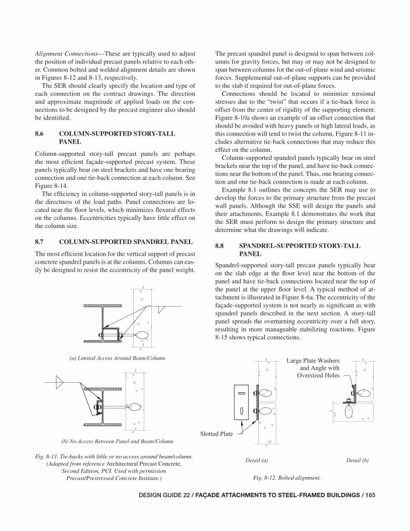
DESIGN GUIDE 22 / FAÇADE ATTACHMENTS TO STEEL-FRAMED BUILDINGS / 165
The precast spandrel panel is designed to span between col-umns for gravity forces, but may or may not be designed to span between columns for the out-of-plane wind and seismic forces. Supplemental out-of-plane supports can be provided to the slab if required for out-of-plane forces.
Connections should be located to minimize torsional stresses due to the “twist” that occurs if a tie-back force is offset from the center of rigidity of the supporting element. Figure 8-10a shows an example of an offset connection that should be avoided with heavy panels or high lateral loads, as this connection will tend to twist the column. Figure 8-11 in-cludes alternative tie-back connections that may reduce this effect on the column.
Column-supported spandrel panels typically bear on steel brackets near the top of the panel, and have tie-back connec-tions near the bottom of the panel. Thus, one bearing connec-tion and one tie-back connection is made at each column.
Example 8.1 outlines the concepts the SER may use to develop the forces to the primary structure from the precast wall panels. Although the SSE will design the panels and their attachments, Example 8.1 demonstrates the work that the SER must perform to design the primary structure and determine what the drawings will indicate.
8.8 SPANDREL-SUPPORTED STORY-TALL PANEL
Spandrel-supported story-tall precast panels typically bear on the slab edge at the fl oor level near the bottom of the panel and have tie-back connections located near the top of the panel at the upper fl oor level. A typical method of at-tachment is illustrated in Figure 8-6a. The eccentricity of the façade-supported system is not nearly as signifi cant as with spandrel panels described in the next section. A story-tall panel spreads the overturning eccentricity over a full story, resulting in more manageable stabilizing reactions. Figure 8-15 shows typical connections.
Alignment Connections—These are typically used to adjust the position of individual precast panels relative to each oth-er. Common bolted and welded alignment details are shown in Figures 8-12 and 8-13, respectively.
The SER should clearly specify the location and type of each connection on the contract drawings. The direction and approximate magnitude of applied loads on the con-nections to be designed by the precast engineer also should be identifi ed.
8.6 COLUMN-SUPPORTED STORY-TALL PANEL
Column-supported story-tall precast panels are perhaps the most effi cient façade-supported precast system. These panels typically bear on steel brackets and have one bearing connection and one tie-back connection at each column. See Figure 8-14.
The effi ciency in column-supported story-tall panels is in the directness of the load paths. Panel connections are lo-cated near the fl oor levels, which minimizes fl exural effects on the columns. Eccentricities typically have little effect on the column size.
8.7 COLUMN-SUPPORTED SPANDREL PANEL
The most effi cient location for the vertical support of precast concrete spandrel panels is at the columns. Columns can eas-ily be designed to resist the eccentricity of the panel weight.
Fig. 8-11. Tie-backs with little or no access around beam/column. (Adapted from reference Architectural Precast Concrete,
Second Edition, PCI. Used with permission Precast/Prestressed Concrete Institute.) Fig. 8-12. Bolted alignment.
157-174_DG22_Ch08.indd 165 7/16/08 4:51:09 PM
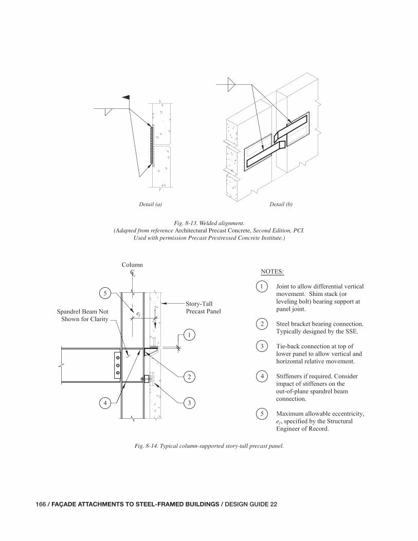
166 / FAÇADE ATTACHMENTS TO STEEL-FRAMED BUILDINGS / DESIGN GUIDE 22
Fig. 8-13. Welded alignment. (Adapted from reference Architectural Precast Concrete, Second Edition, PCI.
Used with permission Precast Prestressed Concrete Institute.)
Fig. 8-14. Typical column-supported story-tall precast panel.
157-174_DG22_Ch08.indd 166 7/16/08 4:51:09 PM

DESIGN GUIDE 22 / FAÇADE ATTACHMENTS TO STEEL-FRAMED BUILDINGS / 167
Fig. 8-15. Typical spandrel-supported story-tall precast panel.
157-174_DG22_Ch08.indd 167 7/16/08 4:51:10 PM

168 / FAÇADE ATTACHMENTS TO STEEL-FRAMED BUILDINGS / DESIGN GUIDE 22
Spandrel-supported spandrel panels typically have two connections located near the top of the panel that bear on the structure at the fl oor level. Tie-back connections are often located near the bottom of the panel height and attach either to the bottom fl ange of the spandrel beam or to a hanger beneath the spandrel beam. Where required, additional tie-back connections are provided for out-of-plane lateral load resistance, and shear plates can be added for in-plane lat-eral load resistance. This is more common in regions of high seismicity.
8.10 POTENTIAL PROBLEMS WITH SUPPORT AND ANCHORAGE OF PRECAST CONCRETE WALL PANELS
The following is a list of potential problems that designers should be aware of and avoid when designing the support and anchorage systems for precast concrete wall panels. There is no particular meaning implied by the order of the list.
• Lack of coordination in the erection sequence for brack-ets, blockouts, and embedment plates. For example, if attachments to the primary structure include connections to steel elements that are embedded in concrete slabs, the construction sequence must be coordinated such that the slabs have been poured and cured to adequate design strength prior to precast erection.
• Cantilevers with insuffi cient stiffness may defl ect or rotate signifi cantly during erection. Stiff cantilevers are benefi cial in reducing the amount of fi nal adjustment required after erection.
Examples 6.5 and 6.6 illustrate the procedures required to design spandrel beams for the effects of eccentric loading due to typical story-tall precast panels.
8.9 SPANDREL-SUPPORTED SPANDREL PANEL
Spandrel precast panels are often utilized in architectural layouts with continuous horizontal bands of windows. While it tends to be more effi cient to support the panels at the col-umns, spandrel beam support is also common. Spandrel-supported spandrel panels are typically subject to signifi cant eccentricities resulting in the added costs of reinforcement or heavier steel sections. For this reason, the designer should minimize the distance between the panel and the support member.
Providing bearing connections directly over the centerline of the spandrel beam minimizes the effect of eccentricity on the primary structure, but is often impractical because of the length of the connection required and the sizable eccen-tricities imparted on the connection to the panel (see Figure 8-16a). It is more common to bear on the slab edge or steel bracket supports such that the panel connection is located as close as possible to the inside face of the precast panel. This is demonstrated in Figure 8-16b. When the bearing connec-tion occurs on a cantilevered slab edge, additional support, such as stiffener plates or angles, is typically provided under the bearing points to limit rotation and defl ection, as shown in Figure 8-16. The eccentricity to the spandrel beam must be considered in the design of the spandrel beam.
Fig. 8-16. Direct vs. eccentric bearing connections at spandrels.
157-174_DG22_Ch08.indd 168 7/16/08 4:51:10 PM
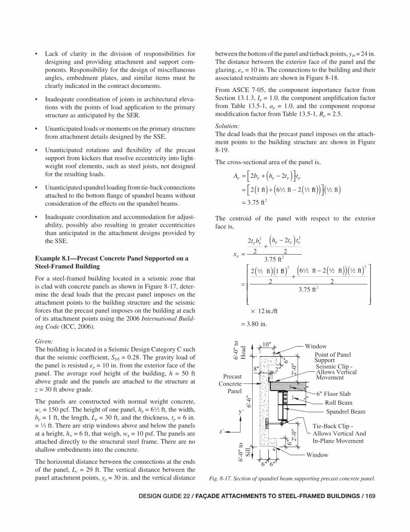
DESIGN GUIDE 22 / FAÇADE ATTACHMENTS TO STEEL-FRAMED BUILDINGS / 169
• Lack of clarity in the division of responsibilities for designing and providing attachment and support com-ponents. Responsibility for the design of miscellaneous angles, embedment plates, and similar items must be clearly indicated in the contract documents.
• Inadequate coordination of joints in architectural eleva-tions with the points of load application to the primary structure as anticipated by the SER.
• Unanticipated loads or moments on the primary structure from attachment details designed by the SSE.
• Unanticipated rotations and fl exibility of the precast support from kickers that resolve eccentricity into light-weight roof elements, such as steel joists, not designed for the resulting loads.
• Unanticipated spandrel loading from tie-back connections attached to the bottom fl ange of spandrel beams without consideration of the effects on the spandrel beams.
• Inadequate coordination and accommodation for adjust-ability, possibly also resulting in greater eccentricities than anticipated in the attachment designs provided by the SSE.
Example 8.1—Precast Concrete Panel Supported on a Steel-Framed Building
For a steel-framed building located in a seismic zone that is clad with concrete panels as shown in Figure 8-17, deter-mine the dead loads that the precast panel imposes on the attachment points to the building structure and the seismic forces that the precast panel imposes on the building at each of its attachment points using the 2006 International Build-ing Code (ICC, 2006).
Given:The building is located in a Seismic Design Category C such that the seismic coeffi cient, SDS = 0.28. The gravity load of the panel is resisted ep = 10 in. from the exterior face of the panel. The average roof height of the building, h = 50 ft above grade and the panels are attached to the structure at z = 30 ft above grade.
The panels are constructed with normal weight concrete, wc = 150 pcf. The height of one panel, hp = 62 ft, the width, bp = 1 ft, the length, Lp = 30 ft, and the thickness, tp = 6 in. = 2 ft. There are strip windows above and below the panels at a height, hw = 6 ft, that weigh, wg = 10 psf. The panels are attached directly to the structural steel frame. There are no shallow embedments into the concrete.
The horizontal distance between the connections at the ends of the panel, Lc = 29 ft. The vertical distance between the panel attachment points, yp = 30 in. and the vertical distance
between the bottom of the panel and tieback points, ytb = 24 in. The distance between the exterior face of the panel and the glazing, ew = 10 in. The connections to the building and their associated restraints are shown in Figure 8-18.
From ASCE 7-05, the component importance factor from Section 13.1.3, Ip = 1.0, the component amplifi cation factor from Table 13.5-1, ap = 1.0, and the component response modifi cation factor from Table 13.5-1, Rp = 2.5.
Solution:The dead loads that the precast panel imposes on the attach-ment points to the building structure are shown in Figure 8-19.
The cross-sectional area of the panel is,
( )A b h t tp p p p p= + −⎡⎣
⎤⎦
= ( ) + −
2 2
2 1 6 2ft ft2 2 fft ft
ft2
( )( )⎡⎣
⎤⎦( )
=
2
3 75.
The centroid of the panel with respect to the exterior face is,
( )x
t b h t t
p
p p p p p
=+
−
=
( )
2
2
2
23 75
2 1
2 2
. ft
ft
2
2 fft ft ft ft
ft2
( )+
− ( )( )( )⎡
⎣
⎢⎢
2 2
2
6 2
23 75
2 2 2
.⎢⎢⎢⎢
⎤
⎦
⎥⎥⎥⎥⎥
×
=
12
3 80
in./ft
in..
Fig. 8-17. Section of spandrel beam supporting precast concrete panel.
157-174_DG22_Ch08.indd 169 7/17/08 11:51:45 AM

170 / FAÇADE ATTACHMENTS TO STEEL-FRAMED BUILDINGS / DESIGN GUIDE 22
The weight of the panel is,
W w A Lpnl c p p=
= ( )( )kip/ft ft ft3 20 150 3 75 30. .
kips= 16 9.
The weight of the windows above bearing on the panel is,
W w h Lwa g w p=
= ( )( )kip/ft 6 ft ft20 010 30.
kips= 1 80.
The weight of the windows below the panel is,
W w h Lwb g w p=
= ( )( )kip/ft 6 ft ft20 010 30.
kips= 1 80.
The total dead load transmitted to the structure is,
W W WD pnl wa= +
==
16 9 1 80
18 7
. .
.
kips + kips
kips
The centroid of the dead load with respect to the point of the gravity support is,
z eW x W e
WD p
pnl p wa w
D
= −+
= −in.kips 3.
1016 9. 880 in. kips in.
kips
( ) + ( )
=
1 80 10
18 7
5
.
.
.660 in.
The vertical dead load to be resisted at points A and C is,
PW
DYD=
=
=
218 7
29 35
.
.
kips
kips
The horizontal (out-of-plane) dead load to be resisted at points A, C, D, and F is,
PW z
yDZ
D D
p
=⎛
⎝⎜
⎞
⎠⎟
=
2
18 7
2
5 60
30
kips in.. .
in.
kips
⎛⎝⎜
⎞⎠⎟
= 1 75.
To determine the seismic forces that the precast panel im-poses on the building at each of its attachment points, the 2006 IBC, Section 1613 refers the reader to ASCE 7-05. See Figure 8-20.
The total effective seismic weight of the panel and windows includes the dead load of the panel and the weight of the portions of the windows above and below that are tributary to the panel,
= +W WW W
p pnlwa wb+
= + +
2 2
16 91 80
2kips
kips.
. 11 80
218 7
.
.
kips
kips=
Fig. 8-18. Elevation of precast panel.Fig. 8-19. Free body diagram of dead load forces
on precast panel.
PDY
PDZ
PDZ
WD
157-174_DG22_Ch08.indd 170 7/16/08 4:51:11 PM

DESIGN GUIDE 22 / FAÇADE ATTACHMENTS TO STEEL-FRAMED BUILDINGS / 171
The centroid of the seismic load with respect to the point of the gravity support is,
2 2+ +
z e
W xW W
e
WE p
pnl pwa wb
w
p
= −
⎛⎝⎜
⎞⎠⎟
= −10
1
in.
66 9 3 80. .kips in.( )18 7
1 80
2
1 80
2
. .kips kips+ +⎛⎝⎜
⎞⎠⎟
110 in.
kips.
18 7 kips.
5 60 in..=
The centroid of the seismic load with respect to the edge corner of the panel is,
2 2y
Wh
Wh
WE
pnl
p
wa
p
p
=
⎛
⎝⎜
⎞
⎠⎟ +
⎛
⎝⎜
⎞
⎠⎟
=16 9 ki. pps
ftkips
ft
k
6
21 80
6
2
18 7
2 2⎛⎝⎜
⎞⎠⎟
+⎛⎝⎜
⎞⎠⎟
.
. iipsin./ft
in.
×=
12
39 0.
From ASCE 7-05 Equation 13.3-1:
= +Fa S W I
R
z
hp
p DS p p
p
⎛⎝⎜
⎞⎠⎟
=( )
0 41
2
0 4 1 0 0
.
. . .228 18 7 1 0
2 51
2 30
50
( )( )( )+
( )⎡
⎣⎢⎢
. .
.
kips ft
ft
⎤⎤
⎦⎥⎥
= kips1 84.
From ASCE 7-05 Equation 13.3-2:
F S I Wp max DS p p=
= ( )( )1 6
1 6 0 28 1 0 18
.
. . . .77
8 38
kips
kips
( )= .
From ASCE 7-05 Equation 13.3-3:
F S I Wp min DS p p=
= ( )( )0 3
0 3 0 28 1 0 18 7
.
. . . . kipps
kips
( )= 1 57.
Equation 13.3-1 controls and this value is used to proceed with the calculations. The seismic force, Fp, must be consid-ered acting both parallel to the plane of the wall and perpen-dicular to the plane of the wall.
Note that these values are for the panel itself, the body of the wall panel connections, and the forces on the base building structure. Based on ASCE 7-05 Equation 13.3-1 the forces on the fasteners of the connecting system may be as much as 313% of the force on the panel, Fp.
The seismic loads parallel to the plane of the panel are il-lustrated in Figure 8-21.
Note that connection B, shown in Figure 8-20, must take all of the in-plane shear from the panel, and connections A and C resist the moment associated with the vertical eccentricity between the seismic force and the supports.
The in-plane shear at point B is,
P FxB p= = 1 84. kips
Fig. 8-20. Plan view of precast panel. Fig. 8-21. Elevation view of panel.
157-174_DG22_Ch08.indd 171 7/16/08 4:51:11 PM
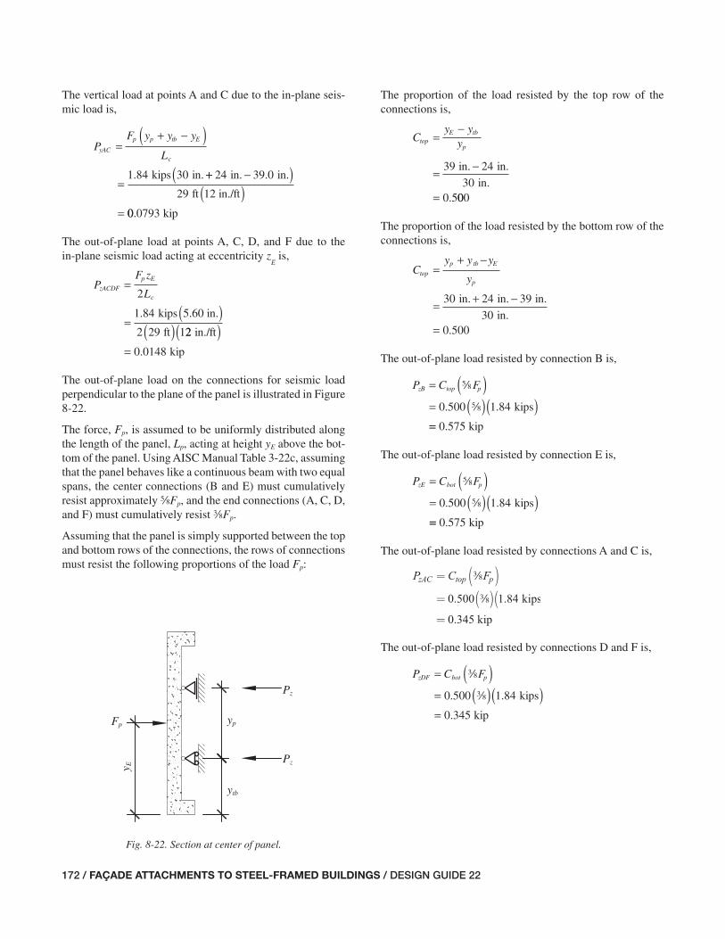
172 / FAÇADE ATTACHMENTS TO STEEL-FRAMED BUILDINGS / DESIGN GUIDE 22
The vertical load at points A and C due to the in-plane seis-mic load is,
( )P
F y y y
LyAC
p p tb E
c
=+ −
=kips in.1 84 30. ++ −( )
( )=
24 39 0
29
in. in.
ft 12 in./ft
.
00 0793. kip
The out-of-plane load at points A, C, D, and F due to the in-plane seismic load acting at eccentricity z
E is,
PF z
LzACDF
p E
c
=
=( )
( )
2
1 84
2 29 1
. kips 5.60 in.
ft 22
0 0148
in./ft
kip
( )= .
The out-of-plane load on the connections for seismic load perpendicular to the plane of the panel is illustrated in Figure 8-22.
The force, Fp, is assumed to be uniformly distributed along the length of the panel, Lp, acting at height yE above the bot-tom of the panel. Using AISC Manual Table 3-22c, assuming that the panel behaves like a continuous beam with two equal spans, the center connections (B and E) must cumulatively resist approximately sFp, and the end connections (A, C, D, and F) must cumulatively resist aFp.
Assuming that the panel is simply supported between the top and bottom rows of the connections, the rows of connections must resist the following proportions of the load Fp:
The proportion of the load resisted by the top row of the connections is,
Cy y
ytopE tb
p=
−
= −
=
39 24
300 5
in. in.
in.. 000
The proportion of the load resisted by the bottom row of the connections is,
Cy y y
ytop
p tb E
p
=+ −
= + −30 24 39
30
in. in. in.
in.= 0 500.
The out-of-plane load resisted by connection B is,
( )P C FzB top p=
= ( )( )s
s kips0 500 1 84. .
== 0 575. kip
The out-of-plane load resisted by connection E is,
( )P C FzE bot p=
= ( )( )s
s kips0 500 1 84. .
== 0 575. kip
The out-of-plane load resisted by connections A and C is,
( )P C FzAC top p=
= ( )(a
a kips
0 500 1 84. .
kip= 0 345.
The out-of-plane load resisted by connections D and F is,
( )P C FzDF bot p=
= ( )( )a
a kips0 500 1 84. .
kip= 0 345.
Fig. 8-22. Section at center of panel.
Pz
Pz
Fp
y E
yp
ytb
157-174_DG22_Ch08.indd 172 7/17/08 11:52:19 AM
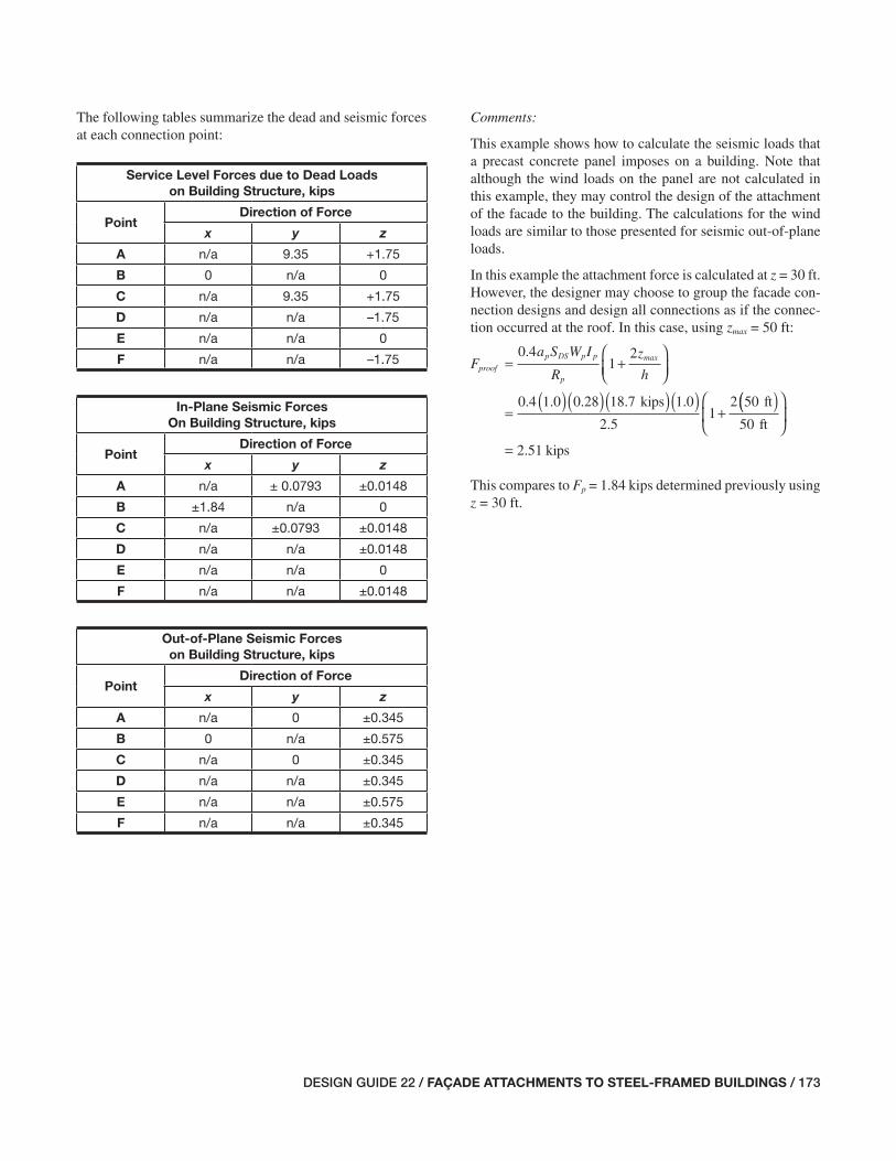
DESIGN GUIDE 22 / FAÇADE ATTACHMENTS TO STEEL-FRAMED BUILDINGS / 173
The following tables summarize the dead and seismic forces at each connection point:
Service Level Forces due to Dead Loads
on Building Structure, kips
PointDirection of Force
x y z
A n/a 9.35 +1.75
B 0 n/a 0
C n/a 9.35 +1.75
D n/a n/a –1.75
E n/a n/a 0
F n/a n/a –1.75
In-Plane Seismic Forces
On Building Structure, kips
PointDirection of Force
x y z
A n/a ± 0.0793 ±0.0148
B ±1.84 n/a 0
C n/a ±0.0793 ±0.0148
D n/a n/a ±0.0148
E n/a n/a 0
F n/a n/a ±0.0148
Out-of-Plane Seismic Forces
on Building Structure, kips
PointDirection of Force
x y z
A n/a 0 ±0.345
B 0 n/a ±0.575
C n/a 0 ±0.345
D n/a n/a ±0.345
E n/a n/a ±0.575
F n/a n/a ±0.345
Comments:
This example shows how to calculate the seismic loads that a precast concrete panel imposes on a building. Note that although the wind loads on the panel are not calculated in this example, they may control the design of the attachment of the facade to the building. The calculations for the wind loads are similar to those presented for seismic out-of-plane loads.
In this example the attachment force is calculated at z = 30 ft. However, the designer may choose to group the facade con-nection designs and design all connections as if the connec-tion occurred at the roof. In this case, using zmax = 50 ft:
proofp
= +Fa S W I
R
z
h
p DS p p max⎛⎝⎜
⎞⎠⎟
0 41
2.
kips ft=
( )( )( )( )+
0 4 1 0 0 28 18 7 1 0
2 51
2 50. . . . .
.
(( )⎛
⎝⎜
⎞
⎠⎟
=
50
2 51
ft
kips.
This compares to Fp = 1.84 kips determined previously using z = 30 ft.
157-174_DG22_Ch08.indd 173 7/16/08 4:51:12 PM

174 / FAÇADE ATTACHMENTS TO STEEL-FRAMED BUILDINGS / DESIGN GUIDE 22
157-174_DG22_Ch08.indd 174 7/16/08 4:51:12 PM
DESIGN GUIDE 22 / FAÇADE ATTACHMENTS TO STEEL-FRAMED BUILDINGS / 175
Chapter 9Aluminum Curtain Walls
9.1 GENERAL DESCRIPTION OF ALUMINUM CURTAIN WALL SYSTEMS
Aluminum curtain wall systems can be either custom or standard type. Standard type curtain walls are usually more economical, but custom-type curtain walls are commonly used because they are tailored to the architect’s design and can be applied to buildings of all shapes and sizes. Whether custom- or standard-type walls are selected, the walls can be assembled in a variety of different systems. Some of the more common systems are: stick-built system, pre-assembled unit system, and unit-and-mullion system. These systems are il-lustrated in Figures 9-1 through 9-3, respectively.
Each type of system has different strategies of installa-tion and varying degrees of adjustment. Stick systems are installed one piece at a time, with the mullions typically in-stalled fi rst. Pre-assembled unit systems are panelized and designed to interlock with adjacent vertical mullions and horizontal rails. Unit-and-mullion systems are a mix between stick systems and pre-assembled unit systems. Mullions are erected fi rst, and pre-assembled units are installed between the mullions. Systems assembled in the plant require fewer connections in the fi eld, which can be cost effective, albeit with reduced adjustability of the system in the fi eld.
Common components of aluminum curtain wall systems are mullions, horizontal rails, spandrel panels, vision glass, interior mullion trim, and anchors. Walls can either be in-fi lled between fl oors or run continuously past the outside face of the fl oor slab edge. In-fi lled systems between fl oor slabs are common for horizontal strip windows and store-front, whereas continuous systems outside of the fl oor slab edge are common for multi-story curtain walls.
Aluminum curtain walls are preferred by designers not only because they are light in weight, but also for ease of in-stallation. Less time is typically required to install aluminum curtain walls than other common façade systems.
The performance of an aluminum curtain wall system is related to the quality of design, fabrication, and installation. Effects from miscellaneous items, such as swing-stage loads and window washers, should be incorporated into the design. Often the most important part of the design is anchorage to the primary building structure. Movement tolerances and re-quired clearances are the most important considerations for the attachment design.
9.2 STRATEGIES FOR SUPPORT OF ALUMINUM CURTAIN WALLS
A strategy for supporting the aluminum curtain wall system starts with the architect’s decision of system type. In-fi lled curtain walls, single-span curtain walls outside of the fl oor slab edge, continuous multi-story curtain walls with lateral support at fl oor slabs, and multi-story curtain walls without fl oor slab support all have different methods of attachment to the primary building structure.
In-fi lled systems span between fl oor slabs and typically bear on the lower fl oor with lateral support at the upper fl oor. Single-span curtain walls have a fi xed connection at one end of the frame and a movable connection at the other end. Con-tinuous multi-story curtain walls with lateral support at fl oor slabs are very common, and are typically supported with a fi xed connection from the spandrel beam at either the pri-mary end or top of the panel, and with movable connections at intermediate fl oor slabs and at the opposite end of the panel. Figure 9-4 illustrates a multi-story support condition. Multi-story curtain walls without fl oor slab support are com-mon at building atriums, and are typically supported with a supplemental vertical or horizontal structural steel girt sys-tem, which usually provides only lateral support.
The most appropriate and effi cient means of anchoring the curtain wall to the primary building structure depends on the type of curtain wall. The following suggestions provide strategies toward successful design:
• Anchors should be located in an easily accessible location. Attachments to the top or side of the slab or spandrel beam are generally easier to install than underside connections.
• Adjustability in all connections should be provided in the vertical direction and both horizontal directions. Two-piece connections with both vertically and horizontally slotted holes are a common method of providing adjustability.
• It is preferable to limit the eccentricity on anchors.
• Since fi reproofi ng is often applied prior to curtain wall installation, blockouts should be provided in the fi re-proofi ng, and patched after the anchors are attached.
• Bolt holes should be made in the shop; not fi eld drilled or fl ame-cut. Erectors often prefer welded connections of steel pieces.
175-184_DG22_Ch09.indd 175 7/16/08 4:51:30 PM

176 / FAÇADE ATTACHMENTS TO STEEL-FRAMED BUILDINGS / DESIGN GUIDE 22
Fig. 9-1. Stick system—schematic of typical version. (Taken from Curtain Wall Design Manual, Editorial Revision: May 2005, AAMA. Used with permission, American Architectural Manufacturers Association.)
Fig. 9-2. Unit system—schematic of typical version. (Taken from Curtain Wall Design Manual, Editorial Revision: May 2005, AAMA. Used with permission, American Architectural Manufacturers Association.)
175-184_DG22_Ch09.indd 176 7/16/08 4:51:30 PM
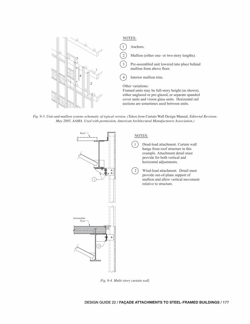
DESIGN GUIDE 22 / FAÇADE ATTACHMENTS TO STEEL-FRAMED BUILDINGS / 177
Fig. 9-3. Unit-and-mullion system–schematic of typical version. (Taken from Curtain Wall Design Manual, Editorial Revision: May 2005, AAMA. Used with permission, American Architectural Manufacturers Association.)
Fig. 9-4. Multi-story curtain wall.
175-184_DG22_Ch09.indd 177 7/16/08 4:51:32 PM
178 / FAÇADE ATTACHMENTS TO STEEL-FRAMED BUILDINGS / DESIGN GUIDE 22
It is important that the installer understand the design in-tent of the various types of curtain wall attachments shown on the contract documents and shop drawings. Misunder-standing can lead to improper installation, and unintended restraint from improperly connected attachments can cause unanticipated forces on the system.
9.3 PARAMETERS AFFECTING THE DESIGN OF ALUMINUM CURTAIN WALL SUPPORTS
Parameters affecting the design of aluminum curtain wall systems include:
• Architectural decisions.
• Movement requirements.
• Field adjustability for tolerances and clearances.
• Durability.
• Fire-safi ng.
9.3.1 Architectural Decisions
Architectural decisions dictate the strategy for supporting the curtain wall system. Decisions that affect the support and attachment of the curtain wall system follow.
Location of the mullions and joints—The location of the ver-tical mullions and horizontal joints of the curtain wall system relative to the primary structural frame drives the designer’s decision for how to support the wall. It is usually economi-cal if the horizontal joints are located within the depth of the spandrel beam so the curtain wall can be attached to the supporting structure without the use of hangers. The closer the anchors are to the spandrel beams, the less distance the supporting attachment steel needs to extend, and this gener-ally means less cost. If the mullion elevation is near the slab edge, it may be possible to fasten it directly to the slab.
Story height—The story height directly impacts the weight and thickness of the system, and also impacts the magnitude of the out-of-plane forces that must be transferred from the mullions to the primary structure.
Curtain wall/support cross section—Current curtain wall de-signs have numerous variations of cross sections with regard to the location of the glass relative to the mullions, rails, and structural support. Multi-story curtain walls in atriums often require horizontal support at intervals along the height of the curtain wall. Structural steel girts are often used to provide this support and can be integrated within, set in front of, or set behind the curtain wall. Another variation is curtain wall systems that span horizontally and require structural steel vertical support. These vertical girts can also be integrated within, set in front of, or set behind the glass.
9.3.2 Movement Requirements
Critical to the performance of an aluminum curtain wall system is the provision for allowance of movement in the joints and connections. Curtain walls are subject to a greater degree of thermal movement than most other types of façade systems, and inadequate detailing of connections to account for movement independent of the primary building struc-ture can result in damage or potentially even failure of the wall system.
Thermal movement stems from both ambient air tempera-ture and solar effects. The range in temperature of metal sur-faces in curtain-wall frames has been known to be as much as 4 or 5 times greater than that of building frames, since temperatures of building frames do not usually vary signifi -cantly. It is therefore essential that thermal movement not be restrained at connections to the primary building structure.
The vertical and lateral stiffness of the supporting struc-ture should satisfy the specifi cations of the curtain wall manufacturer. Common defl ection limitations under lateral loads normal to the plane of the curtain wall are in the range of L/175, where L is the span of the framing member, or a maximum of w in. The allowable defl ection criterion is often L/360 for framing members that are connected to plas-ter or drywall surfaces. There is no industry rule of thumb for vertical stiffness of the supporting framing members, but limiting the support defl ections to less than L/360 is usually suffi cient for curtain wall systems.
9.3.3 Field Adjustability for Tolerances and Clearances
Given the fabrication and erection tolerances of the steel frame, the support details for aluminum curtain walls require fi eld adjustments. The magnitude of the necessary adjust-ments depends on the number of stories and the span lengths, as discussed in Chapter 4. Suggested adjustments include:
• Means to adjust the slab edge in or out relative to the spandrel beam.
• Means to adjust the location of the curtain wall in or out relative to the slab edge.
• Means to adjust the location of the support connections both vertically and horizontally.
The use of erection bolts in slotted holes with fi eld welding is the most common mechanism for achieving the necessary fi eld adjustments.
The clearance dimensions indicated on the drawings should be equal to the sum of the actual net clearance re-quired plus the outward tolerance for closest element of the primary building frame. The American Architectural Manu-facturers Association (AAMA, 1989a) suggests an actual net clearance of not less than 2 in.
175-184_DG22_Ch09.indd 178 7/16/08 4:51:34 PM

DESIGN GUIDE 22 / FAÇADE ATTACHMENTS TO STEEL-FRAMED BUILDINGS / 179
9.3.4 Durability
One of the most common problems with curtain wall sys-tems is water leakage when they are not constructed prop-erly. Improperly sealed joints or sealants that do not provide enough allowance for movement can result in water penetra-tion. It is therefore critical that all connections potentially exposed to moisture be adequately protected. Steel anchors are typically galvanized, or stainless steel is used for protec-tion from moisture.
9.3.5 Fire-Safi ng
Fire-safi ng is required between the slab edge and the back of the curtain wall frame, when aluminum curtain walls are set so they run by the edge of slab. A clearance between the slab edge and system is required to accommodate erection tolerances, and fi re-safi ng must be used to fi ll this gap.
The clearance requirements between the slab edge and façade system, with respect to tolerances, adjustment, and fi re-safi ng discussed in Section 8.3.6, also apply to curtain wall systems.
9.4 DESIGN RESPONSIBILITIES FOR ALUMINUM CURTAIN WALLS
As discussed in Chapter 3, it is important that the design team understands the design responsibilities for the support of aluminum curtain walls. Contracts can defi ne the design responsibilities for each project, and one approach common-ly found on projects with curtain wall façades is discussed in the following text.
Architect—The architect normally has responsibility for the following:
• Early consultation with a curtain wall consultant or design aid.
• Understanding the infl uence of different wall types on cost, anchorage strategies, and installation procedures.
• The performance of the curtain wall with respect to moisture and thermal protection of the building, and to the performance of the system including anchorage to the primary building structure.
• The selection of a single- or multi-story span system (usually in consultation with a curtain wall consultant).
• The mullion layout, including spacing and size [usually in consultation with a curtain wall consultant and based on the advice of the structural engineer of record (SER) for practical limits on sizes of spandrels or girts].
• The selection of joint properties and sealant type.
• The selection of the curtain wall thickness and structural performance requirements (usually in consultation with a curtain wall consultant and the SER).
• The plan location with respect to column and spandrel centerlines.
• The selection of the strategy for supporting the curtain wall system (usually in consultation with the SER).
• The setting of acceptable tolerances for erected and adjusted location of the curtain wall.
Structural Engineer of Record (SER)—The SER normally has responsibility for the following:
• The design of the primary building structure, including the slab, slab edge detail, spandrel beam, roll beams, kickers, etc., to support the forces imposed by the cur-tain wall system with due consideration of stiffness requirements.
• Providing the architect with expected structural design deformations at joints.
• Providing the architect with the vertical and in-plane movements that the curtain wall connections must ac-commodate for structural deformations, for inclusion in the curtain wall specifi cations and/or design.
• Providing fi eld adjustable items at the slab edge accom-modating some, if not all, of the frame erection tolerance (the amount of adjustability should be coordinated with the requirements in the curtain wall specifi cation).
• Indicating on the structural drawings pertinent assump-tions and limitations about the loads from the curtain walls.
• Indicating load support points on the contract drawings.
• Review and approval of shop drawings and fi eld erection drawings for the effect of the aluminum curtain wall and attachments on the primary building structure.
General Contractor—The general contractor normally has responsibility for the following:
• The location of bench marks and offset lines for the curtain wall installer.
• The coordination of the trades involved in installation.
Curtain Wall Manufacturer/SSE—The curtain wall manu-facturer and specialty structural engineer (SSE) normally have responsibility for the following:
175-184_DG22_Ch09.indd 179 7/16/08 4:51:34 PM

180 / FAÇADE ATTACHMENTS TO STEEL-FRAMED BUILDINGS / DESIGN GUIDE 22
• The design of the curtain wall frame and its attachments to the primary building structure.
• To provide guidance to the architect in the selection of the appropriate type of curtain wall system and details for the specifi c building. (This is not typically required of the curtain wall designer, but it is a common occur-rence in this industry, as it benefi ts both the design team and the curtain wall designer as the project develops. The curtain wall manufacturer’s experience with vari-ous structural systems and installation strategies can be advantageous to the project, especially with early input during the design process.)
• The preparation of shop drawings including details of all attachments to the primary building structure, types and locations of anchors clearly noted, and installation pro-cedures and potential diffi culties with fi eld attachment considered and addressed in the shop drawings.
• Clearly marked designation of each piece of the curtain wall system and attachments in accordance with the ap-proved shop drawings, for facilitation of erection.
9.5 CONNECTION TYPES
Proper coordination of the aluminum curtain wall system can prevent costly change orders and problems associated with fi eld installation. In particular, strategies for anchorage to the primary structure should be understood by all parties prior to the curtain wall installation.
Connection types can be divided into two categories: fi xed anchors and movable anchors, which are illustrated in Fig-ures 9-5 and 9-6, respectively. Both types are critical to the stability and performance of the curtain wall system, and the effects of each must be understood and incorporated into the design of the supporting building structure. The SER should clearly specify on the contract drawings any limitations on the location and type of each connection.
Details from example projects are shown in Figures 9-7 and 9-8. The SER must detail the supporting primary struc-ture for the localized bending effects that are imposed from curtain wall anchors. Incorporation of additional stiffener plates, heavier sections, and kickers are common methods of accounting for these forces.
Fig. 9-5. Fixed anchor detail.
175-184_DG22_Ch09.indd 180 7/16/08 4:51:34 PM

DESIGN GUIDE 22 / FAÇADE ATTACHMENTS TO STEEL-FRAMED BUILDINGS / 181
Fig. 9-6. Moveable anchor detail.
Fig. 9-7. Sample structural steel detail at curtain wall attachment.
Fig. 9-8. Sample structural steel detail at curtain wall attachment.
175-184_DG22_Ch09.indd 181 7/16/08 4:51:35 PM

182 / FAÇADE ATTACHMENTS TO STEEL-FRAMED BUILDINGS / DESIGN GUIDE 22
Fixed anchors resist forces in any direction, and are com-monly referred to as pinned connections. Aluminum curtain walls can exhibit a signifi cant amount of thermal movement, and neglecting to account for such movement could result in buckled mullions and overstressed anchors.
Fixed anchors should also be detailed for fi eld adjustment. This can be accomplished with bolted connections with slot-ted holes. Once the anchors are adjusted to their proper posi-tion, the attachments are welded in place. It should be noted that welding is best limited to steel pieces, as welders require more experience with fi eld welding of aluminum to avoid problems. It is usually more practical to use bolted connec-tions for aluminum pieces.
Movable anchors support the wall system from out-of-plane seismic and wind loads, while allowing movement in the vertical and in-plane directions. Common movable an-chor details are illustrated in Figures 9-9 and 9-10. Bolted connections in movable anchors should be tightened such that they allow vertical movement. Washers or slip pads may also be required.
A single-span curtain wall mullion is typically supported by a fi xed anchor at one end of its span and a movable anchor at the other. Common methods of providing both types of these attachments at the interface of two vertical mullions are illustrated in Figures 9-11 and 9-12.
Fig. 9-9. Mullion connection to face of spandrel. (Taken from Curtain Wall Design Manual, Editorial Revision: May 2005, AAMA. Used with permission, American Architectural Manufacturers Association.)
Fig. 9-10. Mullion connection to movable anchor on top of fl oor slab. (Taken from Curtain Wall Design Manual, Editorial Revision: May 2005, AAMA. Used with permission, American Architectural Manufacturers Association.)
175-184_DG22_Ch09.indd 182 7/16/08 4:51:35 PM
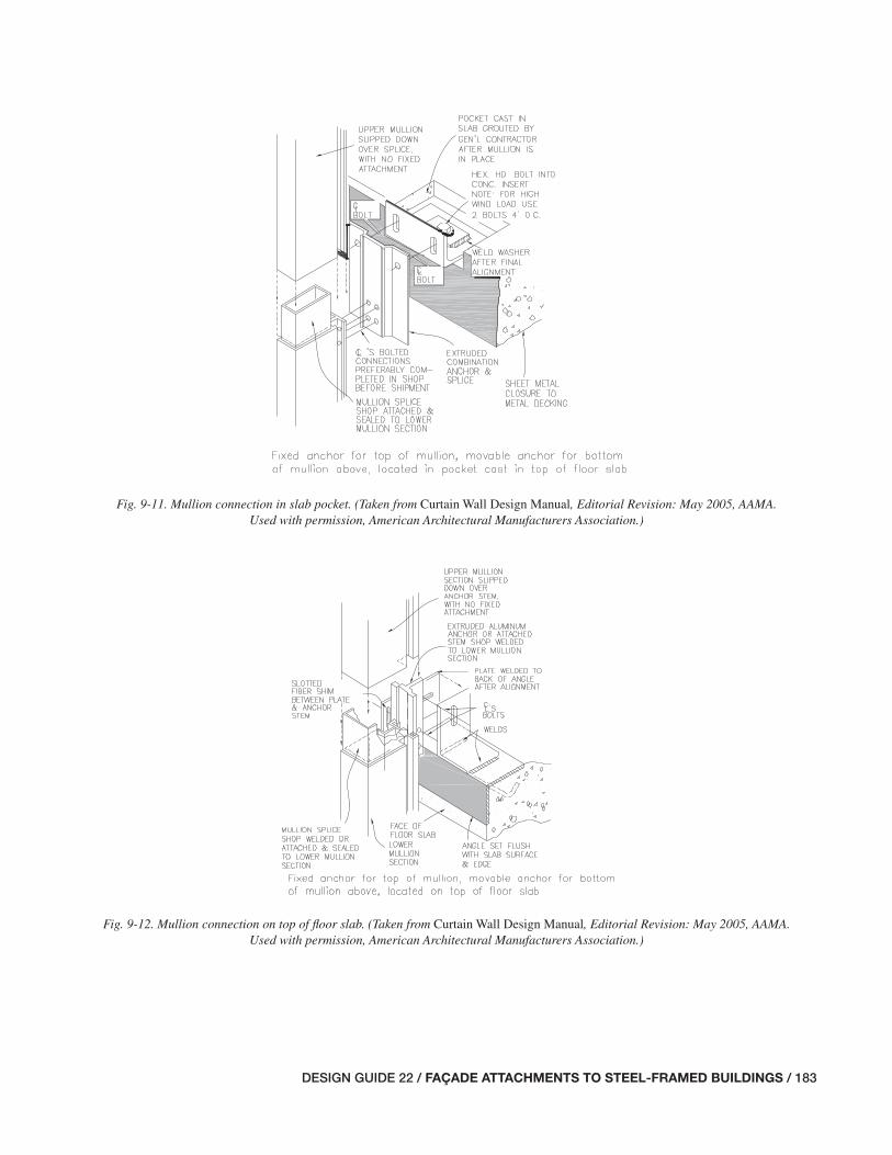
DESIGN GUIDE 22 / FAÇADE ATTACHMENTS TO STEEL-FRAMED BUILDINGS / 183
Fig. 9-11. Mullion connection in slab pocket. (Taken from Curtain Wall Design Manual, Editorial Revision: May 2005, AAMA. Used with permission, American Architectural Manufacturers Association.)
Fig. 9-12. Mullion connection on top of fl oor slab. (Taken from Curtain Wall Design Manual, Editorial Revision: May 2005, AAMA. Used with permission, American Architectural Manufacturers Association.)
175-184_DG22_Ch09.indd 183 7/16/08 4:51:36 PM

184 / FAÇADE ATTACHMENTS TO STEEL-FRAMED BUILDINGS / DESIGN GUIDE 22
There are numerous methods of supporting multi-span curtain walls. Fixed anchors can be located at the top or bot-tom, or even at the midpoint of the mullion. It is common to provide a fi xed anchor at the bottom of the fi rst-story mul-lion and fi xed anchors at the midpoints of two-span mullions above the fi rst fl oor.
One of the most common methods of anchoring curtain wall systems between fl oors is with the use of receptor chan-nels, particularly in horizontal strip window anchorage. Re-ceptors of extruded aluminum can be used at the head of the curtain wall, sill, and at the jambs. They are capable of providing allowance for movement of the primary building structure while being incorporated into the drainage and thermal barrier systems.
Curtain wall attachment pieces can be either steel or alu-minum. Steel anchors are often utilized because of their greater strength, weldability, and more ready availability (aluminum anchors are more typically custom made). Alu-minum anchors can be more versatile in the wall design be-cause of their custom shapes, but they also tend to be more costly. The degree of exposure of the anchors to moisture can also suggest the more suitable material. In exposed con-ditions, aluminum anchors are often selected over steel, be-cause steel anchors typically require a protective coating to prevent corrosion. Consideration must also be given to con-nections between steel and aluminum parts. Without proper separation at meeting surfaces, moisture can lead to a gal-vanic reaction, resulting in corrosion. Plastic pads or Tefl on® washers are commonly used to isolate the materials.
9.6 POTENTIAL PROBLEMS WITH SUPPORT AND ANCHORAGE OF ALUMINUM CURTAIN WALLS
The following is a list of potential problems that designers should be aware of, and avoid, when designing support and anchorage of aluminum curtain walls. There is no particular meaning implied by the order of the list.
• Large gaps between the anchors and the primary building structure can result in excessive bending effects. Welded shims are commonly used to fi ll and reduce the potential for overstressed anchors.
• Lack of coordination of locations of adjustment. If verti-cal and horizontal adjustments are to be made solely in the attachments of the curtain wall system to the primary building structure, slotted holes must be long enough to account for all of the required adjustment. If the curtain wall designer is relying on adjustments being made through the primary building structure rather than the façade attachments, the slotted holes provided may be inadequate in length.
• Lack of coordination of bolted attachments to the pri-mary building structure. Locations of bolt holes for cur-tain wall attachment should be coordinated with the steel fabricator so that holes can be made in the shop.
• Inadequate detailing in mullion splices (which are the responsibility of the SSE) for volume changes and move-ment of the primary building structure.
175-184_DG22_Ch09.indd 184 7/16/08 4:51:37 PM

DESIGN GUIDE 22 / FAÇADE ATTACHMENTS TO STEEL-FRAMED BUILDINGS / 185
Chapter 10Glass-Fiber-Reinforced Concrete (GFRC) Panels and Other Lightweight Systems
10.1 GENERAL DESCRIPTION OF GLASS-FIBER-REINFORCED CONCRETE PANELS AND OTHER LIGHTWEIGHT SYSTEMS
Glass-fi ber-reinforced concrete (GFRC) panels are a versatile and lightweight façade system. Various surface colors and textures are available, making GFRC adaptable to numerous architectural applications. They can be designed with a face mix to achieve an appearance very similar to that of precast concrete panels.
GFRC and other lightweight systems, such as thin brick and stone facings, are benefi cial because they are easy to erect and generally do not require heavy steel structural sup-port in the primary building structure. For these reasons, GFRC and other lightweight systems often result in more economical steel frames.
GFRC panel systems typically weigh between 9 and 25 psf. Actual weights depend on the type of surface fi nish, pan-el shapes and sizes, and back-up frame composition. Typi-cal wall systems are comprised of the panel skin, anchors attaching the skin to the back-up frame, the panel back-up frame, and connectors attaching the panel frame to the pri-mary building structure. Insulation is often located within the panel back-up frame. The panel skin is made up of cement/aggregate slurry and alkali-resistant glass fi bers. Skins are typically sprayed-applied onto forms, as opposed to the less common premixing method. The spraying process involves the simultaneous spraying of glass fi bers and slurry onto a mold, and subsequent compaction of the material. Premixing is the process in which the cement, sand, chopped glass fi ber, and water are mixed together into mortar and then sprayed or cast into a product (PCI, 2001).
Wall systems are primarily either single-skin GFRC pan-els or sandwich panels. Sandwich panels are panels that have a lightweight insulating core with a panel skin attached on each side. This chapter focuses on the more commonly used single-skin panels.
GFRC panels are not load bearing and are not considered part of the lateral load resisting system. The primary build-ing structure must be designed with its own lateral force resisting system and must support the weight and lateral loads from the panel system. Out-of-plane lateral loads and in-plane seismic loads from their own self-weight are trans-ferred from the panel skin to the primary building structure. The GFRC skin and the back-up frame comprise the panel. For a common panel system made with a cold formed metal
back-up frame, the load path from the panel skin is through the skin anchors to the metal studs, from the studs to the upper and lower stud tracks, from the tracks to the connec-tor studs, and from the connector studs to the connector ele-ments that attach to the primary building structure. These system components are illustrated in Figures 10-1 and 10-2.
GFRC panels comprise a barrier wall system for water management. As with all barrier wall systems made from panels, the joints are the key to successful moisture protec-tion performance of the wall system. The joint system should include watertight sealants and should be designed to handle the anticipated movement at the joints.
GFRC and other lightweight panels can either be in-fi lled between fl oors or run continuously past the outside face of the fl oor slab edge. Continuous systems outside of the fl oor slab edge are common for multi-story panels and spandrel panels supporting horizontal strip windows. GFRC panels commonly have been manufactured up to 30 ft in length.
10.2 STRATEGIES FOR SUPPORT OF GFRC PANEL SYSTEMS
Strategies for support of GFRC façades include anchoring the GFRC skin to the back-up frame and supporting the back-up frame from the building structure. Initial cracking problems with GFRC panels have to do with anchoring the GFRC skin to the back-up frame in a manner that restrains the movement of the skin. The main concern designers have when choosing the strategy to support the back-up frame on the structure is ensuring suffi cient allowance for relative movement between the back-up frame and the structural frame.
The attachment of the panel skin to the back-up stud frame is commonly accomplished in one of two methods. In both methods, all anchors transfer out-of-plane lateral loads to the back-up frame. The most common method includes a com-bination of fl ex anchors and seismic and gravity anchors. Figure 10-3 illustrates this strategy for GFRC panel system design. In this strategy, seismic anchors transfer in-plane loads to the back-up frame, gravity anchors support the skin weight, and fl ex anchors provide only out-of-plane wind and seismic support while allowing in-plane lateral movement. Gravity connections can be achieved by bonding an anchor to the skin through the use of a bonding pad, and attaching the anchor to the back-up stud frame with a welded connection.
Alternatively for lightweight panel systems, the skin can be attached to the back-up frame with fl ex anchors only. In this
185-194_DG22_Ch10.indd 185 7/16/08 4:51:55 PM

186 / FAÇADE ATTACHMENTS TO STEEL-FRAMED BUILDINGS / DESIGN GUIDE 22
Fig. 10-1. Gravity anchor and panel framing systems. (Taken from Glass Fiber Reinforced Concrete Panels, Fourth Edition, PCI. Used with permission, Precast/Prestressed Concrete Institute.)
Fig. 10-2. Optional methods of stiffening frame for panels without gravity anchors—for small panels only. (Taken from Glass Fiber Reinforced Concrete Panels, Fourth Edition, PCI.
Used with permission, Precast/Prestressed Concrete Institute.)
185-194_DG22_Ch10.indd 186 7/16/08 4:51:55 PM
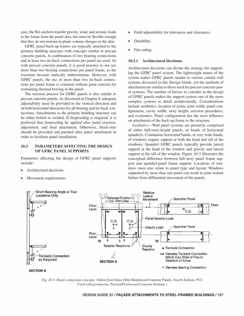
DESIGN GUIDE 22 / FAÇADE ATTACHMENTS TO STEEL-FRAMED BUILDINGS / 187
case, the fl ex anchors transfer gravity, wind, and seismic loads to the frame from the panel skin, but must be fl exible enough that they do not restrain in-plane volume changes in the skin.
GFRC panel back-up frames are typically attached to the primary building structure with concepts similar to precast concrete panels. A combination of two bearing connections and at least two tie-back connections per panel are used. As with precast concrete panels, it is good practice to not use more than two bearing connections per panel frame, as the reactions become statically indeterminate. However, with GFRC panels, the use of more than two tie-back connec-tions per panel frame is common without great concern for restraining thermal bowing in the panel.
The erection process for GFRC panels is also similar to precast concrete panels. As discussed in Chapter 8, adequate adjustability must be provided in the vertical direction and in both horizontal directions for all bearing and tie-back con-nections. Attachments to the primary building structure can be either bolted or welded. If fi reproofi ng is required, it is preferred that fi reproofi ng be applied after panel erection, adjustment, and fi nal attachment. Otherwise, block-outs should be provided and patched after panel attachment in order to facilitate panel installation.
10.3 PARAMETERS AFFECTING THE DESIGN OF GFRC PANEL SUPPORTS
Parameters affecting the design of GFRC panel supports include:
• Architectural decisions.
• Movement requirements.
• Field adjustability for tolerances and clearances.
• Durability.
• Fire-safi ng.
10.3.1 Architectural Decisions
Architectural decisions can dictate the strategy for support-ing the GFRC panel system. The lightweight nature of the system makes GFRC panels similar to various curtain wall systems discussed in this Design Guide, yet the methods of attachment are similar to those used for precast concrete pan-el systems. The number of factors to consider in the design of GFRC panels makes the support system one of the more complex systems to detail architecturally. Considerations include aesthetics, location of joints, joint width, panel con-fi guration, cavity width, story height, erection procedures, and economics. Panel confi guration has the most infl uence on attachment of the back-up frame to the structure.
Aesthetics—Wall panel systems are primarily comprised of either full-story-height panels, or bands of horizontal spandrels. Continuous horizontal bands, or very wide bands, of windows require support at both the head and sill of the windows. Spandrel GFRC panels typically provide lateral support at the head of the window and gravity and lateral support at the sill of the window. Figure 10-3 illustrates the conceptual difference between full-story panel frame sup-port and spandrel-panel frame support. Locations of win-dows must also relate to panel type and layout. Windows supported by more than one panel can result in joint sealant failure from differential movement of the panels.
Fig. 10-3. Panel connection concepts. (Taken from Glass Fiber Reinforced Concrete Panels, Fourth Edition, PCI. Used with permission, Precast/Prestressed Concrete Institute.)
185-194_DG22_Ch10.indd 187 7/17/08 3:22:46 PM

188 / FAÇADE ATTACHMENTS TO STEEL-FRAMED BUILDINGS / DESIGN GUIDE 22
Joints and panel confi guration—Joint sizes and locations are directly related to both the support and performance of the GRFC panel system. Good joint design is based on panel size, tolerances, anticipated movement of the primary build-ing structure and the panel system, and joint materials. Panel confi guration must be established both in elevation and in plan, with respect to the slab edge and supporting structure. Panel back-up frames can either be in-fi lled between fl oors or run continuously past the outside face of the fl oor slab edge.
It is usually economical if the horizontal joints are located within the depth of the spandrel beam, so that the GFRC panel frame can be attached to the supporting structure without the use of hangers. The closer the anchors are to the spandrel beams, the less distance the supporting attachment steel needs to extend, and this generally means less cost.
Cavity width—As further discussed in the “Durability” section, common designs include an air space cavity be-tween the panel skin and the insulation to allow air fl ow and prevent the build-up of moisture in the system. The width of the cavity affects the length of the connections between the panel skin and the back-up frame. Fire-safi ng methods are also dependent on the cavity width and plan confi guration of the panels. See Figure 10-4 for common fi re-safi ng details.
Story height—The story height directly impacts the weight and thickness of the system. The story height also impacts the magnitude of the out-of-plane forces that must be transferred from the back-up frame to the primary structure.
Erection procedures—As with precast concrete panels, erection equipment often infl uences GFRC panel size and should be considered in the selection of panel layout.
Economics—Panel sizes and shapes may be selected to minimize handling and erection time. Panels having similar connections increase overall effi ciency. The workers’ famil-iarity with the connections results in increased productivity. Panel layouts that are repetitive in fi nish, shape, and size will often prove more economical.
10.3.2 Movement Requirements
Both the GFRC skin and building frame movements must be accounted for in the design of GFRC panel joints. The design of the skin–to–back-up anchors must account for the skin movements. The back-up–to–structure attachments must account for the building frame movements.
Movement can be an effect of combinations of tempera-ture, shrinkage, creep, moisture, vertical and lateral loads, and defl ection of the building frame members. GFRC panel systems can be more sensitive to excessive restraint than other systems, and sometimes panels crack as a result of ex-cessive restraint.
Undesired restraint can result from such conditions as overtightened bolted connections and/or the attachments of window frames or signs to the panels. Tefl on® or nylon washers are a common method of providing necessary al-lowance for movement at bolted connections.
Fig. 10-4. Fire-safi ng details. (Taken from Glass Fiber Reinforced Concrete Panels, Fourth Edition, PCI. Used with permission, Precast/Prestressed Concrete Institute.)
185-194_DG22_Ch10.indd 188 7/16/08 4:51:56 PM
DESIGN GUIDE 22 / FAÇADE ATTACHMENTS TO STEEL-FRAMED BUILDINGS / 189
GFRC panels are also perhaps affected more signifi cantly by a broader range of movement sources than most other façade systems. Shrinkage in particular can be signifi cant because of the high percentage of cement in GFRC. Because GFRC panels are typically thinner than precast concrete panels, they also tend to experience greater changes in tem-perature and moisture.
The sum of the movement accommodated by the soft joint will be approximately 25 to 50 percent of the soft joint size, depending on sealant materials and sealant bond. Panel joint width should be a minimum of w in.
The skin must be anchored to the back-up frame with enough support stiffness to mitigate cracking of the panel due to support defl ection. Furthermore, the structural frame must have suffi cient stiffness to adequately support the panel back-up frame. Limiting the spandrel beam and associated support defl ections to less than L/240 for out-of-plane lat-eral loads, where L is the span, is usually suffi cient for most GFRC panels. There is no industry standard of practice for allowable vertical movement due to support defl ection as there is with masonry cavity wall systems because there are any number of GFRC panel and back-up frame confi gura-tions, each with its own limitations. The building frame stiff-ness requirements are usually governed by that needed for acceptable panel joint designs.
10.3.3 Field Adjustability for Tolerances and Clearances
GFRC panel systems require fi eld adjustments for fabrication and erection tolerances of the steel frame. The magnitude of the necessary adjustments depends on the number of stories and the span lengths as discussed in Chapter 4. Suggested adjustments include:
• Means to adjust the slab edge closure plate in or out rela-tive to the spandrel beam.
• Means to adjust the location of the GFRC panel frames in or out relative to the slab edge.
• Means to adjust the location of the GFRC panel frames up or down relative to the slab edge.
• Means to adjust the location of attachment anchors both vertically and horizontally.
Hardware with slotted holes and erection bolts allow hori-zontal adjustment, and shim plates are often used to provide vertical adjustment. If shims are used, they must be placed underneath the panel back-up frames, never underneath the GFRC skin. Placement under the skin could cause un-anticipated loads on the GFRC skin, resulting in cracking and potential failure. For tie-back connections, it is common for designs to use a long, threaded rod, which allows lateral movement in all directions with little restraint from the fl ex-ibility of the rod in bending.
Tolerances relating to production and erection are dis-cussed in detail in Chapter 4, and tolerances in combination with clearances must be considered. Common clearances and cover dimensions considering panel performance as well as production and erection procedures include the fol-lowing (PCI, 2001):
• Panel skin to back-up frame: 2 in. min.
• GFRC backing to fl ex anchors: 8 in. to a in.
• Bonding pad thickness over top of fl ex anchor: 2 in. min.
• Between back of panel frame and fi reproofi ng on steel member: 12 in. min.
• Between back of panel frame and steel member (if not fi reproofed): 12 in. min.
• Exterior face of panel skin to exterior face of insulation (if used): 3 in. min.
10.3.4 Durability
Current design methods for GFRC panels incorporate an air space between the panel skin and the insulation to mitigate moisture accumulation. Vapor barriers are often used as an additional protective measure. Common practice is to place the vapor barrier on the interior side of the insulation in cold-weather environments, and on the exterior of the insulation in warm-weather environments. Any steel on the exterior side of the vapor barrier should be given protection from moisture build-up, which could lead to corrosion. Common protective methods are galvanizing, cadmium plating, and zinc plating. The stud back-up frame is typically coated with G-60 galvanizing. Hot-dip galvanizing or zinc-rich paint is common for attachment hardware.
10.3.5 Fire-Safi ng
As discussed earlier in this chapter for other systems, fi re-safi ng is sometimes required to fi ll the gap between the fl oor slab edge and the inside face of GFRC skin. Mineral wool batt insulation commonly is used to pack the gap, and a fi re and smoke sealant is applied on the top surface of the insulation.
It is generally cost effective to have an adjustable slab edge detail to accommodate at least some of the frame toler-ances to avoid excessive fi re-safi ng.
10.4 DESIGN RESPONSIBILITIES FOR GFRC PANEL SYSTEMS
As discussed in Chapter 3, it is important that the design team understands the design responsibilities for the support of GFRC panel systems. Contracts can defi ne the design re-sponsibilities for each project, and one approach commonly
185-194_DG22_Ch10.indd 189 7/16/08 4:51:56 PM

190 / FAÇADE ATTACHMENTS TO STEEL-FRAMED BUILDINGS / DESIGN GUIDE 22
found on projects with GFRC panels is discussed in the fol-lowing text.
Architect—The architect normally has responsibility for the following:
• The GFRC panel fi nish, shape and size.
• The performance of the GFRC panel system with respect to moisture and thermal protection of the building.
• The selection of the GFRC panel system type (single- skin or sandwich panels, full-story or spandrel panels).
• Determination of the required fi re resistance rating.
• The location of horizontal soft joints (and thus infl uenc-ing the system of support framing).
• The dimension of the horizontal soft joint and perfor-mance of sealant joints (usually in consultation with the SER to understand practical limits for controlling move-ment from the steel frame and support assembly).
• The GFRC panel plan location with respect to column and spandrel centerlines.
• The setting of acceptable tolerances for erected and ad-justed location of panels.
• The test method to be used for performance specifi ca-tions of the panel system.
Structural Engineer of Record (SER)—The SER normally has responsibility for the following:
• The design of the primary building structure, including the slab, slab edge detail, spandrel beam, roll beams, hangers, kickers, etc., to support the forces imposed by the GFRC panel system with due consideration of stiff-ness requirements.
• Providing fi eld adjustable items at the slab edge to ac-commodate some, if not all, of the frame erection toler-ance (the amount of adjustability should be coordinated with the requirements in the GFRC specifi cation, which is especially important if the panel back-up frame is in-fi lled between fl oor slabs).
• Indicating on the structural drawings pertinent assump-tions and limitations about the loads from the panels.
• Indicating load support points on the contract drawings.
• Providing the architect with the vertical and in-plane movements that the GFRC panel frame connections must accommodate for structural deformations, for inclusion in the GFRC specifi cations and/or design.
• Providing the architect with expected structural design deformations at joints.
• Review and approval of shop drawings and fi eld erection drawings for the effect of the GFRC panels and attach-ments on the primary building structure.
General Contractor—The general contractor normally has responsibility for setting the benchmarks to which the GFRC panel installer refers when aligning his work.
GFRC Panel Manufacturer and SSE—The GFRC panel manufacturer and specialty structural engineer (SSE) nor-mally have responsibility for the following:
• The design of the GFRC skin, attachments of the skin to the back-up frame, the back-up frame itself, and the con-nectors that transfer loads from the GFRC panel frame to the primary building structure.
• To clearly mark each panel to correspond with the desig-nations on the approved shop drawings.
• To provide testing of anchors to establish adequate safety factors.
• For loose connection hardware and devices for lifting and erection.
10.5 CONNECTION TYPES
The back-up frame of the GFRC panel is attached to the primary building structure with bearing and tie-back con-nections similar to those used with precast concrete panels. Refer to Chapter 8 for detailed descriptions of bearing and tie-back connection concepts. The most signifi cant differ-ence between precast concrete panel connections and GFRC panel connections, however, is the demand on the anchors and connectors. GFRC panels are much lighter than precast concrete panels, so attachments can be smaller and less costly.
Bearing connections—These can often be lightweight mate-rial such as structural steel angles or bent plates. Stiffener plates can be provided, if necessary, to prevent rotation of the vertical leg of the angle/bent plate.
Given the relatively light weight of the panels, they can usually bear on the slab edge or be attached to a bent plate anchored to the slab.
Tie-Back Connections—These are typically made with threaded rods, but can be metal straps in lightly loaded conditions.
Figures 10-5 and 10-6 illustrate typical bearing and tie-back connections.
185-194_DG22_Ch10.indd 190 7/16/08 4:51:56 PM
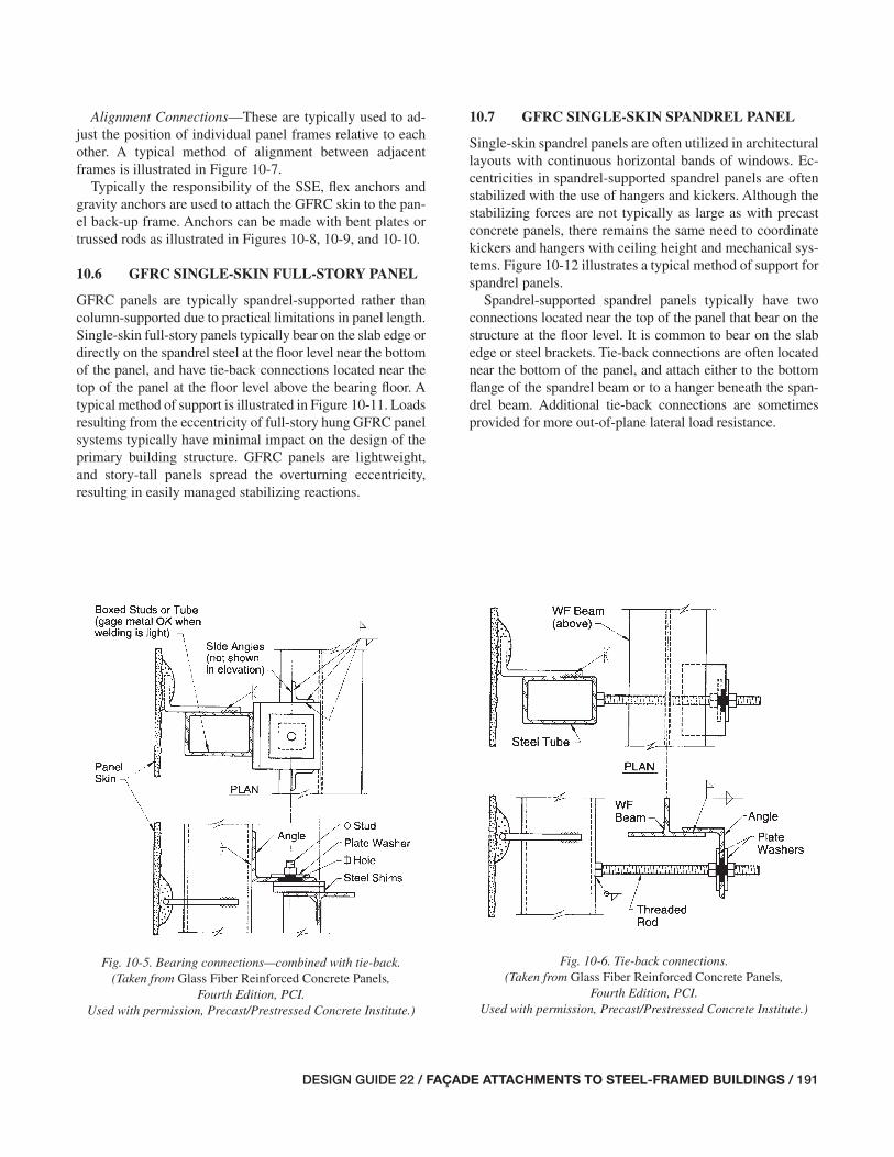
DESIGN GUIDE 22 / FAÇADE ATTACHMENTS TO STEEL-FRAMED BUILDINGS / 191
Alignment Connections—These are typically used to ad-just the position of individual panel frames relative to each other. A typical method of alignment between adjacent frames is illustrated in Figure 10-7.
Typically the responsibility of the SSE, fl ex anchors and gravity anchors are used to attach the GFRC skin to the pan-el back-up frame. Anchors can be made with bent plates or trussed rods as illustrated in Figures 10-8, 10-9, and 10-10.
10.6 GFRC SINGLE-SKIN FULL-STORY PANEL
GFRC panels are typically spandrel-supported rather than column-supported due to practical limitations in panel length. Single-skin full-story panels typically bear on the slab edge or directly on the spandrel steel at the fl oor level near the bottom of the panel, and have tie-back connections located near the top of the panel at the fl oor level above the bearing fl oor. A typical method of support is illustrated in Figure 10-11. Loads resulting from the eccentricity of full-story hung GFRC panel systems typically have minimal impact on the design of the primary building structure. GFRC panels are lightweight, and story-tall panels spread the overturning eccentricity, resulting in easily managed stabilizing reactions.
10.7 GFRC SINGLE-SKIN SPANDREL PANEL
Single-skin spandrel panels are often utilized in architectural layouts with continuous horizontal bands of windows. Ec-centricities in spandrel-supported spandrel panels are often stabilized with the use of hangers and kickers. Although the stabilizing forces are not typically as large as with precast concrete panels, there remains the same need to coordinate kickers and hangers with ceiling height and mechanical sys-tems. Figure 10-12 illustrates a typical method of support for spandrel panels.
Spandrel-supported spandrel panels typically have two connections located near the top of the panel that bear on the structure at the fl oor level. It is common to bear on the slab edge or steel brackets. Tie-back connections are often located near the bottom of the panel, and attach either to the bottom fl ange of the spandrel beam or to a hanger beneath the span-drel beam. Additional tie-back connections are sometimes provided for more out-of-plane lateral load resistance.
Fig. 10-5. Bearing connections—combined with tie-back. (Taken from Glass Fiber Reinforced Concrete Panels,
Fourth Edition, PCI. Used with permission, Precast/Prestressed Concrete Institute.)
Fig. 10-6. Tie-back connections. (Taken from Glass Fiber Reinforced Concrete Panels,
Fourth Edition, PCI. Used with permission, Precast/Prestressed Concrete Institute.)
185-194_DG22_Ch10.indd 191 7/16/08 4:51:56 PM

192 / FAÇADE ATTACHMENTS TO STEEL-FRAMED BUILDINGS / DESIGN GUIDE 22
Fig. 10-7. Alignment connections. (Taken from Glass Fiber Reinforced Concrete Panels, Fourth Edition, PCI.
Used with permission, Precast/Prestressed Concrete Institute.)
Fig. 10-9. Plate gravity anchor. (Taken from Glass Fiber Rein-forced Concrete Panels, Fourth Edition, PCI.
Used with permission, Precast/Prestressed Concrete Institute.)
Fig. 10-8. Trussed rod gravity anchor. (Taken from Glass Fiber Reinforced Concrete Panels, Fourth Edition, PCI.
Used with permission, Precast/Prestressed Concrete Institute.)
Fig. 10-10. Plate and trussed seismic anchors. (Taken from Glass Fiber Reinforced Concrete Panels, Fourth Edition, PCI.
Used with permission, Precast/Prestressed Concrete Institute.)
Skin
BondingPad
185-194_DG22_Ch10.indd 192 7/17/08 3:22:46 PM

DESIGN GUIDE 22 / FAÇADE ATTACHMENTS TO STEEL-FRAMED BUILDINGS / 193
10.8 POTENTIAL PROBLEMS WITH SUPPORT AND ANCHORAGE OF GFRC PANEL SYSTEMS
The following is a list of potential problems that designers should be aware of, and avoid, when designing support and anchorage of masonry cavity walls. There is no particular meaning implied by the order of the list.
• The skins of panels with two material skins should have similar volume change characteristics in order to avoid excessive panel bowing.
• Bowing or warping as a result of cantilevered skins at panel edges.
• Corrosion of support elements and attachments as a re-sult of leaking air and water.
• Insuffi cient coordination with GFRC manufacturer and SSE.
• Over-restraint of panel movement due to thermal and moisture cycles.
• Inadequate allowance for movement of the building frame.
Fig. 10-11. Full-story panel connection.
185-194_DG22_Ch10.indd 193 7/16/08 4:51:57 PM

194 / FAÇADE ATTACHMENTS TO STEEL-FRAMED BUILDINGS / DESIGN GUIDE 22
Fig. 10-12. Strip window panel connection.
185-194_DG22_Ch10.indd 194 7/16/08 4:51:58 PM
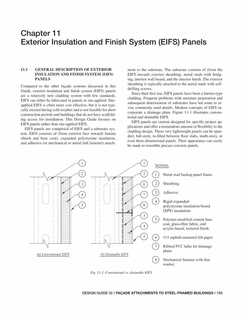
DESIGN GUIDE 22 / FAÇADE ATTACHMENTS TO STEEL-FRAMED BUILDINGS / 195
Chapter 11Exterior Insulation and Finish System (EIFS) Panels
11.1 GENERAL DESCRIPTION OF EXTERIOR INSULATION AND FINISH SYSTEM (EIFS) PANELS
Compared to the other façade systems discussed in this Guide, exterior insulation and fi nish system (EIFS) panels are a relatively new cladding system with few standards. EIFS can either be fabricated in panels or site-applied. Site-applied EIFS is often more cost effective, but it is not typi-cally erected during cold weather and is not feasible for short construction periods and buildings that do not have scaffold-ing access for installation. This Design Guide focuses on EIFS panels rather than site-applied EIFS.
EIFS panels are comprised of EIFS and a substrate sys-tem. EIFS consists of (from exterior face inward) lamina (fi nish and base coat), expanded polystyrene insulation, and adhesive (or mechanical or metal lath fastener) attach-
ment to the substrate. The substrate consists of (from the EIFS inward) exterior sheathing, metal studs with bridg-ing, interior wall board, and the interior fi nish. The exterior sheathing is typically attached to the metal studs with self-drilling screws.
Since their fi rst use, EIFS panels have been a barrier-type cladding. Frequent problems with moisture penetration and subsequent deterioration of substrates have led some to re-vise commonly used details. Modern concepts of EIFS in-corporate a drainage plain. Figure 11-1 illustrates conven-tional and drainable EIFS.
EIFS panels are custom designed for specifi c project ap-plications and offer a tremendous amount of fl exibility to the cladding design. These very lightweight panels can be span-drel, full-story, in-fi lled between fl oor slabs, multi-story, or even three-dimensional panels. Their appearance can easily be made to resemble precast concrete panels.
Rigid expanded polystyrene insulation board(EPS) insulation.
Fig. 11-1. Conventional vs. drainable EIFS.
195-200_DG22_Ch11.indd 195 7/16/08 4:52:16 PM
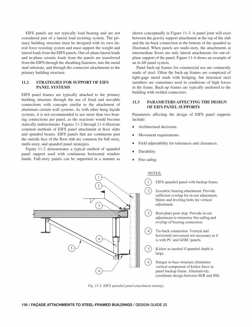
196 / FAÇADE ATTACHMENTS TO STEEL-FRAMED BUILDINGS / DESIGN GUIDE 22
EIFS panels are not typically load bearing and are not considered part of a lateral load resisting system. The pri-mary building structure must be designed with its own lat-eral force resisting system and must support the weight and lateral loads from the EIFS panels. Out-of-plane lateral loadsand in-plane seismic loads from the panels are transferred from the EIFS through the sheathing fasteners, into the metal stud substrate, and through the connector attachments to the primary building structure.
11.2 STRATEGIES FOR SUPPORT OF EIFS PANEL SYSTEMS
EIFS panel frames are typically attached to the primary building structure through the use of fi xed and movable connections with concepts similar to the attachment of aluminum curtain wall systems. As with other hung façade systems, it is not recommended to use more than two bear-ing connections per panel, as the reactions would become statically indeterminate. Figures 11-2 through 11-4 illustrate common methods of EIFS panel attachment at fl oor slabs and spandrel beams. EIFS panels that are continuous past the outside face of the fl oor slab are common for full-story, multi-story, and spandrel panel strategies.
Figure 11-2 demonstrates a typical method of spandrel panel support used with continuous horizontal window bands. Full-story panels can be supported in a manner as
shown conceptually in Figure 11-3. A panel joint will exist between the gravity support attachment at the top of the slab and the tie-back connection at the bottom of the spandrel as illustrated. When panels are multi-story, the attachments at intermediate fl oors are only lateral attachments for out-of-plane support of the panel. Figure 11-4 shows an example of an in-fi ll panel system.
Panel back-up frames for commercial use are commonly made of steel. Often the back-up frames are comprised of light-gage metal studs with bridging, but structural steel members are sometimes used in conditions of high forces in the frame. Back-up frames are typically anchored to the building with welded connectors.
11.3 PARAMETERS AFFECTING THE DESIGN OF EIFS PANEL SUPPORTS
Parameters affecting the design of EIFS panel supportsinclude:
• Architectural decisions.
• Movement requirements.
• Field adjustability for tolerances and clearances.
• Durability.
• Fire-safi ng.
Fig. 11-2. EIFS spandrel panel attachment strategy.
195-200_DG22_Ch11.indd 196 7/16/08 4:52:17 PM

DESIGN GUIDE 22 / FAÇADE ATTACHMENTS TO STEEL-FRAMED BUILDINGS / 197
Fig. 11-3. EIFS full-story panel attachment strategy.
Fig. 11-4. EIFS full-story panel “in-fi ll” strategy.
195-200_DG22_Ch11.indd 197 7/16/08 4:52:18 PM
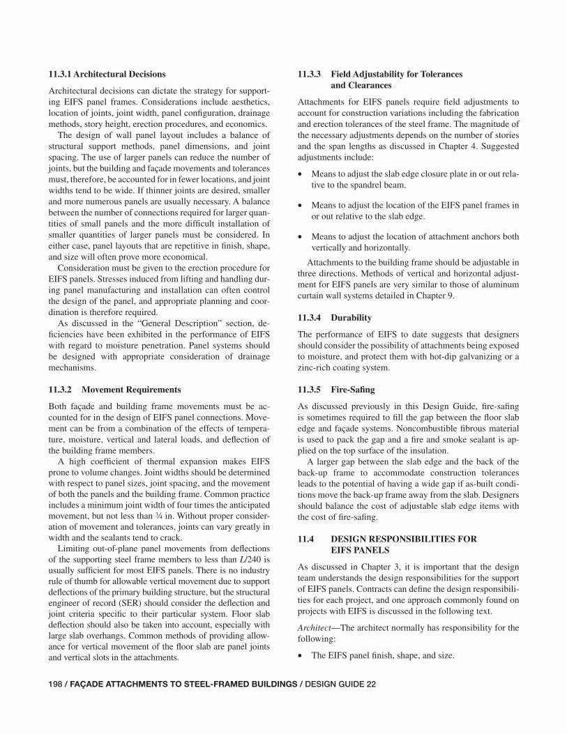
198 / FAÇADE ATTACHMENTS TO STEEL-FRAMED BUILDINGS / DESIGN GUIDE 22
11.3.1 Architectural Decisions
Architectural decisions can dictate the strategy for support-ing EIFS panel frames. Considerations include aesthetics, location of joints, joint width, panel confi guration, drainage methods, story height, erection procedures, and economics.
The design of wall panel layout includes a balance of structural support methods, panel dimensions, and joint spacing. The use of larger panels can reduce the number of joints, but the building and façade movements and tolerances must, therefore, be accounted for in fewer locations, and joint widths tend to be wide. If thinner joints are desired, smaller and more numerous panels are usually necessary. A balance between the number of connections required for larger quan-tities of small panels and the more diffi cult installation of smaller quantities of larger panels must be considered. In either case, panel layouts that are repetitive in fi nish, shape, and size will often prove more economical.
Consideration must be given to the erection procedure for EIFS panels. Stresses induced from lifting and handling dur-ing panel manufacturing and installation can often control the design of the panel, and appropriate planning and coor-dination is therefore required.
As discussed in the “General Description” section, de-fi ciencies have been exhibited in the performance of EIFS with regard to moisture penetration. Panel systems should be designed with appropriate consideration of drainage mechanisms.
11.3.2 Movement Requirements
Both façade and building frame movements must be ac-counted for in the design of EIFS panel connections. Move-ment can be from a combination of the effects of tempera-ture, moisture, vertical and lateral loads, and defl ection of the building frame members.
A high coeffi cient of thermal expansion makes EIFS prone to volume changes. Joint widths should be determined with respect to panel sizes, joint spacing, and the movement of both the panels and the building frame. Common practice includes a minimum joint width of four times the anticipated movement, but not less than w in. Without proper consider-ation of movement and tolerances, joints can vary greatly in width and the sealants tend to crack.
Limiting out-of-plane panel movements from defl ections of the supporting steel frame members to less than L/240 is usually suffi cient for most EIFS panels. There is no industry rule of thumb for allowable vertical movement due to support defl ections of the primary building structure, but the structural engineer of record (SER) should consider the defl ection and joint criteria specifi c to their particular system. Floor slab defl ection should also be taken into account, especially with large slab overhangs. Common methods of providing allow-ance for vertical movement of the fl oor slab are panel joints and vertical slots in the attachments.
11.3.3 Field Adjustability for Tolerances and Clearances
Attachments for EIFS panels require fi eld adjustments to account for construction variations including the fabrication and erection tolerances of the steel frame. The magnitude of the necessary adjustments depends on the number of stories and the span lengths as discussed in Chapter 4. Suggested adjustments include:
• Means to adjust the slab edge closure plate in or out rela-tive to the spandrel beam.
• Means to adjust the location of the EIFS panel frames in or out relative to the slab edge.
• Means to adjust the location of attachment anchors both vertically and horizontally.
Attachments to the building frame should be adjustable in three directions. Methods of vertical and horizontal adjust-ment for EIFS panels are very similar to those of aluminum curtain wall systems detailed in Chapter 9.
11.3.4 Durability
The performance of EIFS to date suggests that designers should consider the possibility of attachments being exposed to moisture, and protect them with hot-dip galvanizing or a zinc-rich coating system.
11.3.5 Fire-Safi ng
As discussed previously in this Design Guide, fi re-safi ng is sometimes required to fi ll the gap between the fl oor slab edge and façade systems. Noncombustible fi brous material is used to pack the gap and a fi re and smoke sealant is ap-plied on the top surface of the insulation.
A larger gap between the slab edge and the back of the back-up frame to accommodate construction tolerances leads to the potential of having a wide gap if as-built condi-tions move the back-up frame away from the slab. Designers should balance the cost of adjustable slab edge items with the cost of fi re-safi ng.
11.4 DESIGN RESPONSIBILITIES FOR EIFS PANELS
As discussed in Chapter 3, it is important that the design team understands the design responsibilities for the support of EIFS panels. Contracts can defi ne the design responsibili-ties for each project, and one approach commonly found on projects with EIFS is discussed in the following text.
Architect—The architect normally has responsibility for the following:
• The EIFS panel fi nish, shape, and size.
195-200_DG22_Ch11.indd 198 7/16/08 4:52:19 PM

DESIGN GUIDE 22 / FAÇADE ATTACHMENTS TO STEEL-FRAMED BUILDINGS / 199
• The performance of the EIFS panel system with respect to moisture and thermal protection of the building.
• The selection of the EIFS type (panels or site-applied).
• The location of horizontal soft joints (thus infl uencing the system of support framing).
• The dimension of the horizontal soft joints and perfor-mance of sealant joints (in consultation with the SER to understand practical limits for controlling movement from the steel frame and support assembly).
• The EIFS panel plan location with respect to column and spandrel center lines.
• The acceptable tolerances for erected and adjusted loca-tion of EIFS panels.
• The test method for performance specifi cations of the panel system.
Structural Engineer of Record (SER)—The SER normally has responsibility for the following:
• The design of the primary building structure, including the slab, slab edge detail, spandrel beam, roll beams, kickers, hangers, etc., for the forces imposed by the EIFS panel system with due consideration to stiffness requirements.
• Providing fi eld adjustable items at the slab edge accom-modating some, if not all, of the frame erection tolerance. (The amount of adjustability should be coordinated with the requirements in the EIFS specifi cation, which is es-pecially important if the panel back-up frame is in-fi lled between fl oor slabs.)
• Indicating on the structural drawings pertinent assump-tions and limitations about the loads from the panels.
• Indicating load support points on the contract drawings.
• Providing the architect with the vertical and in-plane movements that the EIFS panel frame connections must accommodate for structural deformations (for inclusion in the EIFS panel specifi cations and/or design).
• Providing the architect with expected structural design deformations at joints.
• Review and approval of shop drawings and fi eld erection drawings for the effect of the EIFS panels and attach-ments on the primary building structure.
General Contractor—The general contractor normally has responsibility for the following:
• Setting the benchmarks from which the EIFS panel in-staller refers when aligning EIFS work.
• EIFS panel erection, in many cases.
EIFS Panel Manufacturer and SSE—The EIFS panel manu-facturer and specialty structural engineer (SSE) normally have responsibility for the following:
• The design of the EIFS components, the substrate, the attachments of the EIFS to the substrate, and the attach-ments that connect the substrate to the primary building structure.
• Producing shop drawings, which typically include but are not limited to the following:
• Dimensions and locations of panels.
• Panel frame type, including metal stud (or structural steel) sizes, fastening methods, and welding locations.
• The EIFS specifi cations, including fi nish color, rigid expanded polystyrene insulation board (EPS) type and thickness, and type of base coat.
• Erection procedure.
• EIFS panel erection, in some cases.
195-200_DG22_Ch11.indd 199 7/16/08 4:52:19 PM

200 / FAÇADE ATTACHMENTS TO STEEL-FRAMED BUILDINGS / DESIGN GUIDE 22
195-200_DG22_Ch11.indd 200 7/16/08 4:52:20 PM

DESIGN GUIDE 22 / FAÇADE ATTACHMENTS TO STEEL-FRAMED BUILDINGS / 201
Chapter 12Thin Stone Veneer Façade Systems
12.1 GENERAL DESCRIPTION OF THIN STONE VENEER FAÇADE SYSTEMS
The advancement of stone cutting systems in Italy in the 1980s led to thin stone veneer façade systems, which became popular in the United States (Benovengo, 1988). Where pre-viously the thickness norm for stone veneer was 4 to 6 in., the new cutting systems made thicknesses of 3 cm common, with even thinner slabs being bonded to back-up materials to make composite stone cladding units. Additionally, the cut-ting systems have the capability to fabricate thin units with very large slab dimensions, and these lighter stone units have enabled a variety of ways to assemble and install the units into a façade system.
Whereas the thicker 4 to 6 in. stone units can be installed as a typical masonry cavity wall as described in Chapter 7, the thin stone veneer installations usually employ one of three systems.
Truss-supported stone panel systems—These systems have evolved signifi cantly since their introduction. The fi rst systems used steel trusses fabricated with relatively light members. These trusses often spanned from column to col-umn, and the outside face was clad with thin stone units to form the spandrel panel. Many of the fi rst installations relied solely on the stone and the sealant at the unit joints to form a barrier wall without the benefi t of a back-up water or air bar-rier system. The truss and stone were usually prefabricated into panels, allowing them to be erected with the effi ciency of precast concrete panels, but with panels that were signifi -cantly lighter and many options in stone color and texture.
Prefabricated panels allow fabrication of the wall system to start in the shop earlier in the construction schedule and arrive at the site in time for faster enclosure of the build-ing. The trend toward prefabrication has led to designers integrating other essential components of the exterior wall system into the panel, including insulation, air and moisture barriers, drainage planes, and fl ashings. The confi guration of the truss must consider how these other wall components will be integrated into the panel, and how the panel-to-panel joints can be sealed.
The supporting frames for the prefabricated panels are not always steel trusses. Rigid steel frames may form the frame-work for story-tall panels, or for column cover-type panels. Panels are also made from cold-formed light-gage steel stud framing. Steel angles, channels, or hollow structural sec-tions may be integrated into the cold-formed stud framing
as necessary to accept stone support clips and to strengthen the panel. Thin steel straps may form diagonals on the face of the studs for added rigidity. Sometimes a thin steel sheet on the outside face of the studs provides rigidity, and serves as the air and vapor barrier. Alternatively, exterior gypsum sheathing can be used in lieu of the steel sheet. Figures 12-1 and 12-2 illustrate typical panel sections.
Rail-supported stone units—Another manner in which thin stone veneers are incorporated into a wall system is by hand setting each stone in the fi eld on a fi eld-installed rail system supported from a back-up wall. The rails, usually steel or aluminum, are located in the cavity of the wall system be-hind the stone and in front of the air and moisture barriers. The rails are kept relatively thin to keep the cavity from be-ing too large. Thus, the rails are usually supported from the back-up wall at 2- to 3-ft intervals. The rails may be oriented vertically, horizontally, or both in a given system.
Each stone unit is individually supported, usually with two gravity clips supporting the bottom of the stone unit and two lateral clips supporting the top. Sometimes the joints be-tween units are left open and the cavity compartmentalized to form a pressurized rain screen system.
Stone units supported in aluminum curtain wall compo-nents—A third way to use thin stone units in a façade wall system is to use aluminum extrusions to form mullions and support rails in a system much like an aluminum curtain wall. The stone units are individually supported similar to the rail system previously described. This system differs in that the aluminum extrusions are sized such that they can span between fl oors for out-of-plane forces. This system also integrates a drainage plane or cavity, air and water barriers, and fl ashings behind the stone.
All three systems described here rely on a system of stone anchors to attach the individual stone units to the supporting panel, rails, or mullions. Anchors are either stainless steel or aluminum. Often the stone units are fabricated with kerfs in selected sides to allow support clips to engage the stone and resist out-of-plane forces. The thinness of the edges makes for tight tolerances with respect to fabrication and installa-tion of the stone support clips. Prefabrication of panels fa-cilitates achieving these tight tolerances. For fi eld-installed stone units, such as with the rail system and some curtain wall systems, the stone attachments to support frames and support frame attachments to primary structure must have ample adjustability.
201-208_DG22_Ch12.indd 201 7/16/08 4:52:37 PM
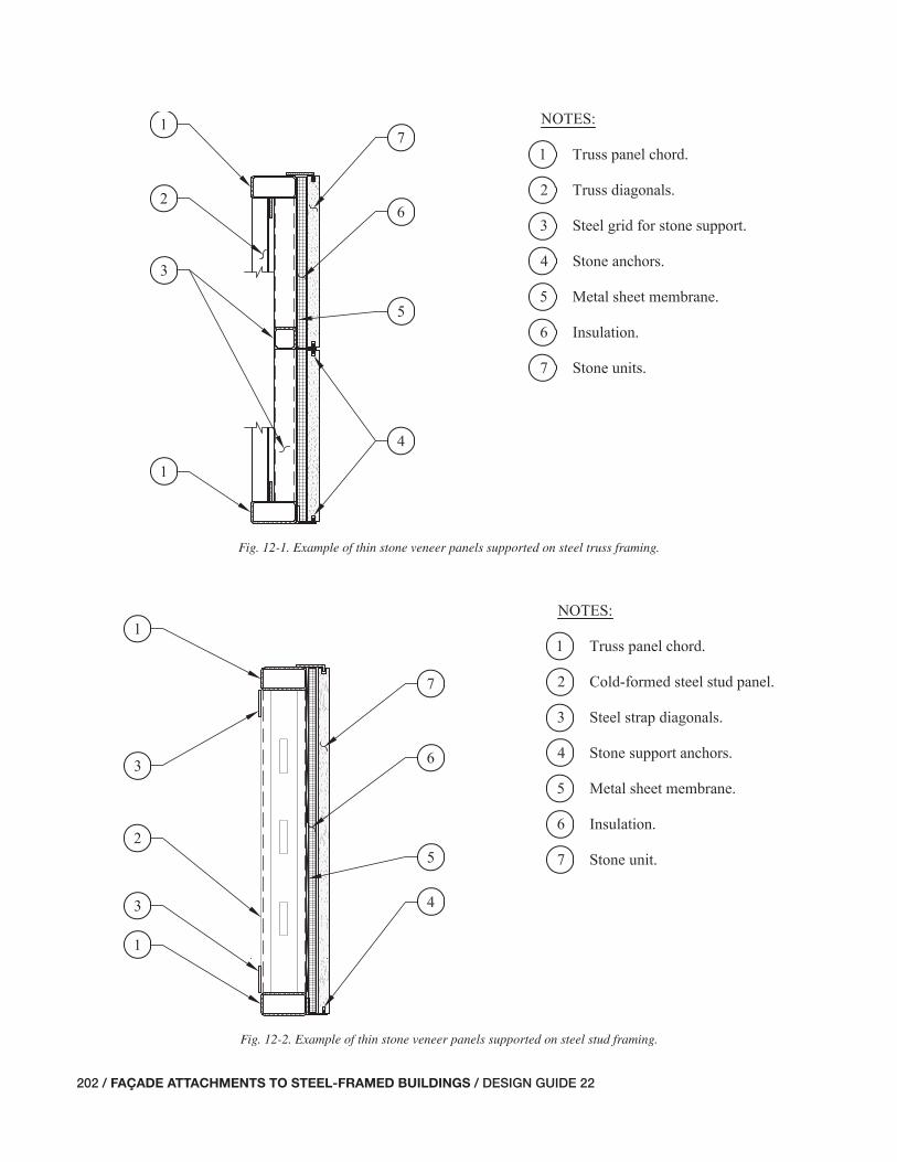
202 / FAÇADE ATTACHMENTS TO STEEL-FRAMED BUILDINGS / DESIGN GUIDE 22
Fig. 12-1. Example of thin stone veneer panels supported on steel truss framing.
Fig. 12-2. Example of thin stone veneer panels supported on steel stud framing.
201-208_DG22_Ch12.indd 202 7/16/08 4:52:37 PM

DESIGN GUIDE 22 / FAÇADE ATTACHMENTS TO STEEL-FRAMED BUILDINGS / 203
12.2 STRATEGIES FOR SUPPORT OF THIN STONE VENEER SYSTEMS
The strategy to support thin stone veneer systems on steel-framed buildings depends on which one of the three system types the project uses. Each uses a strategy similar to other façade systems described in earlier chapters.
Prefabricated panel frames, whether made from steel trusses or cold-formed steel studs, are typically attached to the primary building structure through the use of fi xed and movable connections with concepts similar to the attach-ment of other panel systems such as precast concrete wall panels or GFRC panels. As with other façade systems, it is not recommended to use more than two bearing connections per panel, as the reactions would become statically indeter-minate. Figures 12-3 and 12-4 illustrate common methods of panel attachment.
Figures 12-5 and 12-6 demonstrate a typical method of a truss spandrel panel support. Threaded studs and leveling nuts are often used at the gravity support locations. Bearing is provided by hanging the panel from brackets welded to the primary building columns. Lateral support is provided by “push-pull” connections at the bottom corners and along the truss at intervals, if necessary. Slotted holes and the fl ex-ibility of the push-pull rods prevent unwanted restraint in the plane of the panel. Slotted holes or other provisions should allow horizontal movement in the plane of the panel at one of the bearing points to prevent restraint from thermal strains, especially in long trusses.
Figure 12-7 illustrates a common method of rail system attachment. Rails supporting thin stone units are attached to the primary structure via a back-up wall framing system. For example, a reinforced masonry back-up can be supported and anchored to the primary structure as described for back-up walls in a masonry cavity wall system. Each story of the back-up wall is supported by, and anchored to, the fl oor framing (slab) and laterally braced by the fl oor framing above in such a way as to allow both vertical and horizontal in-plane move-ment between the top of wall and the fl oor framing above. This accommodates the in-plane interstory drift. The continu-ous face of the masonry back-up wall allows for application of an air/water barrier and fastening the rail anchors at any spacing.
Alternatively, steel studs can be used to form the back-up with proper attention to the coordination of the stud spac-ing and rail anchor spacing. Additionally, the fastener design for rail anchors to metal studs must account for the gypsum sheathing that is usually part of a stud wall back-up system. Heavy-gage studs or steel posts may need to be integrated strategically into the back-up wall system.
Thin stone veneer systems that employ aluminum curtain wall type components are attached to the primary frame as described in Chapter 9.
12.3 PARAMETERS AFFECTING THE DESIGN OF THIN STONE VENEER PANEL SUPPORTS
Parameters affecting the design of thin stone veneer panel supports include:
• Architectural decisions.
• Erection procedures.
• Movement requirements.
• Field adjustability for tolerances and clearances.
• Durability.
• Fire-safi ng.
12.3.1 Architectural Decisions
Architectural decisions can dictate the strategy for support-ing thin stone veneer panel frames. Considerations include aesthetics, location of joints, joint width, panel confi gura-tion, stone unit size, drainage methods, and story height.
12.3.2 Erection Procedures
Consideration must be given to the erection procedure as this may dictate which of the support strategies is best for the project. Primary to this is whether a panelized system of erection is desirable and achievable. Panelized systems allow faster erection and, perhaps, better quality of stone work. However, incorporating drainage planes, air/water barriers, and fl ashings—and, as with all prefabricated wall panel systems, achieving continuity of the air/water barriers, and fl ashings—can be diffi cult. Thin stone veneer panels set on rails and stick-built curtain wall assemblies make it easier to achieve continuity of the air/water barriers and fl ashings but require access from the outside, usually from scaffold-ing. The size and location of the project will affect which system is selected for the project. Designers should be aware that past projects have changed strategies during the bidding process.
12.3.3 Movement Requirements
Both façade and building frame movements must be ac-counted for in the design of panel connections. Movement can result from a combination of the effects, including tem-perature, moisture, vertical and lateral loads, and defl ection of the building frame members. Strategies for accommodat-ing relative movements between panels and the primary frame are similar to those recommended for other panel-type façade systems in Chapters 8 and 10.
201-208_DG22_Ch12.indd 203 7/16/08 4:52:38 PM

204 / FAÇADE ATTACHMENTS TO STEEL-FRAMED BUILDINGS / DESIGN GUIDE 22
Fig. 12-3. Thin stone veneer panel support concepts—spandrel panels.
Fig. 12-4. Thin stone veneer panel support concepts—wall panels.
201-208_DG22_Ch12.indd 204 7/16/08 4:52:38 PM

DESIGN GUIDE 22 / FAÇADE ATTACHMENTS TO STEEL-FRAMED BUILDINGS / 205
Fig. 12-5. Example of truss spandrel panel support concept at column.
Fig. 12-6. Example of truss spandrel panel support concept at mid-span.
201-208_DG22_Ch12.indd 205 7/16/08 4:52:38 PM
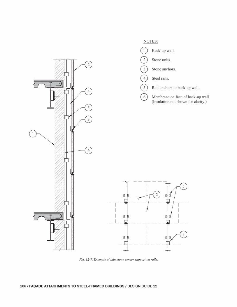
206 / FAÇADE ATTACHMENTS TO STEEL-FRAMED BUILDINGS / DESIGN GUIDE 22
Fig. 12-7. Example of thin stone veneer support on rails.
201-208_DG22_Ch12.indd 206 7/16/08 4:52:39 PM

DESIGN GUIDE 22 / FAÇADE ATTACHMENTS TO STEEL-FRAMED BUILDINGS / 207
For projects with both spandrel panels and column cover-type panels, the joints must accommodate the relative move-ment between panels. The magnitude and the type of joint movement (opening, closing, and translation) will depend on how the panels are attached. For example, if the column cover-type panel rotates with the column, the joints will open and close at the corners of the panel. If the panel is an-chored at just the top or bottom allowing translation relative to the column at the other end, the joints will have horizontal translation.
12.3.4 Field Adjustability for Tolerances and Clearances
Attachments for thin stone veneer panels require fi eld ad-justability to account for construction variations, including the fabrication and erection tolerances of the steel frame. The magnitude of the necessary adjustments depends on the number of stories and the span lengths as discussed in Chap-ter 4. Suggested adjustments include:
• Means to adjust the slab edge closure plate in or out rela-tive to the spandrel beam.
• Means to adjust the location of the panel frames in or out relative to the slab edge.
• Means to adjust the location of attachment anchors both vertically and horizontally.
Attachments to the building frame should be adjustable in three directions. Methods of vertical and horizontal adjust-ment for thin stone veneer panels are very similar to those of GFRC and other lightweight panel systems as detailed in Chapter 10. Projects have been completed successfully with a minimum of 2 in. of horizontal adjustability and 1 in. of vertical adjustability in the attachments (Gulyas, 1988). However, project-specifi c conditions may affect the appro-priateness of these values for other projects.
12.3.5 Durability
The performance of thin stone veneer systems relies heav-ily on the performance of the anchors of the stone units to the support frames, rails, or mullions. The anchors will be exposed to moisture and thus are usually made of stainless steel and sometimes aluminum.
The anchorage of panels to the primary frame may be on the exterior side of the moisture barrier in the system or, if inside it, very near a joint in the barrier as they are often located near the panel joints. Portions of these attachments that will be exposed to moisture and hidden (or diffi cult to expose for inspection) should be corrosion resistant.
12.3.6 Fire-Safi ng
Fire-safi ng must be addressed for thin stone veneer systems made with panels or with curtain wall type fram-ing, both of which typically run by the edge of the slab. As discussed previously in this Guide, fi re-safi ng is sometimes required to fi ll the gap between the fl oor slab edge and fa-çade systems. Noncombustible fi brous material is used to pack the gap and a fi re and smoke sealant is applied on the top surface of the insulation.
A larger gap between the slab edge and the back of the backup frame to accommodate construction tolerances leads to the potential of having a wide gap if as-built conditions move the back-up frame away from the slab. Designers should balance the cost of adjustable slab edge items with the cost of fi re-safi ng.
12.4 DESIGN RESPONSIBILITIES FOR THIN STONE VENEER FAÇADE SYSTEMS
As with other façade systems, it is important that the design team understands the design responsibilities for the support of thin stone veneer faced elements. Contracts can defi ne the design responsibilities for each project, and one approach commonly found on projects with thin stone veneer façades is discussed in the following text.
Architect—The architect normally has responsibility for the following:
• Selection of the stone unit fi nish, shape, and size.
• Selection of the panel, rails, or mullion layout.
• The performance of the wall system with respect to moisture and thermal protection of the building.
• The selection of the dimension of joints and performance of sealant joints (in consultation with the SER to under-stand practical limits for controlling movement from the steel frame and support assembly).
• The plan location of wall system components with respect to column and spandrel centerlines.
• The setting of acceptable tolerances for erected and adjusted location of wall panels.
Structural Engineer of Record (SER)—The SER normally has responsibility for the following:
• The design of the primary building structure, including the slab, slab edge detail, spandrel beam, roll beams, kickers, hangers, etc., for the load imposed by the thin stone veneer wall system with due consideration to stiff-ness requirements.
201-208_DG22_Ch12.indd 207 7/16/08 4:52:39 PM

208 / FAÇADE ATTACHMENTS TO STEEL-FRAMED BUILDINGS / DESIGN GUIDE 22
General Contractor—The general contractor normally has responsibility for the following:
• The locating of benchmarks and offset lines from which the wall installer refers when aligning his work.
• The coordination of the design and construction of the back-up wall and the rail system, if each is provided by a different subcontractor.
Wall System Manufacturer/SSE—For panel systems and curtain-wall-type systems, all aspects of the stone/wall panel assembly should be a sole-source responsibility of a subcon-tractor. For rail-type systems, a sole source responsibility is recommended at least from the face of the back-up wall out. The back-up wall may be included too, or it may be another subcontractor.
One or more SSEs, usually working for the wall contrac-tor, is responsible for the design of the wall structural com-ponents, attachments of the stone units to the frames, and the attachments that connect the frames to the primary building structure. An SSE is responsible for the back-up wall design for rail-type systems.
• Providing the architect with expected structural design deformations at joints.
• Providing the architect with the vertical and in-plane movements that the attachment connections must ac-commodate for structural deformations.
• Providing fi eld adjustable items at the slab edge accom-modating some, if not all, of the frame erection tolerance. (The amount of adjustability should be coordinated with the requirements in the wall assembly specifi cation.)
• Indicating on the structural drawings pertinent assump-tions and limitations about the loads from the wall system.
• Indicating load support points on the contract drawings.
• Review of shop drawings and fi eld erection drawings for the effect of the wall system and attachments on the primary building structure.
201-208_DG22_Ch12.indd 208 7/16/08 4:52:39 PM

DESIGN GUIDE 22 / FAÇADE ATTACHMENTS TO STEEL-FRAMED BUILDINGS / 209
APPENDIX AResults of Finite Element Models to Study the Effect of Slab/Deck Translational Restraint on Spandrel Beams
A.1 GENERAL DESCRIPTION OF MODELS
This appendix presents the results of fi nite element analyses used to establish guidelines for the analysis of torsionally loaded wide-fl ange beams with a top-fl ange diaphragm re-straint. Current design guidelines address the analysis of bare steel beams loaded in torsion but do not address the restraining effect of either a roof deck or composite slab. To provide the designer with useful design guidelines for such situations, the author analyzed 24 fi nite element models. The fi nite element models used thin shell elements to model six wide-fl ange sections of 10-ft and 30-ft spans for the effects of concentrated and uniform torsional loading.
The fi nite element models assumed a pin (three transla-tion degrees of freedom restrained, no rotation or warping restraint) at each edge mesh point along the web, and planer pin restraints (only vertical defl ection permitted, transla-tion in the plane of the slab/deck is restrained, no rotational restraint) along the centerline of the top fl ange. Figure A-1 shows an isometric of a model and schematic supports.
Composite slabs will provide rotational restraint as well as translational restraint. However, the rotational restraint is neglected in this study. This is conservative with respect to estimating rotation of the spandrel.
A.2 ALTERNATIVE METHODS TO APPROXI-MATE TORSIONAL DEFLECTIONS OF TOP-FLANGE-RESTRAINED BEAMS
In addition to presenting the fi nite element results this ap-pendix compares them to two alternative design methods. The fi rst method is called the Modifi ed Flexural Analogy Method. This method uses the fl exural analogy method pre-sented by Salmon and Johnson (1996) for the analysis of steel beams in torsion. However, this method accounts for the fact that the top fl ange cannot translate and thus the beam section rotates about its top fl ange instead of its center.
The Modifi ed Flexural Analogy Method accounts for this by assuming no lateral translation of the top fl ange. The rota-tion is predicted by calculation of the horizontal defl ection of the bottom half of the section and dividing this defl ection by the beam depth.
The second method is called the Modifi ed Design Guide Method. This method uses the analysis method presented in AISC Design Guide No. 9 (Seaburg and Carter, 1997), which considers the beam as a bare steel beam. It is conservatively assumed that the restrained beam rotates the same amount as from AISC Design Guide No. 9, but the rotation is assumed to occur about the top fl ange.
A.3 DISCUSSION OF RESULTS
Tables A-1 through A-4 present beam rotations for 10-ft and 30-ft models subjected to concentrated and uniform torsional loads. These tables also present ratios of the calculated rota-tions for each of the three methods.
The results show that the Modifi ed Flexural Analogy Method provides a more accurate approximation of rotation about the top fl ange at relatively short spans. However, this method becomes increasingly conservative as the beam span increases. The Modifi ed Design Guide Method better pre-dicts rotation about the top fl ange for most beams as beam span increases. The only exception in the studied cases is for the W24×117, which is a deep beam with a relatively large fl ange width.
The ratios of predicted rotation for the methods are simi-lar for both concentrated and uniformly applied loads.
Fig. A-1. Isometric view of fi nite element model.
209-211_DG22_Appendix.indd 209 7/17/08 3:24:44 PM

210 / FAÇADE ATTACHMENTS TO STEEL-FRAMED BUILDINGS / DESIGN GUIDE 22
A.4 CONCLUSIONS AND DESIGN RECOMMENDATIONS
The Modifi ed Flexural Analogy Method requires less com-putation than the Modifi ed Design Guide Method, and more accurately predicts torsional rotations about the top fl ange in short spans. However, the rotations computed with the fl exural analogy can become too conservative for narrow-fl anged beams at long spans. In such cases, the Modifi ed Design Guide Method better predicts the torsional rotations about the top fl ange.
In many cases, the presence of roll beams or kickers will cause the effective torsional span length to be closer to 10 ft than 30 ft. In these cases, the Modifi ed Flexural Analogy Method will not only require less computational effort, but will also provide a more accurate approximation of the beam’s rotation about the top fl ange. For longer spans where this method is too conservative, the Modifi ed Design Guide Method may provide more accurate approximations of beam rotation about the top fl ange.
Table A-1. Top Flange Rotation for 10-ft Span with Distributed Twist
Beam
Rotation (rad.) Ratio
Finite
Element
Model
(FEM)
Modified
Design
Guide
Method
(MDGM)
Modified
Flexural
Analogy
Method
(MFAM)
MDGM/
FEM
MFAM/
FEM
MDGM/
MFAM
W14××30 0.417 0.807 0.477 1.93 1.14 1.69
W14×43 0.178 0.349 0.209 1.97 1.18 1.67
W18×40 0.242 0.468 0.291 1.93 1.20 1.61
W18×60 0.0879 0.175 0.107 1.99 1.22 1.63
W24×62 0.0791 0.158 0.0923 2.00 1.17 1.71
W24×117 0.00865 0.020 0.0101 2.31 1.17 1.97
Table A-2. Top Flange Rotation for 10-ft Span with Concentrated Mid-Span Twist
Beam
Rotation (rad.) Ratio
Finite
Element
Model
(FEM)
Modified
Design
Guide
Method
(MDGM)
Modified
Flexural
Analogy
Method
(MFAM)
MDGM/
FEM
MFAM/
FEM
MDGM/
MFAM
W14××30 0.333 0.648 0.382 1.95 1.15 1.70
W14×43 0.141 0.281 0.168 1.99 1.19 1.68
W18×40 0.193 0.377 0.233 1.96 1.21 1.62
W18×60 0.0699 0.140 0.0858 2.01 1.23 1.64
W24×62 0.0629 0.127 0.0738 2.02 1.17 1.72
W24×117 0.00684 0.016 0.00811 2.34 1.19 1.97
209-211_DG22_Appendix.indd 210 7/16/08 4:52:57 PM

DESIGN GUIDE 22 / FAÇADE ATTACHMENTS TO STEEL-FRAMED BUILDINGS / 211
Table A-3. Top Flange Rotation for 30-ft Span with Distributed Twist
Beam
Rotation (rad.) Ratio
Finite
Element
Model
(FEM)
Modified
Design
Guide
Method
(MDGM)
Modified
Flexural
Analogy
Method
(MFAM)
MDGM/
FEM
MFAM/
FEM
MDGM/
MFAM
W14××30 20.1 25.4 42.4 1.26 2.11 0.599
W14×43 8.37 9.83 17.2 1.17 2.06 0.571
W18×40 10.7 12.9 24.3 1.21 2.27 0.531
W18×60 3.90 4.81 8.72 1.23 2.24 0.551
W24×62 4.11 5.27 7.50 1.28 1.82 0.703
W24×117 0.603 0.961 0.821 1.59 1.36 1.17
Table A-4. Top Flange Rotation for 30-ft Span with Concentrated Mid-Span Twist
Beam
Rotation (rad.) Ratio
Finite
Element
Model
(FEM)
Modified
Design
Guide
Method
(MDGM)
Modified
Flexural
Analogy
Method
(MFAM)
MDGM/
FEM
MFAM/
FEM
MDGM/
MFAM
W14××30 5.43 6.98 10.4 1.29 1.91 0.674
W14×43 2.25 2.71 4.53 1.21 2.01 0.599
W18×40 2.88 3.56 6.29 1.24 2.18 0.566
W18×60 1.05 1.33 2.32 1.27 2.21 0.574
W24×62 1.11 1.44 1.99 1.31 1.80 0.724
W24×117 0.161 0.259 0.219 1.61 1.36 1.18
209-211_DG22_Appendix.indd 211 7/16/08 4:52:57 PM
212 / FAÇADE ATTACHMENTS TO STEEL-FRAMED BUILDINGS / DESIGN GUIDE 22
REFERENCES
American Architectural Manufacturers Association, 1989a, Installation of Aluminum Curtain Walls, CWG-1-89, AAMA, Schaumburg, IL.
American Architectural Manufacturers Association, 1989b, Metal Curtain Wall Manual, MCWM-1-89, AAMA, Schaumburg, IL.
American Architectural Manufacturers Association, 2005, Curtain Wall Design Guide Manual, CW-DG-1-96, AAMA, Schaumburg, IL.
ACI International, 2004, Building Code Requirements for Structural Concrete (ACI 318-05) and Commentary (ACI-318R-05), ACI, Farmington Hills, MI.
ACI International (et al.), 2005, Building Code Require-ments for Masonry Structures (ACI 530-05/ASCE 5-05/TMS 402-5), ACI, Farmington Hills, MI.
American Institute of Steel Construction, 2005a, Code of Standard Practice for Steel Buildings and Bridges (AISC 303-05), AISC, Chicago, IL.
American Institute of Steel Construction, 2005b, Specifi ca-tion for Structural Steel Buildings (ANSI/AISC 360-05), AISC, Chicago, IL.
American Institute of Steel Construction, 2005c, Steel Con-struction Manual, 13th Ed., AISC, Chicago, IL.
American Society of Civil Engineers, 2002, Design Loads on Structures During Construction, SEI/ASCE 37-02, ASCE, Reston, VA.
American Society of Civil Engineers, 2005, Minimum De-sign Loads for Buildings and Other Structures, SEI/ASCE 7-05, ASCE, Reston, VA.
Arnold, C., 2006, “Seismic Safety of the Building Enve-lope”, Whole Building Design Guide, available at http://www.wbdg.org/design/env_seismicsafety.php.
Ballast, D. K., 1994, Handbook of Construction Tolerances, McGraw-Hill, Inc., New York, NY.
Benovengo, E.A. Jr., 1988, “Design Criteria for Thin Stone/Truss Wall Systems,” New Stone Technology, Design, and Construction for Exterior Wall Systems, ASTM STP 996, B. Donaldson, Ed., American Society for Testing and Ma-terials, Philadelphia, PA, pp. 57–65.
Brick Industry Association, 2000, “Volume Changes-Anal-ysis and Effects of Movement,” Technical Notes on Brick Construction, No. 18, Reston, VA.
Brock, L., 2005, Designing the Exterior Wall: An Architec-tural Guide to the Vertical Envelope, John Wiley & Sons, Inc., Hoboken, NJ.
Construction Sciences Research Foundation, 2006, SPEC-TEXT® Master Guide Specifi cations, CSRF, Baltimore, MD.
Griffi s, L.G., 1993, “Serviceability Limit States Under Wind Loads,” Engineering Journal, 1st Qtr., AISC, Vol. 30, No.1, Chicago, IL.
Grimm, C.T. and J.A. Yura, 1989, “Shelf Angles for Mason-ry Veneer”, Journal of Structural Engineering, Vol. 115, No. 3, (March), ASCE, Reston, VA.
Gulyas, S., 1988, “Truss Supported Stone Panel Systems,” New Stone Technology, Design, and Construction for Ex-terior Wall Systems, ASTM STP 996, B. Donaldson, Ed., American Society for Testing and Materials, Philadelphia, PA, pp. 69–86.
International Code Council, 2006, International Building Code, ICC, Country Club Hills, IL.
Janakus, J., R. Huddleston, and B. Wolfe, 2006, Steel Build-ing—Exterior Wall Interfaces, North American Steel Construction Conference (NASCC) Proceedings, AISC, Chicago, IL.
Lin, P.H., 1977, “Simplifi ed Design for Torsional Loading of Rolled Steel Members,” Engineering Journal, AISC, Vol. 14, No. 3, Chicago, IL.
Precast/Prestressed Concrete Institute, 1989, Architectural Precast Concrete, Second Edition, S. Freedman, A.R. Kenney, Eds., PCI, Chicago, IL.
Precast/Prestressed Concrete Institute, 1998, Design and Typical Details of Connections for Precast and Pre-stressed Concrete, A.F. Shaikh, Ed., PCI, Chicago, IL.
Precast/Prestressed Concrete Institute, 2000, Tolerance Manual for Precast and Prestressed Concrete Construc-tion, MNL-135, PCI, Chicago, IL
Precast/Prestressed Concrete Institute, 2001, Recommended Practice for Glass Fiber Reinforced Concrete Panels, Fourth Edition, PCI, Chicago, IL.
Precast/Prestressed Concrete Institute, 2004, PCI Design Handbook, Sixth Edition, L.D. Martin, C.J. Perry, Eds., PCI, Chicago, IL.
212-213_DG22_References.indd 212 7/16/08 4:53:14 PM

DESIGN GUIDE 22 / FAÇADE ATTACHMENTS TO STEEL-FRAMED BUILDINGS / 213
Salmon, C.G. and J.E. Johnson, 1996, Steel Structures De-sign and Behavior: Emphasizing Load and Resistance Factor Design, T.M. Slaughter, Ed., Harper Collins Col-lege Publishers, New York, NY.
Seaburg, P.A. and C.J. Carter, 1997, AISC Design Guide No. 9 Torsional Analysis of Structural Steel Members, AISC, Chicago, IL.
Steel Deck Institute, 2000, SDI Design Manual for Compos-ite Decks, Form Decks, and Roof Decks, Publication No. 30, SDI, Fox River Grove, IL.
Steel Deck Institute, 2004, Diaphragm Design Manual, 3rd Edition, SDI, Fox River Grove, IL.
Thomas, R.G., Jr., 1992, Exterior Insulation and Finish Sys-tem Design Handbook, CMD Associates, Inc., Vashon Is-land, WA.
Tide, R.H. and N.V. Krogstad, 1993, Economical Design of Shelf Angles, J.H. Melander, L.R. Lauersdorf, Eds., ASTM, Philadelphia, PA.
212-213_DG22_References.indd 213 7/16/08 4:53:14 PM