Embed Size (px)
Citation preview
INSTALLATION, OPERATION, MAINTENANCE ANDSYSTEM MANAGEMENT MANUAL
RTQS T E E L
B O I L E R S
2
RANGE
CONFORMITY
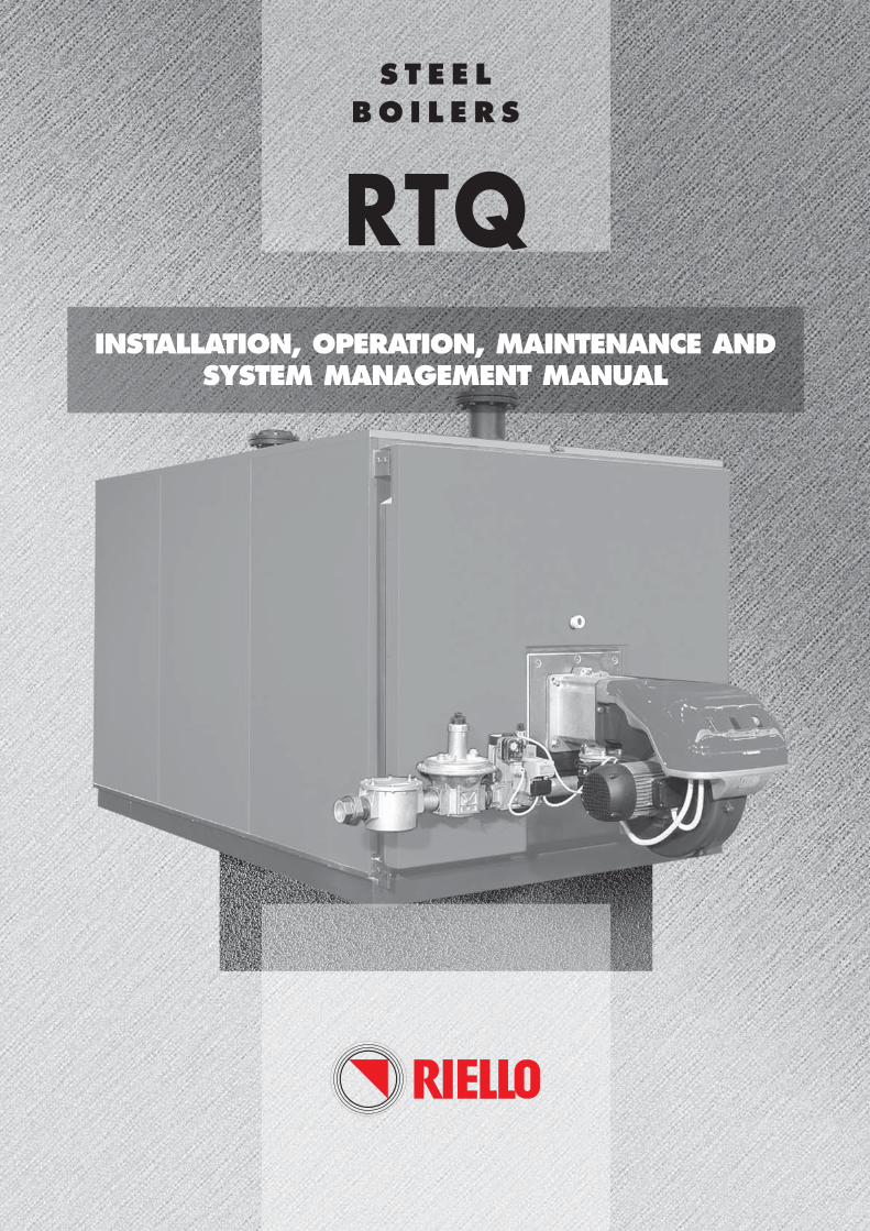
RTQ r boilers conform o the Efficiency Directive 92/42/CEE (..).
When used in conjunction with a CE marked jet burner, they also satisfy the requirements of the
Gas Directive 90/396/EEC and applicable sections of the Electromagnetic Compatibility
Directive 89/336/EEC and Low Voltage Directive 73/23/EEC.
0694
MODEL CODE MODEL CODE
RTQ 91 20012118 RTQ 597 20008946
RTQ 109 20008933 RTQ 715 20008947
RTQ 154 20008935 RTQ 837 20008948
RTQ 203 20008937 RTQ 953 20008950
RTQ 235 20008938 RTQ 1074 20011304
RTQ 297 20008940 RTQ 1308 20011317
RTQ 323 20008941 RTQ 1500 20018769
RTQ 357 20008942 RTQ 1700 20011305
RTQ 418 20008943 RTQ 2000 20016243
RTQ 467 20008944 RTQ 2336 20017225
RTQ 537 20008945
3
WARRANTY
Dear Customer,
Thank you for choosing a RTQ r boiler. You have purchased a modern, high efficiency, quality product that is designed to give dependable and safe service and to provide com-fort in the home for many years to come. Arrange for your boiler to be serviced regularly by an authorised r Technical Assistance Centre. Their personnel are specially trained to keep your boiler efficient and cheap to run. Technical Assistance Centres also stock any original spare parts that might be required.
This instruction manual contains important instructions and precautions that must be observed to ensure the trouble-free installation and efficient functioning of your RTQ r boiler.
Please accept our renewed thanks for your purchase.
Riello S.p.A.
RTQ r boilers are covered by a SPECIAL WARRANTY that comes into force from the date
of validation by your local r Technical Assistance Centre. Consult Yellow Pages to find your
nearest Centre.
We therefore recommend that you contact your local r Technical assistance Centre to arrange for
them to start up your boiler FREE OF CHARGE in compliance with the conditions specified in the
WARRANTY CERTIFICATE supplied with it. Please read the warranty certificate thoroughly.
GENERALGeneral safety information pag. 5Precautions “ 5Product description “ 6Control panels control panels “ 7Recommended burners “ 8Product identification “ 10Technical specifications “ 11
SYSTEM MANAGERStart up pag. 12Temporary shutdown “ 13Preparing for extended periods of disuse “ 14Cleaning “ 15Maintenance “ 15
HEATING ENGINEERUnpacking the product pag. 16Overall dimensions and weights “ 17Handling “ 18Place of installation “ 18Installation in older systems and systemsrequiring modernisation “ 18Water connections “ 19Anti-condensate pump “ 20Combustion gas exhaust “ 21Door hinges “ 21Fitting the casing panels “ 22
TECHNICAL ASSISTANCE SERVICEPreparing for initial start-up pag. 25Initial start-up “ 26Checks during and after initial start-up “ 28Maintenance “ 28- Opening the door “ 28- Adjusting the door “ 28Cleaning the boiler “ 29Troubleshooting “ 30
This manual, Code 20017904 Rev. 3 (12/09) is made up of 32 pages.
CONTENTS4
CONTENTS
The following symbols are used in this manual:
b CAUTION! = Indicates actions that requi-re caution and adequate preparation
a STOP! = Identifies actions that you MUST NOT do
GENERAL 5
GENERAL SAFETY INFORMATION
PRECAUTIONS
b The boiler is delivered in separate crates. Check that it is complete, undamaged and as ordered as soon as you receive it. Report any discrepancies or damage to the dealer who sold it.
b In Italy, Law n° 46 of the 5th March 1990 requires that this r RTQ boiler be installed by a qualified installation company. On completion of the installa-tion, the installer must issue the owner with a decla-ration of conformity confirming that the installation has been completed to the highest standards in compliance with the instructions provided by r in this instruction manual, and that it conforms to all applicable laws and standards.
b The boiler must only be used for the purpose spe-cified by r and for which it is designed. The manufacturer declines all responsibility, contractual or other, for damage to property or injury to per-sons or animals caused by improper installation, adjustment, maintenance or use.
b If you notice any water leaking from the boiler, disconnect it immediately from the mains electricity supply, shut off the water supply, and notify your local r Technical Assistance Centre or a quali-fied heating engineer immediately.
b Periodically check that operating pressure in the water circuit is over 1 bar but below the maximum limit specified for the boiler. If this is not the case, contact r’s Technical Assistance Service or a professionally qualified heating engineer.
b If the boiler is not going to be used for an extended period of time, contact r’s Technical Assistance Service or a qualified heating engineer to have it prepared for shut-down as follows.- Switch the boiler OFF at the control panel and at the
mains power switch. - Close the fuel cock and heating circuit water cock.- Drain the central heating circuit if there is any risk of
freezing.
b The boiler must be serviced at least once a year.
b This instruction manual is an integral part of the boiler. It must be kept safe and must ALWAYS accompany the boiler, even if it is sold to another owner or transferred to another user or to another installation.
If you damage or lose this manual, order a repla-cement immediately from your local r Technical Assistance Centre.
a Do not allow children or infirm persons to operate this r RTQ boiler unsupervised.
a Do not operate any electrical devices or equipment, including switches or domestic appliances, etc., if you can smell fuel or fumes. If you detect any suspi-cious smells:
- Ventilate the room by opening all doors and win-dows.
- Close the fuel shut-off cock.- Report the fault immediately to the r Technical
Assistance Service or a professionally qualified heating engineer.
a Do not touch the boiler while barefoot or wet.
a Never clean or service the boiler without first disconnecting it from the mains electricity supply by turning the main power switch and the control panel switch OFF.
a Do not tamper with or adjust the safety or control devices without prior authorisation and instruc-tions from the boiler’s manufacturer.
a Never pull, disconnect, or twist the electrical cables coming from the boiler even if it is discon-nected from the mains electricity supply.
a Do not obstruct or restrict the vents in the room where the boiler is installed. Adequate ventilation is essential for correct combustion.
a Do not expose the boiler to the elements. Do not install the boiler outdoors. It is not designed to work outdoors and is not fitted with the necessary automatic anti-frost systems to do so.
a Do not switch the boiler off if outdoor temperature drops below ZERO (risk of freezing).
a Do not store containers of flammable substances in the room where the boiler is installed.
a Do not dispose of packaging material into the environment, or leave it within the reach of chil-dren, since it can become a potential hazard. Dispose of packaging material in compliance with applicable legislation.
The operation of any appliance that uses fuel, electrical power and water demands that a number of fundamental safety precautions be respected.
GENERAL6
PRODUCT DESCRIPTION
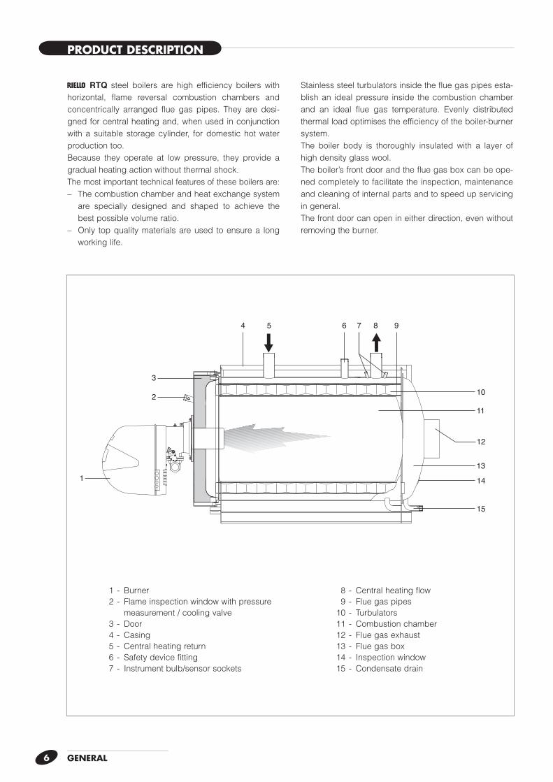
r RTQ steel boilers are high efficiency boilers with horizontal, flame reversal combustion chambers and concentrically arranged flue gas pipes. They are desi-gned for central heating and, when used in conjunction with a suitable storage cylinder, for domestic hot water production too.Because they operate at low pressure, they provide a gradual heating action without thermal shock.The most important technical features of these boilers are:– The combustion chamber and heat exchange system
are specially designed and shaped to achieve the best possible volume ratio.
– Only top quality materials are used to ensure a long working life.
Stainless steel turbulators inside the flue gas pipes esta-blish an ideal pressure inside the combustion chamber and an ideal flue gas temperature. Evenly distributed thermal load optimises the efficiency of the boiler-burner system.The boiler body is thoroughly insulated with a layer of high density glass wool.The boiler’s front door and the flue gas box can be ope-ned completely to facilitate the inspection, maintenance and cleaning of internal parts and to speed up servicing in general.The front door can open in either direction, even without removing the burner.
0
3030
6060 9090
3
2
1
12
4 6 7 85
1314
10
9
11
15
1 - Burner 2 - Flame inspection window with pressure measurement / cooling valve 3 - Door 4 - Casing 5 - Central heating return 6 - Safety device fitting 7 - Instrument bulb/sensor sockets
8 - Central heating flow 9 - Flue gas pipes 10 - Turbulators 11 - Combustion chamber 12 - Flue gas exhaust 13 - Flue gas box 14 - Inspection window 15 - Condensate drain
GENERAL 7
CONTROL PANELS
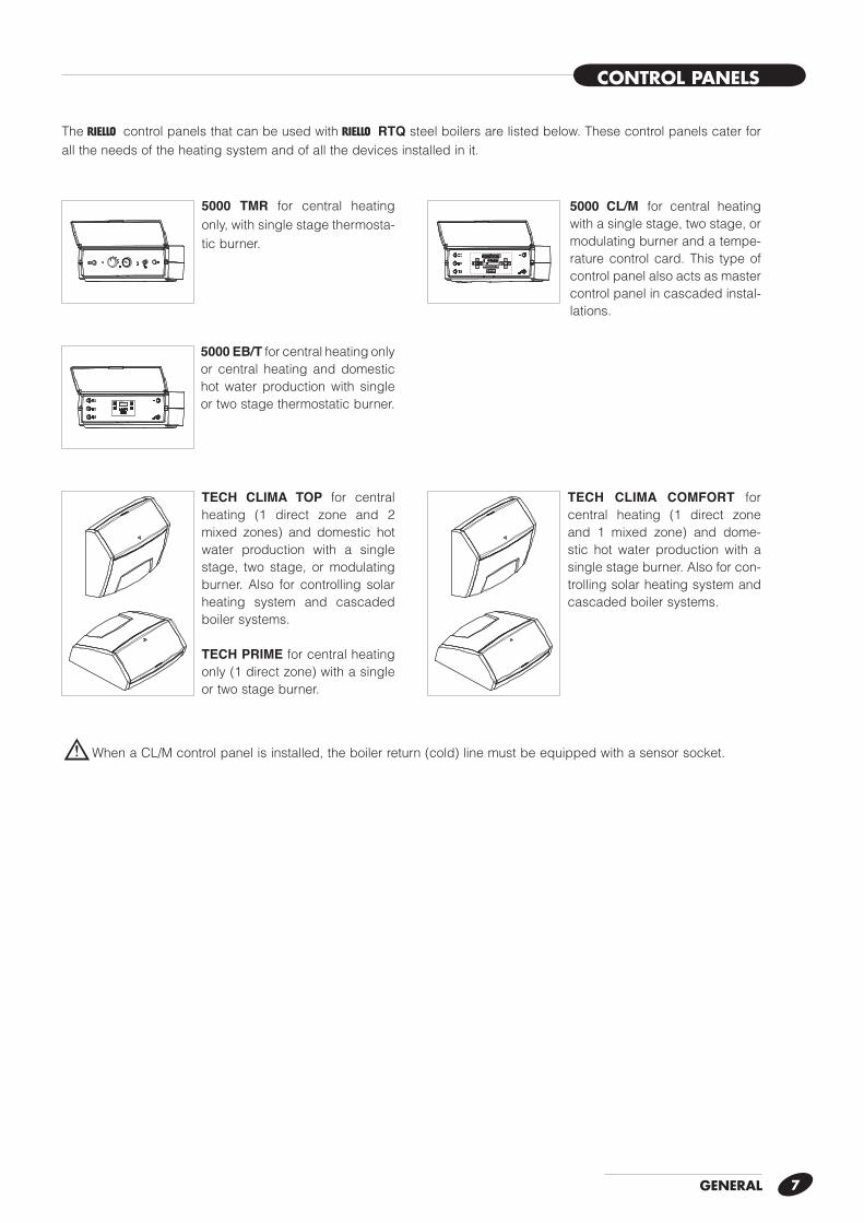
b When a CL/M control panel is installed, the boiler return (cold) line must be equipped with a sensor socket.
The r control panels that can be used with r RTQ steel boilers are listed below. These control panels cater for all the needs of the heating system and of all the devices installed in it.
20
4060
80
100
0 120
5000 TMR for central heating only, with single stage thermosta-tic burner.
5000 EB/T for central heating only or central heating and domestic hot water production with single or two stage thermostatic burner.
5000 CL/M for central heating with a single stage, two stage, or modulating burner and a tempe-rature control card. This type of control panel also acts as master control panel in cascaded instal-lations.
TECH CLIMA TOP for central heating (1 direct zone and 2 mixed zones) and domestic hot water production with a single stage, two stage, or modulating burner. Also for controlling solar heating system and cascaded boiler systems.
TECH PRIME for central heating only (1 direct zone) with a single or two stage burner.
TECH CLIMA COMFORT for central heating (1 direct zone and 1 mixed zone) and dome-stic hot water production with a single stage burner. Also for con-trolling solar heating system and cascaded boiler systems.
8
RECOMMENDED BURNERS
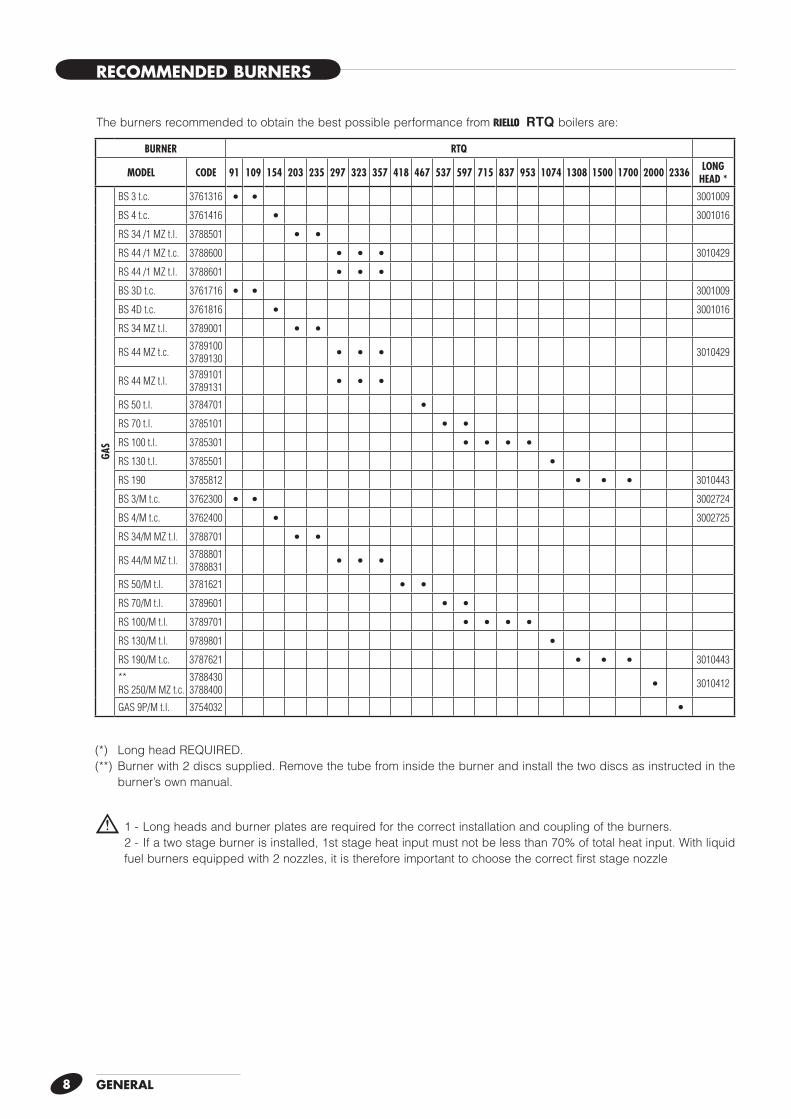
The burners recommended to obtain the best possible performance from r RTQ boilers are:
GENERAL
(*) Long head REQUIRED.(**) Burner with 2 discs supplied. Remove the tube from inside the burner and install the two discs as instructed in the
burner’s own manual.
b 1 - Long heads and burner plates are required for the correct installation and coupling of the burners. 2 - If a two stage burner is installed, 1st stage heat input must not be less than 70% of total heat input. With liquid
fuel burners equipped with 2 nozzles, it is therefore important to choose the correct first stage nozzle
BURNER RTQ
MODEL CODE 91 109 154 203 235 297 323 357 418 467 537 597 715 837 953 1074 1308 1500 1700 2000 2336 LONGHEAD *
GAS
BS 3 t.c. 3761316 • • 3001009
BS 4 t.c. 3761416 • 3001016
RS 34 /1 MZ t.l. 3788501 • •RS 44 /1 MZ t.c. 3788600 • • • 3010429
RS 44 /1 MZ t.l. 3788601 • • •BS 3D t.c. 3761716 • • 3001009
BS 4D t.c. 3761816 • 3001016
RS 34 MZ t.l. 3789001 • •RS 44 MZ t.c. 3789100
3789130 • • • 3010429
RS 44 MZ t.l. 37891013789131 • • •
RS 50 t.l. 3784701 •RS 70 t.l. 3785101 • •RS 100 t.l. 3785301 • • • •RS 130 t.l. 3785501 •RS 190 3785812 • • • 3010443
BS 3/M t.c. 3762300 • • 3002724
BS 4/M t.c. 3762400 • 3002725
RS 34/M MZ t.l. 3788701 • •RS 44/M MZ t.l. 3788801
3788831 • • •RS 50/M t.l. 3781621 • •RS 70/M t.l. 3789601 • •RS 100/M t.l. 3789701 • • • •RS 130/M t.l. 9789801 •RS 190/M t.c. 3787621 • • • 3010443
** RS 250/M MZ t.c.
37884303788400 • 3010412
GAS 9P/M t.l. 3754032 •
9GENERAL
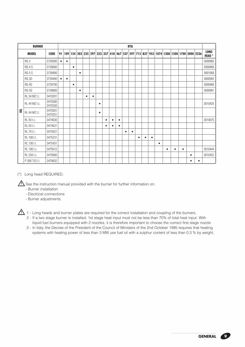
(*) Long head REQUIRED.
b See the instruction manual provided with the burner for further information on:- Burner installation- Electrical connections- Burner adjustments.
b 1 - Long heads and burner plates are required for the correct installation and coupling of the burners. 2 - If a two stage burner is installed, 1st stage heat input must not be less than 70% of total heat input. With liquid fuel burners equipped with 2 nozzles, it is therefore important to choose the correct first stage nozzle 3 - In Italy, the Decree of the President of the Council of Ministers of the 2nd October 1995 requires that heating systems with heating power of less than 3 MW use fuel oil with a sulphur content of less than 0.3 % by weight.
BURNER RTQ
MODEL CODE 91 109 154 203 235 297 323 357 418 467 537 597 715 837 953 1074 1308 1500 1700 2000 2336 LONGHEAD *
OIL
RG 3 3739300 • • 3000965
RG 4 S 3739600 • 3000966
RG 5 S 3739900 • 3001068
RG 3D 3739400 • • 3000965
RG 4D 3739700 • 3000966
RG 5D 3739800 • 3000981
RL 34 MZ t.l. 3470201 • •RL 44 MZ t.c. 3470300
3470330 • 3010425
RL 44 MZ t.l. 34703013470331 •
RL 50 t.c. 3474630 • • • 3010075
RL 50 t.l. 3474631 • • •RL 70 t.l. 3475031 • •RL 100 t.l. 3475231 • • •RL 130 t.l. 3475431 •RL 190 t.c. 3475612 • • • 3010444
RL 250 t.c. 3470000 • 3010422
P 300 T/G t.l. 3478832 • •
GENERAL10
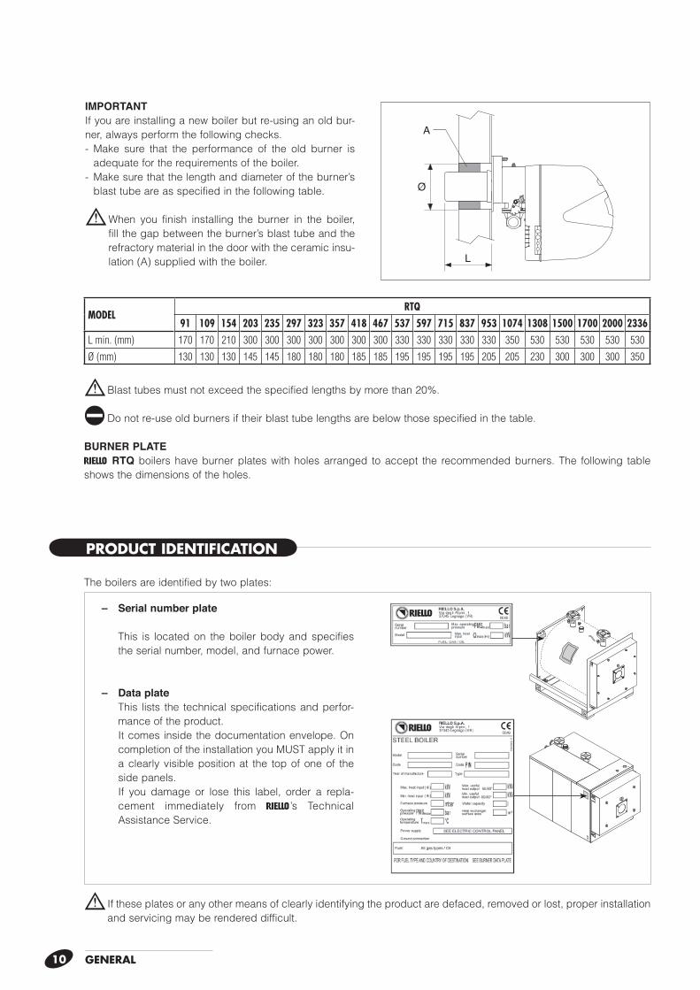
b If these plates or any other means of clearly identifying the product are defaced, removed or lost, proper installation and servicing may be rendered difficult.
– Serial number plate
This is located on the boiler body and specifies the serial number, model, and furnace power.
– Data plate This lists the technical specifications and perfor-
mance of the product. It comes inside the documentation envelope. On
completion of the installation you MUST apply it in a clearly visible position at the top of one of the side panels.
If you damage or lose this label, order a repla-cement immediately from r’s Technical Assistance Service.
The boilers are identified by two plates:
PRODUCT IDENTIFICATION
b Blast tubes must not exceed the specified lengths by more than 20%.
a Do not re-use old burners if their blast tube lengths are below those specified in the table.
BURNER PLATEr RTQ boilers have burner plates with holes arranged to accept the recommended burners. The following table shows the dimensions of the holes.
IMPORTANTIf you are installing a new boiler but re-using an old bur-ner, always perform the following checks.- Make sure that the performance of the old burner is
adequate for the requirements of the boiler.- Make sure that the length and diameter of the burner’s
blast tube are as specified in the following table.
b When you finish installing the burner in the boiler, fill the gap between the burner’s blast tube and the refractory material in the door with the ceramic insu-lation (A) supplied with the boiler.
A
Ø
L
MODELRTQ
91 109 154 203 235 297 323 357 418 467 537 597 715 837 953 1074 1308 1500 1700 2000 2336L min. (mm) 170 170 210 300 300 300 300 300 300 300 330 330 330 330 330 350 530 530 530 530 530
Ø (mm) 130 130 130 145 145 180 180 180 185 185 195 195 195 195 205 205 230 300 300 300 350
GEN
ERAL
11
TECHN
ICAL SPECIFICA
TION
S
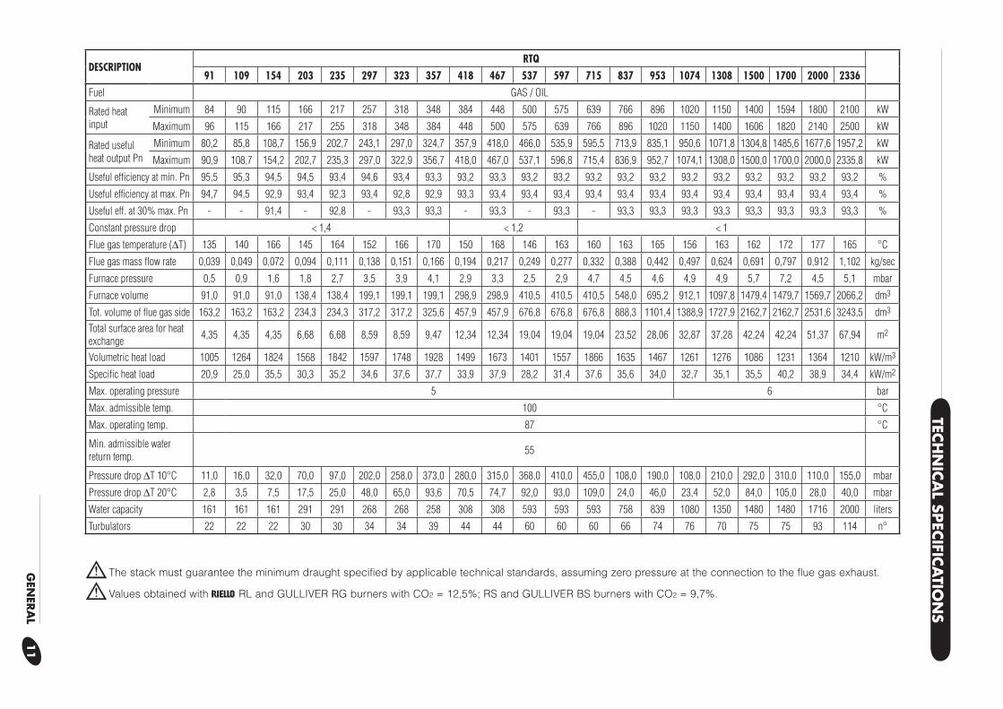
b The stack must guarantee the minimum draught specified by applicable technical standards, assuming zero pressure at the connection to the flue gas exhaust.
b Values obtained with r RL and GULLIVER RG burners with CO2 = 12,5%; RS and GULLIVER BS burners with CO2 = 9,7%.
DESCRIPTIONRTQ
91 109 154 203 235 297 323 357 418 467 537 597 715 837 953 1074 1308 1500 1700 2000 2336Fuel GAS / OIL
Rated heat input
Minimum 84 90 115 166 217 257 318 348 384 448 500 575 639 766 896 1020 1150 1400 1594 1800 2100 kW
Maximum 96 115 166 217 255 318 348 384 448 500 575 639 766 896 1020 1150 1400 1606 1820 2140 2500 kW
Rated useful heat output Pn
Minimum 80,2 85,8 108,7 156,9 202,7 243,1 297,0 324,7 357,9 418,0 466,0 535,9 595,5 713,9 835,1 950,6 1071,8 1304,8 1485,6 1677,6 1957,2 kW
Maximum 90,9 108,7 154,2 202,7 235,3 297,0 322,9 356,7 418,0 467,0 537,1 596,8 715,4 836,9 952,7 1074,1 1308,0 1500,0 1700,0 2000,0 2335,8 kW
Useful effi ciency at min. Pn 95,5 95,3 94,5 94,5 93,4 94,6 93,4 93,3 93,2 93,3 93,2 93,2 93,2 93,2 93,2 93,2 93,2 93,2 93,2 93,2 93,2 %
Useful effi ciency at max. Pn 94,7 94,5 92,9 93,4 92,3 93,4 92,8 92,9 93,3 93,4 93,4 93,4 93,4 93,4 93,4 93,4 93,4 93,4 93,4 93,4 93,4 %
Useful eff. at 30% max. Pn - - 91,4 - 92,8 - 93,3 93,3 - 93,3 - 93,3 - 93,3 93,3 93,3 93,3 93,3 93,3 93,3 93,3 %
Constant pressure drop < 1,4 < 1,2 < 1
Flue gas temperature ('T) 135 140 166 145 164 152 166 170 150 168 146 163 160 163 165 156 163 162 172 177 165 °C
Flue gas mass fl ow rate 0,039 0,049 0,072 0,094 0,111 0,138 0,151 0,166 0,194 0,217 0,249 0,277 0,332 0,388 0,442 0,497 0,624 0,691 0,797 0,912 1,102 kg/sec
Furnace pressure 0,5 0,9 1,6 1,8 2,7 3,5 3,9 4,1 2,9 3,3 2,5 2,9 4,7 4,5 4,6 4,9 4,9 5,7 7,2 4,5 5,1 mbar
Furnace volume 91,0 91,0 91,0 138,4 138,4 199,1 199,1 199,1 298,9 298,9 410,5 410,5 410,5 548,0 695,2 912,1 1097,8 1479,4 1479,7 1569,7 2066,2 dm3
Tot. volume of fl ue gas side 163,2 163,2 163,2 234,3 234,3 317,2 317,2 325,6 457,9 457,9 676,8 676,8 676,8 888,3 1101,4 1388,9 1727,9 2162,7 2162,7 2531,6 3243,5 dm3
Total surface area for heat exchange 4,35 4,35 4,35 6,68 6,68 8,59 8,59 9,47 12,34 12,34 19,04 19,04 19,04 23,52 28,06 32,87 37,28 42,24 42,24 51,37 67,94 m2
Volumetric heat load 1005 1264 1824 1568 1842 1597 1748 1928 1499 1673 1401 1557 1866 1635 1467 1261 1276 1086 1231 1364 1210 kW/m3
Specifi c heat load 20,9 25,0 35,5 30,3 35,2 34,6 37,6 37,7 33,9 37,9 28,2 31,4 37,6 35,6 34,0 32,7 35,1 35,5 40,2 38,9 34,4 kW/m2
Max. operating pressure 5 6 bar
Max. admissible temp. 100 °C
Max. operating temp. 87 °C
Min. admissible water return temp. 55
Pressure drop 'T 10°C 11,0 16,0 32,0 70,0 97,0 202,0 258,0 373,0 280,0 315,0 368,0 410,0 455,0 108,0 190,0 108,0 210,0 292,0 310,0 110,0 155,0 mbar
Pressure drop 'T 20°C 2,8 3,5 7,5 17,5 25,0 48,0 65,0 93,6 70,5 74,7 92,0 93,0 109,0 24,0 46,0 23,4 52,0 84,0 105,0 28,0 40,0 mbar
Water capacity 161 161 161 291 291 268 268 258 308 308 593 593 593 758 839 1080 1350 1480 1480 1716 2000 liters
Turbulators 22 22 22 30 30 34 34 39 44 44 60 60 60 66 74 76 70 75 75 93 114 n°
12
START UP
ON
OFF
20
4060
80
100
0 120
20
4060
80
100
0 120
20
4060
80
100
0 120
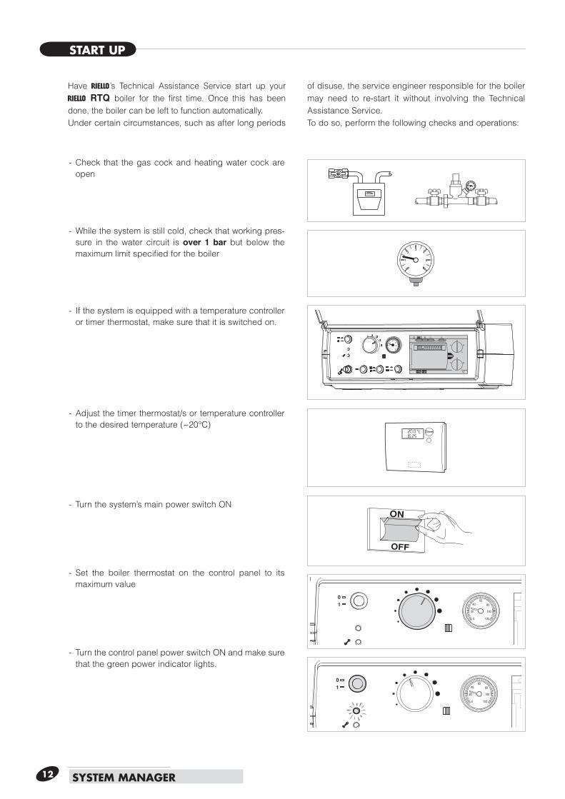
- Check that the gas cock and heating water cock are open
- While the system is still cold, check that working pres-sure in the water circuit is over 1 bar but below the maximum limit specified for the boiler
- If the system is equipped with a temperature controller or timer thermostat, make sure that it is switched on.
- Adjust the timer thermostat/s or temperature controller to the desired temperature (~20°C)
- Turn the system’s main power switch ON
- Set the boiler thermostat on the control panel to its maximum value
- Turn the control panel power switch ON and make sure that the green power indicator lights.
SYSTEM MANAGER
Have r’s Technical Assistance Service start up your r RTQ boiler for the first time. Once this has been done, the boiler can be left to function automatically.Under certain circumstances, such as after long periods
of disuse, the service engineer responsible for the boiler may need to re-start it without involving the Technical Assistance Service.To do so, perform the following checks and operations:
13SYSTEM MANAGER
ON
OFF
20
4060
80
100
0 120
20
4060
80
100
0 120
20
4060
80
100
0 120
The burner should now ignite and remain in operation until the set temperature is reached.The burner will then switch off and on automatically to maintain the set temperature without further operator action.
If any ignition faults or malfunctions occur, the burner performs a “LOCKOUT SHUTDOWN”. This is shown by the red button light on the burner and by the warning light on the control panel.
b If a “LOCKOUT SHUTDOWN” occurs, wait about 30 seconds before resetting the burner.
To reset the burner, press the red button light on the bur-ner and wait until the flame ignites.
Repeat this operation 2-3 times at the most. If the pro-blem persists after that, call r’s Technical Assistance Service.
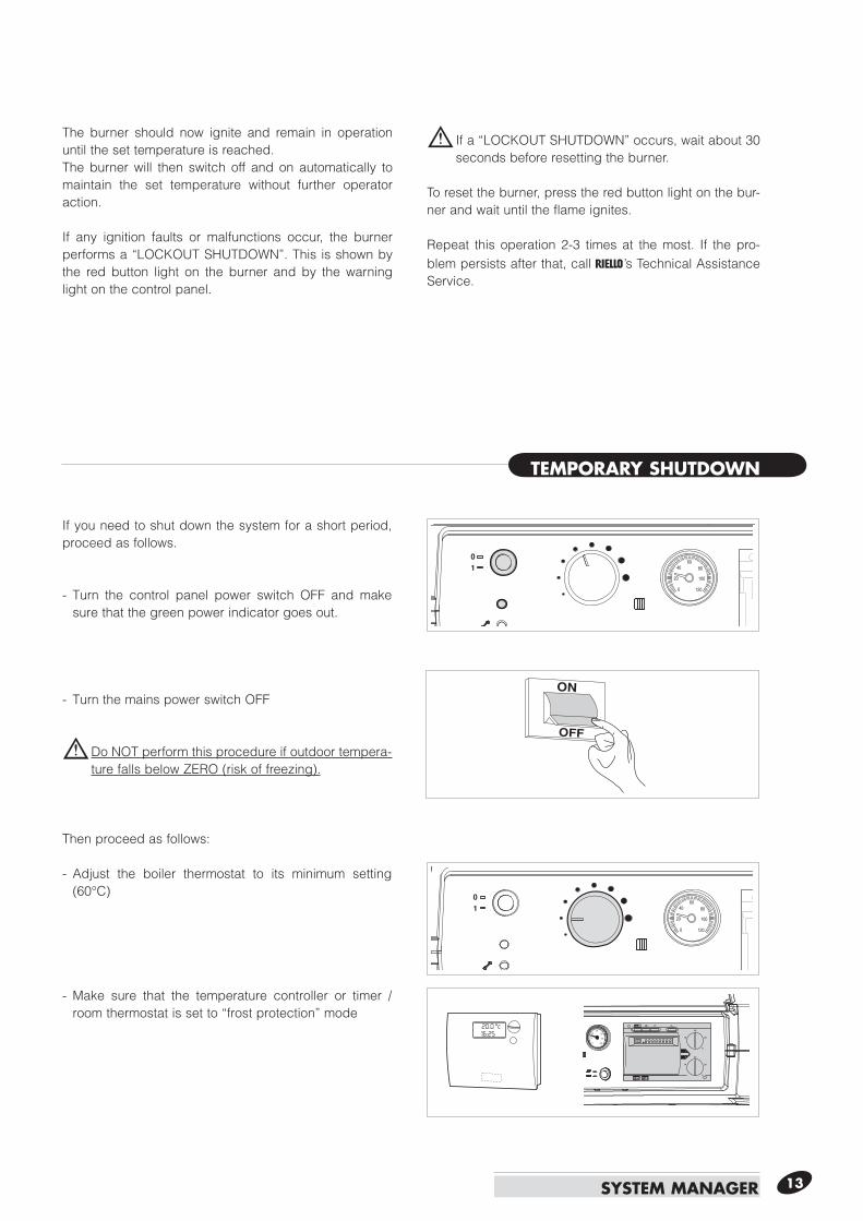
If you need to shut down the system for a short period, proceed as follows.
- Turn the control panel power switch OFF and make sure that the green power indicator goes out.
- Turn the mains power switch OFF
b Do NOT perform this procedure if outdoor tempera-ture falls below ZERO (risk of freezing).
Then proceed as follows:
- Adjust the boiler thermostat to its minimum setting (60°C)
- Make sure that the temperature controller or timer / room thermostat is set to “frost protection” mode
TEMPORARY SHUTDOWN
ON
OFF
b The combustion chamber and flue pipes must be cleaned periodically by r Technical Assistance Service or by a qualified heating engineer (see page 28).
SYSTEM MANAGER14
20
4060
80
100
0 120
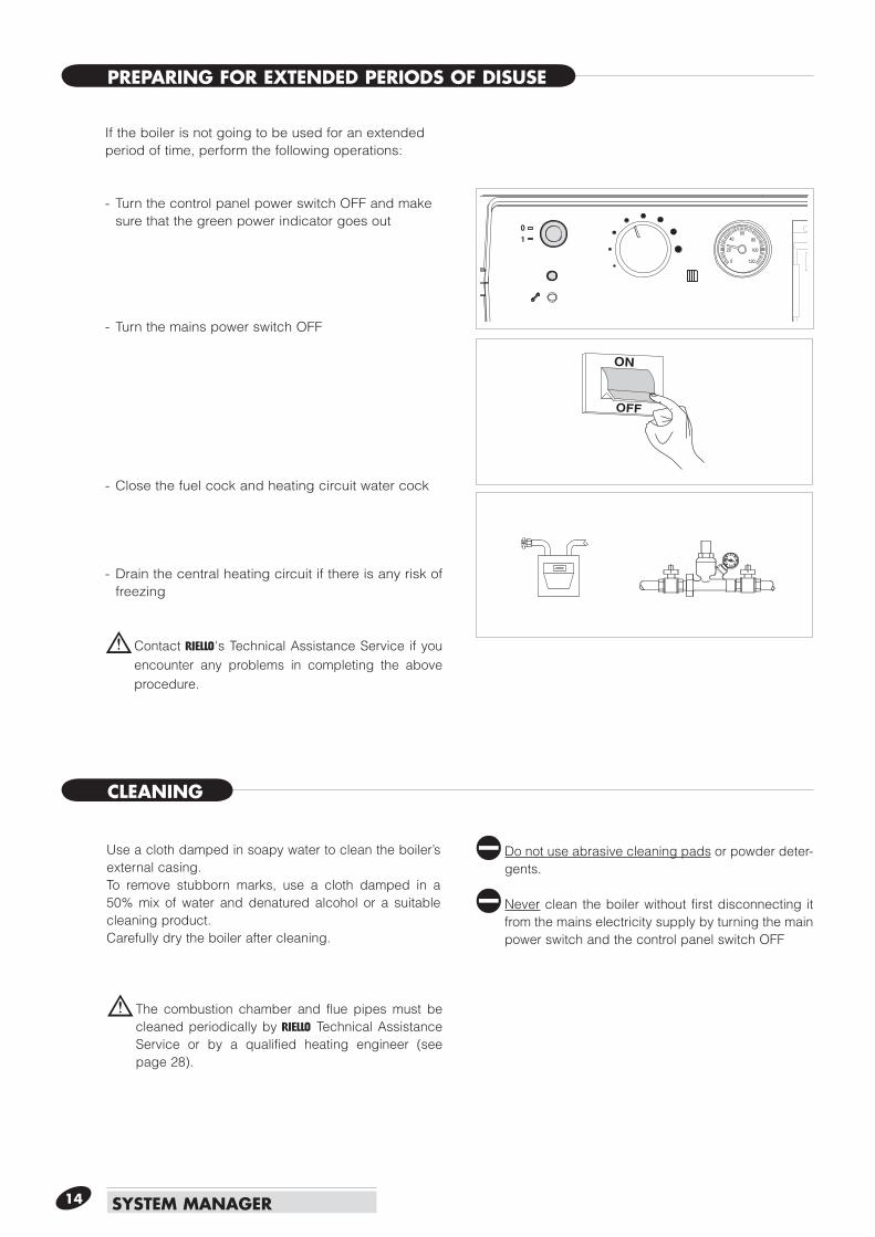
If the boiler is not going to be used for an extended period of time, perform the following operations:
- Turn the control panel power switch OFF and make sure that the green power indicator goes out
- Turn the mains power switch OFF
- Close the fuel cock and heating circuit water cock
- Drain the central heating circuit if there is any risk of freezing
b Contact r's Technical Assistance Service if you encounter any problems in completing the above procedure.
Use a cloth damped in soapy water to clean the boiler’s external casing.To remove stubborn marks, use a cloth damped in a 50% mix of water and denatured alcohol or a suitable cleaning product.Carefully dry the boiler after cleaning.
a Do not use abrasive cleaning pads or powder deter-gents.
a Never clean the boiler without first disconnecting it from the mains electricity supply by turning the main power switch and the control panel switch OFF
PREPARING FOR EXTENDED PERIODS OF DISUSE
CLEANING
MAINTENANCE
USEFUL INFORMATION
15SYSTEM MANAGER
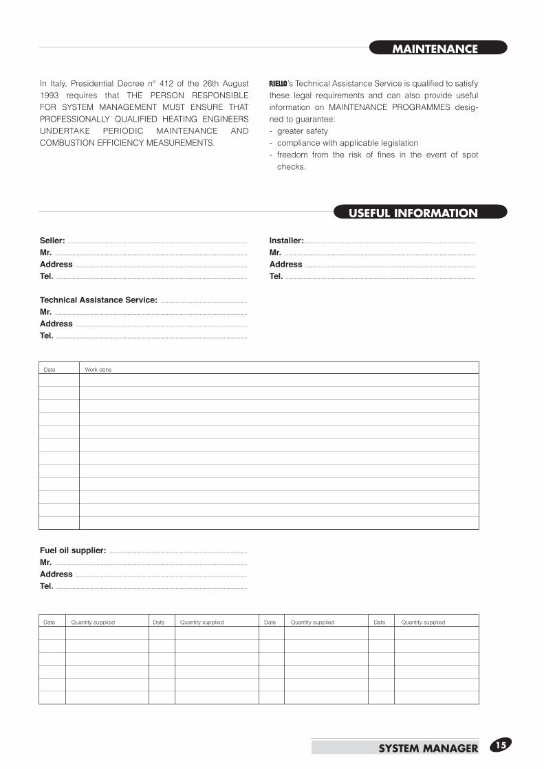
In Italy, Presidential Decree n° 412 of the 26th August 1993 requires that THE PERSON RESPONSIBLE FOR SYSTEM MANAGEMENT MUST ENSURE THAT PROFESSIONALLY QUALIFIED HEATING ENGINEERS UNDERTAKE PERIODIC MAINTENANCE AND COMBUSTION EFFICIENCY MEASUREMENTS.
r’s Technical Assistance Service is qualified to satisfy these legal requirements and can also provide useful information on MAINTENANCE PROGRAMMES desig-ned to guarantee:- greater safety- compliance with applicable legislation- freedom from the risk of fines in the event of spot
checks.
Date Work done
Date Quantity supplied Date Quantity supplied Date Quantity supplied Date Quantity supplied
Seller: ............................................................................................................................................. Mr. .......................................................................................................................................................
Address .......................................................................................................................................
Tel. ......................................................................................................................................................
Technical Assistance Service: ....................................................................
Mr. .......................................................................................................................................................
Address .......................................................................................................................................
Tel. ......................................................................................................................................................
Fuel oil supplier: ............................................................................................................
Mr. .......................................................................................................................................................
Address .......................................................................................................................................
Tel. ......................................................................................................................................................
Installer:....................................................................................................................................... Mr. ......................................................................................................................................................
Address ......................................................................................................................................
Tel. .....................................................................................................................................................
A
16
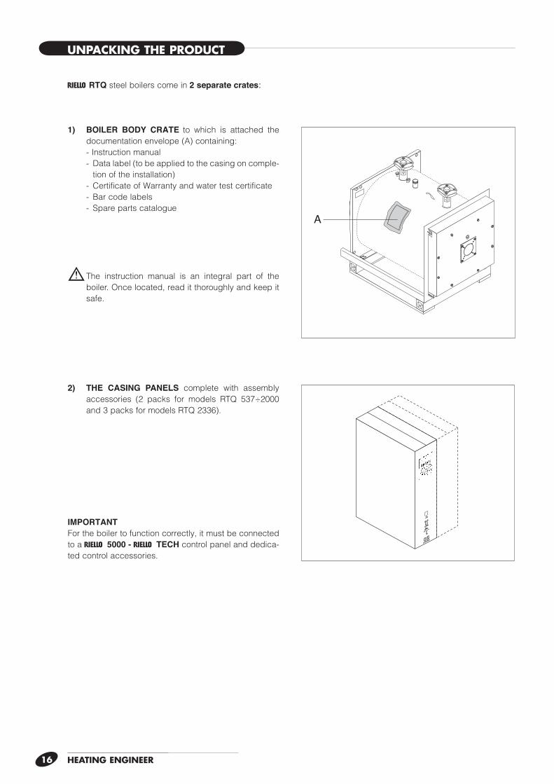
r RTQ steel boilers come in 2 separate crates:
1) BOILER BODY CRATE to which is attached the documentation envelope (A) containing:
- Instruction manual - Data label (to be applied to the casing on comple-
tion of the installation) - Certificate of Warranty and water test certificate - Bar code labels - Spare parts catalogue
b The instruction manual is an integral part of the boiler. Once located, read it thoroughly and keep it safe.
2) THE CASING PANELS complete with assembly accessories (2 packs for models RTQ 537÷2000 and 3 packs for models RTQ 2336).
IMPORTANTFor the boiler to function correctly, it must be connected to a r 5000 - r TECH control panel and dedica-ted control accessories.
HEATING ENGINEER
UNPACKING THE PRODUCT
HEATING ENGINEER 17
OVERALL DIMENSIONS AND WEIGHTS
C
165
AA1
BB1 E
D
100
C
165
AA1
BB1 E
D
100
AA1
C
165
BB1 E
D
100
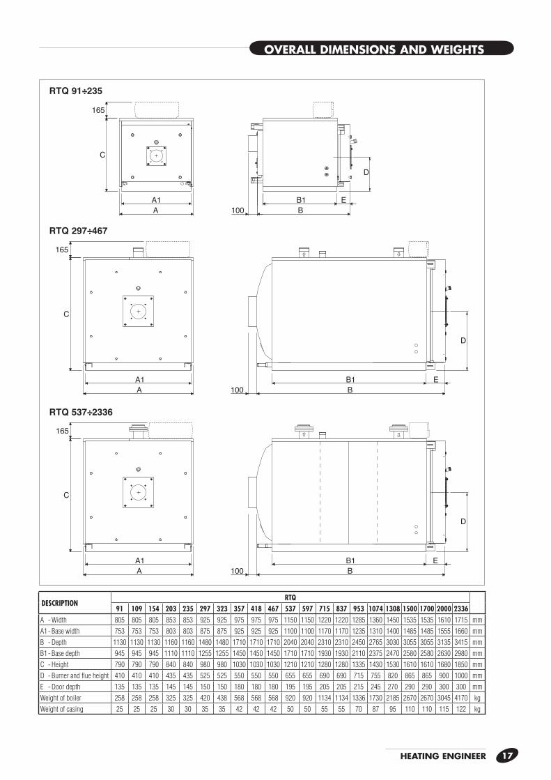
RTQ 91÷235
RTQ 297÷467
RTQ 537÷2336
DESCRIPTIONRTQ
91 109 154 203 235 297 323 357 418 467 537 597 715 837 953 1074 1308 1500 1700 2000 2336A - Width 805 805 805 853 853 925 925 975 975 975 1150 1150 1220 1220 1285 1360 1450 1535 1535 1610 1715 mmA1 - Base width 753 753 753 803 803 875 875 925 925 925 1100 1100 1170 1170 1235 1310 1400 1485 1485 1555 1660 mmB - Depth 1130 1130 1130 1160 1160 1480 1480 1710 1710 1710 2040 2040 2310 2310 2450 2765 3030 3055 3055 3135 3415 mmB1 - Base depth 945 945 945 1110 1110 1255 1255 1450 1450 1450 1710 1710 1930 1930 2110 2375 2470 2580 2580 2630 2980 mmC - Height 790 790 790 840 840 980 980 1030 1030 1030 1210 1210 1280 1280 1335 1430 1530 1610 1610 1680 1850 mmD - Burner and fl ue height 410 410 410 435 435 525 525 550 550 550 655 655 690 690 715 755 820 865 865 900 1000 mmE - Door depth 135 135 135 145 145 150 150 180 180 180 195 195 205 205 215 245 270 290 290 300 300 mmWeight of boiler 258 258 258 325 325 420 438 568 568 568 920 920 1134 1134 1336 1730 2185 2670 2670 3045 4170 kgWeight of casing 25 25 25 30 30 35 35 42 42 42 50 50 55 55 70 87 95 110 110 115 122 kg
HEATING ENGINEER18
HANDLING
PLACE OF INSTALLATION
INSTALLATION IN OLDER SYSTEMS AND SYSTEMS REQUIRING MODERNISATION
r RTQ steel boilers must be installed in a dedicated boiler room, with adequately sized vents, in compliance with applicable laws and standards.
If at all possible, the boiler should be installed on a raised base to prevent the burner fan sucking up dust.
b When installing the boiler, allow sufficient space around it to access all safety and control devices and to permit easy maintenance.
b If the specific weight of the gas supply to the burner is greater than the specific weight of air, install all electrical parts at least 500 mm above floor level.
a Do not install the boiler outdoors. It is not designed to work outdoors and is not fitted with the necessary automatic anti-frost systems to do so.
When installing these boilers in old systems or systems requir-ing modernisation, always perform the following checks:- Make sure that the stack is able to withstand the temperature
of the combustion gases and that it has been designed and made in compliance with applicable standards. The stack must also be as straight as possible, sealed, insulated and not blocked or choked.
- Make sure that the electrical system has been installed by a qualified electrician in compliance with applicable standards.
- Make sure that the oil feed line and any oil storage tank are
made and installed in compliance with applicable standards.- Make sure that the expansion vessels are big enough to con-
tain the volume generated by thermal expansion.- Make sure that flow rate, head and direction of flow of the
pumps are suitable and correct.- Make sure that the circuit has been flushed out to remove all
sludge and lime scale, and has been vented and seal tested.- Make sure that a suitable water treatment system is installed if
the quality of the supply/recirculation water so demands. (See page 19.)
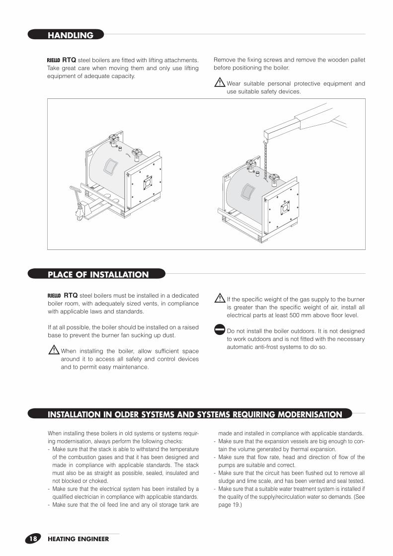
r RTQ steel boilers are fitted with lifting attachments. Take great care when moving them and only use lifting equipment of adequate capacity.
Remove the fixing screws and remove the wooden pallet before positioning the boiler.
b Wear suitable personal protective equipment and use suitable safety devices.
HEATING ENGINEER 19
WATER CONNECTIONS
B
A
E 54/6
10
D
3
1
C
2
AB1001 43
C2
5 6
D
F
AB1001 43
C2
5 6
D
F
G
E
E
G
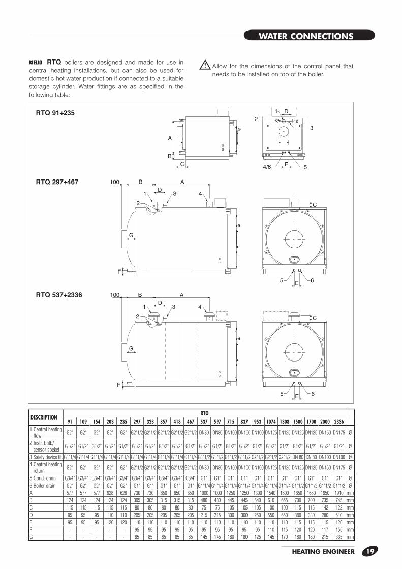
RTQ 91÷235
RTQ 297÷467
RTQ 537÷2336
r RTQ boilers are designed and made for use in central heating installations, but can also be used for domestic hot water production if connected to a suitable storage cylinder. Water fittings are as specified in the following table:
b Allow for the dimensions of the control panel that needs to be installed on top of the boiler.
DESCRIPTIONRTQ
91 109 154 203 235 297 323 357 418 467 537 597 715 837 953 1074 1308 1500 1700 2000 23361 Central heating
flow G2" G2" G2" G2" G2" G2"1/2 G2"1/2 G2"1/2 G2"1/2 G2"1/2 DN80 DN80 DN100 DN100 DN100 DN125 DN125 DN125 DN125 DN150 DN175 Ø
2 Instr. bulb/sensor socket G1/2" G1/2" G1/2" G1/2" G1/2" G1/2" G1/2" G1/2" G1/2" G1/2" G1/2" G1/2" G1/2" G1/2" G1/2" G1/2" G1/2" G1/2" G1/2" G1/2" G1/2" Ø
3 Safety device fit. G1"1/4 G1"1/4 G1"1/4 G1"1/4 G1"1/4 G1"1/4 G1"1/4 G1"1/4 G1"1/4 G1"1/4 G1"1/2 G1"1/2 G1"1/2 G1"1/2 G2"1/2 G2"1/2 G2"1/2 DN 80 DN 80 DN100 DN100 Ø4 Central heating
return G2" G2" G2" G2" G2" G2"1/2 G2"1/2 G2"1/2 G2"1/2 G2"1/2 DN80 DN80 DN100 DN100 DN100 DN125 DN125 DN125 DN125 DN150 DN175 Ø
5 Cond. drain G3/4" G3/4" G3/4" G3/4" G3/4" G3/4" G3/4" G3/4" G3/4" G3/4" G1" G1" G1" G1" G1" G1" G1" G1" G1" G1" G1" Ø6 Boiler drain G2" G2" G2" G2" G2" G1" G1" G1" G1" G1" G1"1/4 G1"1/4 G1"1/4 G1"1/4 G1"1/4 G1"1/4 G1"1/4 G1"1/2 G1"1/2 G1"1/2 G1"1/2 ØA 577 577 577 628 628 730 730 850 850 850 1000 1000 1250 1250 1300 1540 1600 1650 1650 1650 1910 mmB 124 124 124 124 124 305 305 315 315 315 480 480 445 445 540 610 655 700 700 735 745 mmC 115 115 115 115 115 80 80 80 80 80 75 75 105 105 105 100 100 115 115 142 122 mmD 95 95 95 110 110 205 205 205 205 205 215 215 300 300 250 550 650 380 380 280 510 mmE 95 95 95 120 120 110 110 110 110 110 110 110 110 110 110 110 110 115 115 115 120 mmF - - - - - 95 95 95 95 95 95 95 95 95 95 110 115 120 120 117 155 mmG - - - - - 85 85 85 85 85 145 145 180 180 125 145 170 180 180 215 335 mm
HEATING ENGINEER20
32 2
3
33453
8
10 151013
14
12
1
EAF
EAF15
6
33
3 3
11
6 717 5
33
35
34
35
34
D
3÷5 D
DRAINS
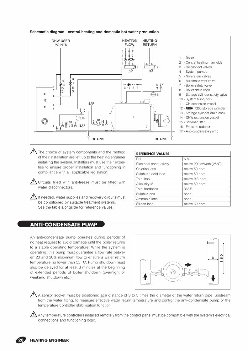
b The choice of system components and the method of their installation are left up to the heating engineer installing the system. Installers must use their exper-tise to ensure proper installation and functioning in compliance with all applicable legislation.
b Circuits filled with anti-freeze must be fitted with water disconnectors.
b If needed, water supplies and recovery circuits must be conditioned by suitable treatment systems.
See the table alongside for reference values.
b A sensor socket must be positioned at a distance of 3 to 5 times the diameter of the water return pipe, upstream from the water fitting, to measure effective water return temperature and control the anti-condensate pump or the temperature controller stabilisation function.
b Any temperature controllers installed remotely from the control panel must be compatible with the system’s electrical connections and functioning logic.
ANTI-CONDENSATE PUMP
Schematic diagram - central heating and domestic hot water production
An anti-condensate pump operates during periods of no heat request to avoid damage until the boiler returns to a stable operating temperature. While the system is operating, this pump must guarantee a flow rate betwe-en 20 and 30% maximum flow to ensure a water return temperature no lower than 55 °C. Pump shutdown must also be delayed for at least 3 minutes at the beginning of extended periods of boiler shutdown (overnight or weekend shutdown etc.).
REFERENCE VALUESPH 6-8Electrical conductivity below 200 mV/cm (25°C)Chlorine ions below 50 ppmSulphuric acid ions below 50 ppmTotal iron below 0,3 ppmAlkalinity M below 50 ppmTotal hardness 35° FSulphur ions noneAmmonia ions noneSilicon ions below 30 ppm
DRAINS
HEATING FLOW
HEATING RETURN
DHW USER POINTS
1 - Boiler2 - Central heating manifolds3 - Disconnect valves4 - System pumps5 - Non-return valves6 - Automatic vent valve7 - Boiler safety valve8 - Boiler drain cock9 - Storage cylinder safety valve10 - System filling cock11 - CH expansion vessel12 - r 7200 storage cylinder13 - Storage cylinder drain cock14 - DHW expansion vessel15 - Softener filter16 - Pressure reducer17 - Anti-condensate pump
HEATING ENGINEER 21
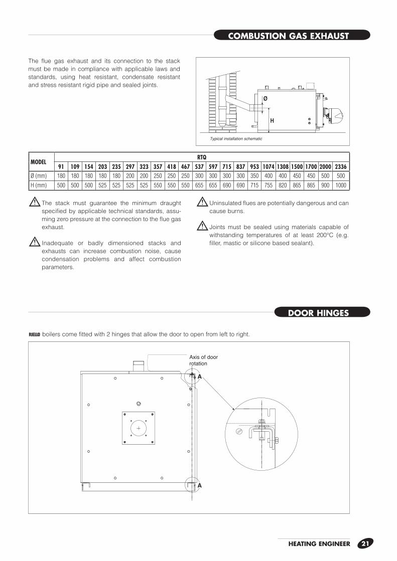
COMBUSTION GAS EXHAUST
DOOR HINGES
H
0
3030
60609090
Ø
r boilers come fitted with 2 hinges that allow the door to open from left to right.
A
A
assedi rotazione
Typical installation schematic
The flue gas exhaust and its connection to the stack must be made in compliance with applicable laws and standards, using heat resistant, condensate resistant and stress resistant rigid pipe and sealed joints.
b The stack must guarantee the minimum draught specified by applicable technical standards, assu-ming zero pressure at the connection to the flue gas exhaust.
b Inadequate or badly dimensioned stacks and exhausts can increase combustion noise, cause condensation problems and affect combustion parameters.
b Uninsulated flues are potentially dangerous and can cause burns.
b Joints must be sealed using materials capable of withstanding temperatures of at least 200°C (e.g. filler, mastic or silicone based sealant).
Axis of door rotation
MODELRTQ
91 109 154 203 235 297 323 357 418 467 537 597 715 837 953 1074 1308 1500 1700 2000 2336Ø (mm) 180 180 180 180 180 200 200 250 250 250 300 300 300 300 350 400 400 450 450 500 500
H (mm) 500 500 500 525 525 525 525 550 550 550 655 655 690 690 715 755 820 865 865 900 1000
HEATING ENGINEER22
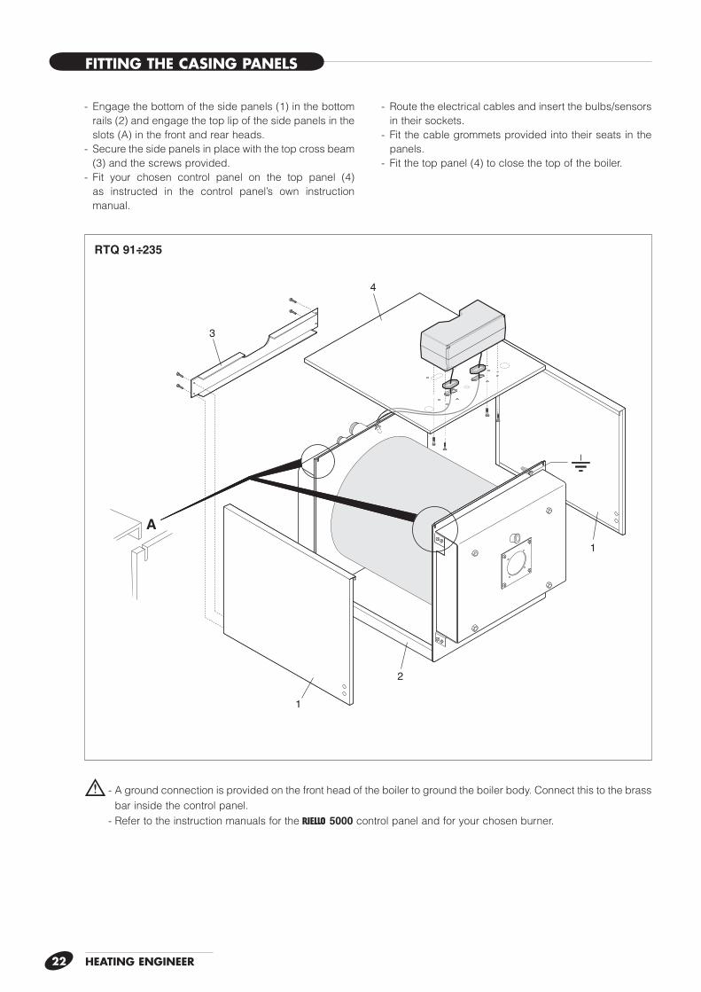
b - A ground connection is provided on the front head of the boiler to ground the boiler body. Connect this to the brass bar inside the control panel.
- Refer to the instruction manuals for the r 5000 control panel and for your chosen burner.
A
1
1
3
4
2
RTQ 91÷235
- Engage the bottom of the side panels (1) in the bottom rails (2) and engage the top lip of the side panels in the slots (A) in the front and rear heads.
- Secure the side panels in place with the top cross beam (3) and the screws provided.
- Fit your chosen control panel on the top panel (4) as instructed in the control panel’s own instruction manual.
- Route the electrical cables and insert the bulbs/sensors in their sockets.
- Fit the cable grommets provided into their seats in the panels.
- Fit the top panel (4) to close the top of the boiler.
FITTING THE CASING PANELS
HEATING ENGINEER 23
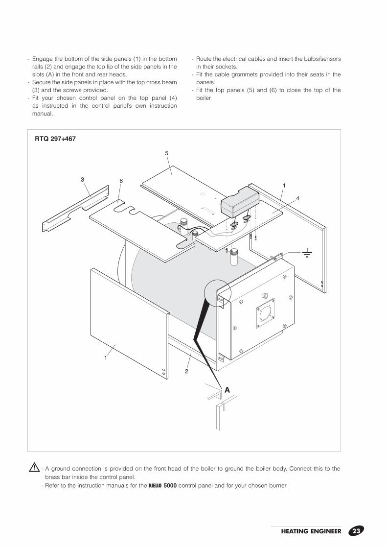
- Engage the bottom of the side panels (1) in the bottom rails (2) and engage the top lip of the side panels in the slots (A) in the front and rear heads.
- Secure the side panels in place with the top cross beam (3) and the screws provided.
- Fit your chosen control panel on the top panel (4) as instructed in the control panel’s own instruction manual.
- Route the electrical cables and insert the bulbs/sensors in their sockets.
- Fit the cable grommets provided into their seats in the panels.
- Fit the top panels (5) and (6) to close the top of the boiler.
b - A ground connection is provided on the front head of the boiler to ground the boiler body. Connect this to the brass bar inside the control panel.
- Refer to the instruction manuals for the r 5000 control panel and for your chosen burner.
A
1
2
1
5
6
4
3
RTQ 297÷467
HEATING ENGINEER24
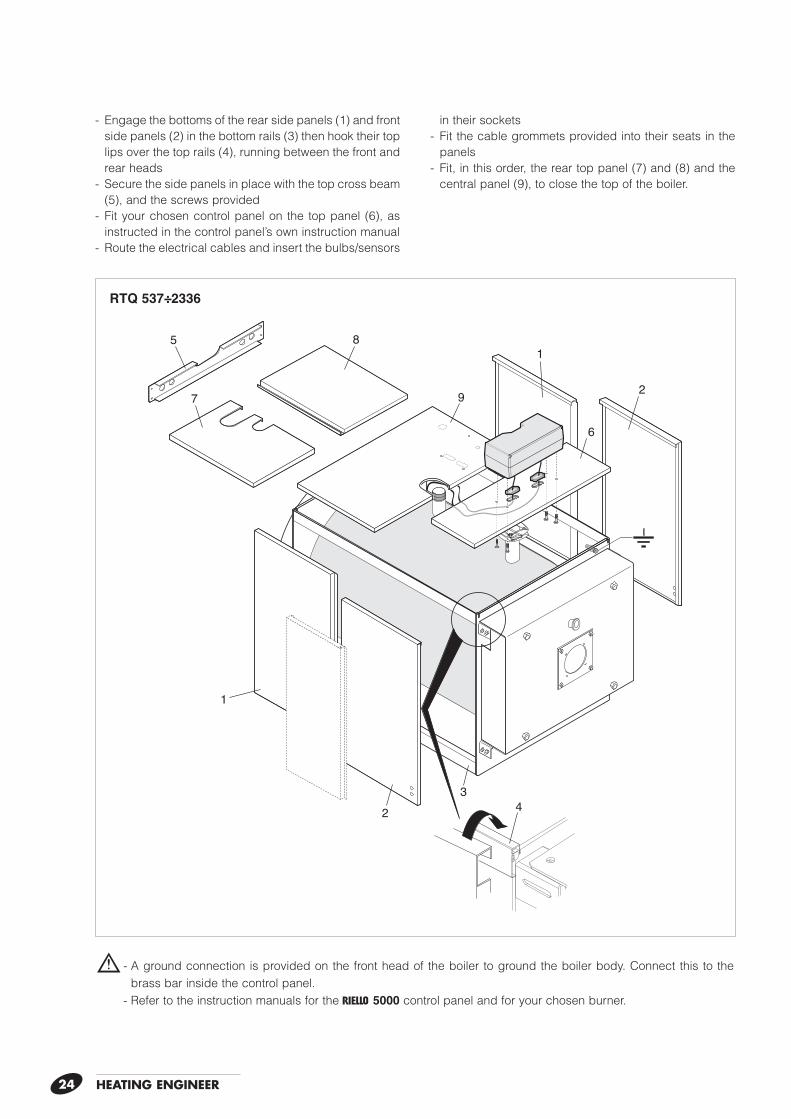
b - A ground connection is provided on the front head of the boiler to ground the boiler body. Connect this to the brass bar inside the control panel.
- Refer to the instruction manuals for the r 5000 control panel and for your chosen burner.
4
1
23
2
1
9
85
7
6
RTQ 537÷2336
- Engage the bottoms of the rear side panels (1) and front side panels (2) in the bottom rails (3) then hook their top lips over the top rails (4), running between the front and rear heads
- Secure the side panels in place with the top cross beam (5), and the screws provided
- Fit your chosen control panel on the top panel (6), as instructed in the control panel’s own instruction manual
- Route the electrical cables and insert the bulbs/sensors
in their sockets- Fit the cable grommets provided into their seats in the
panels- Fit, in this order, the rear top panel (7) and (8) and the
central panel (9), to close the top of the boiler.
25TECHNICAL ASSISTANCE SERVICE
PREPARING FOR INITIAL START-UP
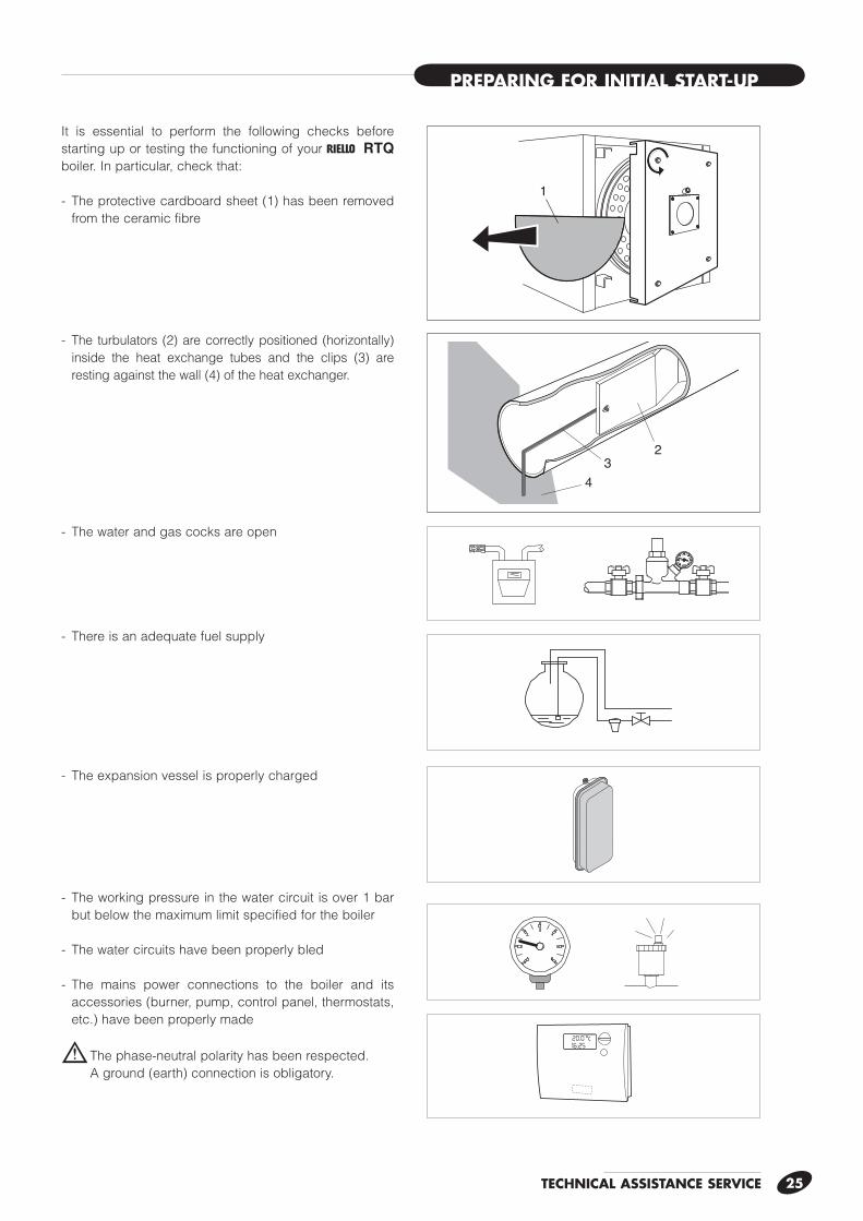
It is essential to perform the following checks before starting up or testing the functioning of your r RTQ boiler. In particular, check that:
- The protective cardboard sheet (1) has been removed from the ceramic fibre
- The turbulators (2) are correctly positioned (horizontally) inside the heat exchange tubes and the clips (3) are resting against the wall (4) of the heat exchanger.
- The water and gas cocks are open
- There is an adequate fuel supply
- The expansion vessel is properly charged
- The working pressure in the water circuit is over 1 bar but below the maximum limit specified for the boiler
- The water circuits have been properly bled
- The mains power connections to the boiler and its accessories (burner, pump, control panel, thermostats, etc.) have been properly made
b The phase-neutral polarity has been respected. A ground (earth) connection is obligatory.
1
23
4
TECHNICAL ASSISTANCE SERVICE26
ON
OFF
20
4060
80
100
0 120
20
4060
80
100
0 120
20
4060
80
100
0 120
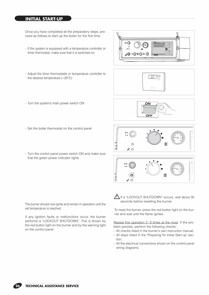
Once you have completed all the preparatory steps, pro-ceed as follows to start up the boiler for the first time:
- If the system is equipped with a temperature controller or timer thermostat, make sure that it is switched on
- Adjust the timer thermostat/s or temperature controller to the desired temperature (~20°C)
- Turn the system’s main power switch ON
- Set the boiler thermostat on the control panel
- Turn the control panel power switch ON and make sure that the green power indicator lights
The burner should now ignite and remain in operation until the set temperature is reached.
If any ignition faults or malfunctions occur, the burner performs a “LOCKOUT SHUTDOWN”. This is shown by the red button light on the burner and by the warning light on the control panel.
b If a “LOCKOUT SHUTDOWN” occurs, wait about 30 seconds before resetting the burner.
To reset the burner, press the red button light on the bur-ner and wait until the flame ignites.
Repeat this operation 2 -3 times at the most. If the pro-blem persists, perform the following checks:- All checks listed in the burner's own instruction manual;- All steps listed in the ‘Preparing for Initial Start-up’ sec-
tion;- All the electrical connections shown on the control panel
wiring diagrams.
INITIAL START-UP
TECHNICAL ASSISTANCE SERVICE 27
CHECKS DURING AND AFTER INITIAL START-UP
Flame inspection window cooling
Pressure measure-ment point
ON
OFF
20
4060
80
100
0 120
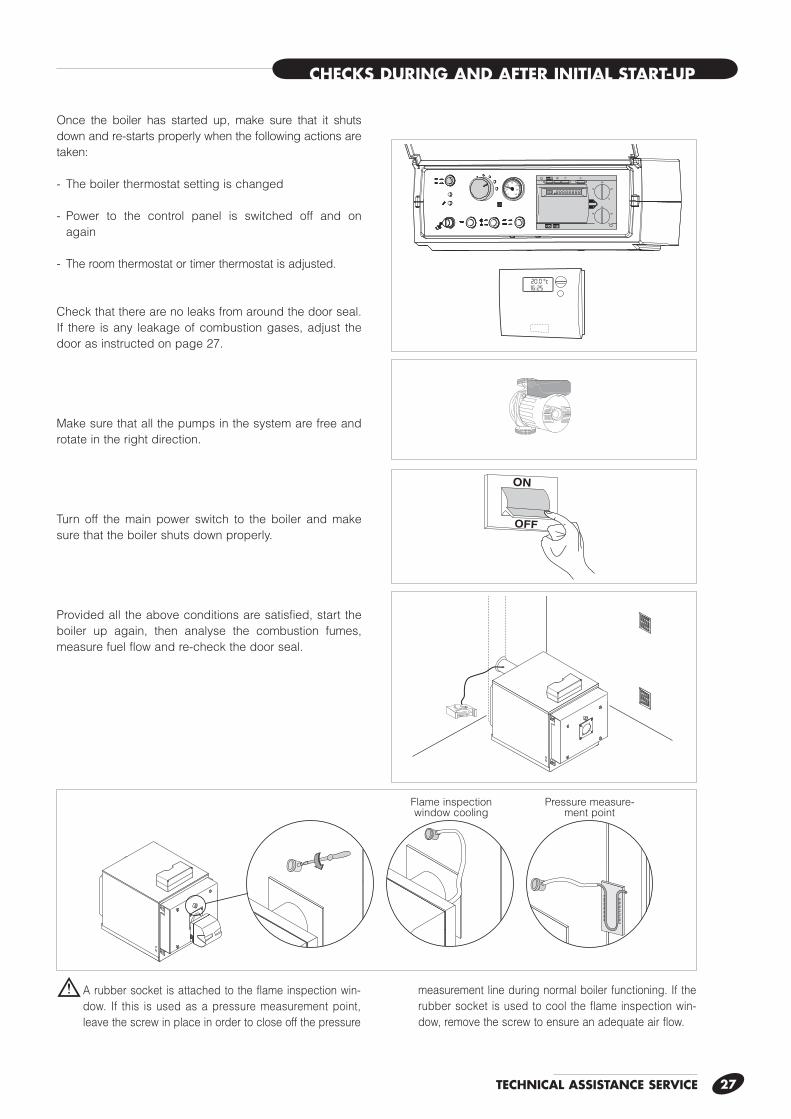
Once the boiler has started up, make sure that it shuts down and re-starts properly when the following actions are taken:
- The boiler thermostat setting is changed
- Power to the control panel is switched off and on again
- The room thermostat or timer thermostat is adjusted.
Check that there are no leaks from around the door seal. If there is any leakage of combustion gases, adjust the door as instructed on page 27.
Make sure that all the pumps in the system are free and rotate in the right direction.
Turn off the main power switch to the boiler and make sure that the boiler shuts down properly.
Provided all the above conditions are satisfied, start the boiler up again, then analyse the combustion fumes, measure fuel flow and re-check the door seal.
b A rubber socket is attached to the flame inspection win-dow. If this is used as a pressure measurement point, leave the screw in place in order to close off the pressure
measurement line during normal boiler functioning. If the rubber socket is used to cool the flame inspection win-dow, remove the screw to ensure an adequate air flow.
TECHNICAL ASSISTANCE SERVICE28
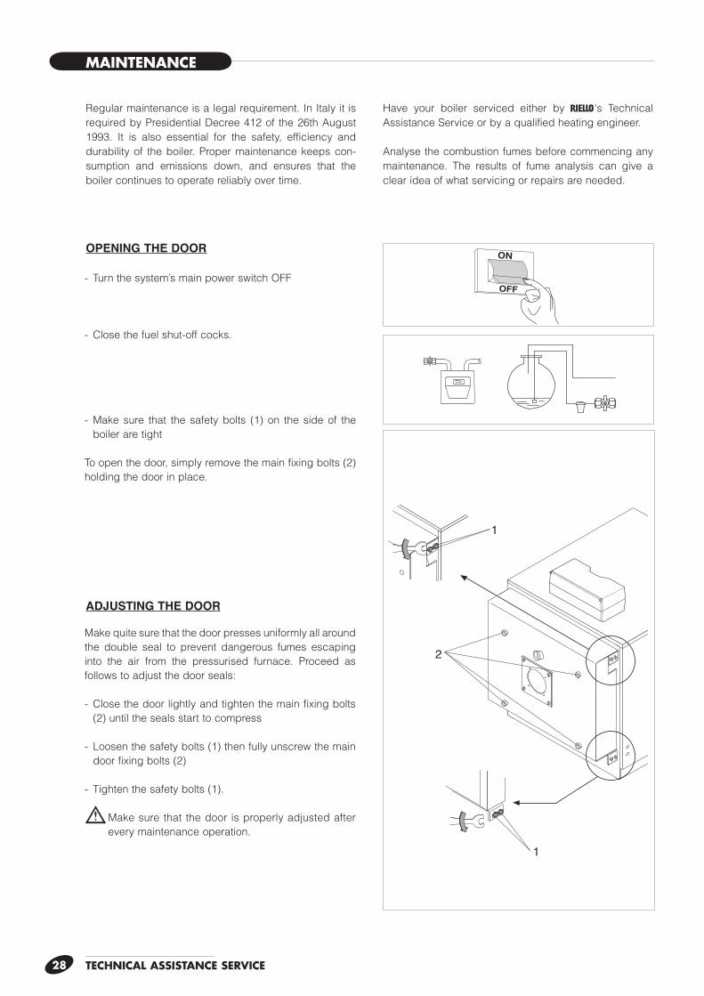
MAINTENANCE
OPENING THE DOOR
ADJUSTING THE DOOR
Regular maintenance is a legal requirement. In Italy it is required by Presidential Decree 412 of the 26th August 1993. It is also essential for the safety, efficiency and durability of the boiler. Proper maintenance keeps con-sumption and emissions down, and ensures that the boiler continues to operate reliably over time.
Have your boiler serviced either by r's Technical Assistance Service or by a qualified heating engineer.
Analyse the combustion fumes before commencing any maintenance. The results of fume analysis can give a clear idea of what servicing or repairs are needed.
ON
OFF
1
2
1
- Turn the system’s main power switch OFF
- Close the fuel shut-off cocks.
- Make sure that the safety bolts (1) on the side of the boiler are tight
To open the door, simply remove the main fixing bolts (2) holding the door in place.
Make quite sure that the door presses uniformly all around the double seal to prevent dangerous fumes escaping into the air from the pressurised furnace. Proceed as follows to adjust the door seals:
- Close the door lightly and tighten the main fixing bolts (2) until the seals start to compress
- Loosen the safety bolts (1) then fully unscrew the main door fixing bolts (2)
- Tighten the safety bolts (1).
b Make sure that the door is properly adjusted after every maintenance operation.
TECHNICAL ASSISTANCE SERVICE 29
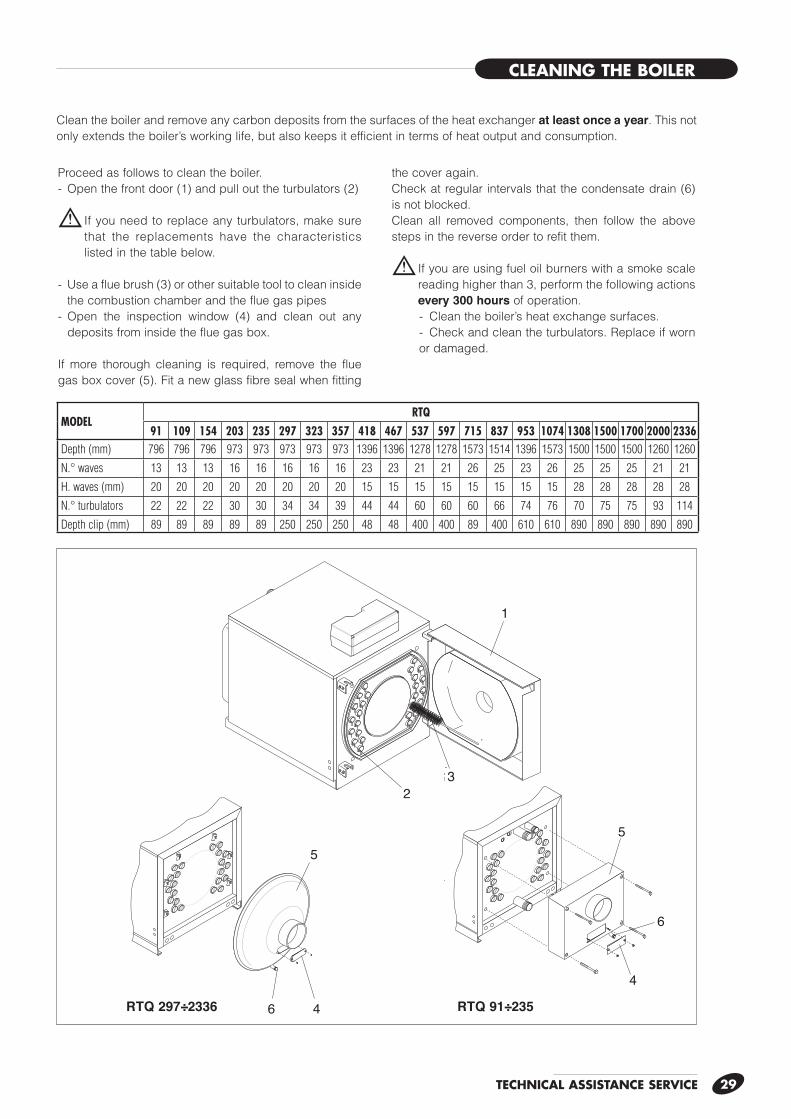
CLEANING THE BOILER
Proceed as follows to clean the boiler.- Open the front door (1) and pull out the turbulators (2)
b If you need to replace any turbulators, make sure that the replacements have the characteristics listed in the table below.
- Use a flue brush (3) or other suitable tool to clean inside the combustion chamber and the flue gas pipes
- Open the inspection window (4) and clean out any deposits from inside the flue gas box.
If more thorough cleaning is required, remove the flue gas box cover (5). Fit a new glass fibre seal when fitting
the cover again.Check at regular intervals that the condensate drain (6) is not blocked.Clean all removed components, then follow the above steps in the reverse order to refit them.
b If you are using fuel oil burners with a smoke scale reading higher than 3, perform the following actions every 300 hours of operation.- Clean the boiler’s heat exchange surfaces.- Check and clean the turbulators. Replace if worn or damaged.
1
2
4
4
6
6
55
3
Clean the boiler and remove any carbon deposits from the surfaces of the heat exchanger at least once a year. This not only extends the boiler’s working life, but also keeps it efficient in terms of heat output and consumption.
RTQ 297÷2336 RTQ 91÷235
MODELRTQ
91 109 154 203 235 297 323 357 418 467 537 597 715 837 953 1074 1308 1500 1700 2000 2336Depth (mm) 796 796 796 973 973 973 973 973 1396 1396 1278 1278 1573 1514 1396 1573 1500 1500 1500 1260 1260
N.° waves 13 13 13 16 16 16 16 16 23 23 21 21 26 25 23 26 25 25 25 21 21
H. waves (mm) 20 20 20 20 20 20 20 20 15 15 15 15 15 15 15 15 28 28 28 28 28
N.° turbulators 22 22 22 30 30 34 34 39 44 44 60 60 60 66 74 76 70 75 75 93 114
Depth clip (mm) 89 89 89 89 89 250 250 250 48 48 400 400 89 400 610 610 890 890 890 890 890
TECHNICAL ASSISTANCE SERVICE30
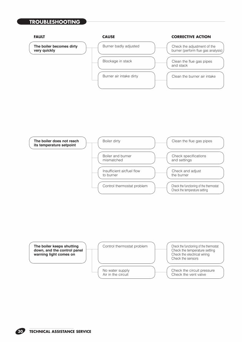
FAULT CAUSE CORRECTIVE ACTION
Control thermostat problemThe boiler keeps shutting down, and the control panel warning light comes on
Check the functioning of the thermostat Check the temperature setting Check the electrical wiring Check the sensors
No water supply Air in the circuit
Check the circuit pressure Check the vent valve
Boiler dirty Clean the flue gas pipes
Boiler and burner mismatched
Check specifications and settings
Insufficient air/fuel flow to burner
Check and adjust the burner
Control thermostat problem Check the functioning of the thermostat Check the temperature setting
The boiler does not reach its temperature setpoint
The boiler becomes dirty very quickly
Burner badly adjusted
Blockage in stack
Burner air intake dirty
Check the adjustment of the burner (perform flue gas analysis)
Clean the flue gas pipes and stack
Clean the burner air intake
TROUBLESHOOTING
TECHNICAL ASSISTANCE SERVICE 31
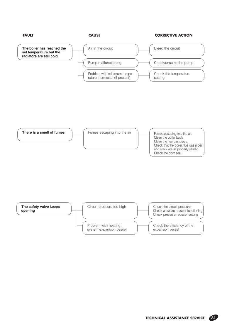
FAULT CAUSE CORRECTIVE ACTION
Air in the circuitThe boiler has reached the set temperature but the radiators are still cold
Bleed the circuit
Pump malfunctioning Check/unseize the pump
Problem with minimum tempe- rature thermostat (if present)
Check the temperature setting
Fumes escaping into the airThere is a smell of fumes Fumes escaping into the air. Clean the boiler body. Clean the flue gas pipes. Check that the boiler, flue gas pipes and stack are all properly sealed Check the door seal.
Circuit pressure too highThe safety valve keeps opening
Check the circuit pressure Check pressure reducer functioning Check pressure reducer setting
Problem with heating system expansion vessel
Check the efficiency of the expansion vessel

RIELLO S.p.A. - 37045 Legnago (VR) Tel. 0442630111 - Fax 044222378 - www.riello.it
The manufacturer strives to continuously improve all products. Appearance, dimensions, technical specifications, standard equipment and accessories
are therefore liable to modification without notice.
Co
d.
20
01
79
04