Embed Size (px)
Citation preview

Part-2, “Mathematical model of vapor condensation on curvilinear surface under microgravity condition taking into account heat conductivity in the condenser wall”
1
Steam condensation on a non-isothermal extended Gregorig-Ademek surface
I.V. Marchuk1, О.А. Kabov1,3, Yu.V. Lyulin1 , J-C. Legros2,3 and researchers from EHP2
1- Institute of Thermophysics, Novosibirsk, Russia 2- Euro Heat Pipes S.A., Brussels, Belgium 3- Microgravity Research Center, Université Libre de Bruxelles C.P. 165/62, B-1050, Belgium Abstract Model of stationary steam condensation on curvilinear fins of various shapes is examined under condition of capillary pressure having determining effect on the condensate film motion. The fins are described by an equation for a spiral with a variable direction of rotation. Thermal conductivity in the wall is taken into account. The initial system of the equations is reduced to the Laplace equation with the nonlinear boundary condition. The algorithm of the numerical calculation is realized using finite-difference approximation, successive over relaxation iterative method and explicit approximation of nonlinear term. The influence of various parameters on intensity of the condensation is analyzed. The numerical calculations have shown that when using fins with optimal shape the reduction of the condensate flow is 50-80 %, compared to isothermal case, depending on the thermal conductivity coefficient and fin geometrical shape. Keywords: condensation, heat transfer enhancement, wall thermal conductivity 1. Introduction
It is known, that use of finned surfaces in condensers essentially increases intensity of condensation [1]. Increase of the condensate mass flow from the finned surface in comparison with smooth one occurs not only because of the increase of the surface area, but also due to reduction of the film thickness at the fin peaks caused by capillary forces. The search of an optimum fin shape was undertaken in a number of papers. Gregorig [2] considered a fin with such a shape that the condensate film flowing down the fin had constant thickness. Then Zener and Lavi [3] found such a fin shape that the change of condensate film surface curvature provided constant gradient of the capillary pressure, and they stated that exactly in this case maximum of condensate mass flow from the fin is achieved. The most systematical investigation was executed by Adamek [4], where the search of the optimum fin shapes was performed among parametrical family of curves including particular cases of the Gregorig and Zener-Lavi shapes. The optimum fin shapes from this family were found.
The theoretical investigation of stationary steam condensation on curvilinear fins described by an equation for a spiral with a variable direction of rotation started in [2] was continued in the previous paper of the authors [5]. It was proposed to extend the well-known surfaces of condensation proposed in [2-4] to obtain more optimal fins. The fin shape obtained has made it possible to increase the length of the surface at which the condensate film moves under the action of the capillary pressure gradient by 73 percent and more. Mathematical analysis and numerical calculations were carried out for the case when the condensate was drawn away from the center of a flute. The properties of these surfaces, which are described in the general case by four parameters, have been analyzed. The effects of these parameters on the intensity of heat transfer have been analyzed analytically and numerically. At the use of an extended surface that can be manufactured by traditional methods, the condensate flux can be by 62% greater than at the use of the surface proposed in [4].
In all above-mentioned papers, temperature of the fin surface was assumed constant. Since at film condensation of the steam heat transfer coefficient is relatively high, this assumption corresponds to infinite thermal conductivity coefficient of the fin material. Actually, the fin surface is not isothermal, and intensity of condensation can essentially depend on real values of thermal
Part-2, “Mathematical model of vapor condensation on curvilinear surface under microgravity condition taking into account heat conductivity in the condenser wall”
2
conductivity coefficient. The optimum fin shapes obtained for isothermal case are not optimum for non-isothermal case. The choice of an optimum fin shape apparently should be based on models taking into account this factor.
The purpose of this work is to analyze influence of the wall thermal conductivity on intensity of condensation on curvilinear fins from family of fins described in [4], and to find optimum shapes in case of a non-isothermal fin. 2. Problem statement and derivation of basic relations 2.1 Condensation on non-isothermal surface.
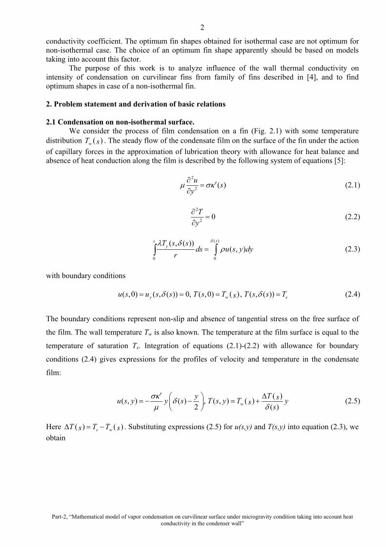
We consider the process of film condensation on a fin (Fig. 2.1) with some temperature distribution ( )wT s . The steady flow of the condensate film on the surface of the fin under the action of capillary forces in the approximation of lubrication theory with allowance for heat balance and absence of heat conduction along the film is described by the following system of equations [5]:
2
2 ( )u sy
∂ ′=∂
µ σκ (2.1)
2
2 0Ty
∂=
∂ (2.2)
( )
0 0
( , ( ))( , )
ssyT s s
ds u s y dyr
=∫ ∫δλ δ
ρ (2.3)
with boundary conditions ( )( ,0) ( , ( )) 0, ( ,0) , ( , ( ))y w su s u s s T s T T s s Ts= = = =δ δ (2.4)
The boundary conditions represent non-slip and absence of tangential stress on the free surface of
the film. The wall temperature Tw is also known. The temperature at the film surface is equal to the
temperature of saturation Ts. Integration of equations (2.1)-(2.2) with allowance for boundary
conditions (2.4) gives expressions for the profiles of velocity and temperature in the condensate
film:
( ) ( )( , ) ( ) , ( , )2 ( )wy T su s y y s T s y T ys
s′ ∆ = − − = +
σκ δµ δ
(2.5)
Here ( ) ( )s wT T Ts s∆ = − . Substituting expressions (2.5) for u(s,y) and T(s,y) into equation (2.3), we obtain

Part-2, “Mathematical model of vapor condensation on curvilinear surface under microgravity condition taking into account heat conductivity in the condenser wall”
3
δ s
S
Y
y
ω
X
∆T=0
P
( )( )w
T T sn s
∂ ∆=
∂λ λ
δ
0XT =
0T T=
0XT =
Fig. 2.1. Extended surface of finning (system of coordinates).
( )3
1
0
( )( )3
s sT s dssr
− ′∆ = −∫
λ ρσκ δδµ
(2.6)
Integration method for equation (2.6) is similar to that from [5]. Finally we get expression for condensate film thickness
( ) ( )( ) ( ) ( )( )1
41 3 1 3
0
4s Ts s d
rλ µτδ κ κ τ τ
ρσ− ∆′ ′= − −
∫ (2.7)
The following expression for the condensate flow along the fin can be obtained from (2.6) and (2.7):
( ) ( )( )3
41 3
0
( )43
s Tm s dr
ρσ λ τ µ κ τ τµ ρσ
∆ ′= −
∫ (2.8)
It should be noticed that the expressions obtained are similar to those for isothermal surface. The only difference is that T∆ depends on s . 2.2 Thermal conductivity in the fin body.
The stationary distribution of temperature in the fin body should satisfy to the equation
2 2
2 2 0T TX Y
∂ ∂+ =
∂ ∂ (2.9)
with boundary condition at the bottom part of the surface 0( ,0))T x T= (2.10)

Part-2, “Mathematical model of vapor condensation on curvilinear surface under microgravity condition taking into account heat conductivity in the condenser wall”
4
and from reasons of symmetry
( ) ( ),0 ,0, 0T TY Y P
X X∂ ∂
= =∂ ∂
(2.11)
Let the heat flux ( )q s is given on curvilinear surface where condensation takes place
( ), ( )
( )f f
wX X s Y Y s
T q sn
λ= =
∂=
∂ (2.12)
This is a standard two-dimensional boundary problem for the Laplace equation. It is only necessary to connect the value of heat flux density ( )q s with condensation that is described by the equations (2.1)-(2.4). From (2.5) it follows that
( )( )( )
T sq ss
λδ
∆= (2.13)
Thus
( )( )w
T T sn s
λ λδ
∂ ∆=
∂ (2.14)
Using (2.7) we obtain
( ) ( )( ) ( ) ( )( )1
41 3 1 3
0
4s
wT T sT s dsn r
λ µλ λ κ κ τ τρσ
− ∂ ∆′ ′= ∆ − − ∂
∫ (2.15)
We have obtained boundary problem for the Laplace equation (2.9)-(2.11) with non-linear boundary condition (2.15) on the fin surface where condensation takes place. 3. Numerical algorithm.
Variables in the problem (2.9)-(2.12) can be reduced to dimensionless form using following scales: temperature drop 0 0sT T T∆ = − , maximal linear size of the fin max{ ( ), ( ) }f f wL X S Y S H= + , and scale for heat flux 0 0wq T L= λ ∆ . Equation (2.9) in internal nodes of the grid can be approximated by the difference scheme on a uniform square grid with step h
1, 1, , 1 , 1 ,2
40i j i j i j i j i j
hθ θ θ θ θ− + − ++ + + −
= (3.1)
Boundary conditions can be approximated as follows equation (2.10) , 0
mi Jθ = , (3.2) conditions (2.11) 0, 1,j jθ θ= , , 1,m mI j I jθ θ −= , (3.3) according to (2.12), for the nodes of curvilinear boundary we obtain

Part-2, “Mathematical model of vapor condensation on curvilinear surface under microgravity condition taking into account heat conductivity in the condenser wall”
5
( ) ( ), , 1, , 1sin cos sin cosi j i j i j i jq hθ θ θ− += + Θ + Θ Θ + Θ (3.4) and the temperature at the boundary is calculated with the help of linear approximation ( ), , , , ,( )sin ( ) cosb f f
i j i j i j i j i jq x ih y jhθ θ= + − Θ + + Θ (3.5)
Here , ,,f fi j i jx y are the dimensionless coordinates of the node nearest to the boundary grid node.
Values ,i jq are calculated according to (2.15), with values of temperature of the fin surface ,bi jθ ,
known from the previous step of iterative algorithm, using for calculating ( )T s∆ . Integral in (2.15) is calculated according to the “rectangular formula”. Intermediate values of ( )T s∆ are linearly interpolated. Calculation algorithm is as follows
1. Initial approximation is set ( )0,i j mh j Jθ = − . It is a linear function depending on Y only.
2. According to (3.5), the temperature ,bi jθ on the curvilinear surface is calculated. For the
temperature ,bi jθ obtained, heat flux density ,i jq is calculated.
3. For heat flux ,i jq updated on the step 2, the norm of residual vector is calculated. If the value of the residual vector norm is less than the given accuracy, the transition to the step 5, finishing iterative process, is executed.
4. For a system of the linear algebraic equations (3.1)-(3.4), the given amount of iterations of SOR method is carried out, and the iterative algorithm is constructed so that the equations (3.2)-(3.4) for boundary conditions are excluded from the system being solved. Transition to the step 2.
5. Calculation results recording on the hard drive. While realization of numerical algorithm, the value of relaxation parameter can be directly set
or calculated according to a technique given in [6], where on the first iterations the relaxation parameter value is set equal to 1 (Seidel method), and quasi-optimum value of the iterative parameter is calculated. 4. Family of curvilinear fins.
In the given work a process of condensation on parametrical family of curvilinear fins with power dependent curvature is considered. Such family of fins for the first time was considered in [4]. Authors of [5] suggested to consider the process of condensation on the extended fins from this family. Extension of the surface was understood as analytical continuation into area of negative curvature (non-convex surfaces). Derivative of curvature, determining the gradient of capillary pressure, looks like ( ) 2
1 1( )s a s S Sξκ −′ = (4.1) curvature
( ) ( ) 1
11 1
( )1a bs s S
S Sξκ
ξ+= +
+ (4.2)
rotation angle
( )( ) ( ) 2
11
( )1 2
a ss s S bS
ξ
ξ ξ+Θ = +
+ + (4.3)

Part-2, “Mathematical model of vapor condensation on curvilinear surface under microgravity condition taking into account heat conductivity in the condenser wall”
6
Parameters determining the curve are the following: ξ - exponent, 1S - curve length up to the inflection point, ω - curve rotation in the inflection point. From conditions 1( ) 0Sκ = , 1( )S ωΘ = , one can obtain the expressions for parameters a and b at 1ξ ≠ − ( )2a ω ξ= − + , ( ) ( )2 1b ω ξ ξ= + + (4.4) if 1ξ = − then a ω= − , 0b = ( )1 1( ) lns a s S Sκ = (4.5) ( )1 1 1( ) lns a s s S S s SΘ = − (4.6) Let fins at 1ξ = − be called logarithmic fins. For an isothermal fin, substitution of (4.1) to (2.7) and (2.8) gives expressions for condensate film thickness, mean heat transfer coefficient and condensate mass flow [5].
( ) ( )( )( )1
41 2 1112 2 3Ts w S s
rξ ξλ µδ ξ ξ
σ ρ− + − ∆
= + +
(4.7)
( ) ( ) ( ) ( ) ( ) ( )1
3 4 43 2 1
1 10
1 12, , , 2 33
s rw S s d w S ss T
ξ ξλ σ ρα ξ τ λ ξ ξδ τ λ µ
− − + − = = + + ∆
∫ (4.8)
( ) ( )( )( )
( ) ( )
13 43 4
2 31 13
0
212, , ,3 3
s T Tm w S s d w S sr r
ξ ξξλ λ ρ σξ τδ τ µ ξ
− + + + ∆ ∆
= = +
∫ (4.9)
For 1s S= and fixed geometrical parameters ω , maximum condensate flow is achieved at
1.5ξ = − , as showed by Adamek [4]. In [4] an intensive vapor condensation was supposed to occur over the whole region from the fin top down to the inflection point of the film surface, with channel permitting the condensate to be drained out by gravity.
In this work the process of condensation on the extended fins is considered. It is supposed, that continuous suction of the liquid by the pump is provided through a slot of width A in the region of the condenser surface located between fins. Due to this, intensive condensation occurs over the whole fin surface, i.e. up to the point of contact of the fin surface with the basis of the condenser, S2, not up to the point S1, as in works [2-4]. It is necessary to note that such vapor condensers can be realized in conditions of microgravity where the condensate is moved off by means of the pressure drop produced by the pump.
Location of the point of contact of the fin surface with the basis of the condenser, S2, is
determined by the relation 2( ) 0SΘ = . For fins of the type (4.2) ( )1
12 12S Sξξ += + , if 1ξ ≠ − . At
1ξ = − 2 1S eS= . As shown in [5], for extended isothermal fins maximum condensate flow is achieved at 1ξ = − , i.e. in case of logarithmic fins. 5. Numerical calculation results 5.1 Basic calculation parameters.

Part-2, “Mathematical model of vapor condensation on curvilinear surface under microgravity condition taking into account heat conductivity in the condenser wall”
7
As a basic fin for calculation, a fin having logarithmic type was chosen, that is such a fin, for which at constant wall temperature the maximum of the condensate flow is achieved in the extended family of fins.
Curvature function for such a fin has the form (4.5) ( )1 1( ) lns s S Sκ ω= − . Maximal curve rotation / 2ω π= . Length of the extended condensate surface 3S = мм, curve length to the inflection point 1 /S S e= , where e is the base of natural logarithm, wall thickness 1wH = mm. The following values of physical variables were chosen: Ts=373.15 K, 0 0sT T T∆ = − = 1 K, λ=0.677 W/Km, µ=0.000294 kg/ms, r=2270381 J/kg, σ =0.0598 N/m, ρ= 961.7 kg/m3. 5.2 Effect of the fin thermal conductivity coefficient.
Dimensionless temperature distribution in the fin body is presented in Fig. 5.1 for two different values of the thermal conductivity coefficient. Dimensionless temperature (T(X, Y)-T0)/∆T0
is pointed on the fin by numbers. With decreasing wλ the fin becomes more non-isothermal. Temperature change along the fin surface can be observed in Fig 5.2. Wall temperature at the fin top may reach saturation temperature for small wλ , with the dimensionless temperature tending to 1.
The change of condensate film thickness along a fin at various values of the thermal conductivity coefficient is presented in Fig. 5.3. Minimal film thickness takes place for a fin with minimal thermal conductivity coefficient, and maximal film thickness takes place for an isothermal fin. Though the reduction of the film thickness according to (2.13) increases the heat transfer coefficient, the amount of condensed vapor is reduced with reducing the thermal conductivity coefficient.
The kind of dependence of heat flux along the condensation surface at 209λ = W/mK (Fig. 5.4. curves 1) testifies to this fact. It is visible, that the intensity of condensation, for description of which it is possible to use the density of substance cross flow ζ=q/r kg/sm2, at the top part of the fin is less, than at the bottom part. The top part of the fin ceases being effective in comparison with the case of comparatively high values of wλ .
In Fig. 5.5 the dependence of condensate flow from whole the fin surface on the thermal conductivity coefficient is presented. The continuous horizontal line is the value of the condensate flow for an isothermal fin. For copper the reduction of the condensate flow in comparison with an isothermal fin is 55.5 %, for aluminum - 77 %. In Fig. 5.5a the dependence of heat transfer coefficient on s is presented
a) 0 0.1 0.2 0.3 0.4 0.5-1
-0.9
-0.8
-0.7
-0.6
-0.5
-0.4
-0.3
-0.2
-0.1
0
b) 0 0.1 0.2 0.3 0.4 0.5-1
-0.9
-0.8
-0.7
-0.6
-0.5
-0.4
-0.3
-0.2
-0.1
0
00.10.20.30.40.50.60.70.80.91
Fig. 5.1 Temperature distribution in the fin body for different values of the thermal conductivity coefficient. Water vapor condensation, TS=373.15 K, ∆T0=1 K, a) 209wλ = W/mK b) 384wλ = W/mK.

Part-2, “Mathematical model of vapor condensation on curvilinear surface under microgravity condition taking into account heat conductivity in the condenser wall”
8
0 0.001 0.002 0.003s, [m]
0.2
0.4
0.6
0.8
1(T
(s)-
T 0)/∆
T 01
2
Fig. 5.2 Fin surface temperature 1 - 209wλ = W/mK, 2 - 384wλ = W/mK.
0 0.001 0.002 0.003s, [m]
0
4E-006
8E-006
1.2E-005
1.6E-005
δ(s)
, [m
] 1
2
3
Fig. 5.3 Condensate film thickness. 1 - 209wλ = W/mK, 2- 384wλ = W/mK, 3-
0( )wT s T const= =
0 0.001 0.002 0.003s, [m]
10000
100000
1000000
10000000
a, W
/m2 K
1
23
Fig. 5.5a Heat transfer coefficient depending on s, 1 - 209wλ = W/mK, 2- 384wλ = W/mK, 3- 0( )wT s T const= =
0 0.001 0.002 0.003s, [m]
0
20000
40000
60000
80000
q, [W
/m2 ]
1
2
Fig. 5.4 Heat flux on the fin surface. 1 - 209wλ = W/mK, 2 - 384wλ = W/mK.
100 200 300 400λ, [W/Km2]
0
4E-005
8E-005
0.00012
m(S
), [k
g/m
s]
Fig. 5.5 Condensate mass flow. Straight line corresponds to condition 0( )wT s T const= =

Part-2, “Mathematical model of vapor condensation on curvilinear surface under microgravity condition taking into account heat conductivity in the condenser wall”
9
5.3 Effect of the temperature difference. Real devices work at various heat demands. The temperature head is not constant and can
vary in some range. For condensers of high intensity, small temperature heads (of the order of 1 К) take place. It is necessary to analyze how the effect of the thermal conductivity of the fin body changes with changing temperature head. The distribution of dimensionless temperature in the fin body at various values of the temperature head is presented in Fig. 5.6. It is visible, that with reduction of 0T∆ , the fin becomes more non-isothermal. In Fig. 5.7 the distribution of dimensionless temperature along the surface of condensation is presented for fins from Fig. 5.6. The decrease of 0T∆ according to (4.7) results in growth of heat transfer coefficient and, as the consequence, influence of the thermal conductivity in the wall is also increased. It is important to note, that the calculation is given for a copper fin. When reducing the fin thermal conductivity, the influence of the temperature head becomes even more essential.
In Fig. 5.8 the dependence of the condensate flow from the fin related to the condensate flow for an isothermal fin, on the temperature difference is shown. With reduction of the temperature head, efficiency of vapor condensation on real non-isothermal fins is quickly worsened in comparison with an isothermal fin.
0 0.1 0.2 0.3 0.4 0.5-1
-0.9
-0.8
-0.7
-0.6
-0.5
-0.4
-0.3
-0.2
-0.1
0
0 0.1 0.2 0.3 0.4 0.5-1
-0.9
-0.8
-0.7
-0.6
-0.5
-0.4
-0.3
-0.2
-0.1
0
0 0.1 0.2 0.3 0.4 0.5-1
-0.9
-0.8
-0.7
-0.6
-0.5
-0.4
-0.3
-0.2
-0.1
0
00.10.20.30.40.50.60.70.80.91
a) b) c) Fig. 5.6 Temperature distribution in the fin body at various values of the temperature head,
384wλ = W/mK. a) ∆T0=2.5 K, b) ∆T0=1 K, c) ∆T0=0.5 K
0 0.001 0.002 0.003s, [m]
0
0.2
0.4
0.6
0.8
1
(T(s
)-T 0
) / ∆
T 0
123
Fig. 5.7 Fin surface temperature. 1 -
0 2.5T K∆ = , 2 - 0 1T K∆ = , 3- 0 0.5T K∆ = .
0.4 0.8 1.2 1.6 2 2.4 2.8∆T0, [K]
0.28
0.32
0.36
0.4
0.44
0.48
0.52
m(S
)/mTc
(S)
1
2
Fig. 5.8 Relative condensate mass flow depending on the temperature difference 1 - wλ = 384 W/mK. 2 - wλ = 209 W/mK

Part-2, “Mathematical model of vapor condensation on curvilinear surface under microgravity condition taking into account heat conductivity in the condenser wall”
10
5.4 Effect of the fin size at fixed wall thickness.
The shape of the fin and distribution of the dimensionless temperature in the fin body is presented in Fig. 5.9 for surfaces of various length with identical wall thickness of the condenser basis. In Fig. 5.10 the distributions of dimensionless temperature along the fin for surfaces of various length S are shown. With reduction of the fin length, average dimensionless temperature of its surface is increased.
In Fig. 5.11 the dependence of condensate mass flow density on the fin surface length for various values of thermal conductivity of the fins is given. It is visible, that despite of the growth of average dimensionless temperature of the fin with reducing its length, the flow of the condensate from unit of finned surface area is increased. Hence, for intensification of condensation, use of microfinning is preferable. Nevertheless, final question about optimum finning is connected with “expenses” for removal of the condensate from interfin grooves and with increase of the hydrodynamical resistance when considering condensation of moving vapor in channels.
0 0.1 0.2 0.3-1
-0.9
-0.8
-0.7
-0.6
-0.5
-0.4
-0.3
-0.2
-0.1
0
0 0.1 0.2 0.3 0.4-1
-0.9
-0.8
-0.7
-0.6
-0.5
-0.4
-0.3
-0.2
-0.1
0
0 0.1 0.2 0.3 0.4-1
-0.9
-0.8
-0.7
-0.6
-0.5
-0.4
-0.3
-0.2
-0.1
0
00.080.160.240.320.40.480.560.640.720.80.880.96
a) b) c) Fig. 5.9 Temperature distribution in fins of various size with identical condenser base wall thickness. 384wλ = W/mK. a) – S=1 mm, b) - S=2 mm, c) - S=3 mm.

Part-2, “Mathematical model of vapor condensation on curvilinear surface under microgravity condition taking into account heat conductivity in the condenser wall”
11
0 0.2 0.4 0.6 0.8 1s/S
0.2
0.4
0.6
0.8
1
(T(s
)-T 0
) / ∆
T 0
1
23
Fig. 5.10 Fin surface temperature wλ =384 W/mK. 1 – S=1 mm, 2 - S=2 mm, 3 - S=3 mm.
0.001 0.002 0.003S [m]
0
0.02
0.04
0.06
0.08
0.1
m(S
)/S, [
kg/m
2 s]
1
2
3
Fig. 5.11 Dependence of condensate mass flow density on the fin surface length. 1 – wλ =209 W/mK, 2 - wλ =384 W/mK, 3 - 0( )wT s T const= =
5.5 Effect of geometric parameter ξ .
As shown above, thermal conductivity of the fin has essential influences on intensity of condensation. It is logical to assume that optimum fin shape, obtained for an isothermal case (ξ =-1), is not optimum if real value of the wall thermal conductivity coefficient is taken into account. There have been done calculations of condensation on fins from family (4.2). Parameter ξ and the fin thermal conductivity coefficient were varied, all other geometrical parameters being fixed as noted in section 5.1. Dependences of condensate flow from the fin surface on parameter ξ are presented in Figs 5.12-5.13 for various wλ . One can see that reducing wλ leads the maximum of condensate flow to shift along ξ to the right. Distribution of dimensionless temperature in the fin body for the optimum values of parameter ξ is shown in Fig. 5.14 for different thermal conductivity coefficients. In Fig. 5.13 the dependences of condensate flow from the fin surface, related to the fin projection length, on parameter ξ are presented for various wλ . When considering specific condensate flow per unit of length of the condenser base, maximum of the condensate flow is seen to shift to the area of the largest ξ when wλ is reducing. Comparison of figures b) and d) shows, that when nonisothermic fins are taken into account, thicker fins become optimum ones.
-2 -1 0 1ξ
2E-005
4E-005
6E-005
8E-005
0.0001
0.00012
m(s
), [k
g/m
s]
ξ=1
ξ=−11
2
3
Fig. 5.12. Condensate mass flow depending on parameter ξ . 1- 0( )wT s T const= = , 2 -
384wλ = W/mK, 3 - 209wλ = W/mK.

Part-2, “Mathematical model of vapor condensation on curvilinear surface under microgravity condition taking into account heat conductivity in the condenser wall”
12
-2 -1 0 1ξ
0.02
0.04
0.06
0.08
0.1
m(s
)/P, [
kg/m
2 s]
ξ=0.4
ξ=0.8
ξ=−1
1
23
Fig. 5.13. Condensate mass flow, related to the fin projection length, depending on parameter ξ . 1- 0( )wT s T const= = , 2 -
384wλ = W/mK, 3 - 209wλ = W/mK.
0 0.1 0.2 0.3 0.4-1
-0.9
-0.8
-0.7
-0.6
-0.5
-0.4
-0.3
-0.2
-0.1
0
0 0.1 0.2 0.3 0.4-1
-0.9
-0.8
-0.7
-0.6
-0.5
-0.4
-0.3
-0.2
-0.1
0
0 0.1 0.2 0.3 0.4-1
-0.9
-0.8
-0.7
-0.6
-0.5
-0.4
-0.3
-0.2
-0.1
0
0 0.1 0.2 0.3 0.4-1
-0.9
-0.8
-0.7
-0.6
-0.5
-0.4
-0.3
-0.2
-0.1
0
00.080.160.240.320.40.480.560.640.720.80.880.96
a) b) c) d) Fig. 5.14. Temperature distribution in the fins. a) ξ =1, 209wλ = W/mK, b) ξ =0.8, 209wλ = W/mK c) ξ =1, wλ =384 W/mK d) ξ =0.4, wλ =384 W/mK. 6. Conclusions
Numerical calculations of stationary vapor film condensation on parametrical family of curvilinear fins with power dependant curvature have been executed. Two-dimensional distribution of temperature in the fin body is taken into account. The process of condensation is considered on extended fins. Expansion of the surface is considered as analytical continuation into area of negative values of curvature (non-convex surfaces). Condensation is supposed to takes place in conditions of microgravity, and it is assumed that continuous suction of the liquid between fins is provided.
The intensity of condensation has been analyzed depending on the thermal conductivity coefficient of the fin, on the temperature difference, and also on two basic geometrical parameters: length and shape of the fin (parameter ξ ). The analysis has shown that the thermal conductivity coefficient of the fin essentially influences on the intensity of condensation. Even in case of condensation surface made of copper, there is an essential difference between calculation results with and without allowance for thermal conductivity. The intensity of condensation at the top part of the fin at small thermal conductivity coefficients in the wall is lower than near to the basis.

Part-2, “Mathematical model of vapor condensation on curvilinear surface under microgravity condition taking into account heat conductivity in the condenser wall”
13
Increase of the temperature head reduces the difference between the calculation results with and without allowance for thermal conductivity. The optimum isothermal fins obtained, are no longer optimum in non-isothermal case. Selection of the optimum fin shape should be based on models taking into account process of thermal conductivity in the wall of the condenser. As in the case of an isothermal fin, with reducing fin size the intensity of condensation, calculated with allowance for thermal conductivity, grows. The problem of the optimum fin size selection in real applications should be considered together with the problem of taking away the condensate from an interfin groove. The executed analysis gives an estimation of limiting vapor condensation intensification by means of fins.
Nomenclature
a, b geometric parameter of surface m condensate flux, kg/ms P length of film surface projection, m r phase transformation heat, J/kg n normal vector T temperature, K T0 temperature of condenser base, K Tw temperature of fin surface, K
T∆ temperature difference Ts.- Tw, K
0T∆ temperature scale Ts.- To, K s, y films coordinates, m u(s,y) film flow velocity, m/s S length of curve, m S1 inflection point coordinates, m S2 coordinate of contact of film surface with condenser base, m X, Y fin coordinates, m Xf, Yf surface of fin coordinates, m xf
i,j, yfi,j dimensionless coordinates nodes on curve
L linear scale, m Hw thickness of condenser base, m q heat flux, W/m2
q0 heat flux scale, W/m2 qi,j dimensionless heat flux h step of grid
Greek symbols σ coefficient of surface tension, N/m δ film thickness, m λ heat conductivity coefficient of the liquid, J m s K λw heat conductivity coefficient of the fin, J m s K ρ density of liquid, kg/m3 ζ density of mass crossflow =q/r, kg/m2s, Θ angle between the vertical and the radius of curvature ω angle between the vertical and the radius of curvature in inflection point S1 µ coefficient of dynamic viscosity, kg/ms ξ geometrical parameter of the surface

Part-2, “Mathematical model of vapor condensation on curvilinear surface under microgravity condition taking into account heat conductivity in the condenser wall”
14
κ curvature of the film surface, 1/m θi,j dimensionless temperature=(T(X, Y)-T0)/∆T0 Subscript i number node of X j number node of Y Im maximal number node of X Jm maximal number node of Y 0 initial value s saturation w wall Superscript 0 initial approximation b boundary
Literature 1. Webb R.L. Principles of Enhanced Heat Transfer. New York: John Wiley and Sons, 1994, P.
556. 2. Gregorig R. Hautkondensation an feingewellten Oberflächen bei Berüksichtigung der
Oberflächenspannungen // Zeitschrift für angewandte Mathematik and Physik, 1954, Bd. 5,N 1, P. 36 - 49.
3. Zener C. and Lavi A. Drainage Systems for Condensation // Journal of Heat Transfer, 1974, Vol. 96, P. 209-205.
4. Adamek T. Bestimmung der Kondensationgrossen auf feingewellten Oberflachen zur Auslegung optimaler Wandprofile // Warme - und Stoffubertragung, 1981, Vol. 15, P. 255 - 270.
5. Kabov O.A., Kolyukhin D.R., Marchuk I.V., and Legros J-C. Steam condensation on an extended Gregorig-Adamek surface, Report-1, 2002.