Embed Size (px)
Citation preview

Terminal Blocks/Wiring Solutions 1 - 8 0 0 - 6 3 3 - 0 4 0 5e29-116Volume 13
STD Series Multi-Wire ConnectorsSpecifications
Technical CharacteristicsConnector Size 3A 6B 10B
Inserts
Number of Poles 3+PE 4+PE 5+PE 7+PE 6+PE 24+PE 10+PE 42+PE
UL/CSA Rated Voltage* 600V
Maximum Rated Current 10A 16A 10A 16A 10A 16A 10A
EN 61984 (2001-11) PollutionDegree 3
Rated Voltage AC/DC 230/400V 250V 500V 250V 500V 250V
Impulse Withstand Voltage 4kV 6kV 4kV 6kV 4kV
EN 61984 (2001-11) PollutionDegree 2
Rated Voltage 230/400V 320/500V 230/400V 400/690V 230/400V 400/690V 230/400V
Impulse Withstand Voltage 4kV 6kV 4kV 6kV 4kV
Continuous Current Carrying Capacity Refer to Electrical Engineering section charts
Insulation Resistance 10GΩ
Material Polycarbonate
Temperature Range -40°C (-40°F) to 125°C (257°F)
Flammability UL 94 V-0 GWT 960°
Degree ProtectionWith Housing IP66, NEMA/UL (Type 1, 4, 4x, 12)
Without Housing IP20
Mechanical Working Life 500 Cycles
ConductorTermination
Screw Terminals ✔ ✔ N/A N/A ✔ N/A ✔ N/A
Crimp Contacts N/A N/A ✔ ✔ ✔ ✔ ✔ ✔
Contacts
Material Hard-silver plated (2µm Au) Copper Alloy
Minimum Recommended Load (voltage & current) 5V/5mA AC/DC
Contact Resistance � 1 mΩ � 3 mΩ � 1 mΩ � 3 mΩ � 1 mΩ � 3 mΩ
Screw TerminalWire Size
mm ² 0.5-2.5 mm² N/A 0.5-2.5mm² N/A 0.5-2.5mm² N/A
AWG 20-14 AWG N/A 20-14 AWG N/A 20-14 AWG N/A
Screw Terminal Tightening Test Torque 0.5 Nm N/A 0.5 Nm N/A 0.5 Nm N/A
Screw Terminal Stripping Length 7.0 mm N/A 7.0 mm N/A 7.0 mm N/A
Crimp TerminalWire Size
mm ² N/A 0.5-2.5 mm² 0.14-4 mm² 0.14-2.5 mm² 0.14-4 mm² 0.14-2.5 mm²
AWG N/A 26-14 AWG 26-12 AWG 26-14 AWG 26-12 AWG 26-14 AWG
Crimp Terminal Stripping Length N/A 7.5 mm 7.5 mm 8 mm 7.5 mm 8 mm
ThermoplasticHoods/Bases/Couplers/Covers
Material Glass filled polyamide
N/A N/A
Locking Element Glass filled polyamide lever and peg
Flammabilty UL 94 V-0 GWT 960°
Housings Seal NBR (Nitrile rubber)
Degree of Protection Acc. to EN 60529 (coupled) IP66
Temperature Range -40°C (40°F) to 125°C (257°F)
Thread Metric EN 50262 Pg DIN 40430
AluminumHoods/Bases/Couplers/Covers
Material Die cast aluminum alloy, Polyester powder coated
Locking Element Stainless steel lever and peg
Housings Seal NBR (Nitrile) or FPM (Viton)
Degree of Protection Acc. to EN 60529 (coupled)NEMA 250, UL50, 50E IP66, NEMA/UL (Type 1, 4, 4x, 12)
Temperature Range -40°C (40°F) to 125°C (257°F)
Thread Metric EN50262 Pg DIN 40430
* Connectors should not be coupled and decoupled under electrical load.

CompanyInformation
SystemsOverview
ProgrammableControllers
Field I/O
Software
C-more & other HMI
Drives
SoftStarters
Motors &Gearbox
Steppers/Servos
Motor Controls
ProximitySensors
Photo Sensors
Limit Switches
Encoders
CurrentSensors
PressureSensors
TemperatureSensors
Pushbuttons/Lights
Process
Relays/Timers
Comm.
TerminalBlocks & Wiring
Power
CircuitProtection
Enclosures
Tools
Pneumatics
Appendix
ProductIndex
Part #Index
Terminal Blocks/Wiring Solutionswww.automat iond i rec t . com/wi r ing- so lu t ions e29-117Volume 13
STD Series Multi-Wire ConnectorsSpecifications
Technical CharacteristicsConnector Size 16B 24B
Inserts
Number of Poles 6+PE 16+PE 40+PE 72+PE 4+8+PE 24+PE 64+PE 108+PE
UL/CSA Rated Voltage* 600V
Maximum Rated Current 35A 16A 10A Power: 80A / Signal: 16A 16A 10A
EN 61984 (2001-11) PollutionDegree 3
Rated Voltage AC/DC 830V 500V 250V 830V / 400V 500V 250V
Impulse Withstand Voltage 6kV 4kV 8kV / 6kV 6kV 4kV
EN 61984 (2001-11) PollutionDegree 2
Rated Voltage 1000V 400/690V 230/400V 1000V/400/690V 400/690V 230/400V
Impulse Withstand Voltage 8kV 6kV 4kV 8kV 6kV 4kV
Continuous Current Carrying Capacity Refer to Electrical Engineering section charts
Insulation Resistance 10GΩ
Material Polycarbonate
Temperature Range -40°C (-40°F) to 125°C (257°F)
Flammability UL 94 V-0 GWT 960°
Degree ProtectionWith Housing IP66, NEMA/UL (Type 1, 4, 4X, 12)
Without Housing IP20
Mechanical Working Life 500 Cycles
ConductorTermination
Screw Terminals ✔ ✔ N/A N/A ✔ ✔ N/A N/A
Crimp Contacts N/A ✔ ✔ ✔ N/A ✔ ✔ ✔
Contacts
Material Hard-silver plated (2µm Au) Copper Alloy
Minimum Recommended Load (voltage & current) 5V/5mA AC/DC
Contact Resistance � 0.5 mΩ � 1 mΩ � 3 mΩ � 0.3 mΩ / 1mΩ � 1 mΩ � 3 mΩ
Screw TerminalWire Size
mm ² 1.5-6 mm² 0.5-2.5 mm² N/A 1.5-16 mm² / 0.5-2.5 mm² 0.5-2.5 mm² N/A
AWG 16-10 AWG 20-14 AWG N/A 16-6 AWG / 20-14 AWG 20-14 AWG N/A
Screw Terminal Tightening Test Torque 1.2 Nm 0.5 Nm N/A 1.2 Nm / 0.5 Nm 0.5 Nm N/A
Screw Terminal Stripping Length 10.5 mm 7.0 mm N/A 14 mm / 7.0 mm 7.0 mm N/A
Crimp TerminalWire Size
mm ² N/A 0.14-4 mm² 00.14-2.5 mm² N/A 0.14-4 mm² 0.14-2.5 mm²
AWG N/A 26-12 AWG 26-14 AWG N/A 26-12 AWG 26-14 AWG
Crimp Terminal Stripping Length N/A 7.5 mm 8 mm N/A 7.5 mm 8 mm
ThermoplasticHoods/Bases/Couplers/Covers
Material
N/A N/A
Locking Element
Flammabilty
Housings Seal
Degree of Protection Acc. to EN 60529 (coupled)
Temperature Range
Thread
AluminumHoods/Bases/Couplers/Covers
Material Die cast aluminum alloy, Polyester powder coated
Locking Element Stainless steel lever and peg
Housings Seal NBR (Nitrile) or FPM (Viton)
Degree of Protection Acc. to EN 60529 (coupled)NEMA 250, UL50, 50E IP66 NEMA/UL (Type 1, 4, 4X, 12)
Temperature Range -40°C (-40°F) to 125°C (257°F)
Thread Metric EN50262 Pg DIN 40430
* Connectors should not be coupled and decoupled under electrical load.
Terminal Blocks/Wiring Solutions 1 - 8 0 0 - 6 3 3 - 0 4 0 5e29-110Volume 13
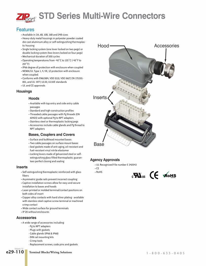
Features• Available in 3A, 6B, 10B, 16B and 24B sizes• Heavy-duty metal housings in polyester powder coated
die-cast aluminum alloy or self-extinguishing thermoplas-tic housing
• Single locking system (one lever locked on two pegs) ordouble locking system (two levers locked on four pegs)
• Mechanical duration of 500 cycles• Operating temperatures from -40°C to 125°C (-40°F to
257°F)• IP66 degree of protection with enclosure when coupled• NEMA/UL Type 1, 4, 4X, 12 protection with enclosure
when coupled.• Conforms with EN61984, VDE 0110, VDE 0627, EN 175301-
801, and UL 1977, UL50, UL50E standards• UL and CE approvals
Housings
Hoods• Available with top entry and side entry cable
passages• Standard and high-construction profiles• Threaded cable passages with Pg threads (EN
60423) with optional Pg to NPT adapters• Stainless steel or thermoplastic locking pegs• Accessories include cable glands and Pg thread to
NPT adapters
Bases, Couplers and Covers• Surface and bulkhead mounted bases• Two cable passages on surface mount bases• Seal gaskets made of anti-aging, oil-resistant and
fuel-resistant vinyl nitrile elastomer• Locking levers made of galvanized steel or self-
extinguishing glass-filled thermoplastic; guaran-tees perfect closing and sealing
Inserts• Self-extinguishing thermoplastic reinforced with glass
fibers• Asymmetric guide rails prevent incorrect coupling• Captive installation screws allow for easy and secure
installation to bases and hoods• Laser-printed or molded terminal/contact positions on
both sides of insert• Copper alloy contacts with hard silver plating - available
with stainless steel captive screw terminal or machinedcrimp contact
• Wide contact surface for ground terminals• IP 20 without enclosures
Accessories• A wide range of accessories including:
- Pg to NPT adapters- Plugs with gaskets- Cable glands (IP66 & IP68)- DIN rail mounting kits- Crimp tools- Replacement screws, code pins and gaskets
STD Series Multi-Wire Connectors
Hood
Inserts
Base
Accessories
Agency Approvals • UL Recognized File number E 342543• CE• RoHS

CompanyInformation
SystemsOverview
ProgrammableControllers
Field I/O
Software
C-more & other HMI
Drives
SoftStarters
Motors &Gearbox
Steppers/Servos
Motor Controls
ProximitySensors
Photo Sensors
Limit Switches
Encoders
CurrentSensors
PressureSensors
TemperatureSensors
Pushbuttons/Lights
Process
Relays/Timers
Comm.
TerminalBlocks & Wiring
Power
CircuitProtection
Enclosures
Tools
Pneumatics
Appendix
ProductIndex
Part #Index
Terminal Blocks/Wiring Solutionswww.automat iond i rec t . com/wi r ing- so lu t ions e29-111Volume 13
Size and Identification
The size of each type of connector is determined by thedistance between the center points of the four installationscrews. These four points are common to both the insert andthe housing. This is indicated by “X”-“Y” in the illustrationabove.
The table below lists the size identification and the actual X-Ydistance for each type of connector offered.
YX
Size DistanceX-Y
3A (21 x 21 mm)* (0.83 x 0.83 in)
6B 44 x 27 mm (1.73 x 1.06 in)
10B 57 x 27 mm (2.24 x 1.06 in)
16B 77.5 x 27 mm (3.05 x 1.06 in)
24B 104 x 27 mm (4.09 x 1.06 in)
* The center distance cannot be given because the 3A inserts have only onescrew: 21 x 21 indicates the size of the sectioned insert.
STD Series Multi-Wire Connectors
Size 24B shown
General CharacteristicsApplication Examples
• Electronic machinery• Robots• Control equipment• Power connections• Control and signal circuits• Packaging machinery• Theatrical applications• Industrial equipment• Electrical panels
Inserts
ZIPport multi-wire connectors require one male and one femaleinsert. The inserts are available in multiple pole configurationsfrom 3 poles plus ground up to 108 poles plus ground and withtermination sizes ranging from 14 to 5 AWG, 10 to 80 Amps.
ZIPport inserts are made of UL 94 V-0 rated self-extinguishing thermoplastic resin rated at a maximum temperature of 125°C(257°F). The inserts are available in screw terminal and crimpstyle contact block connections. The contacts are copper alloywith a hard silver plating. The plastic insulators are numbered onboth sides by laser printing or molding in accordance with EN 60068-2-70.
• Suitable for use with alternating (AC) or direct current (DC)• Leading protective ground• Polarized for correct mating• Interchangeable for male and female inserts in hoods and bases• Captive screws• Can be used with hoods and bases, or with rack and panel
applications
HousingsThe housings for the ZIPport multi-wire connectors consist of ahood that mates with a base or a coupler.
They are made of die-cast aluminum with a polyester powderfinish or from self-extinguishing thermoplastic and are suitable foruse in industrial applications.
All housings are available in a standard profile. Several areoffered with a high construction (HC) profile that allows moreroom for wiring the higher density inserts.
A single or double lever locking system assures coupling stabilityand protection against accidental opening. The locking system iscomprised of stainless steel or glass filled thermoplastic levers,with compatible interlocking pegs.
Terminal Blocks/Wiring Solutions 1 - 8 0 0 - 6 3 3 - 0 4 0 5e29-118Volume 13
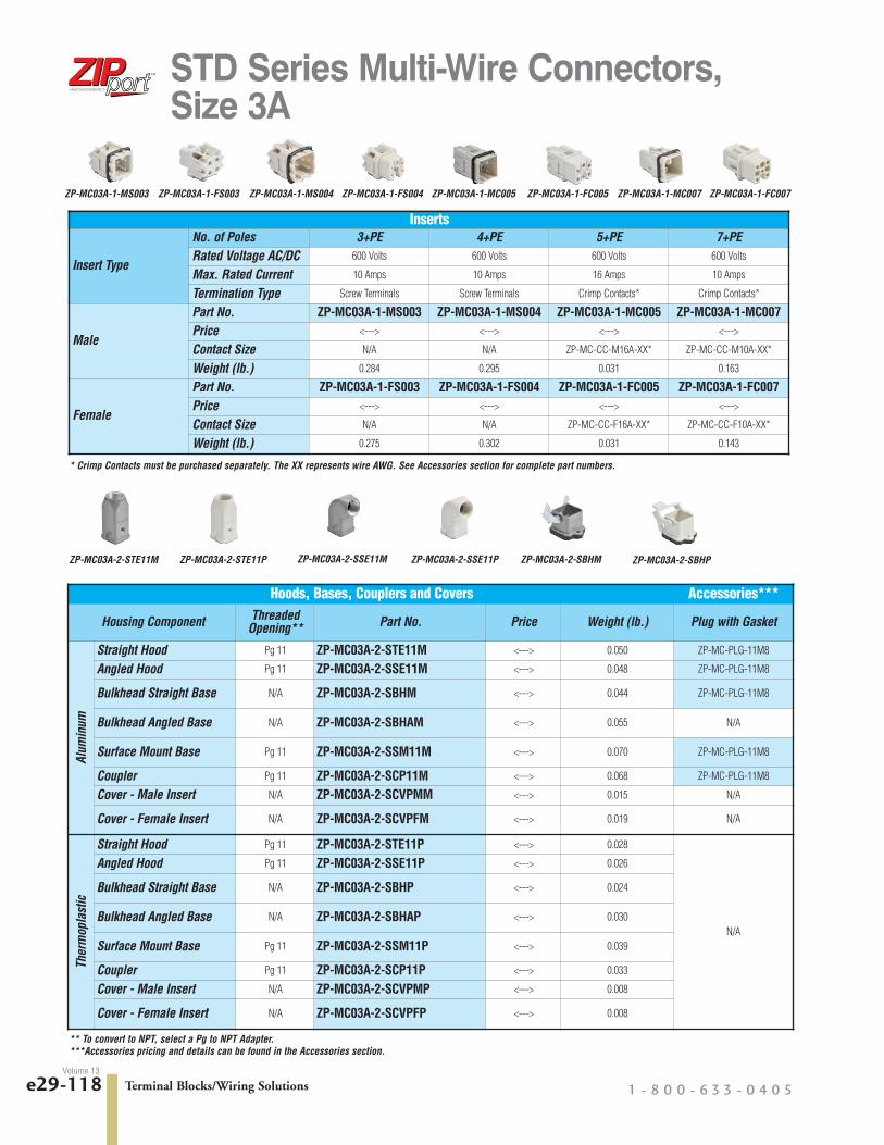
STD Series Multi-Wire Connectors,Size 3A
Inserts
Insert Type
No. of Poles 3+PE 4+PE 5+PE 7+PERated Voltage AC/DC 600 Volts 600 Volts 600 Volts 600 Volts
Max. Rated Current 10 Amps 10 Amps 16 Amps 10 Amps
Termination Type Screw Terminals Screw Terminals Crimp Contacts* Crimp Contacts*
Male
Part No. ZP-MC03A-1-MS003 ZP-MC03A-1-MS004 ZP-MC03A-1-MC005 ZP-MC03A-1-MC007Price <---> <---> <---> <--->
Contact Size N/A N/A ZP-MC-CC-M16A-XX* ZP-MC-CC-M10A-XX*
Weight (lb.) 0.284 0.295 0.031 0.163
Female
Part No. ZP-MC03A-1-FS003 ZP-MC03A-1-FS004 ZP-MC03A-1-FC005 ZP-MC03A-1-FC007Price <---> <---> <---> <--->
Contact Size N/A N/A ZP-MC-CC-F16A-XX* ZP-MC-CC-F10A-XX*
Weight (lb.) 0.275 0.302 0.031 0.143
Hoods, Bases, Couplers and Covers Accessories***
Housing Component ThreadedOpening** Part No. Price Weight (lb.) Plug with Gasket
Alum
inum
Straight Hood Pg 11 ZP-MC03A-2-STE11M <---> 0.050 ZP-MC-PLG-11M8
Angled Hood Pg 11 ZP-MC03A-2-SSE11M <---> 0.048 ZP-MC-PLG-11M8
Bulkhead Straight Base N/A ZP-MC03A-2-SBHM <---> 0.044 ZP-MC-PLG-11M8
Bulkhead Angled Base N/A ZP-MC03A-2-SBHAM <---> 0.055 N/A
Surface Mount Base Pg 11 ZP-MC03A-2-SSM11M <---> 0.070 ZP-MC-PLG-11M8
Coupler Pg 11 ZP-MC03A-2-SCP11M <---> 0.068 ZP-MC-PLG-11M8
Cover - Male Insert N/A ZP-MC03A-2-SCVPMM <---> 0.015 N/A
Cover - Female Insert N/A ZP-MC03A-2-SCVPFM <---> 0.019 N/A
Ther
mop
last
ic
Straight Hood Pg 11 ZP-MC03A-2-STE11P <---> 0.028
N/A
Angled Hood Pg 11 ZP-MC03A-2-SSE11P <---> 0.026
Bulkhead Straight Base N/A ZP-MC03A-2-SBHP <---> 0.024
Bulkhead Angled Base N/A ZP-MC03A-2-SBHAP <---> 0.030
Surface Mount Base Pg 11 ZP-MC03A-2-SSM11P <---> 0.039
Coupler Pg 11 ZP-MC03A-2-SCP11P <---> 0.033
Cover - Male Insert N/A ZP-MC03A-2-SCVPMP <---> 0.008
Cover - Female Insert N/A ZP-MC03A-2-SCVPFP <---> 0.008
* Crimp Contacts must be purchased separately. The XX represents wire AWG. See Accessories section for complete part numbers.
** To convert to NPT, select a Pg to NPT Adapter.***Accessories pricing and details can be found in the Accessories section.
ZP-MC03A-2-STE11M ZP-MC03A-2-STE11P ZP-MC03A-2-SSE11M ZP-MC03A-2-SSE11P ZP-MC03A-2-SBHM ZP-MC03A-2-SBHP
ZP-MC03A-1-MS003 ZP-MC03A-1-FC007ZP-MC03A-1-FS003 ZP-MC03A-1-MS004 ZP-MC03A-1-FS004 ZP-MC03A-1-MC005 ZP-MC03A-1-FC005 ZP-MC03A-1-MC007

CompanyInformation
SystemsOverview
ProgrammableControllers
Field I/O
Software
C-more & other HMI
Drives
SoftStarters
Motors &Gearbox
Steppers/Servos
Motor Controls
ProximitySensors
Photo Sensors
Limit Switches
Encoders
CurrentSensors
PressureSensors
TemperatureSensors
Pushbuttons/Lights
Process
Relays/Timers
Comm.
TerminalBlocks & Wiring
Power
CircuitProtection
Enclosures
Tools
Pneumatics
Appendix
ProductIndex
Part #Index
Terminal Blocks/Wiring Solutionswww.automat iond i rec t . com/wi r ing- so lu t ions e29-119Volume 13
STD Series Multi-Wire Connectors,Size 3A
Accessories*** Continued
Housing Component IP66 Cable Glands IP68 Cable GlandsPg to NPT Adapter
Pg 11 to 3/8” Pg 11 to 1/2”
Alum
inum
Straight Hood ZP-MC-CG-11M5 ZP-MC-CG-11M8 ZP-MC-A-11038 ZP-MC-A-11012
Angled Hood ZP-MC-CG-11M5 ZP-MC-CG-11M8 ZP-MC-A-11038 ZP-MC-A-11012
Bulkhead Straight Base ZP-MC-CG-11M5 ZP-MC-CG-11M8 ZP-MC-A-11038 ZP-MC-A-11012
Bulkhead Angled Base N/A N/A N/A N/A
Surface Mount Base ZP-MC-CG-11M5 ZP-MC-CG-11M8 ZP-MC-A-11038 ZP-MC-A-11012
Coupler ZP-MC-CG-11M5 ZP-MC-CG-11M8 ZP-MC-A-11038 ZP-MC-A-11012
Cover - Male Insert N/A N/A N/A N/A
Cover - Female Insert N/A N/A N/A N/A
Ther
mop
last
ic
Straight Hood ZP-MC-CG-11P5 N/A N/A N/A
Angled Hood ZP-MC-CG-11P5 N/A N/A N/A
Bulkhead Straight Base ZP-MC-CG-11P5 N/A N/A N/A
Bulkhead Angled Base N/A N/A N/A N/A
Surface Mount Base ZP-MC-CG-11P5 N/A N/A N/A
Coupler ZP-MC-CG-11P5 N/A N/A N/A
Cover - Male Insert N/A N/A N/A N/A
Cover - Female Insert N/A N/A N/A N/A
*** Accessories pricing and details can be found in the Accessories section.
ZP-MC03A-2-SBHAM ZP-MC03A-2-SBHAP ZP-MC03A-2-SSM11M ZP-MC03A-2-SSM11P ZP-MC03A-2-SCP11M ZP-MC03A-2-SCP11P
ZP-MC03A-2-SCVPMM ZP-MC03A-2-SCVPMP ZP-MC03A-2-SCVPFM ZP-MC03A-2-SCVPFP
Plug with GasketIP66 Cable Gland IP68 Cable Gland PG to NPT Adapter

Terminal Blocks/Wiring Solutions 1 - 8 0 0 - 6 3 3 - 0 4 0 5e29-128Volume 13
STD Series Multi-Wire ConnectorsElectrical Engineering Data - Load Diagrams
Size 3A 3P +
Con
tinuo
us c
urre
nt (A
)
Ambient temperature (C°)
32
28
24
20
16
12
8
4
0
20 30 40 50 60 70 80 90 100 110 120 130
1,0 mm²
1,5 mm²
2,5 mm²
Size 3A 4P +
Con
tinuo
us c
urre
nt (A
)
Ambient temperature (C°)
32
28
24
20
16
12
8
4
0
20 30 40 50 60 70 80 90 100 110 120 130
1,0 mm²
1,5 mm²
2,5 mm²
Size 3A 7P +
Con
tinuo
us c
urre
nt (A
)
Ambient temperature (C°)
16
14
12
10
8
6
4
2
0
20 30 40 50 60 70 80 90 100 110 120 130
1,0 mm²
1,5 mm²
2,5 mm²
Con
tinuo
us c
urre
nt (A
)
Ambient temperature (C°)
32
28
24
20
16
12
8
4
0
20 30 40 50 60 70 80 90 100 110 120 130
0,5 mm²
1,0 mm²
1,5 mm²
2,5 mm²
Size 3A 5P +
Derating diagram According to IEC/EN 60512These diagrams illustrate the maximum current carrying capacity of components. The illustration follows a curvewhich shows the current in relation to ambient temperature.
Current carrying capacity is limited by the thermal characteristics of contacts and insulating elements which havean upper temperature limit that should not be exceeded.

Terminal Blocks/Wiring Solutions 1 - 8 0 0 - 6 3 3 - 0 4 0 5e29-136Volume 13
STD Series Multi-Wire Dimensions
Size 3A Inserts
Male MaleFemale Female
Male MaleFemale Female
3 + PE - Screw Terminals 4 + PE - Screw Terminals
5 + PE - Crimp Contacts 7 + PE - Crimp Contacts
ZP-MC03A-1-MS003 ZP-MC03A-1-FS003 ZP-MC03A-1-MS004 ZP-MC03A-1-FS004
ZP-MC03A-1-MC005 ZP-MC03A-1-FC005 ZP-MC03A-1-MC007 ZP-MC03A-1-FC007
Dimensions mm [in]

CompanyInformation
SystemsOverview
ProgrammableControllers
Field I/O
Software
C-more & other HMI
Drives
SoftStarters
Motors &Gearbox
Steppers/Servos
Motor Controls
ProximitySensors
Photo Sensors
Limit Switches
Encoders
CurrentSensors
PressureSensors
TemperatureSensors
Pushbuttons/Lights
Process
Relays/Timers
Comm.
TerminalBlocks & Wiring
Power
CircuitProtection
Enclosures
Tools
Pneumatics
Appendix
ProductIndex
Part #Index
Terminal Blocks/Wiring Solutionswww.automat iond i rec t . com/wi r ing- so lu t ions e29-137Volume 13
STD Series Multi-Wire DimensionsSize 3A Housings
Straight Hood Angled Hood
Bulkhead Straight Base Bulkhead Angled Base Surface Mount Base
Coupler Cover
Note: Includes attached 112 mm [4.40 inch]nylon cord with ring terminal
ZP-MC03A-2-STE11M/P ZP-MC03A-2-SSE11M/P
ZP-MC03A-2-SBHM/P ZP-MC03A-2-SBHAM/P ZP-MC03A-2-SSM11M/P
ZP-MC03A-2-SCP11M/P
ZP-MC03A-2-SCVPMM/PZP-MC03A-2-SCVPFM/P
Dimensions mm [in]

Terminal Blocks/Wiring Solutions 1 - 8 0 0 - 6 3 3 - 0 4 0 5e29-112Volume 13
STD Series Multi-Wire Connectors
Conductor TerminationOverviewTwo types of conductor termination are available for ZIPportinserts:
• Screw terminations• Crimp terminations
Screw TerminationsScrew terminations consist of contacts made of silver-platedcopper alloy and are incorporated with a wire clamp (with theexception of the size 3A inserts and size 24B with 80A contacts)for firmly securing the conductors. The screw terminals use stain-less steel captive screws and meet VDE 0609 / EN 60999 stan-dards.
Proper conductor installation requires no special preparationwhen using inserts with the wire clamp terminals. The table belowlists the current rating, maximum wire gauge and strippinglengths.
The value of tensile strength of conductors in accordance withthe dimensions of the screws and the wires are shown in thefollowing table:
Increasing the tightening torque does not necessarily improve thecontact resistance. The screw torques are selected according tostandard EN 60999-1, to provide excellent mechanical, thermaland electrical behaviour. The conductor or terminal may bedamaged if the recommended values are significantly exceeded.
Crimp TerminationsCrimp terminations consist of contacts made of silver-platedcopper alloy. Crimp terminations are accomplished by applyinga crimp contact to the conductor by means of a crimping tool.Crimp contacts are available in several sizes:
10 amp, 22-14 AWG
16 amp, 22-12 AWG
A perfect crimp connection is gastight, corrosion free and isequal to a cold weld of the parts being connected. Wires to beconnected must be carefully matched with the correct wire sizeof crimp contacts.
The requirements for crimp connectors are depicted in IEC60352, part 2.
Note: Low currents and voltages:
ZIPport standard contacts (screw and crimp) have a silverplated surface. This metal has excellent conductive properties.During the contacts’s lifetime, the silver surface generates ablack oxide layer due to its affinity to sulphur (always present inthe atmosphere). This layer is conductive smooth and very thinand is partly interrupted when the contacts are mated andunmated, thus guaranteeing very low contact resistances. In thecase of very low current or voltage, small changes to the trans-mitted signal may be encountered.
In applications where voltage and current are lower than 5Vand 5mA, and in extremely aggressive environments, goldplated contacts are recommended. Gold plated contacts arenot currently sold by AutomationDirect.com.
Current RatingMax Wire Gauge Stripping Length
mm (in)(mm ²) AWG10A 2.5 14 4.5 (0.18)
16A 2.5 14 7 (0.28)
35A 6.0 10 11.5 (0.45)
16/80A 25/16 14/5 7 (0.28)/14 (0.55)
Wire Clamp
Screw Terminals with Wire Clamps
Wire Gauge mm² (AWG)
1.5(16)
2.5(14)
4(12)
6(10)
10(8)
16(6)
Size of Screw M3 M3 M3.5 M4 M4 M6
Tensile Strength ofStranded Wire (N) 40 50 60 80 90 100
Insert Screw Specifications
InsertSize Screw Type
Scre
w S
ize
Tigh
teni
ng T
orqu
e(N
m)
Tigh
teni
ng T
orqu
e(in
-lbs)
Reco
mm
ende
dSc
rew
driv
er S
ize
Reco
mm
ende
dSc
rew
driv
er P
art
3A
16 Amp TerminalM3
0.25 2.2 0.4 x 2.5 DN-SS310 Amp Terminal
InstallationGround M3.5
6B,10B
16 Amp TerminalM3 0.50 0.44 Ph 0-0.8 x 4 DN-SS4
InstallationGround M4 1.2 10.6 Ph 2 1.0 x 5.5 DN-SS5
16B
35 Amp Terminal M4 1.2 10.6 Ph 1 - 0.8 x 4DN-SS416 Amp Terminal
M3 0.50 0.44 Ph 0-0.8 x 4Installation
Ground M4 1.2 10.6 Ph 2 1.0 x 5.5DN-SS5
24B
80 Amp Terminal M6 2.5 22.1 1.0 x 5.516 Amp Terminal
M3 0.50 0.44 Ph 0-0.8 x 4 DN-SS4Installation
Ground M4 1.2 10.6 Ph 2 1.0 x 5.5 DN-SS5

CompanyInformation
SystemsOverview
ProgrammableControllers
Field I/O
Software
C-more & other HMI
Drives
SoftStarters
Motors &Gearbox
Steppers/Servos
Motor Controls
ProximitySensors
Photo Sensors
Limit Switches
Encoders
CurrentSensors
PressureSensors
TemperatureSensors
Pushbuttons/Lights
Process
Relays/Timers
Comm.
TerminalBlocks & Wiring
Power
CircuitProtection
Enclosures
Tools
Pneumatics
Appendix
ProductIndex
Part #Index
Terminal Blocks/Wiring Solutionswww.automat iond i rec t . com/wi r ing- so lu t ions e29-113Volume 13
STD Series Multi-Wire ConnectorsCrimp Contact to Insert InstallationProper installation of the crimp contacts is important for a good electrical and mechanical connection. The following steps willensure correct installation.
Step 1: Select the Crimp Contacts Select a crimp contact based on the rating of the Insert you are using - 10 or 16 amps; the gender - male or female; and gaugeof wire being used.
Step 2:
Step 3: Install the Insert into the Housing.Now that the crimp contacts are installed, the insert can be placed into the housing by aligning the corner installation screws of theinsert with the screw holes located in the corners of the housing. Tighten the screws according to the tightening torques listed in theInsert Screw Specifications table in this document.
Metric/PgConnection
Adapter toNPT Pipe Fitting
IP68Cable Gland
IP66 Cable Glandwith washer
Wire Entry ConnectionZIPports offer four types of connection for wire entry into the housings. Two entries accommodate flex conduit and two accept cable.
CLICK!CLICK!
Install the Crimp Contacts Into the InsertInstall the Crimp Contacts Into the InsertInstall the Crimp Contacts Into the InsertInstall the Crimp Contacts Into the InsertInstall the Crimp Contacts Into the InsertA Insert stripped
wire end into contact.
B Use Crimping Tool to secure connection.
C Thread wire and crimped contact through appropriate hood, base, or coupler.
D Slide crimped contact into insert until “click” indicates that contact is secure.
This is standard on all hous-ings that offer a threadedwire entry. Sizes range fromPg 11 to Pg 29. This is forusing fittings with a male Pgthread connection.
This adapter converts the Pgthread to an NPT thread.Sizes range from 3/8” to 1-1/4” in relation to the Pgthreaded opening in thehousing.
For securing a cable to thehousing. This is an all inclu-sive fitting that can be tight-ened without using separatewashers.
For securing a cable to thehousing. This gland is avail-able in plastic or metal inrelation to housing material.Includes two washers andfour gaskets to accomodatea wide range of cable diam-eters.

Terminal Blocks/Wiring Solutions 1 - 8 0 0 - 6 3 3 - 0 4 0 5e29-114Volume 13
StandardsThe inserts are designed and manufactured to conform with EN 61984, (IEC 61984), VDE 0627 and UL 1977/CSA C22.2182.3 standards. They are certified and labeled with the cULusand CE marks. The connectors are therefore in conformance withboth European/International and American systems. This permitsthem to be used in a wider range of applications worldwide.
• EN 61984 Connectors safety requirements andtests
• VDE 0627 Connectors (DIN VDE 0627)
• EN 60664-1 Insulation coordination for equipmentwithin low-voltage systems
• EN 175 301-801 High density rectangular connectors,round removable crimp contacts
• EN 60947-7-1 part 7-1 Low-voltage switchgear and controlgear, Ancillary equipment - Terminalblocks for copper conductors
• VDE 0110 Table 4 concerning clearance and creepage distances
• EN 60512 Connectors for electronic equipment,tests and measurements
• UL 1977 Component connectors for use in data,signal, control and power applications
• CSA.C22.2 No. 182.3 Special use attachment, plugs, receptacles and connectors
• EN 60529 Degree of protection provided by enclosures (IP degree)
• EN 50262 Metric cable glands for electrical installation
• EN 60423 Conduits for electrical purposes.Outside diameters of conduits for electrical installations and thread forconduits and fittings
• ISO 23570-2 Industrial automation system and integration. Distributed installation inindustrial applications. Part 2: Hybridcommunication bus.
• ISO 23570-3 Industrial automation system and integration. Distributed installation inindustrial applications Part 3: Power distribution bus.
DESINA® specifications Specification to standardize electrical, hydraulic and pneumaticcomponents and their interconnectionon a common platform for CNC controlled machine tools and manufacturing lines.
Directives and DeclarationsNEMA-250 Declaration of Conformity
Metal and plastic enclosures for Multipole Industrial Connectors(Heavy Duty Connectors). Series STD, STD-HV, HE, HE-HV allsizes. Are designed and manufactured in conformity with NEMA250-1991 Standard and meet the requirements of NEMA Type 4,4x and 12.
2006/95/EC: LVD Directive
Directive 2006/95/EC of the European Parliament and of thecouncil of 12 December 2006 on the harmonisation of the lawsof Members States relating to electrical equipment designed foruse within certain voltage limits.
2002/95/EC: RoHS Directive
Directive 2002/95/EC of the European Parliament and of theCouncil of 27 January 2003 on the restriction of the use ofcertain hazardous substances in electrical and electronic equipment.
2008/35/EC: RoHS Directive amendment
Directive 2008/35/EC of the European Parliament and of theCouncil of 11 March 2008 amending Directive 2002/95/EC ofthe use of certain hazardous substances in electrical and electronic equipments (RoHS) as regards the implementingpowers conferred on the Commission.
2004/108/EC EMC Directive
EMC, Electromagnetic Compatibility Directive.
In accordance with the European Directive that regulates theemission and the immunity of the equipment, for the productsdesigned for EMC industrial applications.
Regulation (EC) No 1907/2006 of the European Parliament andof the Council of 18 December 2006 concerning the RegistrationEvaluation, Authorization and Restriction of Chemicals (REACH),establishing a European Chemicals Agency, amending Directive1999/45/EC and repealing Council Regulation (EEC) No793/93 and Commission Regulation (EC) No 1488/94 as wellas Council Directive 76/769/EEC and Commission Directives91/155/EEC, 93/67/EEC, 93/105/EEC and 2000/21/EC.
Warning - According to EN 61984, connectors should not be coupled and decoupled under electical load.
Type 1/4/4x/12
Standard Series Multi-Wire Connectors
(Distributed and StandardizedInstallation Technology), Studiedby German Manufacturers ofMachine Tool Association.

CompanyInformation
SystemsOverview
ProgrammableControllers
Field I/O
Software
C-more & other HMI
Drives
SoftStarters
Motors &Gearbox
Steppers/Servos
Motor Controls
ProximitySensors
Photo Sensors
Limit Switches
Encoders
CurrentSensors
PressureSensors
TemperatureSensors
Pushbuttons/Lights
Process
Relays/Timers
Comm.
TerminalBlocks & Wiring
Power
CircuitProtection
Enclosures
Tools
Pneumatics
Appendix
ProductIndex
Part #Index
Terminal Blocks/Wiring Solutionswww.automat iond i rec t . com/wi r ing- so lu t ions e29-115Volume 13
STD Series Multi-Wire Connectors
Crimp Contact Basic Assembly Screw Terminal Basic Assembly
Strain Relief(Cable Gland)
Housing (Size 3ACoupler or Base)
Crimp Contacts(Female Contact)
Female Insert(Crimp Type)
Male Insert(Crimp Type)
Crimp Contacts(Male Contact)
Housing(Size 3A Hood)
Strain Relief(Cable Gland)
Strain Relief (Cable Gland)
Housing(Size 10B Hood)
Female Insert(Screw Type)
Male Insert(Screw Type)
Housing(Size 10B Surface Mount)
Strain Relief(Cable Gland)
Plug and Gasket
Pg to NPT Adapter or

Terminal Blocks/Wiring Solutions 1 - 8 0 0 - 6 3 3 - 0 4 0 5e29-132Volume 13
STD Series Multi-Wire ConnectorsSpare Parts and Accessories
Male Crimp Contact
Female Crimp Contact
Crimp Contacts - 10 Amp and 16 AmpCrimp contacts are made of hard-silver plated copper alloy. Wires to be connected must becarefully matched with the correct wire size of crimp contacts. Crimp contacts should beinstalled using a crimping tool.
Male Crimp Contact
Female Crimp Contact
Crimp Contact Tools
Part Number Qty. Description Price Weight(lb.)
ZP-MC-CT1
1
Crimping tool with dieset and locator <---> 1.593
ZP-MC-CT2 Crimping tool with dieset only, no locator <---> 0.814
ZP-MC-RT1 Removal tool for 10A contacts <---> 0.081
ZP-MC-RT2 Removal tool for 16A contacts <---> 0.086
ZP-MC-RT1 ZP-MC-RT2
ZP-MC-CT1
ZP-MC-CT2
10 Amp Crimp Contacts
Part Number Qty. Type(Male/Female)
Wire Gaugemm ² (AWG)
StrippingLength Price Weight
(lb.)ZP-MC-CC-M10A-22
100 per pack
Male
0.14-0.37 (26-22)
8 mm (0.32 in)
<---> 0.150
ZP-MC-CC-M10A-20 0.5 (20) <---> 0.150
ZP-MC-CC-M10A-18 0.75 (18) <---> 0.150
ZP-MC-CC-M10A-16 1.5 (16) <---> 0.150
ZP-MC-CC-M10A-14 2.5 (14) <---> 0.140
ZP-MC-CC-F10A-22
Female
0.14-0.37 (26-22) <---> 0.150
ZP-MC-CC-F10A-20 0.5 (20) <---> 0.140
ZP-MC-CC-F10A-18 0.75 (18) <---> 0.150
ZP-MC-CC-F10A-16 1.5 (16) <---> 0.140
ZP-MC-CC-F10A-14 2.5 (14) <---> 0.150
16 Amp Crimp Contacts
Part Number Qty. Type(Male/Female)
Wire Gauge mm ²(AWG)
StrippingLength Price Weight
(lb.)ZP-MC-CC-M16A-22
100 per pack
Male
0.14-0.37 (26-22)
7.5 mm (0.29 in)
<---> 0.280
ZP-MC-CC-M16A-20 0.5 (20) <---> 0.360
ZP-MC-CC-M16A-18 0.75 (18) <---> 0.270
ZP-MC-CC-M16A-16 1.5 (16) <---> 0.350
ZP-MC-CC-M16A-14 2.5 (14) <---> 0.270
ZP-MC-CC-M16A-12 4.0 (12) <---> 0.350
ZP-MC-CC-F16A-22
Female
0.14-0.37 (26-22) <---> 0.280
ZP-MC-CC-F16A-20 0.5 (20) <---> 0.350
ZP-MC-CC-F16A-18 0.75 (18) <---> 0.290
ZP-MC-CC-F16A-16 1.5 (16) <---> 0.350
ZP-MC-CC-F16A-14 2.5 (14) <---> 0.280
ZP-MC-CC-F16A-12 4.0 (12) <---> 0.350
Note: The crimp contact ampacity listed above is the Maximum current rating for the crimp contacts only. The current ratingDOES NOT reflect the wire gauge current rating.
Note: The crimp contact ampacity listed above is the Maximum current rating for the crimp contacts only. The current ratingDOES NOT reflect the wire gauge current rating.

CompanyInformation
SystemsOverview
ProgrammableControllers
Field I/O
Software
C-more & other HMI
Drives
SoftStarters
Motors &Gearbox
Steppers/Servos
Motor Controls
ProximitySensors
Photo Sensors
Limit Switches
Encoders
CurrentSensors
PressureSensors
TemperatureSensors
Pushbuttons/Lights
Process
Relays/Timers
Comm.
TerminalBlocks & Wiring
Power
CircuitProtection
Enclosures
Tools
Pneumatics
Appendix
ProductIndex
Part #Index
Terminal Blocks/Wiring Solutionswww.automat iond i rec t . com/wi r ing- so lu t ions e29-133Volume 13
Cable GlandsIP66 GlandsPlastic
• Thread: 1.5 mm pitch in accordance with EN 50262, Pg in accordance with DIN 40430
• IP Protection: IP66 in accordance with EN 60529• Working Temperature: -40°C to 125°C (-40°F to 257°F)• Materials: Body - Glass filled polyamide UL 94 V0; Washer - zinc
plated steel; Gasket - Elastomer• Includes two washers and four gaskets to accommodate a wide
range of cable diameters• Applications: for size 3A plastic type housings
Metal• Thread: 1.5 mm pitch in accordance with EN 50262, Pg in
accordance with DIN 40430• IP Protection: IP66 in accordance with EN 60529• Working Temperature: -40°C to 125°C (-40°F to 257°F)• Materials: Body - nickel-plated brass; Washer - zinc plated steel;
Gasket - Elastomer• Includes two washers and four gaskets to accommodate a wide
range of cable diameters• Applications: for all sizes metal type housings
IP68 GlandsMetal
• Thread: 1.5 mm pitch in accordance with EN 50262, Pg in accordance with DIN 40430
• IP Protection: IP68, patented design for up to 5 bars• Working Temperature: -40°C to 125°C (-40°F to 257°F)• Materials: Body - nickel-plated brass; Strain relief - Glass filled
polyamide UL 94 V0; Gasket - Elastomer• Applications: for industrial connector housings where higher
protection and strength are required
IP66 Cable Glands
Part Number Qty. Type Cable Diametermm (in) Thread Price Weight (lb.)
ZP-MC-CG-11P5
1
Plastic 7-12 (0.275-0.472) Pg 11 <---> 0.019
ZP-MC-CG-11M5
Metal
7-12 (0.275-0.472) Pg 11 <---> 0.030
ZP-MC-CG-16M5 7-14.5 (0.275-0.570) Pg 16 <---> 0.041
ZP-MC-CG-21M5 9.5-18.5 (0.374-0.728) Pg 21 <---> 0.070
ZP-MC-CG-29M5 17.5-26.5 (0.688-1.043) Pg 29 <---> 0.125
STD Series Multi-Wire ConnectorsSpare Parts and Accessories
IP68 Cable Glands
Part Number Qty. Type Thread Diametermm (in) Price Weight (lb.)
ZP-MC-CG-11M810 per pack
Metal
Pg 11 4-10 (0.157-0.393) <---> 0.451
ZP-MC-CG-16M8 Pg 16 8-14 (0.314-0.551) <---> 0.881
ZP-MC-CG-21M85 per pack
Pg 21 11-18 (0.433-0.708) <---> 0.727
ZP-MC-CG-29M8 Pg 29 16-25 (0.629-0.984) <---> 1.466
IP66 Cable Glands -Plastic
IP66 Cable Glands -Metal
IP68 Cable Glands
Note: IP66 cable glands with washers CANNOT be used with HC (High Construction) top or side entry housings.You must use the IP68 cable glands. IP66 glands can be used with surface mount HC (High Construction)housings.

Terminal Blocks/Wiring Solutions 1 - 8 0 0 - 6 3 3 - 0 4 0 5e29-134Volume 13
Blanking Plugs with Gasket
• Thread: 1.5 mm pitch in accordance with EN 50262, Pg in accordance with DIN 40430• IP Protection: IP68 in accordance with EN 60529• Working Temperature: -40°C to 125°C (-40°F to 257°F)• Materials: Body - nickel-plated brass; Gasket - Elastomer• Applications: for blanking threaded holes on housings or other enclosures
Blanking Plugs W/Gasket
Part Number Qty. Type Thread Price Weight (lb.)
ZP-MC-PLG-11M810 per pack
Metal
Pg 11 <---> 0.169
ZP-MC-PLG-16M8 Pg 16 <---> 0.253
ZP-MC-PLG-21M8 Pg 21 <---> 0.478
ZP-MC-PLG-29M8 5 per pack Pg 29 <---> 0.218
Pg to NPT Adapters
Part Number Qty. Type Pg Thread NPT Thread Price Weight (lb.)
ZP-MC-A-11038
1 Metal
Pg 11 3/8” <---> 0.044
ZP-MC-A-11012 Pg 11 1/2” <---> 0.072
ZP-MC-A-16012 Pg 16 1/2” <---> 0.070
ZP-MC-A-21034 Pg 21 3/4” <---> 0.101
ZP-MC-A-29100 Pg 29 1” <---> 0.194
ZP-MC-A-29114 Pg 29 1 1/4” <---> 0.238
STD Series Multi-Wire ConnectorsSpare Parts and Accessories
Pg to NPT Adapters
• Thread: Metric 1.5 mm pitch Pg in accordance with DIN 40430, NPT in accordance with USAS B2-1• IP Protection: dependant on coupling and other components• Working Temperature: -60°C to 200°C (-76°F to 392°F)• Materials: nickel-plated brass• Applications: for converting a Pg thread to an NPT thread
Blanking PlugsW/Gasket
Pg to NPT Adapters
Replacement Gaskets
Part Number Qty. Size Type Material Price Weight (lb.)
ZP-MC03A-GSK
10 per pack
3A
For bulkhead housings
Nitrile BotadieneRubber (NBR)
<---> 0.085
ZP-MC06B-GSK 6B <---> 0.097
ZP-MC10B-GSK 10B <---> 0.105
ZP-MC16B-GSK 16B <---> 0.127
ZP-MC24B-GSK 24B <---> 0.141
ReplacementGaskets
Replacement Gaskets

CompanyInformation
SystemsOverview
ProgrammableControllers
Field I/O
Software
C-more & other HMI
Drives
SoftStarters
Motors &Gearbox
Steppers/Servos
Motor Controls
ProximitySensors
Photo Sensors
Limit Switches
Encoders
CurrentSensors
PressureSensors
TemperatureSensors
Pushbuttons/Lights
Process
Relays/Timers
Comm.
TerminalBlocks & Wiring
Power
CircuitProtection
Enclosures
Tools
Pneumatics
Appendix
ProductIndex
Part #Index
Terminal Blocks/Wiring Solutionswww.automat iond i rec t . com/wi r ing- so lu t ions e29-135Volume 13
DIN Rail Mounting Kits
Part Number Qty. Description Price Weight (lb.)
ZP-MC06B-DKIT
1
For size 6B inserts <---> 0.374
ZP-MC10B-DKIT For size 10B inserts <---> 0.377
ZP-MC16B-DKIT For size 16B inserts <---> 0.385
ZP-MC24B-DKIT For size 24B inserts <---> 0.392
ZP-MC-RT3 Insert removal tool <---> 0.052
Replacement Screws/Code PinsPart Number Qty. Description Figure Price Weight (lb.)
ZP-MC-SCRWKIT 2 pieces ofeach part
M3.5 - PE screw for size 3A inserts 1
<---> 0.048
M4 - PE screw for size 6B insert, size 10B insert, size 16B insert(16+PE) and size 24B insert (24+PE) 2
M4 - PE screw for size 16B insert (6+PE) and size 24B insert(8+4+PE) 3
M3 - Installation screw for 3A inserts only 4
M3 - Installation screw for all inserts except 3A 5
Code pin, male* 6
Code pin, female* 7
STD Series Multi-Wire ConnectorsSpare Parts and Accessories
DIN Rail MountingKits
* Code pins are used in applications where there are identical connectors that could be coupled with the incorrect mate, potentiallycausing equipment damage or breakdown. Code pins replace the installation screws on the inserts. The following combinations ofcode pins allow for a selective number of couples.
DIN Rail Mounting Kits
Replacement Screws/Code Pins
ZP-MC-RT3
• For mounting inserts inside an enclosure• Fits 35 mm DIN rail
Figure 1 Figure 2
Figure 3 Figure 4 Figure 5 Figure 6 Figure 7
Coding Pin Configurations