Embed Size (px)
Citation preview

Status of the Muon Alignment System
Muon Alignment Group
Muon IBDecember 11th, 2012
2
Status of the Track-based AlignmentStatus of the Upgrade on the Hardware-based Barrel
Alignment Issue with the Hardware-based EndCap Alignment
Outline
Zoltán Szillási (ATOMKI) Muon IB, November 29th, 2011
3
CMS tracking alignment workflow1. Update Tracker geometry
recently released with 2012 A+B data
2. Update Muon Global Position Record (GPR) optimum position of Muon system based on reconstruction performance
3. Update Muon geometry with new Tracker and new GPR run track-based algorithm over 2012 A+B data
Muon Geometry was updated in November 2012• DT and CSC chambers aligned with respect to Tracker using track-
based algorithm with 2012 A+B collision data slight performance improvement in Barrel (DTs were already aligned with
tracks from 2011 collision data) significant performance improvement in Endcaps (this is first time
individual CSCs are fully aligned with tracks)
Muon IB Meeting, 11 December 2012
Overview
4
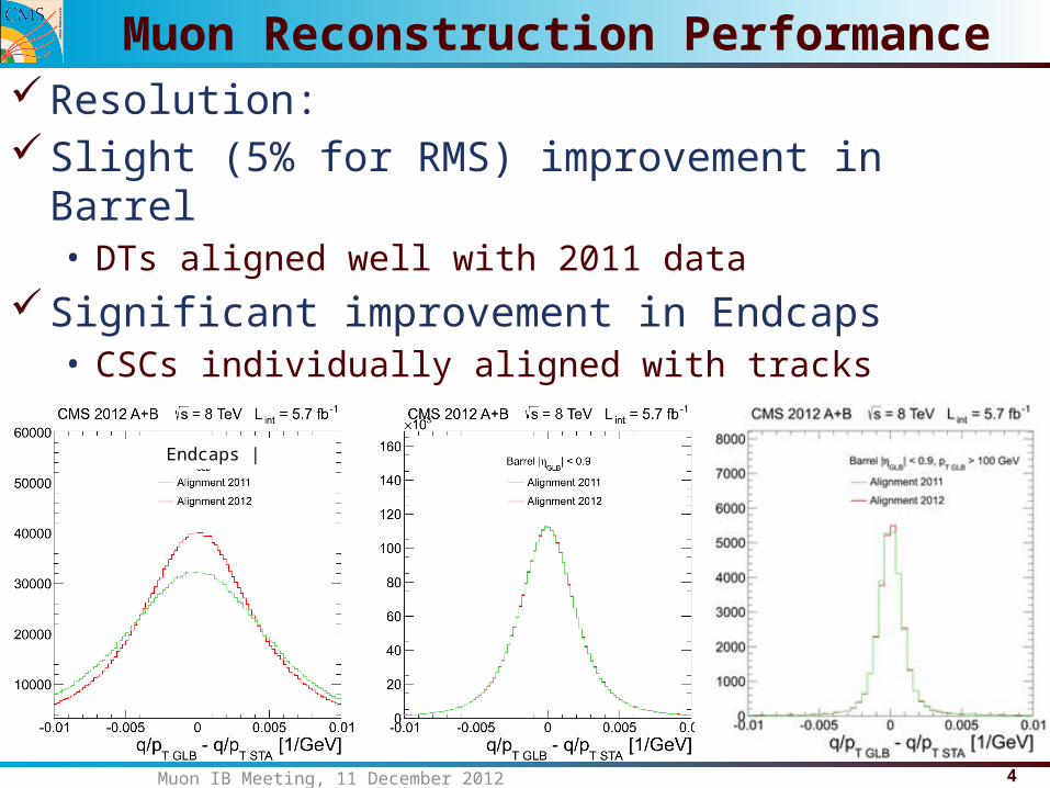
Resolution:Slight (5% for RMS) improvement in Barrel• DTs aligned well with 2011 data
Significant improvement in Endcaps• CSCs individually aligned with tracks
Muon IB Meeting, 11 December 2012
Muon Reconstruction Performance
Endcaps |
5
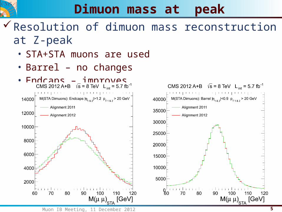
Resolution of dimuon mass reconstruction at Z-peak• STA+STA muons are used• Barrel – no changes• Endcaps – improves
Muon IB Meeting, 11 December 2012
Dimuon mass at peak
6
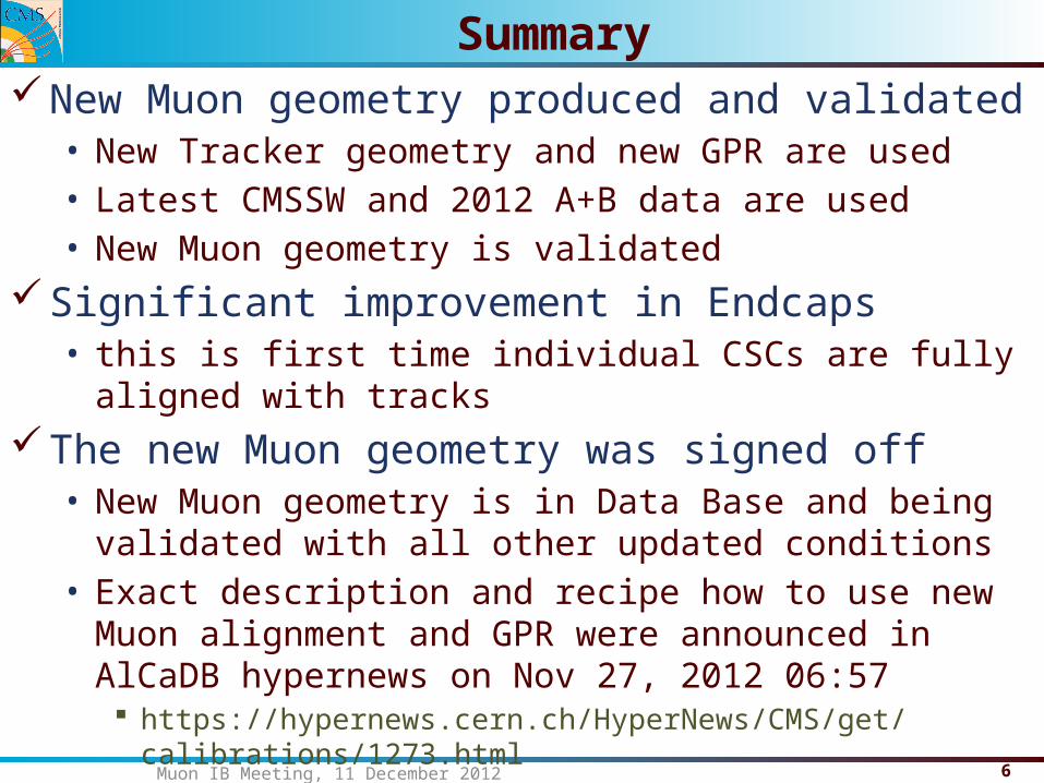
New Muon geometry produced and validated• New Tracker geometry and new GPR are used• Latest CMSSW and 2012 A+B data are used• New Muon geometry is validated
Significant improvement in Endcaps• this is first time individual CSCs are fully aligned with tracks
The new Muon geometry was signed off• New Muon geometry is in Data Base and being validated with all
other updated conditions• Exact description and recipe how to use new Muon alignment and
GPR were announced in AlCaDB hypernews on Nov 27, 2012 06:57 https://hypernews.cern.ch/HyperNews/CMS/get/calibrations/1273.html
Muon IB Meeting, 11 December 2012
Summary
7
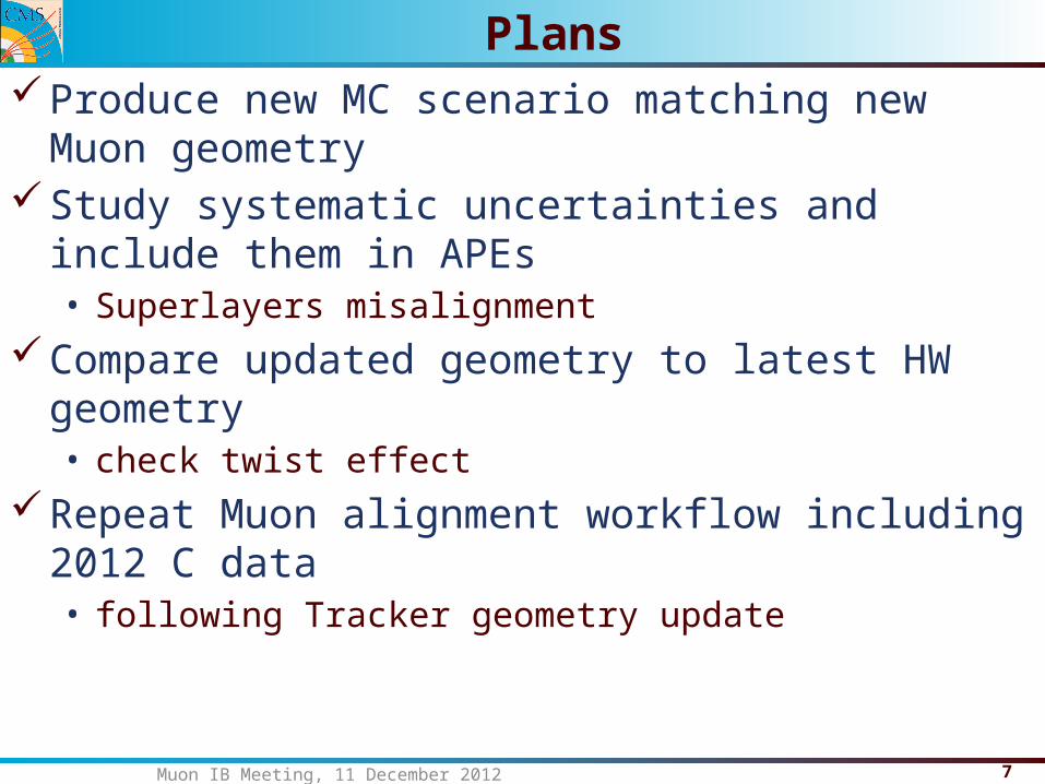
Produce new MC scenario matching new Muon geometryStudy systematic uncertainties and include them in APEs• Superlayers misalignment
Compare updated geometry to latest HW geometry• check twist effect
Repeat Muon alignment workflow including 2012 C data• following Tracker geometry update
Muon IB Meeting, 11 December 2012
Plans
8Zoltán Szillási (ATOMKI) Muon IB, November 29th, 2011
HW Barrel Ali Plans in LS1
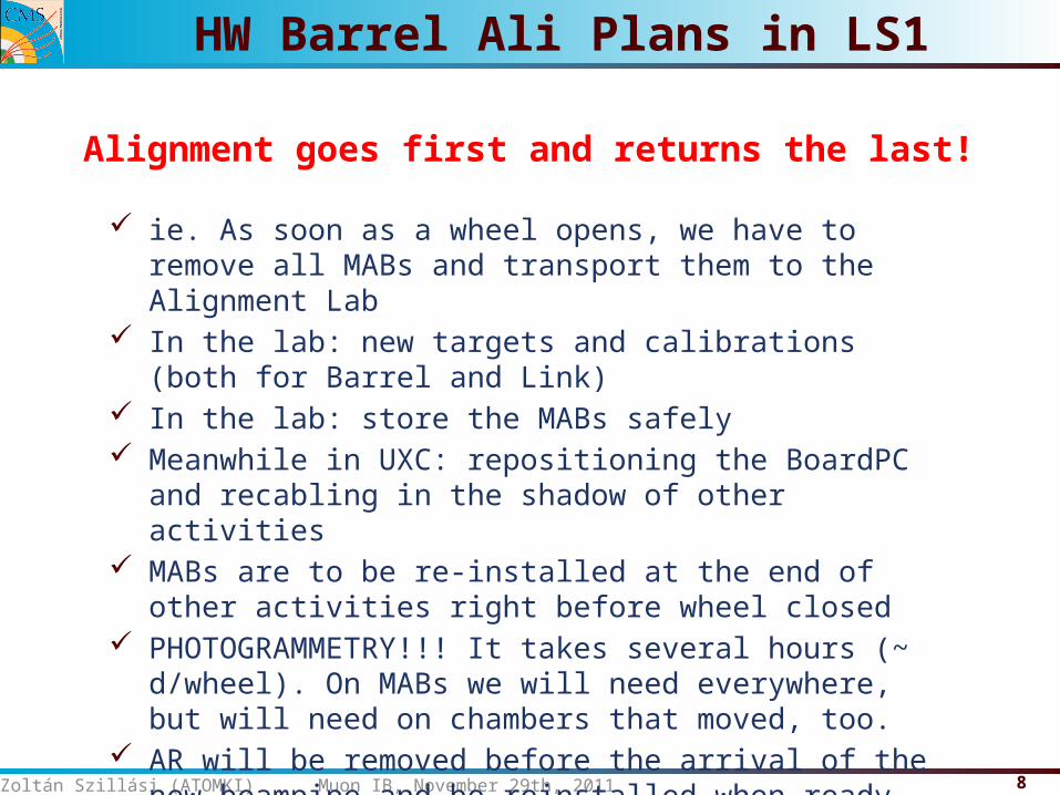
ie. As soon as a wheel opens, we have to remove all MABs and transport them to the Alignment Lab
In the lab: new targets and calibrations (both for Barrel and Link) In the lab: store the MABs safely Meanwhile in UXC: repositioning the BoardPC and recabling in the
shadow of other activities MABs are to be re-installed at the end of other activities right
before wheel closed PHOTOGRAMMETRY!!! It takes several hours (~ d/wheel). On
MABs we will need everywhere, but will need on chambers that moved, too.
AR will be removed before the arrival of the new beampipe and be reinstalled when ready – PG needed!
Alignment goes first and returns the last!
9Zoltán Szillási (ATOMKI) Muon IB, November 29th, 2011
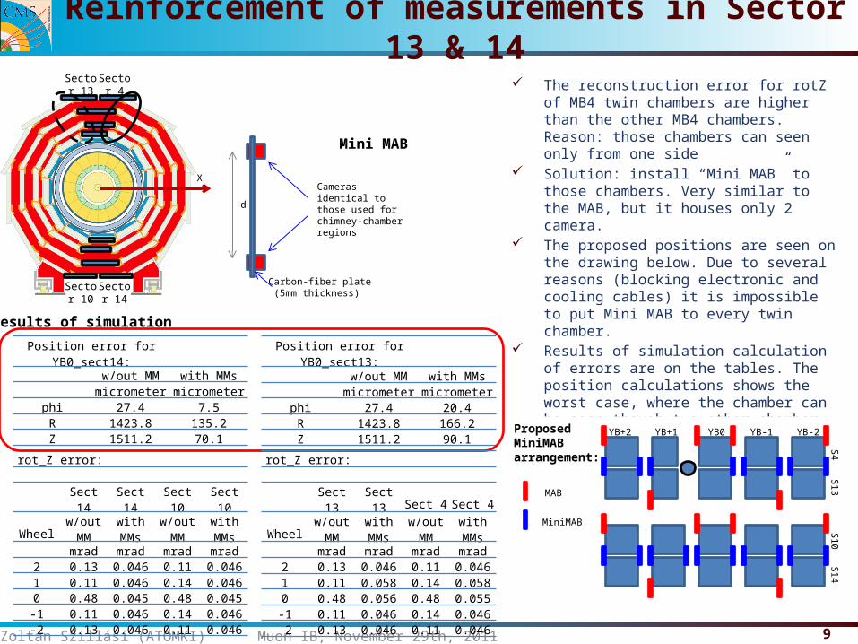
Reinforcement of measurements in Sector 13 & 14 The reconstruction error for rotZ of MB4 twin
chambers are higher than the other MB4 chambers.Reason: those chambers can seen only from one side
Solution: install “Mini MAB” to those chambers. Very similar to the MAB, but it houses only 2 camera.
The proposed positions are seen on the drawing below. Due to several reasons (blocking electronic and cooling cables) it is impossible to put Mini MAB to every twin chamber.
Results of simulation calculation of errors are on the tables. The position calculations shows the worst case, where the chamber can be seen though two other chamber.
With the Mini MABs the alignment precision for these chambers will be better.
Sector 13
Sector 14
Sector 4
Sector 10
X
Position error for YB0_sect13:w/out MM with MMsmicrometer micrometer
phi 27.4 20.4R 1423.8 166.2Z 1511.2 90.1
rot_Z error:
Sect 14 Sect 14 Sect 10 Sect 10
Wheelw/out MM
with MMs
w/out MM
with MMs
mrad mrad mrad mrad2 0.13 0.046 0.11 0.0461 0.11 0.046 0.14 0.0460 0.48 0.045 0.48 0.045-1 0.11 0.046 0.14 0.046-2 0.13 0.046 0.11 0.046
Position error for YB0_sect14:w/out MM with MMsmicrometer micrometer
phi 27.4 7.5R 1423.8 135.2Z 1511.2 70.1
Results of simulation
Cameras identical to those used for chimney-chamber regions
d
Carbon-fiber plate (5mm thickness)
Mini MAB
YB+2 YB+1 YB0 YB-1 YB-2
S4
Proposed MiniMABarrangement:
MAB
MiniMAB
S13S10
S14
rot_Z error:
Sect 13 Sect 13 Sect 4 Sect 4
Wheelw/out MM
with MMs
w/out MM
with MMs
mrad mrad mrad mrad2 0.13 0.046 0.11 0.0461 0.11 0.058 0.14 0.0580 0.48 0.056 0.48 0.055-1 0.11 0.046 0.14 0.046-2 0.13 0.046 0.11 0.046
10Zoltán Szillási (ATOMKI) Muon IB, November 29th, 2011
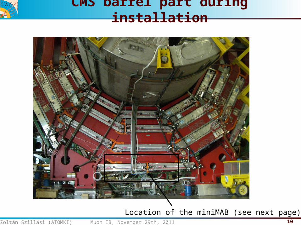
CMS barrel part during installation
Location of the miniMAB (see next page)
11Zoltán Szillási (ATOMKI) Muon IB, November 29th, 2011
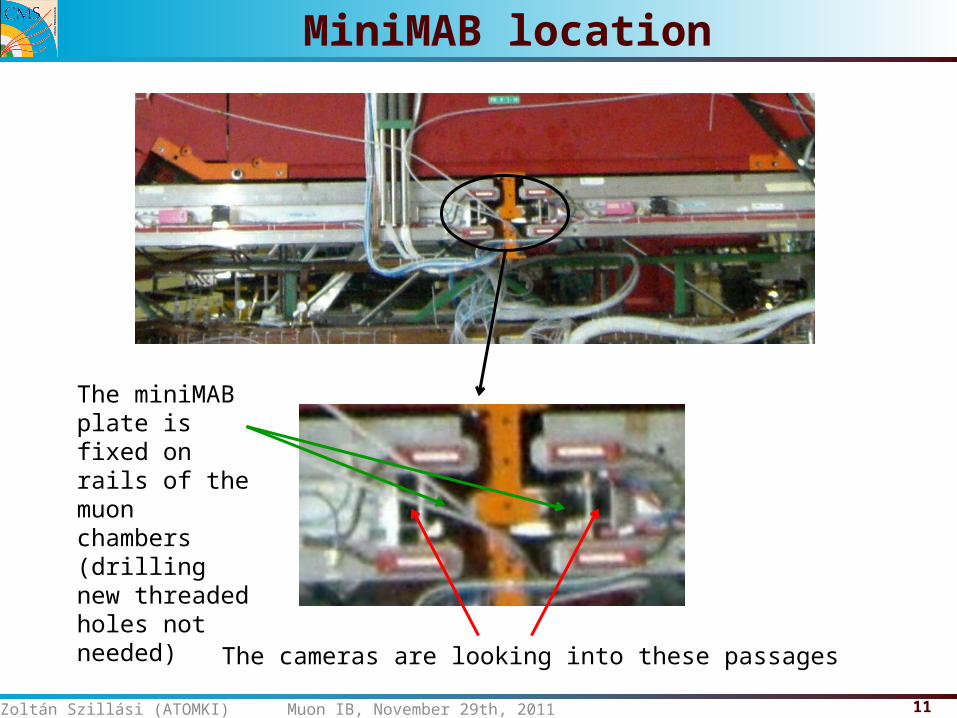
MiniMAB location
The miniMAB plate is fixed on rails of the muon chambers(drilling new threaded holes not needed)
The cameras are looking into these passages
12Zoltán Szillási (ATOMKI) Muon IB, November 29th, 2011
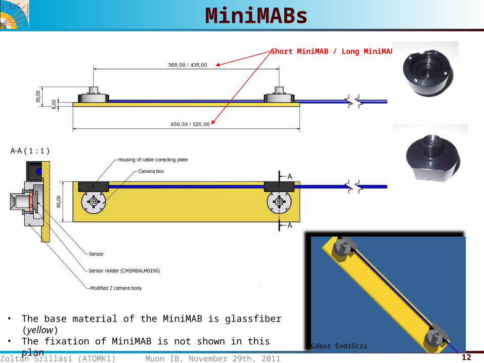
MiniMABsShort MiniMAB / Long MiniMAB
• The base material of the MiniMAB is glassfiber (yellow)• The fixation of MiniMAB is not shown in this plan
Gábor Endrőczi
13Zoltán Szillási (ATOMKI) Muon IB, November 29th, 2011
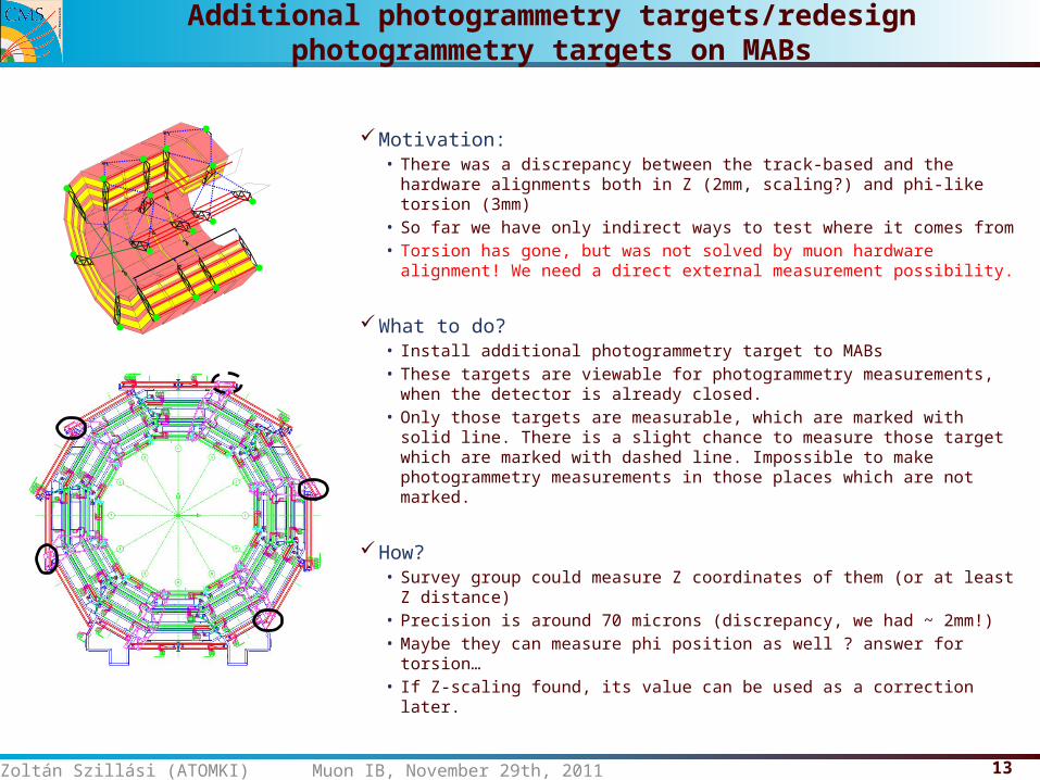
Additional photogrammetry targets/redesign photogrammetry targets on MABs
Motivation:• There was a discrepancy between the track-based and the hardware
alignments both in Z (2mm, scaling?) and phi-like torsion (3mm)• So far we have only indirect ways to test where it comes from• Torsion has gone, but was not solved by muon hardware alignment!
We need a direct external measurement possibility.
What to do?• Install additional photogrammetry target to MABs• These targets are viewable for photogrammetry measurements, when
the detector is already closed.• Only those targets are measurable, which are marked with solid line.
There is a slight chance to measure those target which are marked with dashed line. Impossible to make photogrammetry measurements in those places which are not marked.
How?• Survey group could measure Z coordinates of them (or at least Z
distance)• Precision is around 70 microns (discrepancy, we had ~ 2mm!)• Maybe they can measure phi position as well ? answer for torsion…• If Z-scaling found, its value can be used as a correction later.
14Zoltán Szillási (ATOMKI) Muon IB, November 29th, 2011
Map of Survey points in UXC
• 2011 September TS -- Visual inspection has been done on the possibility on the MAB visibility and mounting of new Survey brackets on the UXC wall
• 2011 December (at B=0) final position of brackets were measured (planned to have some installation, but didn’t happen)
15Zoltán Szillási (ATOMKI) Muon IB, November 29th, 2011
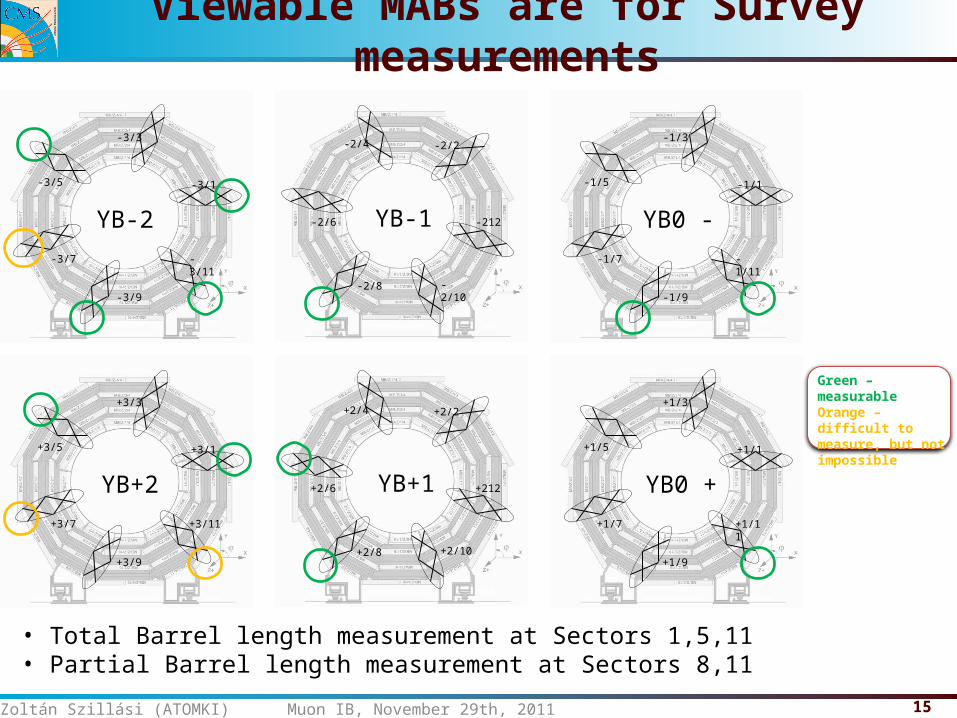
Viewable MABs are for Survey measurements
YB0 -
-1/1
-1/3
-1/5
-1/7
-1/9
-1/11
YB+2
+3/1
+3/3
+3/5
+3/7
+3/9
+3/11
YB-2
-3/1
-3/3
-3/5
-3/7
-3/9
-3/11
YB0 +
+1/1
+1/3
+1/5
+1/7
+1/9
+1/11
YB+1
+2/2+2/4
+2/6
+2/8 +2/10
+212
YB-1
-2/2-2/4
-2/6
-2/8 -2/10
-212
Green – measurableOrange – difficult to measure, but not impossible
• Total Barrel length measurement at Sectors 1,5,11• Partial Barrel length measurement at Sectors 8,11
16Zoltán Szillási (ATOMKI) Muon IB, November 29th, 2011
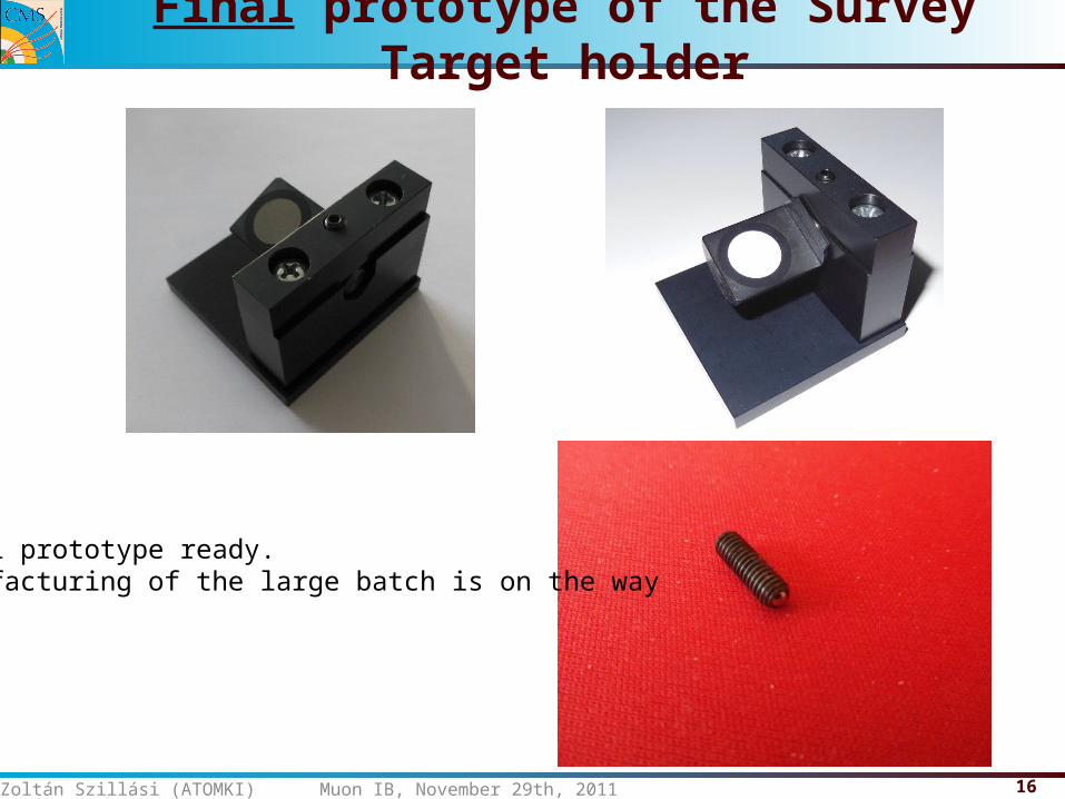
Final prototype of the Survey Target holder
Final prototype ready.Manufacturing of the large batch is on the way
17Zoltán Szillási (ATOMKI) Muon IB, November 29th, 2011
Evacuation of BoardPC from the gaps
The BoardPC placed between the gaps of the CMS barrel wheels in order to be close to the MABs.
These PCs control some part of LEDs and digitalize and analyze the images of the cameras of MABs
They are unreachable when the CMS wheels are closed. CMS barrel wheels was open last time in the beginning of 2008 and they are not expected to be open more frequently after LS1.
After the failures of image grabbers cards of some BoardPCs, we started to think about to evacuate them to the side of the YBs (we had 3 at the beginning, now we have 7).
The possible places to install the BoardPCs has been checked During 2011 November TS.
18Zoltán Szillási (ATOMKI) Muon IB, November 29th, 2011
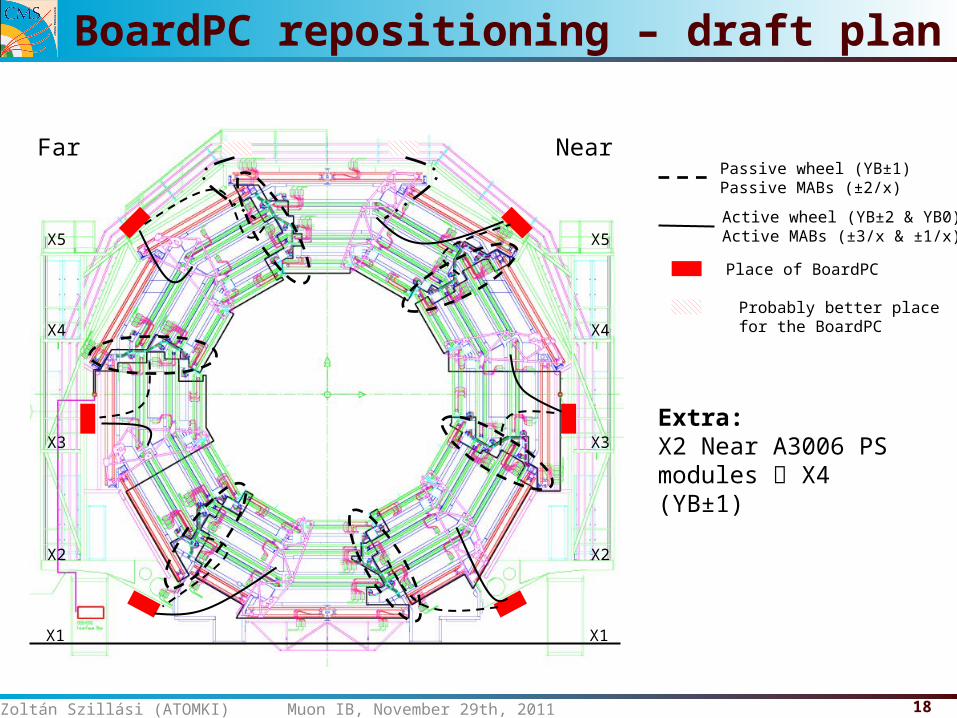
BoardPC repositioning – draft plan
X1
X2
X3
X4
X5
X1
X2
X3
X4
X5
Far NearPassive wheel (YB±1)Passive MABs (±2/x)
Active wheel (YB±2 & YB0)Active MABs (±3/x & ±1/x)
Place of BoardPC
Probably better place for the BoardPC
Extra:X2 Near A3006 PS modules X4 (YB±1)
19Zoltán Szillási (ATOMKI) Muon IB, November 29th, 2011
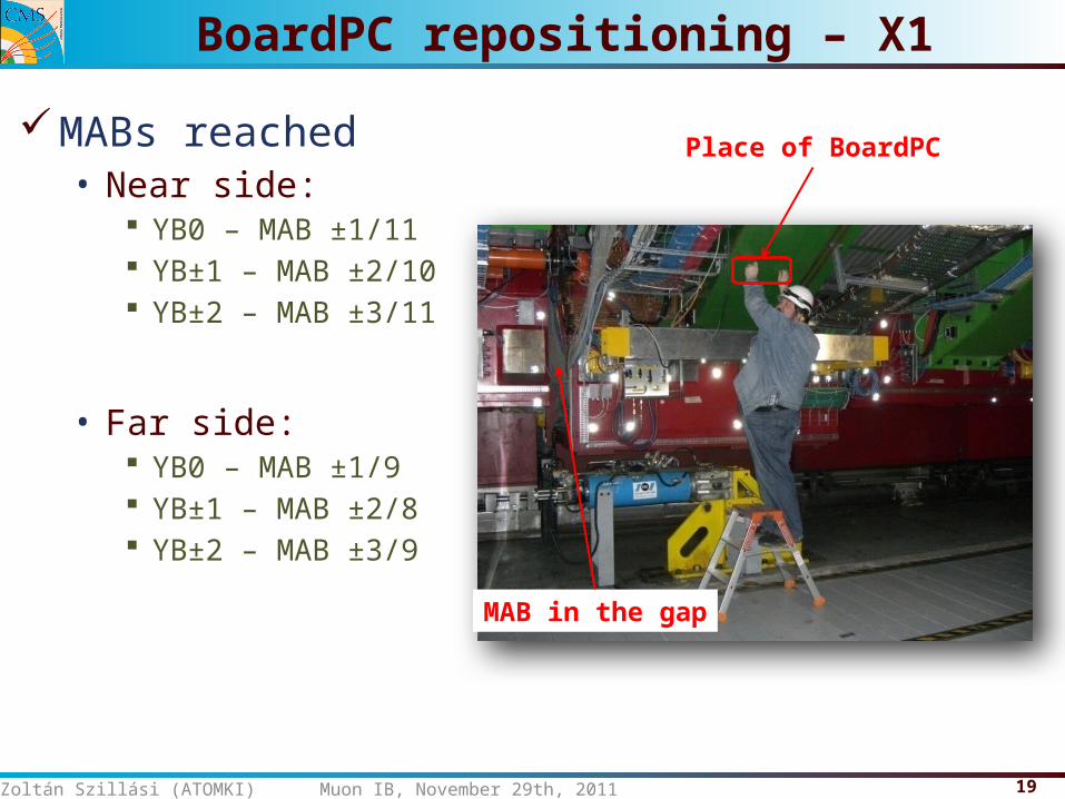
BoardPC repositioning – X1
MABs reached• Near side:
YB0 – MAB ±1/11 YB±1 – MAB ±2/10 YB±2 – MAB ±3/11
• Far side: YB0 – MAB ±1/9 YB±1 – MAB ±2/8 YB±2 – MAB ±3/9
Place of BoardPC
MAB in the gap
20Zoltán Szillási (ATOMKI) Muon IB, November 29th, 2011
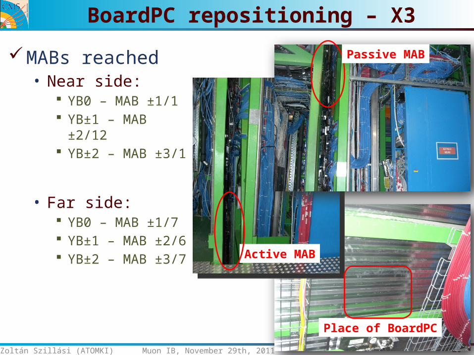
BoardPC repositioning – X3
MABs reached• Near side:
YB0 – MAB ±1/1 YB±1 – MAB ±2/12 YB±2 – MAB ±3/1
• Far side: YB0 – MAB ±1/7 YB±1 – MAB ±2/6 YB±2 – MAB ±3/7
Passive MAB
Active MAB
Place of BoardPC
21Zoltán Szillási (ATOMKI) Muon IB, November 29th, 2011
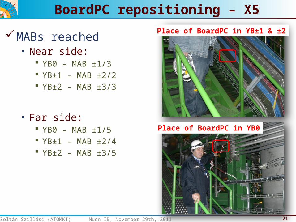
BoardPC repositioning – X5
MABs reached• Near side:
YB0 – MAB ±1/3 YB±1 – MAB ±2/2 YB±2 – MAB ±3/3
• Far side: YB0 – MAB ±1/5 YB±1 – MAB ±2/4 YB±2 – MAB ±3/5
Place of BoardPC in YB0
Place of BoardPC in YB±1 & ±2
22Zoltán Szillási (ATOMKI) Muon IB, November 29th, 2011
Status of the Upgrade
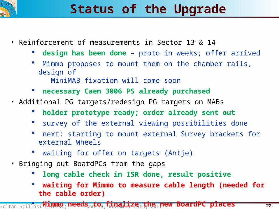
• Reinforcement of measurements in Sector 13 & 14 design has been done – proto in weeks; offer arrived Mimmo proposes to mount them on the chamber rails, design of
MiniMAB fixation will come soon necessary Caen 3006 PS already purchased
• Additional PG targets/redesign PG targets on MABs holder prototype ready; order already sent out survey of the external viewing possibilities done next: starting to mount external Survey brackets for external Wheels waiting for offer on targets (Antje)
• Bringing out BoardPCs from the gaps long cable check in ISR done, result positive waiting for Mimmo to measure cable length (needed for the cable order) Mimmo needs to finalize the new BoardPC places
23Zoltán Szillási (ATOMKI) Muon IB, November 29th, 2011
Long-term upgrade plans
Eliminate the single failure point caused by the single frame grabber card on the BoardPCs by changing the cameras to digital. Beside bringing the digitization to the individual cameras, this would allow parallel processing of data and better noise tolerance between the camera and the BoardPC.
We also wondering on changing the BoardPCs themselves since the technology will be more than 10 years old by then and the spare part supply will probably either impossible or unmaintainably expensive.
LS2 idea (not yet a proposal. First let’s get through LS1 ):
24Zoltán Szillási (ATOMKI) Muon IB, November 29th, 2011
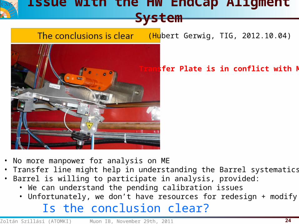
Issue with the HW EndCap Aligment System
(Hubert Gerwig, TIG, 2012.10.04)
• No more manpower for analysis on ME• Transfer line might help in understanding the Barrel systematics• Barrel is willing to participate in analysis, provided:
• We can understand the pending calibration issues• Unfortunately, we don’t have resources for redesign + modify
Transfer Plate is in conflict with ME4!
Is the conclusion clear?
25Yuriy Pakhotin (Texas A&M) Muon IB, November 29th, 2011
Back Up
26
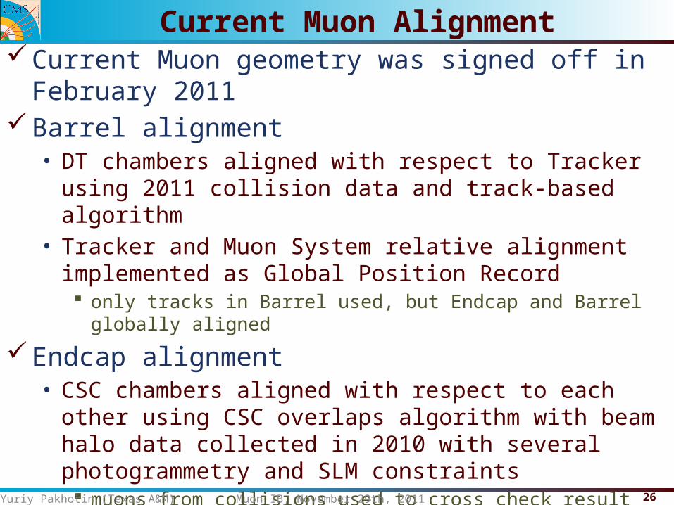
Current Muon geometry was signed off in February 2011Barrel alignment• DT chambers aligned with respect to Tracker using 2011 collision
data and track-based algorithm• Tracker and Muon System relative alignment implemented as
Global Position Record only tracks in Barrel used, but Endcap and Barrel globally aligned
Endcap alignment• CSC chambers aligned with respect to each other using CSC
overlaps algorithm with beam halo data collected in 2010 with several photogrammetry and SLM constraints muons from collisions used to cross check result with beam-halo, same
result within precision
• Endcap Rings aligned w.r.t. Tracker as rigid bodies global movement and rotation in plane perpendicular to beam line
Yuriy Pakhotin (Texas A&M) Muon IB, November 29th, 2011
Current Muon Alignment
27
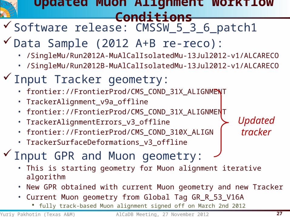
Software release: CMSSW_5_3_6_patch1Data Sample (2012 A+B re-reco):
• /SingleMu/Run2012A-MuAlCalIsolatedMu-13Jul2012-v1/ALCARECO• /SingleMu/Run2012B-MuAlCalIsolatedMu-13Jul2012-v1/ALCARECO
Input Tracker geometry:• frontier://FrontierProd/CMS_COND_31X_ALIGNMENT• TrackerAlignment_v9a_offline• frontier://FrontierProd/CMS_COND_31X_ALIGNMENT• TrackerAlignmentErrors_v3_offline• frontier://FrontierProd/CMS_COND_310X_ALIGN• TrackerSurfaceDeformations_v3_offline
Input GPR and Muon geometry:• This is starting geometry for Muon alignment iterative algorithm• New GPR obtained with current Muon geometry and new Tracker• Current Muon geometry from Global Tag GR_R_53_V16A
fully track-based Muon alignment signed off on March 2nd 2012
Yuriy Pakhotin (Texas A&M) AlCaDB Meeting, 27 November 2012
Updated Muon Alignment Workflow Conditions
Updatedtracker
28
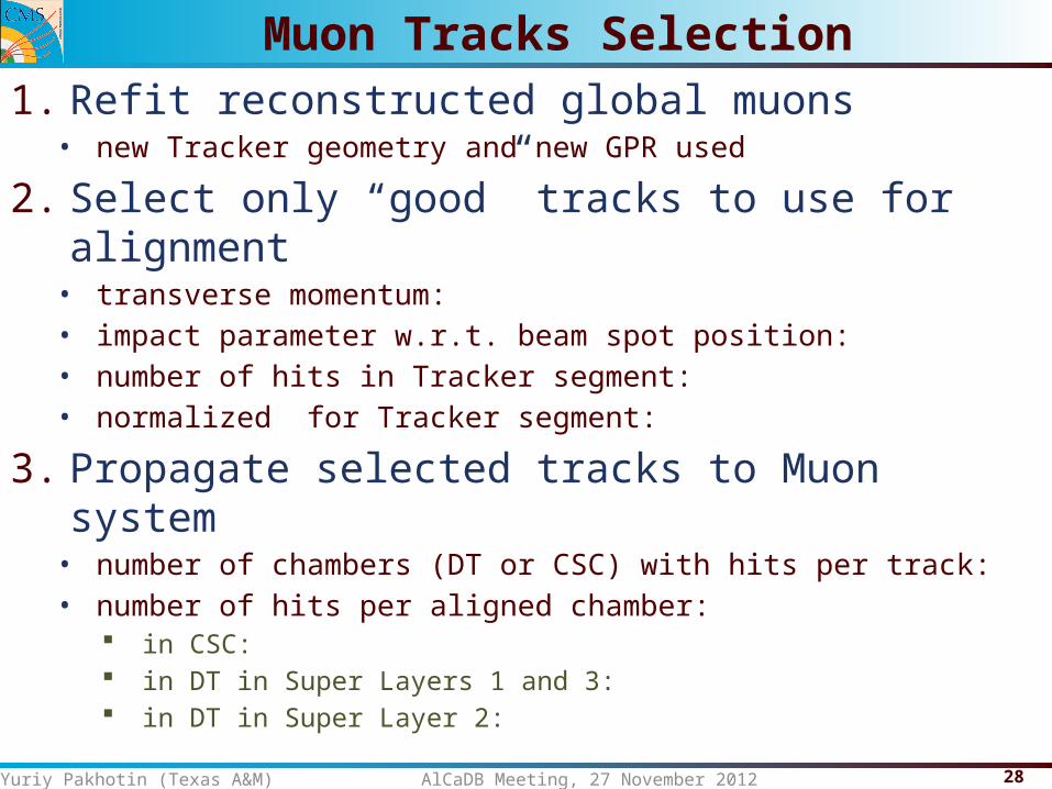
1. Refit reconstructed global muons• new Tracker geometry and new GPR used
2. Select only “good” tracks to use for alignment• transverse momentum: • impact parameter w.r.t. beam spot position: • number of hits in Tracker segment: • normalized for Tracker segment:
3. Propagate selected tracks to Muon system• number of chambers (DT or CSC) with hits per track: • number of hits per aligned chamber:
in CSC: in DT in Super Layers 1 and 3: in DT in Super Layer 2:
Yuriy Pakhotin (Texas A&M) AlCaDB Meeting, 27 November 2012
Muon Tracks Selection
29
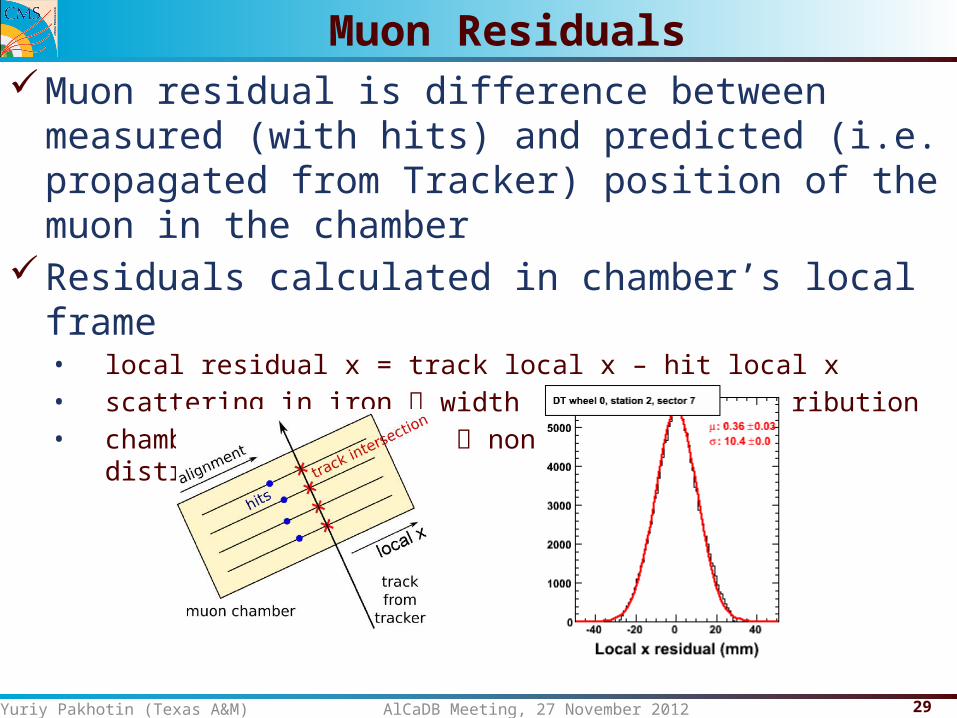
Muon residual is difference between measured (with hits) and predicted (i.e. propagated from Tracker) position of the muon in the chamber
Residuals calculated in chamber’s local frame• local residual x = track local x – hit local x• scattering in iron width of residual distribution• chamber misalignment non-zero mean of distribution
Yuriy Pakhotin (Texas A&M) AlCaDB Meeting, 27 November 2012
Muon Residuals
30
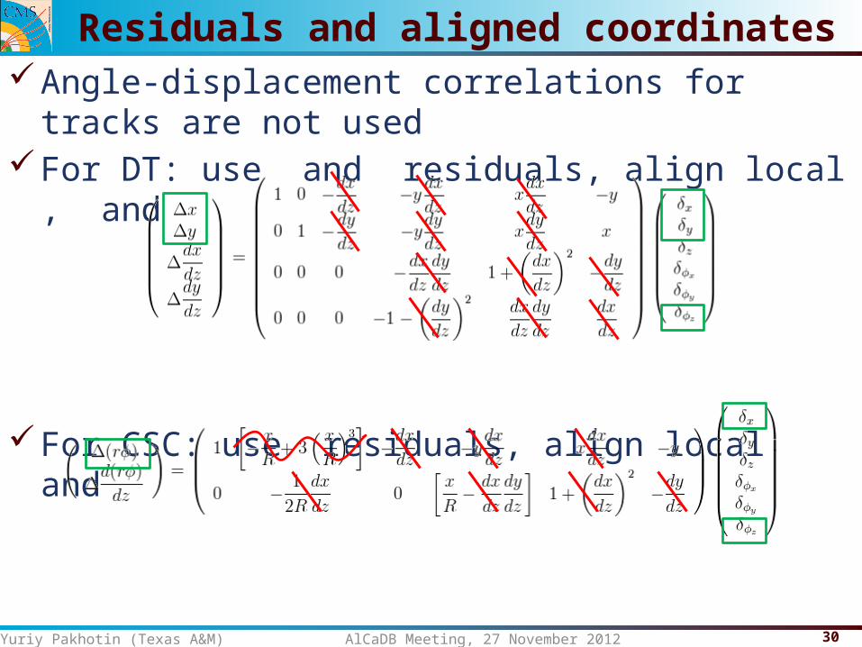
Angle-displacement correlations for tracks are not usedFor DT: use and residuals, align local , and
For CSC: use residuals, align local and
NOTE: Muon chambers aligned independently
Yuriy Pakhotin (Texas A&M) AlCaDB Meeting, 27 November 2012
Residuals and aligned coordinates
31
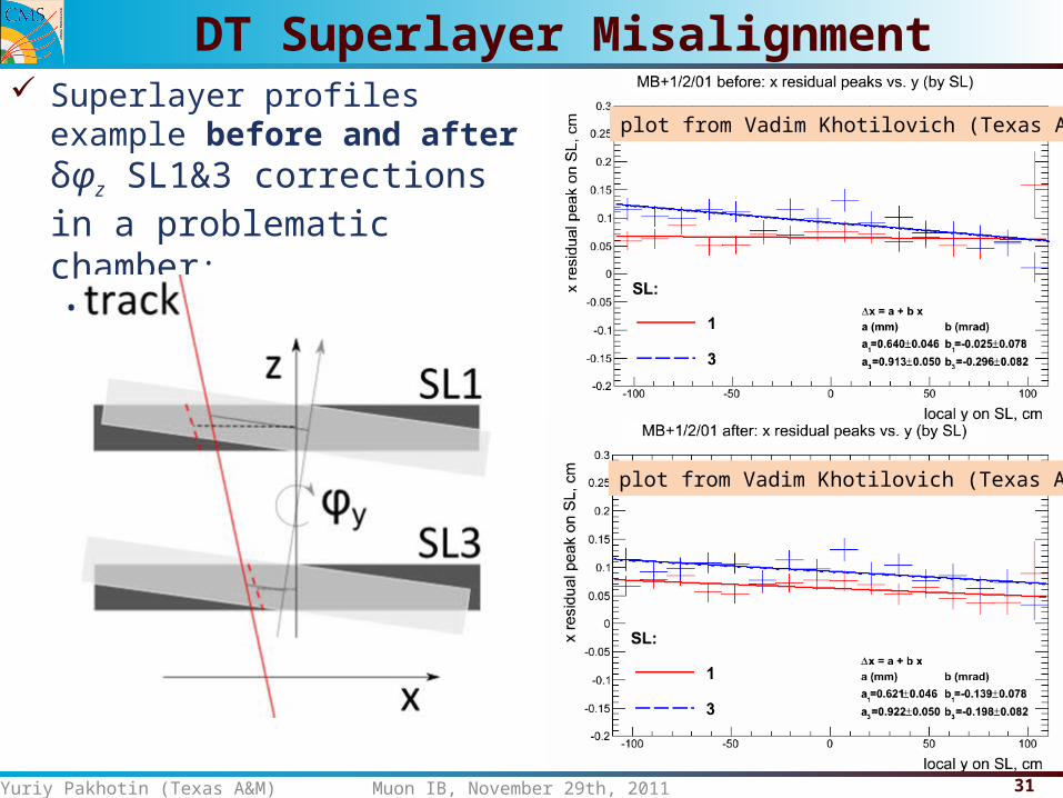
Superlayer profiles example before and after δφz SL1&3 corrections in a problematic chamber:• Slopes of superlayers become very close
Yuriy Pakhotin (Texas A&M) Muon IB, November 29th, 2011
DT Superlayer Misalignment
plot from Vadim Khotilovich (Texas A&M)
plot from Vadim Khotilovich (Texas A&M)