Embed Size (px)
Citation preview
STATUS OF THE MANUFACTURING OF ACCELERATING STRUCTURES FOR LINACS
F. Mirapeix#, J. Castillo, A. Ortiz, J. Añel, HTS, Mendaro, Spain A. Urzainki, X. Aldalur, J. Amores, DMP, Mendaro, Spain
Abstract Particle accelerators need ongoing development in the
state of the art of the field: high-quality manufacturing of accelerating structures, PETS, but also drift tubes, bunchers, high-power couplers, alignment systems, precision test stands, etc. They also require engineering projects in the range of mechatronics, thermodynamics, microwaves, ultra high vacuum, cryogenics, joining techniques, high precision manufacturing, 3D high precision scanning, etc. HTS together with DMP are actually working on all this fronts. In this paper, the actual status of the manufacturing capabilities concerning some accelerating structures will be described.
INTRODUCTION The field of ultra high precision mechanics requires
considerable experience, not only in frequently used materials like aluminum or steel (all kinds) but also in titanium, invar, OFE copper, armco, nimonic, niobium, SiC, etc. Ultra high precision can only be achieved in a fully controlled process in which room temperature is rigorously controlled with accuracy within ±0.5 ºC and the drift (gradient) is lower than 0.2 ºC/hour and <0.4 ºC/day (in order to avoid noise due to thermal dilatation).
Figure 1: Impact on OFE copper of a 3D CMM sensor; 0.1 N, 0.8 mm Ø.
Computer numeric control (CNC) machines for lathing, milling and electric discharge machining (EDM) must enable dynamic control as a function of the temperature
of the piece being machined and the temperature of the spindle if ultra high precision shape and finish roughness must be performed (Ra below 5 nm has been achieved). All manufactured pieces must be 3D scanned on site; high precision and ultra low probing force (0.001 N) 3D coordinate measuring machine (CMM) with accuracy below 0.3 µm is used to validate devices in a clean and temperature-controlled environment. Higher forces can damage the pieces beyond the specifications (Figure 1).
Other kind of devices combining interferometry and confocal techniques are also necessary for high precision non-contact measurements (resolution below 0.1 nm).
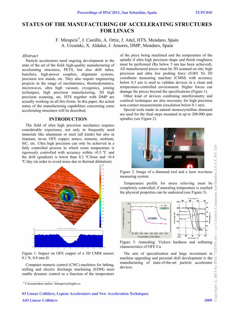
Special tools made in natural monocrystalline diamond are used for the final steps mounted in up to 200.000 rpm spindles (see Figure 2).
Figure 2: Image of a diamond tool and a laser waviness measuring system.
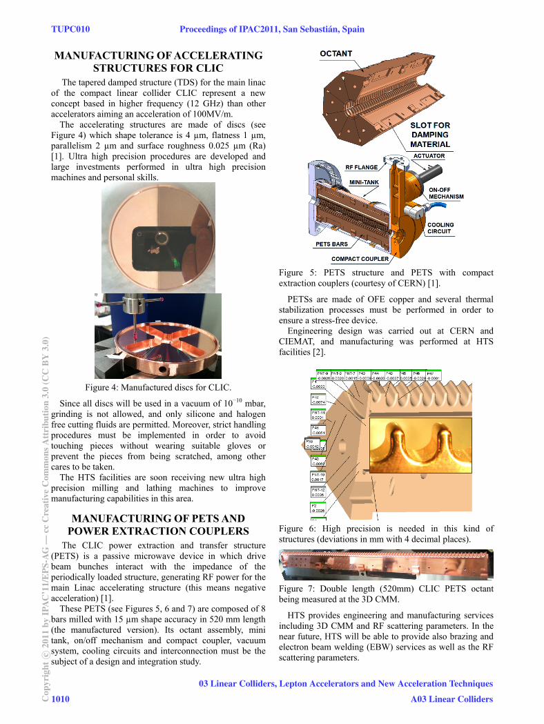
Temperature profile for stress relieving must be completely controlled; if annealing temperature is reached the physical properties can be undesired (see Figure 3).
Figure 3: Annealing: Vickers hardness and softening characteristics of OFE Cu.
The aim of specialization and large investment in machine upgrading and personal skill development is the manufacturing of state-of-the-art particle accelerator devices.
___________________________________________ # Correspondent author: [email protected]
Proceedings of IPAC2011, San Sebastián, Spain TUPC010
03 Linear Colliders, Lepton Accelerators and New Acceleration Techniques
A03 Linear Colliders 1009 Cop
yrig
htc ○
2011
byIP
AC
’11/
EPS
-AG
—cc
Cre
ativ
eC
omm
onsA
ttri
butio
n3.
0(C
CB
Y3.
0)
MANUFACTURING OF ACCELERATING STRUCTURES FOR CLIC
The tapered damped structure (TDS) for the main linac of the compact linear collider CLIC represent a new concept based in higher frequency (12 GHz) than other accelerators aiming an acceleration of 100MV/m.
The accelerating structures are made of discs (see Figure 4) which shape tolerance is 4 µm, flatness 1 µm, parallelism 2 µm and surface roughness 0.025 µm (Ra) [1]. Ultra high precision procedures are developed and large investments performed in ultra high precision machines and personal skills.
Figure 4: Manufactured discs for CLIC.
Since all discs will be used in a vacuum of 10−10 mbar, grinding is not allowed, and only silicone and halogen free cutting fluids are permitted. Moreover, strict handling procedures must be implemented in order to avoid touching pieces without wearing suitable gloves or prevent the pieces from being scratched, among other cares to be taken.
The HTS facilities are soon receiving new ultra high precision milling and lathing machines to improve manufacturing capabilities in this area.
MANUFACTURING OF PETS AND POWER EXTRACTION COUPLERS
The CLIC power extraction and transfer structure (PETS) is a passive microwave device in which drive beam bunches interact with the impedance of the periodically loaded structure, generating RF power for the main Linac accelerating structure (this means negative acceleration) [1].
These PETS (see Figures 5, 6 and 7) are composed of 8 bars milled with 15 µm shape accuracy in 520 mm length (the manufactured version). Its octant assembly, mini tank, on/off mechanism and compact coupler, vacuum system, cooling circuits and interconnection must be the subject of a design and integration study.
Figure 5: PETS structure and PETS with compact extraction couplers (courtesy of CERN) [1].
PETSs are made of OFE copper and several thermal stabilization processes must be performed in order to ensure a stress-free device.
Engineering design was carried out at CERN and CIEMAT, and manufacturing was performed at HTS facilities [2].
Figure 6: High precision is needed in this kind of structures (deviations in mm with 4 decimal places).
Figure 7: Double length (520mm) CLIC PETS octant being measured at the 3D CMM.
HTS provides engineering and manufacturing services including 3D CMM and RF scattering parameters. In the near future, HTS will be able to provide also brazing and electron beam welding (EBW) services as well as the RF scattering parameters.
TUPC010 Proceedings of IPAC2011, San Sebastián, Spain
1010Cop
yrig
htc ○
2011
byIP
AC
’11/
EPS
-AG
—cc
Cre
ativ
eC
omm
onsA
ttri
butio
n3.
0(C
CB
Y3.
0)
03 Linear Colliders, Lepton Accelerators and New Acceleration Techniques
A03 Linear Colliders
DRIFT TUBES FOR LINAC4 The goal of the Linac4 project is to build a 160 MeV
H− linear accelerator replacing Linac2 as injector. The new linac will increase the beam brightness by a factor of 2, making possible an upgrade of the LHC injectors.
The DTL is made of copper-plated stainless-steel vacuum tanks containing a series of precisely machined and aligned copper electrodes or drift tubes (see Figure 8) and will increase the beam energy from 3 MeV to 50 MeV. They are hollow cylindrical electrodes to which a radio-frequency voltage is applied in a linear accelerator (see Figure 8). The electric field developed between the drift tubes by means of powerful radio-frequency (RF) generators provides the acceleration to the particle beam. The heat deposited by the RF currents in the drift tubes and tank walls is removed by a water-cooling system.
Figure 8: Drift tube assembled from precision machined copper and stainless steel parts (courtesy of CERN).
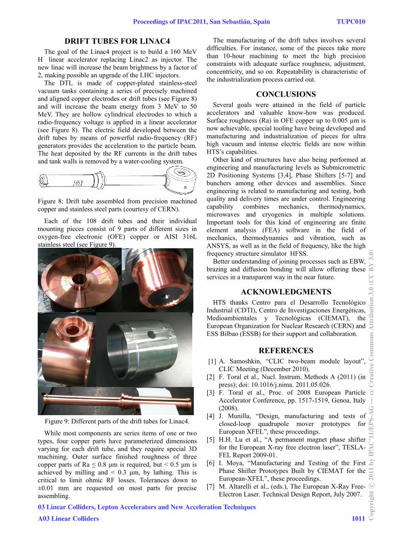
Each of the 108 drift tubes and their individual mounting pieces consist of 9 parts of different sizes in oxygen-free electronic (OFE) copper or AISI 316L stainless steel (see Figure 9).
Figure 9: Different parts of the drift tubes for Linac4.
While most components are series items of one or two types, four copper parts have parameterized dimensions varying for each drift tube, and they require special 3D machining. Outer surface finished roughness of three copper parts of Ra ≤ 0.8 μm is required, but < 0.5 μm is achieved by milling and < 0.3 μm, by lathing. This is critical to limit ohmic RF losses. Tolerances down to ±0.01 mm are requested on most parts for precise assembling.
The manufacturing of the drift tubes involves several difficulties. For instance, some of the pieces take more than 10-hour machining to meet the high precision constraints with adequate surface roughness, adjustment, concentricity, and so on. Repeatability is characteristic of the industrialization process carried out.
CONCLUSIONS Several goals were attained in the field of particle
accelerators and valuable know-how was produced. Surface roughness (Ra) in OFE copper up to 0.005 µm is now achievable, special tooling have being developed and manufacturing and industrialization of pieces for ultra high vacuum and intense electric fields are now within HTS’s capabilities.
Other kind of structures have also being performed at engineering and manufacturing levels as Submicrometric 2D Positioning Systems [3,4], Phase Shifters [5-7] and bunchers among other devices and assemblies. Since engineering is related to manufacturing and testing, both quality and delivery times are under control. Engineering capability combines mechanics, thermodynamics, microwaves and cryogenics in multiple solutions. Important tools for this kind of engineering are finite element analysis (FEA) software in the field of mechanics, thermodynamics and vibration, such as ANSYS, as well as in the field of frequency, like the high frequency structure simulator HFSS.
Better understanding of joining processes such as EBW, brazing and diffusion bonding will allow offering these services in a transparent way in the near future.
ACKNOWLEDGMENTS HTS thanks Centro para el Desarrollo Tecnológico
Industrial (CDTI), Centro de Investigaciones Energéticas, Medioambientales y Tecnológicas (CIEMAT), the European Organization for Nuclear Research (CERN) and ESS Bilbao (ESSB) for their support and collaboration.
REFERENCES [1] A. Samoshkin, “CLIC two-beam module layout”,
CLIC Meeting (December 2010). [2] F. Toral et al., Nucl. Instrum. Methods A (2011) (in
press); doi: 10.1016/j.nima. 2011.05.026. [3] F. Toral et al., Proc. of 2008 European Particle
Accelerator Conference, pp. 1517-1519, Genoa, Italy (2008).
[4] J. Munilla, “Design, manufacturing and tests of closed-loop quadrupole mover prototypes for European XFEL”, these proceedings.
[5] H.H. Lu et al., “A permanent magnet phase shifter for the European X-ray free electron laser”, TESLA-FEL Report 2009-01.
[6] I. Moya, “Manufacturing and Testing of the First Phase Shifter Prototypes Built by CIEMAT for the European-XFEL”, these proceedings.
[7] M. Altarelli et al., (eds.), The European X-Ray Free-Electron Laser. Technical Design Report, July 2007.
Proceedings of IPAC2011, San Sebastián, Spain TUPC010
03 Linear Colliders, Lepton Accelerators and New Acceleration Techniques
A03 Linear Colliders 1011 Cop
yrig
htc ○
2011
byIP
AC
’11/
EPS
-AG
—cc
Cre
ativ
eC
omm
onsA
ttri
butio
n3.
0(C
CB
Y3.
0)