Embed Size (px)
Citation preview
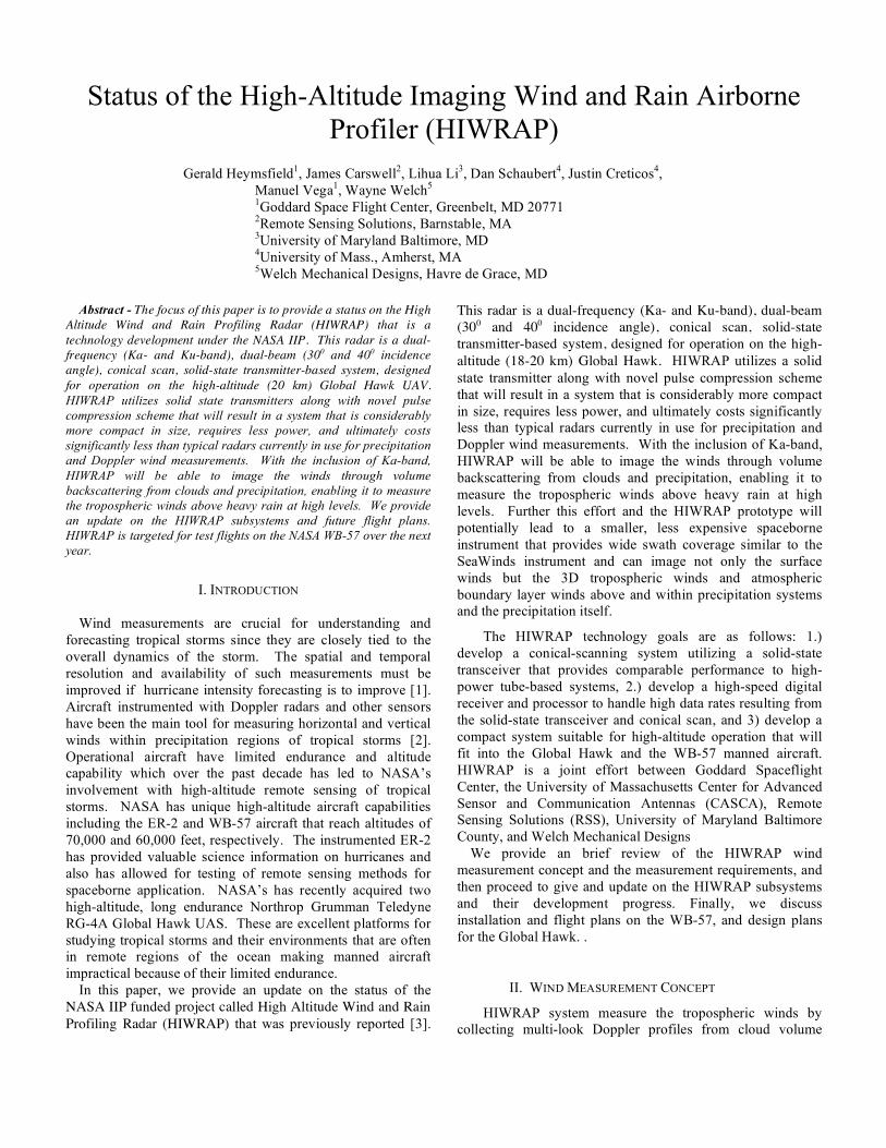
Status of the High-Altitude Imaging Wind and Rain Airborne Profiler (HIWRAP)
Gerald Heymsfield1, James Carswell2, Lihua Li3, Dan Schaubert4, Justin Creticos4, Manuel Vega1, Wayne Welch5
1Goddard Space Flight Center, Greenbelt, MD 20771 2Remote Sensing Solutions, Barnstable, MA 3University of Maryland Baltimore, MD 4University of Mass., Amherst, MA 5Welch Mechanical Designs, Havre de Grace, MD
Abstract - The focus of this paper is to provide a status on the High
Altitude Wind and Rain Profiling Radar (HIWRAP) that is a technology development under the NASA IIP. This radar is a dual-frequency (Ka- and Ku-band), dual-beam (300 and 400 incidence angle), conical scan, solid-state transmitter-based system, designed for operation on the high-altitude (20 km) Global Hawk UAV. HIWRAP utilizes solid state transmitters along with novel pulse compression scheme that will result in a system that is considerably more compact in size, requires less power, and ultimately costs significantly less than typical radars currently in use for precipitation and Doppler wind measurements. With the inclusion of Ka-band, HIWRAP will be able to image the winds through volume backscattering from clouds and precipitation, enabling it to measure the tropospheric winds above heavy rain at high levels. We provide an update on the HIWRAP subsystems and future flight plans. HIWRAP is targeted for test flights on the NASA WB-57 over the next year.
I. INTRODUCTION
Wind measurements are crucial for understanding and
forecasting tropical storms since they are closely tied to the overall dynamics of the storm. The spatial and temporal resolution and availability of such measurements must be improved if hurricane intensity forecasting is to improve [1]. Aircraft instrumented with Doppler radars and other sensors have been the main tool for measuring horizontal and vertical winds within precipitation regions of tropical storms [2]. Operational aircraft have limited endurance and altitude capability which over the past decade has led to NASA’s involvement with high-altitude remote sensing of tropical storms. NASA has unique high-altitude aircraft capabilities including the ER-2 and WB-57 aircraft that reach altitudes of 70,000 and 60,000 feet, respectively. The instrumented ER-2 has provided valuable science information on hurricanes and also has allowed for testing of remote sensing methods for spaceborne application. NASA’s has recently acquired two high-altitude, long endurance Northrop Grumman Teledyne RG-4A Global Hawk UAS. These are excellent platforms for studying tropical storms and their environments that are often in remote regions of the ocean making manned aircraft impractical because of their limited endurance.
In this paper, we provide an update on the status of the NASA IIP funded project called High Altitude Wind and Rain Profiling Radar (HIWRAP) that was previously reported [3].
This radar is a dual-frequency (Ka- and Ku-band), dual-beam (300 and 400 incidence angle), conical scan, solid-state transmitter-based system, designed for operation on the high-altitude (18-20 km) Global Hawk. HIWRAP utilizes a solid state transmitter along with novel pulse compression scheme that will result in a system that is considerably more compact in size, requires less power, and ultimately costs significantly less than typical radars currently in use for precipitation and Doppler wind measurements. With the inclusion of Ka-band, HIWRAP will be able to image the winds through volume backscattering from clouds and precipitation, enabling it to measure the tropospheric winds above heavy rain at high levels. Further this effort and the HIWRAP prototype will potentially lead to a smaller, less expensive spaceborne instrument that provides wide swath coverage similar to the SeaWinds instrument and can image not only the surface winds but the 3D tropospheric winds and atmospheric boundary layer winds above and within precipitation systems and the precipitation itself.
The HIWRAP technology goals are as follows: 1.) develop a conical-scanning system utilizing a solid-state transceiver that provides comparable performance to high-power tube-based systems, 2.) develop a high-speed digital receiver and processor to handle high data rates resulting from the solid-state transceiver and conical scan, and 3) develop a compact system suitable for high-altitude operation that will fit into the Global Hawk and the WB-57 manned aircraft. HIWRAP is a joint effort between Goddard Spaceflight Center, the University of Massachusetts Center for Advanced Sensor and Communication Antennas (CASCA), Remote Sensing Solutions (RSS), University of Maryland Baltimore County, and Welch Mechanical Designs
We provide an brief review of the HIWRAP wind measurement concept and the measurement requirements, and then proceed to give and update on the HIWRAP subsystems and their development progress. Finally, we discuss installation and flight plans on the WB-57, and design plans for the Global Hawk. .
II. WIND MEASUREMENT CONCEPT
HIWRAP system measure the tropospheric winds by collecting multi-look Doppler profiles from cloud volume
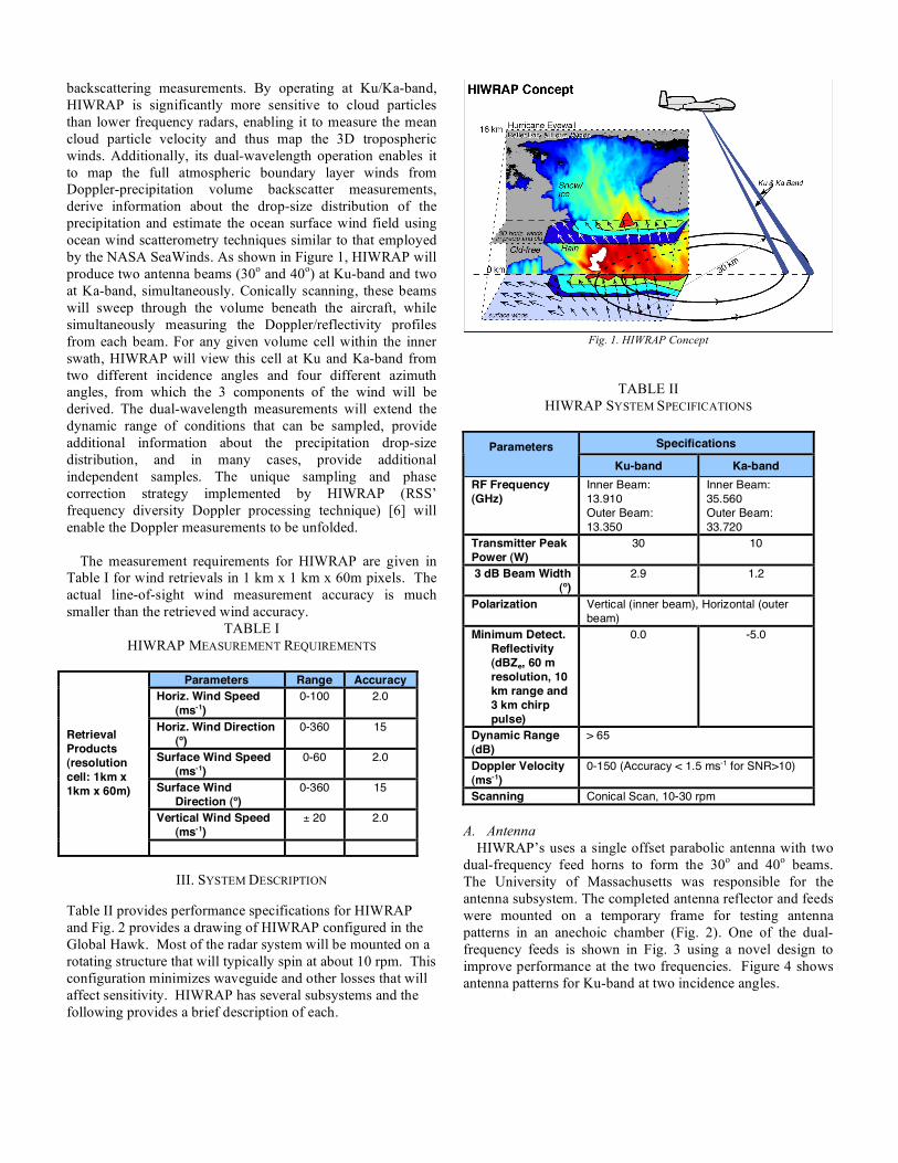
backscattering measurements. By operating at Ku/Ka-band, HIWRAP is significantly more sensitive to cloud particles than lower frequency radars, enabling it to measure the mean cloud particle velocity and thus map the 3D tropospheric winds. Additionally, its dual-wavelength operation enables it to map the full atmospheric boundary layer winds from Doppler-precipitation volume backscatter measurements, derive information about the drop-size distribution of the precipitation and estimate the ocean surface wind field using ocean wind scatterometry techniques similar to that employed by the NASA SeaWinds. As shown in Figure 1, HIWRAP will produce two antenna beams (30o and 40o) at Ku-band and two at Ka-band, simultaneously. Conically scanning, these beams will sweep through the volume beneath the aircraft, while simultaneously measuring the Doppler/reflectivity profiles from each beam. For any given volume cell within the inner swath, HIWRAP will view this cell at Ku and Ka-band from two different incidence angles and four different azimuth angles, from which the 3 components of the wind will be derived. The dual-wavelength measurements will extend the dynamic range of conditions that can be sampled, provide additional information about the precipitation drop-size distribution, and in many cases, provide additional independent samples. The unique sampling and phase correction strategy implemented by HIWRAP (RSS’ frequency diversity Doppler processing technique) [6] will enable the Doppler measurements to be unfolded.
The measurement requirements for HIWRAP are given in
Table I for wind retrievals in 1 km x 1 km x 60m pixels. The actual line-of-sight wind measurement accuracy is much smaller than the retrieved wind accuracy.
TABLE I HIWRAP MEASUREMENT REQUIREMENTS
Parameters Range Accuracy
Horiz. Wind Speed (ms-1)
0-100 2.0
Horiz. Wind Direction (o)
0-360 15
Surface Wind Speed (ms-1)
0-60 2.0
Surface Wind Direction (o)
0-360 15
Vertical Wind Speed (ms-1)
± 20 2.0
Retrieval Products (resolution cell: 1km x 1km x 60m)
III. SYSTEM DESCRIPTION Table II provides performance specifications for HIWRAP and Fig. 2 provides a drawing of HIWRAP configured in the Global Hawk. Most of the radar system will be mounted on a rotating structure that will typically spin at about 10 rpm. This configuration minimizes waveguide and other losses that will affect sensitivity. HIWRAP has several subsystems and the following provides a brief description of each.
Fig. 1. HIWRAP Concept
TABLE II
HIWRAP SYSTEM SPECIFICATIONS
Specifications Parameters Ku-band Ka-band
RF Frequency (GHz)
Inner Beam: 13.910 Outer Beam: 13.350
Inner Beam: 35.560 Outer Beam: 33.720
Transmitter Peak Power (W)
30 10
3 dB Beam Width (o)
2.9 1.2
Polarization Vertical (inner beam), Horizontal (outer beam)
Minimum Detect. Reflectivity (dBZe, 60 m resolution, 10 km range and 3 km chirp pulse)
0.0 -5.0
Dynamic Range (dB)
> 65
Doppler Velocity (ms-1)
0-150 (Accuracy < 1.5 ms-1 for SNR>10)
Scanning Conical Scan, 10-30 rpm A. Antenna
HIWRAP’s uses a single offset parabolic antenna with two dual-frequency feed horns to form the 30o and 40o beams. The University of Massachusetts was responsible for the antenna subsystem. The completed antenna reflector and feeds were mounted on a temporary frame for testing antenna patterns in an anechoic chamber (Fig. 2). One of the dual-frequency feeds is shown in Fig. 3 using a novel design to improve performance at the two frequencies. Figure 4 shows antenna patterns for Ku-band at two incidence angles.
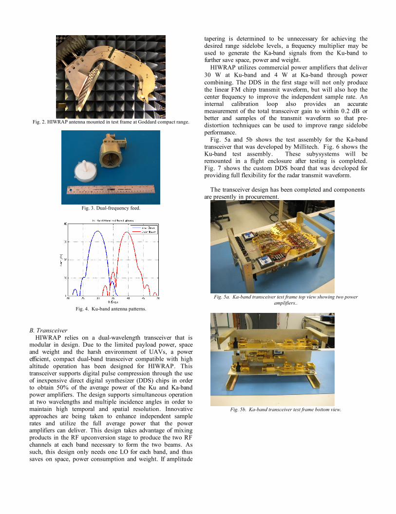
Fig. 2. HIWRAP antenna mounted in test frame at Goddard compact range.
Fig. 3. Dual-frequency feed.
Fig. 4. Ku-band antenna patterns.
B. Transceiver
HIWRAP relies on a dual-wavelength transceiver that is modular in design. Due to the limited payload power, space and weight and the harsh environment of UAVs, a power efficient, compact dual-band transceiver compatible with high altitude operation has been designed for HIWRAP. This transceiver supports digital pulse compression through the use of inexpensive direct digital synthesizer (DDS) chips in order to obtain 50% of the average power of the Ku and Ka-band power amplifiers. The design supports simultaneous operation at two wavelengths and multiple incidence angles in order to maintain high temporal and spatial resolution. Innovative approaches are being taken to enhance independent sample rates and utilize the full average power that the power amplifiers can deliver. This design takes advantage of mixing products in the RF upconversion stage to produce the two RF channels at each band necessary to form the two beams. As such, this design only needs one LO for each band, and thus saves on space, power consumption and weight. If amplitude
tapering is determined to be unnecessary for achieving the desired range sidelobe levels, a frequency multiplier may be used to generate the Ka-band signals from the Ku-band to further save space, power and weight.
HIWRAP utilizes commercial power amplifiers that deliver 30 W at Ku-band and 4 W at Ka-band through power combining. The DDS in the first stage will not only produce the linear FM chirp transmit waveform, but will also hop the center frequency to improve the independent sample rate. An internal calibration loop also provides an accurate measurement of the total transceiver gain to within 0.2 dB or better and samples of the transmit waveform so that pre-distortion techniques can be used to improve range sidelobe performance.
Fig. 5a and 5b shows the test assembly for the Ka-band transceiver that was developed by Millitech. Fig. 6 shows the Ku-band test assembly. These subysystems will be remounted in a flight enclosure after testing is completed. Fig. 7 shows the custom DDS board that was developed for providing full flexibility for the radar transmit waveform.
The transceiver design has been completed and components
are presently in procurement.
Fig. 5a. Ka-band transceiver test frame top view showing two power
amplifiers..
Fig. 5b. Ka-band transceiver test frame bottom view.
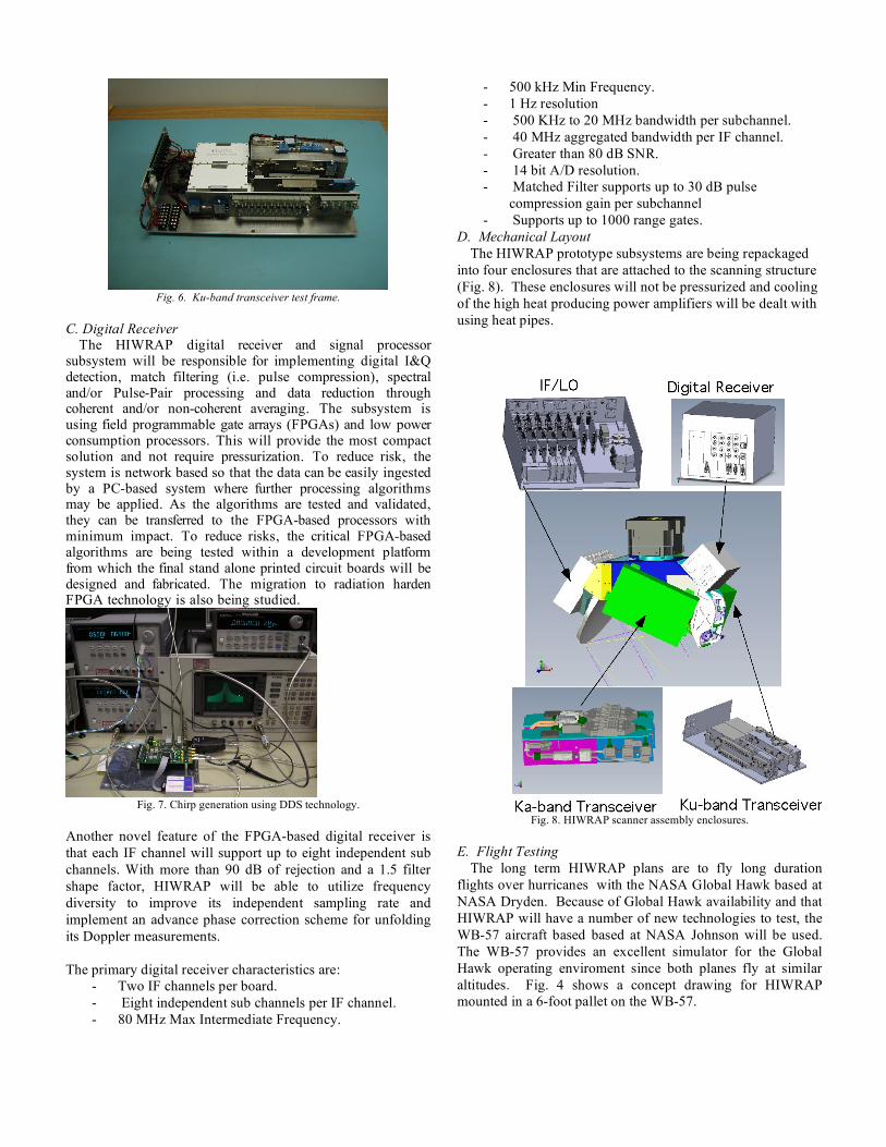
Fig. 6. Ku-band transceiver test frame.
C. Digital Receiver
The HIWRAP digital receiver and signal processor subsystem will be responsible for implementing digital I&Q detection, match filtering (i.e. pulse compression), spectral and/or Pulse-Pair processing and data reduction through coherent and/or non-coherent averaging. The subsystem is using field programmable gate arrays (FPGAs) and low power consumption processors. This will provide the most compact solution and not require pressurization. To reduce risk, the system is network based so that the data can be easily ingested by a PC-based system where further processing algorithms may be applied. As the algorithms are tested and validated, they can be transferred to the FPGA-based processors with minimum impact. To reduce risks, the critical FPGA-based algorithms are being tested within a development platform from which the final stand alone printed circuit boards will be designed and fabricated. The migration to radiation harden FPGA technology is also being studied.
Fig. 7. Chirp generation using DDS technology.
Another novel feature of the FPGA-based digital receiver is that each IF channel will support up to eight independent sub channels. With more than 90 dB of rejection and a 1.5 filter shape factor, HIWRAP will be able to utilize frequency diversity to improve its independent sampling rate and implement an advance phase correction scheme for unfolding its Doppler measurements. The primary digital receiver characteristics are:
- Two IF channels per board. - Eight independent sub channels per IF channel. - 80 MHz Max Intermediate Frequency.
- 500 kHz Min Frequency. - 1 Hz resolution - 500 KHz to 20 MHz bandwidth per subchannel. - 40 MHz aggregated bandwidth per IF channel. - Greater than 80 dB SNR. - 14 bit A/D resolution. - Matched Filter supports up to 30 dB pulse
compression gain per subchannel - Supports up to 1000 range gates.
D. Mechanical Layout The HIWRAP prototype subsystems are being repackaged
into four enclosures that are attached to the scanning structure (Fig. 8). These enclosures will not be pressurized and cooling of the high heat producing power amplifiers will be dealt with using heat pipes.
Fig. 8. HIWRAP scanner assembly enclosures.
E. Flight Testing
The long term HIWRAP plans are to fly long duration flights over hurricanes with the NASA Global Hawk based at NASA Dryden. Because of Global Hawk availability and that HIWRAP will have a number of new technologies to test, the WB-57 aircraft based based at NASA Johnson will be used. The WB-57 provides an excellent simulator for the Global Hawk operating enviroment since both planes fly at similar altitudes. Fig. 4 shows a concept drawing for HIWRAP mounted in a 6-foot pallet on the WB-57.
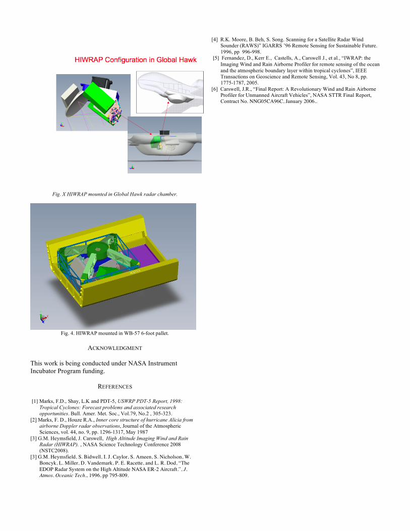
Fig. X HIWRAP mounted in Global Hawk radar chamber.
Fig. 4. HIWRAP mounted in WB-57 6-foot pallet.
ACKNOWLEDGMENT
This work is being conducted under NASA Instrument Incubator Program funding.
REFERENCES [1] Marks, F.D., Shay, L.K and PDT-5, USWRP PDT-5 Report, 1998:
Tropical Cyclones: Forecast problems and associated research opportunities. Bull. Amer. Met. Soc., Vol.79, No.2 , 305-323.
[2] Marks, F. D., Houze R.A., Inner core structure of hurricane Alicia from airborne Doppler radar observations, Journal of the Atmospheric Sciences, vol. 44, no. 9, pp. 1296-1317, May 1987
[3] G.M. Heymsfield, J. Carswell, High Altitude Imaging Wind and Rain Radar (HIWRAP). , NASA Science Technology Conference 2008 (NSTC2008).
[3] G.M. Heymsfield, S. Bidwell, I. J. Caylor, S. Ameen, S. Nicholson, W. Boncyk, L. Miller, D. Vandemark, P. E. Racette, and L. R. Dod, “The EDOP Radar System on the High Altitude NASA ER-2 Aircraft.”, J. Atmos. Oceanic Tech., 1996, pp 795-809.
[4] R.K. Moore, B. Beh, S. Song. Scanning for a Satellite Radar Wind Sounder (RAWS)” IGARRS ’96 Remote Sensing for Sustainable Future. 1996, pp 996-998.
[5] Fernandez, D., Kerr E., Castells, A., Carswell J., et al., “IWRAP: the Imaging Wind and Rain Airborne Profiler for remote sensing of the ocean and the atmospheric boundary layer within tropical cyclones”, IEEE Transactions on Geoscience and Remote Sensing, Vol. 43, No 8, pp. 1775-1787, 2005.
[6] Carswell, J.R., “Final Report: A Revolutionary Wind and Rain Airborne Profiler for Unmanned Aircraft Vehicles”, NASA STTR Final Report, Contract No. NNG05CA96C, January 2006..