Embed Size (px)
Citation preview

45th International Conference on Environmental Systems ICES-2015-073 12-16 July 2015, Bellevue, Washington
American Institute of Aeronautics and Astronautics
1
Status of ISS Water Management and Recovery
Layne Carter1 and Jennifer Pruitt2
NASA Marshall Space Flight Center, Huntsville, AL 35812
Christopher A. Brown3
Lockheed Martin Corporation, Houston, TX 77058
Ryan Schaezler4 and Lyndsey Bankers5
The Boeing Company, Houston, TX 77058
Water management on ISS is responsible for the provision of water to the crew for
drinking water, food preparation, and hygiene, to the Oxygen Generation System (OGS) for
oxygen production via electrolysis, to the Waste & Hygiene Compartment (WHC) for flush
water, and for experiments on ISS. This paper summarizes water management activities on
the ISS US Segment, and provides a status of the performance and issues related to the
operation of the Water Processor Assembly (WPA) and Urine Processor Assembly (UPA).
This paper summarizes the on-orbit status as of May 2015 and describes the technical
challenges encountered and lessons learned over the past two years.
I. Introduction
he International Space Station (ISS) Water Recovery and Management (WRM) System insures availability of
potable water for crew drinking and hygiene, oxygen generation, urinal flush water, and payloads as required. To
support this function, waste water is collected in the form of crew urine, humidity condensate, and Sabatier product
water, and subsequently processed by the Water Recovery System (WRS) into potable water. This product water is
provided to the potable bus for the various users, and may be stored in water bags for future use when the potable bus
needs supplementing. The WRS is comprised of the Urine Processor Assembly (UPA) and Water Processor Assembly
(WPA), which are located in two International Standard Payload Racks (ISPR) named WRS#1 and WRS#2. This
hardware was delivered to ISS on STS-126 on November 14, 2008 and initially installed in the US Lab module. On
February 18, 2010, the racks were transferred to their permanent home in the Node 3 module.
II. Description of the ISS Water Recovery and Management System
The ISS WRM provides the capability to receive the waste water on ISS (crew urine, humidity condensate, and
Sabatier product water), process the waste water to potable standards via the WRS, and distribute potable water to
users on the potable bus. A conceptual schematic of the WRM is provided in Figure 1. The waste water bus receives
humidity condensate from the Common Cabin Air Assemblies (CCAAs) on ISS, which condenses water vapor and
other condensable contaminants and delivers the condensate to the bus via a water separator. In addition, waste water
is also received from the Carbon Dioxide Reduction System. This hardware uses Sabatier technology to produce water
from carbon dioxide (from the Carbon Dioxide Removal Assembly (CDRA)) and hydrogen (from the electrolysis
process in the Oxygen Generation System). Waste water is typically delivered to the WPA Waste Tank. A separate
Condensate Tank located in the US Laboratory Module is available as a back-up in the event the WPA Waste Tank is
unavailable for waste water collection.
1 ISS Water Subsystem Manager, NASA MSFC ES62. 2 ISS Urine Processor Design Lead, NASA MSFC ES62. 3 ISS ETHOS, Lockheed Martin Corporation, Water Operations Lead for the Flight Operations Directorate. 4 ISS Water Recovery and Management Team Lead, The Boeing Company. 5 ISS Water Processor Team, The Boeing Company.
T
https://ntrs.nasa.gov/search.jsp?R=20150019535 2018-05-17T13:41:31+00:00Z

45th International Conference on Environmental Systems ICES-2015-073 12-16 July 2015, Bellevue, Washington
American Institute of Aeronautics and Astronautics
2
Figure 1. Water Recovery and Management Architecture for the ISS US Segment
Crew urine is collected in the Waste & Hygiene Compartment (WHC), which consists of a Russian Urinal system
(referred to as the ACY) that has been installed in the US Segment. To maintain chemical and microbial control of the
urine and hardware, the urine is treated with chemicals and flush water. The pretreated urine is then delivered to the
Urine Processor Assembly (UPA) for subsequent processing. The UPA produces urine distillate, which is pumped
directly to the WPA Waste Water Tank, where it is combined with the humidity condensate from the cabin and Sabatier
product water, and subsequently processed by the WPA. A detailed description of the UPA and WPA treatment
process is provided in Section III.
After the waste water is processed by the WRS, it is delivered to the potable bus. The potable bus is maintained at
a pressure of approximately 230 to 280 kPa (19 to 26.5 psig) so that water is available on demand from the various
users. Users of potable water on the bus include the Oxygen Generation System (OGS), the WHC (for flush water),
the Potable Water Dispenser (PWD) for crew consumption, the Extravehicular Mobility Unit (EMU) sublimator and
Payloads. Finally, a reserve of a minimum of 697 L of potable water is maintained on ISS in Iodinated Contingency
Water Containers (CWC-Is) and Potable Water Reservoirs (PWRs) to maintain ISS operations in response to
contingency scenarios.
III. Description of the ISS Water Recovery System
The layout of the two WRS racks is shown in Figure 2, along with the OGS. The WPA is packaged in WRS Rack
#1 and partially in WRS Rack #2, linked by process water lines running between the two racks. The remaining portion
of WRS Rack #2 houses the UPA.
WATER PROCESSOR ASSEMBLY (WPA)
Distillate Crew latent
Potable water
Oxygen
USOS CABIN
CREW - drinking - hygiene - urine
flush
BIOLOGICAL PAYLOADS
URINE PROCESSOR
ASSEMBLY (UPA)
OXYGEN GENERATOR
ASSEMBLY (OGA) • Solid Polymer Electrolysis (SPE)
Water Recovery System (WRS)
CO2 REDUCTION SYSTEM (CRS)
Pretreated Urine
• Sabatier Reactor
Carbon Dioxide
Hydrogen
Oxygen Generation System (OGS)
Water
overboard
- Rotary Gas Separator - Particulate Filter - Multifiltration Beds - Catalytic Oxidation Reactor
Vapor Compression
Distillation (VCD)
methane

45th International Conference on Environmental Systems ICES-2015-073 12-16 July 2015, Bellevue, Washington
American Institute of Aeronautics and Astronautics
3
Figure 2. International Space Station Regenerative ECLSS Racks
The following section provides a description of the WRS, current operational status, and describes issues and
lessons learned during the past year. For the prior years’ status, see references 1-4.
A. Water Processor Assembly Overview
A simplified schematic of the WPA is provided in Figure 3. The WPA is packaged into 16 Orbital Replacement
Units (ORU), and occupies WRS#1 and the right half of WRS#2. Wastewater delivered to the WPA includes
condensate from the Temperature and Humidity Control System, distillate from the UPA, and Sabatier product water.
This wastewater is temporarily stored in the Waste Water Tank ORU. The Waste Water Tank includes a bellows that
maintains a pressure of approximately 5.2 – 15.5 kPa (0.75 to 2.25 psig) over the tank cycle, which serves to push
water and gas into the Mostly Liquid Separator (MLS). Gas is removed from the wastewater by the MLS (part of the
Pump/Separator ORU), and passes through the Separator Filter ORU where odor-causing contaminants are removed
from entrained air before returning the air to the cabin. Next, the water is pumped through the Particulate Filter ORU
followed by two Multifiltration (MF) Beds where inorganic and non-volatile organic contaminants are removed. Once
breakthrough of the first bed is detected, the second bed is relocated into the first bed position, and a new second bed
is installed. The Sensor ORU located between the two MF beds determines when the first bed is saturated based on
conductivity. Following the MF Beds, the process water stream enters the Catalytic Reactor ORU, where low
molecular weight organics not removed by the adsorption process are oxidized in the presence of oxygen, elevated
temperature, and a catalyst. A regenerative heat exchanger recovers heat from the catalytic reactor effluent water to
make this process more efficient. The Gas Separator ORU removes excess oxygen and gaseous oxidation by-products
from the process water and returns it to the cabin. The Reactor Health Sensor ORU monitors the conductivity of the
reactor effluent as an indication of whether the organic load coming into the reactor is within the reactor’s oxidative
capacity. Finally, the Ion Exchange Bed ORU removes dissolved products of oxidation and adds iodine for residual
microbial control. The water is subsequently stored in the Water Storage Tank prior to delivery to the ISS potable
water bus. The Water Delivery ORU contains a pump and small accumulator tank to deliver potable water on demand
to users. The WPA is controlled by a firmware controller that provides the command control, excitation, monitoring,
and data downlink for WPA sensors and effectors.

45th International Conference on Environmental Systems ICES-2015-073 12-16 July 2015, Bellevue, Washington
American Institute of Aeronautics and Astronautics
4
Figure 3. WPA Simplified Schematic
B. Urine Processor Assembly Overview
A simplified schematic of the UPA is shown in Figure 4. The UPA is packaged into 7 ORUs, which take up slightly
more than half of the WRS Rack #2. Pretreated urine is delivered to the UPA either from the USOS Waste and Hygiene
Compartment (outfitted with a Russian urinal) or via manual transfer from the Russian urine container (called an
EDV). In either case, the composition of the pretreated urine is the same, including urine, flush water, and a
pretreatment formula containing chromium trioxide and sulfuric acid to control microbial growth and the reaction of
urea to ammonia. The urine is temporarily stored in the Wastewater Storage Tank Assembly (WSTA). When a
sufficient quantity of feed has been collected in the WSTA, a process cycle is automatically initiated. The Fluids
Control and Pump Assembly (FCPA) is a four-tube peristaltic pump that moves urine from the WSTA into the
Distillation Assembly (DA), recycles the concentrated waste from the DA into the Advanced Recycle Filter Tank
Assembly (ARFTA) and back to the DA, and pumps product distillate from the DA to the wastewater interface with
the WPA. The DA is the heart of the UPA, and consists of a rotating centrifuge where the waste urine stream is
evaporated at low pressure. The vapor is compressed and subsequently condensed on the opposite side of the
evaporator surface to conserve latent energy. A rotary lobe compressor provides the driving force for the evaporation
and compression of water vapor. Waste brine resulting from the distillation process is stored in the ARFTA, which is
a bellows tank that can be filled and drained on ISS. The ARFTA has less capacity (approximately 22 L) than the
RFTA (41 L), but the capability to fill and drain the ARFTA on ISS avoids the costly resupply penalty associated with
launching each RFTA. When the brine is concentrated to the required limit, the ARFTA is emptied into an EDV, a
Temporary Urine Brine Storage System (TUBSS), a Russian Rodnik tank on the Progress vehicle, or into the water
tanks on the ATV vehicle. Upon next installation, it is refilled with pretreated urine, which allows the process to
repeat. The Pressure Control and Pump Assembly (PCPA) is another four-tube peristaltic pump which provides for
the removal of non-condensable gases and water vapor from the DA. Liquid cooling of the pump housing promotes
condensation, thus reducing the required volumetric capacity of the peristaltic pump. Gases and condensed water are
pumped to the Separator Plumbing Assembly (SPA), which recovers and returns water from the purge gases to the
product water stream. A Firmware Controller Assembly (FCA) provides the command control, excitation, monitoring,
and data downlink for UPA sensors and effectors.
Ion Exchange Bed (removes reactor by-products)
Reactor
(oxidizes
organics)
Preheater
(heats water
to 275F)
Regen. HX
(recovers
heat)
Gas/Liquid
Separator
(removes
oxygen)
Particulate Filter
(removes
particulates)
Multifiltration Beds
(remove dissolved contaminants)
Mostly
Liquid
Separator
(removes air)
Filter
Pump
Wastewater
Tank
Product
Water
Tank
Delivery
Pump
Accumulator
O2
from
Node 3
To Node 3 cabin
to Node 3
cabin
from
Node 3
wastewater
bus
to
Node 3
potable
water
bus
Heat
Exchanger
to/from
Node 3
MTL
Reject Line
(allows reprocessing)
Microbial
Check Valve
(provides isolation)
C
C
Reactor Health
Sensor
(verifies reactor
is operating w/n
limits)C
C
Ion Exchange Bed (removes reactor by-products)
Reactor
(oxidizes
organics)
Preheater
(heats water
to 275F)
Regen. HX
(recovers
heat)
Gas/Liquid
Separator
(removes
oxygen)
Particulate Filter
(removes
particulates)
Multifiltration Beds
(remove dissolved contaminants)
Mostly
Liquid
Separator
(removes air)
Filter
Pump
Wastewater
Tank
Product
Water
Tank
Delivery
Pump
Accumulator
O2
from
Node 3
To Node 3 cabin
to Node 3
cabin
from
Node 3
wastewater
bus
to
Node 3
potable
water
bus
Heat
Exchanger
to/from
Node 3
MTL
Reject Line
(allows reprocessing)
Microbial
Check Valve
(provides isolation)
CC
CC
Reactor Health
Sensor
(verifies reactor
is operating w/n
limits)CC
C

45th International Conference on Environmental Systems ICES-2015-073 12-16 July 2015, Bellevue, Washington
American Institute of Aeronautics and Astronautics
5
Figure 4. Urine Processor Assembly Schematic
The UPA was designed to process a nominal load of 9 kg/day (19.8 lbs/day) of wastewater consisting of urine and
flush water. This is the expected quantity for a 6-crew load on ISS. Product water from the UPA has been evaluated
on the ground to verify it meets the requirements for conductivity, pH, ammonia, particles, and total organic carbon.
The UPA was designed to recover 85% of the water content from the pretreated urine, though issues with urine quality
encountered in 2009 have required the recovery to be dropped to 75% for the US Segment and 70% for urine collected
in the Russian Segment. These issues and the effort to return to 85% recovery are addressed in the discussion on UPA
Status.
IV. Water Recovery and Management Status
In the last two years, 5833 L of potable water have been supplied to the US Segment potable bus. Management of
the water mass balance has continued to be a challenge due to the need to maintain 697 L (updated from the previous
requirement of 1002 L) of potable water on ISS for crew reserve while continuing to meet the various ISS needs for
potable water. This effort is further complicated because of the importance of preventing the introduction of free gas
into the potable bus, which limits the options for maintaining the mass balance.
As mentioned previously, the condensate tank is used as backup storage of condensate to the WPA waste tank.
This can happen periodically when the WPA is off-line for maintenance or for contingency scenarios (such as power
loss). If reconfiguration to the Lab Condensate Tank is required, the crew must manually connect the Condensate
Tank to the waste water bus. Once the WPA Waste Tank is online again, the crew will disconnect the Condensate
Tank from the waste water bus. Condensate collected in the Lab Condensate Tank must be subsequently offloaded
into an empty container and stored. When needed, the stored water can then be pumped into the WPA waste tank or
transferred to the Russian Segment for processing by the Russian Condensate Processor (referred to as the SRV-K).
In an effort to minimize crew time associated with water management, an alternate transfer option was developed to
pump the water from the Lab Condensate tank directly to WPA Waste Water tank. The direct pumping reduces the

45th International Conference on Environmental Systems ICES-2015-073 12-16 July 2015, Bellevue, Washington
American Institute of Aeronautics and Astronautics
6
overhead associated with storing the water. Finally, if there is no other option to process, store, or dispose of the waste
water, the ISS has a water vent system that can expel the water to space (though venting is highly discouraged due to
the loss of water consumables and use of propellant required to maneuver the ISS into an acceptable attitude).
Management of the water mass balance on ISS is achieved through various means depending on the specific
scenario and availability of crew time. There are many variables that affect the quantity of water in the various WRS
tanks, which requires ground personnel to actively manage the water balance in response to periods of water deficit
and surplus. To minimize crew time associated with transferring water into or out of the WRS, the mass balance is
managed to the extent possible with adjusting the segment in which condensate is collected. Condensate collection
rates are primarily adjusted by increasing or decreasing the coolant temperature of the Condensing Heat Exchanger
(CHX). This must be accomplished with consideration of which CHXs on ISS are collecting condensate. Typically
only one CHX is operational at once, relying on intermodule ventilation to distribute the humidity throughout the US
Segment. This operational approach is required to allow all CHXs to dry at least every 28 days to prevent biological
growth on the wetted surfaces of each heat exchanger. Since each CHX collects condensate at different rates due to
the humidity load in that area, the condensate collection rate can actually be managed by which CHX is operational
at any given time.
To maintain an equal distribution of water on ISS between the US and Russian segments, water may be periodically
transferred to the Russian Segment to compensate for excess condensate collected in the US Segment. Several options
exist to compensate for unbalanced condensate collection. Each segment has limitations regarding the rate of
condensate collection. If water transfer is desired, the preferred method is to transfer US condensate for processing by
the Russian water system. Various other methods are available to help mitigate the effects of over collection on one
segment or another. For example, if the US Segment is collecting excess condensate, the US Oxygen Generator can
increase oxygen production. The extra oxygen production in the USOS could allow the Russian Segment to reduce its
oxygen production rate, thus reducing the need for water in the Russian segment. The coordination and balance of
condensate collection between the US and Russian systems is critical for managing common atmospheric constituents
like water vapor and oxygen.
The mass balance has also been affected over the last year by the agreement between the US and Russian teams to
process all urine generated on ISS, including Russian Segment (RS) urine. This decision was made to reduce the
quantity of water that must be resupplied from the ground. This benefit outweighs the crew time impact associated
with the transfer of RS urine to the US segment and the subsequent offload to the UPA waste tank. As a result the US
segment is on average in a surplus mode.
Excess water in the system is typically offloaded from the WRS tanks into a Contingency Water Container (CWC).
A CWC is very much like a large waterproof duffel bag. Excess water can also be offloaded from the WPA potable
storage tank into a CWC-I, which is essentially a CWC compatible with the iodine that is used as a biocide in the US
potable water. It is preferred to offload waste water into a CWC because it does not expire like the iodinated water in
CWC-I. The disadvantage of storing waste water in CWCs is that the WPA must be available to process the water
when the water is needed, whereas water from CWC-I may be used without additional processing. If problems occur
with WPA’s ability to process water, then clean iodinated water will need to be used from storage.
Though it is better to have a surplus, this excess water in the US Segment mass balance has created an issue. The
US Segment currently has approximately 965 liters of stored potable water in CWC-Is on ISS. In the event of a failure
to the ISS water system, 697 L must be maintained on ISS as reserve. Though this is a positive benefit in terms of
supporting various failure scenarios on ISS, it creates stowage problems in the crowded US Segment. Furthermore,
CWC-Is are currently only certified to contain potable water for 68 months. After 68 months, if the water has not been
removed from the CWC-I, the bag is downgraded to waste water (condensate) grade. To extend the life of these CWC-
Is, a shelf life test is being performed on the ground in parallel with ISS operations. During this test, samples are taken
every 6 months to certify the CWC-I for a longer storage life. This has been an operational challenge over the last
year as shelf life testing to extend the CWC-I certification was ongoing. Numerous CWC-Is would expire under their
current certified life, only to be recertified as the shelf life testing results on the ground showed acceptable water
quality. These bags became known as “zombie” bags as they would regularly expire, and then return to life based on
the shelf life test results. The operations team had a challenge to use these zombie bags during the short window when
they were recertified prior to reaching the next expiration date (which would then be extended yet again as testing
continued).
Various solutions are currently being developed to address these issues. Two CWC-Is have been returned from
ISS, and are being sampled periodically to extended the certified life of the CWC-Is on ISS. This process has extended
the certified life to 68 months. The data from the 68 month shelf life test indicates that the CWC-I’s may not pass the
next test (74 months), at which point the shelf life testing will be complete. Also, hardware is currently being delivered
that would allow potable CWC-Is to be emptied into the waste water bus without downgrading the CWC-Is. This is

45th International Conference on Environmental Systems ICES-2015-073 12-16 July 2015, Bellevue, Washington
American Institute of Aeronautics and Astronautics
7
accomplished by pumping the potable water through a Microbial Check Valve, which is filled with MCV resin and
prevents any back flow of contamination from the waste bus to the potable CWC-I. Finally, engineering personnel are
also evaluated the viability of adding additional water storage on ISS. This would be accomplishing by launching a
rack filled with multiple tanks that can be connected to the potable bus. Water could be automatically transferred to
and from this water storage facility as needed for the water balance, thereby reducing crew time impacts for handing
CWC-Is. In addition to assisting with management of the water reserve, the new rack will incorporate interchangeable
launch tanks. The launch tanks will be launched full, installed into the water rack, and allow supplementing the water
recovery system via commanding from the ground. The water recovery system reduces the amount of water resupply
that is necessary, but the recovery system does not reclaim 100% of the water. CWC-Is are currently used to launch
water, but transfer of water from the CWC-Is is crew time intensive. The new water rack will streamline the process
of adding water to system and reduce overall crew time that is required.
Several options exist to address a mass deficit. Potable CWC-Is can be added to the WPA Storage Tank using the
Microbial Removal Filter (MRF) and the tee hose. A detailed review of this process has been provided in a previous
paper2. CWC-Is may also be pumped into the WPA’s waste tank, but this option results in the CWC-I becoming
condensate grade hardware. Condensate grade hardware may not interface with any potable grade hardware. This may
be acceptable for times when the ISS reserve quantities are healthy and WPA is operating nominally. The CWC-I’s is
often intentionally downgraded to condensate for ease and efficiency of water transfer. The CWC-I is then disposed
of when empty. In addition to the old and expiring CWC-I, the CWC’s containing waste water offloaded in response
to a water excess can be pumped into the WRS waste tank. Finally, pretreated urine stored in EDVs may be transferred
to the UPA Waste Tank to address a water deficit.
V. Urine Processor Assembly Current Status
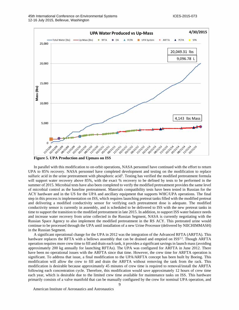
The UPA was initially activated on November 20, 2008. In the last two years, the UPA has produced 2108 L (4648
lb) of distillate at 70 to 75% recovery, cycling through 61 ARFTA cycles during that time. As of April 30, 2015, the
total UPA production on ISS is at 9100 L (20,050 lb) of distillate. A graphical summary of UPA production rate and
upmass required for ISS operations is provided in Figure 5. In the past two years, 2 PCPAs, 4 FCPAs, 1 SPA, 1 DA,
6 brine filters and 1 purge gas filter have been replaced to maintain nominal UPA operations.
The UPA experienced two anomalies in the last year due to excess gas in the system. The first event was in early
2014, when the urine collected in the WHC was not adequately pretreated. This occurred because operating procedures
for WHC allowed the crew to temporarily continue use of the WHC while performing steps to recover from the alarm
stating the pretreatment is insufficient. This procedure was based on the understanding that there was enough residual
pretreatment in the system to maintain microbial and chemical control for a short time, but a sustained period of off-
nominal WHC performance in early 2014 resulted in off-nominal UPA performance that was ultimately traced to
inadequate pretreatment. Insufficient pretreatment allows the pH to rise in the urine while also providing insufficient
oxidizer for microbial control. As a result, excess gas is released during UPA processing due to microbial activity.
The WHC was recovered by flushing it with WPA product water that contained elevated levels of pretreatment to
shock the system. The UPA was recovered by processing urine collected in the Russian Segment ACY that had been
adequately pretreated and then transferred to the US Segment in EDVs. EDVs can be offloaded to the UPA Waste
Tank by using the Russian compressor to push the fluid from the EDV into a T-valve located between WHC and UPA
in Node 3. By processing good quality pretreated urine, the UPA eventually returned to nominal operations. After this
point, based on the existing deficit in the ISS water balance, the UPA continued to nominally process urine collected
in the Russian Segment.
The second anomaly with free gas was in April 2015, when an EDV filled in the WHC was emptied into the UPA
Waste Tank. After the crew stopped the transfer by closing the T-valve and stopping the compressor, the UPA waste
tank quantity continue to increase. Further investigation determined this EDV had been used previously in the WHC
in early 2014 when the pretreatment dosing was inadequate. Though it had been drained, it is now believed there was
residual microbial activity that impacted its subsequent use. Analysis of the transfer and subsequent UPA operation
indicates approximately 25% of the volume transferred from the EDV was actually free gas. This ingested gas impacts
the UPA distillation process, resulting in elevated pressure in the DA. This DA had been operational in the UPA for
5 years and was already showing signs of imminent failure due to gear wear (expected end of life failure condition).
The DA was replaced in May 2015 when system performance continued to degrade. Though system performance did
improve at this point, the vacuum hose between the DA and the purge pump also required replacement due to a
restriction detected by the pressure sensors in this line. Since this plumbing has no active microbial control, it is
believed that the restriction was likely due to the accumulation of biomass coupled with condensation that may have
been caused by the excess free gas still being processed by the system.

45th International Conference on Environmental Systems ICES-2015-073 12-16 July 2015, Bellevue, Washington
American Institute of Aeronautics and Astronautics
8
The UPA experienced multiple failures of the FCPA in the last several years due to various mechanical issues.
S/N 002 failed in September 2011 due to insufficient lubrication of the pump motor bearing at the vendor. This issue
was resolved by adding an inspection step at the vendor to insure adequate lubrication. S/N 001R (reflight of S/N 001)
failed one year later due to a misalignment of the motor adaptor to the motor shaft on the harmonic drive. This
assembly issue was addressed by modifying the procedure and including inspection steps to insure the shaft was
properly aligned. S/N 003 failed in March 2013 after six months of operation due to misalignment of the harmonic
drive and a discrepant snap ring groove, which was also identified as a manufacturing issue for two other FCPAs and
four PCPAs. The snap ring groove was improperly machined by the vendor due to a misinterpretation of the drawing,
and has been resolved for future ORUs. Unfortunately, this error potentially impacted multiple ORUs before it was
detected and resolved. FCPA S/N 004 and 005 both failed early in their operation (5 months for S/N 004 and 10
months for S/N 005), both of which could have been due to either harmonic drive misalignment or the discrepant snap
ring groove. The failure investigation of each of these ORUs is currently underway. Next, S/N 006 failed after 7
months in February 2015 due to a leak of pretreated urine, most likely through a pressure switch in the brine recycle
loop. This ORU has not been returned for evaluation yet, but the UPA engineering team has already decided to
eliminate the pressure switch from the UPA design to eliminate this potential failure mode. Finally, S/N 001R (2nd
reflight) seized after only 41 minutes of operation. This ORU has also not been returned for a failure investigation,
but it is known that the ORU could have a faulty snap ring groove.
This spate of failures to a single ORU has led NASA personnel to question the overall reliability of the FCPA
pump for ISS and future manned missions. NASA is currently developing an upgrade to the drive shaft design that
would replace the harmonic drive with a planetary gear. Though the harmonic drive is considered very reliable once
properly installed, there are multiple opportunities for failure during the assembly and installation process. In contrast,
the planetary gear design supports a robust installation process and is expected to produce a marked increase in on-
orbit reliability of the FCPA.
As reported previously3,4, Distillation Assembly (DA) S/N 02 failed on October 24, 2009 due to accumulation of
solids in the Distillation Assembly. The root cause of the anomaly was due to the precipitation of calcium sulfate in
the urine brine at the target recovery of 85%. Calcium is present in the urine primarily due to bone loss from the crew,
whereas sulfate is present primarily due to the use of sulfuric acid in the urine pretreatment. Calcium levels on ISS are
elevated compared to ground urine due to the absence of gravity. During ground testing, the UPA was proven to have
no issues with recovering 85% of the water from pretreated urine. However, at 85% recovery on ISS, the higher
concentration of calcium resulted in calcium sulfate exceeding its solubility limit. The initial response to this failure
was to reduce the recovery to 70%. In parallel, ISS crew members have been instructed to drink more water primarily
to improve overall health, but also to reduce the calcium concentration in the raw urine. Based on approximately two
years of data, analysis of crew urine has determined that the average calcium concentration has dropped to a level that
will support 75% recovery by the UPA.
45th International Conference on Environmental Systems ICES-2015-073 12-16 July 2015, Bellevue, Washington
American Institute of Aeronautics and Astronautics
9
Figure 5. UPA Production and Upmass on ISS
In parallel with this modification to on-orbit operations, NASA personnel have continued with the effort to return
UPA to 85% recovery. NASA personnel have completed development and testing on the modification to replace
sulfuric acid in the urine pretreatment with phosphoric acid5. Testing has verified the modified pretreatment formula
will support water recovery above 85%, with the exact % recovery to be defined by tests to be performed in the
summer of 2015. Microbial tests have also been completed to verify the modified pretreatment provides the same level
of microbial control as the baseline pretreatment. Materials compatibility tests have been tested in Russian for the
ACY hardware and in the US for the UPA and ancillary equipment that supports WHC/UPA operations. The final
step in this process is implementation on ISS, which requires launching pretreat tanks filled with the modified pretreat
and delivering a modified conductivity sensor for verifying each pretreatment dose is adequate. The modified
conductivity sensor is currently in assembly, and is scheduled to be delivered to ISS with the new pretreat tanks in
time to support the transition to the modified pretreatment in late 2015. In addition, to support ISS water balance needs
and increase water recovery from urine collected in the Russian Segment, NASA is currently negotiating with the
Russian Space Agency to also implement the modified pretreatment in the RS ACY. This pretreated urine would
continue to be processed through the UPA until installation of a new Urine Processor (delivered by NIICHIMMASH)
in the Russian Segment.
A significant operational change for the UPA in 2012 was the integration of the Advanced RFTA (ARFTA). This
hardware replaces the RFTA with a bellows assembly that can be drained and emptied on ISS2,3. Though ARFTA
operation requires more crew time to fill and drain each tank, it provides a significant savings in launch mass (avoiding
approximately 200 kg annually for launching RFTAs). The UPA was configured for ARFTA in June 2012. There
have been no operational issues with the ARFTA since that time. However, the crew time for ARFTA operation is
significant. To address that issue, a final modification to the UPA/ARFTA concept has been built by Boeing. This
modification will allow the crew to fill and drain the ARFTA without removing the tank from the rack. This
modification is desirable because approximately 45 minutes of crew time is required to removal/install the ARFTA
following each concentration cycle. Therefore, this modification would save approximately 12 hours of crew time
each year, which is desirable due to the limited crew time available for maintenance tasks on ISS. This hardware
primarily consists of a valve manifold that can be manually configured by the crew for nominal UPA operation, and

45th International Conference on Environmental Systems ICES-2015-073 12-16 July 2015, Bellevue, Washington
American Institute of Aeronautics and Astronautics
10
for draining and filling the ARFTA. Since this ARFTA valve includes a crew interface on the panel, NASA/Boeing
took advantage of the opportunity to replace both WRS panels. The new panels implement features to reduce acoustic
emissions, since the UPA is a major contributor to the Node 3 acoustics. The new panels also implement improved
door latches that will make it easier for the crew to access WRS2. This new hardware is scheduled to be available on
ISS in late 2015.
VI. Water Processor Assembly Current Status
The WPA was initially activated on November 22, 2008. As of April 21, 2015, the WPA has produced
approximately 22,386 kg (49,353 lb) of product water, including 4,494 kg (9,907 lb) in 2014 and 1,327 kg (2,925 lb)
so far in 2015.
Engineering personnel completed the investigation of the WPA process pump failure from October 2012. After
970 operational days on ISS, the process pump failed to operate when powered at the beginning of a process cycle.
This pump is designed to operate for two years on ISS, but the failure on ISS is not consistent with the expected wear-
out of the pump at end of life. The root cause for this failure was determined to be wear of the key that maintains the
gear position on the idler shaft. Prior to this failure but subsequent to delivery of the pump that failed in 2012, the key
material was switched from 316L stainless steel to stellite, which is a harder material. It is possible this material change
will prevent subsequent failures, though a modification to the key design would ensure this anomaly did not recur.
The impact of DMSD on the WPA treatment process has been discussed previously1-4. The TOC trend detected
by the TOC Analyzer (TOCA) on ISS has occurred in 2010, 2012, 2013, and 2014 (see Figure 6). The WPA product
water has exhibited nominal TOC levels in the past year, though another trend is expected later in 2015 based on the
current understanding of how DMSD passes through the WPA. A detailed review of the fate of DMSD in the WPA is
documented elsewhere7.
Figure 6. ISS WPA Product Water TOC6
DMSD is a common by-product of the degradation of polydimethylsiloxane (PDMS) compounds (also referred to
as siloxanes), which are common compounds present in various products, including caulks, adhesives, lubricants, and
hygiene products. Various PDMS compounds are prevalent on ISS, and analysis of condensate samples from ISS
show that DMSD has been present in the WPA waste water since WPA operations began on ISS. In addition,
approximately 40 mg/L of DMSD has been detected in samples of the MF Bed effluent taken immediately before the
beds were replaced in 2010 and 2012. Following replacement of the MF Beds, samples of the effluent show DMSD
is not present above the detection limit of 0.4 mg/L. These results indicate the MF Beds are initially removing the
DMSD, but eventually the DMSD saturates the adsorbent and ion exchange resin in each bed. Figure 7 provides the
correlation between MF Bed throughput and the product water TOC trend. The DMSD is then fed to the downstream
reactor at a concentration of approximately 40 mg/L. Ground tests with a development reactor indicate the reactor will
oxidize DMSD to a concentration of approximately 10 mg/L in the reactor effluent. If this ground test accurately
represents reactor performance on ISS, the DMSD in the reactor effluent is being initially removed by the Ion
Exchange Bed, given the fact that DMSD has a slight ionic charge. Eventually, the Ion Exchange Bed is saturated

45th International Conference on Environmental Systems ICES-2015-073 12-16 July 2015, Bellevue, Washington
American Institute of Aeronautics and Astronautics
11
with the DMSD, which results in a breakthrough curve consistent with the TOC trend observed from the ISS TOC
Analyzer.
Figure 7. Correlation Between Product Water TOC and MF Bed Throughput
To prevent DMSD from impacting potable water quality, engineering personnel are developing a method to reduce
DMSD concentrations to manageable concentrations in the condensate by removing the siloxanes in the atmosphere.
This removal step would occur prior to each Condensing Heat Exchanger in the US Laboratory Module, Node 2, and
Node 3. A detailed description of the effort to remove the atmospheric siloxanes can be found elsewhere8.
Previous papers2-4 have addressed the issue with increased pressure drop between the waste tank and the Mostly
Liquid Separator (MLS). This anomaly occurred due to growth of biomass in the plumbing between the waste tank
and the MLS, specifically in the two solenoid valves that have smaller clearances than the rest of the nominal
plumbing. In 2010, a filter was installed upstream of the MLS’s inlet solenoid valve to prevent the valve clearances
from the biomass. In March 2011, the Waste Tank solenoid valve was replaced with a flow-through plug, and the
waste water filter was replaced with a fresh filter. Since its installation, the waste water filter has been replaced a total
of 3 times. WPA tank management has also been implemented since 2011 to insure the bellows is cycled over its
nominal range each month. This prevents significant accumulation of biomass growth on the bellows. In addition to
the tank management scheme, a software modification was implemented in April 2013 to flush the waste water filter
and MLS inlet with iodinated water at the end of each process cycle. This action provides additional mitigation against
biological growth by removing nutrients for biological growth and introducing a biocide to retard further growth.
The Microbial Check Valve ORU was replaced in November 2012 as scheduled maintenance. This ORU includes
an iodinated resin to prevent microorganisms from growing into the potable section of the WPA, and a mechanical
check valve to prevent water from the waste tank from flowing into the potable section (which is at a lower pressure
than the waste tank). However, the installed ORU has not performed to expectations on ISS. Analysis of the data by
engineering personnel determined that the mechanical check valve was working intermittently after installation.
Because the Waste Tank is at a slightly higher pressure than the product lines upstream of the 3-way valve in the
reprocess line, waste water can flow upstream when this valve is not checking. Operations personnel were able to
periodically induce the check valve to function by cycling the valves to introduce a pressure drop across the MCV’s
check valve. However, after approximately 6months of operation, this method was no longer successful. To insure
waste water does not reach the potable lines, a WPA Reprocess mode is initiated every 24 hours to flush the reprocess

45th International Conference on Environmental Systems ICES-2015-073 12-16 July 2015, Bellevue, Washington
American Institute of Aeronautics and Astronautics
12
line with potable water. Future MCV ORUs may function as intended since the check valve design was slightly
modified when a new vendor was used to delivery this component. However, the low pressure drop in this application
may prevent a check valve from reliably functioning in this location.
The Gas Separator is showing indications of performance degradation after 5.5 years of use. The Gas Separator’s
ability to maintain temperatures during initial flow started to degrade in early 2014, but the hardware continues to
separate the gas from the 2-phase mixture. The time limit for the temperatures to recover at the start of flow was
increased and the Gas Separator has continued to operate with the degraded performance.
The Particulate Filter was replaced in July 2013 due to increased pressure drop between the process pump and the
Multifiltration Beds. Subsequent data indicated that installation of a new Particulate Filter was only partially
successful in reducing the pressure drop in this region. The other item downstream of the process pump was a check
valve, which was installed prior to initial operation of the WPA in 2008 to prevent overpressurization of the Mostly
Liquid Separator due to specific failure conditions that would remove power to the WPA. The software revision
implemented in April 2013 addressed these failure conditions, allowing the check valve to be removed in January
2014. Subsequent operation of the WPA showed this activity reduced the pressure drop in this region of the WPA to
less than 7 kPa (1 psig).
As noted previously3, the Catalytic Reactor was redesigned in 2010-2011to address the degradation of o-rings after
prolonged exposure to the reactor’s operating temperature. This investigation showed that the o-ring material
developed a compression set that allowed the seal to leak after approximately two years in service. The o-ring material
was replaced with a similar material that did not experience the same magnitude of swell when exposed to water at
the elevated temperature and pressure. Unfortunately, the first Catalytic Reactor to undergo this redesign also
developed a leak on ISS in March 2014 after less than two years of operation on ISS. The failed Catalytic Reactor was
returned to the ground to evaluate the seal life and refurbishment. The seals that were maintained at the elevated
temperature had no life remaining. These seals all had significant leaks at ambient temperature. One of the seals
exposed to elevated temperatures only during process cycles (~20% of operating life) also leaked. During standby,
this seal was in a region of the Catalytic Reactor that would cool down to approximately 93 C (200 F). However, the
seals that were typically maintained at a reduced temperature during Standby were physically in better condition that
those maintained at the elevated temperature continuously. Figure 8 provides a visual comparison of a continuously
hot seal (seal on left) compared to a seal that was at the elevated temperature only 20% of the operating life. This
failure investigation helped substantiate the assumed root cause, which is that the seal material is not compatible with
the elevated process temperatures of the Catalytic Reactor for the planned 5 year life. To improve seal life, engineering
personnel decided to reduce the Catalytic Reactor temperature in Standby to 93 C (200 F) instead of continuously
maintaining it at the nominal temperature of 131 C (267 F). Starting in June of 2014, the Standby temperature for the
reactor was incrementally reduced by 2.8 to 8.3 C (5 to 15 F) every few weeks (to allow analysis of the temperature
change on thermal transients during mode transitions). By February of 2015, the Standby temperature had been
reduced to 96 C (205 F). As of May 2015, the current Catalytic Reactor has been installed for 1 year and 2 months,
and engineering personnel will continue to monitor its performance to determine if the reduction in Standby
temperature will result in increased seal life.

45th International Conference on Environmental Systems ICES-2015-073 12-16 July 2015, Bellevue, Washington
American Institute of Aeronautics and Astronautics
13
Figure 8. Catalytic Reactor Seals
In March 2015 the Reactor Health Sensor conductivity began an increasing trend that eventually exceeded the
setpoint of 50 mhos/cm, resulting in an extended reprocess cycle to recover the WPA ability to deliver potable water.
Potential causes include an increase in the concentration of volatile organics in the humidity condensate, DMSD
breakthrough of the MF Beds, degraded performance of the Catalytic Reactor, degradation of the Gas Separator, or
possibly a combination of these factors. This issue was complicated by the fact that the conductivity continued to
increase to approximately 100 mhos/cm during the extended reprocess cycle, during which the water was recycled
through the system multiple times before the RHS conductivity finally began decreasing. It is unclear why this would
occur, though possibly a volatile organic was introduced at a significant concentration or the reprocess cycle
introduced a pH shift in the reactor effluent. After the RHS conductivity was recovered in reprocess, the system was
first fed only urine distillate, followed by condensate collected before the conductivity excursion. In both cases, the
RHS conductivity remained nominal (<10 mhos/cm). Next, fresh condensate was fed to the WPA, after which the
RHS conductivity rapidly increased. During this trend, the WPA flow rate was reduced from ~5.7 kg/hr (12.5 lb/hr)
to ~5 kg/hr (11 lb/hr) to increase the residence time in the reactor for the oxidation process. The conductivity peaked
shortly thereafter and gradually decreased to nominal levels, though it cannot be concluded this was due to the change
in flow rate or some other unknown effect. Figure 9 shows the RHS trend since the extended reprocess cycle.
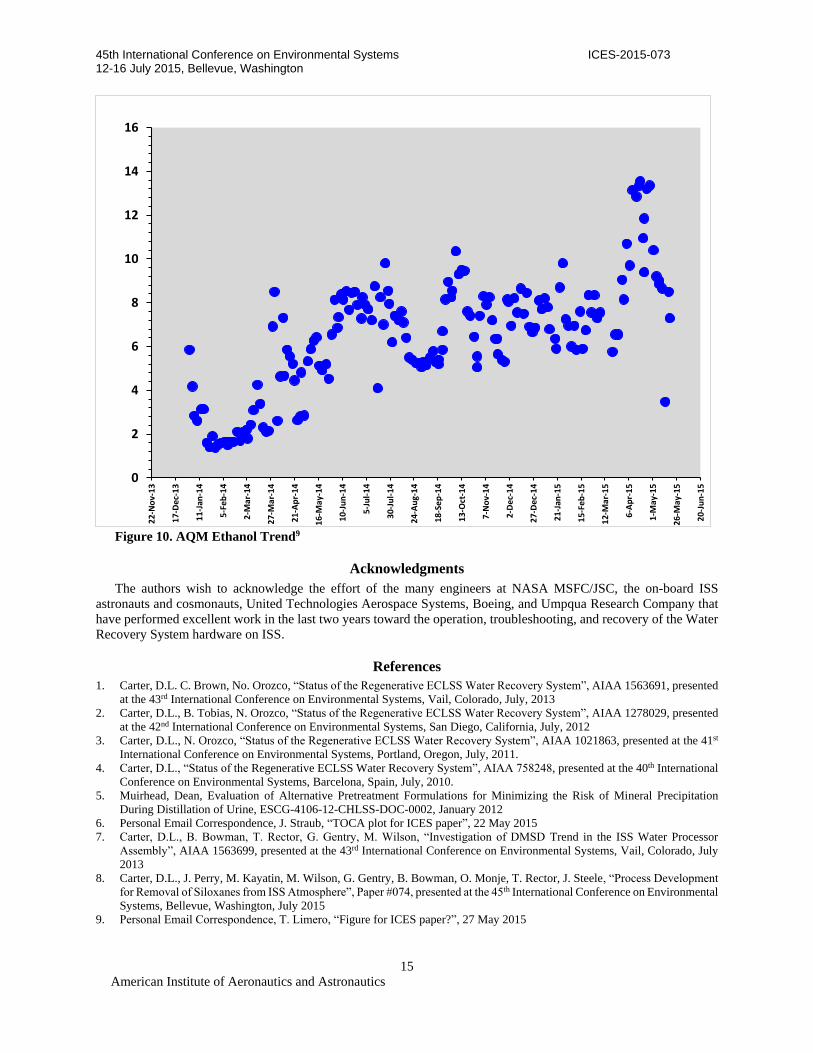
As stated previously, it is possible this trend is due to the increased concentration of volatile organics in the
humidity condensate. The Air Quality Monitor (AQM) has indicated an increase in the ethanol concentration on ISS
since March 2014 from less than 5 mg/m3 to approximately 6 to 10 mg/m3. Figure 10 provide the AQM results for
ethanol since January 2014. This increase is expected to be due to an unknown source of ethanol on ISS. Shortly after
the RHS conductivity excursion in March 2015, the ethanol concentration reported by AQM increased to
approximately 13 mg/m3, though this value is expected to be approximately 30% low because it is above the calibrated
range of the AQM for ethanol. Also, several organics were observed at higher than normal levels in the November
2014 sample of the humidity condensate, primarily including ethanol but also methanol and 1-propanol. In early May,
the ethanol concentration reported by AQM decreased back to approximately 8 to 10 mg/m3 for reasons unknown to
ground personnel. Though the ethanol increase observed in March 2015 occurred after the RHS conductivity increase,
the ethanol decrease in early May occurred approximately at the same time as the RHS conductivity trended down.
This correlation and the elevated ethanol levels will continue to be monitored by ground personnel and addressed as
required to maintain WPA operation.
WPA in

45th International Conference on Environmental Systems ICES-2015-073 12-16 July 2015, Bellevue, Washington
American Institute of Aeronautics and Astronautics
14
Figure 9. RHS Conductivity Trend
VII. Conclusion
In the past two years, the WRS has continued to provide the ISS crew with potable water for drinking, electrolysis
via the Oxygen Generation System, flush water for the Waste & Hygiene Compartment, hygiene water, and payloads.
The UPA has operated at a reduced water recovery of 75% to prevent precipitation of calcium sulfate in the brine.
Though progress has been made toward the goal of returning to 85% recovery, ongoing technology development will
not be ready for implementation on ISS until late 2015. Furthermore, the current water balance on ISS does not require
85% recovery to meet current ISS needs, due to the continuing availability of the WRS, recovery of water from the
RS urine, and the resupply capability of the Progress, HTV, and Commercial vehicles.
The UPA has experienced numerous FCPA failures in the last two years due to various reasons. The root cause
for the drive shaft failures has been addressed with modifications to vendor inspection processes and the assembly
process of the pump at MSFC. The leak in FCPA S/N 006 will likely be addressed by deleting this instrumentation in
future ORUs. Though this ORU has presented significant logistics challenges toward maintaining UPA operation, the
Distillation Assembly and SPA recently replaced operated well beyond their expected service life. Similarly, the Waste
Tank and ARFTA (both bellows tanks) have operated without any performance issues, indicating this hardware is also
viable for long term missions.
In the past two years, the WPA has experienced pressure drop issues leading to the replacement of the Particulate
Filter and removal of the MLS check valve. A recurrence of the Catalytic Reactor seal leak has occurred, and ground
personnel are currently monitoring anomalous Reactor Health Sensor conductivity and a degraded Gas Separator.
Finally, efforts are ongoing to develop a design solution that will prevent DMSD from impacting the nominal MF Bed
replacement schedule.
45th International Conference on Environmental Systems ICES-2015-073 12-16 July 2015, Bellevue, Washington
American Institute of Aeronautics and Astronautics
15
Figure 10. AQM Ethanol Trend9
Acknowledgments
The authors wish to acknowledge the effort of the many engineers at NASA MSFC/JSC, the on-board ISS
astronauts and cosmonauts, United Technologies Aerospace Systems, Boeing, and Umpqua Research Company that
have performed excellent work in the last two years toward the operation, troubleshooting, and recovery of the Water
Recovery System hardware on ISS.
References
1. Carter, D.L. C. Brown, No. Orozco, “Status of the Regenerative ECLSS Water Recovery System”, AIAA 1563691, presented
at the 43rd International Conference on Environmental Systems, Vail, Colorado, July, 2013
2. Carter, D.L., B. Tobias, N. Orozco, “Status of the Regenerative ECLSS Water Recovery System”, AIAA 1278029, presented
at the 42nd International Conference on Environmental Systems, San Diego, California, July, 2012
3. Carter, D.L., N. Orozco, “Status of the Regenerative ECLSS Water Recovery System”, AIAA 1021863, presented at the 41st
International Conference on Environmental Systems, Portland, Oregon, July, 2011.
4. Carter, D.L., “Status of the Regenerative ECLSS Water Recovery System”, AIAA 758248, presented at the 40th International
Conference on Environmental Systems, Barcelona, Spain, July, 2010.
5. Muirhead, Dean, Evaluation of Alternative Pretreatment Formulations for Minimizing the Risk of Mineral Precipitation
During Distillation of Urine, ESCG-4106-12-CHLSS-DOC-0002, January 2012
6. Personal Email Correspondence, J. Straub, “TOCA plot for ICES paper”, 22 May 2015
7. Carter, D.L., B. Bowman, T. Rector, G. Gentry, M. Wilson, “Investigation of DMSD Trend in the ISS Water Processor
Assembly”, AIAA 1563699, presented at the 43rd International Conference on Environmental Systems, Vail, Colorado, July
2013
8. Carter, D.L., J. Perry, M. Kayatin, M. Wilson, G. Gentry, B. Bowman, O. Monje, T. Rector, J. Steele, “Process Development
for Removal of Siloxanes from ISS Atmosphere”, Paper #074, presented at the 45th International Conference on Environmental
Systems, Bellevue, Washington, July 2015
9. Personal Email Correspondence, T. Limero, “Figure for ICES paper?”, 27 May 2015
0
2
4
6
8
10
12
14
16
22-Nov-13
17-Dec-13
11-Jan
-14
5-Feb
-14
2-M
ar-14
27-M
ar-14
21-Apr-14
16-M
ay-14
10-Jun-14
5-Jul-14
30-Jul-14
24-Aug-14
18-Sep-14
13-Oct-14
7-Nov-14
2-Dec-14
27-Dec-14
21-Jan
-15
15-Feb
-15
12-M
ar-15
6-Apr-15
1-M
ay-15
26-M
ay-15
20-Jun-15