Embed Size (px)
Citation preview
Status and Promiseof
CT’s and Magnetized Target Fusion
G. A. Wurden*
Los Alamos National Laboratory
Fusion Power AssociatesGermantownDec. 13, 2004
*With contributions from A. Hoffman (UW) and D. Hill (LLNL)
CT’s: Spheromaks & Field Reversed Configurations
At LLNL, the SSPX experiment is investigating spheromak formation,sustainment, and confinement issues. (Hill, Mclean, Wood, Ryutov).
At UC-Davis, formation and acceleration of spheromaks. (Hwang)
At the U of Washington, field reversed configuration plasmas are studied in boththe TCS (being upgraded) and PHD (under construction) experiments,focusing on RMF sustainment and translation/ballistic compression.(Hoffman and Slough)
At LANL, high density FRC’s are being studied for use as a target plasma inmagnetized target fusion experiments. Plans are underway for plasma/linerimplosion experiments in FY07. (Intrator, Wurden, Degnan)
At PPPL, driven FRC experiment, merging spheromaks, and general FRCtheory. (Cohen, Ji, Yamada, Belova)
At Swarthmore and Caltech, studies of basic plasmas, aimed at astrophysicsand spheromak physics. (Brown, Bellan)
November 2004 APS 2004
SSPX was built to examine energy confinement andmagnetic field generation
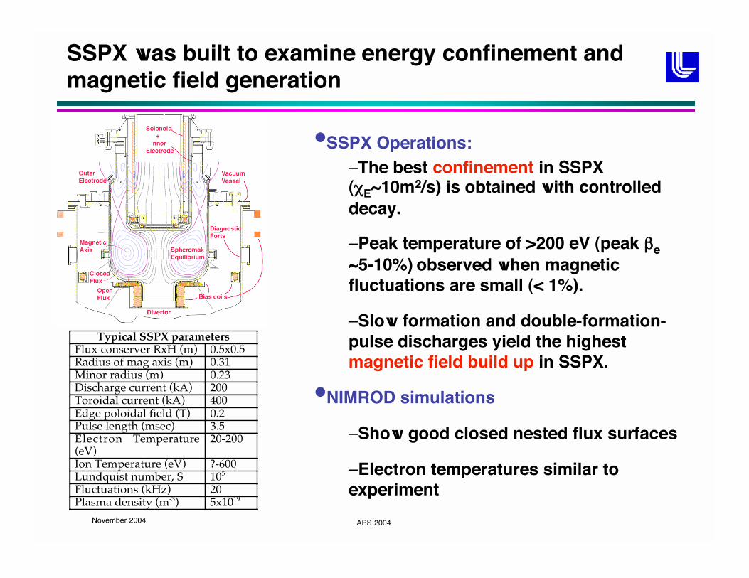
Typical SSPX parametersFlux conserver RxH (m) 0.5x0.5Radius of mag axis (m) 0.31Minor radius (m) 0.23Discharge current (kA) 200Toroidal current (kA) 400Edge poloidal field (T) 0.2Pulse length (msec) 3.5Electron Temperature(eV)
20-200
Ion Temperature (eV) ?-600Lundquist number, S 105
Fluctuations (kHz) 20Plasma density (m-3) 5x10¹⁹
•SSPX Operations:–The best confinement in SSPX( E~10m2/s) is obtained with controlleddecay.
–Peak temperature of >200 eV (peak e~5-10%) observed when magneticfluctuations are small (< 1%).
–Slow formation and double-formation-pulse discharges yield the highestmagnetic field build up in SSPX.
•NIMROD simulations
–Show good closed nested flux surfaces
–Electron temperatures similar toexperiment
November 2004 APS 2004
Summary: We are developing improved understanding of energy
confinement in high-temperature SSPX plasmas
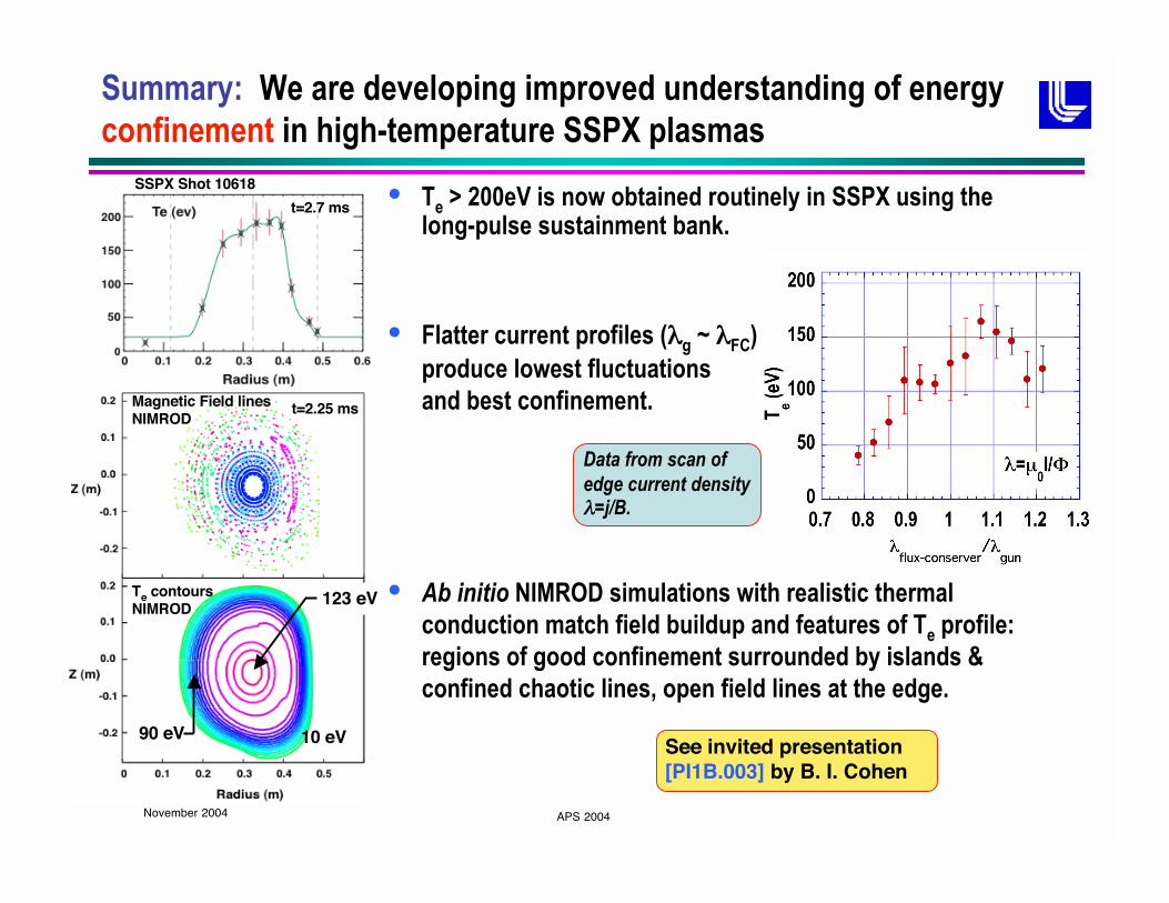
• Te > 200eV is now obtained routinely in SSPX using thelong-pulse sustainment bank.
• Flatter current profiles ( g ~ FC)
produce lowest fluctuations
and best confinement.
• Ab initio NIMROD simulations with realistic thermal
conduction match field buildup and features of Te profile:
regions of good confinement surrounded by islands &
confined chaotic lines, open field lines at the edge.
t=2.7 ms
SSPX Shot 10618
Magnetic Field linesNIMROD
Te contoursNIMROD
t=2.25 ms
123 eV
90 eV 10 eV
Data from scan of
edge current density=j/B.
See invited presentation[PI1B.003] by B. I. Cohen
November 2004 APS 2004
Summary: Participation in NSF Center for Magnetic Self
Organization supports study of magnetic reconnection in SSPX
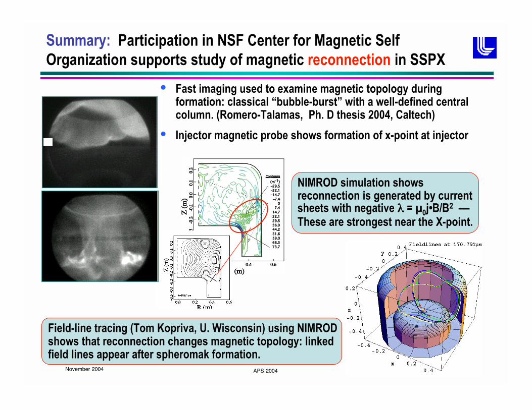
• Fast imaging used to examine magnetic topology duringformation: classical “bubble-burst” with a well-defined centralcolumn. (Romero-Talamas, Ph. D thesis 2004, Caltech)
• Injector magnetic probe shows formation of x-point at injector
NIMROD simulation showsreconnection is generated by currentsheets with negative = 0j•B/B2 ––These are strongest near the X-point.
Field-line tracing (Tom Kopriva, U. Wisconsin) using NIMRODshows that reconnection changes magnetic topology: linkedfield lines appear after spheromak formation.
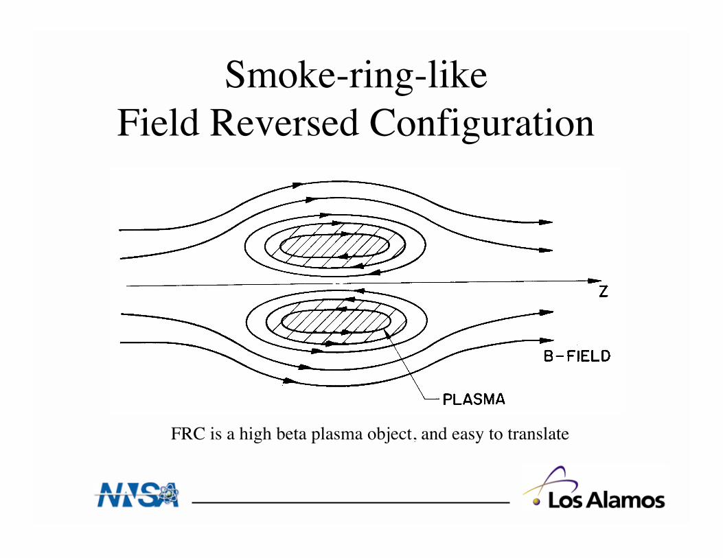
Smoke-ring-likeField Reversed Configuration
FRC is a high beta plasma object, and easy to translate
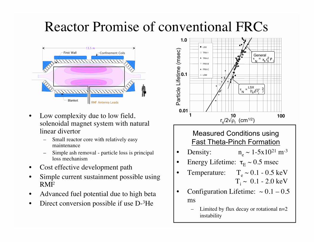
Reactor Promise of conventional FRCs
• Low complexity due to low field,solenoidal magnet system with naturallinear divertor
– Small reactor core with relatively easymaintenance
– Simple ash removal - particle loss is principalloss mechanism
• Cost effective development path• Simple current sustainment possible using
RMF• Advanced fuel potential due to high beta• Direct conversion possible if use D-3He
• Density: ne ~ 1-5x10²¹ m-3
• Energy Lifetime: E ~ 0.5 msec
• Temperature: Te ~ 0.1 - 0.5 keV Ti ~ 0.1 - 2.0 keV
• Configuration Lifetime: ~ 0.1 – 0.5ms
– Limited by flux decay or rotational n=2instability
BlanketRMF Antenna Leads
Confinement CoilsFirst Wall
13.5 m
0.01
0.1
1.0
1 100
LSX
TRX-1
TRX-2
FRX-B
FRX-C
LSM
rs/2 I (cm1/2)
Pa
rtic
le L
ife
tim
e (
mse
c)
General
Nx r /s s i
2
N (r / )
i
3LSX
s
Measured Conditions using
Fast Theta-Pinch Formation
10
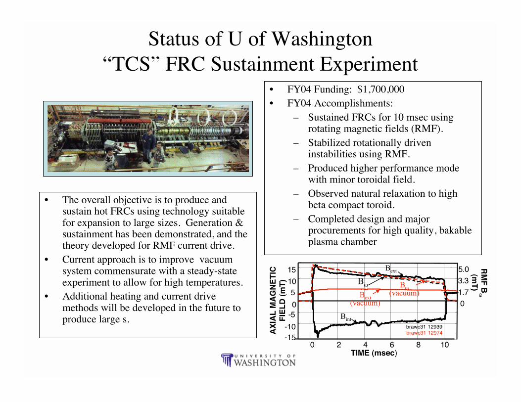
Status of U of Washington“TCS” FRC Sustainment Experiment
• The overall objective is to produce andsustain hot FRCs using technology suitablefor expansion to large sizes. Generation &sustainment has been demonstrated, and thetheory developed for RMF current drive.
• Current approach is to improve vacuumsystem commensurate with a steady-stateexperiment to allow for high temperatures.
• Additional heating and current drivemethods will be developed in the future toproduce large s.
• FY04 Funding: $1,700,000• FY04 Accomplishments:
– Sustained FRCs for 10 msec usingrotating magnetic fields (RMF).
– Stabilized rotationally driveninstabilities using RMF.
– Produced higher performance modewith minor toroidal field.
– Observed natural relaxation to highbeta compact toroid.
– Completed design and majorprocurements for high quality, bakableplasma chamber
TIME (msec)
AX
IAL
MA
GN
ET
ICF
IEL
D (
mT
)
RM
F B
(mT
)
-15-10
0 2 4 6 8 10
-50
510
15
brawc31 12939brawc31 12974
5.03.3
1.70
Bext
Bint
Bext(vacuum)
B B(vacuum)
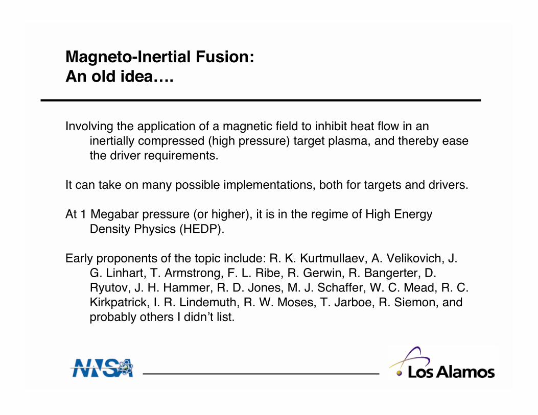
Magneto-Inertial Fusion:An old idea….
Involving the application of a magnetic field to inhibit heat flow in aninertially compressed (high pressure) target plasma, and thereby easethe driver requirements.
It can take on many possible implementations, both for targets and drivers.
At 1 Megabar pressure (or higher), it is in the regime of High EnergyDensity Physics (HEDP).
Early proponents of the topic include: R. K. Kurtmullaev, A. Velikovich, J.G. Linhart, T. Armstrong, F. L. Ribe, R. Gerwin, R. Bangerter, D.Ryutov, J. H. Hammer, R. D. Jones, M. J. Schaffer, W. C. Mead, R. C.Kirkpatrick, I. R. Lindemuth, R. W. Moses, T. Jarboe, R. Siemon, andprobably others I didn’t list.
Definition of Magnetized Target Fusion
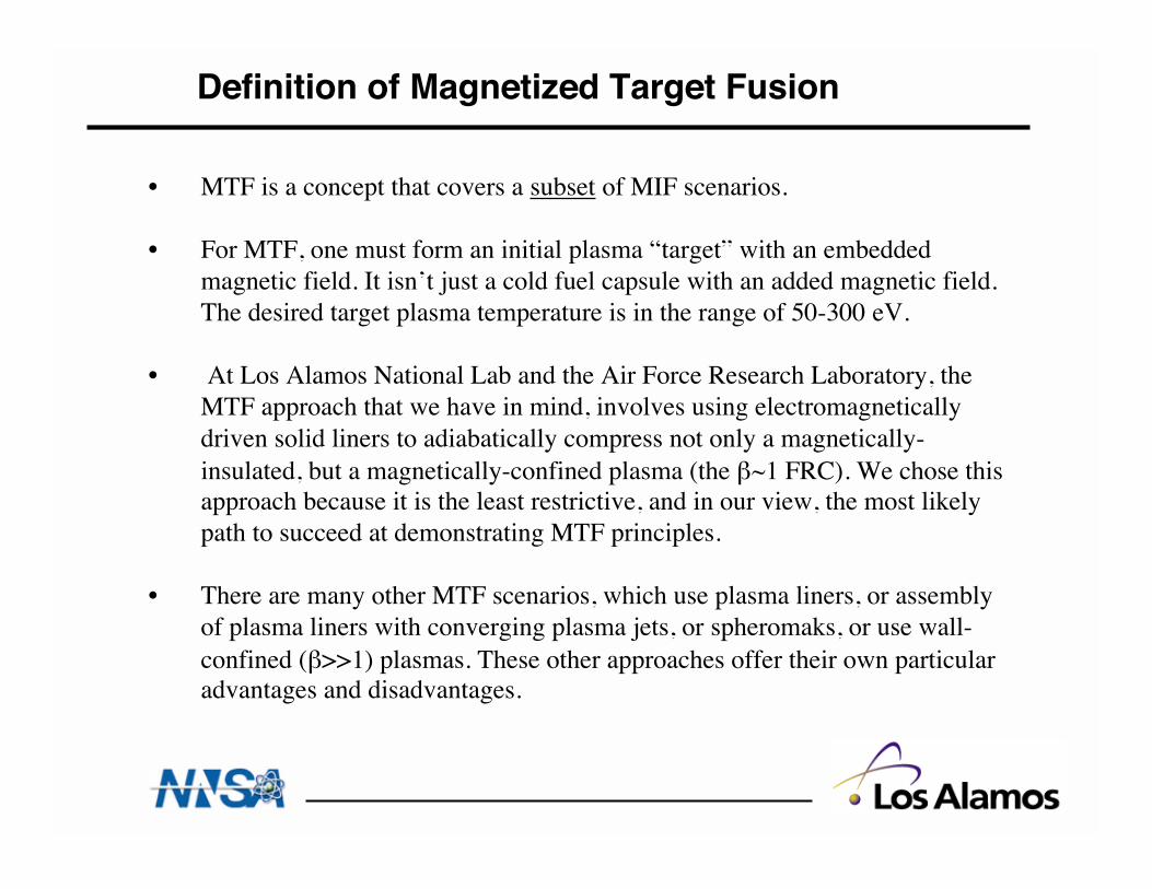
• MTF is a concept that covers a subset of MIF scenarios.
• For MTF, one must form an initial plasma “target” with an embeddedmagnetic field. It isn’t just a cold fuel capsule with an added magnetic field.The desired target plasma temperature is in the range of 50-300 eV.
• At Los Alamos National Lab and the Air Force Research Laboratory, theMTF approach that we have in mind, involves using electromagneticallydriven solid liners to adiabatically compress not only a magnetically-insulated, but a magnetically-confined plasma (the ~1 FRC). We chose thisapproach because it is the least restrictive, and in our view, the most likelypath to succeed at demonstrating MTF principles.
• There are many other MTF scenarios, which use plasma liners, or assemblyof plasma liners with converging plasma jets, or spheromaks, or use wall-confined ( >>1) plasmas. These other approaches offer their own particularadvantages and disadvantages.
Low, Medium, and High Pressure MTF Regimes
• Low pressure (< 10 kbar), resembling LINUS or UCBerkeley compression of a spheromak, which allows forminimum damage to equipment on each pulse
• Medium pressure (0.01-10 Megabar) is appropriate forelectromagnetically driven solid metal liners (the approachwe chose for MTF). Batch burn.
• High pressure (> 10 Megabar) resembles conditions closerto inertial fusion conditions, in Z or heavy ion drivers.Advantage of the possibility of burning cold fuel, forhigher yields.
Special issues associated with MIF
• Required _R of target is lower than with ICF (because the B-fieldhelps)
• Compare slowing down time of alphas relative to configurationlifetime. If BR> 0.3 MGauss-cm, then thermonuclear self-heating canoccur.
• Target symmetry is strongly affected by presence of a magnetic field
• The lower density burn regimes of MIF are in “batch burn mode”, withfractional burn-up of only a few %, and gains are less than ~ 20.
• High-end density regimes for MIF should be able to burn cold fuel atthe boundary.
• There may be more materials near the center of the chamber (due toliner and leads), and therefore there are associated issues with (non-plasma, non-radiation) blast debris.
• Cost of replacement parts relative to value of energy produced.
• Standoff from the location of fusion burn.
• Rep-rating a bigger absolute yield, but at a lower frequency (~0.1Hertz). Lifetime of the pulsed-power driver elements.
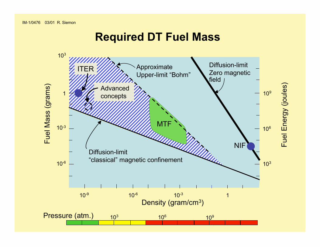
Diffusion determines mass103
Required DT Fuel Mass
Density (gram/cm3)
1
10-3
10-6
10-9 10-6 10-3 1
Fuel M
ass (
gra
ms)
Diffusion-limit
Zero magneticfield
NIF
Approximate
Upper-limit “Bohm”
Advanced
concepts
ITER
Diffusion-limit
“classical” magnetic confinement
IM-1/0476 03/01 R. Siemon
MTF
Fuel E
nerg
y (
joule
s)
106
109
103
106103 109Pressure (atm.)
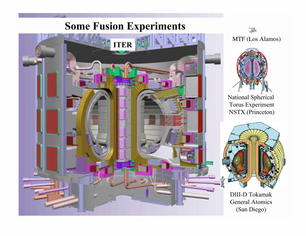
DIII-D Tokamak
General Atomics
(San Diego)
National Spherical
Torus Experiment
NSTX (Princeton)
Some Fusion Experiments
ITERMTF (Los Alamos)
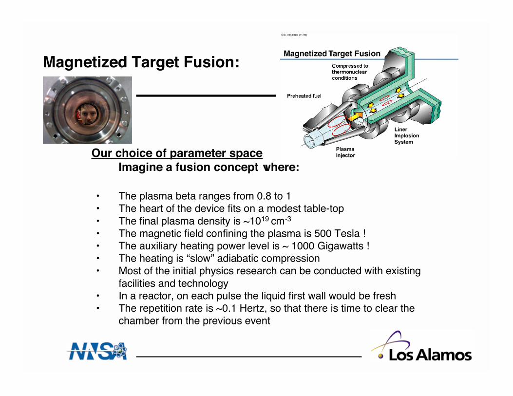
Magnetized Target Fusion:
Our choice of parameter space Imagine a fusion concept where:
• The plasma beta ranges from 0.8 to 1• The heart of the device fits on a modest table-top• The final plasma density is ~1019 cm-3
• The magnetic field confining the plasma is 500 Tesla !• The auxiliary heating power level is ~ 1000 Gigawatts !• The heating is “slow” adiabatic compression• Most of the initial physics research can be conducted with existing
facilities and technology• In a reactor, on each pulse the liquid first wall would be fresh• The repetition rate is ~0.1 Hertz, so that there is time to clear the
chamber from the previous event
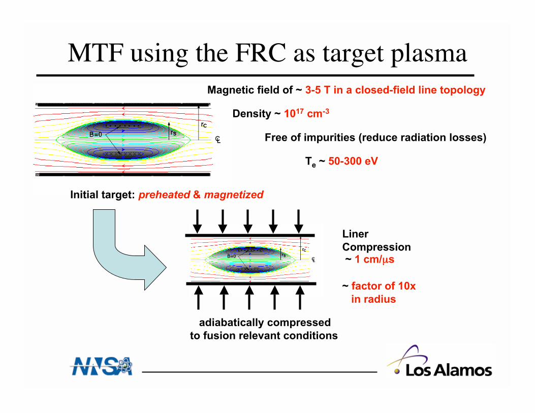
MTF using the FRC as target plasma
adiabatically compressed
to fusion relevant conditions
Liner
Compression ~ 1 cm/µs
~ factor of 10x
in radius
Initial target: preheated & magnetized
Density ~ 1017 cm-3
Free of impurities (reduce radiation losses)
Te ~ 50-300 eV
Magnetic field of ~ 3-5 T in a closed-field line topology
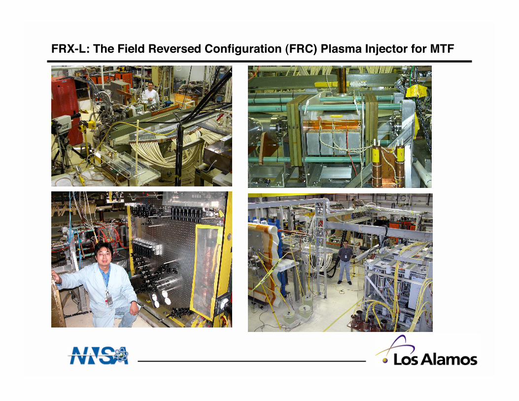
FRX-L: The Field Reversed Configuration (FRC) Plasma Injector for MTF
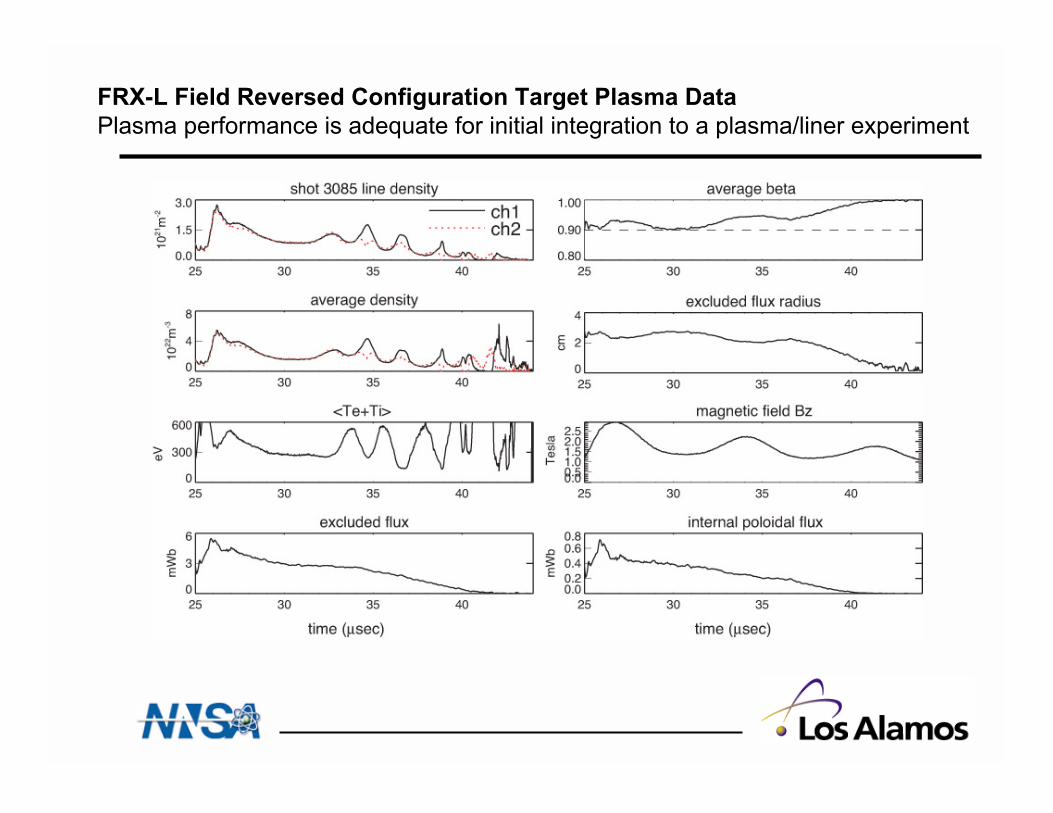
FRX-L Field Reversed Configuration Target Plasma Data
Plasma performance is adequate for initial integration to a plasma/liner experiment
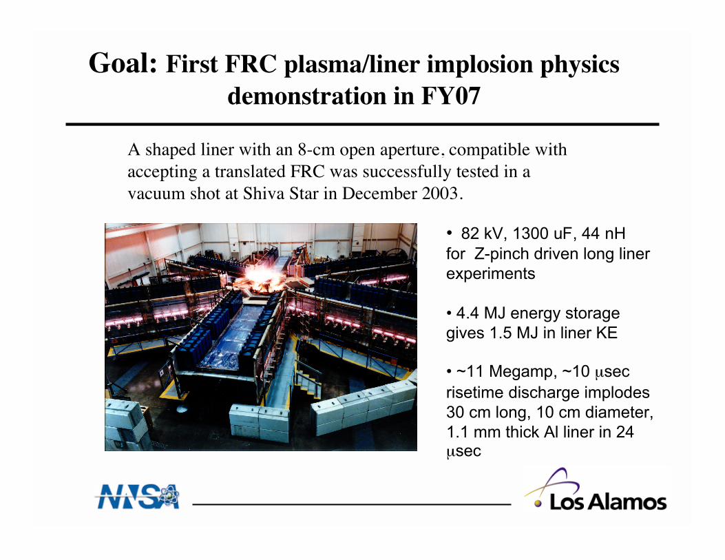
Goal: First FRC plasma/liner implosion physicsdemonstration in FY07
• 82 kV, 1300 uF, 44 nH
for Z-pinch driven long liner
experiments
• 4.4 MJ energy storage
gives 1.5 MJ in liner KE
• ~11 Megamp, ~10 µsec
risetime discharge implodes
30 cm long, 10 cm diameter,
1.1 mm thick Al liner in 24µsec
A shaped liner with an 8-cm open aperture, compatible withaccepting a translated FRC was successfully tested in avacuum shot at Shiva Star in December 2003.
Magnetized Target Fusion:Reference Materials
• Our web pages: http://fusionenergy.lanl.gov andhttp://wsx.lanl.gov
• “Amplification of magnetic fields and heating of plasma by acollapsing metallic shell”, by Linhart, Knoepfel, andGourlain, Nuclear Fusion, CN-10/11, supl. Pt. 2, 733 (1962).
• “Why Magnetized Target Fusion Offers a Low-CostDevelopment Path for Fusion Energy”, by Siemon,Lindemuth, and Schoenberg, Comments Plasma Phys.Controlled Fusion, Vol 18, No. 6, pg 363-386 (1999).
• “Scaling Relations for High-Gain Magnetized Target FusionSystems”, by D. C. Barnes, Comments Plasma Phys.Controlled Fusion, Vol 18, No. 2, pg 71-84 (1997).
• “Magnetized Target Fusion: An Overview”, by R. C.Kirkpatrick, I. R. Lindemuth, M. S. Ward, FusionTechnology, Vol 27, pg 201 (1995).