Embed Size (px)
Citation preview
1
2012. 9. 20
Ji-Ho Jang,
on behalf of the project team
PEFP, KAERI
2012. 9. 20
Ji-Ho Jang,
on behalf of the project team
PEFP, KAERI
Status and Beam Commissioning Plan of PEFP 100-MeV Proton Linac
Status and Beam Commissioning Plan of PEFP 100-MeV Proton Linac
HB2012, Beijing, China
2
Contents
Introduction
Present Status of Proton Engineering Frontier Project Accelerator Development Construction and Installation Status
Commissioning Plan
Summary
3
Introduction
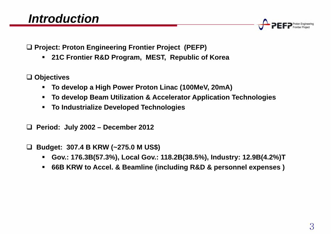
Project: Proton Engineering Frontier Project (PEFP) 21C Frontier R&D Program, MEST, Republic of Korea
Objectives To develop a High Power Proton Linac (100MeV, 20mA) To develop Beam Utilization & Accelerator Application Technologies To Industrialize Developed Technologies
Period: July 2002 – December 2012
Budget: 307.4 B KRW (~275.0 M US$) Gov.: 176.3B(57.3%), Local Gov.: 118.2B(38.5%), Industry: 12.9B(4.2%)T 66B KRW to Accel. & Beamline (including R&D & personnel expenses )
4
Project Site : Gyeongju
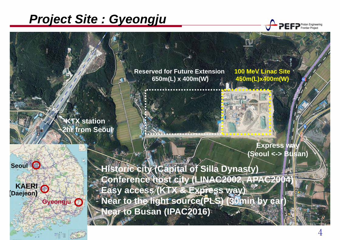
100 MeV Linac Site450m(L)x400m(W)
Reserved for Future Extension 650m(L) x 400m(W)
KTX station~2hr from Seoul
Express way(Seoul <-> Busan)
Seoul
KAERI (Daejeon)
Gyeongju
- Historic city (Capital of Silla Dynasty)- Conference host city (LINAC2002, APAC2004)- Easy access (KTX & Express way)- Near to the light source(PLS) (30min by car)- Near to Busan (IPAC2016)
5
Site Plan
②
③④
⑨
⑩
⑪
⑤
⑥ ⑦
①
⑫
⑧
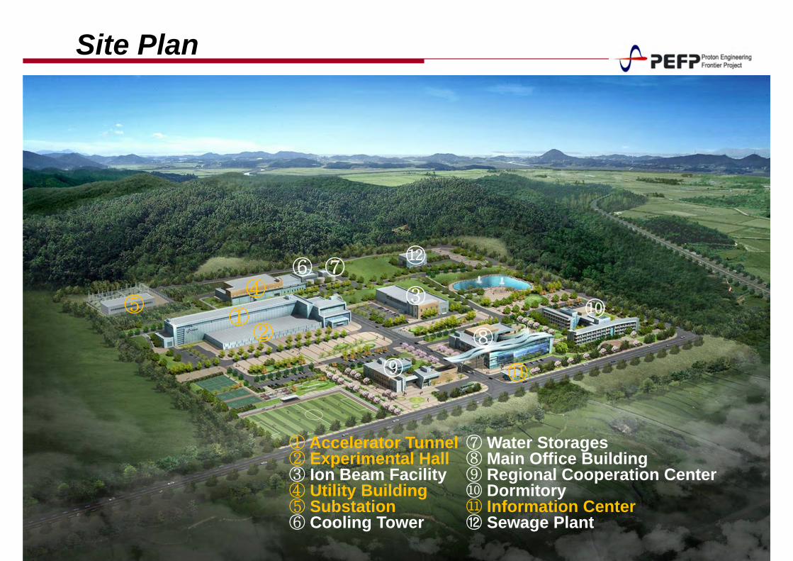
⑦ Water Storages⑧ Main Office Building⑨ Regional Cooperation Center⑩ Dormitory⑪ Information Center⑫ Sewage Plant
① Accelerator Tunnel② Experimental Hall③ Ion Beam Facility④ Utility Building⑤ Substation ⑥ Cooling Tower
6
Accelerator TunnelKlystron gallery
Modulator room
100-MeV Beam lines 20-MeV Beam lines
RFQ20-MeV DTL100-MeV DTL
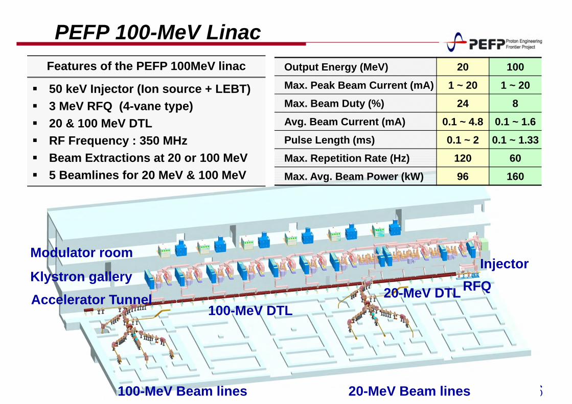
PEFP 100-MeV LinacOutput Energy (MeV) 20 100
Max. Peak Beam Current (mA) 1 ~ 20 1 ~ 20Max. Beam Duty (%) 24 8
Avg. Beam Current (mA) 0.1 ~ 4.8 0.1 ~ 1.6
Pulse Length (ms) 0.1 ~ 2 0.1 ~ 1.33Max. Repetition Rate (Hz) 120 60
Max. Avg. Beam Power (kW) 96 160
Features of the PEFP 100MeV linac
50 keV Injector (Ion source + LEBT) 3 MeV RFQ (4-vane type) 20 & 100 MeV DTL RF Frequency : 350 MHz Beam Extractions at 20 or 100 MeV 5 Beamlines for 20 MeV & 100 MeV
Injector
7
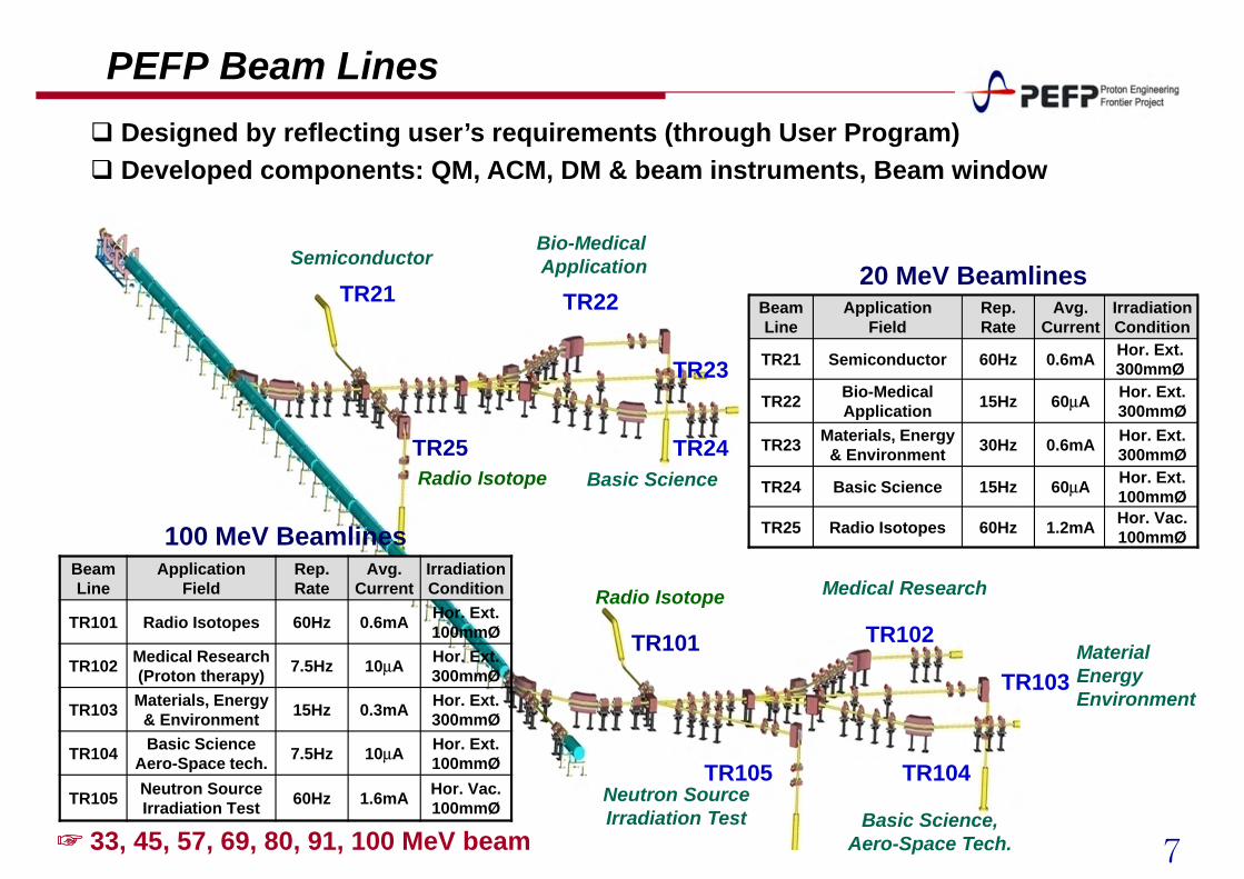
TR25
TR21 TR22
TR23
TR24
TR105
TR101 TR102
TR103
TR104
IrradiationCondition
Avg. Current
Rep.Rate
ApplicationField
BeamLine
Radio Isotopes
Basic Science
Materials, Energy & Environment
Bio-Medical Application
Semiconductor
Hor. Ext.100mmØ60µA15HzTR24
Hor. Ext.300mmØ0.6mA30HzTR23
Hor. Vac.100mmØ1.2mA60HzTR25
Hor. Ext.300mmØ60µA15HzTR22
Hor. Ext. 300mmØ0.6mA60Hz TR21
20 MeV Beamlines
100 MeV BeamlinesBeam Line
ApplicationField
Rep. Rate
Avg. Current
Irradiation Condition
TR101 Radio Isotopes 60Hz 0.6mA Hor. Ext.100mmØ
TR102 Medical Research(Proton therapy) 7.5Hz 10µA Hor. Ext.
300mmØ
TR103 Materials, Energy & Environment 15Hz 0.3mA Hor. Ext.
300mmØ
TR104 Basic ScienceAero-Space tech. 7.5Hz 10µA Hor. Ext.
100mmØ
TR105 Neutron SourceIrradiation Test 60Hz 1.6mA Hor. Vac.
100mmØ
☞ 33, 45, 57, 69, 80, 91, 100 MeV beam
SemiconductorBio-Medical Application
Radio Isotope Basic Science
Basic Science,Aero-Space Tech.
Neutron SourceIrradiation Test
Medical Research
MaterialEnergyEnvironment
Radio Isotope
Designed by reflecting user’s requirements (through User Program) Developed components: QM, ACM, DM & beam instruments, Beam window
PEFP Beam Lines
8
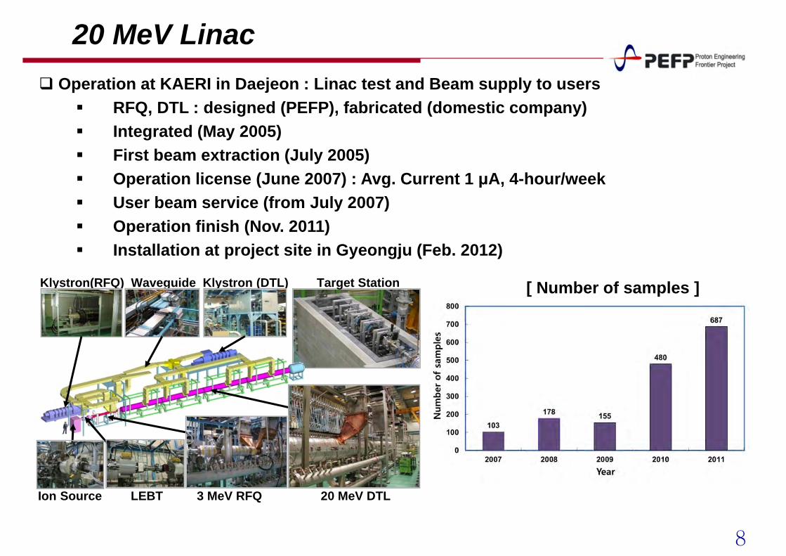
20 MeV Linac Operation at KAERI in Daejeon : Linac test and Beam supply to users
RFQ, DTL : designed (PEFP), fabricated (domestic company) Integrated (May 2005) First beam extraction (July 2005) Operation license (June 2007) : Avg. Current 1 μA, 4-hour/week User beam service (from July 2007) Operation finish (Nov. 2011) Installation at project site in Gyeongju (Feb. 2012)
Waveguide Klystron (DTL)
LEBT 3 MeV RFQIon Source 20 MeV DTL
Klystron(RFQ) Target Station [ Number of samples ]
9
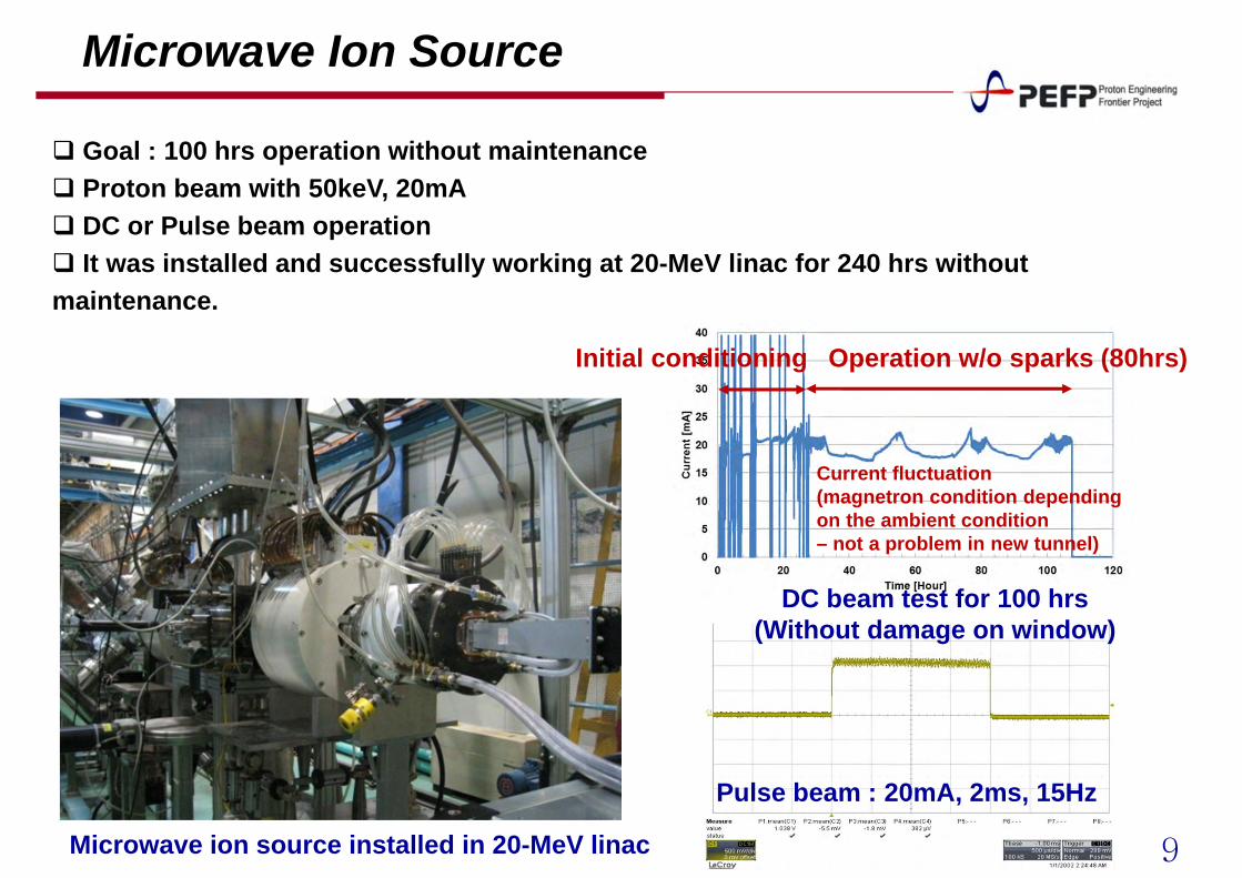
Microwave Ion Source
Pulse beam : 20mA, 2ms, 15Hz
DC beam test for 100 hrs(Without damage on window)
Initial conditioning Operation w/o sparks (80hrs)
Microwave ion source installed in 20-MeV linac
Current fluctuation(magnetron condition depending on the ambient condition – not a problem in new tunnel)
Goal : 100 hrs operation without maintenance Proton beam with 50keV, 20mA DC or Pulse beam operation It was installed and successfully working at 20-MeV linac for 240 hrs without maintenance.
10
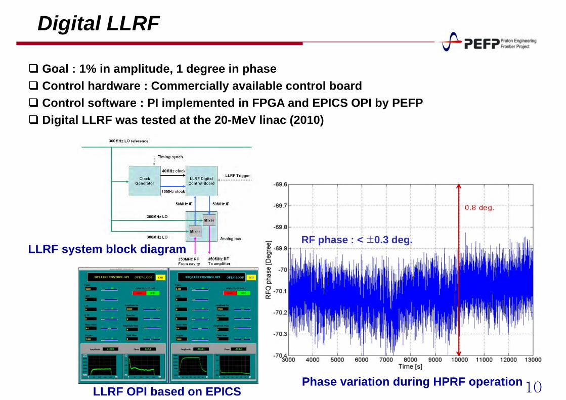
Digital LLRF
RF phase : < ±0.3 deg.LLRF system block diagram
Phase variation during HPRF operationLLRF OPI based on EPICS
Goal : 1% in amplitude, 1 degree in phase Control hardware : Commercially available control board Control software : PI implemented in FPGA and EPICS OPI by PEFP Digital LLRF was tested at the 20-MeV linac (2010)
11
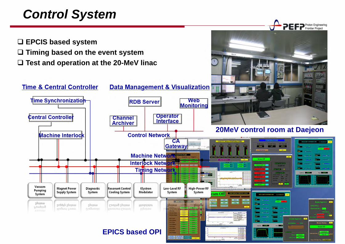
Control System
20MeV control room at Daejeon
EPICS based OPI
EPCIS based system Timing based on the event system Test and operation at the 20-MeV linac
12
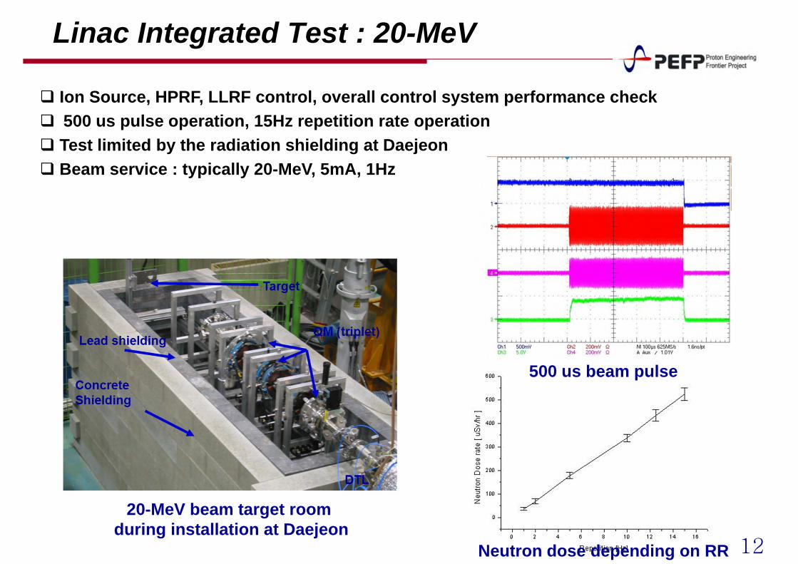
Linac Integrated Test : 20-MeV
20-MeV beam target room during installation at Daejeon
500 us beam pulse
Neutron dose depending on RR
Ion Source, HPRF, LLRF control, overall control system performance check 500 us pulse operation, 15Hz repetition rate operation Test limited by the radiation shielding at Daejeon Beam service : typically 20-MeV, 5mA, 1Hz
13
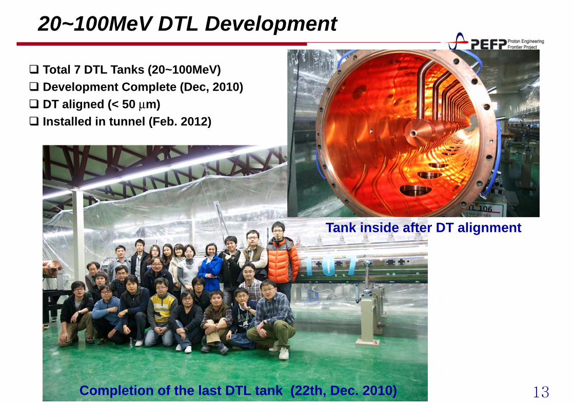
20~100MeV DTL Development
Completion of the last DTL tank (22th, Dec. 2010)
Tank inside after DT alignment
Total 7 DTL Tanks (20~100MeV) Development Complete (Dec, 2010) DT aligned (< 50 µm) Installed in tunnel (Feb. 2012)
14
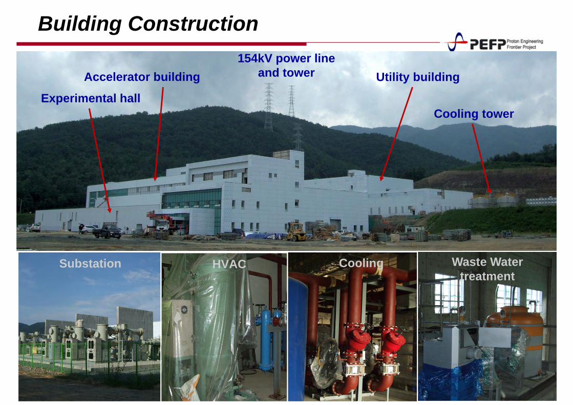
Building Construction
HVACSubstation Cooling Waste Watertreatment
Accelerator building
Experimental hall
Utility building
Cooling tower
154kV power line and tower
15
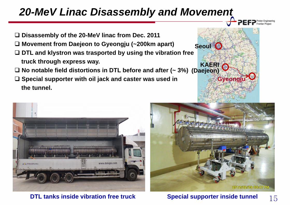
20-MeV Linac Disassembly and Movement
Seoul
KAERI (Daejeon)
Gyeongju
DTL tanks inside vibration free truck Special supporter inside tunnel
Disassembly of the 20-MeV linac from Dec. 2011 Movement from Daejeon to Gyeongju (~200km apart) DTL and klystron was trasported by using the vibration free
truck through express way. No notable field distortions in DTL before and after (~ 3%) Special supporter with oil jack and caster was used in
the tunnel.
16
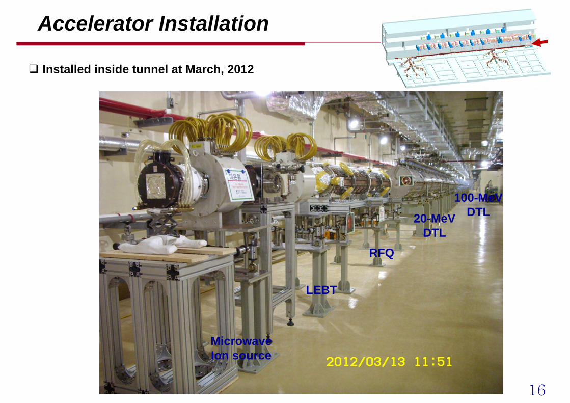
Accelerator Installation
MicrowaveIon source
LEBT
RFQ
20-MeVDTL
100-MeVDTL
Installed inside tunnel at March, 2012
17
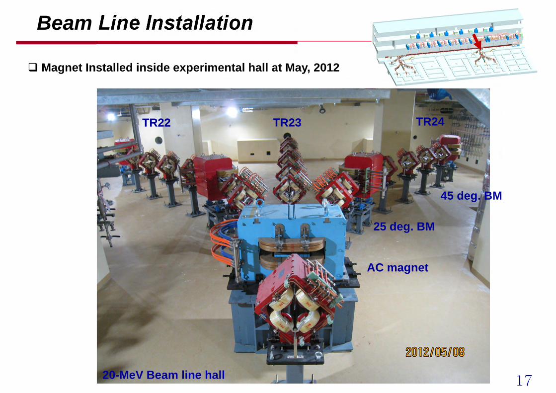
Beam Line Installation
AC magnet
45 deg. BM
TR22
25 deg. BM
TR23 TR24
20-MeV Beam line hall
Magnet Installed inside experimental hall at May, 2012
18
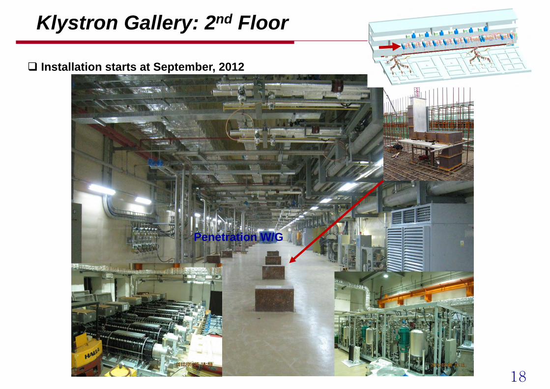
Klystron Gallery: 2nd Floor
Penetration W/G
Utility electrical panel
Installation starts at September, 2012
19
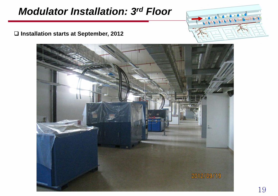
Modulator Installation: 3rd Floor
Installation starts at September, 2012
20
Commissioning Plan
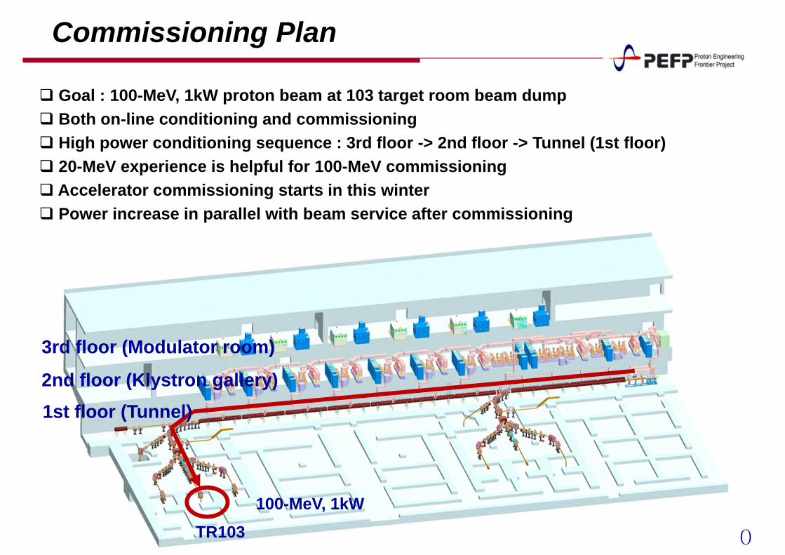
TR103
1st floor (Tunnel)2nd floor (Klystron gallery)
3rd floor (Modulator room)
100-MeV, 1kW
Goal : 100-MeV, 1kW proton beam at 103 target room beam dump Both on-line conditioning and commissioning High power conditioning sequence : 3rd floor -> 2nd floor -> Tunnel (1st floor) 20-MeV experience is helpful for 100-MeV commissioning Accelerator commissioning starts in this winter Power increase in parallel with beam service after commissioning
21
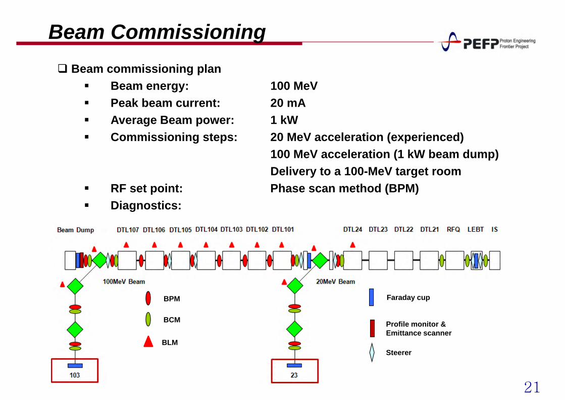
Beam Commissioning Beam commissioning plan
Beam energy: 100 MeV Peak beam current: 20 mA Average Beam power: 1 kW Commissioning steps: 20 MeV acceleration (experienced)
100 MeV acceleration (1 kW beam dump)Delivery to a 100-MeV target room
RF set point: Phase scan method (BPM) Diagnostics:
BPM
BCM
Faraday cup
Profile monitor &Emittance scanner
BLMSteerer
22
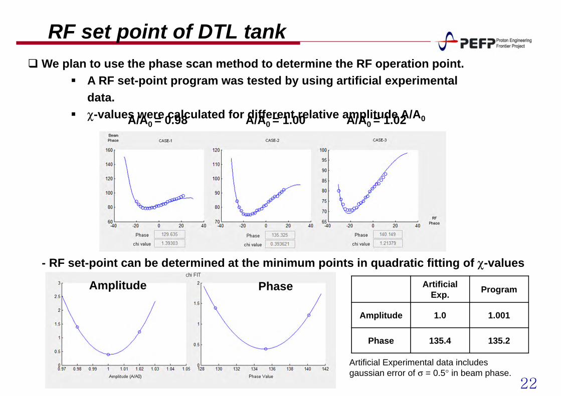
RF set point of DTL tankWe plan to use the phase scan method to determine the RF operation point.
A RF set-point program was tested by using artificial experimental data.
χ-values were calculated for different relative amplitude A/A0A/A0 = 0.98 A/A0 = 1.00 A/A0 = 1.02
- RF set-point can be determined at the minimum points in quadratic fitting of χ-values Artificial
Exp. Program
Amplitude 1.0 1.001
Phase 135.4 135.2
Artificial Experimental data includes gaussian error of σ = 0.5° in beam phase.
Amplitude Phase
23
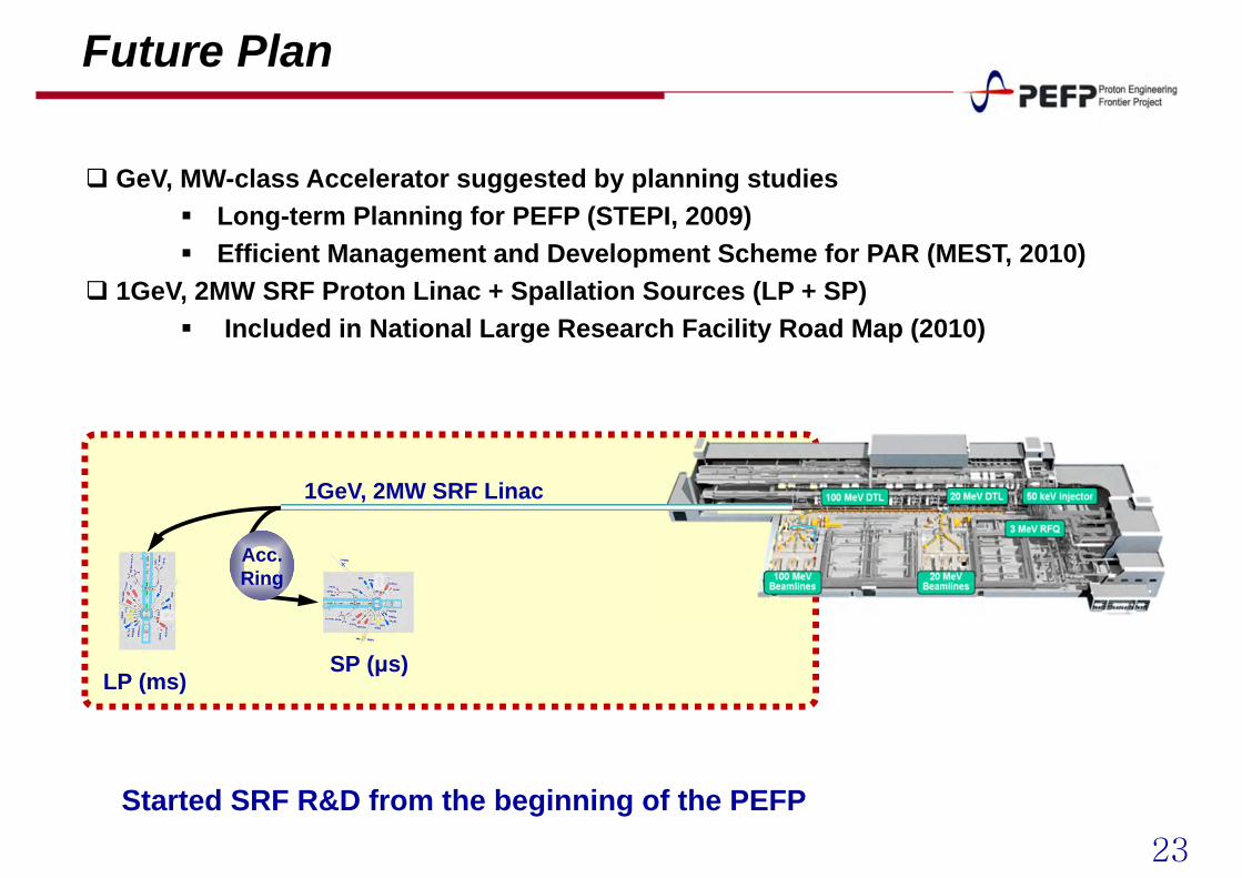
Future Plan
1GeV, 2MW SRF Linac
LP (ms) SP (μs)
Acc.Ring
Started SRF R&D from the beginning of the PEFP
GeV, MW-class Accelerator suggested by planning studies Long-term Planning for PEFP (STEPI, 2009) Efficient Management and Development Scheme for PAR (MEST, 2010)
1GeV, 2MW SRF Proton Linac + Spallation Sources (LP + SP) Included in National Large Research Facility Road Map (2010)
24
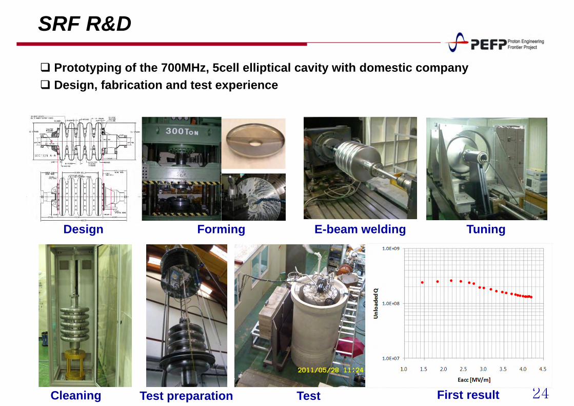
SRF R&D
Design Forming E-beam welding Tuning
Cleaning Test preparation Test First result
Prototyping of the 700MHz, 5cell elliptical cavity with domestic company Design, fabrication and test experience
25
Summary
PEFP Linac and beam lines Injector, 3 MeV RFQ, 100 MeV DTL, 10 beam lines Developed the linac technologies through this project.
20 MeV linac 5 year operation gives us experience on installation, commissioning, and
operation of the proton linac. Test beam line: supplying proton beams to users
Linac and beam line magnet installation: completed 20 MeV part: disintegrated, moved and installed at project site in Gyeongju 20 ~ 100 MeV part, beam line magnet: fabrication, tested and installed
Commissioning HPRF installation started in September 2012 Commissioning will start in this winter Beam service will start in spring 2013
26
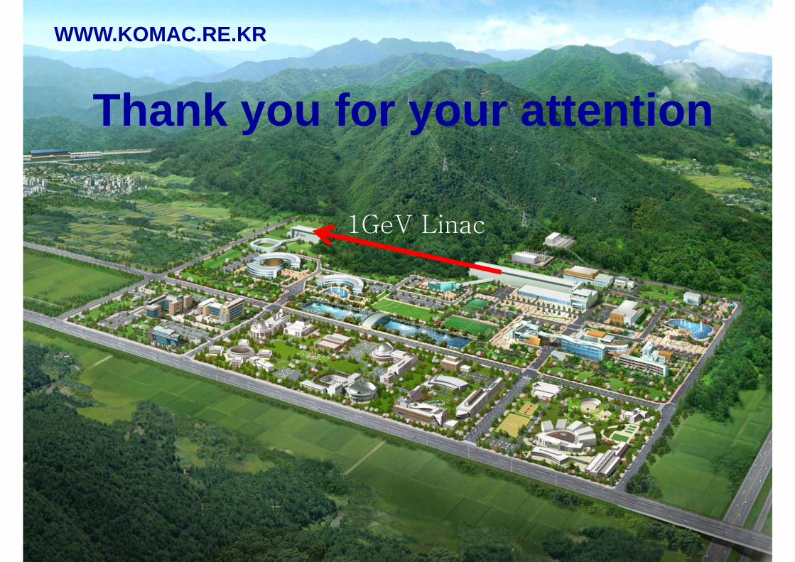
Thank you for your attention
WWW.KOMAC.RE.KR
1GeV Linac

![Activation Products in Proton Therapyindico.ictp.it/event/a06223/session/17/contribution/9/... · 2014. 5. 5. · Proton energy [MeV] Cross section [ μ b ] Formation of 22,24Na in](https://img.pdfslide.us/doc/110x75/610980b874057e6c0b1c4f56/activation-products-in-proton-2014-5-5-proton-energy-mev-cross-section-.jpg)