Embed Size (px)
Citation preview

Journal of ELECTRICAL ENGINEERING, VOL. 55, NO. 5-6, 2004, 122–130
STATOR CURRENT ANALYSIS OF INCIPIENTFAULT INTO ASYNCHRONOUS MOTOR ROTOR
BARS USING FOURIER FAST TRANSFORM
Arezki Menacer∗— Mohamed-Saıd Naıt-Saıd
∗∗
A/Hamid Benakcha∗— Saıd Drid
∗∗
Recently, research has picked up a fervent place in the area of fault diagnosis of electrical machines. Like adjustable
speed drives, fault prognosis has become almost indispensable. Motor current signature analysis is a condition monitoring
technique that is now widely used to diagnose problems such as rotor bars broken, abnormal levels of air gap eccentricity,
shorted turns in low voltage stator windings, and some mechanical problems.
This paper presents the effect of the broken bar time evolution since the created incipient fault on the various character-
istics of the induction machine such as torque, speed and current. This one is simulated while the rotor bar resistance may
be varied linearly versus time since its normal value to the final broken bar situation (partial to total broken bar). In this
way we can observe the incipient fault impact on the different characteristics of the machine quantities (torque, speed andcurrent).
K e y w o r d s: fault simulation, mathematical models, condition monitoring, asynchronous (induction) motors, incipient
broken bar, resistance bar, resistance time ratio
1 INTRODUCTION
The problem of diagnosis is indeed related to that of
the maintenance, utilizing economic factors that are dif-
ficult to evaluate. The issues of preventive and condition-
based maintenance, online monitoring, system fault de-
tection, diagnosis, and prognosis are of increasing impor-
tance.
The key issues for a successful motor operation are
a quality motor, understanding its application, choice of
the proper one for the application, and its proper main-
tenance. The use of induction motors in today’s industry
is extensive and they can be exposed to different hostile
environments, manufacturing defects, etc [1].
The problem of the broken bars in the induction mo-
tors of offshore oilrig pumping stations, which were the
first research tasks of diagnosis, is a good example [2].
Several works followed in the same way [3-6], or initiated
in the diagnosis of other failures of the machine like the
eccentricity of the rotor [7], the open circuits [8], [9], [5],
the wear of the stages [10], [11]. These types of faults usu-
ally refer to the gradual deterioration of the motor that
can lead to motor failure if undetected [1]. Monitoring of
the current per phase can provide indications on the mo-
tors state. This is preferable, compared to other methods
since it is easy for physical measurement. The fault affects
the spectrum current signal while the induction machine
is sufficiently loaded and generally we can extract from
that the number of the broken bars [6].
The motor current based fault detection relies on in-terpretation of the frequency components in the currentspectrum that are related to rotor asymmetries. In or-der to study the phenomena taking place in the rotor, wemodel it in the form of NR mesh as shown in Fig. 1 [14].
2 INDUCTANCES IN INDUCTION MOTORS
The model assumptions are:
• negligible saturation and skin effect,
• uniform air-gap,
• sinusoidal mmf of stator windings in air-gap,
• rotor bars are insulated from the rotor, thus no inter-bar current flows through the laminations,
• relative permeability of machine armatures is assumedinfinite.
Although a sinusoidal mmf of the stator winding isassumed, other winding distributions could also be ana-lyzed by simply using superposition. This is justified bythe fact that different space harmonic components do notinteract [12].
To study the performance of squirrel cage inductionmotors with rotor fault, a mesh model of the rotor isselected as illustrated in Fig. 1 [12]. The developmentof the induction machine model has taken into accountthe effective geometry of the rotor that considers therotor squirrel cage as a system of (NR + 1) identical andequally spaced loops. These inductances are conveniently
∗Laboratory LGEB Department of Electrical Engineering 07000 Biskra University, Algeria, Menacer [email protected], be-
nakcha [email protected]∗∗
Laboratory LSPIE Propulsion-Induction Electromagnetic Electrical Engineering Department — University of Batna Rue Chahid
Boukhlouf Med El Hadi 05000 Batna, Algeria, [email protected], s [email protected]
ISSN 1335-3632 c© 2004 FEI STU

Journal of ELECTRICAL ENGINEERING VOL. 55, NO. 5-6, 2004 123
ibk
iRk-1 iRk
iRk+1
iR1ib1
ibN
Rotor
Lb,Rb
Fig. 1. Rotor cage equivalent circuit
(k+1)a
iRk
2p
2pNR
iRk
(NR - 1)m0
d NR
- m0
d NRiRk
Q
Bk
k.a
Fig. 2. Form of magnetic induction of rotor mesh created by two
bars
computed by means of an analytical approach. Generallythis approach is based on a linear flux current relation.
A. Stator inductances
The expression of mmf of a phase is given by thefollowing relation [13].
Fn(θ) =2NSiSn
πpcos
(
θp −2π(n − 1)
3
)
. (1)
By means of the above mentioned assumption the fun-damental of the radial flux density in the air-gap can bewritten as:
BSn =2µ0NS
πδpiSn cos
(
θp −2π(n − 1)
3
)
. (2)
The main flux is thus written as:
ΦSpn =4µ0N
2S
πδp2
(D
2
)
l iSn . (3)
The principal inductance of the magnetizing stator phaseis:
LSp =ΦSpn
iSn
=4µ0N
2S
πδp2
(D
2
)
l . (4)
Therefore the total inductance of a phase is equal to thesum of the magnetizing and leakage inductances, thus:
LS = LSp + LSf . (5)
The mutual inductance between the stator phases is com-puted as:
MS = −LSp
2. (6)
B. Rotor inductance
The form of the magnetic induction produced by arotor mesh in the air-gap is supposed to be radial and isrepresented in Fig. 2.
The principal inductance of a rotor mesh can be cal-culated from the magnetic induction distribution shownin Fig. 2 [13]:
LRp =2πµ0(NR − 1)
δN2R
(D
2
)
l . (7)
The self and mutual rotor loops are obtained by consider-ing each rotor loop k as an elementary mesh with a loopcurrent iRk .
The total inductance of the kth rotor mesh is equal tothe sum of its principal inductance, inductance of leakageof the two bars and inductance of the leakage of the twoportions of rings of the short circuit closing the mesh kas indicated in Fig. 3.
Rbk
Lbk
ibk
iek
ibk -1
Lbk -1
Rbk -1
Re
NR
Le
NR
,
Re
NR
Le
NR
,k+1
iRiRk -
1
k
iR
Fig. 3. Electric diagram equivalent of a rotor mesh
LRR = LRp + 2Lb + 2Le . (8)
The mutual inductance between nonadjacent rotor meshesis expressed by the following relation deduced from Fig. 3
MRR = −2πµ0l
δN2R
(D
2
)
. (9)
The kth mutual inductance between the adjacent meshesis given by:
MRk(k−1)= MRk(k+1)
= MRR − Lb . (10)
In the same manner, the stator rotor mutual betweenthe stator phase “1” and the kth rotor loop can be calcu-lated using the flux linked to the rotor loop and is givenby:
MRk S1n = −MSR cos(
θ −2π(n − 1)
3+ ka
)
(11)
where:
a =2π
NR
p and MSR =4µ0NS
πδp2
(D
2
)
l sina
2.
124 A. Menacer — M S. Naıt Said — A/H. Benakcha — S. Drid: STATOR CURRENT ANALYSIS OF INCIPIENT FAULT INTO . . .
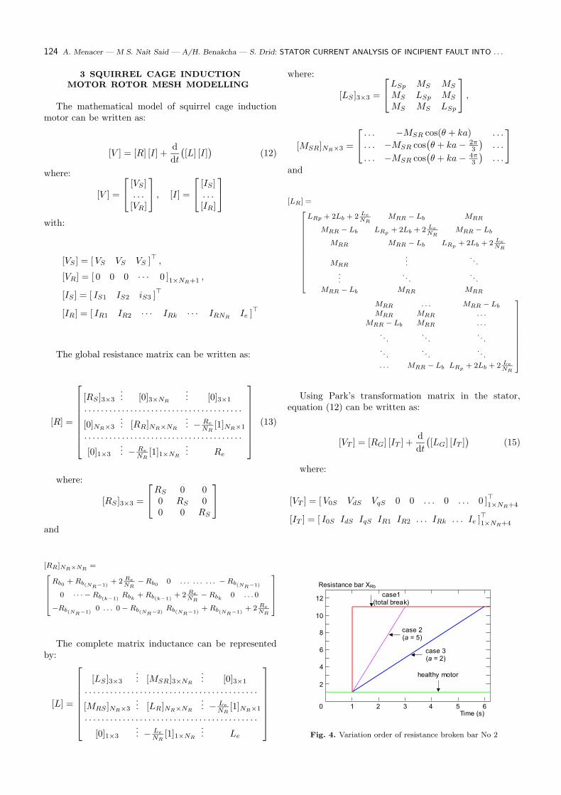
3 SQUIRREL CAGE INDUCTIONMOTOR ROTOR MESH MODELLING
The mathematical model of squirrel cage inductionmotor can be written as:
[V ] = [R] [I] +d
dt
(
[L] [I])
(12)
where:
[V ] =
[VS ]. . .
[VR]
, [I] =
[IS ]. . .
[IR]
with:
[VS ] = [ VS VS VS ]>
,
[VR] = [ 0 0 0 · · · 0 ]1×NR+1
,
[IS ] = [ IS1 IS2 iS3 ]>
[IR] = [ IR1 IR2 · · · IRk · · · IRNRIe ]
>
The global resistance matrix can be written as:
[R] =
[RS ]3×3
... [0]3×NR
... [0]3×1
. . . . . . . . . . . . . . . . . . . . . . . . . . . . . . . . . . . . . .
[0]NR×3
... [RR]NR×NR
... −Re
NR[1]NR×1
. . . . . . . . . . . . . . . . . . . . . . . . . . . . . . . . . . . . . .
[0]1×3
... −Re
NR[1]1×NR
... Re
(13)
where:
[RS ]3×3 =
RS 0 00 RS 00 0 RS
and
[RR]NR×NR=
Rb0 + Rb(NR−1)+ 2 Re
NR− Rb0 0 . . . . . . . . . − Rb(NR−1)
0 · · · − Rb(k−1)Rbk
+ Rb(k−1)+ 2 Re
NR− Rbk
0 . . . 0
−Rb(NR−1)0 . . . 0 − Rb(NR−2)
Rb(NR−1)+ Rb(NR−1)
+ 2 Re
NR
The complete matrix inductance can be representedby:
[L] =
[LS ]3×3
... [MSR]3×NR
... [0]3×1
. . . . . . . . . . . . . . . . . . . . . . . . . . . . . . . . . . . . . . . . .
[MRS ]NR×3
... [LR]NR×NR
... −Le
NR[1]NR×1
. . . . . . . . . . . . . . . . . . . . . . . . . . . . . . . . . . . . . . . . .
[0]1×3
... −Le
NR[1]1×NR
... Le
where:
[LS ]3×3 =
LSp MS MS
MS LSp MS
MS MS LSp
,
[MSR]NR×3 =
. . . −MSR cos(θ + ka) . . .
. . . −MSR cos(
θ + ka −2π3
)
. . .
. . . −MSR cos(
θ + ka −4π3
)
. . .
and
[LR] =
LRp + 2Lb + 2 Le
NRMRR − Lb MRR
MRR − Lb LRp+ 2Lb + 2 Le
NRMRR − Lb
MRR MRR − Lb LRp+ 2Lb + 2 Le
NR
MRR
..
.. . .
.
... . .
. . .
MRR − Lb MRR MRR
MRR . . . MRR − Lb
MRR MRR . . .
MRR − Lb MRR . . .
. . .. . .
. . .
. . .. . .
. . .
. . . MRR − Lb LRp+ 2Lb + 2 Le
NR
Using Park’s transformation matrix in the stator,equation (12) can be written as:
[VT ] = [RG] [IT ] +d
dt
(
[LG] [IT ])
(15)
where:
[VT ] = [ V0S VdS VqS 0 0 . . . 0 . . . 0 ]>
1×NR+4
[IT ] = [ I0S IdS IqS IR1 IR2 . . . IRk . . . Ie ]>
1×NR+4
case1(total break)
case 2(a = 5)
case 3(a = 2)
healthy motor
Resistance bar XRb
12
10
8
6
4
2
Time (s)0 1 2 3 4 5 6
Fig. 4. Variation order of resistance broken bar No 2

Journal of ELECTRICAL ENGINEERING VOL. 55, NO. 5-6, 2004 125
[RG] =
RS 0 0...
0 RS 0...
0 0 RS
.
.
.
. . . . . . . . ....
0 0 T1
.
.
.
0 −T1 sin(a) T1 cos(a)...
.
.....
.
.....
.
.
....
.
.
....
0 −T1 sin(NR − 1)a T1 cos(NR − 1)a...
.
.. . . . . . .
0 0 0...
0 0 . . .
0 −T1 sin(a) . . .
T1 T1 cos(a) . . .
. . . . . .Rb0 + Rb(NR−1)
+ 2 Re
NR−Rb0 0
. . .. . .
. . .
0 −Rb(k−1)Rbk
+ Rb(k−1)+ 2 Re
NR
. . .. . .
. . .
−Rb(NR−1)0 · · ·
. . . . . . . . .− Re
NR. . . . . .
. . . 0... 0
. . . −T1 sin(NR − 1)a... 0
. . . T1 cos(NR − 1)a... 0
. . . . . .... . . .
. . . −Rb(NR−1)
.
.
. − Re
NR
. . .. . .
.
.
....
−Rbk0
..
....
−Rb(NR−2)Rb(NR−1) + Rb(NR−2)
+ 2 Re
NR
.
.. − Re
NR
. . . . . .... . . .
. . . − Re
NR
.
.
. Re
[LG] =
LS + 2MS 0 0... 0
0 LS − MS 0... LPR
0 0 LS − MS
.
.
. 0
. . . . . . . . .... . . .
0 LPR 0... LP
0 LPR cos(a) LPR sin(a)...
. . .
..
....
..
.... MRR
.
.
....
.
.
....
. . .
0 LPR cos(NR − 1)a LPR sin(NR − 1)a... MRR − Lb
. . . . . . . . . . . . . . .
0 0 0... −Le/NR
0 . . . . . . 0... 0
LPR cos(a) . . . . . . LPR cos(NR − 1)a... 0
LPR sin(a) . . . . . . LPR sin(NR − 1)a... 0
. . . . . . . . . . . .... . . .
MRR − Lb MRR . . . MRR − Lb
..
. −Le/NR
. . .. . .
. . .. . .
.
.
....
MRR − Lb LP MRR − Lb MRR
.
.....
. . .. . .
. . .. . .
..
....
MRR . . . MRR − Lb LP
.
.
. −Le/NR
. . . . . . . . . . . .... . . .
. . . . . . . . . −Le/NR
.
.
. Le
with: T1 =√
3
2ωRMSR , LP = LRp
+ 2Lb + 2 Le
NR,
LPR =√
3
2LSR . The mechanical equation is:
d
dtωm =
1
Jm
(
Ce − Cr
)
(16)
where: ωm = dθm
dtand
Ce =√
3
2pMSR
{
IqS
NR−1∑
k=0
Ik+1 cos(ka)
−IdS
NR−1∑
k=0
Ik+1 sin(ka)}
.
4 INCIPIENT ROTOR FAULTS SIMULATION
For a three phase squirrel cage motor with NR-bars,
plus one end ring current, equations (15) and (16) can be
resolved using the fourth Runge-Kutta method.
Using a computer program written in Matlab, the par-
tial or the total breakage fault in the bar is modelled by
the assumed linear change of the value of the resistanceRbF named fault bar resistance. The variation of the re-sistance RbF as a function of time is modelled by relation(17) represented for three cases of the resistance time ra-tio named α .
RbFk = Rb
(
1 + α(t − t0))
(17)
where: α = tg(γ) ; angle resistance rate as shown in Fig. 4.
126 A. Menacer — M S. Naıt Said — A/H. Benakcha — S. Drid: STATOR CURRENT ANALYSIS OF INCIPIENT FAULT INTO . . .
wr (rpm)
Time (s)0 1 2 3 4 5 6
2500
1500
1000
500
3000
2000
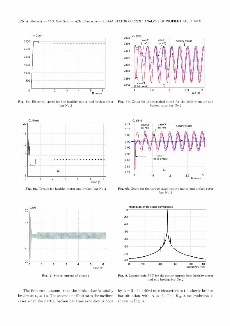
Fig. 5a. Electrical speed for the healthy motor and broken rotor
bar No 2
wr (rpm)
2876
2872
2870
2878
2874
2868
2866
2864
Time (s)1 1.5 32 2.5
case 2(a =5)
case 3(a =2)
case 1(total break)
healthy motor
b)
Fig. 5b. Zoom for the electrical speed for the healthy motor and
broken rotor bar No 2
Time (s)0 1 2 3 4 5 6
Ce (Nm)20
15
10
5
0
-5
a)
Fig. 6a. Torque for healthy motor and broken bar No 2
case 2(a =5)
case 3(a =5)
Ce (Nm)
Time (s)1 1.5 32 2.5
case 1(total break)
healthy motor
b)
3.15
2.85
3.10
3.05
3.00
2.95
2.90
2.80
2.75
Fig. 6b. Zoom for the torque cases healthy motor and broken rotor
bar No 2
20
Time (s)
0 1 2 3 4 5 6
is l (A)
10
0
-10
-20
Fig. 7. Stator current of phase 1
Magnitude of the stator current (dB)
-60
-70
-40
-50
-20
-30
0
-10
Frequency (Hz)0 20 40 60 80 100
Fig. 8. Logarithmic FFT for the stator current from healthy motor
and one broken bar No 2
The first case assumes that the broken bar is totally
broken at t0 = 1 s. The second one illustrates the medium
cases when the partial broken bar time evolution is done
by α = 5. The third case characterizes the slowly broken
bar situation with α = 2. The RbF -time evolution is
shown in Fig. 4.
Journal of ELECTRICAL ENGINEERING VOL. 55, NO. 5-6, 2004 127
Time (s)
0 1 2 3 4 5 6
irb2 (2)
a)
1500
0
1000
500
-500
-1000
-1500
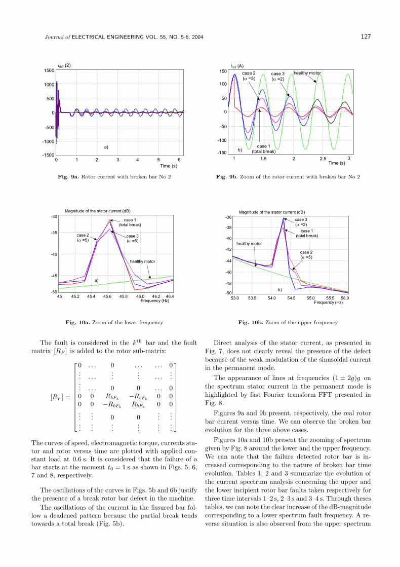
Fig. 9a. Rotor current with broken bar No 2
case 2(a =5)
case 3(a =2)
irb2 (A)
Time (s)1 1.5 32 2.5
case 1(total break)
healthy motor
b)
150
100
50
0
-50
-100
-150
Fig. 9b. Zoom of the rotor current with broken bar No 2
case 2(a =5)
case 3(a =5)
healthy motor
Magnitude of the stator current (dB)
a)
Frequency (Hz)45 45.2 45.4 45.6 45.8 46.0 46.2 46.4
-35
-45
-40
-30
-50
case 1(total break)
Fig. 10a. Zoom of the lower frequency
Magnitude of the stator current (dB)
b)
-36
-38
-40
-42
-44
-46
-48
-50
55.5 56.054.053.0Frequency (Hz)
53.5 54.5 55.0
healthy motor
case 3(a =2)
case 1(total break)
case 2(a =5)
Fig. 10b. Zoom of the upper frequency
The fault is considered in the kth bar and the faultmatrix [RF ] is added to the rotor sub-matrix:
[RF ] =
0 . . . 0 . . . . . . 0... . . .
...... . . .
...... . . . 0 0 . . . 00 0 RbFk
−RbFk0 0
0 0 −RbFkRbFk
0 0...
... 0 0...
......
......
......
...
The curves of speed, electromagnetic torque, currents sta-tor and rotor versus time are plotted with applied con-stant load at 0.6 s. It is considered that the failure of abar starts at the moment t0 = 1 s as shown in Figs. 5, 6,7 and 8, respectively.
The oscillations of the curves in Figs. 5b and 6b justifythe presence of a break rotor bar defect in the machine.
The oscillations of the current in the fissured bar fol-low a deadened pattern because the partial break tendstowards a total break (Fig. 5b).
Direct analysis of the stator current, as presented inFig. 7, does not clearly reveal the presence of the defectbecause of the weak modulation of the sinusoidal currentin the permanent mode.
The appearance of lines at frequencies (1 ± 2g)g onthe spectrum stator current in the permanent mode ishighlighted by fast Fourier transform FFT presented inFig. 8.
Figures 9a and 9b present, respectively, the real rotorbar current versus time. We can observe the broken barevolution for the three above cases.
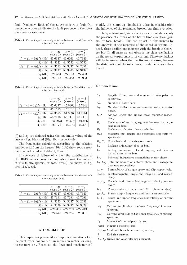
Figures 10a and 10b present the zooming of spectrumgiven by Fig. 8 around the lower and the upper frequency.We can note that the failure detected rotor bar is in-creased corresponding to the nature of broken bar timeevolution. Tables 1, 2 and 3 summarize the evolution ofthe current spectrum analysis concerning the upper andthe lower incipient rotor bar faults taken respectively forthree time intervals 1–2 s, 2–3 s and 3–4 s. Through thesestables, we can note the clear increase of the dB-magnitudecorresponding to a lower spectrum fault frequency. A re-verse situation is also observed from the upper spectrum
128 A. Menacer — M S. Naıt Said — A/H. Benakcha — S. Drid: STATOR CURRENT ANALYSIS OF INCIPIENT FAULT INTO . . .
fault frequency. Both of the above spectrum fault fre-quency evolutions indicate the fault presence in the rotorbar since its existence.
Table 1. Current spectrum analysis taken between 1 and 2 seconds
after incipient fault
α → ∞ α = 5 α = 2(case 1) (case 2) (case 3)
f1 = (1 − 2g)fs (Hz) 45.6347 45.6963 45.7349f ′1 (Hz) 44.5622 44.5552 44.5552
f2 = (1 + 2g)fs (Hz) 54.3653 54.3037 54.2651f ′2 (Hz) 54.3137 54.3265 54.3137
A1 (dB) −26.594 −27.193 −27.493A2 (dB) −23.153 −23.483 −23.903
Table 2. Current spectrum analysis taken between 2 and 3 seconds
after incipient fault
α → ∞ α = 5 α = 2(case 1) (case 2) (case 3)
f1 = (1 − 2g)fs (Hz) 45.6347 45.6963 45.7349f ′1 (Hz) 45.1613 45.1613 45.1613
f2 = (1 + 2g)fs (Hz) 54.3653 54.3037 54.2651f ′2 (Hz) 53.7113 53.7113 53.7113
A1 (dB) −23.5973 −23.597 −24.266A2 (dB) −23.175 −22.784 −22.661
f ′1 and f ′
2 are deduced using the maximum values of thecurves (Fig. 10a) and (Fig. 10b) respectively.
The frequencies calculated according to the relationand deduced from the figures (10a, 10b) show good agree-ment as indicated in Tables 1, 2 and 3.
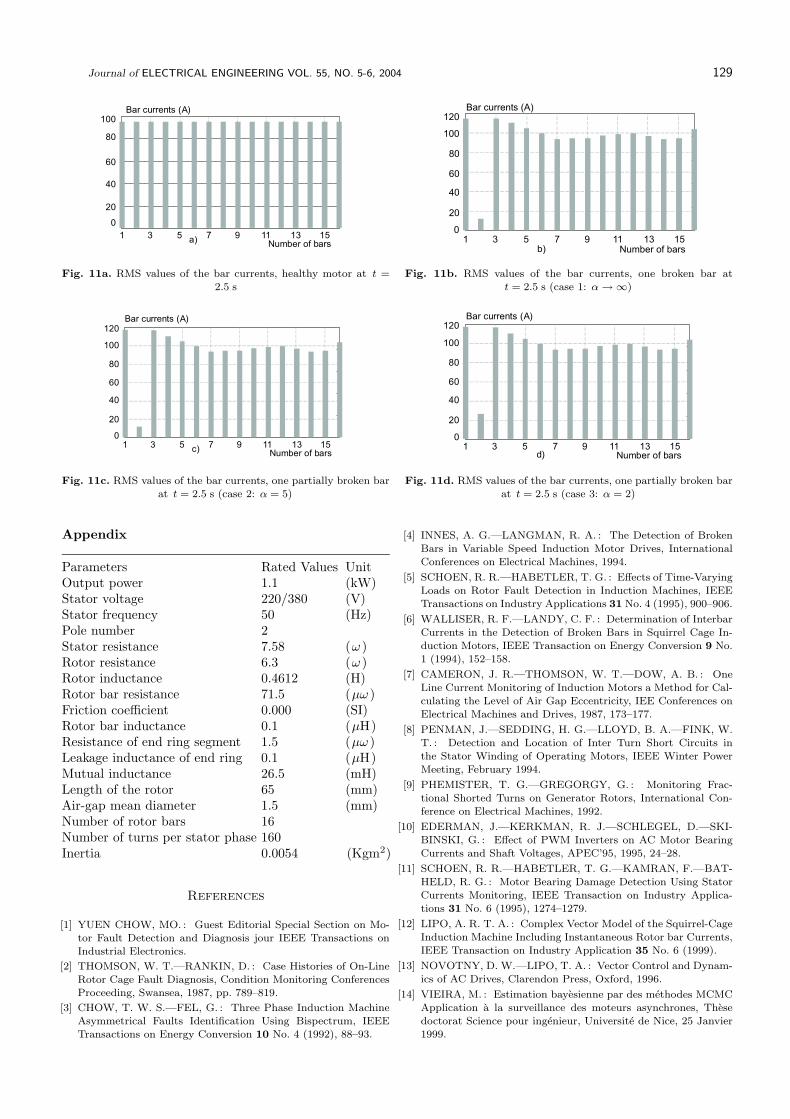
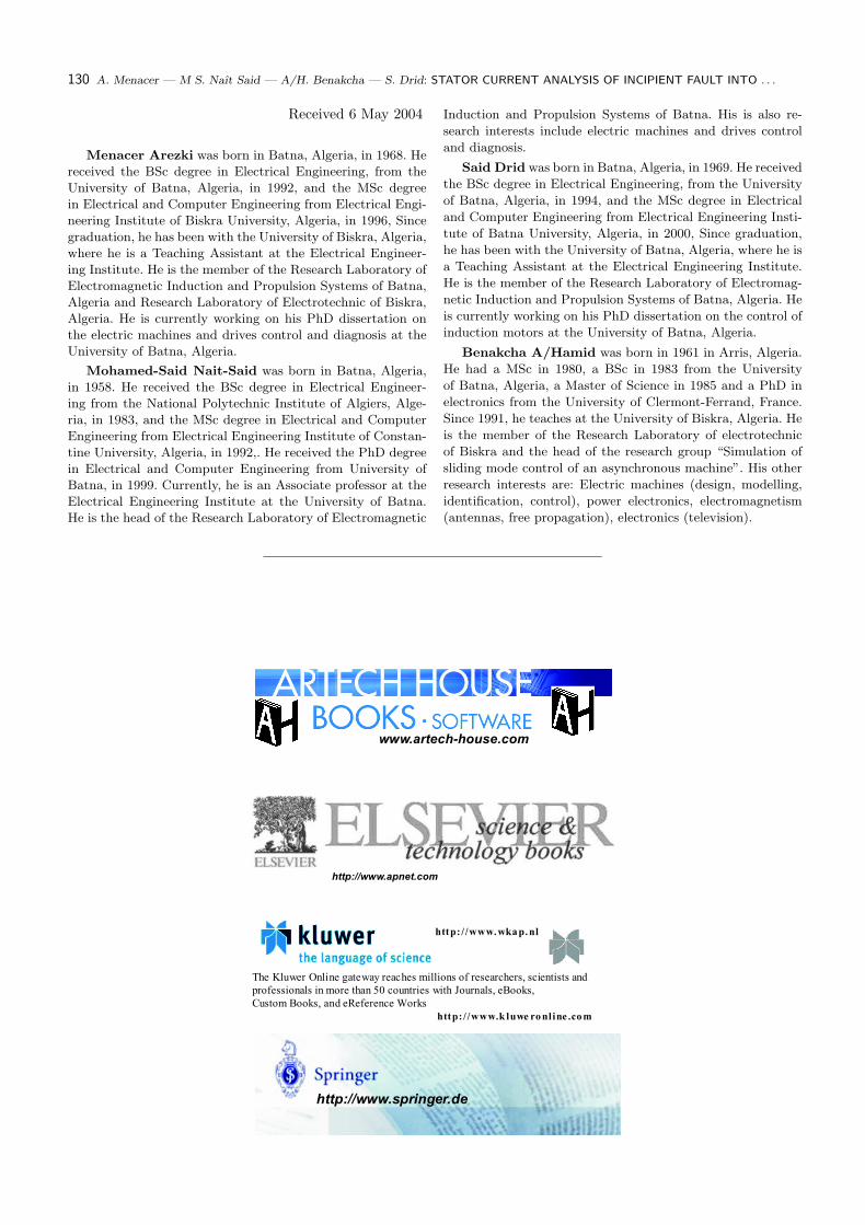
In the case of failure of a bar, the distribution ofthe RMS values currents bars also shows the natureof this failure (partial or total break), as shown in fig-ures 11a, b, c, d.
Table 3. Current spectrum analysis taken between 3 and 4 seconds
after incipient fault
α → ∞ α = 5 α = 2(case 1) (case 2) (case 3)
f1 = (1 − 2g)fs (Hz) 45.6347 45.6963 45.7349f ′1 (Hz) 45.7691 45.7691 45.7691
f2 = (1 + 2g)fs (Hz) 54.3653 54.3037 54.2651f ′2 (Hz) 54.9329 54.9297 54.9329
A1 (dB) −23.488 −22.709 −22.413A2 (dB) −24.549 −24.765 −25.391
5 CONCLUSION
This paper has presented a computer simulation of anincipient rotor bar fault of an induction motor for diag-nostic purposes. Based on the developed mathematical
model, the computer simulation takes in considerationthe influence of the resistance broken bar time evolution.
The spectrum analysis of the stator current shows onlythe presence of a break of the bar in time evolution (par-tial or total break). This can be set in obviousness bythe analysis of the response of the speed or torque. In-deed, these oscillations increase with the break of the ro-tor bar. In all cases we can observe incipient oscillationson the speed, torque end stator current. These oscillationswill be increased when the bar fissure increases, becausethe distribution of the rotor bar currents becomes unbal-anced.
Nomenclature
l, p Length of the rotor and number of poles pairs re-spectively.
NR Number of rotor bars.
NS Number of effective series connected coils per statorphase.
δ, D Air-gap length and air-gap mean diameter respec-tively.
Re Resistance of end ring segment between two adja-cent rotor bars.
RS Resistance of stator phase a winding.
B, α Magnetic flux density and resistance time ratio re-spectively.
Rb, Re Rotor bar and rotor ring resistance.
Lb Leakage inductance of rotor bar.
Le Leakage inductance of end ring segment betweentwo adjacent rotor bars.
LSp Principal inductance magnetizing stator phase.
LS , LSf Total inductance of a stator phase and Leakage in-ductance respectively.
µ0, g Permeability of air gap space and slip respectively.
Ce, Cr Electromagnetic torque and torque of load respec-tively.
ωr, ωm Electric and mechanical angular velocity respec-tively.
ISn Phases stator currents; n = 1, 2, 3 (phase number).
fS , Jm Stator supply frequency and inertia respectively.
f1, f2 Lower and upper frequency respectively of currentspectrum.
A1 Current amplitude at the lower frequency of currentspectrum.
A2 Current amplitude at the upper frequency of currentspectrum.
t0 Moment of the incipient failure.
mmf Magneto-motoric force.
iRk, ibk Mesh and branch current respectively.
Ie End ring current.
Ids, Iqs Direct and quadratic park current.
Journal of ELECTRICAL ENGINEERING VOL. 55, NO. 5-6, 2004 129
Bar currents (A)
Number of bars1 53 15137 9 11
100
0
20
40
60
80
a)
Fig. 11a. RMS values of the bar currents, healthy motor at t =
2.5 s
Bar currents (A)
Number of bars1 53 7 9 11
b)
100
0
20
40
60
80
120
1513
Fig. 11b. RMS values of the bar currents, one broken bar at
t = 2.5 s (case 1: α → ∞)
Number of bars1 53 15137 9 11
c)
100
0
20
40
60
80
120Bar currents (A)
Fig. 11c. RMS values of the bar currents, one partially broken barat t = 2.5 s (case 2: α = 5)
Number of bars1 53 15137 9 11
d)
100
0
20
40
60
80
120Bar currents (A)
Fig. 11d. RMS values of the bar currents, one partially broken barat t = 2.5 s (case 3: α = 2)
Appendix
Parameters Rated Values UnitOutput power 1.1 (kW)Stator voltage 220/380 (V)Stator frequency 50 (Hz)Pole number 2Stator resistance 7.58 (ω )Rotor resistance 6.3 (ω )Rotor inductance 0.4612 (H)Rotor bar resistance 71.5 (µω )Friction coefficient 0.000 (SI)Rotor bar inductance 0.1 (µH)Resistance of end ring segment 1.5 (µω )Leakage inductance of end ring 0.1 (µH)Mutual inductance 26.5 (mH)Length of the rotor 65 (mm)Air-gap mean diameter 1.5 (mm)Number of rotor bars 16Number of turns per stator phase 160Inertia 0.0054 (Kgm2)
References
[1] YUEN CHOW, MO. : Guest Editorial Special Section on Mo-
tor Fault Detection and Diagnosis jour IEEE Transactions on
Industrial Electronics.
[2] THOMSON, W. T.—RANKIN, D. : Case Histories of On-Line
Rotor Cage Fault Diagnosis, Condition Monitoring Conferences
Proceeding, Swansea, 1987, pp. 789–819.
[3] CHOW, T. W. S.—FEL, G. : Three Phase Induction Machine
Asymmetrical Faults Identification Using Bispectrum, IEEETransactions on Energy Conversion 10 No. 4 (1992), 88–93.
[4] INNES, A. G.—LANGMAN, R. A. : The Detection of Broken
Bars in Variable Speed Induction Motor Drives, International
Conferences on Electrical Machines, 1994.
[5] SCHOEN, R. R.—HABETLER, T. G. : Effects of Time-Varying
Loads on Rotor Fault Detection in Induction Machines, IEEE
Transactions on Industry Applications 31 No. 4 (1995), 900–906.
[6] WALLISER, R. F.—LANDY, C. F. : Determination of Interbar
Currents in the Detection of Broken Bars in Squirrel Cage In-
duction Motors, IEEE Transaction on Energy Conversion 9 No.
1 (1994), 152–158.
[7] CAMERON, J. R.—THOMSON, W. T.—DOW, A. B. : One
Line Current Monitoring of Induction Motors a Method for Cal-
culating the Level of Air Gap Eccentricity, IEE Conferences on
Electrical Machines and Drives, 1987, 173–177.
[8] PENMAN, J.—SEDDING, H. G.—LLOYD, B. A.—FINK, W.
T. : Detection and Location of Inter Turn Short Circuits in
the Stator Winding of Operating Motors, IEEE Winter Power
Meeting, February 1994.
[9] PHEMISTER, T. G.—GREGORGY, G. : Monitoring Frac-
tional Shorted Turns on Generator Rotors, International Con-
ference on Electrical Machines, 1992.
[10] EDERMAN, J.—KERKMAN, R. J.—SCHLEGEL, D.—SKI-
BINSKI, G. : Effect of PWM Inverters on AC Motor Bearing
Currents and Shaft Voltages, APEC’95, 1995, 24–28.
[11] SCHOEN, R. R.—HABETLER, T. G.—KAMRAN, F.—BAT-
HELD, R. G. : Motor Bearing Damage Detection Using Stator
Currents Monitoring, IEEE Transaction on Industry Applica-
tions 31 No. 6 (1995), 1274–1279.
[12] LIPO, A. R. T. A. : Complex Vector Model of the Squirrel-Cage
Induction Machine Including Instantaneous Rotor bar Currents,
IEEE Transaction on Industry Application 35 No. 6 (1999).
[13] NOVOTNY, D. W.—LIPO, T. A. : Vector Control and Dynam-
ics of AC Drives, Clarendon Press, Oxford, 1996.
[14] VIEIRA, M. : Estimation bayesienne par des methodes MCMC
Application a la surveillance des moteurs asynchrones, These
doctorat Science pour ingenieur, Universite de Nice, 25 Janvier
1999.
130 A. Menacer — M S. Naıt Said — A/H. Benakcha — S. Drid: STATOR CURRENT ANALYSIS OF INCIPIENT FAULT INTO . . .
Received 6 May 2004
Menacer Arezki was born in Batna, Algeria, in 1968. He
received the BSc degree in Electrical Engineering, from the
University of Batna, Algeria, in 1992, and the MSc degree
in Electrical and Computer Engineering from Electrical Engi-
neering Institute of Biskra University, Algeria, in 1996, Since
graduation, he has been with the University of Biskra, Algeria,
where he is a Teaching Assistant at the Electrical Engineer-
ing Institute. He is the member of the Research Laboratory of
Electromagnetic Induction and Propulsion Systems of Batna,
Algeria and Research Laboratory of Electrotechnic of Biskra,
Algeria. He is currently working on his PhD dissertation on
the electric machines and drives control and diagnosis at the
University of Batna, Algeria.
Mohamed-Said Nait-Said was born in Batna, Algeria,
in 1958. He received the BSc degree in Electrical Engineer-
ing from the National Polytechnic Institute of Algiers, Alge-
ria, in 1983, and the MSc degree in Electrical and Computer
Engineering from Electrical Engineering Institute of Constan-
tine University, Algeria, in 1992,. He received the PhD degree
in Electrical and Computer Engineering from University of
Batna, in 1999. Currently, he is an Associate professor at the
Electrical Engineering Institute at the University of Batna.
He is the head of the Research Laboratory of Electromagnetic
Induction and Propulsion Systems of Batna. His is also re-
search interests include electric machines and drives control
and diagnosis.
Said Drid was born in Batna, Algeria, in 1969. He received
the BSc degree in Electrical Engineering, from the University
of Batna, Algeria, in 1994, and the MSc degree in Electrical
and Computer Engineering from Electrical Engineering Insti-
tute of Batna University, Algeria, in 2000, Since graduation,
he has been with the University of Batna, Algeria, where he is
a Teaching Assistant at the Electrical Engineering Institute.
He is the member of the Research Laboratory of Electromag-
netic Induction and Propulsion Systems of Batna, Algeria. He
is currently working on his PhD dissertation on the control of
induction motors at the University of Batna, Algeria.
Benakcha A/Hamid was born in 1961 in Arris, Algeria.
He had a MSc in 1980, a BSc in 1983 from the University
of Batna, Algeria, a Master of Science in 1985 and a PhD in
electronics from the University of Clermont-Ferrand, France.
Since 1991, he teaches at the University of Biskra, Algeria. He
is the member of the Research Laboratory of electrotechnic
of Biskra and the head of the research group “Simulation of
sliding mode control of an asynchronous machine”. His other
research interests are: Electric machines (design, modelling,
identification, control), power electronics, electromagnetism
(antennas, free propagation), electronics (television).
www.artech-house.com
http://www.apnet.com
The Kluwer Online gateway reaches millions of researchers, scientists and
professionals in more than 50 countries with Journals, eBooks,
Custom Books, and eReference Works
http: / /www.k luwe ronl ine .com
http: / /www.wkap.nl
http://www.springer.de