Embed Size (px)
Citation preview
© Copyright 2009 DEHN+SÖHNE GmbH + Co KG protected by ISO 16016 Seite 1 von 6 11.03.10
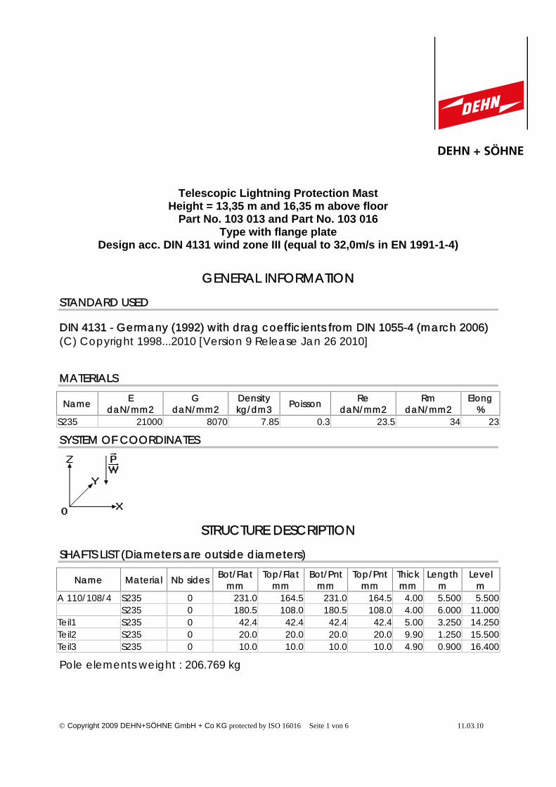
Telescopic Lightning Protection MastHeight = 13,35 m and 16,35 m above floor
Part No. 103 013 and Part No. 103 016Type with flange plate
Design acc. DIN 4131 wind zone III (equal to 32,0m/s in EN 1991-1-4)
GENERAL INFORMATION
STANDARD USED
DIN 4131 - Germany (1992) with drag coefficients from DIN 1055-4 (march 2006)(C) Copyright 1998...2010 [Version 9 Release Jan 26 2010]
MATERIALS
Name EdaN/mm2
GdaN/mm2
Densitykg/dm3 Poisson Re
daN/mm2Rm
daN/mm2Elong
%S235 21000 8070 7.85 0.3 23.5 34 23
SYSTEM OF COORDINATES
STRUCTURE DESCRIPTION
SHAFTS LIST (Diameters are outside diameters)
Name Material Nb sides Bot/Flatmm
Top/Flatmm
Bot/Pntmm
Top/Pntmm
Thickmm
Lengthm
Levelm
A 110/108/4 S235 0 231.0 164.5 231.0 164.5 4.00 5.500 5.500S235 0 180.5 108.0 180.5 108.0 4.00 6.000 11.000
Teil1 S235 0 42.4 42.4 42.4 42.4 5.00 3.250 14.250Teil2 S235 0 20.0 20.0 20.0 20.0 9.90 1.250 15.500Teil3 S235 0 10.0 10.0 10.0 10.0 4.90 0.900 16.400
Pole elements weight : 206.769 kg
© Copyright 2009 DEHN+SÖHNE GmbH + Co KG protected by ISO 16016 Seite 2 von 6 11.03.10
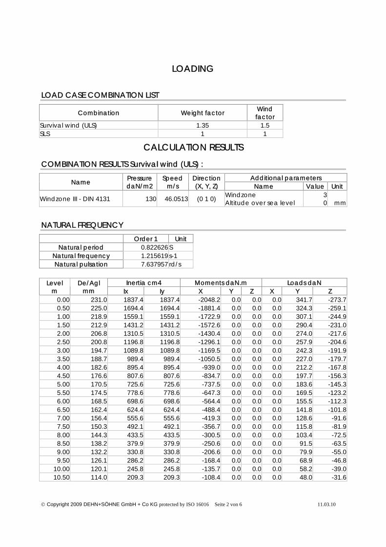
LOADING
LOAD CASE COMBINATION LIST
Combination Weight factor Windfactor
Survival wind (ULS) 1.35 1.5SLS 1 1
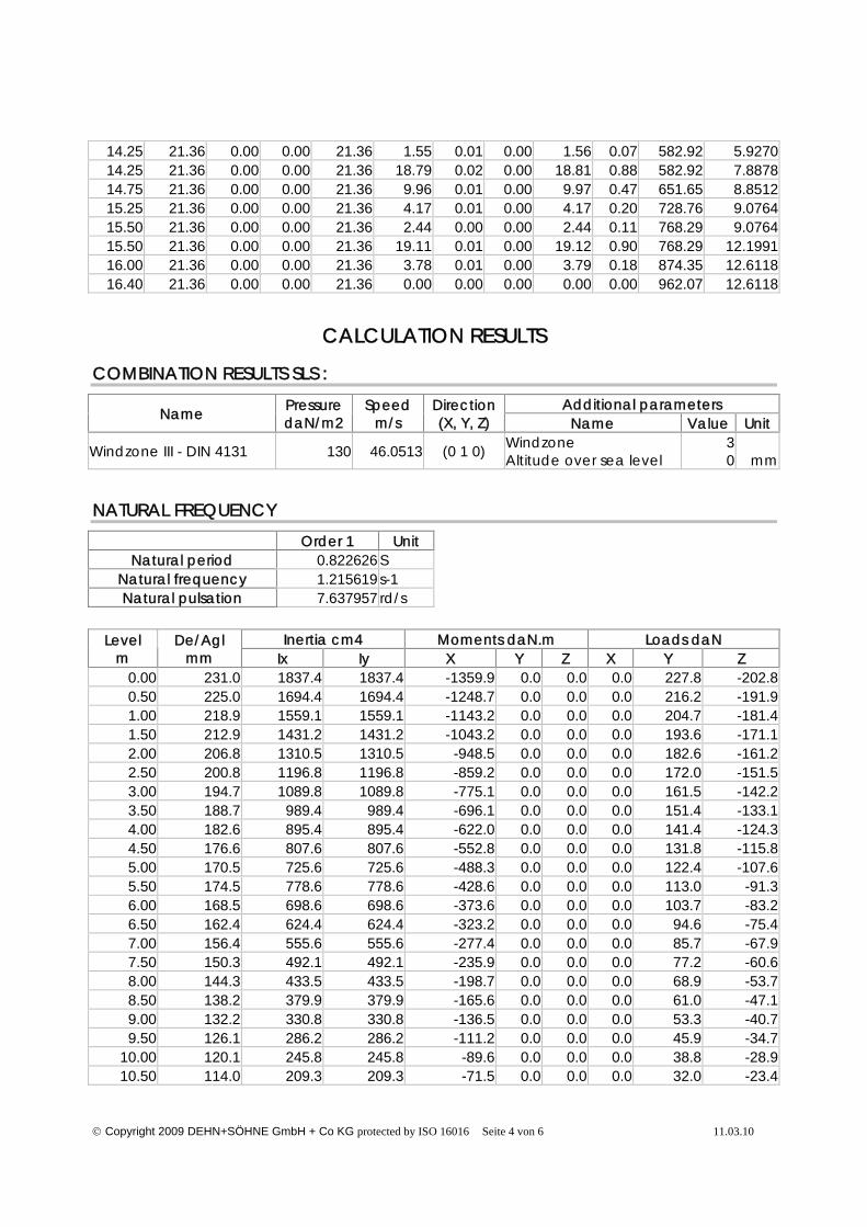
CALCULATION RESULTS
COMBINATION RESULTS Survival wind (ULS) :
Additional parametersName PressuredaN/m2
Speedm/s
Direction(X, Y, Z) Name Value Unit
Windzone III - DIN 4131 130 46.0513 (0 1 0) WindzoneAltitude over sea level
30
mm
NATURAL FREQUENCY
Order 1 UnitNatural period 0.822626 S
Natural frequency 1.215619 s-1Natural pulsation 7.637957 rd/s
Inertia cm4 Moments daN.m Loads daNLevelm
De/Aglmm Ix Iy X Y Z X Y Z
0.00 231.0 1837.4 1837.4 -2048.2 0.0 0.0 0.0 341.7 -273.70.50 225.0 1694.4 1694.4 -1881.4 0.0 0.0 0.0 324.3 -259.11.00 218.9 1559.1 1559.1 -1722.9 0.0 0.0 0.0 307.1 -244.91.50 212.9 1431.2 1431.2 -1572.6 0.0 0.0 0.0 290.4 -231.02.00 206.8 1310.5 1310.5 -1430.4 0.0 0.0 0.0 274.0 -217.62.50 200.8 1196.8 1196.8 -1296.1 0.0 0.0 0.0 257.9 -204.63.00 194.7 1089.8 1089.8 -1169.5 0.0 0.0 0.0 242.3 -191.93.50 188.7 989.4 989.4 -1050.5 0.0 0.0 0.0 227.0 -179.74.00 182.6 895.4 895.4 -939.0 0.0 0.0 0.0 212.2 -167.84.50 176.6 807.6 807.6 -834.7 0.0 0.0 0.0 197.7 -156.35.00 170.5 725.6 725.6 -737.5 0.0 0.0 0.0 183.6 -145.35.50 174.5 778.6 778.6 -647.3 0.0 0.0 0.0 169.5 -123.26.00 168.5 698.6 698.6 -564.4 0.0 0.0 0.0 155.5 -112.36.50 162.4 624.4 624.4 -488.4 0.0 0.0 0.0 141.8 -101.87.00 156.4 555.6 555.6 -419.3 0.0 0.0 0.0 128.6 -91.67.50 150.3 492.1 492.1 -356.7 0.0 0.0 0.0 115.8 -81.98.00 144.3 433.5 433.5 -300.5 0.0 0.0 0.0 103.4 -72.58.50 138.2 379.9 379.9 -250.6 0.0 0.0 0.0 91.5 -63.59.00 132.2 330.8 330.8 -206.6 0.0 0.0 0.0 79.9 -55.09.50 126.1 286.2 286.2 -168.4 0.0 0.0 0.0 68.9 -46.8
10.00 120.1 245.8 245.8 -135.7 0.0 0.0 0.0 58.2 -39.010.50 114.0 209.3 209.3 -108.4 0.0 0.0 0.0 48.0 -31.6
© Copyright 2009 DEHN+SÖHNE GmbH + Co KG protected by ISO 16016 Seite 3 von 6 11.03.10
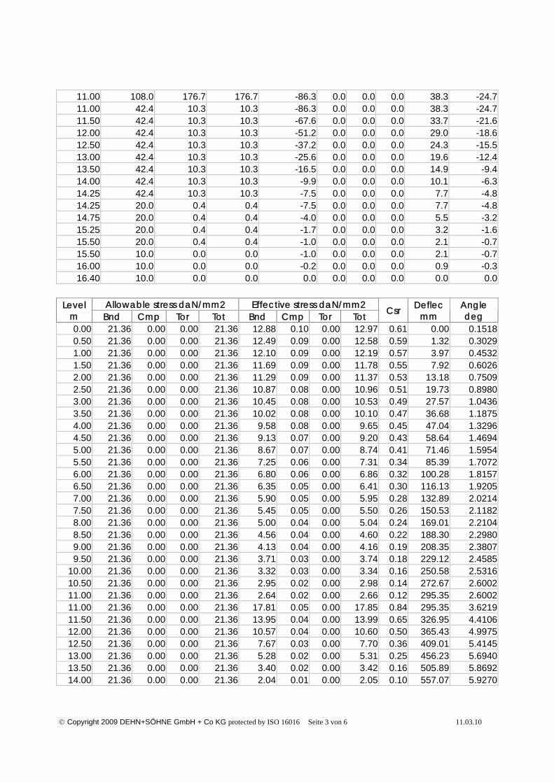
11.00 108.0 176.7 176.7 -86.3 0.0 0.0 0.0 38.3 -24.711.00 42.4 10.3 10.3 -86.3 0.0 0.0 0.0 38.3 -24.711.50 42.4 10.3 10.3 -67.6 0.0 0.0 0.0 33.7 -21.612.00 42.4 10.3 10.3 -51.2 0.0 0.0 0.0 29.0 -18.612.50 42.4 10.3 10.3 -37.2 0.0 0.0 0.0 24.3 -15.513.00 42.4 10.3 10.3 -25.6 0.0 0.0 0.0 19.6 -12.413.50 42.4 10.3 10.3 -16.5 0.0 0.0 0.0 14.9 -9.414.00 42.4 10.3 10.3 -9.9 0.0 0.0 0.0 10.1 -6.314.25 42.4 10.3 10.3 -7.5 0.0 0.0 0.0 7.7 -4.814.25 20.0 0.4 0.4 -7.5 0.0 0.0 0.0 7.7 -4.814.75 20.0 0.4 0.4 -4.0 0.0 0.0 0.0 5.5 -3.215.25 20.0 0.4 0.4 -1.7 0.0 0.0 0.0 3.2 -1.615.50 20.0 0.4 0.4 -1.0 0.0 0.0 0.0 2.1 -0.715.50 10.0 0.0 0.0 -1.0 0.0 0.0 0.0 2.1 -0.716.00 10.0 0.0 0.0 -0.2 0.0 0.0 0.0 0.9 -0.316.40 10.0 0.0 0.0 0.0 0.0 0.0 0.0 0.0 0.0
Allowable stress daN/mm2 Effective stress daN/mm2Levelm Bnd Cmp Tor Tot Bnd Cmp Tor Tot Csr Deflec
mmAngledeg
0.00 21.36 0.00 0.00 21.36 12.88 0.10 0.00 12.97 0.61 0.00 0.15180.50 21.36 0.00 0.00 21.36 12.49 0.09 0.00 12.58 0.59 1.32 0.30291.00 21.36 0.00 0.00 21.36 12.10 0.09 0.00 12.19 0.57 3.97 0.45321.50 21.36 0.00 0.00 21.36 11.69 0.09 0.00 11.78 0.55 7.92 0.60262.00 21.36 0.00 0.00 21.36 11.29 0.09 0.00 11.37 0.53 13.18 0.75092.50 21.36 0.00 0.00 21.36 10.87 0.08 0.00 10.96 0.51 19.73 0.89803.00 21.36 0.00 0.00 21.36 10.45 0.08 0.00 10.53 0.49 27.57 1.04363.50 21.36 0.00 0.00 21.36 10.02 0.08 0.00 10.10 0.47 36.68 1.18754.00 21.36 0.00 0.00 21.36 9.58 0.08 0.00 9.65 0.45 47.04 1.32964.50 21.36 0.00 0.00 21.36 9.13 0.07 0.00 9.20 0.43 58.64 1.46945.00 21.36 0.00 0.00 21.36 8.67 0.07 0.00 8.74 0.41 71.46 1.59545.50 21.36 0.00 0.00 21.36 7.25 0.06 0.00 7.31 0.34 85.39 1.70726.00 21.36 0.00 0.00 21.36 6.80 0.06 0.00 6.86 0.32 100.28 1.81576.50 21.36 0.00 0.00 21.36 6.35 0.05 0.00 6.41 0.30 116.13 1.92057.00 21.36 0.00 0.00 21.36 5.90 0.05 0.00 5.95 0.28 132.89 2.02147.50 21.36 0.00 0.00 21.36 5.45 0.05 0.00 5.50 0.26 150.53 2.11828.00 21.36 0.00 0.00 21.36 5.00 0.04 0.00 5.04 0.24 169.01 2.21048.50 21.36 0.00 0.00 21.36 4.56 0.04 0.00 4.60 0.22 188.30 2.29809.00 21.36 0.00 0.00 21.36 4.13 0.04 0.00 4.16 0.19 208.35 2.38079.50 21.36 0.00 0.00 21.36 3.71 0.03 0.00 3.74 0.18 229.12 2.4585
10.00 21.36 0.00 0.00 21.36 3.32 0.03 0.00 3.34 0.16 250.58 2.531610.50 21.36 0.00 0.00 21.36 2.95 0.02 0.00 2.98 0.14 272.67 2.600211.00 21.36 0.00 0.00 21.36 2.64 0.02 0.00 2.66 0.12 295.35 2.600211.00 21.36 0.00 0.00 21.36 17.81 0.05 0.00 17.85 0.84 295.35 3.621911.50 21.36 0.00 0.00 21.36 13.95 0.04 0.00 13.99 0.65 326.95 4.410612.00 21.36 0.00 0.00 21.36 10.57 0.04 0.00 10.60 0.50 365.43 4.997512.50 21.36 0.00 0.00 21.36 7.67 0.03 0.00 7.70 0.36 409.01 5.414513.00 21.36 0.00 0.00 21.36 5.28 0.02 0.00 5.31 0.25 456.23 5.694013.50 21.36 0.00 0.00 21.36 3.40 0.02 0.00 3.42 0.16 505.89 5.869214.00 21.36 0.00 0.00 21.36 2.04 0.01 0.00 2.05 0.10 557.07 5.9270
© Copyright 2009 DEHN+SÖHNE GmbH + Co KG protected by ISO 16016 Seite 4 von 6 11.03.10
14.25 21.36 0.00 0.00 21.36 1.55 0.01 0.00 1.56 0.07 582.92 5.927014.25 21.36 0.00 0.00 21.36 18.79 0.02 0.00 18.81 0.88 582.92 7.887814.75 21.36 0.00 0.00 21.36 9.96 0.01 0.00 9.97 0.47 651.65 8.851215.25 21.36 0.00 0.00 21.36 4.17 0.01 0.00 4.17 0.20 728.76 9.076415.50 21.36 0.00 0.00 21.36 2.44 0.00 0.00 2.44 0.11 768.29 9.076415.50 21.36 0.00 0.00 21.36 19.11 0.01 0.00 19.12 0.90 768.29 12.199116.00 21.36 0.00 0.00 21.36 3.78 0.01 0.00 3.79 0.18 874.35 12.611816.40 21.36 0.00 0.00 21.36 0.00 0.00 0.00 0.00 0.00 962.07 12.6118
CALCULATION RESULTS
COMBINATION RESULTS SLS :
Additional parametersName PressuredaN/m2
Speedm/s
Direction(X, Y, Z) Name Value Unit
Windzone III - DIN 4131 130 46.0513 (0 1 0) WindzoneAltitude over sea level
30
mm
NATURAL FREQUENCY
Order 1 UnitNatural period 0.822626 S
Natural frequency 1.215619 s-1Natural pulsation 7.637957 rd/s
Inertia cm4 Moments daN.m Loads daNLevelm
De/Aglmm Ix Iy X Y Z X Y Z
0.00 231.0 1837.4 1837.4 -1359.9 0.0 0.0 0.0 227.8 -202.80.50 225.0 1694.4 1694.4 -1248.7 0.0 0.0 0.0 216.2 -191.91.00 218.9 1559.1 1559.1 -1143.2 0.0 0.0 0.0 204.7 -181.41.50 212.9 1431.2 1431.2 -1043.2 0.0 0.0 0.0 193.6 -171.12.00 206.8 1310.5 1310.5 -948.5 0.0 0.0 0.0 182.6 -161.22.50 200.8 1196.8 1196.8 -859.2 0.0 0.0 0.0 172.0 -151.53.00 194.7 1089.8 1089.8 -775.1 0.0 0.0 0.0 161.5 -142.23.50 188.7 989.4 989.4 -696.1 0.0 0.0 0.0 151.4 -133.14.00 182.6 895.4 895.4 -622.0 0.0 0.0 0.0 141.4 -124.34.50 176.6 807.6 807.6 -552.8 0.0 0.0 0.0 131.8 -115.85.00 170.5 725.6 725.6 -488.3 0.0 0.0 0.0 122.4 -107.65.50 174.5 778.6 778.6 -428.6 0.0 0.0 0.0 113.0 -91.36.00 168.5 698.6 698.6 -373.6 0.0 0.0 0.0 103.7 -83.26.50 162.4 624.4 624.4 -323.2 0.0 0.0 0.0 94.6 -75.47.00 156.4 555.6 555.6 -277.4 0.0 0.0 0.0 85.7 -67.97.50 150.3 492.1 492.1 -235.9 0.0 0.0 0.0 77.2 -60.68.00 144.3 433.5 433.5 -198.7 0.0 0.0 0.0 68.9 -53.78.50 138.2 379.9 379.9 -165.6 0.0 0.0 0.0 61.0 -47.19.00 132.2 330.8 330.8 -136.5 0.0 0.0 0.0 53.3 -40.79.50 126.1 286.2 286.2 -111.2 0.0 0.0 0.0 45.9 -34.7
10.00 120.1 245.8 245.8 -89.6 0.0 0.0 0.0 38.8 -28.910.50 114.0 209.3 209.3 -71.5 0.0 0.0 0.0 32.0 -23.4
© Copyright 2009 DEHN+SÖHNE GmbH + Co KG protected by ISO 16016 Seite 5 von 6 11.03.10
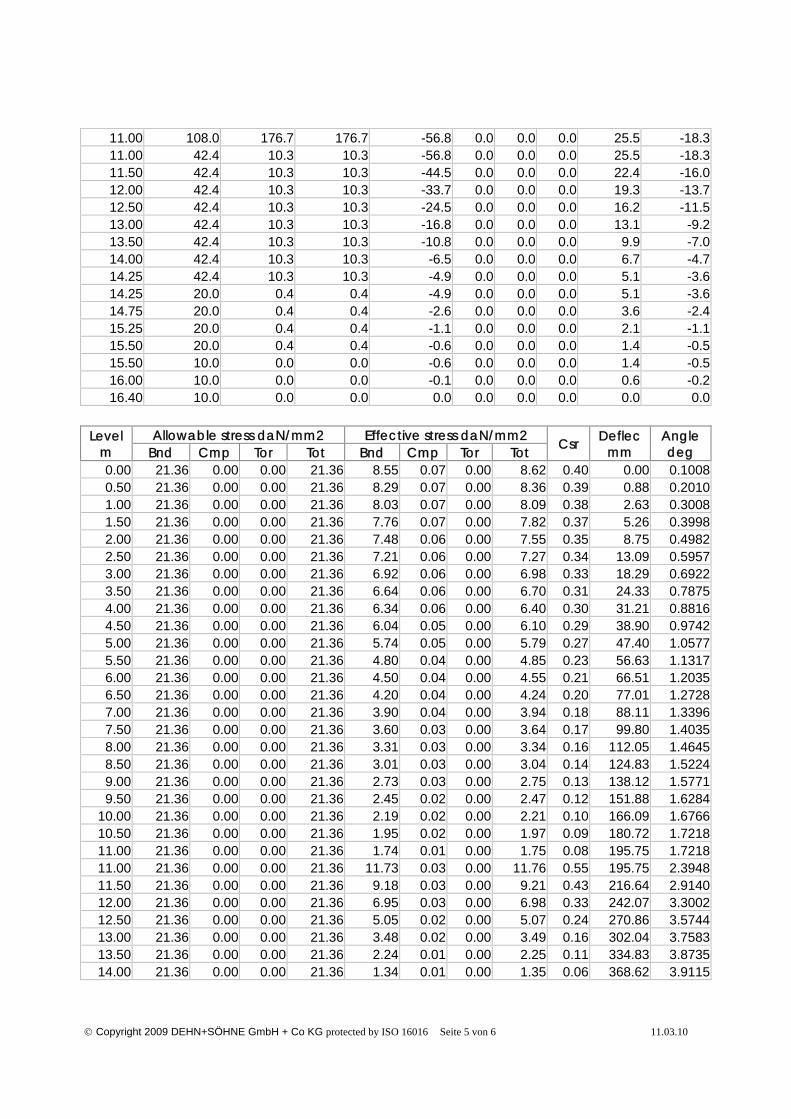
11.00 108.0 176.7 176.7 -56.8 0.0 0.0 0.0 25.5 -18.311.00 42.4 10.3 10.3 -56.8 0.0 0.0 0.0 25.5 -18.311.50 42.4 10.3 10.3 -44.5 0.0 0.0 0.0 22.4 -16.012.00 42.4 10.3 10.3 -33.7 0.0 0.0 0.0 19.3 -13.712.50 42.4 10.3 10.3 -24.5 0.0 0.0 0.0 16.2 -11.513.00 42.4 10.3 10.3 -16.8 0.0 0.0 0.0 13.1 -9.213.50 42.4 10.3 10.3 -10.8 0.0 0.0 0.0 9.9 -7.014.00 42.4 10.3 10.3 -6.5 0.0 0.0 0.0 6.7 -4.714.25 42.4 10.3 10.3 -4.9 0.0 0.0 0.0 5.1 -3.614.25 20.0 0.4 0.4 -4.9 0.0 0.0 0.0 5.1 -3.614.75 20.0 0.4 0.4 -2.6 0.0 0.0 0.0 3.6 -2.415.25 20.0 0.4 0.4 -1.1 0.0 0.0 0.0 2.1 -1.115.50 20.0 0.4 0.4 -0.6 0.0 0.0 0.0 1.4 -0.515.50 10.0 0.0 0.0 -0.6 0.0 0.0 0.0 1.4 -0.516.00 10.0 0.0 0.0 -0.1 0.0 0.0 0.0 0.6 -0.216.40 10.0 0.0 0.0 0.0 0.0 0.0 0.0 0.0 0.0
Allowable stress daN/mm2 Effective stress daN/mm2Levelm Bnd Cmp Tor Tot Bnd Cmp Tor Tot Csr Deflec
mmAngledeg
0.00 21.36 0.00 0.00 21.36 8.55 0.07 0.00 8.62 0.40 0.00 0.10080.50 21.36 0.00 0.00 21.36 8.29 0.07 0.00 8.36 0.39 0.88 0.20101.00 21.36 0.00 0.00 21.36 8.03 0.07 0.00 8.09 0.38 2.63 0.30081.50 21.36 0.00 0.00 21.36 7.76 0.07 0.00 7.82 0.37 5.26 0.39982.00 21.36 0.00 0.00 21.36 7.48 0.06 0.00 7.55 0.35 8.75 0.49822.50 21.36 0.00 0.00 21.36 7.21 0.06 0.00 7.27 0.34 13.09 0.59573.00 21.36 0.00 0.00 21.36 6.92 0.06 0.00 6.98 0.33 18.29 0.69223.50 21.36 0.00 0.00 21.36 6.64 0.06 0.00 6.70 0.31 24.33 0.78754.00 21.36 0.00 0.00 21.36 6.34 0.06 0.00 6.40 0.30 31.21 0.88164.50 21.36 0.00 0.00 21.36 6.04 0.05 0.00 6.10 0.29 38.90 0.97425.00 21.36 0.00 0.00 21.36 5.74 0.05 0.00 5.79 0.27 47.40 1.05775.50 21.36 0.00 0.00 21.36 4.80 0.04 0.00 4.85 0.23 56.63 1.13176.00 21.36 0.00 0.00 21.36 4.50 0.04 0.00 4.55 0.21 66.51 1.20356.50 21.36 0.00 0.00 21.36 4.20 0.04 0.00 4.24 0.20 77.01 1.27287.00 21.36 0.00 0.00 21.36 3.90 0.04 0.00 3.94 0.18 88.11 1.33967.50 21.36 0.00 0.00 21.36 3.60 0.03 0.00 3.64 0.17 99.80 1.40358.00 21.36 0.00 0.00 21.36 3.31 0.03 0.00 3.34 0.16 112.05 1.46458.50 21.36 0.00 0.00 21.36 3.01 0.03 0.00 3.04 0.14 124.83 1.52249.00 21.36 0.00 0.00 21.36 2.73 0.03 0.00 2.75 0.13 138.12 1.57719.50 21.36 0.00 0.00 21.36 2.45 0.02 0.00 2.47 0.12 151.88 1.6284
10.00 21.36 0.00 0.00 21.36 2.19 0.02 0.00 2.21 0.10 166.09 1.676610.50 21.36 0.00 0.00 21.36 1.95 0.02 0.00 1.97 0.09 180.72 1.721811.00 21.36 0.00 0.00 21.36 1.74 0.01 0.00 1.75 0.08 195.75 1.721811.00 21.36 0.00 0.00 21.36 11.73 0.03 0.00 11.76 0.55 195.75 2.394811.50 21.36 0.00 0.00 21.36 9.18 0.03 0.00 9.21 0.43 216.64 2.914012.00 21.36 0.00 0.00 21.36 6.95 0.03 0.00 6.98 0.33 242.07 3.300212.50 21.36 0.00 0.00 21.36 5.05 0.02 0.00 5.07 0.24 270.86 3.574413.00 21.36 0.00 0.00 21.36 3.48 0.02 0.00 3.49 0.16 302.04 3.758313.50 21.36 0.00 0.00 21.36 2.24 0.01 0.00 2.25 0.11 334.83 3.873514.00 21.36 0.00 0.00 21.36 1.34 0.01 0.00 1.35 0.06 368.62 3.9115
© Copyright 2009 DEHN+SÖHNE GmbH + Co KG protected by ISO 16016 Seite 6 von 6 11.03.10
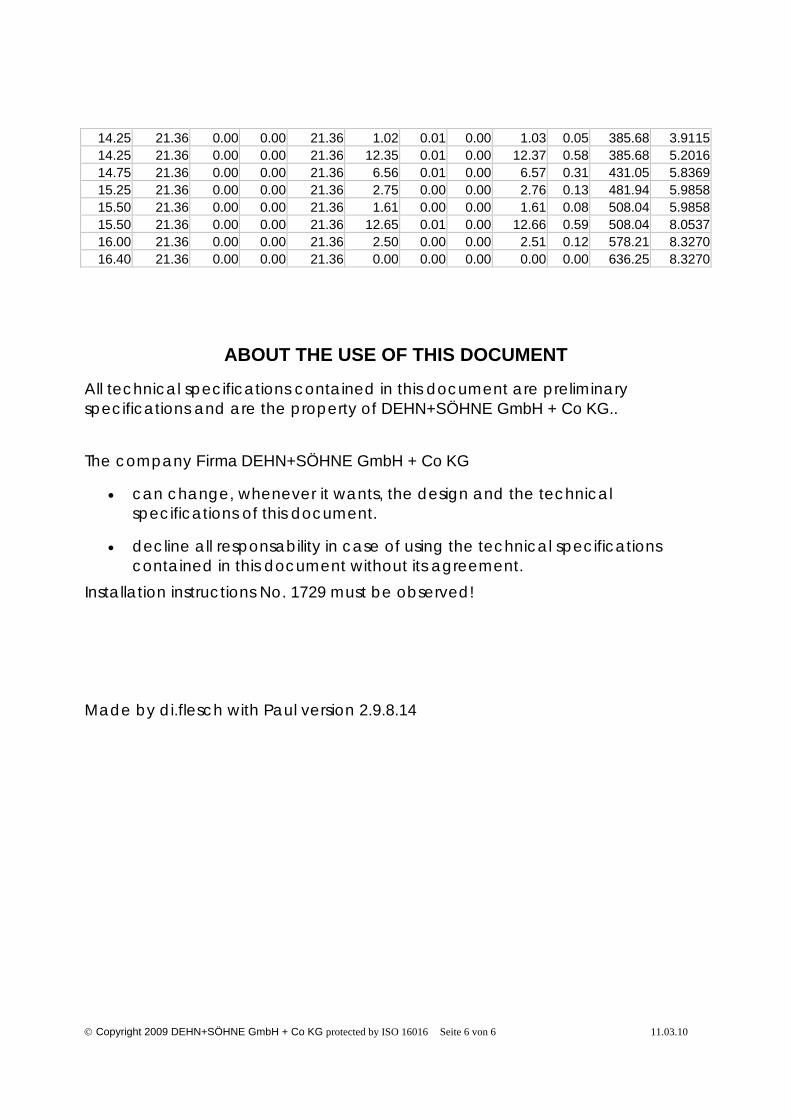
14.25 21.36 0.00 0.00 21.36 1.02 0.01 0.00 1.03 0.05 385.68 3.911514.25 21.36 0.00 0.00 21.36 12.35 0.01 0.00 12.37 0.58 385.68 5.201614.75 21.36 0.00 0.00 21.36 6.56 0.01 0.00 6.57 0.31 431.05 5.836915.25 21.36 0.00 0.00 21.36 2.75 0.00 0.00 2.76 0.13 481.94 5.985815.50 21.36 0.00 0.00 21.36 1.61 0.00 0.00 1.61 0.08 508.04 5.985815.50 21.36 0.00 0.00 21.36 12.65 0.01 0.00 12.66 0.59 508.04 8.053716.00 21.36 0.00 0.00 21.36 2.50 0.00 0.00 2.51 0.12 578.21 8.327016.40 21.36 0.00 0.00 21.36 0.00 0.00 0.00 0.00 0.00 636.25 8.3270
ABOUT THE USE OF THIS DOCUMENT
All technical specifications contained in this document are preliminaryspecifications and are the property of DEHN+SÖHNE GmbH + Co KG..
The company Firma DEHN+SÖHNE GmbH + Co KG
• can change, whenever it wants, the design and the technicalspecifications of this document.
• decline all responsability in case of using the technical specificationscontained in this document without its agreement.
Installation instructions No. 1729 must be observed!
Made by di.flesch with Paul version 2.9.8.14

page1©2010 DEHN + SÖHNE GmbH + Co. KG Hans-Dehn-Str. 1 Postfach 1640 D-92306 Neumarkt, Germany, Tel. +499181 906-700 www.dehn.de, as at: 2010-03-02
Telescopic Lightning Protection Mast in Bucket or Concrete Foundation
Air-termination mast for protection against direct lightning strike of systems such as biogasplants, PV systems on exposed sites, Ex systems, ammunition dumps.
Technical data to part no.: 103 013
Material St/tZn
Height above floor (L1) 13.35 m
Mast segments 2
Length of air-termination rod (L2) 2400 mm
Dimension of flange plate 400x400 mm
Type of flange plate 4xØ28 für 4xM24 (300x300) mm
Dimension of concrete foundation on site (axbxc) 1400x1400x900 mm
Standard DIN EN 50164-(1+2)
Weight approx. 228 kg
Ordering information
Type Part No. Packing unit
Telescopic Lightning Protection Mast in Bucketor Concrete Foundation
103 013 1 pce
For further information please see installation instructions No. 1729.
We reserve the right to modify design, technology, dimensions, weights and materials according to technical progress. Illustrations are non-binding. Pictures may differ from the modules described.
page1©2010 DEHN + SÖHNE GmbH + Co. KG Hans-Dehn-Str. 1 Postfach 1640 D-92306 Neumarkt, Germany, Tel. +499181 906-700 www.dehn.de, as at: 2010-03-02
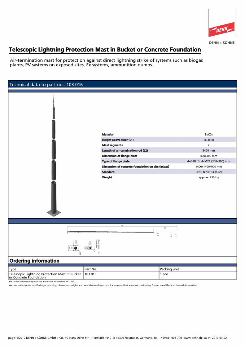
Telescopic Lightning Protection Mast in Bucket or Concrete Foundation
Air-termination mast for protection against direct lightning strike of systems such as biogasplants, PV systems on exposed sites, Ex systems, ammunition dumps.
Technical data to part no.: 103 016
Material St/tZn
Height above floor (L1) 16.35 m
Mast segments 2
Length of air-termination rod (L2) 5400 mm
Dimension of flange plate 400x400 mm
Type of flange plate 4xØ28 für 4xM24 (300x300) mm
Dimension of concrete foundation on site (axbxc) 1400x1400x900 mm
Standard DIN EN 50164-(1+2)
Weight approx. 230 kg
Ordering information
Type Part No. Packing unit
Telescopic Lightning Protection Mast in Bucketor Concrete Foundation
103 016 1 pce
For further information please see installation instructions No. 1729.
We reserve the right to modify design, technology, dimensions, weights and materials according to technical progress. Illustrations are non-binding. Pictures may differ from the modules described.
page1©2010 DEHN + SÖHNE GmbH + Co. KG Hans-Dehn-Str. 1 Postfach 1640 D-92306 Neumarkt, Germany, Tel. +499181 906-700 www.dehn.de, as at: 2010-03-10
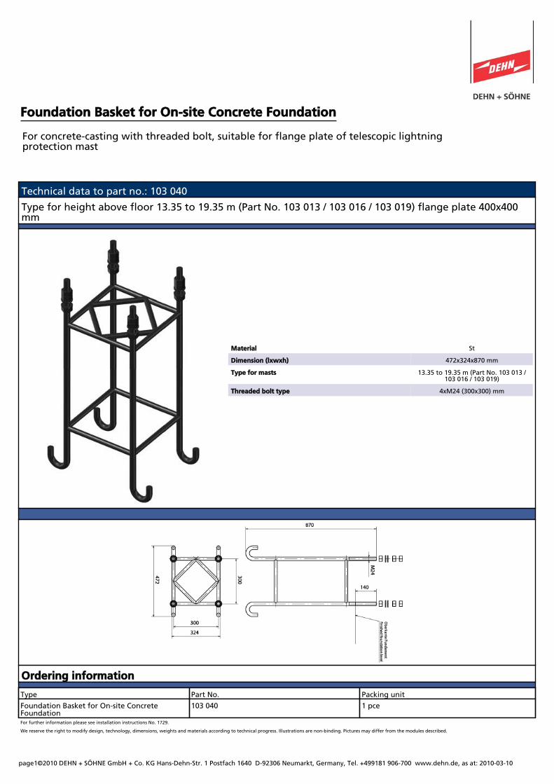
Foundation Basket for On-site Concrete Foundation
For concrete-casting with threaded bolt, suitable for flange plate of telescopic lightningprotection mast
Technical data to part no.: 103 040
Type for height above floor 13.35 to 19.35 m (Part No. 103 013 / 103 016 / 103 019) flange plate 400x400mm
Material St
Dimension (lxwxh) 472x324x870 mm
Type for masts 13.35 to 19.35 m (Part No. 103 013 /103 016 / 103 019)
Threaded bolt type 4xM24 (300x300) mm
Ordering information
Type Part No. Packing unit
Foundation Basket for On-site ConcreteFoundation
103 040 1 pce
For further information please see installation instructions No. 1729.
We reserve the right to modify design, technology, dimensions, weights and materials according to technical progress. Illustrations are non-binding. Pictures may differ from the modules described.
page1©2010 DEHN + SÖHNE GmbH + Co. KG Hans-Dehn-Str. 1 Postfach 1640 D-92306 Neumarkt, Germany, Tel. +499181 906-700 www.dehn.de, as at: 2010-03-10
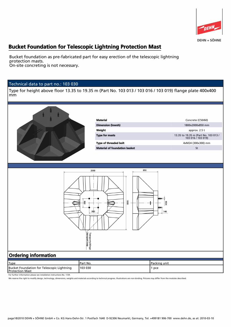
Bucket Foundation for Telescopic Lightning Protection Mast
Bucket foundation as pre-fabricated part for easy erection of the telescopic lightningprotection masts.On-site concreting is not necessary.
Technical data to part no.: 103 030
Type for height above floor 13.35 to 19.35 m (Part No. 103 013 / 103 016 / 103 019) flange plate 400x400mm
Material Concrete (C50/60)
Dimension (lxwxh) 1800x2000x850 mm
Weight approx. 2.5 t
Type for masts 13.35 to 19.35 m (Part No. 103 013 /103 016 / 103 019)
Type of threaded bolt 4xM24 (300x300) mm
Material of foundation basket St
Ordering information
Type Part No. Packing unit
Bucket Foundation for Telescopic LightningProtection Mast
103 030 1 pce
For further information please see installation instructions No. 1729.
We reserve the right to modify design, technology, dimensions, weights and materials according to technical progress. Illustrations are non-binding. Pictures may differ from the modules described.
COURTESY TRANSLATION
Type Test Test report No. 1
Subject Matter: Prefabricated Pocket Foundations HG 18/20 and HG 24/24 Ordering Party: Bartram Bau-System Postfach 1261 24591 Hohenwestedt and Klebl GmbH Postfach 1380 92303 Neumarkt Originator of the Structural Documents: Dr.-Ing. H. Schwing Postfach 1308 64345 Griesheim Period of Validity: until 11.05.2012 According to the documents listed under No. 1 the pocket-foundations HG 18/20 and HG 24/24 were tested with regard to stability.
1 Test Documents 1.1 Tested Documents
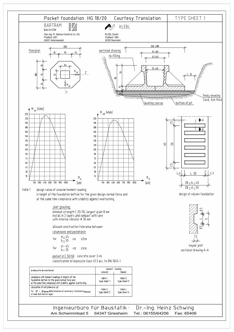
1.1.1 Original Calculation of Pocket Foundation HG 18/20 (to be found in the test reports of the
“Hessische Landesprüfstelle für Baustatik” with file reference 64a08 – 212/75, latest extension with period of validity until 31.10.2006).
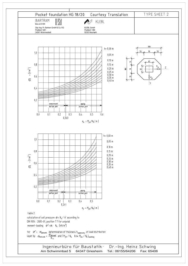
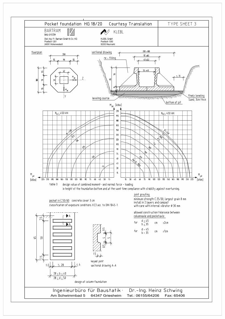
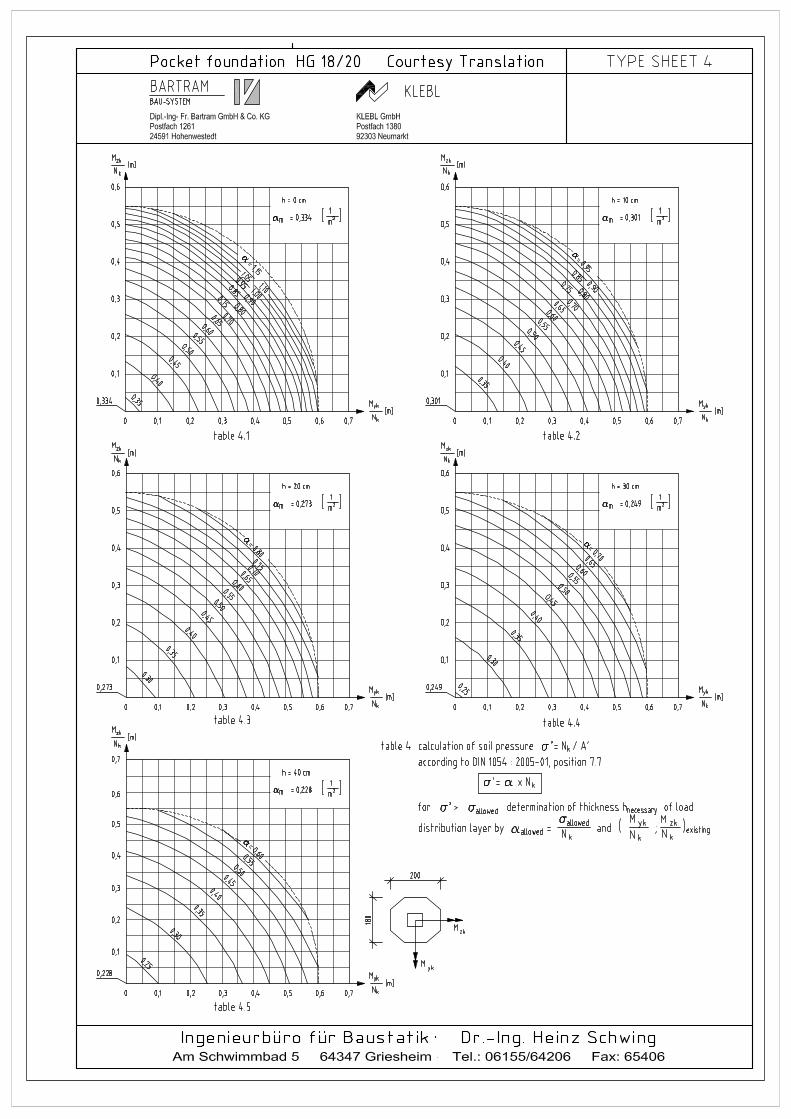
1.1.1.1 Structural calculation dated 1.10.1976, 89 pages (Title sheet, contents, pages I-IV, 1.01-1.53, 2.01-2.30 without attachments 1-7 and type sheets 1 and 2) 1.1.1.2 Amendment to calculation dated 5.1.1977, 21 pages (Title sheet, pages 2-12) 1.1.1.3 Second amendment to calculation dated December 1983, 12 pages (Title sheet, pages 2-12) 1.1.2 Adaptation HG 18/20 (adaptation according to DIN 1045-1:2001-07) (Title sheet, pages 2-12) 1.1.2.1 Additional calculation dated January 2007, 8 pages (Title sheet, pages II - VIII) 1.1.2.2 Type sheets, 4 pages DIN A 3 Uniaxial bending and normal force loading Type sheet 1 – table 1: layout plan, sectional drawing, design of column base, design diagrams Type sheet 2 – table 2: Evaluation of soil pressure / thickness of load distribution layer Biaxial bending and normal force loading Type sheet 3 – table 3.1: design diagrams Type sheet 4 – table 4: Evaluation of soil pressure / thickness of load distribution layer 1.1.2.3 Design drawings: 1 plan (formwork and structural drawing, prefabricated pocket foundation HG 18/20) 1.1.3 Original Calculation of Pocket Foundation HG 24/24 (to be found in the test reports of the
“Hessische Landesprüfstelle für Baustatik” type test with file reference 64a08 – 37/77, latest extension with period of validity until 31.10.2006).
1.1.3.1 Structural calculation dated 31.01.1977, 153 pages (Title sheet, pages I-IV, 0.01-0.04, 1.01-1.21, 2.01-2.19, 3.01-3.11, 4.04-4-74, 5.01-5.04, 6.01-6.07, 7.01-7.06, 8.01-8.02) 1.1.3.2 Attachment 3.1 to electronically calculation, 8 pages (Overview, pages 1-7) 1.1.3.3 Amendment to calculation dated December 1983, 11 pages (Title sheet, pages 2-11)
1.1.4 Adaptation HG 24/24 (adaptation according to DIN 1045-1:2001-07) 1.1.4.1 Additional calculation dated October 2006, 7 pages (Title sheet, pages 2-7) 1.1.4.2 Type sheets, 7 pages DIN A 3 and 1 page DIN A 4 Type sheet 1: layout plan, sectional drawing, building of column base Uniaxial bending and normal force loading Type sheet 2.1 – table 1: Design diagrams Type sheet 2.2 – table 2: Evaluation of soil pressure / thickness of load distribution layer Biaxial bending and normal force loading Type sheet 3.1 – table 3.1 (column 30/30), table 3.2 (column 30/35), table 3.3 (column 30/40): design diagrams Type sheet 3.2 – table 3.4 (column 35/35), table 3.5 (column 30/45), table 3.6 (column 35/40): design diagrams Type sheet 3.3 – table 3.7 (column 35/45), table 3.8 (column 40/40): design diagrams Type sheet 3.4 – table 3.9 (column 30/50), table 3.10 (column 35/50, 40/45, 40/50, 45/45, 45/50, 50/50): design diagrams 1.1.4.3 Design drawings: 1 plan (formwork and structural drawing, prefabricated pocket foundation HG 24/24) 1.2 Other Documents: 1.2.1 Test reports belonging to the documents Nr. 1.1.1 and 1.1.3 of the “Hessische
Landesprüfstelle für Baustatik, 64293 Darmstadt” – type test with reference number 64a08-212/75 and 64a08-37/77, latest extension with validity period until 31.10.2006.
1.2.2 Report (Rapport 76:1, dated 11.3.1976) of the “Institut für Konstruktionstechnik der Abteilung
Betonbau” at the “Technische Hochschule Chalmers” in Göteburg about the documented evidence of conformity of the normal force crossover from a prefabricated concrete column into a pocket-foundation.
1.2.3 Report (Rapport 76:6) of the “Institut für Konstruktionstechnik der Abteilung Betonbau” at the
“TH Chalmers” in Göteburg about experiments for the determination of the load bearing behaviour of the pocket-foundation under bending and normal force loading.
1.2.4 Translation of Nr. 1.2.3 from Swedish. 1.2.5 Expert evaluation W 212 to No. 1.3.2, by Prof.-Dr.-Ing. Weigler, “Institut für Massivbau” of the “Technische Hochschule Darmstadt”, dated. 1.4.1976.
1.3 Basic Documents: Valid technical regulations, especially: DIN 1045-1 Structures of concrete, reinforced concrete, prestressed concrete Part 1, edition July 2001 DIN 1055 Part 1, edition 2002-06 DIN 1055-100 Effects on structures Part 100, edition March 2001 DIN 1054 Verification of the safety of earthworks and foundations edition January 2005 2 Specification
The pocket-foundations consist of prefabricated reinforced concrete foundation (prefabricated en bloc) with special design. They consist of an octagonal floor plate, of a molded pocket with reinforced ring anchor on the top and two triangular reinforcement wings on each corner. The floor plate has inclined chards at the reinforced wings and also at the exterior side of the pockets. Pocket-foundation HG 18/20: Horizontal projection measurements 180 cm/200cm, 85 cm total height, 15 cm thickness of floor plate for column measurements 28 cm / 28 cm – 40 cm/50 cm Load categories up to Nd = 1050 kN, allowed characteristic bottom pressure on the reduced foundation surface σ’ = 285 kN/m²
Pocket-foundation HG 24/24: Horizontal projection measurements 240 cm/240cm, 101 cm total height, 20 cm thickness of floor plate for column measurements 30 cm/30 cm – 50 cm/50 cm Load categories up to Nd = 1950 kN, allowed characteristic bottom pressure on the reduced foundation surface σ’ = 305 kN/m²
3 Load Assumption
Subject-matter of the type test are the pocket-foundations under the impact of the design value of the columns. The design values which can be adjusted by the foundations are listed in the type sheets belonging to the pocket-foundations. The sizes of the sectional drawings which are disclosed in the tables of the pocket-foundations (Nd, Myd, Mzd) are in accordance with the design values to the tune of the balance point of the foundation surface area.
4 Materials
4.1 Concrete class C 50/60, exposure class XC3 C 25/30 for the grouting concrete. 4.2 Reinforcing steel BSt 500
5 Soil and Underground Water Conditions In accordance with the preliminaries for the foundation soil (DIN 1054:2001-01, No. 7.7 (“….levelled surface, sufficient soil resistance up to a depth under foundation base which matches the 2x foundation width…”) the foundation HG 18/20 is designed for a foundation pressure of 285 kN/m² and the foundation HG 24/24 is designed for a foundation pressure of 305 kN/m² (characteristic foundation pressure on the reduced foundation surface area; this is to be determined by taking the design values of the pocket-foundations divided by 1.5). In order to comply with the permissible soil pressure a sand or mortar layer up to a thickness of 40 cm between the soil base and the prefabricated pocket-foundation may be installed.
6 Test Results The documents mentioned under no. 1.1 had been proofed with regard to structural safety, but not with regard to other construction regulations or other official requirements. They are in accordance with the presently valid technical regulations. There are no objections regarding static construction against the building of the prefabricated pocket-foundations after having proofed the documents.
7 Special Remarks
7.1 The documents which are type-proofed include the certificate for the load bearing capacity
according to DIN 1045-1:2001-07 including safety against overturning (DIN 1054:2005-01) In special cases It might be necessary to provide further evidence in relation to soil conditions.
7.2 Necessary certificates for the prefabricated columns for the pockets, the length of the fastening
of the column reinforcement, the maximum cross load in the column are to be provided separately.
7.3 Certificates for the erection and the transport are not matter of this type test. 7.4 Special regulations of the respective federal construction law are to be followed in accordance
with design and construction.
8 Necessary Documents for the Building Application on a Case-to-Case-Basis
1. Present test report no. 1, S-WUE/060308
2. Type documents for the appropriate type of foundation according to no. 1.1.2.2 respectively no.
1.1.4.2
3. General construction drawings
9 General Remarks
9.1 This structural type test does not release the principal from the obligation to get a building
permit unless the valid construction law or other regulations release him in general. 9.2 This structural type test releases the construction supervisory board from a second structural
test of the calculation documents, but not from the responsibility to proof the conformity of the construction work with the preliminaries and results of the tested documents.
9.3 The tested documents may only be used and/or published as in the original version verified by
the proofing authority. In questionable cases the documents which are to be found at the Prüfamt für Baustatik are decisive.
9.4 Period of validity of this type test may be extended up to 5 years when applied for. 9.5 In case of essential changes before expiration of validity regarding the following:
- Structural matters - Type of use - The technical regulations, approvals or construction and technical findings which
are basis for this structural type test
the owner of the type test has to inform the Prüfamt für Baustatik. This bureau will decide about further proceedings.
COURTESY TRANSLATION
Prolongation Note for Type Test S-WUE/060308, dated 11 May 2007
Subject Matter: Prefabricated Pocket Foundations HG 18/20 and HG 24/24 Ordering Party: Bartram Bau-System Postfach 1261 24591 Hohenwestedt and Klebl GmbH Postfach 1380 92303 Neumarkt Originator of the Structural Documents: Dr.-Ing. H. Schwing Postfach 1308 64345 Griesheim Period of Validity: until 26.04.2015 The documents listed under No. 1 Type Test Report S-WUE/060308 were proofed to be in compliance with the established Technical Building Regulations and were marked with an indorsement. This prolongation note will only be valid in connection with the above named Type Test Report.