Embed Size (px)
Citation preview

University of Arizona J. H. Burge
1
Static Equilibrium Static Equilibrium Definition: When forces acting on an object which is at rest are balanced, then the object is in a state of static equilibrium.
- No translations - No rotations
In a state of static equilibrium, the resultant of the forces and moments equals zero. That is, the vector sum of the forces and moments adds to zero.

University of Arizona J. H. Burge
2
Tolerances for optics are very tight. We need to support them so they are accurately located. If forces are applied, we want to determine: Motion Distortion In order to do this, we need to evaluate the system, including the applied forces and the reaction forces. In this section, we define forces and moments, develop the free body diagram, and use the

University of Arizona J. H. Burge
3
equations of static equilibrium to solve for reaction forces and moments. Forces are vectors:
They have a magnitude and direction. What does a force do? Can accelerate an object F = m a Can stretch a spring scale
Forces can be applied: Units of Pounds on Newtons 1 pound (lbF)= 4.45 N : 1 N = 0.22 lb Or they can come for gravity
W = m g (g = 9.8 m/s2 = 386 in/s2) 1 kg has weigh of 9.8 N or 2.2 lbs 1 lbM is the mass that weighs 1 pound 1 slug weighs 32.2 lbs

University of Arizona J. H. Burge
4
The moment is defined as
Also called “torque” Units are in-lb or N-m
1 N-m = 8.84 in-Lb Moments are “twisting forces”. They make things rotate
sinA AB B
AB B
AB
B
M r F
r Fr Fr F
θ
⊥
⊥
= ×
== ⋅= ⋅

University of Arizona J. H. Burge
5
Defining moment from applied force
A
B
ABr
BF
A AB BM r F= ×
A
B
ABr
BF
A
B
ABr
BF
sinAB BA r FM θ=
A
ABr
BF
ABA r FM ⊥⋅=
sinF F⊥ =
θ
sinABr r θ⊥ =
A r FM ⊥ ⋅=
θ

University of Arizona J. H. Burge
6
Force couples
Two forces, equal and opposite in direction, which do not act in the same line cause a pure moment
d
F
M = F d F
d
F
M = F d
F
University of Arizona J. H. Burge
7
Simple cases
Cable
Can only transmit tension along direction of cable
No compression
No moment
No lateral force

University of Arizona J. H. Burge
8
Constraints Constraints are attachment points that will maintain their position.
Idealization of 2D supports

University of Arizona J. H. Burge
9
Idealization of 3D supports

University of Arizona J. H. Burge
10
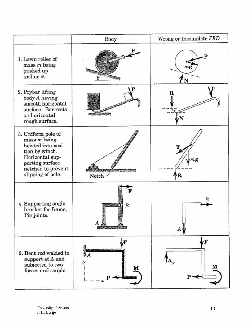
Free Body Diagrams
Step 1. Determine which body or combination of bodies is to be isolated. The body chosen will usually involve one or more of the desired unknown quantities.
Step 2. Next, isolate the body or combination of bodies chosen with a diagram that represents its complete external boundaries.
Step 3. Represent all forces that act on the isolated body as applied by the removed contacting bodies in their proper positions in the diagram of the isolated body. Do not show the forces that the object exerts on anything else, since these forces do not affect the object itself.
Step 4. Indicate the choice of coordinate axes directly on the diagram. Pertinent dimensions may also be represented for convenience. Note, however, that the free-body diagram serves the purpose of focusing accurate attention on the action of the external forces; therefore, the diagram should not be cluttered with excessive information. Force arrows should be clearly distinguished from other arrows to avoid confusion.
When these steps are completed a correct free-body diagram will result. Now, the appropriate equations of equilibrium may be utilized to find the proper solution.

University of Arizona J. H. Burge
11
University of Arizona J. H. Burge
12
University of Arizona J. H. Burge
13

University of Arizona J. H. Burge
14

University of Arizona J. H. Burge
15
For a rigid body to be static, the net sum of forces and moments acting on it must be zero.
0F =∑
0
0
0
x
y
z
F
F
F
=
=
=
∑∑∑
0M =∑
0
0
0
x
y
z
M
M
M
=
=
=
∑∑∑
In general six equations, in the plane this reduces to 3
0
0
0
x
y
F
F
M
=
=
=
∑∑∑

University of Arizona J. H. Burge
16
Solving Statics problems Determine reaction forces for static equilibrium.
1.Draw Free Body Diagram Decide if the problem is solvable
a. How many unknowns? b.How many equations can you write?
2.Write equations to sum forces and moments to be 0
a. Use reaction forces as unknowns b.Be smart about coordinates and
choice of points for summing moments
3.Solve equations for reaction forces 4.Check your answer and the direction

University of Arizona J. H. Burge
17
2D Particle Example
• Determine magnitude of F2 and F3

University of Arizona J. H. Burge
18
Link Pin joint at both ends
Equilibrium requires that the forces be equal, opposite and collinear.
Therefore, for this member Ay = By = 0
Pin joint will not transmit a moment

University of Arizona J. H. Burge
19
Simple Examples Determine reaction forces and moments: Simple support Cantilever
a b
L
B
F
A
F

University of Arizona J. H. Burge
20
X and Y components Cantilever
L
F
45°

University of Arizona J. H. Burge
21
Reaction from moments
M
L
F
F
a

University of Arizona J. H. Burge
22

University of Arizona J. H. Burge
23
Example: Hanging a mass, using a pulley
1 kg
θ

University of Arizona J. H. Burge
24
2D Pulley Example
Specifications:
• Mass of block A = 22 kg • Mass of block B = 34 kg
Assumptions: • Pulleys are frictionless • Block A is free to roll • Cable system is continuous
Determine: • Displacement “y” for equilibrium

University of Arizona J. H. Burge
25
3D Cable System Example
Specifications: • Weight of plate = 250 lb
Assumptions: • Plate is homogeneous
Determine: • Force in each supporting cable
Use direction cosines

University of Arizona J. H. Burge
26
Overconstraint Each body has a total of 6 degrees of freedom that define its position Such as x, y, z, θx, θy , θz These lead to 6 Equations that can be used to solve for reaction forces:
∑Fx = 0 ∑Fy = 0 ∑Fz = 0
∑Mx = 0 ∑My = 0 ∑Mz = 0
If the mechanical constraints provide an attachment so that one or more degrees of freedom are free, the body is underconstrained

University of Arizona J. H. Burge
27
If the mechanical constraints provide an attachment so that there is no unique solution for the reaction forces, the body is overconstrained A body that is neither overconstrained nor underconstrained is called static determinant Static equations must have 6 unknowns for 3-space, or 3 unknowns for in-plane

University of Arizona J. H. Burge
28
If you are not sure, then try solving for the reaction forces and moments. If you have a unique solution
static determinant If you have multiple solutions (more unknowns than equations) Overconstrained reaction forces can be pushing against each other If you have more equations than unknowns Underconstrained
Some degree of freedom is not constrained and could move
Try to figure out what degree of freedom has not been constrained.
You can be overconstrained and
underconstrained at the same time!

University of Arizona J. H. Burge
29
Frames
• Designed to support loads. • Typically rigid, stationary and fully constrained. • Contains at least one multi-force member.
Machines
• Designed to transmit or modify forces. • Contain moving parts. • Contains at least one multi-force member.
University of Arizona J. H. Burge
30
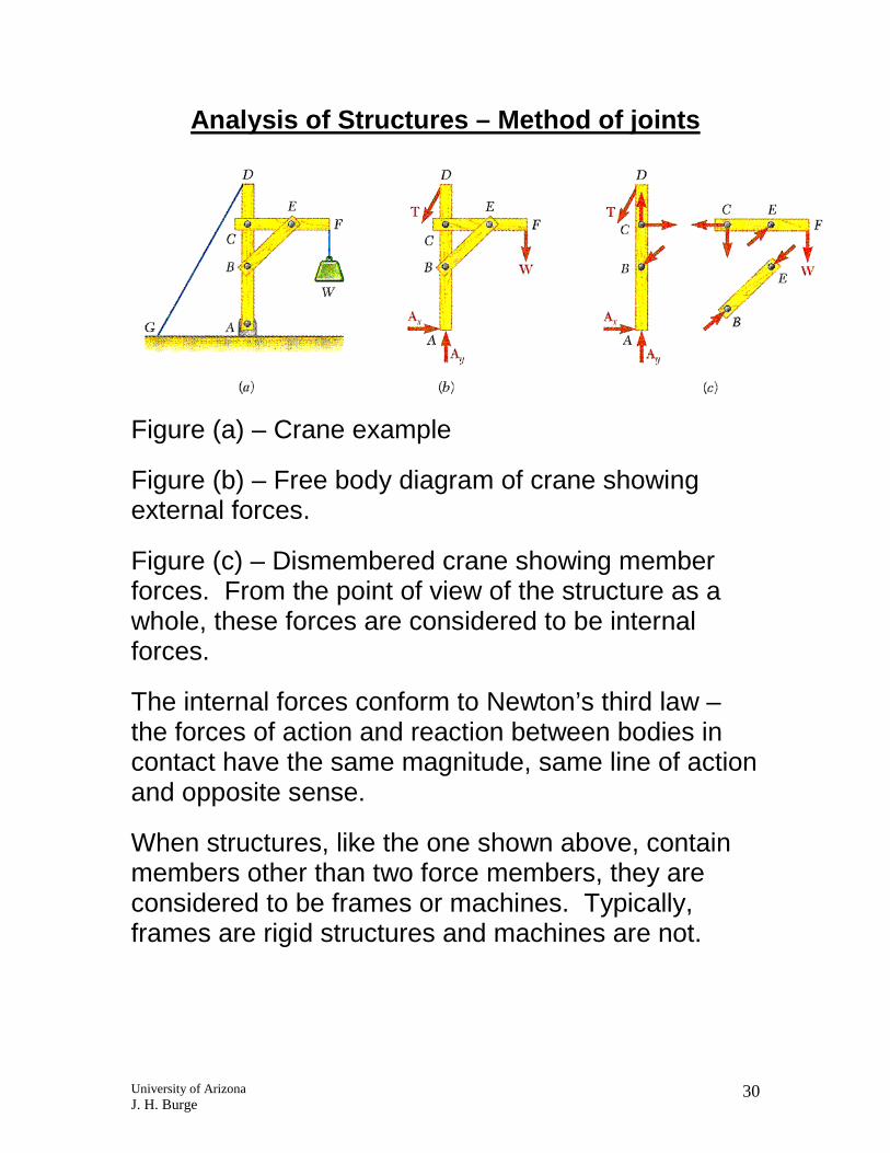
Analysis of Structures – Method of joints
Figure (a) – Crane example
Figure (b) – Free body diagram of crane showing external forces.
Figure (c) – Dismembered crane showing member forces. From the point of view of the structure as a whole, these forces are considered to be internal forces.
The internal forces conform to Newton’s third law – the forces of action and reaction between bodies in contact have the same magnitude, same line of action and opposite sense.
When structures, like the one shown above, contain members other than two force members, they are considered to be frames or machines. Typically, frames are rigid structures and machines are not.

University of Arizona J. H. Burge
31
Analysis of structures – Method of sections Divide structure along sections, rather than joints. Solve for equilibrium.
The equation summing forces in the Y direction only has one unknown because all cut members except A-B are horizontal.
Because T2 is positive, member A-B is in 1133N of tension

University of Arizona J. H. Burge
32
Assuming the beam does not fall, what is the direction of the force applied to the beam at C?

University of Arizona J. H. Burge
33
Example
Determine the forces acting on member ABCD.