Embed Size (px)
Citation preview
Statics
Chapter 7
Internal Forces
Eng. Iqbal Marie
Hibbeler, Engineering Mechanics: Statics,12e, Prentice Hall
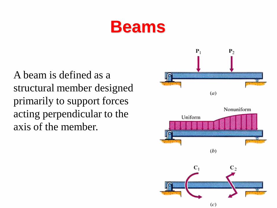
Beams
A beam is defined as a
structural member designed
primarily to support forces
acting perpendicular to the
axis of the member.
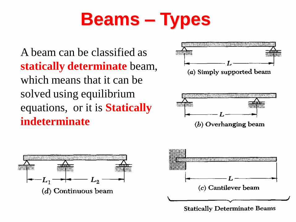
Beams – Types
A beam can be classified as
statically determinate beam,
which means that it can be
solved using equilibrium
equations, or it is Statically
indeterminate
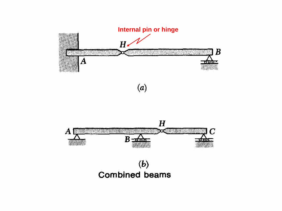
Internal pin or hinge
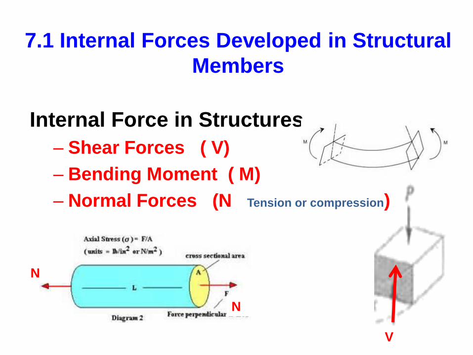
7.1 Internal Forces Developed in Structural
Members
Internal Force in Structures
– Shear Forces ( V)
– Bending Moment ( M)
– Normal Forces (N Tension or compression)
N
N
V
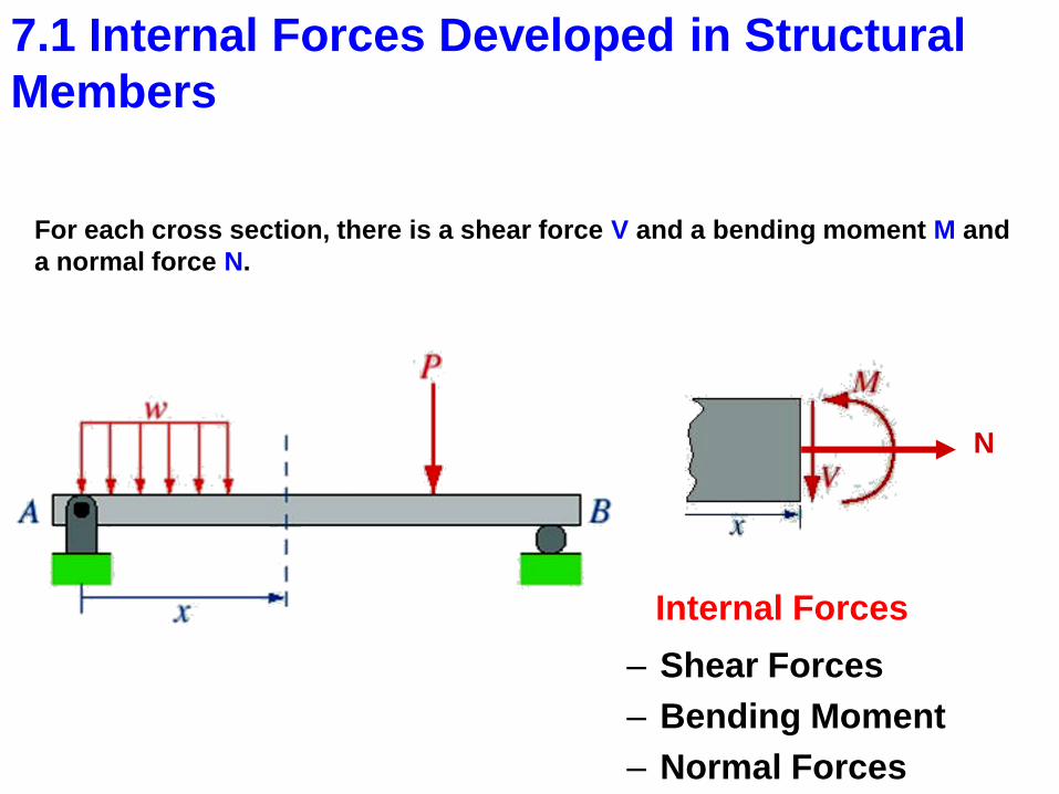
For each cross section, there is a shear force V and a bending moment M and
a normal force N.
Internal Forces
N
– Shear Forces
– Bending Moment
– Normal Forces
7.1 Internal Forces Developed in Structural
Members
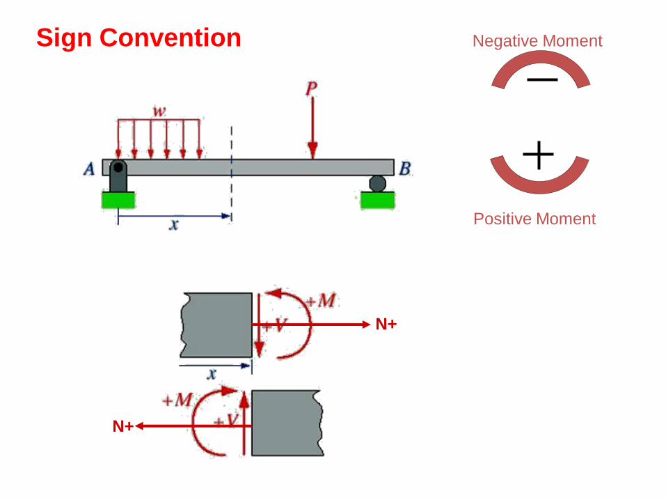
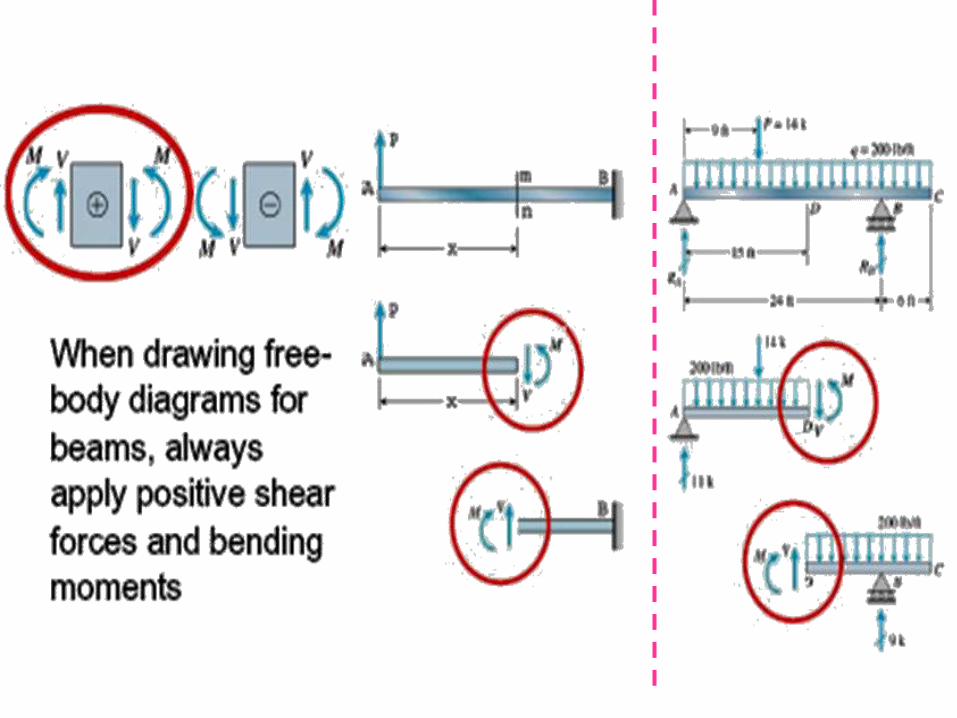
Sign Convention
N+
N+
Negative Moment
Positive Moment
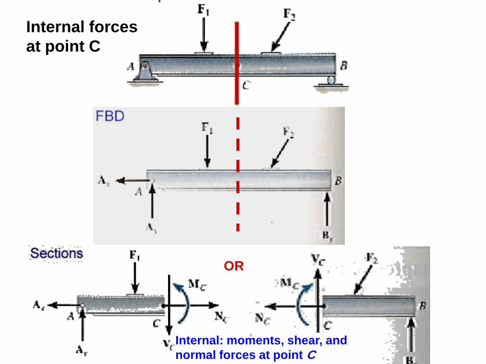
Internal forces
at point C
OR
Internal: moments, shear, and
normal forces at point C
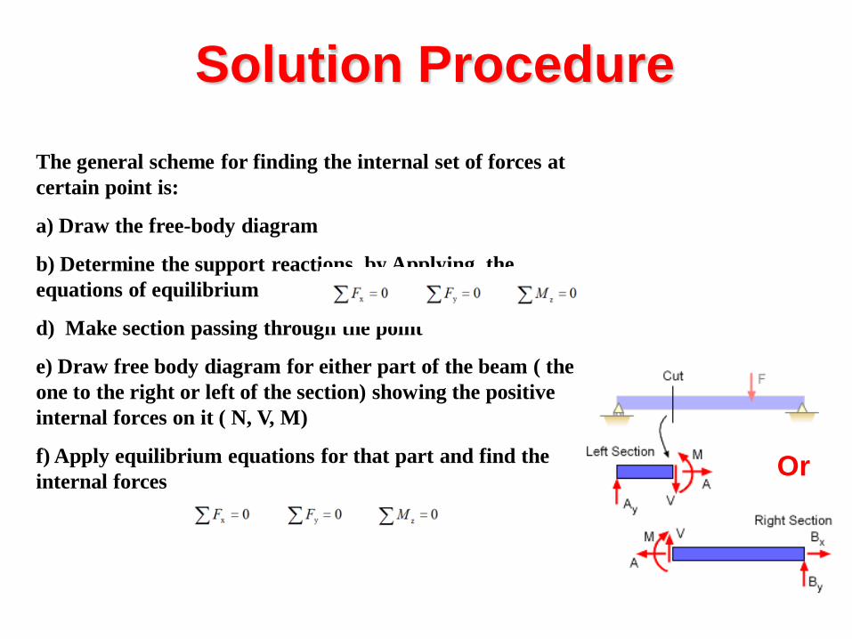
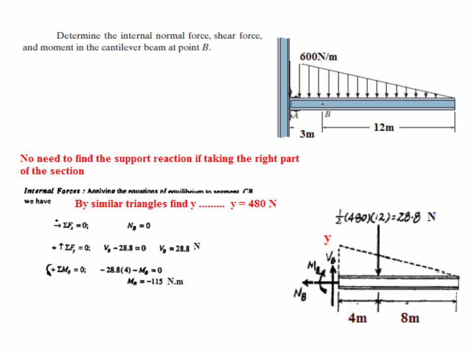
Solution Procedure
The general scheme for finding the internal set of forces at
certain point is:
a) Draw the free-body diagram
b) Determine the support reactions by Applying the
equations of equilibrium
d) Make section passing through the point
e) Draw free body diagram for either part of the beam ( the
one to the right or left of the section) showing the positive
internal forces on it ( N, V, M)
f) Apply equilibrium equations for that part and find the
internal forces
Or
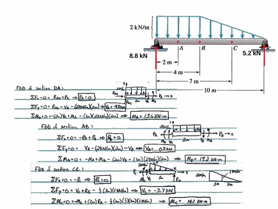
8.8 kN 5.2 kN
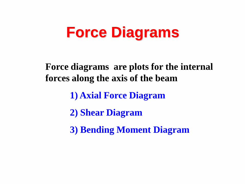
Force Diagrams
Force diagrams are plots for the internal
forces along the axis of the beam
1) Axial Force Diagram
2) Shear Diagram
3) Bending Moment Diagram
y By D
By D
B D
D
By
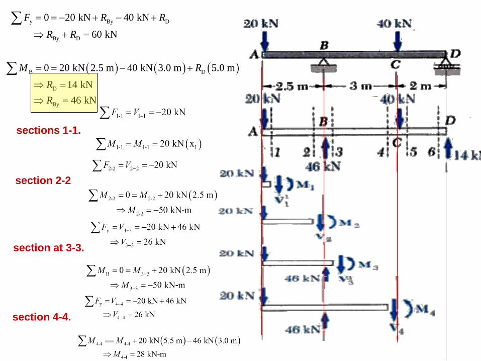
0 20 kN 40 kN
60 kN
0 20 kN 2.5 m 40 kN 3.0 m 5.0 m
14 kN
46 kN
F R R
R R
M R
R
R
sections 1-1.
section 2-2
section at 3-3.
section 4-4.
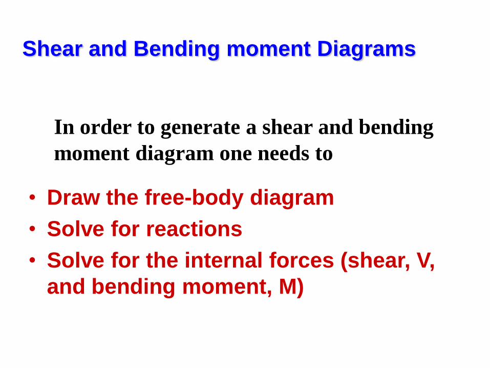
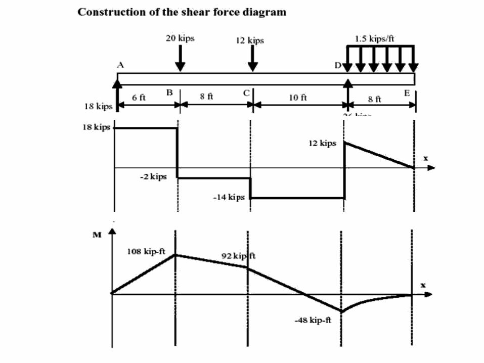
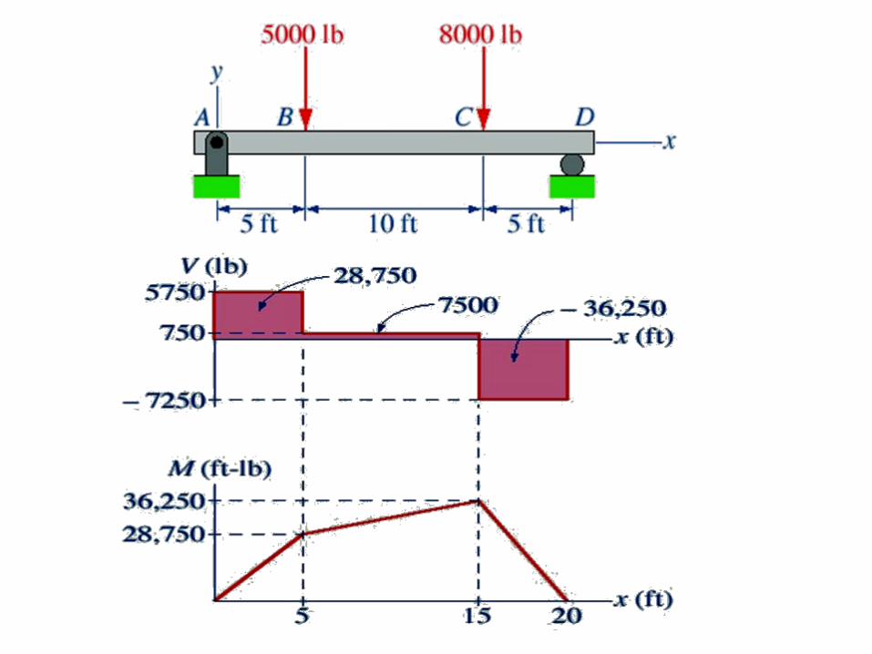
Shear and Bending moment Diagrams
• Draw the free-body diagram
• Solve for reactions
• Solve for the internal forces (shear, V,
and bending moment, M)
In order to generate a shear and bending
moment diagram one needs to
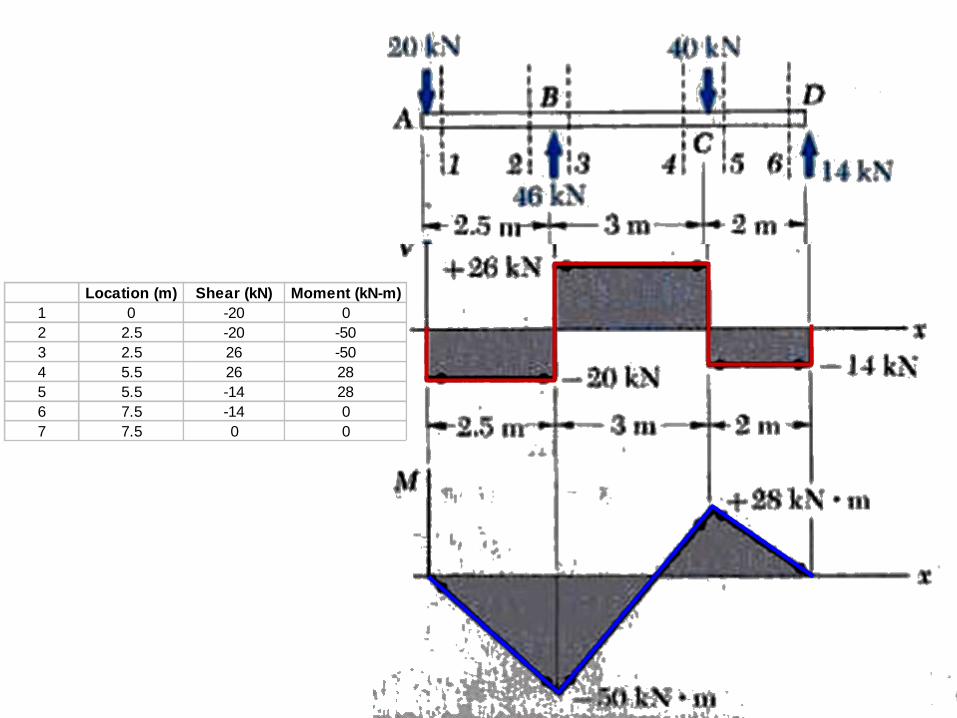
Location (m) Shear (kN) Moment (kN-m)
1 0 -20 0
2 2.5 -20 -50
3 2.5 26 -50
4 5.5 26 28
5 5.5 -14 28
6 7.5 -14 0
7 7.5 0 0
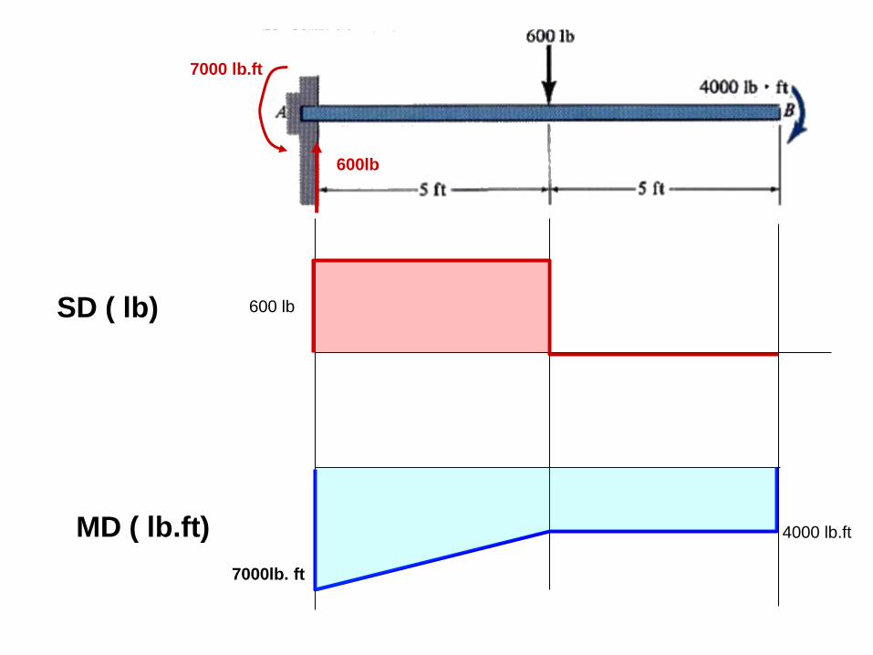
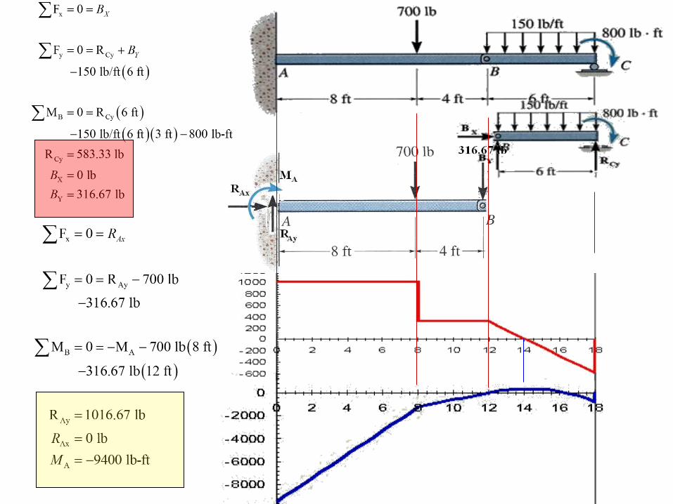
600lb
7000 lb.ft
600 lb
7000lb. ft
4000 lb.ft MD ( lb.ft)
SD ( lb)
V (k)
M (k.ft)
V (k)
M (k.ft)
w (k/ft)
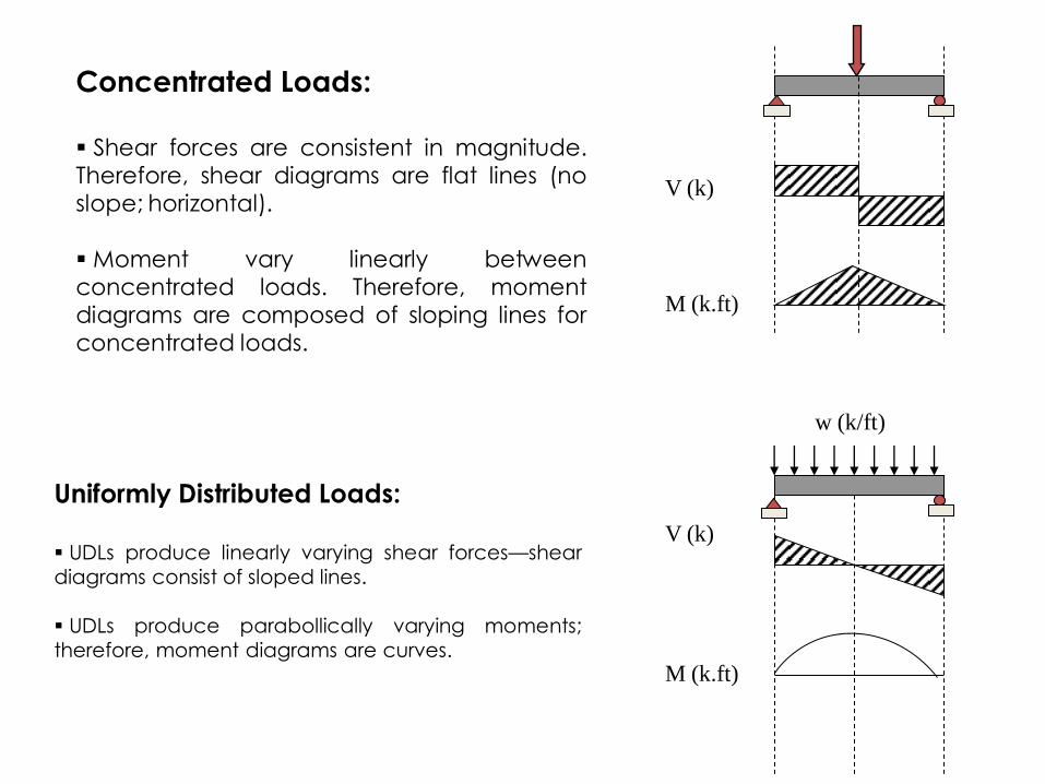
Concentrated Loads:
Shear forces are consistent in magnitude. Therefore, shear diagrams are flat lines (no slope; horizontal). Moment vary linearly between concentrated loads. Therefore, moment diagrams are composed of sloping lines for concentrated loads.
Uniformly Distributed Loads:
UDLs produce linearly varying shear forces—shear
diagrams consist of sloped lines.
UDLs produce parabollically varying moments;
therefore, moment diagrams are curves.
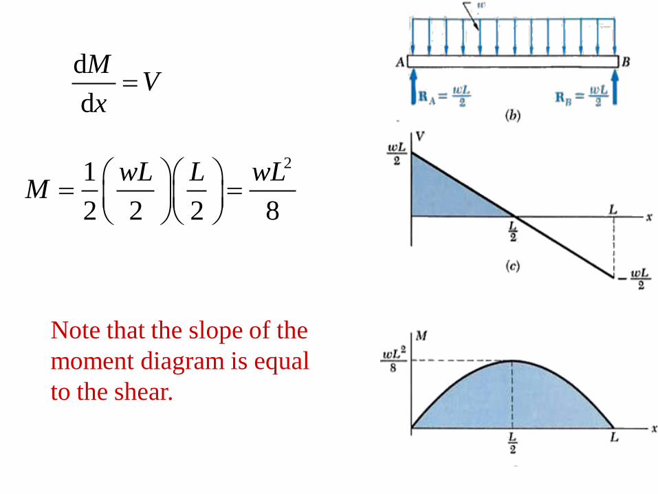
d
d
MV
x
21
2 2 2 8
wL L wLM
Note that the slope of the
moment diagram is equal
to the shear.
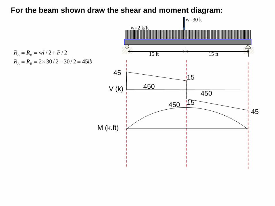
w=2 k/ft
15 ft 15 ft
w=30 k
45
V (k)
M (k.ft)
15
15
45
450 450
450
lbRR
PwlRR
BA
BA
452/302/302
2/2/
For the beam shown draw the shear and moment diagram:
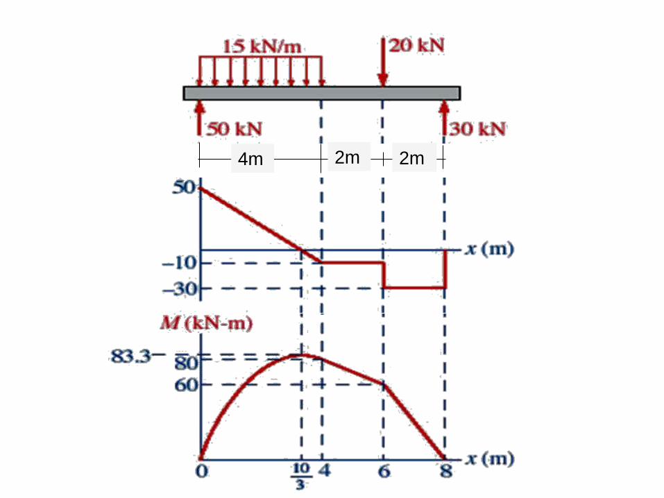
4m 2m 2m
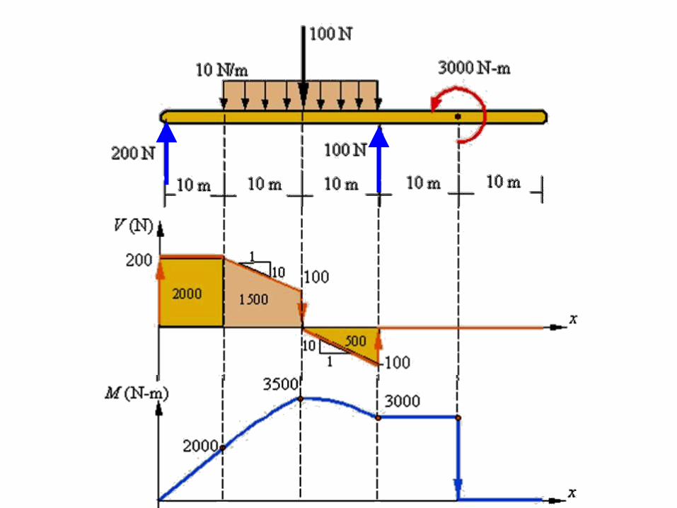
Draw shear and moment Diagrams
1.167 32.167
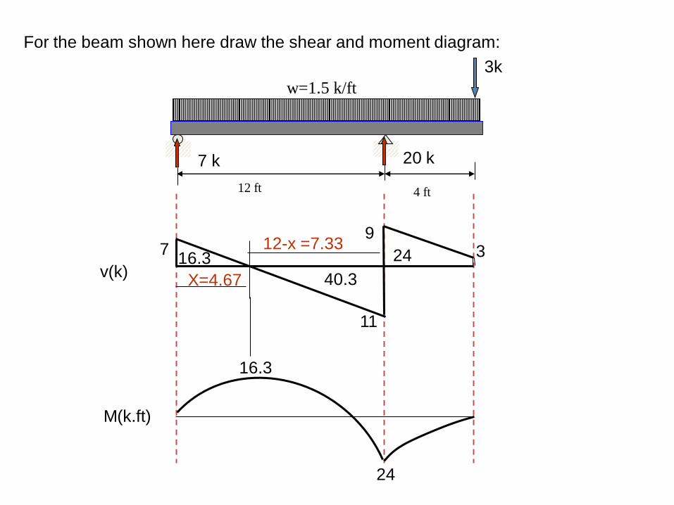
For the beam shown here draw the shear and moment diagram:
24
w=1.5 k/ft
3k
12 ft 4 ft
7 k 20 k
7
11
9 3
X=4.67
12-x =7.33
16.3
40.3
24 16.3
M(k.ft)
v(k)
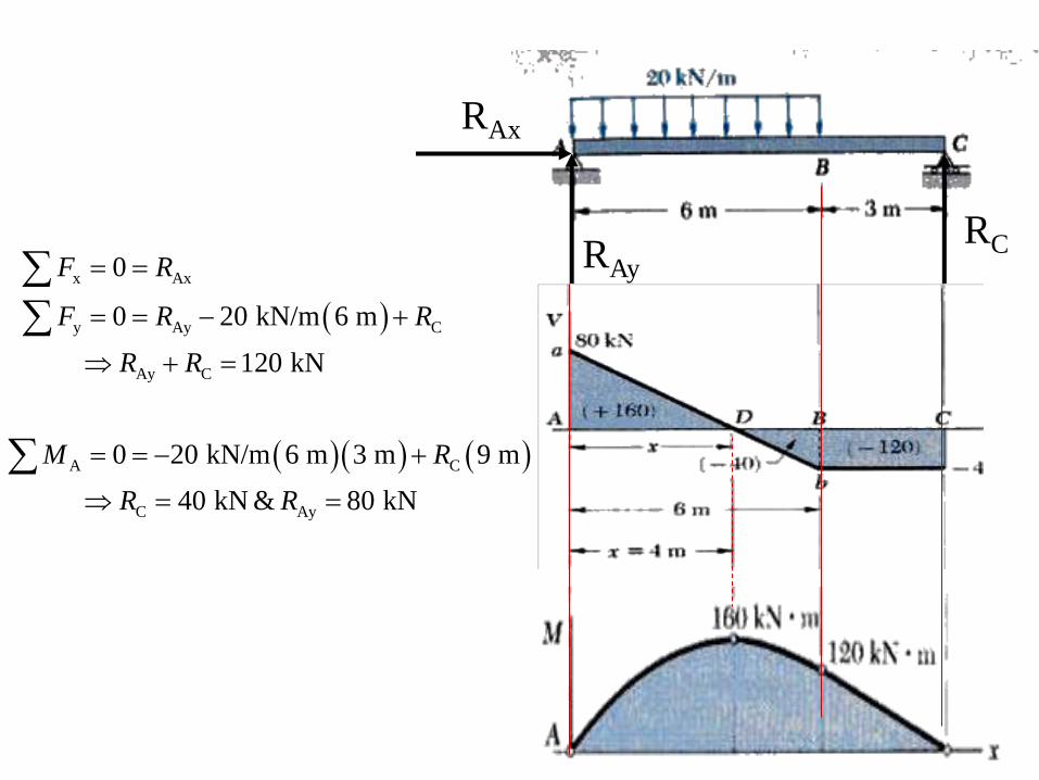
RAx
RAy RC
x Ax
y Ay C
Ay C
A C
C Ay
0
0 20 kN/m 6 m
120 kN
0 20 kN/m 6 m 3 m 9 m
40 kN & 80 kN
F R
F R R
R R
M R
R R