Embed Size (px)
Citation preview
2
Static Virtual LANs (VLANs)
Contents
Overview . . . . . . . . . . . . . . . . . . . . . . . . . . . . . . . . . . . . . . . . . . . . . . . . . . . . . . 2-2
Port-Based Virtual LANs (Static VLANs) . . . . . . . . . . . . . . . . . . . . . . . . . . . . 2-3
Overview of Using VLANs . . . . . . . . . . . . . . . . . . . . . . . . . . . . . . . . . . . . 2-6VLAN Support and the Default VLAN . . . . . . . . . . . . . . . . . . . . . . . 2-6The Primary VLAN . . . . . . . . . . . . . . . . . . . . . . . . . . . . . . . . . . . . . . . 2-6Per-Port Static VLAN Configuration Options . . . . . . . . . . . . . . . . . 2-8General Steps for Using VLANs . . . . . . . . . . . . . . . . . . . . . . . . . . . . 2-9VLAN Operating Notes . . . . . . . . . . . . . . . . . . . . . . . . . . . . . . . . . . . 2-9
Multiple VLAN Considerations . . . . . . . . . . . . . . . . . . . . . . . . . . . . . . . . 2-9Single-Forwarding Database Operation . . . . . . . . . . . . . . . . . . . . 2-11Example of an Unsupported Configuration and How to Correct It . . . . . . . . . . . . . . . . . . . . . . . . . . . . . . . . . . . . . . . 2-11Multiple-Forwarding Database Operation . . . . . . . . . . . . . . . . . . 2-13
Menu: Configuring VLAN Parameters . . . . . . . . . . . . . . . . . . . . . . . . . . 2-14To Change VLAN Support Settings . . . . . . . . . . . . . . . . . . . . . . . . 2-14Adding or Editing VLAN Names . . . . . . . . . . . . . . . . . . . . . . . . . . . 2-16Adding or Changing a VLAN Port Assignment . . . . . . . . . . . . . . . 2-17
CLI: Configuring VLAN Parameters . . . . . . . . . . . . . . . . . . . . . . . . . . . 2-19
Web: Viewing and Configuring VLAN Parameters . . . . . . . . . . . . . . . 2-25
802.1Q VLAN Tagging . . . . . . . . . . . . . . . . . . . . . . . . . . . . . . . . . . . . . . . 2-26
The Secure Management VLAN . . . . . . . . . . . . . . . . . . . . . . . . . . . . . . . 2-30Preparation . . . . . . . . . . . . . . . . . . . . . . . . . . . . . . . . . . . . . . . . . . . . 2-32Configuration . . . . . . . . . . . . . . . . . . . . . . . . . . . . . . . . . . . . . . . . . . 2-33Operating Notes for Management VLANs . . . . . . . . . . . . . . . . . . . 2-33
Effect of VLANs on Other Switch Features . . . . . . . . . . . . . . . . . . . . . 2-34Spanning Tree Operation with VLANs . . . . . . . . . . . . . . . . . . . . . 2-34IP Interfaces . . . . . . . . . . . . . . . . . . . . . . . . . . . . . . . . . . . . . . . . . . . 2-35VLAN MAC Addresses . . . . . . . . . . . . . . . . . . . . . . . . . . . . . . . . . . . 2-35Port Trunks . . . . . . . . . . . . . . . . . . . . . . . . . . . . . . . . . . . . . . . . . . . . 2-35Port Monitoring . . . . . . . . . . . . . . . . . . . . . . . . . . . . . . . . . . . . . . . . 2-36
VLAN Restrictions . . . . . . . . . . . . . . . . . . . . . . . . . . . . . . . . . . . . . . . . . . 2-36
Jumbo Packet Support on the Series 2800 Switches . . . . . . . . . . . . . 2-36
2-1
Static Virtual LANs (VLANs) Overview
Overview
This chapter describes how to configure and use static, port-based VLANs on the switches covered by this manual.
For general information on how to use the switch’s built-in interfaces, refer to these chapters in the Management and Configuration Guide for your switch:
■ Chapter 3, “Using the Menu Interface”
■ Chapter 4, “Using the Command Line Interface (CLI)”
■ Chapter 5, “Using the Web Browser Interface”
■ Chapter 6, “Switch Memory and Configuration”
2-2
Static Virtual LANs (VLANs)Port-Based Virtual LANs (Static VLANs)
Port-Based Virtual LANs (Static VLANs)
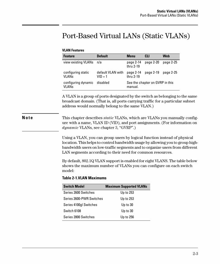
VLAN Features
A VLAN is a group of ports designated by the switch as belonging to the same broadcast domain. (That is, all ports carrying traffic for a particular subnet address would normally belong to the same VLAN.)
N o t e This chapter describes static VLANs, which are VLANs you manually config-ure with a name, VLAN ID (VID), and port assignments. (For information on dynamic VLANs, see chapter 3, “GVRP”.)
Using a VLAN, you can group users by logical function instead of physical location. This helps to control bandwidth usage by allowing you to group high-bandwidth users on low-traffic segments and to organize users from different LAN segments according to their need for common resources.
By default, 802.1Q VLAN support is enabled for eight VLANS. The table below shows the maximum number of VLANs you can configure on each switch model:
Table 2-1.VLAN Maximums
Feature Default Menu CLI Web
view existing VLANs n/a page 2-14 thru 2-19
page 2-20 page 2-25
configuring static VLANs
default VLAN with VID = 1
page 2-14 thru 2-19
page 2-19 page 2-25
configuring dynamic VLANs
disabled See the chapter on GVRP in this manual.
Switch Model Maximum Supported VLANs
Series 2600 Switches Up to 253
Series 2600-PWR Switches Up to 253
Series 4100gl Switches Up to 30
Switch 6108 Up to 30
Series 2800 Switches Up to 256
2-3
Static Virtual LANs (VLANs) Port-Based Virtual LANs (Static VLANs)
(802.1Q compatibility enables you to assign each switch port to multiple VLANs, if needed, and the port-based nature of the configuration allows interoperation with older switches that require a separate port for each VLAN.)
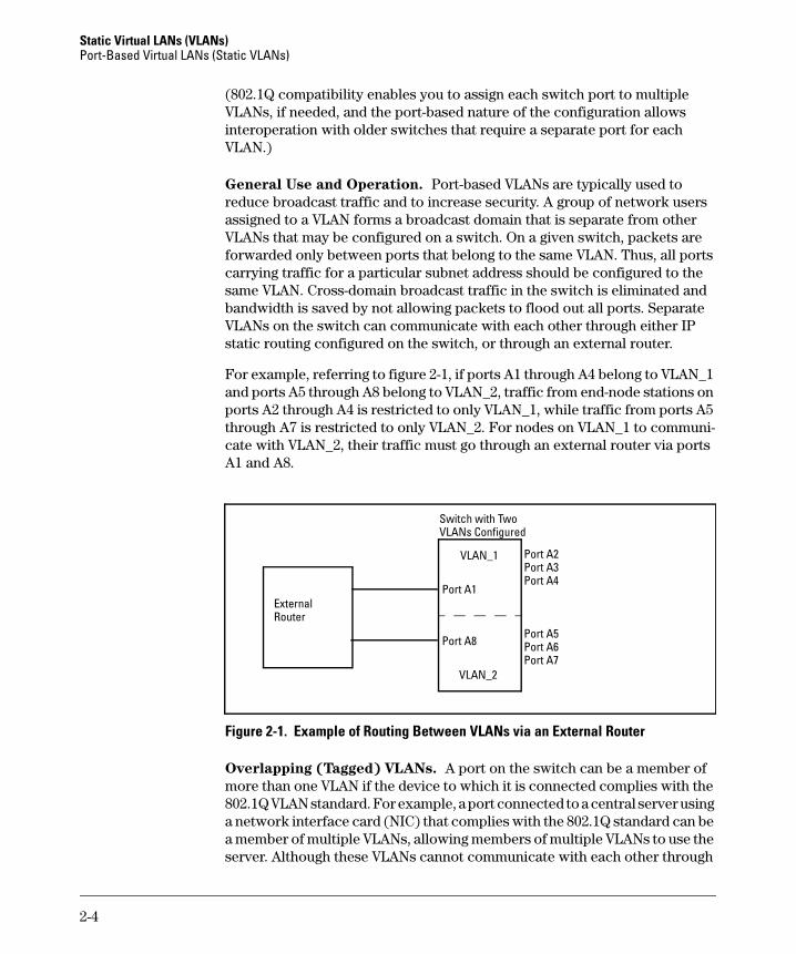
General Use and Operation. Port-based VLANs are typically used to reduce broadcast traffic and to increase security. A group of network users assigned to a VLAN forms a broadcast domain that is separate from other VLANs that may be configured on a switch. On a given switch, packets are forwarded only between ports that belong to the same VLAN. Thus, all ports carrying traffic for a particular subnet address should be configured to the same VLAN. Cross-domain broadcast traffic in the switch is eliminated and bandwidth is saved by not allowing packets to flood out all ports. Separate VLANs on the switch can communicate with each other through either IP static routing configured on the switch, or through an external router.
For example, referring to figure 2-1, if ports A1 through A4 belong to VLAN_1 and ports A5 through A8 belong to VLAN_2, traffic from end-node stations on ports A2 through A4 is restricted to only VLAN_1, while traffic from ports A5 through A7 is restricted to only VLAN_2. For nodes on VLAN_1 to communi-cate with VLAN_2, their traffic must go through an external router via ports A1 and A8.
Figure 2-1. Example of Routing Between VLANs via an External Router
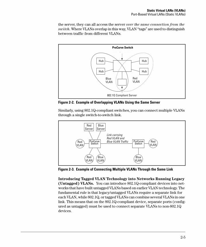
Overlapping (Tagged) VLANs. A port on the switch can be a member of more than one VLAN if the device to which it is connected complies with the 802.1Q VLAN standard. For example, a port connected to a central server using a network interface card (NIC) that complies with the 802.1Q standard can be a member of multiple VLANs, allowing members of multiple VLANs to use the server. Although these VLANs cannot communicate with each other through
ExternalRouter
VLAN_2
VLAN_1
Port A1
Port A8
Port A2Port A3Port A4
Port A5Port A6Port A7
Switch with Two VLANs Configured
2-4
Static Virtual LANs (VLANs)Port-Based Virtual LANs (Static VLANs)
the server, they can all access the server over the same connection from the
switch. Where VLANs overlap in this way, VLAN “tags” are used to distinguish between traffic from different VLANs.
Figure 2-2. Example of Overlapping VLANs Using the Same Server
Similarly, using 802.1Q-compliant switches, you can connect multiple VLANs through a single switch-to-switch link.
Figure 2-3. Example of Connecting Multiple VLANs Through the Same Link
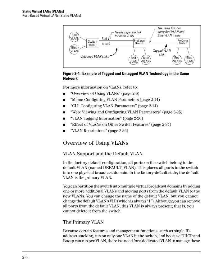
Introducing Tagged VLAN Technology into Networks Running Legacy
(Untagged) VLANs. You can introduce 802.1Q-compliant devices into net-works that have built untagged VLANs based on earlier VLAN technology. The fundamental rule is that legacy/untagged VLANs require a separate link for each VLAN, while 802.1Q, or tagged VLANs can combine several VLANs in one link. This means that on the 802.1Q-compliant device, separate ports (config-ured as untagged) must be used to connect separate VLANs to non-802.1Q devices.
ProCurve Switch
ProCurve Switch
ProCurve Switch
2-5
Static Virtual LANs (VLANs) Port-Based Virtual LANs (Static VLANs)
Figure 2-4. Example of Tagged and Untagged VLAN Technology in the Same Network
For more information on VLANs, refer to:
■ “Overview of Using VLANs” (page 2-6)
■ “Menu: Configuring VLAN Parameters (page 2-14)
■ “CLI: Configuring VLAN Parameters” (page 2-14)
■ “Web: Viewing and Configuring VLAN Parameters” (page 2-25)
■ “VLAN Tagging Information” (page 2-26)
■ “Effect of VLANs on Other Switch Features” (page 2-34)
■ “VLAN Restrictions” (page 2-36)
Overview of Using VLANs
VLAN Support and the Default VLAN
In the factory default configuration, all ports on the switch belong to the default VLAN (named DEFAULT_VLAN). This places all ports in the switch into one physical broadcast domain. In the factory-default state, the default VLAN is the primary VLAN.
You can partition the switch into multiple virtual broadcast domains by adding one or more additional VLANs and moving ports from the default VLAN to the new VLANs. You can change the name of the default VLAN, but you cannot change the default VLAN’s VID (which is always “1”). Although you can remove all ports from the default VLAN, this VLAN is always present; that is, you cannot delete it from the switch.
The Primary VLAN
Because certain features and management functions, such as single IP-address stacking, run on only one VLAN in the switch, and because DHCP and Bootp can run per-VLAN, there is a need for a dedicated VLAN to manage these
Non-802.1Q-compliant switch
Switch
Switch2524
ProCurve Switch
ProCurve Switch
Untagged VLAN Links
Tagged VLANLink
2-6
Static Virtual LANs (VLANs)Port-Based Virtual LANs (Static VLANs)
features and ensure that multiple instances of DHCP or Bootp on different VLANs do not result in conflicting configuration values for the switch. The primary VLAN is the VLAN the switch uses to run and manage these features and data. In the factory-default configuration, the switch designates the default VLAN (DEFAULT_VLAN) as the primary VLAN. However, to provide more control in your network, you can designate another VLAN as primary. To summarize, designating a non-default VLAN as primary means that:
■ The stacking feature runs on the switch’s designated primary VLAN instead of the default VLAN
■ The switch reads DHCP responses on the primary VLAN instead of on the default VLAN. (This includes such DHCP-resolved parameters as the TimeP server address, Default TTL, and IP addressing—including the Gateway IP address—when the switch configuration specifies DHCP as the source for these values.)
■ The default VLAN continues to operate as a standard VLAN (except, as noted above, you cannot delete it or change its VID).
■ Any ports not specifically assigned to another VLAN will remain assigned to the Default VLAN, regardless of whether it is the primary VLAN.
Candidates for primary VLAN include any static VLAN currently configured on the switch. (A dynamic—GVRP-learned—VLAN that has not been con-verted to a static VLAN cannot be the primary VLAN.) To display the current primary VLAN, use the CLI show vlan command.
N o t e If you configure a non-default VLAN as the primary VLAN, you cannot delete that VLAN unless you first select a different VLAN to act as primary.
If you manually configure a gateway on the switch, it will ignore any gateway address received via DHCP or Bootp.
2-7
Static Virtual LANs (VLANs) Port-Based Virtual LANs (Static VLANs)
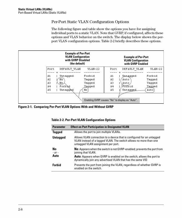
Per-Port Static VLAN Configuration Options
The following figure and table show the options you have for assigning individual ports to a static VLAN. Note that GVRP, if configured, affects these options and VLAN behavior on the switch. The display below shows the per-port VLAN configuration options. Table 2-2 briefly describes these options.
Figure 2-1. Comparing Per-Port VLAN Options With and Without GVRP
Table 2-2. Per-Port VLAN Configuration Options
Example of Per-Port VLAN Configuration with GVRP Disabled
(the default)
Example of Per-Port VLAN Configuration with GVRP Enabled
Enabling GVRP causes “No” to display as “Auto”.
Parameter Effect on Port Participation in Designated VLAN
Tagged Allows the port to join multiple VLANs.
Untagged Allows VLAN connection to a device that is configured for an untagged VLAN instead of a tagged VLAN. The switch allows no more than one untagged VLAN assignment per port.
No - or -Auto
No: Appears when the switch is not GVRP-enabled; prevents the port from joining that VLAN.Auto: Appears when GVRP is enabled on the switch; allows the port to dynamically join any advertised VLAN that has the same VID
Forbid Prevents the port from joining the VLAN, regardless of whether GVRP is enabled on the switch.
2-8
Static Virtual LANs (VLANs)Port-Based Virtual LANs (Static VLANs)
General Steps for Using VLANs
1. Plan your VLAN strategy and create a map of the logical topology that will result from configuring VLANs. Include consideration for the interaction between VLANs and other features such as Spanning Tree Protocol, load balancing, and IGMP. (Refer to “Effect of VLANs on Other Switch Fea-tures” on page 2-34.) If you plan on using dynamic VLANs, include the port configuration planning necessary to support this feature. (See chapter 3, “GVRP”. )
By default, VLAN support is enabled and the switch is configured for eight VLANs.
2. Configure at least one VLAN in addition to the default VLAN.
3. Assign the desired switch ports to the new VLAN(s).
4. If you are managing VLANs with SNMP in an IP network, each VLAN must have an IP address. Refer to the chapter on IP addressing in the Manage-
ment and Configuration Guide.
VLAN Operating Notes
■ If you are using DHCP/Bootp to acquire the switch’s configuration, packet time-to-live, and TimeP information, you must designate the VLAN on which DHCP is configured for this purpose as the primary VLAN. (In the factory-default configuration, the DEFAULT_VLAN is the primary VLAN.)
■ IGMP, and some other features operate on a “per VLAN” basis. This means you must configure such features separately for each VLAN in which you want them to operate.
■ You can rename the default VLAN, but you cannot change its VID (1) or delete it from the switch.
■ Any ports not specifically assigned to another VLAN will remain assigned to the DEFAULT_VLAN.
■ To delete a VLAN from the switch, you must first remove from that VLAN any ports assigned to it.
■ Changing the number of VLANs supported on the switch requires a reboot. Other VLAN configuration changes are dynamic.
Multiple VLAN Considerations
Switches use a forwarding database to maintain awareness of which external devices are located on which VLANs. Some switches, such as those covered by this guide, have a multiple-forwarding database, which means the switch allows multiple database entries of the same MAC address, with each entry
2-9
Static Virtual LANs (VLANs) Port-Based Virtual LANs (Static VLANs)
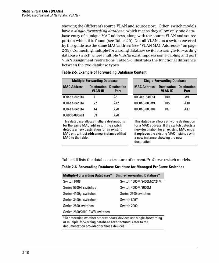
showing the (different) source VLAN and source port. Other switch models have a single-forwarding database, which means they allow only one data-base entry of a unique MAC address, along with the source VLAN and source port on which it is found (see Table 2-5). Not all VLANs on a switch covered by this guide use the same MAC address (see “VLAN MAC Addresses” on page 2-35). Connecting multiple-forwarding database switch to a single-forwarding database switch where multiple VLANs exist imposes some cabling and port VLAN assignment restrictions. Table 2-5 illustrates the functional difference between the two database types.
Table 2-5. Example of Forwarding Database Content
Table 2-6 lists the database structure of current ProCurve switch models.
Table 2-6. Forwarding Database Structure for Managed ProCurve Switches
Multiple-Forwarding Database Single-Forwarding Database
MAC Address Destination VLAN ID
Destination Port
MAC Address Destination VLAN ID
Destination Port
0004ea-84d9f4 1 A5 0004ea-84d9f4 100 A9
0004ea-84d9f4 22 A12 0060b0-880af9 105 A10
0004ea-84d9f4 44 A20 0060b0-880a81 107 A17
0060b0-880a81 33 A20
This database allows multiple destinations for the same MAC address. If the switch detects a new destination for an existing MAC entry, it just adds a new instance of that MAC to the table.
This database allows only one destination for a MAC address. If the switch detects a new destination for an existing MAC entry, it replaces the existing MAC instance with a new instance showing the new destination.
Multiple-Forwarding Databases* Single-Forwarding Database*
Switch 6108 Switch 1600M/2400M/2424M
Series 5300xl switches Switch 4000M/8000M
Series 4100gl switches Series 2500 switches
Series 3400cl switches Switch 800T
Series 2800 switches Switch 2000
Series 2600/2600-PWR switches
*To determine whether other vendors’ devices use single-forwarding or multiple-forwarding database architectures, refer to the documentation provided for those devices.
2-10
Static Virtual LANs (VLANs)Port-Based Virtual LANs (Static VLANs)
Single-Forwarding Database Operation
When a packet arrives with a destination MAC address that matches a MAC address in the switch’s forwarding table, the switch tries to send the packet to the port listed for that MAC address. But, if the destination port is in a different VLAN than the VLAN on which the packet was received, the switch drops the packet. This is not a problem for a switch with a multiple-forwarding database (refer to table 2-6, above) because the switch allows multiple instances of a given MAC address; one for each valid destination. However, a switch with a single-forwarding database allows only one instance of a given MAC address. If (1) you connect the two types of switches through multiple ports or trunks belonging to different VLANs, and (2) enable routing on the switch having the multiple-forwarding database; then, on the switch having the single-forwarding database, the port and VLAN record it maintains for the connected multiple-forwarding-database switch can frequently change. This causes poor performance and the appearance of an intermittent or broken connection.
Example of an Unsupported Configuration and How to Correct It
The Problem. In figure 2-2, the MAC address table for Switch 8000M will sometimes record the multiple-forwarding database switch as accessed on port A1 (VLAN 1), and other times as accessed on port B1 (VLAN 2):
Figure 2-2. Example of Invalid Configuration for Single-Forwarding to Multiple-Forwarding Database Devices in a Multiple VLAN Environment
In figure 2-2, PC “A” sends an IP packet to PC “B”.
Switch 8000M
VLAN 1 VLAN 2
Multiple-Forwarding Database SwitchRouting Enabled
(Same MAC address for all VLANs.)
VLAN 1 VLAN 2
This switch has multiple forwarding databases.
This switch has a single forwarding database.
PC “A” PC “B”A1 B1
C1 D1
2-11
Static Virtual LANs (VLANs) Port-Based Virtual LANs (Static VLANs)
1. The packet enters VLAN 1 in the Switch 8000 with the multiple-forwarding database switch MAC address in the destination field. Because the 8000M has not yet learned this MAC address, it does not find the address in its address table, and floods the packet out all ports, including the VLAN 1 link (port “A1”) to the multiple-forwarding database switch. The multiple-forwarding database switch then routes the packet through the VLAN 2 link to the 8000M, which forwards the packet on to PC “B”. Because the 8000M received the packet from the multiple-forwarding database switch on VLAN 2 (port “B1”), the 8000M’s single forwarding database records the multiple-forwarding database switch as being on port “B1” (VLAN 2).
2. PC “A” now sends a second packet to PC “B”. The packet again enters VLAN 1 in the Switch 8000 with the multiple-forwarding database switch’s MAC address in the destination field. However, this time the Switch 8000M’s single forwarding database indicates that the multiple-forward-ing database switch is on port B1 (VLAN 2), and the 8000M drops the packet instead of forwarding it.
3. Later, the multiple-forwarding database switch transmits a packet to the 8000M through the VLAN 1 link, and the 8000M updates its address table to indicate that the multiple-forwarding database switch is on port A1 (VLAN 1) instead of port B1 (VLAN 2). Thus, the 8000M’s information on the location of the multiple-forwarding database switch changes over time. For this reason, the 8000M discards some packets directed through it for the multiple-forwarding database switch, resulting in poor perfor-mance and the appearance of an intermittent or broken link.
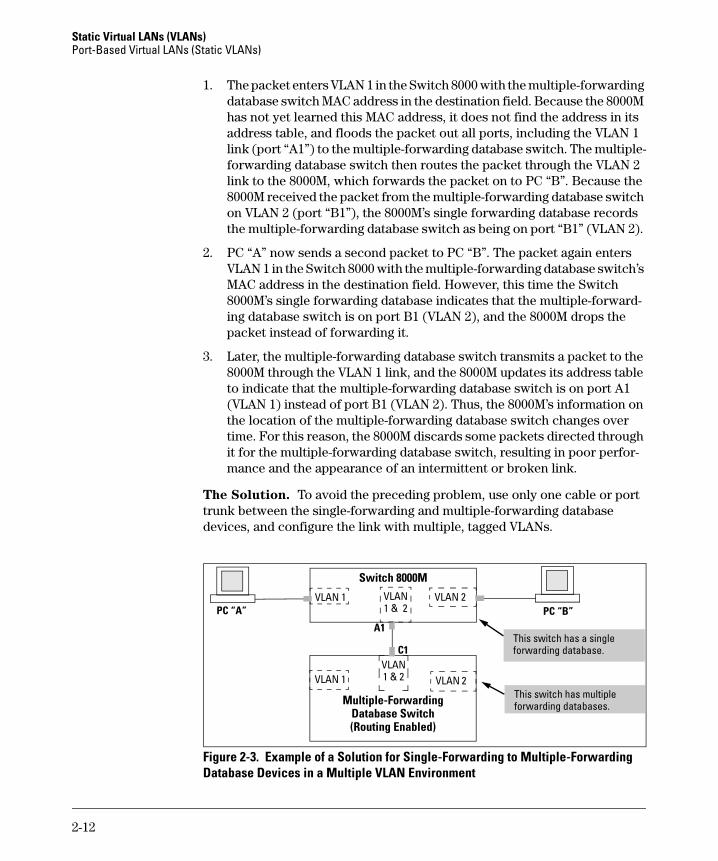
The Solution. To avoid the preceding problem, use only one cable or port trunk between the single-forwarding and multiple-forwarding database devices, and configure the link with multiple, tagged VLANs.
Figure 2-3. Example of a Solution for Single-Forwarding to Multiple-Forwarding Database Devices in a Multiple VLAN Environment
Switch 8000M
VLAN 1 VLAN 2
Multiple-Forwarding Database Switch(Routing Enabled)
VLAN 1 VLAN 2This switch has multiple forwarding databases.
This switch has a single forwarding database.
PC “A” PC “B”VLAN1 & 2
VLAN 1 & 2
A1
C1
2-12
Static Virtual LANs (VLANs)Port-Based Virtual LANs (Static VLANs)
Now, the 8000M forwarding database always lists the multiple-forwarding database switch MAC address on port A1, and the 8000M will send traffic to either VLAN on the multiple-forwarding database switch.
To increase the network bandwidth of the connection between the devices, you can use a trunk of multiple physical links rather than a single physical link.
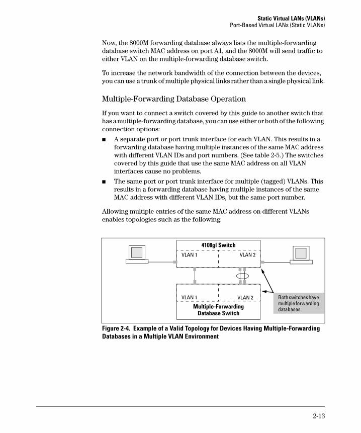
Multiple-Forwarding Database Operation
If you want to connect a switch covered by this guide to another switch that has a multiple-forwarding database, you can use either or both of the following connection options:
■ A separate port or port trunk interface for each VLAN. This results in a forwarding database having multiple instances of the same MAC address with different VLAN IDs and port numbers. (See table 2-5.) The switches covered by this guide that use the same MAC address on all VLAN interfaces cause no problems.
■ The same port or port trunk interface for multiple (tagged) VLANs. This results in a forwarding database having multiple instances of the same MAC address with different VLAN IDs, but the same port number.
Allowing multiple entries of the same MAC address on different VLANs enables topologies such as the following:
Figure 2-4. Example of a Valid Topology for Devices Having Multiple-Forwarding Databases in a Multiple VLAN Environment
4108gl Switch
VLAN 1 VLAN 2
Multiple-Forwarding Database Switch
VLAN 1
VLAN 2 Both switches have multiple forwarding databases.
2-13
Static Virtual LANs (VLANs) Port-Based Virtual LANs (Static VLANs)
Menu: Configuring VLAN Parameters
In the factory default state, support is enabled for up to eight VLANs. (You can change the switch VLAN configuration to support additional VLANs. Refer to table 2-1 on page 2-3.) Also, all ports on the switch belong to the default VLAN (DEFAULT_VLAN) and are in the same broadcast/multicast domain. (The default VLAN is also the default primary VLAN—see “The Primary VLAN” on page 2-6.) In addition to the default VLAN, you can configure up to 29 other static VLANs by changing the “Maximum VLANs” parameter, adding new VLAN names and VIDs, and then assigning one or more ports to each VLAN. Note that each port can be assigned to multiple VLANs by using VLAN tagging. (See “802.1Q VLAN Tagging” on page 2-26.)
To Change VLAN Support Settings
This section describes:
■ Changing the maximum number of VLANs to support
■ Changing the primary VLAN selection (See “Changing the Primary VLAN” on page 2-22.)
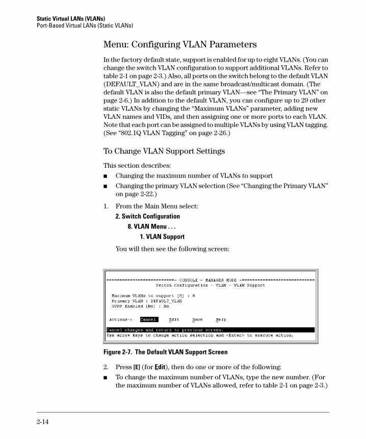
1. From the Main Menu select:
2. Switch Configuration8. VLAN Menu . . .
1. VLAN Support
You will then see the following screen:
Figure 2-7. The Default VLAN Support Screen
2. Press [E] (for Edit), then do one or more of the following:
■ To change the maximum number of VLANs, type the new number. (For the maximum number of VLANs allowed, refer to table 2-1 on page 2-3.)
2-14
Static Virtual LANs (VLANs)Port-Based Virtual LANs (Static VLANs)
■ To designate a different VLAN as the primary VLAN, select the Primary VLAN field and use the space bar to select from the existing options.
■ To enable or disable dynamic VLANs, select the GVRP Enabled field and use the Space bar to toggle between options. (For GVRP information, see chapter 3, “GVRP”.)
N o t e For optimal switch memory utilization, set the number of VLANs at the number you will likely be using or a few more. If you need more VLANs later, you can increase this number, but a switch reboot will be required at that time.
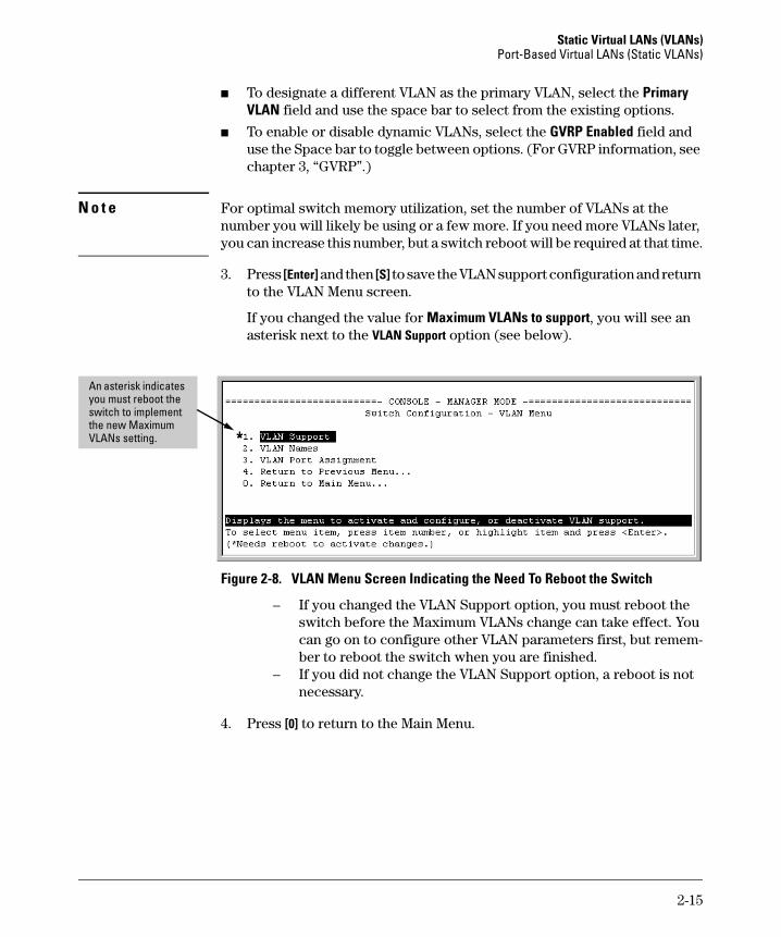
3. Press [Enter] and then [S] to save the VLAN support configuration and return to the VLAN Menu screen.
If you changed the value for Maximum VLANs to support, you will see an asterisk next to the VLAN Support option (see below).
Figure 2-8. VLAN Menu Screen Indicating the Need To Reboot the Switch
– If you changed the VLAN Support option, you must reboot the switch before the Maximum VLANs change can take effect. You can go on to configure other VLAN parameters first, but remem-ber to reboot the switch when you are finished.
– If you did not change the VLAN Support option, a reboot is not necessary.
4. Press [0] to return to the Main Menu.
An asterisk indicates you must reboot the switch to implement the new Maximum VLANs setting.
2-15
Static Virtual LANs (VLANs) Port-Based Virtual LANs (Static VLANs)
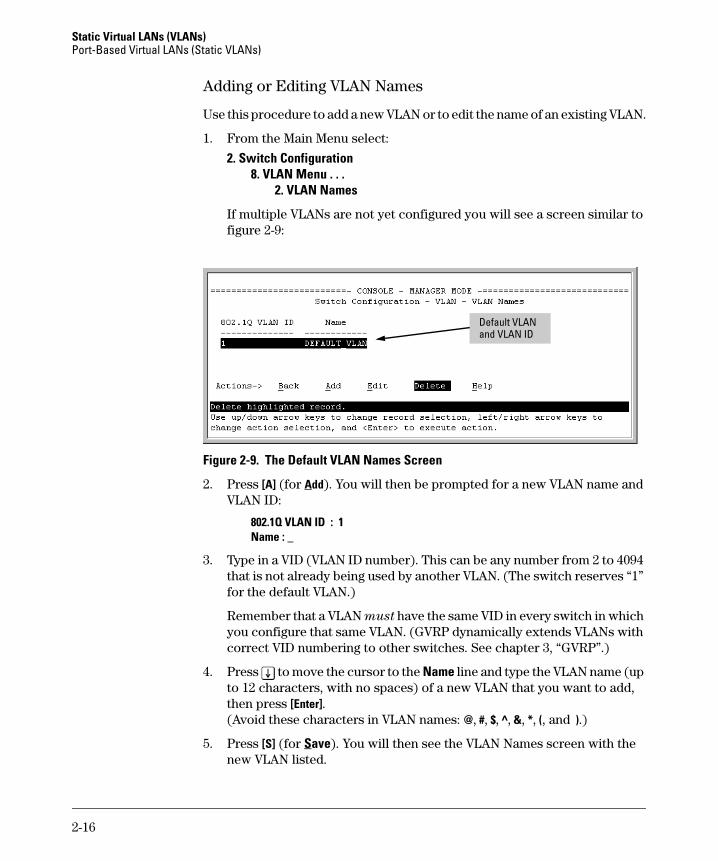
Adding or Editing VLAN Names
Use this procedure to add a new VLAN or to edit the name of an existing VLAN.
1. From the Main Menu select:
2. Switch Configuration8. VLAN Menu . . .
2. VLAN Names
If multiple VLANs are not yet configured you will see a screen similar to figure 2-9:
Figure 2-9. The Default VLAN Names Screen
2. Press [A] (for Add). You will then be prompted for a new VLAN name and VLAN ID:
802.1Q VLAN ID : 1Name : _
3. Type in a VID (VLAN ID number). This can be any number from 2 to 4094 that is not already being used by another VLAN. (The switch reserves “1” for the default VLAN.)
Remember that a VLAN must have the same VID in every switch in which you configure that same VLAN. (GVRP dynamically extends VLANs with correct VID numbering to other switches. See chapter 3, “GVRP”.)
4. Press [v] to move the cursor to the Name line and type the VLAN name (up to 12 characters, with no spaces) of a new VLAN that you want to add, then press [Enter]. (Avoid these characters in VLAN names: @, #, $, ^, &, *, (, and ).)
5. Press [S] (for Save). You will then see the VLAN Names screen with the new VLAN listed.
Default VLAN and VLAN ID
2-16
Static Virtual LANs (VLANs)Port-Based Virtual LANs (Static VLANs)
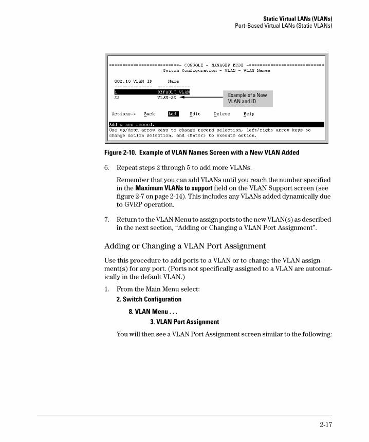
Figure 2-10. Example of VLAN Names Screen with a New VLAN Added
6. Repeat steps 2 through 5 to add more VLANs.
Remember that you can add VLANs until you reach the number specified in the Maximum VLANs to support field on the VLAN Support screen (see figure 2-7 on page 2-14). This includes any VLANs added dynamically due to GVRP operation.
7. Return to the VLAN Menu to assign ports to the new VLAN(s) as described in the next section, “Adding or Changing a VLAN Port Assignment”.
Adding or Changing a VLAN Port Assignment
Use this procedure to add ports to a VLAN or to change the VLAN assign-ment(s) for any port. (Ports not specifically assigned to a VLAN are automat-ically in the default VLAN.)
1. From the Main Menu select:
2. Switch Configuration
8. VLAN Menu . . . 3. VLAN Port Assignment
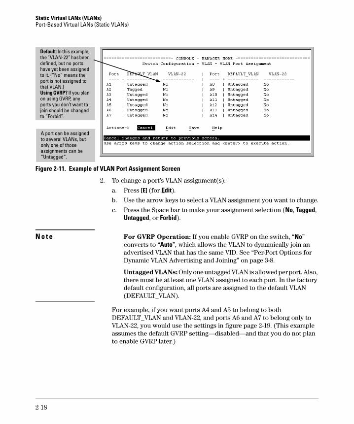
You will then see a VLAN Port Assignment screen similar to the following:
Example of a New VLAN and ID
2-17
Static Virtual LANs (VLANs) Port-Based Virtual LANs (Static VLANs)
Figure 2-11. Example of VLAN Port Assignment Screen
2. To change a port’s VLAN assignment(s):
a. Press [E] (for Edit).
b. Use the arrow keys to select a VLAN assignment you want to change.
c. Press the Space bar to make your assignment selection (No, Tagged, Untagged, or Forbid).
N o t e For GVRP Operation: If you enable GVRP on the switch, “No” converts to “Auto”, which allows the VLAN to dynamically join an advertised VLAN that has the same VID. See “Per-Port Options for Dynamic VLAN Advertising and Joining” on page 3-8.
Untagged VLANs: Only one untagged VLAN is allowed per port. Also, there must be at least one VLAN assigned to each port. In the factory default configuration, all ports are assigned to the default VLAN (DEFAULT_VLAN).
For example, if you want ports A4 and A5 to belong to both DEFAULT_VLAN and VLAN-22, and ports A6 and A7 to belong only to VLAN-22, you would use the settings in figure page 2-19. (This example assumes the default GVRP setting—disabled—and that you do not plan to enable GVRP later.)
Default: In this example, the “VLAN-22” has been defined, but no ports have yet been assigned to it. (“No” means the port is not assigned to that VLAN.)Using GVRP? If you plan on using GVRP, any ports you don’t want to join should be changed to “Forbid”.
A port can be assigned to several VLANs, but only one of those assignments can be “Untagged”.
2-18
Static Virtual LANs (VLANs)Port-Based Virtual LANs (Static VLANs)
Figure 2-12. Example of VLAN Assignments for Specific Ports
For information on VLAN tags (“Untagged” and “Tagged”), refer to “802.1Q VLAN Tagging” on page 2-26.
d. If you are finished assigning ports to VLANs, press [Enter] and then [S] (for Save) to activate the changes you've made and to return to the Configuration menu. (The console then returns to the VLAN menu.)
3. Return to the Main menu.
CLI: Configuring VLAN Parameters
In the factory default state, all ports on the switch belong to the default VLAN (DEFAULT_VLAN) and are in the same broadcast/multicast domain. (The default VLAN is also the default primary VLAN—see “The Primary VLAN” on page 2-6.) You can configure additional static VLANs by adding new VLAN names, and then assigning one or more ports to each VLAN. (For the maximum number of VLANs, refer to table 2-1 on page 2-3.) Note that each port can be assigned to multiple VLANs by using VLAN tagging. (See “802.1Q VLAN Tagging” on page 2-26.)
Ports A4 and A5 are assigned to both VLANs.
Ports A6 and A7 are assigned only to VLAN-22.
All other ports are assigned only to the Default VLAN.
2-19
Static Virtual LANs (VLANs) Port-Based Virtual LANs (Static VLANs)
VLAN Commands Used in this Section
Displaying the Switch’s VLAN Configuration. The next command lists the VLANs currently running in the switch, with VID, VLAN name, and VLAN status. Dynamic VLANs appear only if the switch is running with GVRP enabled and one or more ports has dynamically joined an advertised VLAN. (In the default configuration, GVRP is disabled. (See chapter 3, “GVRP”.)
Syntax: show vlan
Figure 2-13. Example of “Show VLAN” Listing (GVRP Enabled)
show vlans below
show vlan <vlan-id> page 2-21
max-vlans page 2-22
primary-vlan <vlan-id> page 2-22
[no] vlan <vlan-id> page 2-23
name <vlan-name> page 2-24
[no] tagged <port-list> page 2-24
[no] untagged <port-list> page 2-24
[no] forbid page 2-24
auto <port-list> page 2-24 (Available if GVRP enabled.)
static-vlan <vlan-id> page 2-23 (Available if GVRP enabled.)
When GVRP is disabled (the default), Dynamic VLANs do not exist on the switch and do not appear in this listing. (See chapter 3, “GVRP”.)
2-20
Static Virtual LANs (VLANs)Port-Based Virtual LANs (Static VLANs)
Displaying the Configuration for a Particular VLAN. This command uses the VID to identify and display the data for a specific static or dynamic VLAN.
Syntax: show vlan <vlan-id>
Figure 2-14. Example of “Show VLAN” for a Specific Static VLAN
Figure 2-15. Example of “Show VLAN” for a Specific Dynamic VLAN
Show VLAN lists this data when GVRP is enabled and at least one port on the switch has dynamically joined the designated VLAN.
2-21
Static Virtual LANs (VLANs) Port-Based Virtual LANs (Static VLANs)
Changing the Number of VLANs Allowed on the Switch. By default, the switch allows a maximum of 8 VLANs. You can specify any value from 1 to the upper limit for the switch. (Refer to table 2-1 on page 2-3.) If GVRP is enabled, this setting includes any dynamic VLANs on the switch. As part of implementing a new value, you must execute a write memory command (to save the new value to the startup-config file) and then reboot the switch.
Syntax: max-vlans < 1 .. 30 > (Series 4100 and Switch 6108)
< 1 .. 253 > (Series 2600, 2600 PWR)
< 1 .. 256 > (Series 2800)
For example, to reconfigure the switch to allow 10 VLANs:
Figure 2-16. Example of Command Sequence for Changing the Number of VLANs
Changing the Primary VLAN. In the factory-default configuration, the default VLAN (DEFAULT_VLAN) is the primary VLAN. However, you can designate any static VLAN on the switch as the primary VLAN. (For more on the primary VLAN, see “The Primary VLAN” on page 2-6.) To view the available VLANs and their respective VIDs, use show vlan.
Syntax: primary-vlan <vlan-id>
For example, to make VLAN 22 the primary VLAN:
ProCurve(config)# primary-vlan 22
Note that you can execute these three steps at another time.
2-22
Static Virtual LANs (VLANs)Port-Based Virtual LANs (Static VLANs)
Creating a New Static VLAN
Changing the VLAN Context Level.
With this command, entering a new VID creates a new static VLAN. Entering the VID or name of an existing static VLAN places you in the context level for that VLAN.
Syntax: vlan <vlan-id> [name <name-str>]Creates a new static VLAN if a VLAN with that VID does not
already exist, and places you in that VLAN’s context level. If
you do not use the name option, the switch uses “VLAN” and
the new VID to automatically name the VLAN. If the VLAN
already exists, the switch places you in the context level for
that VLAN.
vlan <vlan-name>Places you in the context level for that static VLAN.
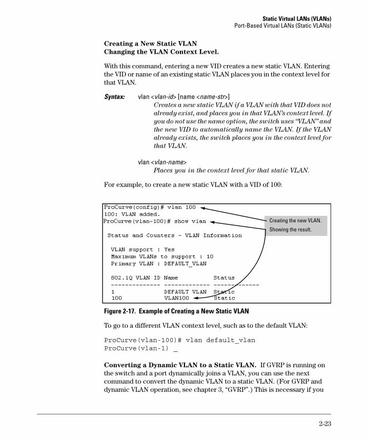
For example, to create a new static VLAN with a VID of 100:
Figure 2-17. Example of Creating a New Static VLAN
To go to a different VLAN context level, such as to the default VLAN:
ProCurve(vlan-100)# vlan default_vlanProCurve(vlan-1) _
Converting a Dynamic VLAN to a Static VLAN. If GVRP is running on the switch and a port dynamically joins a VLAN, you can use the next command to convert the dynamic VLAN to a static VLAN. (For GVRP and dynamic VLAN operation, see chapter 3, “GVRP”.) This is necessary if you
Creating the new VLAN.
Showing the result.
2-23
Static Virtual LANs (VLANs) Port-Based Virtual LANs (Static VLANs)
want to make the VLAN permanent. After you convert a dynamic VLAN to static, you must configure the switch’s per-port participation in the VLAN in the same way that you would for any static VLAN.
Syntax: static-vlan <vlan-id> (Use show vlan to list current VIDs.)
For example, suppose a dynamic VLAN with a VID of 125 exists on the switch. The following command converts the VLAN to a static VLAN.
ProCurve(config)# static-vlan 125
Configuring Static VLAN Name and Per-Port Settings. The vlan <vlan-id> command, used with the options listed below, changes the name of an existing static VLAN and changes the per-port VLAN membership settings.
N o t e You can use these options from the configuration level by beginning the command with vlan <vlan-id>, or from the context level of the specific VLAN.
Syntax: name <vlan-name>Changes the name of the existing static VLAN. (Avoid
spaces and the following characters in the <vlan-name>entry: 2, #, $, ^, &, *, (, and ).)
[no] tagged <port-list>Configures the indicated port(s) as Tagged for the specified
VLAN. The “no” version sets the port(s) to either No or (if
GVRP is enabled) to Auto.
[no] untagged <port-list>Configures the indicated port(s) as Untagged for the
specified VLAN. The “no” version sets the port(s) to either
No or (if GVRP is enabled) to Auto.
[no] forbid <port-list>Configures the indicated port(s) as “forbidden” to
participate in the designated VLAN. The “no” version sets
the port(s) to either No or (if GVRP is enabled) to Auto.
auto <port-list>Available if GVRP is enabled on the switch. Returns the
per-port settings for the specified VLAN to Auto operation.
Note that Auto is the default per-port setting for a static
VLAN if GVRP is running on the switch. (For information
on dynamic VLAN and GVRP operation, see
chapter 3, “GVRP”.)
2-24
Static Virtual LANs (VLANs)Port-Based Virtual LANs (Static VLANs)
For example, if you have a VLAN named VLAN100 with a VID of 100, and all ports are set to No for this VLAN. To change the VLAN name to “Blue_Team” and set ports 1-5 to Tagged, you could do so with these commands:
ProCurve(config)# vlan 100 name Blue_TeamProCurve(config)# vlan 100 tagged 1-5
To move to the vlan 100 context level and execute the same commands:
ProCurve(config)# vlan 100ProCurve(vlan-100)# name Blue_TeamProCurve(vlan-100)# tagged 1-5
Similarly, to change the tagged ports in the above examples to No (or Auto, if GVRP is enabled), you could use either of the following commands.
At the config level, use:ProCurve(config)# no vlan 100 tagged 1-5
- or -
At the VLAN 100 context level, use:ProCurve(vlan-100)# no tagged 1-5
N o t e You cannot use these commands with dynamic VLANs. Attempting to do so results in the message “VLAN already exists.” and no change occurs.
Web: Viewing and Configuring VLAN Parameters
In the web browser interface you can do the following:
■ Add VLANs
■ Rename VLANs
■ Remove VLANs
■ Configure GVRP mode
■ Select a new Primary VLAN
To configure static VLAN port parameters, you will need to use the menu interface (available by Telnet from the web browser interface) or the CLI.
1. Click on the Configuration tab.
2. Click on VLAN Configuration.
3. Click on Add/Remove VLANs.
For web-based Help on how to use the web browser interface screen, click on the [?] button provided on the web browser screen.
2-25
Static Virtual LANs (VLANs) Port-Based Virtual LANs (Static VLANs)
802.1Q VLAN Tagging
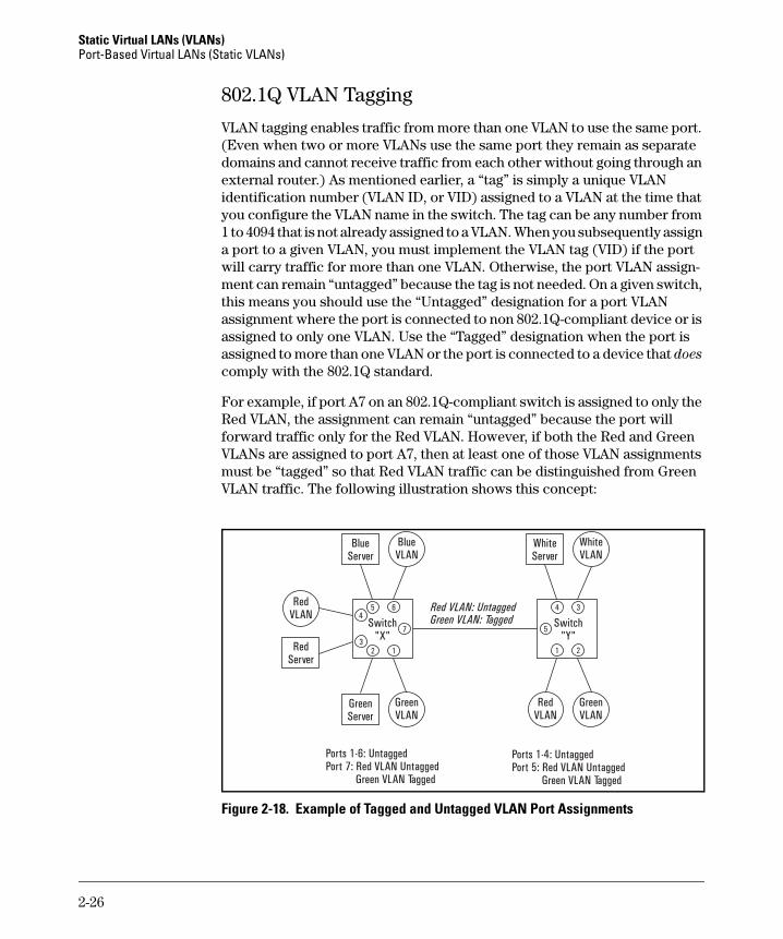
VLAN tagging enables traffic from more than one VLAN to use the same port. (Even when two or more VLANs use the same port they remain as separate domains and cannot receive traffic from each other without going through an external router.) As mentioned earlier, a “tag” is simply a unique VLAN identification number (VLAN ID, or VID) assigned to a VLAN at the time that you configure the VLAN name in the switch. The tag can be any number from 1 to 4094 that is not already assigned to a VLAN. When you subsequently assign a port to a given VLAN, you must implement the VLAN tag (VID) if the port will carry traffic for more than one VLAN. Otherwise, the port VLAN assign-ment can remain “untagged” because the tag is not needed. On a given switch, this means you should use the “Untagged” designation for a port VLAN assignment where the port is connected to non 802.1Q-compliant device or is assigned to only one VLAN. Use the “Tagged” designation when the port is assigned to more than one VLAN or the port is connected to a device that does comply with the 802.1Q standard.
For example, if port A7 on an 802.1Q-compliant switch is assigned to only the Red VLAN, the assignment can remain “untagged” because the port will forward traffic only for the Red VLAN. However, if both the Red and Green VLANs are assigned to port A7, then at least one of those VLAN assignments must be “tagged” so that Red VLAN traffic can be distinguished from Green VLAN traffic. The following illustration shows this concept:
Figure 2-18. Example of Tagged and Untagged VLAN Port Assignments
BlueServer
WhiteServer
GreenServer
RedServer
RedVLAN
BlueVLAN
WhiteVLAN
GreenVLAN
GreenVLAN
RedVLAN
Switch"X"
5 6
7
4
13
2
Switch"Y"
5
4
1
3
2
Red VLAN: UntaggedGreen VLAN: Tagged
Ports 1-6: UntaggedPort 7: Red VLAN Untagged
Green VLAN Tagged
Ports 1-4: UntaggedPort 5: Red VLAN Untagged
Green VLAN Tagged
2-26
Static Virtual LANs (VLANs)Port-Based Virtual LANs (Static VLANs)
■ In switch X:
• VLANs assigned to ports X1 - X6 can all be untagged because there is only one VLAN assignment per port. Red VLAN traffic will go out only the Red ports; Green VLAN traffic will go out only the Green ports, and so on. Devices connected to these ports do not have to be 802.1Q-compliant.
• However, because both the Red VLAN and the Green VLAN are assigned to port X7, at least one of the VLANs must be tagged for this port.
■ In switch Y:
• VLANs assigned to ports Y1 - Y4 can all be untagged because there is only one VLAN assignment per port. Devices connected to these ports do not have to be 802.1Q-compliant.
• Because both the Red VLAN and the Green VLAN are assigned to port Y5, at least one of the VLANs must be tagged for this port.
■ In both switches: The ports on the link between the two switches must be configured the same. As shown in figure 2-18 (above), the Red VLAN must be untagged on port X7 and Y5 and the Green VLAN must be tagged on port X7 and Y5, or vice-versa.
N o t e Each 802.1Q-compliant VLAN must have its own unique VID number, and that VLAN must be given the same VID in every device in which it is configured. That is, if the Red VLAN has a VID of 10 in switch X, then 10 must also be used for the Red VID in switch Y.
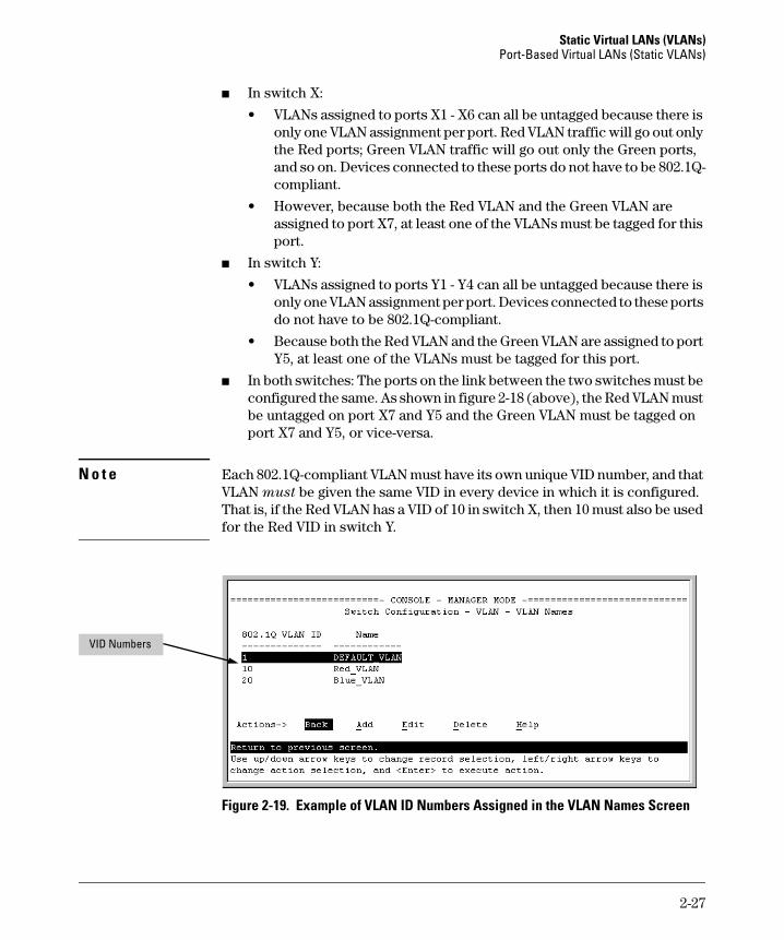
Figure 2-19. Example of VLAN ID Numbers Assigned in the VLAN Names Screen
VID Numbers
2-27
Static Virtual LANs (VLANs) Port-Based Virtual LANs (Static VLANs)
VLAN tagging gives you several options:
■ Since the purpose of VLAN tagging is to allow multiple VLANs on the same port, any port that has only one VLAN assigned to it can be configured as “Untagged” (the default).
■ Any port that has two or more VLANs assigned to it can have one VLAN assignment for that port as “Untagged”. All other VLANs assigned to the same port must be configured as “Tagged”. (There can be no more than one Untagged VLAN on a port.)
■ If all end nodes on a port comply with the 802.1Q standard and are configured to use the correct VID, then, you can configure all VLAN assignments on a port as “Tagged” if doing so makes it easier to manage your VLAN assignments, or for security reasons.
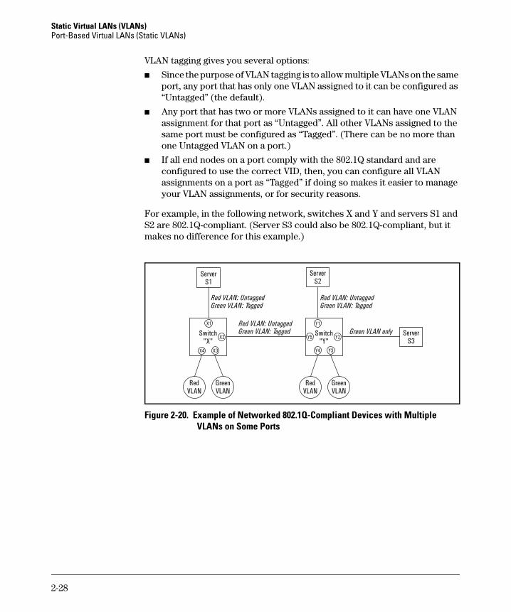
For example, in the following network, switches X and Y and servers S1 and S2 are 802.1Q-compliant. (Server S3 could also be 802.1Q-compliant, but it makes no difference for this example.)
Figure 2-20. Example of Networked 802.1Q-Compliant Devices with Multiple VLANs on Some Ports
Red VLAN: Untagged
Red VLAN: Untagged Red VLAN: Untagged
Green VLAN: Tagged
Green VLAN: Tagged Green VLAN: Tagged
Green VLAN only
ServerS1
ServerS2
ServerS3
GreenVLAN
GreenVLAN
RedVLAN
RedVLAN
Switch"X"
X1
X2
X3X4
Switch"Y"
Y1
Y4
Y2Y5
Y3
2-28
Static Virtual LANs (VLANs)Port-Based Virtual LANs (Static VLANs)
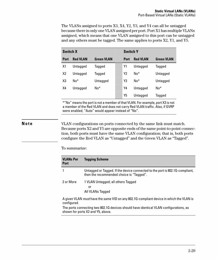
The VLANs assigned to ports X3, X4, Y2, Y3, and Y4 can all be untagged because there is only one VLAN assigned per port. Port X1 has multiple VLANs assigned, which means that one VLAN assigned to this port can be untagged and any others must be tagged. The same applies to ports X2, Y1, and Y5.
N o t e VLAN configurations on ports connected by the same link must match. Because ports X2 and Y5 are opposite ends of the same point-to-point connec-tion, both ports must have the same VLAN configuration; that is, both ports configure the Red VLAN as “Untagged” and the Green VLAN as “Tagged”.
To summarize:
Switch X Switch Y
Port Red VLAN Green VLAN Port Red VLAN Green VLAN
X1 Untagged Tagged Y1 Untagged Tagged
X2 Untagged Tagged Y2 No* Untagged
X3 No* Untagged Y3 No* Untagged
X4 Untagged No* Y4 Untagged No*
Y5 Untagged Tagged
*”No” means the port is not a member of that VLAN. For example, port X3 is not a member of the Red VLAN and does not carry Red VLAN traffic. Also, if GVRP were enabled, “Auto” would appear instead of “No”.
VLANs Per Port
Tagging Scheme
1 Untagged or Tagged. If the device connected to the port is 802.1Q-compliant, then the recommended choice is “Tagged”.
2 or More 1 VLAN Untagged; all others Tagged orAll VLANs Tagged
A given VLAN must have the same VID on any 802.1Q-compliant device in which the VLAN is configured.The ports connecting two 802.1Q devices should have identical VLAN configurations, as shown for ports X2 and Y5, above.
2-29
Static Virtual LANs (VLANs) Port-Based Virtual LANs (Static VLANs)
The Secure Management VLANConfigures a secure Management VLAN by creating an isolated network for managing the following ProCurve switches that support this feature:
Access to this VLAN, and to the switch’s management functions (Menu, CLI, and web browser interface) is available only through ports configured as members.
■ Multiple ports on the switch can belong to the Management VLAN. This allows connections for multiple management stations you want to have access to the Management VLAN, while at the same time allowing Man-agement VLAN links between switches configured for the same Manage-ment VLAN.
■ Only traffic from the Management VLAN can manage the switch, which means that only the workstations and PCs connected to ports belonging to the Management VLAN can manage and reconfigure the switch.
Figure 2-21 illustrates use of the Management VLAN feature to support man-agement access by a group of management workstations.
• Series 2600 switches
• Series 2600-PWR switches
• Series 2800 switches
• Series 3400cl switches
• Series 4100gl switches
• Series 5300xl switches
• Switch 6108
2-30
Static Virtual LANs (VLANs)Port-Based Virtual LANs (Static VLANs)
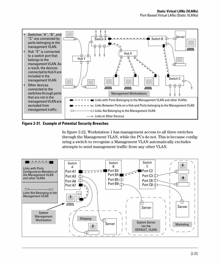
Figure 2-21. Example of Potential Security Breaches
In figure 2-22, Workstation 1 has management access to all three switches through the Management VLAN, while the PCs do not. This is because config-uring a switch to recognize a Management VLAN automatically excludes attempts to send management traffic from any other VLAN.
Links with Ports Belonging to the Management VLAN and other VLANs
Links Between Ports on a Hub and Ports belonging to the Management VLAN
Links Not Belonging to the Management VLAN
Links to Other Devices
Hub Y
Switch A
Hub X
Switch BServer
Switch C
Management Workstations
• Switches “A”, “B”, and “C” are connected by ports belonging to the management VLAN.
• Hub “X” is connected to a switch port that belongs to the management VLAN. As a result, the devices connected to Hub X are included in the management VLAN.
• Other devices connected to the switches through ports that are not in the management VLAN are excluded from management traffic.
SwitchA 3
Port A1Port A3Port A6Port A7
4
1
SwitchB
Port B2Port B4Port B5Port B9
SwitchC
Port C2Port C3Port C6Port C8
Server
Server Server
2
Links with Ports Configured as Members of the Management VLAN and other VLANs
Links Not Belonging to the Management VLAN
SystemManagement Workstation
Marketing
ShippingSystem Server
(on theDEFAULT_VLAN)
2-31
Static Virtual LANs (VLANs) Port-Based Virtual LANs (Static VLANs)
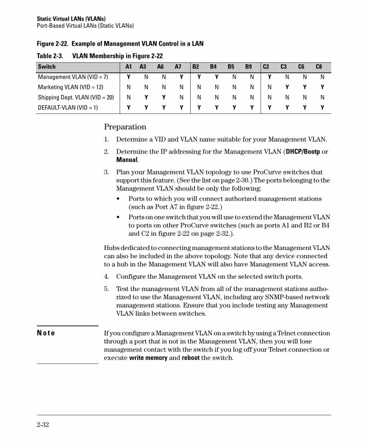
Figure 2-22. Example of Management VLAN Control in a LAN
Table 2-3. VLAN Membership in Figure 2-22
Preparation
1. Determine a VID and VLAN name suitable for your Management VLAN.
2. Determine the IP addressing for the Management VLAN (DHCP/Bootp or Manual.
3. Plan your Management VLAN topology to use ProCurve switches that support this feature. (See the list on page 2-30.) The ports belonging to the Management VLAN should be only the following:
• Ports to which you will connect authorized management stations (such as Port A7 in figure 2-22.)
• Ports on one switch that you will use to extend the Management VLAN to ports on other ProCurve switches (such as ports A1 and B2 or B4 and C2 in figure 2-22 on page 2-32.).
Hubs dedicated to connecting management stations to the Management VLAN can also be included in the above topology. Note that any device connected to a hub in the Management VLAN will also have Management VLAN access.
4. Configure the Management VLAN on the selected switch ports.
5. Test the management VLAN from all of the management stations autho-rized to use the Management VLAN, including any SNMP-based network management stations. Ensure that you include testing any Management VLAN links between switches.
N o t e If you configure a Management VLAN on a switch by using a Telnet connection through a port that is not in the Management VLAN, then you will lose management contact with the switch if you log off your Telnet connection or execute write memory and reboot the switch.
Switch A1 A3 A6 A7 B2 B4 B5 B9 C2 C3 C6 C8
Management VLAN (VID = 7) Y N N Y Y Y N N Y N N N
Marketing VLAN (VID = 12) N N N N N N N N N Y Y Y
Shipping Dept. VLAN (VID = 20) N Y Y N N N N N N N N N
DEFAULT-VLAN (VID = 1) Y Y Y Y Y Y Y Y Y Y Y Y
2-32
Static Virtual LANs (VLANs)Port-Based Virtual LANs (Static VLANs)
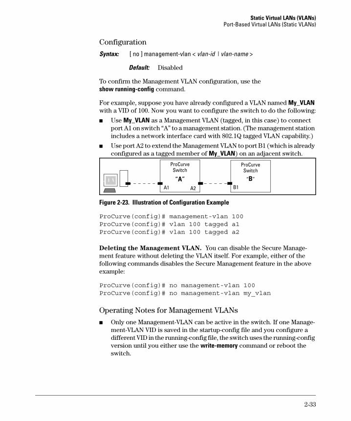
Configuration
Syntax: [ no ] management-vlan < vlan-id | vlan-name >
Default: Disabled
To confirm the Management VLAN configuration, use the show running-config command.
For example, suppose you have already configured a VLAN named My_VLAN with a VID of 100. Now you want to configure the switch to do the following:
■ Use My_VLAN as a Management VLAN (tagged, in this case) to connect port A1 on switch “A” to a management station. (The management station includes a network interface card with 802.1Q tagged VLAN capability.)
■ Use port A2 to extend the Management VLAN to port B1 (which is already configured as a tagged member of My_VLAN) on an adjacent switch.
Figure 2-23. Illustration of Configuration Example
ProCurve(config)# management-vlan 100ProCurve(config)# vlan 100 tagged a1ProCurve(config)# vlan 100 tagged a2
Deleting the Management VLAN. You can disable the Secure Manage-ment feature without deleting the VLAN itself. For example, either of the following commands disables the Secure Management feature in the above example:
ProCurve(config)# no management-vlan 100ProCurve(config)# no management-vlan my_vlan
Operating Notes for Management VLANs
■ Only one Management-VLAN can be active in the switch. If one Manage-ment-VLAN VID is saved in the startup-config file and you configure a different VID in the running-config file, the switch uses the running-config version until you either use the write-memory command or reboot the switch.
ProCurve Switch
“B”
ProCurve Switch
“A”A1 B1A2
2-33
Static Virtual LANs (VLANs) Port-Based Virtual LANs (Static VLANs)
■ During a Telnet session to the switch, if you configure the Management-VLAN to a VID that excludes the port through which you are connected to the switch, you will continue to have access only until you terminate the session by logging out or rebooting the switch.
■ During a web browser session to the switch, if you configure the Manage-ment-VLAN to a VID that excludes the port through which you are connected to the switch, you will continue to have access only until you close the browser session or rebooting the switch.
N o t e The Management-VLAN feature does not control management access through a direct connection to the switch’s serial port.
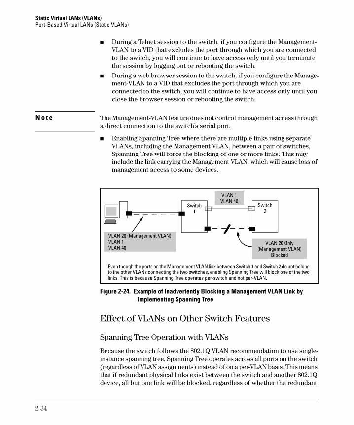
■ Enabling Spanning Tree where there are multiple links using separate VLANs, including the Management VLAN, between a pair of switches, Spanning Tree will force the blocking of one or more links. This may include the link carrying the Management VLAN, which will cause loss of management access to some devices.
Figure 2-24. Example of Inadvertently Blocking a Management VLAN Link by Implementing Spanning Tree
Effect of VLANs on Other Switch Features
Spanning Tree Operation with VLANs
Because the switch follows the 802.1Q VLAN recommendation to use single-instance spanning tree, Spanning Tree operates across all ports on the switch (regardless of VLAN assignments) instead of on a per-VLAN basis. This means that if redundant physical links exist between the switch and another 802.1Q device, all but one link will be blocked, regardless of whether the redundant
VLAN 20 (Management VLAN)VLAN 1VLAN 40
Switch1
Switch2
Even though the ports on the Management VLAN link between Switch 1 and Switch 2 do not belong to the other VLANs connecting the two switches, enabling Spanning Tree will block one of the two links. This is because Spanning Tree operates per-switch and not per-VLAN.
VLAN 1VLAN 40
VLAN 20 Only(Management VLAN)
Blocked
2-34
Static Virtual LANs (VLANs)Port-Based Virtual LANs (Static VLANs)
links are in separate VLANs. However, you can use port trunking to prevent Spanning Tree from unnecessarily blocking ports (and to improve overall network performance). Refer to “RSTP and STP Operation with 802.1Q VLANs” on page 5-9.
Note that Spanning Tree operates differently in different devices. For example, in the (obsolete, non-802.1Q) ProCurve Switch 2000 and the ProCurve Switch 800T, Spanning Tree operates on a per-VLAN basis, allowing redundant phys-ical links as long as they are in separate VLANs.
IP Interfaces
There is a one-to-one relationship between a VLAN and an IP network inter-face. Since the VLAN is defined by a group of ports, the state (up/down) of those ports determines the state of the IP network interface associated with that VLAN. When a VLAN comes up because one or more of its ports is up, the IP interface for that VLAN is also activated. Likewise, when a VLAN is deactivated because all of its ports are down, the corresponding IP interface is also deactivated.
VLAN MAC Addresses
Some switch models use the same MAC address for all configured VLANs, while other switch models use a different MAC address for each configured VLAN.
You can send an 802.2 test packet to the VLAN MAC address to verify connectivity to the switch. Likewise, you can assign an IP address to the VLAN interface, and when you Ping that address, ARP will resolve the IP address to this MAC address. (Refer to table 2-1 on page 2-3 for the maximum number of VLANs allowed on your switch).
Port Trunks
When assigning a port trunk to a VLAN, all ports in the trunk are automatically assigned to the same VLAN. You cannot split trunk members across multiple VLANs. Also, a port trunk is tagged, untagged, or excluded from a VLAN in the same way as for individual, untrunked ports.
One (Same) MAC Address for all VLANs Different MAC Address for Each VLAN
26002600-PWR
2800
3400cl5300xl6400cl
4100gl6108
2-35
Static Virtual LANs (VLANs) Port-Based Virtual LANs (Static VLANs)
Port Monitoring
If you designate a port on the switch for network monitoring, this port will appear in the Port VLAN Assignment screen and can be configured as a member of any VLAN. For information on how broadcast, multicast, and unicast packets are tagged inside and outside of the VLAN to which the monitor port is assigned, see the appendix on troubleshooting in the Manage-
ment and Configuration Guide.
VLAN Restrictions
■ A port must be a member of at least one VLAN. In the factory default configuration, all ports are assigned to the default VLAN (DEFAULT_VLAN; VID = 1).
■ A port can be assigned to several VLANs, but only one of those assign-ments can be untagged. (The “Untagged” designation enables VLAN oper-ation with non 802.1Q-compliant devices.)
■ An external router must be used to communicate between tagged VLANs on the switch.
■ Before you can delete a VLAN, you must first re-assign all ports in the VLAN to another VLAN.
Jumbo Packet Support on the Series 2800 Switches
Jumbo packet support for Series 2800 switches is enabled per-VLAN and applies to all ports belonging to the VLAN. For more information, refer to the chapter titled “Port Status and Basic Configuration” in the Management and
Configuration Guide for your switch. (Jumbo packet support is not available on the Series 2600, 2600-PWR, 4100gl or 6108 Switches.)
2-36