Embed Size (px)
Citation preview
1
STATIC LIQUEFACTION IN TAILINGS DAM AND FLOW FAILURE
Roberto Lorenzo Rodríguez Pacheco
Geological Survey of Spain - Instituto Geológico y Minero de España Departamento de Investigación en
Recursos Geológicos. Ríos Rosas, 23. 28003 Madrid, Spain
Email: [email protected]
Introduction
Mine tailings can be classified as slurry, paste, or cake, according to its final solid/liquid ratio (S:L), which
arises from the treatment given to the slurries at the end of the extraction process. Slurry undergoes no
treatment, paste is a thickened slurry, and cake is a filtered slurry (see Fig. 1).
In order to understand the phenomenon of tailings liquefaction it is necessary to answer the following
question:
What is the key to the problem of stability of tailings dam or tailings impoundment?
Tailings dams are commonly built by the discharge of slurries within an impoundment (Figs. 1, 2). They
are subjected to a number of external actions resulting from its interactions with the atmosphere, operation
and foundation (Fig. 2). Closed or operating, many physicochemical phenomena take place within or
surrounding the tailings dam, influencing directly on the dam stability. Fig. 2 embodies the typical
hydrogeological processes affecting the safety of a tailings dam.
The poured slurry usually has a solid to liquid ratio of 1:3 (v/v) (Fig. 1). Hence, the available water volume
is always relevant for the hydraulic operation of the tailings dam. Water starts to segregate from the slurry
mass at the moment it reaches the surface of the deposit. Part of the expelled water infiltrates into the
previously deposited tailings mass, while the rest flows as a surface runoff down to the decant pond. The
ratio between infiltration and runoff depends on a number of factors, such as the properties of the slurry,
the discharge rate, the discharge duration, the permeability of the deposited tailings, its degree of saturation,
the presence of retraction cracks, the position of the phreatic level (Zandarín et al., 2009).
Moreover, the deposited tailings form a beach gently sloping towards the decant pond (usually layer slop
is less than 5º). As the slurry flows along the tailings beach, a spontaneous sorting by particle size occurs.
The coarser sediments settle close to the discharge point while the finer particles move farther away. This
is a favourable effect, since it produces a material with higher hydraulic conductivity near the dam wall,
helping to depress the phreatic surface there, and hence improving the stability conditions of the deposit.
Fig. 1. a) Types of mine tailings according to its solid/liquid ratio, including profiles for gravimetric water
content, saturation degree, and water volume fraction and b) comparison between w/w and v/v ratios for a
particle density of 3 g/cm3. (modified from Garino et al., 2012 and Caparrós, 2017).

2
Fig. 2. Scheme of the factors and phenomena that affect the operation of a tailings dam (modified from
Zandarín et al., 2009).
During rainfall, additional amounts of water enter the deposit. Part of it infiltrates and the rest will flow as
surface runoff, finally reaching the decant pond. Evaporation also occurs on the tailings surface. Usually,
the position of discharge points is regularly changed, so as to manage the levels of the tailings within the
deposit and to control the position of the decant pond. Evaporation rate induces an ascending flow by
capillary rise, fed from the phreatic surface. Drying rate of a porous material is a complex phenomenon,
controlled by multiple factors, such as relative humidity of air, wind speed, available heat (mainly sun
radiation), properties of the material controlling capillary rise, vapour diffusion in the porous media… If
drying goes on during enough time, retraction cracking may occur in the surface of tailings. Vertical cracks
together with horizontal (or subhorizontal) layering dramatically change the hydraulic conductivity of the
material (Rodríguez, 2002, 2006).
Liquefaction of tailings
Granular material (soils, sediments and post-flotation metallurgical wastes in tailings dam basin or tailings
impoundment) will liquefy when the effective stress σ′ is zero. By Terzaghi’s Principle of Effective Stress
(Equation 1) this will occur when pore water pressure u=σ (total normal stress).
σ = σ′ + 𝑢 (1)
σ′ = σ − 𝑢 (2)
The Principle of Effective Stress applies only to fully saturated soils, and relates the following three stresses:
1) the total normal stress σ on a plane within the soil mass is the force per unit area transmitted in a
normal direction across the plane, taking the soil as a solid material,
2) the pore water pressure u is the pressure of the water filling the void space between the solid particles
and
3) the effective normal stress σ′ on the plane represents the stress transmitted through the soil skeleton
only (i.e. due to interparticle forces).
Based on this Principle, shear stress resistance of the soils (sediments, tailings or post flotation metallurgical
waste, anthropogenic soils, etc.) takes the following expression (Equation 3):
τ = (σ − u) ∗ tagφ + 𝑐 when c=0 then τ = (σ − u) ∗ tagφ (3)
where τ is the shear stress, σ is the normal stress on the sliding plane, u is the pore water pressure, φ is the
internal friction angle, and c is the cohesion. The last two variables (φ and c) are shear stress interparticle

3
components characteristics of the tailings materials. The internal friction angle ranges 18–38º for tailings
(Rodríguez, 2002, 2006). The cohesion is cero for tailings, sand, gravel, etc.
According to Equation (3), when the pore water pressure increases, the shear stress resistance of the material
decreases and at some point, the geotechnical stability of the tailings dam is lost (FS is less than one, Fig.
3). The pore pressure rises due to a dynamic action (seismic event, transit of machinery, blasting) and a
static load (excessive dam rising rate, injection of water due to the failure of the drainage system, increase
of recharge, etc.) (Oldecop and Rodríguez, 2006). The effect of increasing the water pore pressure in a
material is, from a geotechnical point of view, truly devastating since tailings are released into the
environment. If the liquefied material is temporarily transformed into a heavy liquid, much denser than
water, (because the density of the solid particles of the tailings is greater than 2.86 g/cm3) the increase in
pore pressure also produces a "softening" of the soil (Rodríguez, 2006). Other effects of the increase of
pore pressure is the appearance of pressure gradients of water and therefore of the water flows that try to
escape to areas of lower pressure. These flows can be the cause of the formation of cracks in the surface,
material drag, redistribution of voids (effect of sheet of water or water film).
Fig. 3 depicts the failure mechanism developed due to an excessive loading rate. Using a mechanical simile,
a potential sliding plane supports a weight W by means of the force N′ transmitted through the tailings
skeleton (the spring in the drawing) and the water pore pressure u (dashpot). Shear strength of the material
R is proportional to N′ by the friction (N′ tag φ). As seepage occurs, the material consolidates, reduces its
volume, and the material recovers its shear strength. When the loading rate increases too fast, the water
pore pressure cannot dissipate timely (sediment under undrained conditions) and the shear strength of the
soil drops, causing the slope unstable.
When water fills up the void spaces of granular material (tailings, sand, silt), volume changes involve
transient flow of pore water—outflow in contractive conditions (pore volume reduction) or inflow in
dilatant conditions (increase in pore volume). Water transfer mechanism takes more or less time, depending
on the permeability of the material. If permeability is low (in tailings is low), the distance to the free-
draining boundary of the layer is high when (or if) loading process happens quickly, then stress changes
occur under undrained conditions. As the pore water cannot drain, its pressure will increase under
contractive conditions (tailings are contractive), or the other way around. As stated in the Principle of
Effective Stress, sudden changes in the pore water pressure will dramatically affect the shear stress
resistance of the tailings.
Fig. 3. Flow failure due to the raise of the pore water pressure u. W material weight over the slip surface, T shear
component of weight, N normal component of weight, N′ effective normal force exerted from the slip surface, R shear
strength of the soil along the failure plane, F factor of safety, A is area and angle of the dam slope is i (modified from
Oldecop and Rodríguez, 2006, Oldecop and Rodríguez, 2018).
4
Static liquefaction and flow failure
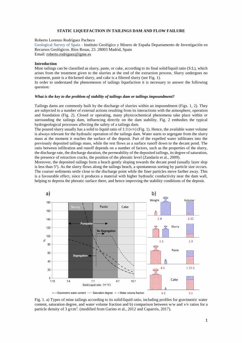
Static slope failure happens when the imposed stress on the embankment or foundation exceeds the peak
of effective shear stress-shear strain (strength-deformation) (Figs. 3, 4). Two main factors affecting the
static stability of slope are the shear strength of tailings dam and pore pressure. Static liquefaction refers to
the process whereby a contractive granular material (soils, tailings, gravels, loess, etc.), saturated in more
than 80%, loses its strength in response to an applied static stress. A clear instability (flow failure or mud
flow failure) appears when permanent loading is higher than the residual shear stress Su in undrained
conditions (Fig. 3, 4). The variety of trigger elements causing static liquefaction includes: increase of pore
pressure due to excessive dam rising rate (m/years) and other processes that alter the stress state of the
tailings dam where the load exceeds the peak of the shear stress (resistance)- shear strain (deformation) of
the material: 1) overtopping, 2) internal erosion, 3) erosion of the dam toe, 4) collapse of foundation, 5)
injection of water due to a drainage system failure, 6) increase in the water table due to the extraordinary
contributions of rain, thaw and increased of the metallurgical production, 7) collapse of tailings by the
increase of the saturation due to the input of groundwater, etc. (Figs. 4). However, it is important to
recognize that in all cases, whatever the triggering mechanism, the forces that ultimately drive the
liquefaction and the flow failure of liquefied material are permanent or gravitational. In this sense, the types
of liquefaction "dynamic" or "static" do not differ at all and hence their effects are identical.
Fig. 3. Geotechnical response of sediment in tailings dam basins under undrained conditions. Illustration of the cyclical
mobility and liquefaction cases, where (a) material under dilatant conditions, (b) material under contractive conditions
and τ0 < S
u, and (c) material under contractive conditions and τ
0 > S
u. τ shear-stress resistance of the material; γ shear
strain; τ0 initial shear-stress resistance of the material, due to permanent—gravitational—loadings; S
u residual shear
stress (modified from Oldecop and Rodríguez, 2006) and d) stress-strain response of a saturated, contractive sandy soil,
under static and cyclic loading. The left plot refers to shear loading and the right plot to normal loading (adapted from
Olson and Stark, 2003). Su(yield) yield shear strength, S
u(LIQ) liquefied shear strength.
5
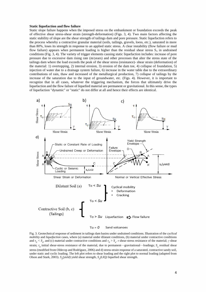
Fig 4. The sketch shows different mechanisms or processes that cause static liquefaction a) Tailings dam failure by
internal erosion (piping), b) tailings dam failure by overtopping, water overflow causes the erosion of the outer face, c)
tailings dam failure by hydric erosion of the toe. In all shown cases, the shear stresses increase on the tailings till
reaching the instability and static liquefaction may occur (τ is the shear stress and γ is the shear strain or deformation
(modified from Oldecop and Rodríguez, 2006, Caparrós, 2017, Oldecop and Rodríguez, 2018), and d) the three zones
where the dam can fail.
Internal erosion by piping
Figs. 4a and 5a illustrates the internal erosion by piping. Internal erosion refers to the soil fine particle
movement by water flow within sediments (tailings). It can take place in an embankment, foundation, or
contact area between embankment and foundation. In any case, hydraulic gradient and specific material
susceptibility—such as plasticity and particle gradation—play a critical role. The initiation of this process
starts when the material is susceptible to it and the onset of critical stress and hydraulic load are achieved.
Material susceptibility is the relative erosion resistance and dispersiveness of a soil. The critical hydraulic
load is related to the hydraulic energy required to invoke a mechanism of internal erosion, by means of
seepage flow through the tailings dam or foundation. The critical stress condition is related to the ability to
resist the effective stress, providing its spatial and temporal variability within the body of the dam. After
the internal erosion initiates, it can progress by forming a roof and concentrated leak, which can lead to a
breaching of the tailings dam.
In the case of tailings dams due to water regrowth, this process may be favoured by the preferential flow
through contacts between continuous dams. Horizontal flow may exist due to the existence of confined
water layer or horizons. The process of internal erosion is favoured by the acid mine drainage (AMD) and
the recirculation of water that is a common practice in mining industry. The recirculated waters have greater
dissolution capacity.
Hydric erosion of the dam toe
Some tailings dams are located at valley sites or close to watercourses—permanent or ephemeral. In those
cases, the hydric erosion of the dam toe can progressively aggravate dam instability, as shown in Fig. 2b.
In most flow failure cases due to static liquefaction, the tailings dams are in these conditions.
Overtopping and crest erosion
Crest erosion, crest subsidence, poor management of the lagoon, or major climatic events can suddenly
increase the water level until exceeding the dam crest. Overtopping normally results from design error or
waves due to strong wind or earth/rock slide into the reservoir (tailings basin). In general, sustained
overtopping results in a more catastrophic failure (Figs. 4c, 5b). Sustained overtopping can occur due to
water level increase in the tailings dam lagoon, while wave overtopping appears when a wave washes over
the crest (Fig. 4c, 5b).
6
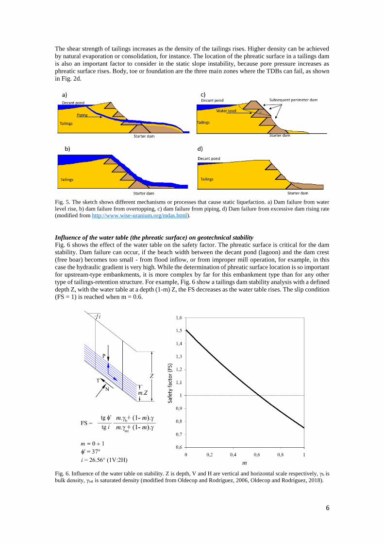
The shear strength of tailings increases as the density of the tailings rises. Higher density can be achieved
by natural evaporation or consolidation, for instance. The location of the phreatic surface in a tailings dam
is also an important factor to consider in the static slope instability, because pore pressure increases as
phreatic surface rises. Body, toe or foundation are the three main zones where the TDBs can fail, as shown
in Fig. 2d.
Fig. 5. The sketch shows different mechanisms or processes that cause static liquefaction. a) Dam failure from water
level rise, b) dam failure from overtopping, c) dam failure from piping, d) Dam failure from excessive dam rising rate
(modified from http://www.wise-uranium.org/mdas.html).
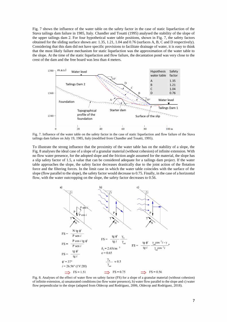
Influence of the water table (the phreatic surface) on geotechnical stability
Fig. 6 shows the effect of the water table on the safety factor. The phreatic surface is critical for the dam
stability. Dam failure can occur, if the beach width between the decant pond (lagoon) and the dam crest
(free boar) becomes too small - from flood inflow, or from improper mill operation, for example, in this
case the hydraulic gradient is very high. While the determination of phreatic surface location is so important
for upstream-type embankments, it is more complex by far for this embankment type than for any other
type of tailings-retention structure. For example, Fig. 6 show a tailings dam stability analysis with a defined
depth Z, with the water table at a depth (1-m) Z, the FS decreases as the water table rises. The slip condition
(FS = 1) is reached when m = 0.6.
Fig. 6. Influence of the water table on stability. Z is depth, V and H are vertical and horizontal scale respectively, γb is
bulk density, γsat is saturated density (modified from Oldecop and Rodríguez, 2006, Oldecop and Rodríguez, 2018).
7
Fig. 7 shows the influence of the water table on the safety factor in the case of static liquefaction of the
Stava tailings dam failure in 1985, Italy. Chandler and Tosatti (1995) analysed the stability of the slope of
the upper tailings dam 2. For four hypothetical water table positions, shown in Fig. 7, the safety factors
obtained for the sliding surface shown are: 1.35, 1.21, 1.04 and 0.76 (surfaces A, B, C and D respectively).
Considering that this dam did not have specific provisions to facilitate drainage of water, it is easy to think
that the most likely failure mechanism for static liquefaction was the approximation of the water table to
the slope. At the time of the static liquefaction and flow failure, the decantation pond was very close to the
crest of the dam and the free board was less than 4 meters.
Fig. 7. Influence of the water table on the safety factor in the case of static liquefaction and flow failure of the Stava
tailings dam failure on July 19, 1985, Italy (modified from Chandler and Tosatti, 1995).
To illustrate the strong influence that the proximity of the water table has on the stability of a slope, the
Fig. 8 analyses the ideal case of a slope of a granular material (without cohesion) of infinite extension. With
no flow water presence, for the adopted slope and the friction angle assumed for the material, the slope has
a slip safety factor of 1.5, a value that can be considered adequate for a tailings dam project. If the water
table approaches the slope, the safety factor decreases drastically due to the joint action of the flotation
force and the filtering forces. In the limit case in which the water table coincides with the surface of the
slope (flow parallel to the slope), the safety factor would decrease to 0.75. Finally, in the case of a horizontal
flow, with the water outcropping on the slope, the safety factor decreases to 0.56.
Fig. 8. Analyses of the effect of water flow on safety factor (FS) for a slope of a granular material (without cohesion)
of infinite extension, a) unsaturated conditions (no flow water presence), b) water flow parallel to the slope and c) water
flow perpendicular to the slope (adapted from Oldecop and Rodríguez, 2006, Oldecop and Rodríguez, 2018).
8
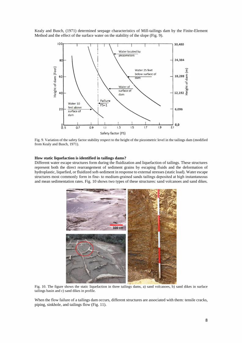
Kealy and Busch, (1971) determined seepage characteristics of Mill-tailings dam by the Finite-Element
Method and the effect of the surface water on the stability of the slope (Fig. 9).
Fig. 9. Variation of the safety factor stability respect to the height of the piezometric level in the tailings dam (modified
from Kealy and Busch, 1971).
How static liquefaction is identified in tailings dams?
Different water escape structures form during the fluidization and liquefaction of tailings. These structures
represent both the direct rearrangement of sediment grains by escaping fluids and the deformation of
hydroplastic, liquefied, or fluidized soft-sediment in response to external stresses (static load). Water escape
structures most commonly form in fine‐ to medium‐grained sands tailings deposited at high instantaneous
and mean sedimentation rates. Fig. 10 shows two types of these structures: sand volcanoes and sand dikes.
Fig. 10. The figure shows the static liquefaction in three tailings dams, a) sand volcanoes, b) sand dikes in surface
tailings basin and c) sand dikes in profile.
When the flow failure of a tailings dam occurs, different structures are associated with them: tensile cracks,
piping, sinkhole, and tailings flow (Fig. 11).
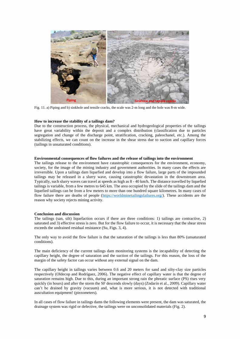
9
Fig. 11. a) Piping and b) sinkhole and tensile cracks, the scale was 2-m long and the hole was 8-m wide.
How to increase the stability of a tailings dam?
Due to the construction process, the physical, mechanical and hydrogeological properties of the tailings
have great variability within the deposit and a complex distribution (classification due to particles
segregation and change of the discharge point, stratification, cracking, paleochanel, etc.). Among the
stabilizing effects, we can count on the increase in the shear stress due to suction and capillary forces
(tailings in unsaturated conditions).
Environmental consequences of flow failures and the release of tailings into the environment
The tailings release to the environment have catastrophic consequences for the environment, economy,
society, for the image of the mining industry and government authorities. In many cases the effects are
irreversible. Upon a tailings dam liquefied and develop into a flow failure, large parts of the impounded
tailings may be released in a slurry wave, causing catastrophic devastation in the downstream area.
Typically, such slurry waves can travel at speeds as high as 8 - 40 km/h. The distance travelled by liquefied
tailings is variable, from a few metres to 645 km. The area occupied by the slide of the tailings dam and the
liquefied tailings can be from a few meters to more than one hundred square kilometres. In many cases of
flow failure there are deaths of people (https://worldminetailingsfailures.org/). These accidents are the
reason why society rejects mining activity.
Conclusion and discussion
The tailings (san, silt) liquefaction occurs if there are three conditions: 1) tailings are contractive, 2)
saturated and 3) effective stress is zero. But for the flow failure to occur, it is necessary that the shear stress
exceeds the undrained residual resistance (Su, Figs. 3, 4).
The only way to avoid the flow failure is that the saturation of the tailings is less than 80% (unsaturated
conditions).
The main deficiency of the current tailings dam monitoring systems is the incapability of detecting the
capillary height, the degree of saturation and the suction of the tailings. For this reason, the loss of the
margin of the safety factor can occur without any external signal on the dam.
The capillary height in tailings varies between 0.6 and 20 meters for sand and silty-clay size particles
respectively (Oldecop and Rodríguez, 2006). The negative effect of capillary water is that the degree of
saturation remains high. Due to this, during an important strong rain the phreatic surface (PS) rises very
quickly (in hours) and after the storm the SF descends slowly (days) (Zndarín et al., 2009). Capillary water
can’t be drained by gravity (vacuum) and, what is more serious, it is not detected with traditional
auscultation equipment! (piezometers).
In all cases of flow failure in tailings dams the following elements were present, the dam was saturated, the
drainage system was rigid or defective, the tailings were on unconsolidated materials (Fig. 2).
10
The EU recommends for upstream tailings dams raising rate restrictions less than 5 m/years (this is equals
to 14 mm/day), to avoid insufficient consolidation and pore pressure build-up (EU, 2009).
The key is water balance and tailings dam-water cycle. Why?
Input = Output ± Storege coefficient (4)
The water Output has to be always bigger than the Input to guarantee that the tailings are in unsaturated
conditions, fundamentally in the area near the dam (beach, Figs. 2). The hydraulic operation of the tailings
dam is decisive for its stability during operation and after tailings dam closure. Infiltration and
evapotranspiration are the two key parameters.
Fundamental controls on tailings consolidation and water Output are exerted by the bulk tailings properties
of grain size, packing, stratification, permeability, desiccation cracks and strength, which together
determine whether consolidation will occur and, if so the course it follows, and by external disturbances
which act to trigger liquefaction and fluidization. The liquefaction and fluidization of tailings (sand, silt,
silty-clay) usually accompanies the collapse of loosely packed cross‐bedded deposits (stratification in
tailings dam basin due to change in point of discharge). This collapse is commonly initiated by water forced
into the units as underlying beds, especially sands and silt, consolidate. The consolidation of subjacent units
is often triggered by the rapid deposition of the tailings itself, although earthquakes or other disturbances
are probably influential in some instances.
Reference Caparrós, A.V. 2017. Rheology of Pb-Zn post-flotation wastes in the Sierra de Cartagena – La Unión (SE Spain).
Doctoral thesis. Universidad Polytechnic de Cartagena, Murcia, Spain.
Chandler, R. J. y Tosatti, G. 1995. The Stava dams failure, Italy, July, 1985. Proc. Instn. Civ. Engng, 113, 67-79.
European Commission, 2009. Report. Reference document on the best available techniques. Management of tailings
and waste-rock in mining activities, Ref. Doc. Best Available Tech. 511,
(http://eippcb.jrc.ec.europa.eu/reference/BREF/mmr_adopted_0109.pdf).
Garino , L., Rodari, G., Oldecop, L., Zabala, F., and Rodari, R. 2012. Almacenamiento de colas mineras filtradas.
Primera experiencia en Argentina. Congreso argentine de mecánica de suelos e ingeniería geotécnica, CAMSIG XXI,
Rosario, Santa Fe, Argentina, pp. 1-10.
Kealy, C. D., & Busch, R. A. 1971. Determining Seepage Characteristics of Mill-Tailings Dams by the Finite-Element
Method. U.S. Bureau of Mines, Report of Investigations 7477, 124.
Oldecop, L., Rodríguez, R., 2006. Estabilidad y seguridad de depósitos de residuos mineros. In: Los residuos minero
metalúrgicos en el medio ambiente. Rodríguez, R., García-Cortés, A. (Eds.), Instituto Geológico y Minero de España
(IGME), pp. 197-243. https://www.researchgate.net/publication/263741877_Los_residuos_minero-
metalurgicos_en_el_medio_ambiente
Oldecop, L. and Rodríguez, R. (2018). Curso de postgrado temas especiales en ingeniería civil: cierre de presas de
relaves y remediación de pasivos ambientales mineros, 5 al 10 de marzo de 2018. San Juan, Argentina.
Rodríguez, R., 2002. Estudio experimental de flujo y transporte de cromo, níquel y manganeso en residuos de la zona
minera de Moa (Cuba): influencia del comportamiento hidromecánico. Ph.D. Thesis, Universidad Politécnica de
Cataluña, Barcelona, Spain.
Rodríguez, R., Candela, L., 2004. Changes of groundwater chemistry due to metallurgical activities in the alluvial
aquifer in the Moa are (Cuba). Environmental Geology, 46, 71-82.
Rodríguez, R., Candela, L., Lloret, A., 2004. Experimental system for studying the hydromechanical behaviour of
porous media. Vadose Zone Journal 4, 345-353.
Rodríguez, R., 2006. Hydrogeotechnical characterization of a metallurgical waste. Canadian Geotechnical Journal 43,
1042-1060.
Rodríguez, R., Candela, L., Lloret, A., 2006b. Apparatus for evaluation of haydomechanical behaviour of porous media
subjected to environmental changes. Geotechnical Testing Journal 29, 9-20.
Rodríguez, R., García-Cortés, A., 2006. Los residuos minero metalúrgicos en el medio ambiente. Publisher Instituto
Geológico y Minero de España (IGME). Madrid, Spain.
Zandarín, M.T., Oldecop, L.A., Rodríguez, R., Zabala, F., 2009. The role of capillary water in the stability of tailings
dams. Engineering Geology, 105(1), 108–118. doi: 10.1016/j.enggeo.2008.12.003.