Embed Size (px)
Citation preview

International Journal of Current Engineering and Technology E-ISSN 2277 – 4106, P-ISSN 2347 – 5161 ©2015 INPRESSCO®, All Rights Reserved Available at http://inpressco.com/category/ijcet
Research Article
462| International Journal of Current Engineering and Technology, Vol.5, No.1 (Feb 2015)
Static & Free Vibration Analysis of an Isotropic and Orthotropic Thin Plate using Finite Element Analysis (FEA)
Ehab N. Abbas†*, Mohammad Qasim Abdullah‡ and Hatem R. Wasmi‡
†Studies & Planning & Follow-Up Dept., MHESR, Baghad, Iraq ‡Dept. of Mechanical Engineering, University of Baghdad, Iraq
Accepted 24 Feb 2015, Available online 25 Feb 2015, Vol.5, No.1 (Feb 2015)
Abstract This paper describes the static and dynamic analysis of thin isotropic and orthotropic CCCC plates. Two methods of analyses were carried out and compared. One is the theoretical analysis, the second is the finite element analysis with the conventional finite element modeling approach. The theoretical analysis was divided into stress, deflection, and frequencies calculations. The analysis was carried out using the classical thin plate theory. For the finite element analysis, the analyses were performed using the ANSYS finite element software. The first Five natural frequencies were obtained for the plates. For all these methods, the theoretical and numerical analyses are to be compared. Keywords: Finite element analysis (FEA), Isotropic, Orthotropic, Thin plate, Static analysis, Free Vibration analysis. Introduction
1 Finite element analysis (FEA) is a powerful computational technique used for solving engineering problems having complex geometries that are subjected to general boundary conditions. While the analysis is being carried out the system is discretized into a finite number of parts known as elements by expressing the unknown field variable in terms of the assumed approximating functions within each element. For each element, systematic approximate solution is constructed by applying the variational or weighted residual methods. These functions (also called interpolation functions) are, included in terms of field variables at specific points referred to as nodes. Modeling is useful for solving complex solid structures. The present work deals with the analysis of an isotropic rectangular element being considered as a plane stress condition, under fully clamed boundary condition. Throughout the analysis, the master element which is four noded quadrilateral elements, are used. Later, experiments have been conducted for same, using ANSYS. Finally, results have been checked with exact results obtained from Kirchhoff plate theory. Orthotropic plates are widely used in civil infrastructure systems and other structural applications because of their advantageous features such as high ratio of stiffness and strength to weight. Thus, the knowledge of their free vibration
*Corresponsing author: Ehab N. Abbas is working as Assistant lecturer, Dr. Mohammad Qasim Abdullah as Professor and Dr. Hatem R. Wasmi as Assistant Professor
characteristic is very important to the structural designers. The vibration of orthotropic plate is more complicated due to the material anisotropy. Thus, the solutions of rectangular plates with four edges clamped boundary conditions are obtained by substituting the boundary conditions that satisfy the support modes of the plate to derive the fundamental natural frequency equation for the plate. Comparison studies are performed between the present results. The effects of materials, dimensions on the natural frequency of the orthotropic plates are investigated and discussed.
Kirchhoff plate theory
The basic assumptions being considered under classical Kirchhoff’s plate bending theory are identical to the Euler-Bernoulli beam theory assumptions. Consider the differential segment from the plate by planes perpendicular to the x axis as shown in Figure 1.
Figure 1 Out of plane stresses
Load ‘q’ causes the plate to deform in the z direction and the deflection ‘w’ of point ‘P’ is assumed to be a

Ehab N. Abbas et al Static & Free Vibration Analysis of an Isotropic and Orthotropic Thin Plate using Finite Element Analysis
463| International Journal of Current Engineering and Technology, Vol.5, No.1 (Feb 2015)
function of x and y only, that is, w=w(x,y) and the plate does not stretch in the z direction. The conventional assumptions are considered with the Kirchhoff theory, these assumptions result in the reduction of a three-dimensional plate problem into a two dimensional one. Consequently, the governing equation of plate can be derived in a simple and straight- forward manner. Governing equations for deflection and Frequency The aforementioned assumptions of Kirchhoff plate theory makes it easy to drive the basic equations for thin plates. According to assumption of the theory the moment/curvature expressions was used to obtain the final form of governing partial differential equation for isotropic thin-plate in bending which it is: d4w/dx4 +2d4w/dx2 dy2 + d4w/dy4)= p (x,y) / D (1) In orthotropic materials stressed in one of the principal directions, the lateral deformation in the other principal directions could be smaller or larger than the deformation in the direction of the applied stress depending on the material properties also; the magnitude of the shearing deformation is independent of the elastic constants. An orthotropic material is characterized by the fact that the mechanical elastic properties have two perpendicular planes of symmetry. Due to these only four elastic constants E1, E2, G12, 12 are independent. The plate differential Eq. (1) becomes (Dx d4w/dx4 +2H d4w/dx2 dy2 + Dy d4w/dy4)= p (x,y) (2) The dynamic response for any type of a structure can be reduced to a set of mode shapes, each with an associated modal frequency and damping. These modal parameters constitute the dynamic properties of the structure and provide for a complete dynamic description of the structure. The method based on superposition of appropriate Levy type solutions for the analysis of rectangular plates was first illustrated by Timoshenko and Krieger. Gorman extended this method to the free vibration analysis of isotropic, clamped orthotropic rectangular plates,… (Maan H. Jawad et al, 2004). The governing differential equation for isotropic plate is
D (d4w/dx4 +2d4w/dx2 dy2 + d4w/dy4)= 2 w (3)
Where w is displacement in positive z – direction, is the mass per unit area of the plate, 2 is the fundamental natural frequency. A direct solution of such equation might be difficult and most of the reported solutions are based on numerical and for orthotropic. For the orthotropic thin plate by using the love-Kirchhoff's hypotheses, the differential equation of the free vibrations has the form (Iuliana Sprintu, Ion Fuiorea et al, 2014):
D1 d4w/dx4 +2D3 d4w/dx2 dy2 + D2 d4w/dy4 - 2 h w (4) Where D1= E1 h3/ 12(1-1221) , D2= E2 h3/ 12(1-1221) , D66 = G12 h3 / 12 D12= 12 D2 = 21 D1 , D3= D12 + 2D66 And the coefficient 21 can be determined according to following relation 12 / E1 = 21/ E2 Analytical solution Consider a rectangular plate with length a and width b, it is assumed that the four edges are fully clamped conditions, so Levy-type solution is used for this case, the boundary conditions are: w= dw/dx = 0 for x=0 and x=a , w = dw/dy=0 for y=0 and y=b (5) This approach used to obtain the exact solution that satisfies the prescribed boundary conditions. Let us mention that Reddy proposed solution for equation (2) with boundary condition (5) as (Y.F. Xing, B. Liu et al, 2009). Using Steel with data (1) in table (1) we get the maximum value of the deflection w(a/2,b/2) =0.02306 mm for isotropic plate. For the case of modal analysis, (Arthur W. Leissa et al, 1969) presented the nondimensional frequency parameter, K, based on the classical Voigt. The respective classical natural frequencies for thin isotropic plate are defined by mn= K/a2 (D/h)1/2 (6) where K2 = (505.0683+285.7143/P + 504.0683/P3) , P = b/a =aspect ratio The natural frequencies of orthotropic plate of size a × b of equation (4) are defined for fully clamped boundary conditions as (Arther W. Leissa et al, 1969) by:
=49 p a4/ 256 x 8(7Dx + 4H+ 7Dy) Where H= D1 +2Dxy (7) FEA formulation for 4-noded quadrilateral element Isotropic and orthotropic four node quadrilateral element is having one node at each corner as shown in Figure (2). There are three degrees of freedom at each node, therefore, the element has twelve degrees of freedom and the displacement function of the element can be represented by a polynomial having twelve terms.

Ehab N. Abbas et al Static & Free Vibration Analysis of an Isotropic and Orthotropic Thin Plate using Finite Element Analysis
464| International Journal of Current Engineering and Technology, Vol.5, No.1 (Feb 2015)
Table 1 Mechanical Properties &dimensions details for FourSix types of plates
Example No.
Isotropic Plates Data
a (m)
b (m)
h (m)
E (pa)
G (pa)
Loading (pa)
Mass Density Kg/m3
B.C.
1 10 10 0.05 200e9
0.3 -- 0.00419e
6 8000 CCCC
Example No.
Orthotropic Plates Data
a (m)
b (m)
h (m)
E1 (pa)
E2 (pa)
12
G12 (pa)
Loading (pa)
Mass Density Kg/m3
B.C.
2 300 200 1.45 22051e6 18512e6 0.071 8642e6
0.00419 e6
800
CCCC 3 1 1.2 0.0004 185e9 10.5e9 0.28 7.3 e9 1600 4 1 1.2 0.0004 208e9 18.5e9 0.23 5.7e9 2000 5 1 2 0.0004 208e9 18.5e9 0.23 5.7e9 2000
The stiffness matrix given by
[k]e = [B]T [D] [B] dx dy ={ [G]T } ( [Q]T [C] [Q] dx dy) [G]-1 (8) In the case of orthotropic plate element [k]e = 1/15 a b [R] {Dx [k1] + Dy [k2] + Dxy [k3] + Gxy [k4]} [R] (9) The stresses at any point in the plate are given by:
[
] = {} = [D] {}
Figure 2 Rectangular element geometry
Figure 3 Typical element used in the analysis
ANSYS analysis
Finite element analysis software ANSYS is a capable way to analyze a wide range of different problems. In this study, finite element analysis is conducted using ANSYS software. An 4 and 8 node shell elements, (specified as SHELL 181 , 281 respectively in ANSYS) is used throughout the study of isotropic and orthotropic plates. The second element has eight nodes with six degrees of freedom at each node (Fig.3): translations in the x, y, and z axes, and rotations about the x, y, and z-axes. SHELL281 is well-suited for linear, large rotation, and large strain nonlinear applications.
Numerical Examples and Discussion
Example (1): A square fully clamped isotropic plate (Data 1). Example (2): Rectangular fully clamped orthotropic of single layer plate (Data 2). Example (3): Rectangular fully clamped orthotropic of single layer plate (Data 3). Example (4): Rectangular fully clamped orthotropic of single layer plate (Data 4). Example (5): Rectangular fully clamped orthotropic of single layer plate (Data 5). First, we presented the comparative results between the numerical and analytical max. deflection values, for the isotropic plate of mentioned dimensions and boundaries subjected to the uniform pressure p= 4190 pa. by observing the results from figure (5), the agreement between the two solutions are shown in table (2). Max. normal stress is presented also in the table (6).
Figure 4 Boundary conditions of Levy-type plate
Table 2 Max. deflection & max. normal stress for 10x10m isotropic plates
Maximum deflection, m Analytical Solution Present FEM
0.0230604 0.023103
Maximum normal stress, Pa
Analytical Solution Present FEM -- 0.406e8

Ehab N. Abbas et al Static & Free Vibration Analysis of an Isotropic and Orthotropic Thin Plate using Finite Element Analysis
465| International Journal of Current Engineering and Technology, Vol.5, No.1 (Feb 2015)
Figure 5 Max. deflection due to uniform loading for CCCC 10x10m isotropic Plate
Figure 6 Max. normal stress for CCCC 10x10 m isotropic Plates
Table 3 Max. normal stress for orthotropic plates from FEM
Plate type Ex2 Ex3 Ex4 Ex5 Stresses(Pa) 0.343e8 0.134e11 0.136e11 0.133e11
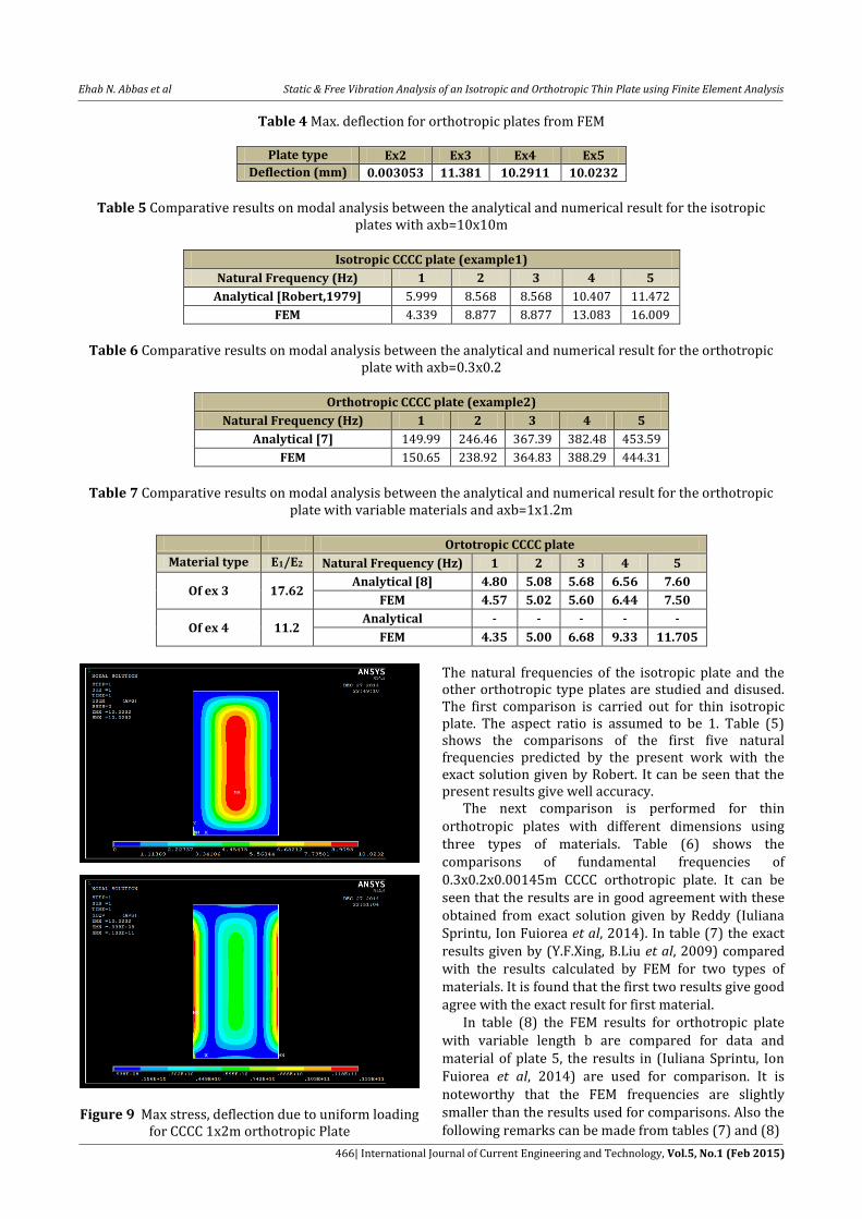
The variations in deflections of the orthotropic plates with fully clamped boundary condition are then illustrated in table (4). Figures (7), (8) and (9) showed the max deflection contours plots and maximum normal stress for mentioned types of orthotropic plates. The values for maximum deflection at W(a/2,b/2) is larger than the isotropic case.
Figure 7 Max. stress, deflection due to uniform loading
for CCCC 0.3x0.2m orthotropic
Figure 8 Max stress, deflection due to uniform loading for CCCC 1x1.2m M1 orthotropic
Ehab N. Abbas et al Static & Free Vibration Analysis of an Isotropic and Orthotropic Thin Plate using Finite Element Analysis
466| International Journal of Current Engineering and Technology, Vol.5, No.1 (Feb 2015)
Table 4 Max. deflection for orthotropic plates from FEM
Plate type Ex2 Ex3 Ex4 Ex5
Deflection (mm) 0.003053 11.381 10.2911 10.0232
Table 5 Comparative results on modal analysis between the analytical and numerical result for the isotropic
plates with axb=10x10m
Isotropic CCCC plate (example1)
Natural Frequency (Hz) 1 2 3 4 5
Analytical [Robert,1979] 5.999 8.568 8.568 10.407 11.472
FEM 4.339 8.877 8.877 13.083 16.009
Table 6 Comparative results on modal analysis between the analytical and numerical result for the orthotropic
plate with axb=0.3x0.2
Orthotropic CCCC plate (example2)
Natural Frequency (Hz) 1 2 3 4 5
Analytical [7] 149.99 246.46 367.39 382.48 453.59
FEM 150.65 238.92 364.83 388.29 444.31
Table 7 Comparative results on modal analysis between the analytical and numerical result for the orthotropic
plate with variable materials and axb=1x1.2m
Ortotropic CCCC plate
Material type E1/E2 Natural Frequency (Hz) 1 2 3 4 5
Of ex 3 17.62 Analytical [8] 4.80 5.08 5.68 6.56 7.60
FEM 4.57 5.02 5.60 6.44 7.50
Of ex 4 11.2 Analytical - - - - -
FEM 4.35 5.00 6.68 9.33 11.705
Figure 9 Max stress, deflection due to uniform loading for CCCC 1x2m orthotropic Plate
The natural frequencies of the isotropic plate and the other orthotropic type plates are studied and disused. The first comparison is carried out for thin isotropic plate. The aspect ratio is assumed to be 1. Table (5) shows the comparisons of the first five natural frequencies predicted by the present work with the exact solution given by Robert. It can be seen that the present results give well accuracy. The next comparison is performed for thin orthotropic plates with different dimensions using three types of materials. Table (6) shows the comparisons of fundamental frequencies of 0.3x0.2x0.00145m CCCC orthotropic plate. It can be seen that the results are in good agreement with these obtained from exact solution given by Reddy (Iuliana Sprintu, Ion Fuiorea et al, 2014). In table (7) the exact results given by (Y.F.Xing, B.Liu et al, 2009) compared with the results calculated by FEM for two types of materials. It is found that the first two results give good agree with the exact result for first material. In table (8) the FEM results for orthotropic plate
with variable length b are compared for data and material of plate 5, the results in (Iuliana Sprintu, Ion Fuiorea et al, 2014) are used for comparison. It is
noteworthy that the FEM frequencies are slightly smaller than the results used for comparisons. Also the
following remarks can be made from tables (7) and (8)

Ehab N. Abbas et al Static & Free Vibration Analysis of an Isotropic and Orthotropic Thin Plate using Finite Element Analysis
467| International Journal of Current Engineering and Technology, Vol.5, No.1 (Feb 2015)
Table 8 Comparative results on modal analysis between the analytical and numerical result for the orthotropic plate with variable b for example (5)
Orthotropic CCCC plates
b Natural Frequency (Hz) 1 2 3 4 5
1 Analytical [8] 4.87 5.50 6.68 7.91 8.15
FEM 4.47 5.707 8.38 11.77 12.41
2 Analytical [8] 4.75 4.82 5.00 5.32 5.78
FEM 4.23 4.37 4.71 5.33 6.31
- Regardless of boundary condition the fundamental
frequencies are increased by increasing the modulus ratio (E1/E2).
- Regardless of modulus ratio frequencies are increased by increasing the side to thickness ratio b/h. the effect of thickness ratio becomes significant for thicker plate with high modulus ratio. It means that by keeping (a) as a constant and (b) kept on increasing natural frequency of the plate decrease. This is due to the effect of shear deformations.[11].
Figure 10 First Four modes for the 10x10m CCCC isotropic plate
Conclusions This paper mainly focused on the finite element model for deflection and natural frequency for isotropic and orthotropic rectangular and square plate. During the analysis plate dimension b varies from 1 to 2 m under same plate type and compared with exact solutions, which are calculated from plate theory. Analysis results showed convergence towards the exact solution as well. Hence, we can conclude that the present analysis by FEM is a good approximate method for analyzing plate in deflection and vibration. Equations are difficult to solve for orthotropic types plates. It can be concluded that the present analysis is not only accurate but also simple in predicting the natural frequencies of orthotropic plates. References Vanam B.C.L., Rajyalakshmi M., Inala R. (2012), Static analysis
of an isotropic rectangular plate using FEM., Journal of Mechanical Engineering Research, 4 (4), pp 148-162.
K. O. Njoku, J. C. Ezeh, O. M. Ibearugbulem, L. O. Ettu, L. Anyaogu (2013), Free vibration analysis of thin rectangular isotropic CCCC plate using Taylor series formulated shape function in Galerkin's method, Academic Research International, 4 (4), pp 126-132.
Neffati M. Werfalli, Abobaker A. Karoud (2011), Free Vibration Analysis of Rectangular Plates Using Galerkin's-Based Finite Element Method, International Journal of Mechanical Engineering, 2 (2), pp 59-67.
Devidas R. Patil, P.G.Damle, Dr. D.S.Deshmukh (2014), Vibration analysis of composite plate at different boundary conditions, International Journal of Innovative Research in Science Engineering and Technology, 3 (12), pp 18089-18094.

Ehab N. Abbas et al Static & Free Vibration Analysis of an Isotropic and Orthotropic Thin Plate using Finite Element Analysis
468| International Journal of Current Engineering and Technology, Vol.5, No.1 (Feb 2015)
C. Erdem Imrak, Ismail Gerdemel (2007), The problem of isotropic rectangular plate with four clamped edges, S¯adhan¯a , 32 (3), pp 181–186.
J. C. Ezeh, O. M. Ibearugbulem, K. O. Njoku, L. O. Ettu (2013), Dynamic analysis of isotropic SSSS plate using Taylor series shape function in Galerkin’s Functional, International Journal of Emerging Technology and Advanced Engineering, 3 (5), pp 372-375.
Iuliana Sprintu, Ion Fuiorea (2014), Comparative analysis of orthotropic plates, U.P.B. Sci. Bull. Series D, 76 (3), pp 25-32
Y.F. Xing, B. Liu (2009), New exact solutions for free vibrations of thin orthotropic rectangular plates, Journal of Composite Structures, 89 (4), pp 567-574.
S.B.Chikalthankar, I.I.Sayyad, V.M.Nandedkar (2013), Analysis of orthotropic plate by refined plate theory, International Journal of Engineering and Advanced Technology, 2 (6), pp 310-315.
R.P. Shimpi, H.G. Patel, A two variable refined plate theory for orthotropic plate analysis, pp 6783-6799
Huu-Tai Thai, Seung-Eock Kim (2012), Levy-type solution for free vibration analysis of orthotropic plates based on two variable refined plate theory, Journal of Applied Mathematical Modelling, 36, pp 3870–3882.
Dimitris Karamanlidis, Hung Le Themixed (1984), Finite element models for plate bending analysis: a new element and applications, Journal of Computers & Structures, 19 (4), pp 565-58
G.R. Liu a, X. Zhao, K.Y. Dai, Z.H. Zhong, G.Y. Li, X. Han (2008), Static and free vibration analysis of laminated composite plates using the conforming radial point interpolation method, Journal of Composites Science and Technology, 68, pp 354–36
Timoshenko S, Woinowsky-Krieger S. (1959), Theory of plates and shells, 2d ed, New York, McGraw-Hill.
Rudolph Szilard, Dr.-Ing., P.E. (2004), Theory Theories and Applications of Plate Analysis, by John Wiley & Sons, Inc.
Maan H. Jawad, Ph.D., P.E. President Global Engineering & Technology (2004), Design of plate and shell structure, by The American Society of Mechanical Engineers.
Arthur W. Leissa (1969), Vibration of Plates, Office of technology utilization, National Aeronautics And Space Administration.