Embed Size (px)
Citation preview
1202 | P a g e
STATIC AND DYNAMIC ANALYSIS OF COMPOSITE
ROTOR BLADE
Dr. M. Murali Krishna1, G. Siva Karuna
2
1Professor,
2Associate Professor, Department of Mechanical Engineering
Sai Ganapathi College of Engineering, (India)
ABSTRACT
A typical turbo machinery blade is essentially a rectangular plate of considerable pre-twist. Blades are being
developed in composite materials in order to achieve low weight and high strength construction. The main idea
of this work is to evaluate the properties of the blade during the twist and to sustain for the high wing forces
using composite material. In the present work rotor blade model has been created in Pro-E, static analysis is
used to find the maximum safe stress and deformations .modal analysis is used to find natural frequencies and
mode shapes. A composite is a structural material, which consists of combining two or more constituents in
order to obtain a combination of properties that cannot be achieved with any of the constituents acting alone.
Composite blades are made with unidirectional fibres parallel to the blade's long axis, as well as adaptive
configuration with fibre orientation in off-axis directions to affect bend-twist coupling developing concept
designs and analyzing the structural response of composite blades for different operating conditions is taken up
in this project. the result of static analysis is the safe design stress; the stress is calculated as 59.306N/mm2 for
corresponding blade twist, thickness and number of layers are 450, 5 mm and 5 layers respectively. Modal
analysis presents the mode shapes which changes with blade twist associated with a variation in natural
frequency.
Keywords: Composite fibre , Rotor blade, Vonmisess stress, Twist angle.
I. INTRODUCTION
Rotor blade is long airfoil that rotates to provide the lift that supports a helicopter in the air .The blades of a
helicopter are long, narrow airfoils with a high aspect ratio, a shape which minimises drag from tip vortices.
They generally contain a degree of washout to reduce the lift generated at the tips, where the airflow is fastest
and vortex generation would be a significant problem. Rotor blades are made out of various materials, including
aluminium, composite structure and steel or titanium with erosion shields along the leading edge. Applications
of the rotor blades includes, marine-propeller vanes, fans and blowers, gear cases, valves and strainers,
condenser shells, helicopter rotors, typical wind tunnel fan blades.
The objective is usually to make a component which is strong and stiff, often with a low density; commercial
material commonly has glass or carbon fibres in matrices based on the thermosetting polymers, such as epoxy
or polyester resins. Furthermore, in these composites the reasons for adding the fibres (or, in some cases,
particles) are often rather complex; for example, improvements may be sought in creep, wear, fracture
toughness, thermal stability, etc
1203 | P a g e
A composite is a structure material, which consists of combining two or more constituents in order to obtain a
combination of properties that cannot be achieved with any of the constituents acting alone .The constituents are
combined at a macroscopic level and or not soluble in each other. The constituents as well as the interface
between them are recognizable and it is the behaviour and properties of the interface that generally control the
properties of the composite. The main difference between a composite and an alloy is that in a composite retain
their properties, where as in alloys, constituent materials are soluble in each other and form a new material
which has different properties from their constituents. Wind turbine blades are most often fabricated by hand
using multiple layers of fibreglass cloth. The traditional method is for the sheets to be cut to shape, laid down in
a mold by hand, sprayed or rolled with resins, and finally cured.
1.1 Aim of The Project
It is planned to develop blade design that use carbon fibre to its fullest advantages by maximizing energy
capture while mitigating loads throughout the turbine system.
It is also planned to develop blade designs using hybrid carbon/fibreglass designs.
Developing the design requirements for composite combining the functional requirements and requirements
that arise out of using the composite material system
Developing the analytical design for composite blades
Modelling and analysis using FEM for different configurations and obtaining the optimized structure based
on static and dynamic analysis.
1.2 Problem Fromulation
The design of modern rotor includes choices of blade number, airfoils, chord and twist distributions, and
materials. Thin airfoils are desirable foe their high lift to drag ratios and are roughness tolerant, whereas thick
airfoils sacrifice some of these qualities to achieve the greater blade stiffness required for large machines. For
large commercial machines, the upwind, three-bladed rotor is the industry-accepted configuration. The design
parameters are taken from “NASA TECHNICAL PAPER 3641".the design parameters taken for the rotor blade
are length, width and thickness. The values are as follows:
Length=304.8mm
Width=76.2mm
Thickness=5.08 mm
Load calculations:-
The values required for the load calculations are taken from "code book 875_3''
Wind Load Calculations:
Wind pressure =0.6*
Wind velocity=150KMPH
Wind pressure =1041.83* N/mm2
Boundary conditions:-The blade is fixed at end at four holes
1204 | P a g e
II. MODELLING AND ANALYSIS OF ROTOR BLADE
Rotor blade is modelled by using the design package Pro/ENGINEER. In the Pro-e file is usually saved in
PART(.prt) format by default. To export the part to ANSYS we saved the part in IGES(.igs) format. usually we
save surfaces so that retrieval time and memory space required will be reduced .This saved part can be retrieved
in ANSYS and can be converted to volume so that the model represents the real time structure. This geometric
model should be converted to a finite element model in order to perform finite element analysis on it.
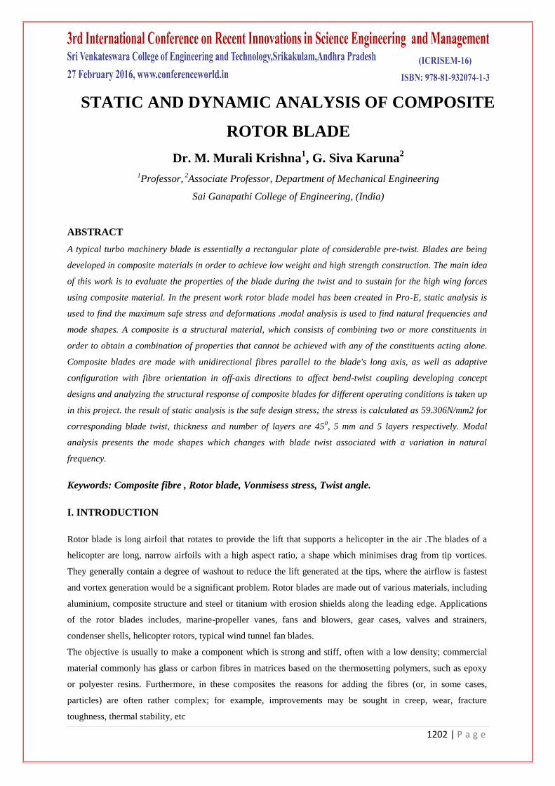
Carbon fibre -resign matrix is taken as composite material and modelling is done. Dimensions of the composite
rotor blade are length, width and thickness are 304.8, 76.2 and 5.08 mm respectively.
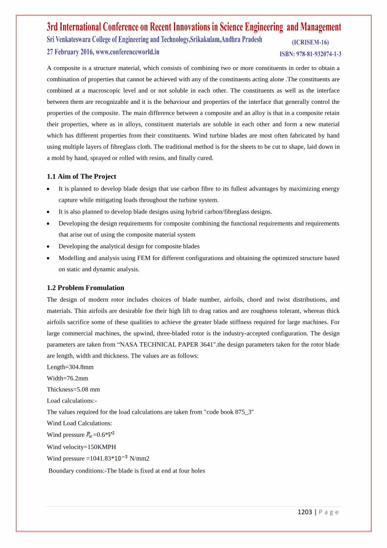
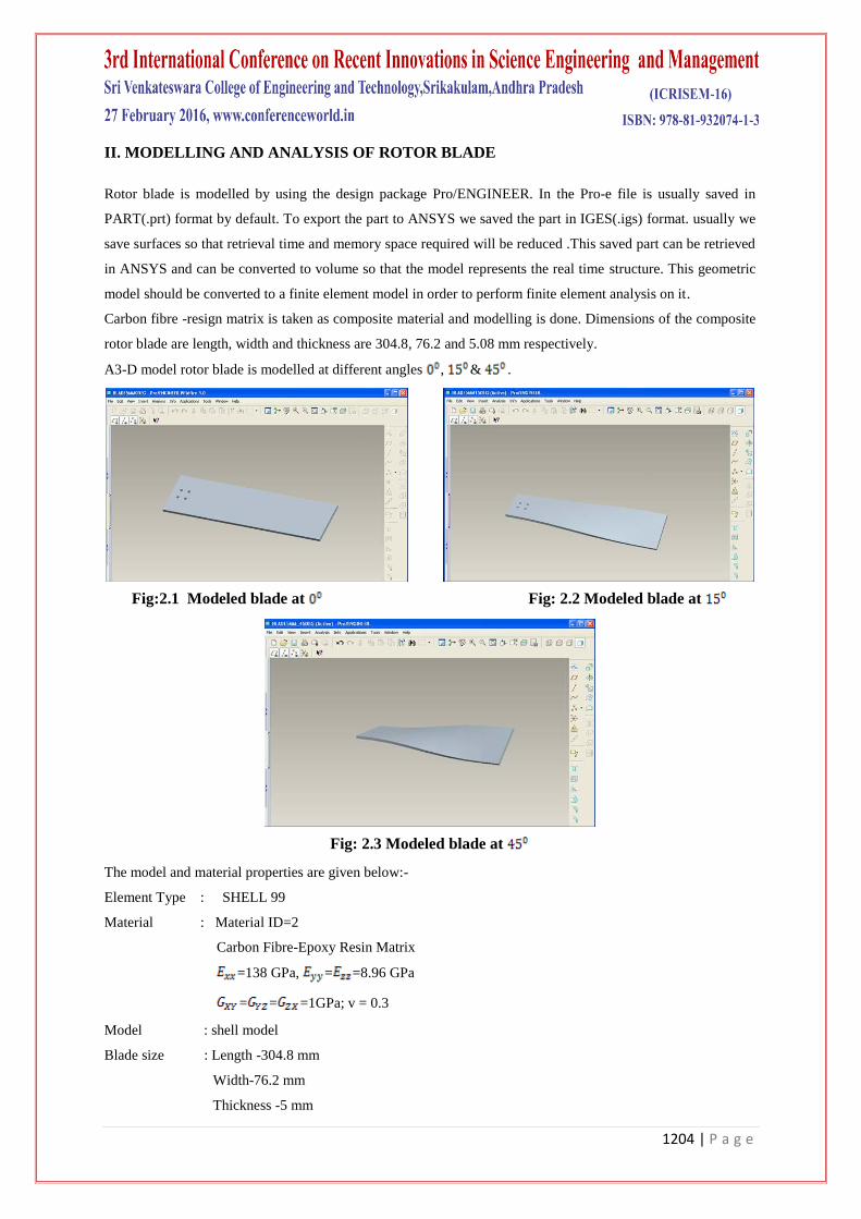
A3-D model rotor blade is modelled at different angles , & .
Fig:2.1 Modeled blade at Fig: 2.2 Modeled blade at
Fig: 2.3 Modeled blade at
The model and material properties are given below:-
Element Type : SHELL 99
Material : Material ID=2
Carbon Fibre-Epoxy Resin Matrix
=138 GPa, = =8.96 GPa
= = =1GPa; v = 0.3
Model : shell model
Blade size : Length -304.8 mm
Width-76.2 mm
Thickness -5 mm
1205 | P a g e
Above values are taken from the ''NASA TECHNICAL PAPER 3641''
Modelling : composite blade assembly.
Analysis : Static, dynamic and Natural modes of vibration
Fibre Orientation: , &
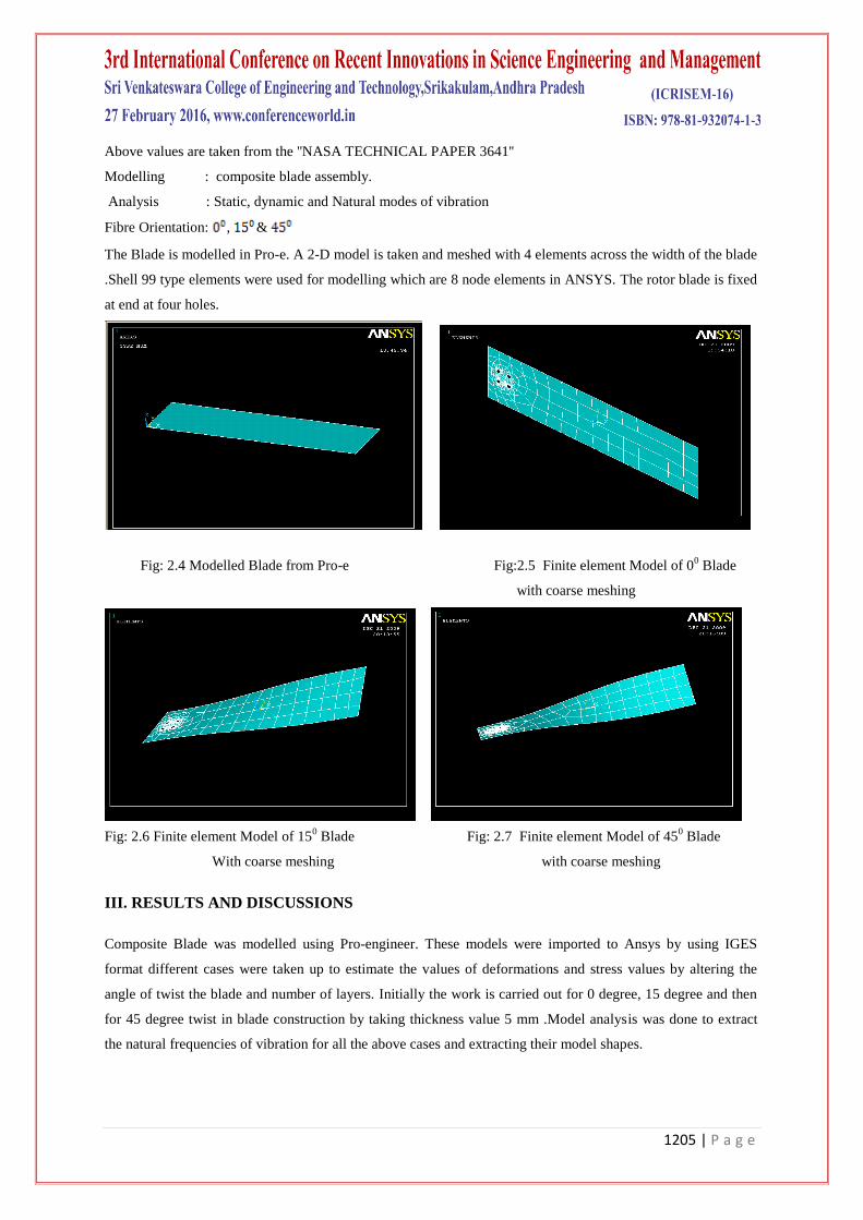
The Blade is modelled in Pro-e. A 2-D model is taken and meshed with 4 elements across the width of the blade
.Shell 99 type elements were used for modelling which are 8 node elements in ANSYS. The rotor blade is fixed
at end at four holes.
Fig: 2.4 Modelled Blade from Pro-e Fig:2.5 Finite element Model of 00 Blade
with coarse meshing
Fig: 2.6 Finite element Model of 150 Blade Fig: 2.7 Finite element Model of 45
0 Blade
With coarse meshing with coarse meshing
III. RESULTS AND DISCUSSIONS
Composite Blade was modelled using Pro-engineer. These models were imported to Ansys by using IGES
format different cases were taken up to estimate the values of deformations and stress values by altering the
angle of twist the blade and number of layers. Initially the work is carried out for 0 degree, 15 degree and then
for 45 degree twist in blade construction by taking thickness value 5 mm .Model analysis was done to extract
the natural frequencies of vibration for all the above cases and extracting their model shapes.
1206 | P a g e
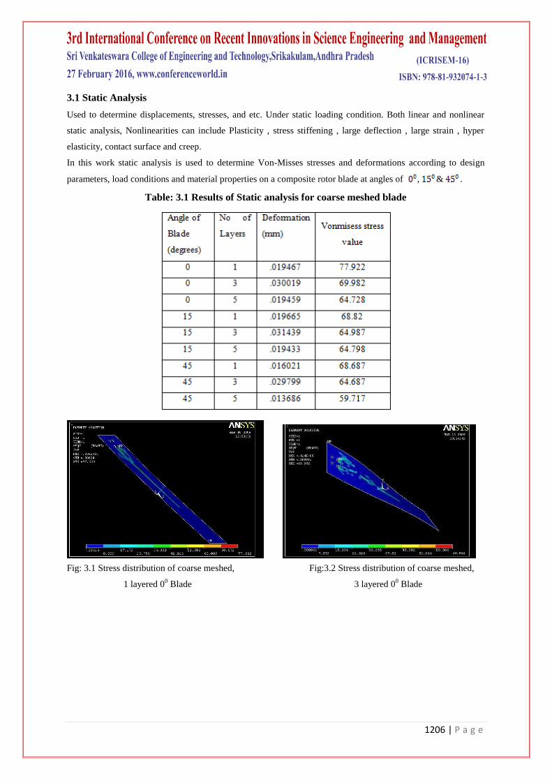
3.1 Static Analysis
Used to determine displacements, stresses, and etc. Under static loading condition. Both linear and nonlinear
static analysis, Nonlinearities can include Plasticity , stress stiffening , large deflection , large strain , hyper
elasticity, contact surface and creep.
In this work static analysis is used to determine Von-Misses stresses and deformations according to design
parameters, load conditions and material properties on a composite rotor blade at angles of , & .
Table: 3.1 Results of Static analysis for coarse meshed blade
Fig: 3.1 Stress distribution of coarse meshed, Fig:3.2 Stress distribution of coarse meshed,
1 layered 00 Blade 3 layered 0
0 Blade
1207 | P a g e
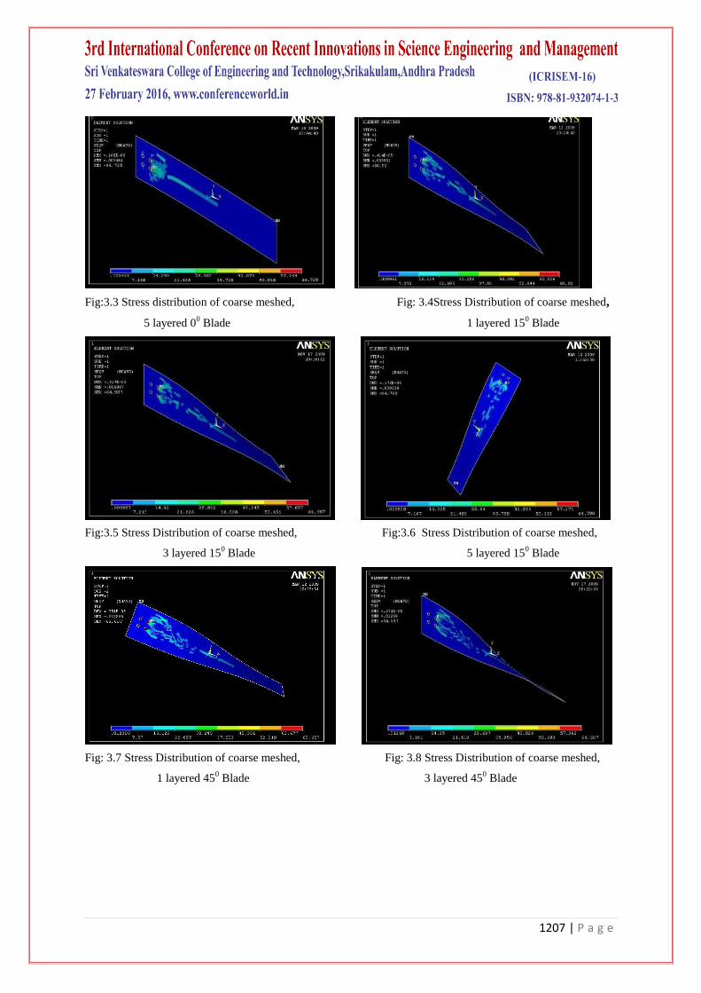
Fig:3.3 Stress distribution of coarse meshed, Fig: 3.4Stress Distribution of coarse meshed,
5 layered 00 Blade 1 layered 15
0 Blade
Fig:3.5 Stress Distribution of coarse meshed, Fig:3.6 Stress Distribution of coarse meshed,
3 layered 150 Blade 5 layered 15
0 Blade
Fig: 3.7 Stress Distribution of coarse meshed, Fig: 3.8 Stress Distribution of coarse meshed,
1 layered 450 Blade 3 layered 45
0 Blade
1208 | P a g e
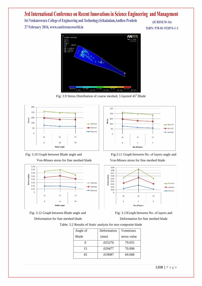
Fig: 3.9 Stress Distribution of coarse meshed, 5 layered 450 Blade
Fig: 3.10 Graph between Blade angle and Fig:3.11 Graph between No. of layers angle and
Von-Misses stress for fine meshed blade Von-Misses stress for fine meshed blade
Fig: 3.12 Graph between Blade angle and Fig: 3.13Graph between No. of layers and
Deformation for fine meshed blade Deformation for fine meshed blade
Table: 3.2 Results of Static analysis for non composite blade
Angle of
Blade
Deformation
(mm)
Vonmisses
stress value
0 .025276 79.055
15 .029477 70.098
45 .019087 69.068
1209 | P a g e
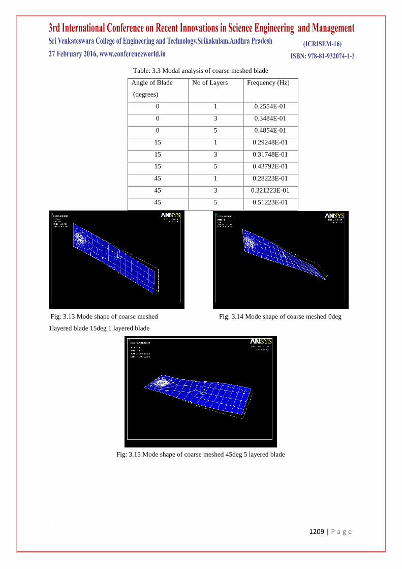
Table: 3.3 Modal analysis of coarse meshed blade
Angle of Blade
(degrees)
No of Layers Frequency (Hz)
0 1 0.2554E-01
0 3 0.3484E-01
0 5 0.4854E-01
15 1 0.29248E-01
15 3 0.31748E-01
15 5 0.43792E-01
45 1 0.28223E-01
45 3 0.321223E-01
45 5 0.51223E-01
Fig: 3.13 Mode shape of coarse meshed Fig: 3.14 Mode shape of coarse meshed 0deg
1layered blade 15deg 1 layered blade
Fig: 3.15 Mode shape of coarse meshed 45deg 5 layered blade
1210 | P a g e
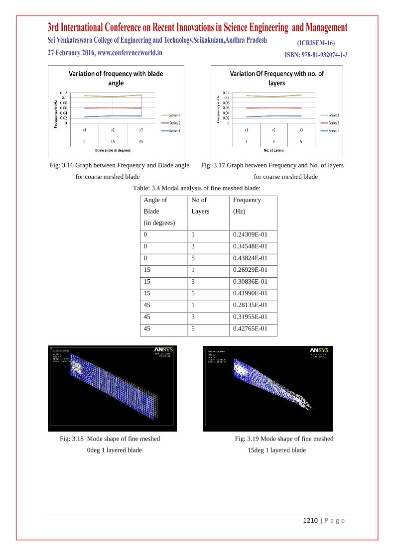
Fig: 3.16 Graph between Frequency and Blade angle Fig: 3.17 Graph between Frequency and No. of layers
for coarse meshed blade for coarse meshed blade
Table: 3.4 Modal analysis of fine meshed blade:
Angle of
Blade
(in degrees)
No of
Layers
Frequency
(Hz)
0 1 0.24309E-01
0 3 0.34548E-01
0 5 0.43824E-01
15 1 0.26929E-01
15 3 0.30836E-01
15 5 0.41990E-01
45 1 0.28135E-01
45 3 0.31955E-01
45 5 0.42765E-01
Fig: 3.18 Mode shape of fine meshed Fig: 3.19 Mode shape of fine meshed
0deg 1 layered blade 15deg 1 layered blade
1211 | P a g e
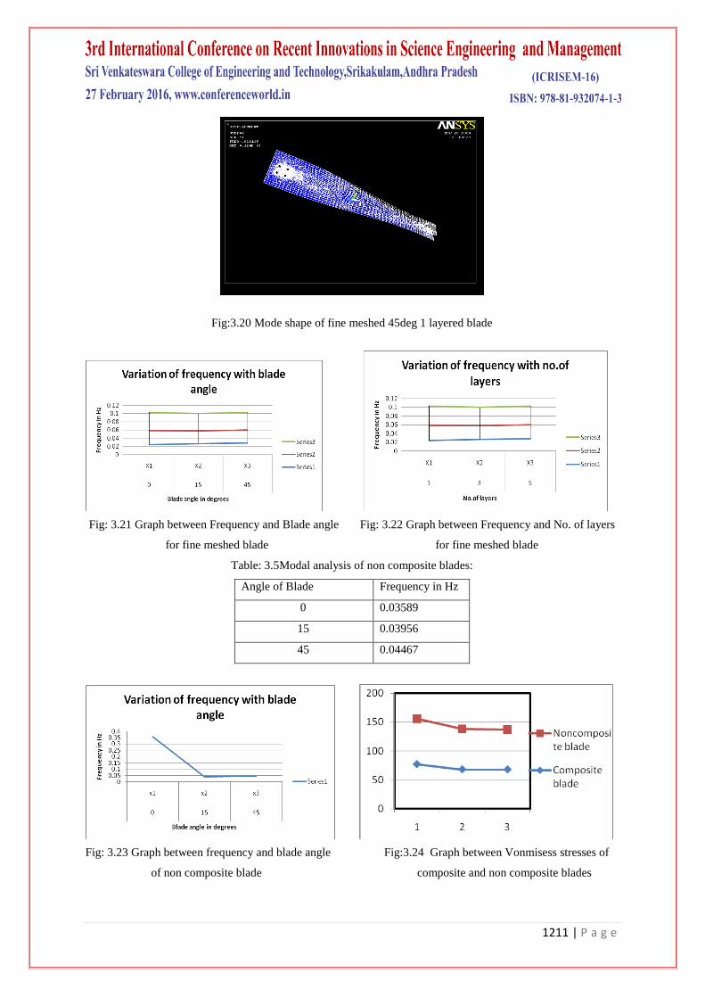
Fig:3.20 Mode shape of fine meshed 45deg 1 layered blade
Fig: 3.21 Graph between Frequency and Blade angle Fig: 3.22 Graph between Frequency and No. of layers
for fine meshed blade for fine meshed blade
Table: 3.5Modal analysis of non composite blades:
Angle of Blade Frequency in Hz
0 0.03589
15 0.03956
45 0.04467
Fig: 3.23 Graph between frequency and blade angle Fig:3.24 Graph between Vonmisess stresses of
of non composite blade composite and non composite blades
1212 | P a g e
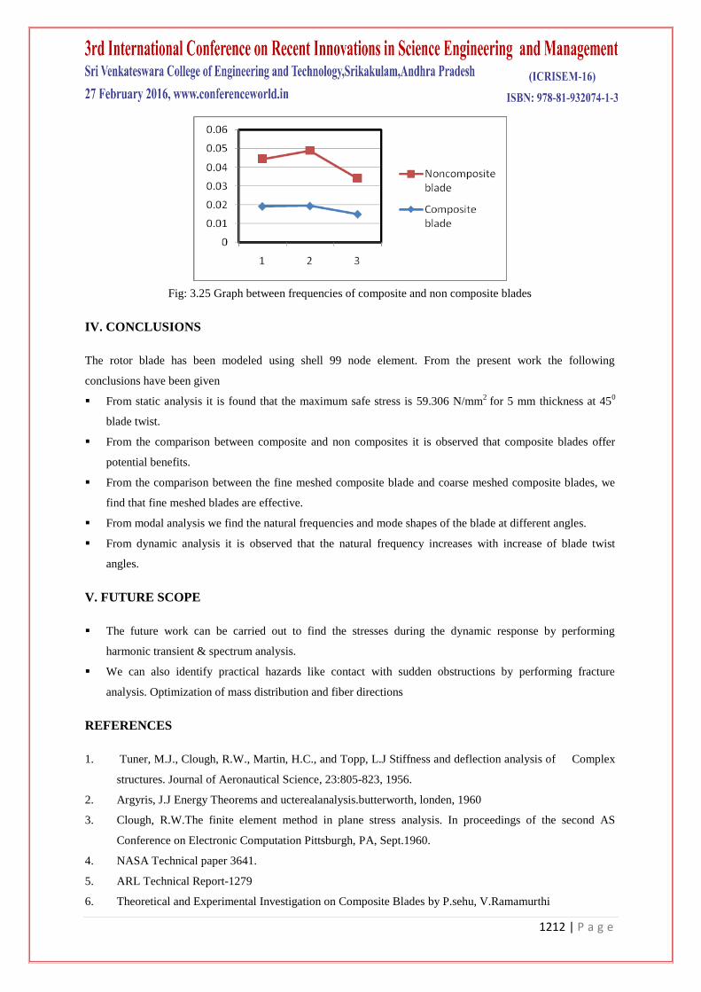
Fig: 3.25 Graph between frequencies of composite and non composite blades
IV. CONCLUSIONS
The rotor blade has been modeled using shell 99 node element. From the present work the following
conclusions have been given
From static analysis it is found that the maximum safe stress is 59.306 N/mm2
for 5 mm thickness at 450
blade twist.
From the comparison between composite and non composites it is observed that composite blades offer
potential benefits.
From the comparison between the fine meshed composite blade and coarse meshed composite blades, we
find that fine meshed blades are effective.
From modal analysis we find the natural frequencies and mode shapes of the blade at different angles.
From dynamic analysis it is observed that the natural frequency increases with increase of blade twist
angles.
V. FUTURE SCOPE
The future work can be carried out to find the stresses during the dynamic response by performing
harmonic transient & spectrum analysis.
We can also identify practical hazards like contact with sudden obstructions by performing fracture
analysis. Optimization of mass distribution and fiber directions
REFERENCES
1. Tuner, M.J., Clough, R.W., Martin, H.C., and Topp, L.J Stiffness and deflection analysis of Complex
structures. Journal of Aeronautical Science, 23:805-823, 1956.
2. Argyris, J.J Energy Theorems and ucterealanalysis.butterworth, londen, 1960
3. Clough, R.W.The finite element method in plane stress analysis. In proceedings of the second AS
Conference on Electronic Computation Pittsburgh, PA, Sept.1960.
4. NASA Technical paper 3641.
5. ARL Technical Report-1279
6. Theoretical and Experimental Investigation on Composite Blades by P.sehu, V.Ramamurthi

1213 | P a g e
7. Chua, K.H Rahman, M.Mansur M.A "'Performance evaluation of machine tool structure using Modal
analysis ", journal of sound and vibration 2(1), pp43-49, Jan 1987.
8. Robert D.cook,''Concepts and applications of finite element analysis'' John Wiley & sons, 2002.
9. S.S.Rao,'' Finite element methods in engineering ", Butter worth Heinemann, 2001.
10. Jones, Robert M.: Mechanics of composite Materials .Scripta Book Co., 1975.
11. Panda, Brahmananda; and chopra, Inderjit: Dynamics of Composite Rotor in Forward Flight.Vertica,
vol.11,no.1/2,1987,pp.187{209.


![Integration of Static and Dynamic Analysis for …arXiv:1912.11249v1 [cs.CR] 24 Dec 2019 Integration of Static and Dynamic Analysis for Malware Family Classification with Composite](https://img.pdfslide.us/doc/110x75/5f3dc54188c8092cfd651c3c/integration-of-static-and-dynamic-analysis-for-arxiv191211249v1-cscr-24-dec.jpg)