Embed Size (px)
Citation preview
Static Analysis to Improve RTL Verification
Akash Agrawal
Thesis submitted to the Faculty of theVirginia Polytechnic Institute and State University
in partial fulfillment of the requirements for the degree of
Master of Sciencein
Computer Engineering
Michael Hsiao, ChairHaibo Zeng
A. Lynn Abbott
February 16, 2017Blacksburg, Virginia
Keywords: Static Analysis, ATPG, RTL, Reachability AnalysisCopyright 2017, Akash Agrawal

Static Analysis to Improve RTL Verification
Akash Agrawal
ABSTRACT
Integrated circuits have traveled a long way from being a general purpose microprocessor to
an application specific circuit. It has become an integral part of the modern era of technology
that we live in. As the applications and their complexities are increasing rapidly every day,
so are the sizes of these circuits. With the increase in the design size, the associated testing
effort to verify these designs is also increased. The goal of this thesis is to leverage some of
the static analysis techniques to reduce the effort of testing and verification at the register
transfer level. Studying a design at register transfer level gives exposure to the relational
information for the design which is inaccessible at the structural level.
In this thesis, we present a way to generate a Data Dependency Graph and a Control Flow
Graph out of a register transfer level description of a circuit description. Next, the generated
graphs are used to perform relation mining to improve the test generation process in terms
of speed, branch coverage and number of test vectors generated. The generated control flow
graph gives valuable information about the flow of information through the circuit design.
We are using this information to create a framework to improve the branch reachability
analysis mainly in terms of the speed. We show the efficiency of our methods by running
them through a suite of ITC’99 benchmark circuits.

Static Analysis to Improve RTL Verification
Akash Agrawal
GENERAL AUDIENCE ABSTRACT
In this era of modern technology, digital circuits and microprocessors have become an un-
avoidable part of everyone’s life. The role of these circuits is becoming more and more critical
as they are running a lot of critical services for us. Testing and verifying the design has been
a very important aspect in the designing of these circuits. With the increasing number of its
applications and the advancement of the technology, the size and complexity of the designs
have also increased. It has imposed a need to test the design at a stage when it is easy to test
and easy to fix also. There have been a lot of research focused on automatically generating
the test pattern at an early stage of development and the work presented in this thesis is an
effort to take it one step further in the process.
The method proposed in this work is taking advantage of the fact that a design speaks for
itself and can give a lot of information if looked at carefully. We present a way to extract
important information about the data dependency and its flow through the design. With
the help of this information, we are generating relations between the design elements which
can aid the test generation process to achieve its goal more efficiently. We are also using
this information to help in proving that some part of the design is inaccessible. We show the
efficiency of our method by running them through benchmark designs.

Dedicated to my family.
Daughter Ishita Agrawal
Wife Varnika Gupta
Parents Ram Prakash and Shusham Agrawal
iv

Acknowledgments
I would first like to thank my advisor Michael Hsiao for his guidance throughout my stint
at Virginia Tech. It was his course and teaching style which motivated me to work towards
a research problem. His belief in my capabilities, encouragement to try new things and the
feedback kept me motivated to produce the ideas presented here.
I would like to thank all the members of PROACTIVE who have supported me directly
or indirectly in my work. Most notably, Kelson Gent and Tonmoy Roy, whose ideas and
contributions were invaluable for my work.
I would like to thank some of my close friends in Blacksburg, Vikas BM, Debjit Gupta,
Ashutosh Agrawal, Rohan Gaur, Ameya Khandekar and Anshuman Verma to make my stay
memorable.
Finally, I would like to thank my wife, Varnika Gupta, for her immense support and love
without which it would not have been possible for me to achieve my goals.
- Akash Agrawal
v
Contents
1 Introduction 1
1.1 Problem Scope . . . . . . . . . . . . . . . . . . . . . . . . . . . . . . . . . . 1
1.2 Contributions of the Thesis . . . . . . . . . . . . . . . . . . . . . . . . . . . 3
1.2.1 Static Analysis . . . . . . . . . . . . . . . . . . . . . . . . . . . . . . 3
1.2.2 Relational Mining . . . . . . . . . . . . . . . . . . . . . . . . . . . . . 4
1.2.3 Improved Reachability Analysis . . . . . . . . . . . . . . . . . . . . . 6
1.3 Thesis Organization . . . . . . . . . . . . . . . . . . . . . . . . . . . . . . . . 7
2 Background 9
2.1 Register Transfer Level Description . . . . . . . . . . . . . . . . . . . . . . . 9
2.2 Verilator . . . . . . . . . . . . . . . . . . . . . . . . . . . . . . . . . . . . . . 12
2.3 Control Flow Graph and Data Flow Graph . . . . . . . . . . . . . . . . . . . 13
2.4 Abstract Syntax Tree . . . . . . . . . . . . . . . . . . . . . . . . . . . . . . . 14
2.5 Branch Coverage . . . . . . . . . . . . . . . . . . . . . . . . . . . . . . . . . 16
vi
2.6 BEACON . . . . . . . . . . . . . . . . . . . . . . . . . . . . . . . . . . . . . 17
2.7 SMT Solver . . . . . . . . . . . . . . . . . . . . . . . . . . . . . . . . . . . . 19
2.7.1 Z3 . . . . . . . . . . . . . . . . . . . . . . . . . . . . . . . . . . . . . 20
2.8 Relations in the Design . . . . . . . . . . . . . . . . . . . . . . . . . . . . . . 21
3 Contributions 22
3.1 Static Analysis . . . . . . . . . . . . . . . . . . . . . . . . . . . . . . . . . . 22
3.1.1 Data Dependency Graph Generation . . . . . . . . . . . . . . . . . . 23
3.1.2 Control Flow Graph Generation . . . . . . . . . . . . . . . . . . . . . 26
3.2 Use of Static Analysis . . . . . . . . . . . . . . . . . . . . . . . . . . . . . . 28
3.2.1 Relation Mining Algorithm . . . . . . . . . . . . . . . . . . . . . . . . 29
3.2.2 Reachability Analysis . . . . . . . . . . . . . . . . . . . . . . . . . . . 32
4 Experimentation and Results 38
4.1 Overview . . . . . . . . . . . . . . . . . . . . . . . . . . . . . . . . . . . . . . 38
4.2 Static Analysis . . . . . . . . . . . . . . . . . . . . . . . . . . . . . . . . . . 39
4.2.1 Experimental Setup . . . . . . . . . . . . . . . . . . . . . . . . . . . . 39
4.2.2 Results . . . . . . . . . . . . . . . . . . . . . . . . . . . . . . . . . . . 40
4.3 Improved BEACON . . . . . . . . . . . . . . . . . . . . . . . . . . . . . . . . 41
4.3.1 Experimental Setup . . . . . . . . . . . . . . . . . . . . . . . . . . . . 41
vii

4.3.2 Results . . . . . . . . . . . . . . . . . . . . . . . . . . . . . . . . . . . 41
4.4 Improved Reachability Analysis . . . . . . . . . . . . . . . . . . . . . . . . . 42
4.4.1 Experimental Setup . . . . . . . . . . . . . . . . . . . . . . . . . . . . 42
4.4.2 Results . . . . . . . . . . . . . . . . . . . . . . . . . . . . . . . . . . . 42
5 Conclusion 45
5.1 Concluding Summary . . . . . . . . . . . . . . . . . . . . . . . . . . . . . . . 45
5.2 Future Work . . . . . . . . . . . . . . . . . . . . . . . . . . . . . . . . . . . . 45
Bibliography 47
viii
List of Figures
2.1 A Simple Synchronous Circuit . . . . . . . . . . . . . . . . . . . . . . . . . . 11
2.2 Verilog description for Figure 2.1 . . . . . . . . . . . . . . . . . . . . . . . . 11
2.3 Sample Verilog code to C++ conversion using Verilator . . . . . . . . . . . . 12
2.4 An example of AST conversion . . . . . . . . . . . . . . . . . . . . . . . . . 15
2.5 A Simple flow for BEACON vector generation . . . . . . . . . . . . . . . . . 18
2.6 BEACON guidance framework . . . . . . . . . . . . . . . . . . . . . . . . . . 19
3.1 An example of DDG for a C++ function . . . . . . . . . . . . . . . . . . . . 23
3.2 An example of DDG for an RTL design . . . . . . . . . . . . . . . . . . . . . 24
3.3 An example of CFG for an RTL design . . . . . . . . . . . . . . . . . . . . . 27
3.4 An example of DDG for an RTL design . . . . . . . . . . . . . . . . . . . . . 31
3.5 Relations generated for Figure 3.4 . . . . . . . . . . . . . . . . . . . . . . . . 31
3.6 Verilated C++ code for Unreachability Analysis . . . . . . . . . . . . . . . . 34
3.7 Assignment Graph for branch 18 in Fig 3.6 . . . . . . . . . . . . . . . . . . . 35
ix

3.8 Inferring Reachability of a Branch Node based on its Children Nodes . . . . 36
x

List of Tables
4.1 OR1200 & ITC99 Core Characteristics . . . . . . . . . . . . . . . . . . . . . 39
4.2 Time taken to generate DDG and CFG . . . . . . . . . . . . . . . . . . . . . 40
4.3 Sequential Stuck-at Fault Coverage Results . . . . . . . . . . . . . . . . . . . 42
4.4 Reachability Analysis Results . . . . . . . . . . . . . . . . . . . . . . . . . . 44
xi

List of Algorithms
3.1 Generating Data Dependency Graph . . . . . . . . . . . . . . . . . . . . . . 25
3.2 Generating Control Flow Graph . . . . . . . . . . . . . . . . . . . . . . . . . 28
3.3 Algorithm for Relation Mining . . . . . . . . . . . . . . . . . . . . . . . . . . 30
3.4 Reachability Analysis Main Function . . . . . . . . . . . . . . . . . . . . . . 33
3.5 Reachability Analysis Recursive Function . . . . . . . . . . . . . . . . . . . . 34
3.6 Reachability Analysis Extension . . . . . . . . . . . . . . . . . . . . . . . . . 37
xii

Chapter 1
Introduction
In this age of technology, integrated circuits have become increasingly important as well as
a critical part of our day to day lives. From our communication to transportation, feeding
to sleeping, they aid us in everything we do. The role of these circuits is becoming more
and more critical every day as they are running a lot of critical things like our cars, health
devices, home security and more. A small glitch in these services is enough to make a big
loss to our lives. With this heavy use, it has become very important to functionally verify
them before putting them in devices for use.
1.1 Problem Scope
Gone are the days when the circuit used to be very small with very simple functionality
[1] so that they can be tested and verified manually. Circuit complexities have increased
rapidly with time. Moore’s [2] law has become a measure of progress for the industry.
This exponential increase in the circuit complexity has immensely increased the testing and
verification efforts.
1

Akash Agrawal Chapter 1. Introduction 2
This increase in circuit size and complexity has imposed a need for new and faster methods
for the formal verification of the design [3]. At present, at least 50% of the chip design time is
spent on verification efforts [4]. As a result, ATPG has become an emerging area of research
interest.
Verification of design needs to be done at each level of the design. The test generation ate
one level can take help from the information available to the previous level. For example,
register transfer level description of design has relational information, valid states of the
signals etc., which is lost at the physical level of design. This high-level information can aid
in the generation of efficient test vectors at lower levels [5].
An approach for verification can be to test all possible input combination for the design and
compare the output for each test against a golden set of expected outputs. This approach
quickly becomes impractical as number of inputs in circuits today can be very large. A
hybrid model was proposed in [6] using a polynomial circuit model to leverage simulation
alongside the use of formal models. Formal verification techniques can check the design
against a spec but its practicality is also limited as no technique till date has not been able
to achieve 100% coverage [7]. There are other simulation-based techniques which work on
evolutionary ants [8, 9, 10], cultural algorithms [11] and ant colony optimization [12].
While most of the techniques use circuit simulation as a way to generate the test vectors,
static analysis can be useful to extract valuable information from the design which can
increase the effectiveness of existing ATPG techniques. In this work, we present a framework
to generate information about the design using static analysis and then further use it to
perform relational mining and an improved branch reachability analysis. The work is able
to generate better test vectors in terms of number of vectors generated, branch coverage

Akash Agrawal Chapter 1. Introduction 3
and time taken to generate them. The reachability analysis is also improved in terms of
efficiency.
1.2 Contributions of the Thesis
The contributions of this thesis can be seen as follows.
1.2.1 Static Analysis
Static analysis is a set of methods which are used to obtain information about the code
structure without executing it. It is also used to obtain an idea about how the information
is going to flow in the program in the form of possible paths through different branch nodes
in the code which is also called data flow analysis. The extent of analysis varies from only
considering the behavior of individual statements and declarations to include the complete
source code of a program. The uses of information obtained by the analysis vary from
highlighting possible coding errors to formal methods that mathematically prove properties
about a given program. Some of the implementation techniques of formal analysis include
[13] abstract interpretation, data flow analysis, symbolic execution etc.
Data flow analysis is performed on the control flow graph of a program. A combination
of control flow graph and data flow analysis has shown to be useful and complementary in
identifying important sections of the program which implements the functionality of a system
[14]. From the control flow graph, a data dependency graph can be generated. The data
dependency graph depicts the dependencies between different variables, inputs, outputs and
constants in the program.

Akash Agrawal Chapter 1. Introduction 4
In RTL descriptions, the behavior of the circuit is often controlled by a state machine which
triggers different behavior for each of the defined states. An easy way of defining a state
machine is through constant assignments. Each of the states is given a unique constant
number. The controlling variable of the state machine will change its value through constant
assignments of these identifiers. “Case” statements in RTL are also worked on constant
assignments most of the times. As hardware works on a per cycle basis, each of these
constant assignments in a given cycle has an effect on the next cycle.
In this work, we propose a way to generate data dependency graph and control flow graph
out of an RTL description of a circuit which can be processed further to extract useful
information about its behavior. It helps to improve the performance of existing methods for
test vector generation and reachability analysis for the branches.
1.2.2 Relational Mining
Due to the growth in circuit complexity, conventional test methodology, such as scan-based
testing, is no longer sufficient to ensure proper post-manufacturing behavior. Complex and
transient defects may require high-quality at-speed tests to adequately cover all defects [15].
To address these issues, functional tests are being used more frequently for testing across the
entire design process [16, 17]. However, high quality functional/sequential automatic test
pattern generation is extremely computationally expensive, particularly for large circuits.
Test patterns that simultaneously provide a high level of coverage for RTL verification and
at-speed coverage stand to yield significant savings in time and monetary costs of test and
verification.

Akash Agrawal Chapter 1. Introduction 5
Gate level sequential ATPG techniques, such as [8], have used swarm intelligence and evo-
lutionary techniques to generate vectors. However, for circuits with deep sequential paths,
the lack of guiding information causes these techniques to fail to generate vectors which ad-
equately exercise the circuit. To gain more accurate information at the RTL [18] represents
the RTL as assignment decision diagrams to utilize formal techniques for test generation.
PACOST [19] uses a formal model to generate an onion-ring guidance model for simulation.
In [20] a data-mining based approach to learn about cross cycle transitions which are used
to guide the test generation towards specific targets. To target the gate level from the RTL,
mixed level generation is used in [21, 22, 5], these methods generate vectors at RTL and then
refine the generation process using gate level simulation or test generation. However, the
invocation of gate-level fault simulation requires the generation of a structural model and the
invocation of gate-level simulation significantly slows these methods restricting the gained
benefit from generation at RTL. Recently, significant advances in RTL state justification
have been made utilizing swarm intelligence and hybrid-stochastic models. BEACON [12],
utilized an evolutionary ant colony optimization to generate functional verification vectors
targeting branch coverage.
In this work, we propose a method to improve the performance of BEACON [12] by adding
static analysis to aid the guidance of the swarm intelligence based test pattern generation
engine. Initially, we convert the circuit from Verilog to a fast, optimized cycle accurate
C++ model using Verilator [23]. While performing this conversion, we also extract a data
dependency graph and a list of single cycle mutually exclusive branches. This information
is further processed to generate a control flow graph for the design and to learn predictable
relationships between cycles. Using this as a feedback the ant colony is able to target sections
Akash Agrawal Chapter 1. Introduction 6
of the code with low levels of excitation and propagation.
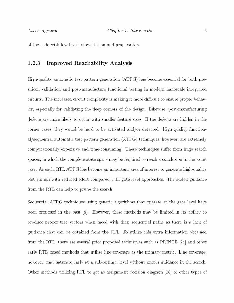
1.2.3 Improved Reachability Analysis
High-quality automatic test pattern generation (ATPG) has become essential for both pre-
silicon validation and post-manufacture functional testing in modern nanoscale integrated
circuits. The increased circuit complexity is making it more difficult to ensure proper behav-
ior, especially for validating the deep corners of the design. Likewise, post-manufacturing
defects are more likely to occur with smaller feature sizes. If the defects are hidden in the
corner cases, they would be hard to be activated and/or detected. High quality function-
al/sequential automatic test pattern generation (ATPG) techniques, however, are extremely
computationally expensive and time-consuming. These techniques suffer from huge search
spaces, in which the complete state space may be required to reach a conclusion in the worst
case. As such, RTL ATPG has become an important area of interest to generate high-quality
test stimuli with reduced effort compared with gate-level approaches. The added guidance
from the RTL can help to prune the search.
Sequential ATPG techniques using genetic algorithms that operate at the gate level have
been proposed in the past [8]. However, these methods may be limited in its ability to
produce proper test vectors when faced with deep sequential paths as there is a lack of
guidance that can be obtained from the RTL. To utilize this extra information obtained
from the RTL, there are several prior proposed techniques such as PRINCE [24] and other
early RTL based methods that utilize line coverage as the primary metric. Line coverage,
however, may saturate early at a sub-optimal level without proper guidance in the search.
Other methods utilizing RTL to get as assignment decision diagram [18] or other types of

Akash Agrawal Chapter 1. Introduction 7
hybrid methods using polynomial circuit model and formal models may fail to reach deep,
narrow states due to the inherent nature of bounded model checking.
In all of these aforementioned methods, determining the reachability of corner cases have
been specifically noted to be a very hard problem as the search space can be very large at
times. One technique that tried to reduce the complexity has been noted in [25]. Instead
of systematically exploring the reachability from the entry point of the design, it follows a
backward search from the target in question. In addition, rather than using a branch-and-
bound search (such as depth-first or breadth-first traversal), it embeds all assignments into
the constraint irrespective of the execution path information and only uses the depth infor-
mation to reduce the complexity. Because no enumeration of paths is performed, significant
speedups have been achieved. However, this method tries to perform reachability analysis
for all the branches and therefore suffers from large run times in large circuits.
In this work, we present a new method of utilizing static analysis to generate both, the control
flow graph and the data flow graph out of the RTL description of a circuit, to determine if a
branch needs to be considered for the reachability analysis or not. Essentially, if a previously
considered branch was found to be reachable, we can prune several related branches, thereby
reducing the effort for unreachability analysis of the whole circuit.
1.3 Thesis Organization
Rest of the thesis is organized as follows.
• Chapter 2 describes the background concepts used in explaining this work.

Akash Agrawal Chapter 1. Introduction 8
• Chapter 3 describes the contributions of this thesis in detail.
• Chapter 4 includes the experimentation’s and their results.
• Chapter 5 concludes the work with a summary of findings and possible future directions
for the research.

Chapter 2
Background
In this chapter, we present the details of RTL representation of circuits along with other
concepts which are used in this work and will be useful to understand it.
2.1 Register Transfer Level Description
In digital circuit design, register transfer level or widely known as RTL is a form of design
abstraction which describes a digital circuit in terms of the signals, registers and logical
operations between them without going into much of the implementation details of these
signals and registers. Hardware description languages like Verilog and VHDL are used in
RTL to create high-level representations of a circuit. Using this high-level description, a
low-level description can be derived which will be converted into actual wiring eventually.
In a synchronous circuit, typically there are two parts, one is combinational and the other is
register. Registers are used to transfer the values from one cycle to another cycle thus making
the circuit synchronous. Transfer of value from one cycle to another typically happens at
a clock edge. Combinational logic is responsible for handling all the logical functionality of
9

Akash Agrawal Chapter 2. Background 10
the design and will be converted into logic gates eventually.
A hardware description language is conceptually similar to any other software languages like
C, C++ etc. The only difference between these two worlds of software and hardware is that
in software everything is sequential whereas in hardware everything is executed in parallel.
This makes a little difference in the languages as well. The hardware language has to handle
the assignments in such a way that in any given cycle, one assignment value should not
affect other assignment values. There are two types of assignments available in HDLs. One
is blocking assignment and the other is non-blocking assignment. In blocking assignments,
an immediate assignment will happen while in non-blocking assignments, the statement will
be evaluated and the value will be assigned at the end of the cycle.
For example, Figure 2.1 shows a simple synchronous circuit diagram. In the circuit, com-
binational part consists of an inverter which inverts the output of the register and feeds it
back to the input after inverting it. The register will trigger this behavior on each positive
edge of the clock.
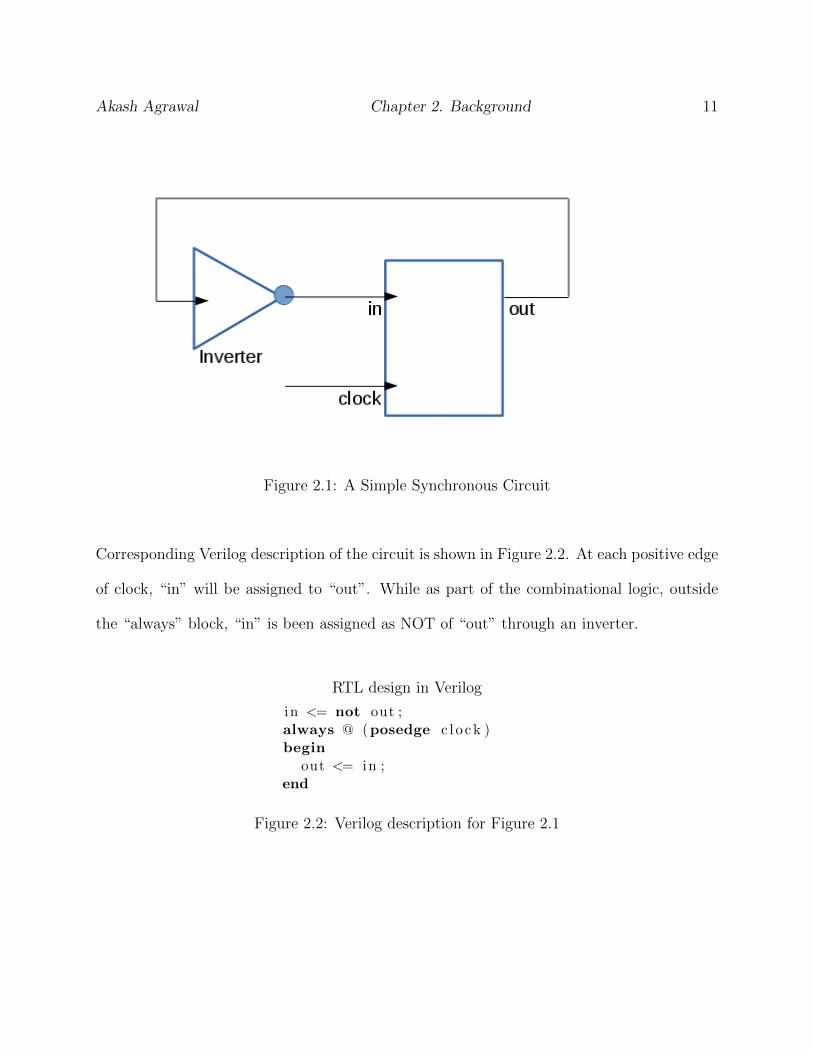
Akash Agrawal Chapter 2. Background 11
Figure 2.1: A Simple Synchronous Circuit
Corresponding Verilog description of the circuit is shown in Figure 2.2. At each positive edge
of clock, “in” will be assigned to “out”. While as part of the combinational logic, outside
the “always” block, “in” is been assigned as NOT of “out” through an inverter.
RTL design in Verilog
in <= not out ;always @ (posedge c l o ck )begin
out <= in ;end
Figure 2.2: Verilog description for Figure 2.1

Akash Agrawal Chapter 2. Background 12
2.2 Verilator
Verilator [23] is a cross compiler which converts a synthesizable Verilog code into a cycle
accurate optimized model written in C++ or SystemC. For this work, we are using it to
convert the Verilog description into a C++ description which is referred by “Verilated C++”
in this thesis. It is also the fastest free Verilog HDL simulator and has been designed for
large projects where fast simulation performance is of primary concern. Figure 2.3 shows an
example of an RTL design and its corresponding Verilated C++ model.
RTL design in Verilog
always @ (posedge c l o ck )begin
i f ( r e s e t == 1 ’ b1 ) beginoutp <= 1 ’ b0 ;
endelse begin
case ( inp )1 ’ b0 : outp <= 1 ’ b1 ;1 ’ b1 : outp <= 1 ’ b0 ;
endcaseend
end
Converted C++ code
void Vtop : : sequent TOP 1(Vtop Syms∗ r e s t r i c t vlSymsp ) {
Vtop∗ vlTOPp = vlSymsp−>TOPp;i f (vlTOPp−>r e s e t ) {++(vlSymsp−> Vcoverage [ 0 ] ) ;vlTOPp−>outp = 0 ;
} else {++(vlSymsp−> Vcoverage [ 3 ] ) ;i f (vlTOP−>inp ) {++(vlSymsp−> Vcoverage [ 2 ] ) ;vlTOPp−>outp = 0 ;
}else {
++(vlSymsp−> Vcoverage [ 1 ] ) ;vlTOPp−>outp = 0 ;
}}
}
Figure 2.3: Sample Verilog code to C++ conversion using Verilator
Other than just converting Verilog into C++, the Verilator also optimizes the code to make it
run faster. Verilator also instruments the code with respect to line coverage, toggle coverage
and signal coverage. For the purpose of this research work, we are using line coverage

Akash Agrawal Chapter 2. Background 13
option from Verilator. With line coverage, Verilator provides a way to track that whether
a block of code has been executed or not, at least once during simulation. A block of code
is decided by the entry and exit points in the form of decision-making statements such as
if-else-if or case statements. All the statements with a single same entry and exit points are
grouped in a single block. Each block is assigned a counter variable in the form of vlSymsp-
> Vcoverage[3] and the same will be incremented using ++(vlSymsp-> Vcoverage[3]);.
Each of the counters is an index in the array of coverage counter initialized to “0”. At the
end of each cycle of simulation, we can read this array to figure out what all blocks were
executed during the current simulation.
Verilator converts all the branches in the Verilog RTL design into a branch of C++ code,
which means that none of the original branches are lost. All different types of branches in-
cluding if-else and case statements are converted into C++ if-else statements in the Verilated
C++ code.
2.3 Control Flow Graph and Data Flow Graph
Many compiler-level optimization and static analysis tools utilize the concept of Control
Flow Graphs (CFG) proposed by Allen [26]. The CFG is represented using a graph G(V, e).
The vertices, V , represent the basic blocks of the code, and the flow of executing between
these basic blocks is represented by the edges e. A basic block in a computer program is a
set of program statements that meet the following conditions:
1. Each block can only be entered via the first statement.
2. Each block may only contain one exit statement that leads to another basic block.

Akash Agrawal Chapter 2. Background 14
3. All statements must execute sequentially within a block.
To form the CFG, the final statements of each block are taken as execution targets and are
used to create the graph edges. Many core analysis of a program like loop optimization and
identifying unreachable program segments can be performed by utilizing this transformation
and formation of the CFG.
Operations that rely on the data assigned to an operand during a prior operation are known
as data dependency. Control dependencies on the other hand are the dominance frontier of
a node in the reverse CFG. This represents the necessary control path required to active a
specific operation. A Data Dependency Graph, DDG, can be generated by conducting data
flow analysis on the CFG of a program. Dependencies between register assignments, control
statements and previously assigned data can be elaborated using DDG. Data dependency
analysis can be used to perform program scheduling, software change impact analysis and
compiler analysis [27, 28, 29].
2.4 Abstract Syntax Tree
In computer science, an abstract syntax tree or just syntax tree is a way to present the
abstract syntactic structure of the source code in the form of a tree. Each of the nodes in
tree denotes a construct occurring in the source code. AST structures are widely used in
compilers [30].
Compilers convert a source code in an AST after parsing it because AST offers many advan-
tages such as
Akash Agrawal Chapter 2. Background 15
1. It stores only abstract form of a syntax omitting all grouping parentheses, semicolon
etc.
2. AST usually contains extra information about the program due to the consecutive
stages of analysis by the compiler.
3. An AST can be easily enhanced or edited with information such as properties and
annotations for every element it contains.
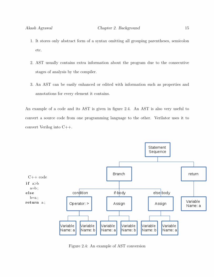
An example of a code and its AST is given in figure 2.4. An AST is also very useful to
convert a source code from one programming language to the other. Verilator uses it to
convert Verilog into C++.
C++ code
i f a>ba=b ;
elseb=a ;
return a ;
Figure 2.4: An example of AST conversion

Akash Agrawal Chapter 2. Background 16
2.5 Branch Coverage
Design validation at the RTL requires a large amount of time and resources. It encompasses
a big chunk of design life cycle of a circuit. A common metric is coverage, or the number of
executed lines, branches etc. of the RTL code [31, 32]. It is used to assess the quality of the
vectors generated using the suggested framework. At 100% branch coverage, we can conclude
that every control state described in the RTL has been visited. A branch is defined as any
decision point involved in the RTL design in the form of if-else statements. Each ‘case’ item
in any ‘switch-case’ statement involved in the design is also considered as a branch point.
A branch point is said to be covered if it is evaluated to ‘true’ at least once by using the
generated input vectors. A higher percentage of branch coverage for a design signifies a
high confidence in the generated vectors as the set ensure sufficient exercise for those many
decision points from the design.
In our work, we have used the open source tool Verilator [23]. This tool is able to convert a
Verilog RTL design into a cycle accurate C++ program. Verilator converts all the branches
in the Verilog RTL design into a branch of C++ code, which means that none of the original
branches are lost. All different types of branches including if-else and case statements are
converted into C++ if-else statements in the Verilated C++ code. Moreover, Verilator
instruments the C++ code by adding a counter at the start of each branch. So when
running the code, the number of times a branch is executed can easily be extracted any time
by reading the value of the corresponding counter.

Akash Agrawal Chapter 2. Background 17
2.6 BEACON
BEACON [12], a Branch-oriented Evolutionary Ant Colony OptimizatioN method is a bio-
inspired meta-heuristic for design validation and functional test generation. It combines
an evolutionary search technique with Ant Colony Optimization [33] for improved search
capability.
There are three steps in the process.
1. Convert RTL description from Verilog to C++ using Verilator and instrument the code
for branch coverage.
2. Generate interface with BEACON.
3. Generated test vectors using BEACON guidance framework.
Conversion from Verilog to C++ has been explained in section 2.2. Once we have the
Verilated C++ description, it is compiled with BEACON to generate a static library which
can simulate the circuit as well as generate test vectors. Figure 2.5 shows a simple flow of
the method.

Akash Agrawal Chapter 2. Background 18
Figure 2.5: A Simple flow for BEACON vector generation
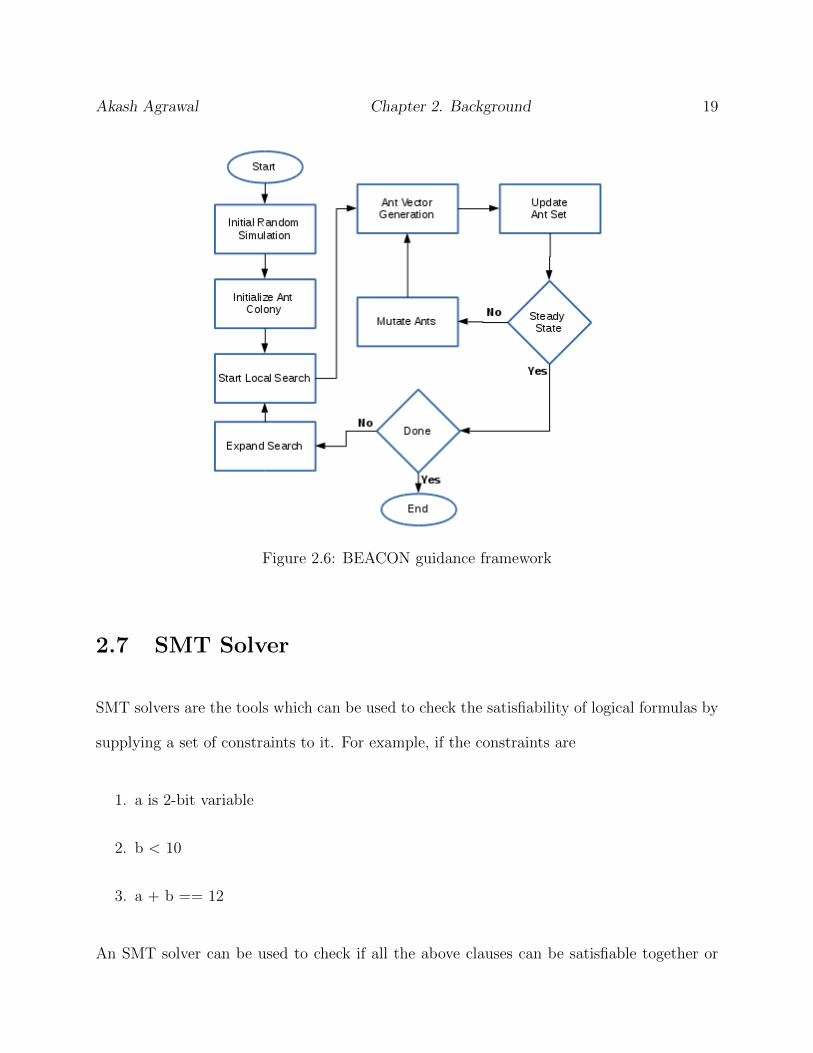
The key part of the whole process is the BEACON guidance framework. It works around an
ant colony which is initialized with a random simulation at the start to get a basic idea of the
circuit. During this initialization, the ant colony will cover most of the easy to reach code
segments. Once the initialization is done, a search will begin again with all the ants. Each
of the ants will do its search and update pheromones on each of the path that is discovered.
Based on this pheromone, it updates the fitness for each of the ants. Again, based on the
fitness, ants with fitness level above than a threshold will go through an evolution phase and
rest of the ants will be dropped. This will be repeated until a steady state is reached. This
will end the local search and all the vectors will be dumped for all the saved ants till now.
Figure 2.6 shows a basic BEACON guidance framework.
Akash Agrawal Chapter 2. Background 19
Figure 2.6: BEACON guidance framework
2.7 SMT Solver
SMT solvers are the tools which can be used to check the satisfiability of logical formulas by
supplying a set of constraints to it. For example, if the constraints are
1. a is 2-bit variable
2. b < 10
3. a + b == 12
An SMT solver can be used to check if all the above clauses can be satisfiable together or

Akash Agrawal Chapter 2. Background 20
not. Each of the clauses will be supplied to the solver as a constraint and it will solve it
to determine its satisfiability. If the instance is satisfiable, then optionally, it can generate
a model also by listing one possible value for each of the variables in the constraints which
can satisfy all the clauses. SMT solvers have been used for test generation in [34, 35].
There is a limitation to SMT solvers. They can handle only boolean expressions, i.e. only
the expressions which can be evaluated to either true or false. Because of this limitation, an
assignment statement will have to be considered as an equality statement while converting
it into a constraint for SMT solver. For example, a=b is supplied as a==b. This conversion
does not modify the fundamental model implied by the assignment.
SMT solvers are of high computational complexity as they draw on the most problems of the
decision diagram, symbolic logic, completeness and incompleteness of logical theories and
complexities. Due to the nature of the problems, their wide scope, it is infeasible to build
an SMT solver which can solve any given set of constraints. It is possible at times that the
solver may not be able to find a solution. In the recent years, a lot of research has gone
into making it more and more robust due to the progress in algorithms, data structures,
heuristics and carefully considering the implementation details [36]. An important driving
factor behind the development of SMT solvers is the annual competition for SAT and SMT
procedures [37].
2.7.1 Z3
In this work, we have used Z3 [38] SMT solver which is an open source software published
by Microsoft Research. It is available with python and C++ implementations. We are using

Akash Agrawal Chapter 2. Background 21
C++ implementation for this work as we are using Verilated C++ description of the RTL.
Z3 imposes a restriction over the format of clauses that can be passed to it for solving a
problem. If a variable is added as part of a constraint, it has to be initialized also in that
constraint. The initialization can be left to Z3 by telling it bit-width of the variable or an
explicit assignment to a constant can also be used to initialize the variable.
2.8 Relations in the Design
There are relations, also known as invariants and implications, which exist in the design.
They can be of various forms, such as (a == 3), (a ¡ b), etc. These relations can be of
immense value to constraining the problem, since they help to steer the search away from
state spaces that violate them. Relations have been used in several other domains as well,
such as post-silicon validation [39], manufacturing test [40, 41, 42], design verification [43, 44],
software testing [45], etc. We will use relations mining in this thesis to help guide the test
generation as well. In addition, when the relations are used as constraints, the test sequences
generated can often be shorter, thereby reducing the cost for a post-process compaction [46].
Chapter 3
Contributions
In this chapter, we present the methods proposed for static analysis in details. Also, it talks
about their applications as well to improve some of the existing methods.
3.1 Static Analysis
In section 1.2.1, we have given a brief introduction to what is static analysis and how it can
be useful for our goal of cutting down on testing/verification efforts for a circuit design. In
this section, we present the framework which will be used for information extraction out of
a design at register transfer level.
In section 3.1.1, we will discuss what is a Data Dependency Graph (DDG), how it is being
represented in this work and the algorithm used to generate the DDG. In section 3.1.2, we
will discuss the details about the Control Flow Graph (CFG).
22
Akash Agrawal Chapter 3. Contributions 23
3.1.1 Data Dependency Graph Generation
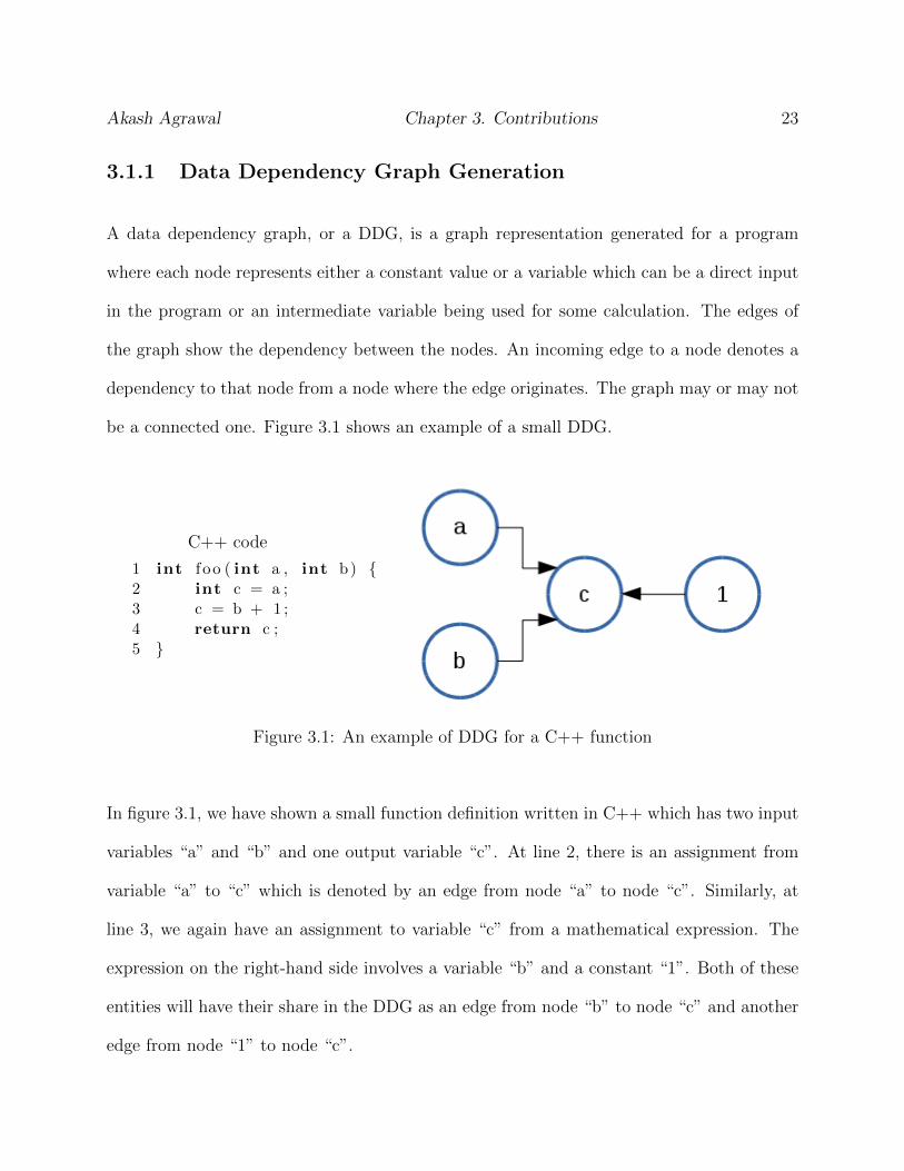
A data dependency graph, or a DDG, is a graph representation generated for a program
where each node represents either a constant value or a variable which can be a direct input
in the program or an intermediate variable being used for some calculation. The edges of
the graph show the dependency between the nodes. An incoming edge to a node denotes a
dependency to that node from a node where the edge originates. The graph may or may not
be a connected one. Figure 3.1 shows an example of a small DDG.
C++ code
1 int f oo ( int a , int b) {2 int c = a ;3 c = b + 1 ;4 return c ;5 }
Figure 3.1: An example of DDG for a C++ function
In figure 3.1, we have shown a small function definition written in C++ which has two input
variables “a” and “b” and one output variable “c”. At line 2, there is an assignment from
variable “a” to “c” which is denoted by an edge from node “a” to node “c”. Similarly, at
line 3, we again have an assignment to variable “c” from a mathematical expression. The
expression on the right-hand side involves a variable “b” and a constant “1”. Both of these
entities will have their share in the DDG as an edge from node “b” to node “c” and another
edge from node “1” to node “c”.

Akash Agrawal Chapter 3. Contributions 24
In this work, we are generating DDG from a given RTL description of a circuit. Also, it
is defined per cycle of execution so that we can have a definite start and end point while
traversing any dependency path. In RTL, we have primary inputs and primary outputs for a
circuit. The way a DDG is defined, it is very easy to identify these nodes in the graph. Any
node with no incoming edge in the graph is either a primary input variable or a constant. All
other nodes in the graph will have at least one incoming edge. Similarly, a primary output
variable node cannot have an outgoing edge. Additionally, we are loading the DDG with
branch path annotations over the edges. The annotations over each edge represent the list of
branches needed to be executed to achieve the dependency denoted by that edge. An edge
can have multiple annotations as multiple paths can exist through which that dependency
can be achieved. Figure 3.2 shows an example of a DDG generated for a small RTL design.
RTL Design basicstyle
1 i f ( s t a r t )2 i n s t p t [0]++;3 s t a to = 10 ;4 else5 i n s t p t [1]++;6 i f ( s t a t o == 10)7 i n s t p t [2]++;8 x <= y ;9 s t a to <= 20 ;
10 else i f ( s t a t o == 20)11 i n s t p t [3]++;12 z <= x ;
Figure 3.2: An example of DDG for an RTL design
In Figure 3.2, for simplicity we have clubbed both the constant into a single node named
“const”. In the code, inst pt[i] denotes the branch point index. A path annotation is made

Akash Agrawal Chapter 3. Contributions 25
up of the branch index separated by a hyphen. Variables “stato” can be assigned from a
constant in two ways and that’s why the edge in DDG has two annotations. It is to be noted
here is that variable “start” is not getting assigned to/from anything and that’s why it is
presented as an individual node in the DDG. Similarly, to achieve the dependency from “y”
to “x”, assignment at line 8, we will have to follow branch “0” followed by branch “2”. Any
other branch path will not help to achieve that dependency. The variable “inst pt” is part
of the instrumented code from Verilator and therefore not present in the generated DDG.
In order to generate DDG, we leverage the AST available through Verilator. It gives all
the information about each and every assignment statement in the design. While traversing
through the AST, we also have access to all branch point indices as Verilator has already
instrumented all the branches by then. While traversing the AST, we keep track of the
current branch. Whenever we reach an assignment statement, we add the node and edge to
the DDG if does not exist already. The details of the method are given in Algorithm 3.1.
Algorithm 3.1 Generating Data Dependency Graph
1: Initialize and read in Verilated C++2: for all assignments do3: Extract involved variables from assignments4: for all variables do5: if node NOT exist then6: create node7: end if8: end for9: Extract branch index10: Add branch to path11: Add edge lhs← rhs to the DDG12: Add path as annotation to the edge13: end for

Akash Agrawal Chapter 3. Contributions 26
3.1.2 Control Flow Graph Generation
A Control Flow Graph, or CFG, for a program is used to show the flow of control during a
program execution. In software, typically, CFG is in the form of a tree as software usually
has a single entry and exit points in the program execution. Opposed to this, in hardware,
an RTL design runs in parallel and thus can have multiple paths going from input to output,
all executing simultaneously. Therefore, CFG for an RTL design is usually a group of trees
instead of being a single tree.
For this work, instead of directly generating a CFG, we are extracting a list of single cycle
mutually exclusive branches. For a design, each entry in this list is a list of branches for which
we can guarantee that only one of them will be executed in any given cycle of execution.
By using this list we can generate all possible control paths in a design. Each entry of the
list also includes all the controlling variables for that entry. A controlling variable can be a
single or a group of variables that needs to be assessed in order to take decision for a branch.
An example of the generated list is given below in Figure 3.3.

Akash Agrawal Chapter 3. Contributions 27
RTL Design
1 i f ( s t a r t )2 i n s t p t [0]++;3 s t a to = 10 ;4 x = 1 ;5 else6 i n s t p t [1]++;7 y = 0 ;8 i f ( s t a t o == 10)9 i n s t p t [2]++;10 s t a to <= 20 ;11 i f ( x == 1)12 i n s t p t [3]++;13 else i f ( y == 0)14 i n s t p t [4]++;
Figure 3.3: An example of CFG for an RTL design
For example, the code in Figure 3.3 is a snippet from a Verilated C++ code. There are five
branches in the example. The corresponding generated list has three entries “-0-1”, “-2” and
“2-3-4”. The first element for each of the entries is its parent node in the CFG. A blank first
element denotes that there is no parent branch for this entry. We can see here that branches
0 and 1 cannot be accessed in a single cycle as they are part of the if-else statement and
there is no parent branch for this set. Similarly branches 3 and 4 also cannot be accessed at
the same time but they have a parent branch which is branch 2 in this case. For the first
set of two branches, variable “start” plays a role of controlling variable. For branch 4, the
controlling variables are “x” and “y” and both of these variables are need to be accessed to
evaluate branch 4. It is to be noted here that variable “stato” will also need to be accessed
to reach branch 4 but that information can be easily extracted from the fact that branch 2
serves as a parent branch for this entry of the CFG.
To generate the CFG for an RTL, we again process it in the AST generated by the Verilator

Akash Agrawal Chapter 3. Contributions 28
while instrumenting the design for branch coverage. While traversing the branches, we keep
track of current branch. If a new branch exists inside the current branch, set the current as
parent for the newly found branch and also update the list of controlling variables for the
branch. The details of the method are given in Algorithm 3.2.
Algorithm 3.2 Generating Control Flow Graph
1: Initialize and read in Verilated C++2: parent = NULL3: for all branches do4: again : Extract involved variables from branch− condition5: if nested− branch exist then6: Set parent7: Add variables to activating list8: goto again9: else10: Add parent to current branch list11: Add sibling − branches to CFG12: Add variables to activating variables13: end if14: end for
3.2 Use of Static Analysis
In this section, we present how we can use the information generated by the static analysis
explained in Section 3.1. For the scope of this thesis, we have shown the effectiveness of
static analysis with the following two ways.
1. Improvements in BEACON by doing relational mining to aid the search.
2. Improvements in the reachability analysis of the branches in RTL.

Akash Agrawal Chapter 3. Contributions 29
3.2.1 Relation Mining Algorithm
Once DDG and CFG are generated for the circuit, they are analyzed further to learn specific
information about the cross-cycle behavior for the circuit under test. There are always some
cycle exclusive paths exist in the circuit. They are formed by the conditional statements like
if-else-if or switch-case statements and they allow only one of those conditional blocks to get
activated in a single cycle. If we look closely, they are mostly the part where a state machine
is being defined in the circuit. Because of this, they offer an opportunity to learn more
about the circuit behavior. Using these paths and the generated DDG, we try to generate
cross-cycle dependencies for the circuit.
Typically, there is always a variable in the RTL which is always being assigned from a
constant value. These type of variable form a state machine and are of the primary target
for our algorithm. With the help of these variables and assignments, the algorithm aims to
predict the branch that is guaranteed to be executed in the next cycle. From the DDG, we
lookup for such variables where all the incoming edges are from “constant” nodes. Once we
get the list of such variables, for each such variable, we apply the value to the dependent
conditional statements in the CFG. If this evaluates to “true” for a branch, we have found a
cross-cycle dependency from the assignment in cycle “i” to the branch in cycle “i+1”. Thus
we establish a dependency between the path for the assignment, necessary constraints to
activate that path and the branch. The details of the method are given in Algorithm 3.3.
Akash Agrawal Chapter 3. Contributions 30
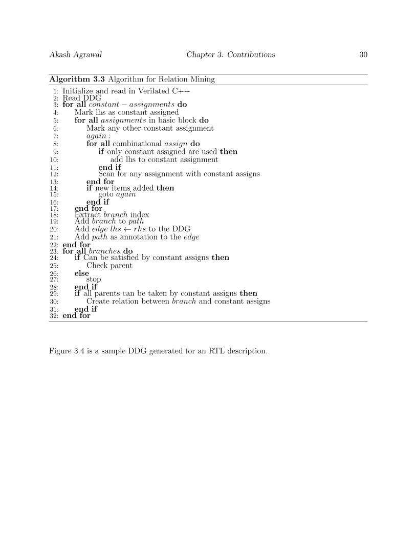
Algorithm 3.3 Algorithm for Relation Mining
1: Initialize and read in Verilated C++2: Read DDG3: for all constant− assignments do4: Mark lhs as constant assigned5: for all assignments in basic block do6: Mark any other constant assignment7: again :8: for all combinational assign do9: if only constant assigned are used then10: add lhs to constant assignment11: end if12: Scan for any assignment with constant assigns13: end for14: if new items added then15: goto again16: end if17: end for18: Extract branch index19: Add branch to path20: Add edge lhs← rhs to the DDG21: Add path as annotation to the edge22: end for23: for all branches do24: if Can be satisfied by constant assigns then25: Check parent26: else27: stop28: end if29: if all parents can be taken by constant assigns then30: Create relation between branch and constant assigns31: end if32: end for
Figure 3.4 is a sample DDG generated for an RTL description.

Akash Agrawal Chapter 3. Contributions 31
RTL Design basicstyle
1 i f ( s t a r t )2 i n s t p t [0]++;3 s t a to = 10 ;4 else5 i n s t p t [1]++;6 i f ( s t a t o == 10)7 i n s t p t [2]++;8 x <= y ;9 s t a to <= 20 ;
10 else i f ( s t a t o == 20)11 i n s t p t [3]++;12 z <= x ;
Figure 3.4: An example of DDG for an RTL design
An example of the relations generated by applying the algorithm to Figure 3.4 are shown in
Figure 3.5.
[0]i ∧ (starti+1 = 0)⇒ [1, 2]i+1
[1, 2]i ∧ (starti+1 = 0)⇒ [1, 3]i+1
[1, 3]i ∧ (starti+1 = 0)⇒ [1, stato = 20]i+1
Figure 3.5: Relations generated for Figure 3.4
During the test vector generation using BEACON, generated DDG along with the relations
are supplied to the ant colony. While searching, each ant starts with a state according to
the relationship derived from static analysis and will try to target the code blocks with low
coverage. At each cycle, the ant will use the prior execution path along with the associated
relations to generate more input test vectors. Then, based on the predicted state from the
last cycle and the relations generated, all possible sub-paths will be analyzed. Each sub-path
Akash Agrawal Chapter 3. Contributions 32
is then graded on the basis of the pheromone levels present along that path. An ant will
prefer a sub-path will lower pheromone levels as that will signify a hard to reach code block.
Once a sub-path is selected, the constraints for that sub-path which can control a primary
input will be applied to the generated inputs. For example, in Figure 3.4 and the relations
in Figure 3.5, if “start” is a primary input, then ant will force it to be “0” is the sub-path
“1-2” or “1-3” have lower pheromone levels. Following this, the ant will simulate the circuit
and continue with the search in the same way until a steady state is reached. This effectively
helps the ant colony to reach code blocks which it was not able to reach previously.
3.2.2 Reachability Analysis
We aim to improve the previous low-cost analysis technique [25] to determine the reachability
of branches in RTL code using the information generated by static analysis.
In the existing method, first, the RTL code is instrumented for branch coverage, where each
basic block is a unique identifier. Each basic block is then used to extract assignments that
are present in those blocks and are labeled with corresponding block identifier. This set of
assignments gives an over-approximation for the relevant signals’ domains. It utilizes all the
activating conditions as well as all the assignments for all variables in these conditions. It
generates an assignment table to reason about all the possible assignment combinations that
can satisfy reaching a certain branch. Effectively, for each signal in the activating condition,
the assignments to the variables in question are added to the assignment graph. These
assignments form the first level of the graph. Next, each assignment added to the graph
is checked for references to other signals. Any new signals found in these references are
added as potential predecessor assignments to the first level assignment effectively creating

Akash Agrawal Chapter 3. Contributions 33
a new graph level. This is continued recursively until either a fixed point is reached or the
depth level limit is reached. This graph creates a representation of the possible assignments
relevant to a target activating condition. Finally, this assignment graph is used to generate a
unique SMT constraint. If the constraint is unsatisfiable, it means that no value assignment
to the relevant variables in question can satisfy the target condition, irrespective of which
execution path is taken. Because it generates only one constraint instead of enumerating
multiple constraints corresponding to various paths, significant speedups can be achieved.
It must be mentioned that, the reachability can be proved only if the assignment is acyclic,
i.e., there is no assignment where the signal updates its own value. The complete detail of
this method is given in Algorithm 3.4 and Algorithm 3.5.
Algorithm 3.4 Reachability Analysis Main Function
1: Initialize and read in Verilated C++2: for all signal do3: group assignments of signal with its branch number4: end for5: for all branch do6: Extract preceding and activating conditions of branch7: sig on decision← signal from branch8: Append activating and preceding conditions to solver9: recursive(sig on decision)10: end for

Akash Agrawal Chapter 3. Contributions 34
Algorithm 3.5 Reachability Analysis Recursive Function
Require: sig to add, New signal to be added in solver1: if sig to add is Input then2: return pathsatisfiable3: end if4: if recursion depth > Max Depth then5: solve6: return solver result7: end if8: for all assignment of sig to add do9: Apply SSA, if needed10: Do bitvector extension, if needed11: add assignment to solver12: solve13: if satisfiable AND new signal s in assignment then14: recursive(s)15: end if16: end for
i f ( y > 3) {++cov [ 9 ] ; // branch 9y = 7 ;i f ( x > 5) {
++cov [ 1 8 ] ; // branch 18x = y ;
}else {
++cov [ 5 ] ; // branch 5}
}else {
++cov [ 1 2 ] ; // branch 12x = 4 ;
}
Figure 3.6: Verilated C++ code for Unreachability Analysis
For example, the code in Figure 3.6 shows a snippet of Verilated C++ code. In this example,
we are considering the reachability for branches 9, 18, 5 and 12. We can see the activating
condition for branch 18 is (x > 5) and it has the variable x in the expression. All the
assignments for this variable are used to build an assignment graph as shown in Figure 3.7.

Akash Agrawal Chapter 3. Contributions 35
From the activating and preceding condition of the branch and the generated assignment
graph, an expression can be generated that can be used as an SMT constraint. In this
example, the SMT solver would return satisfiable for branches 9, 18 and 5. The assignment
constraints y = 7, x = y ∧ y = 7 and x = 4 are the assignments that satisfy these branch
conditions respectively. However, branch 12 will be marked as unreachable since there is no
assignment to the variables that can justify the required condition y ≤ 3. In this cast the
SMT constraint expression for branch 12 would be (y < 3)∧ (y == 7), which is unsatisfiable
and hence branch 12 will be unreachable.
Figure 3.7: Assignment Graph for branch 18 in Fig 3.6
In this work, we extend the existing reachability analysis method explained above. Our
improvements focus toward improving the speed of the analysis without affecting the result.
For this extension we first obtain the CFG of the RTL by applying the methodology described
in Section 3.1. As we already know that the CFG obtained is in the form of a tree. If we
traverse a tree, by the nature of it, a child node is only reachable of we first reach its parent
node. If we look at a tree from the bottom, it can be observed that if the leaf node is
reachable, it instantaneously applies that all branches in that path are reachable. In Figure
3.8, let us consider the reachability of the branches 1, 3 and 4 first, since they are all leaf
nodes of the CFG. In this scenario, it is found that branch 1 is reachable, and hence branch
Akash Agrawal Chapter 3. Contributions 36
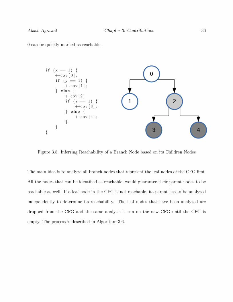
0 can be quickly marked as reachable.
i f ( x == 1) {++cov [ 0 ] ;i f ( y == 1) {
++cov [ 1 ] ;} else {
++cov [ 2 ]i f ( z == 1) {
++cov [ 3 ] ;} else {
++cov [ 4 ] ;}
}}
Figure 3.8: Inferring Reachability of a Branch Node based on its Children Nodes
The main idea is to analyze all branch nodes that represent the leaf nodes of the CFG first.
All the nodes that can be identified as reachable, would guarantee their parent nodes to be
reachable as well. If a leaf node in the CFG is not reachable, its parent has to be analyzed
independently to determine its reachability. The leaf nodes that have been analyzed are
dropped from the CFG and the same analysis is run on the new CFG until the CFG is
empty. The process is described in Algorithm 3.6.

Akash Agrawal Chapter 3. Contributions 37
Algorithm 3.6 Reachability Analysis Extension
Require: G, Control Flow Graph of the HDL design1: while G not Empty do2: for all leaf node, g ε G do3: if check reachable(g) OR reachable[g] then4: reachable[g]← >5: reachable[parent(g)]← >6: end if7: remove(G, g)8: end for9: end while
This process allows for performance boost because of the fact that in the majority of the
real circuits, most unreachable branches are the leaf nodes or close to them. Moreover, most
unreachable branches have at least one reachable sibling. As such, in a significant number
of cases it becomes sufficient to analyze only the leaf nodes, after which most of the parent
nodes can be inferred very quickly.
Chapter 4
Experimentation and Results
In this chapter, we present the details of the experimental setup used for this work along
with the results obtained for the static analysis and both the improvements explained in
Chapter 3.
4.1 Overview
The effectiveness of the proposed method is evaluated using the ITC99 benchmarks [47] and
the OR1200 system on a chip (SOC) [48]. The OpenRisc1200 circuit is a highly configurable
RISC microprocessor with a harvard-style architecture. We have configured OR1200 SOC
to include a power management unit, debug unit, tick timer, and programmable interrupt
controller in addition to the central processing unit. Within the OR1200 CPU, we include
support for division, multiplication and multiply-and-accumulate operators, addc and addic
instructions, and the ALU rotate instruction. We also use b10-b15 of the ITC99 benchmarks
to evaluate the algorithm. To prove the efficacy of the algorithm in traversing hard to test
paths we use b12 and b12word. B12word is an input-extended version of the b12 sequencing
38
Akash Agrawal Chapter 4. Experimentation and Results 39
guessing game, introduced in [19] utilizes sixteen buttons of input instead of four to greatly
increase the difficulty of justifying the games winning.
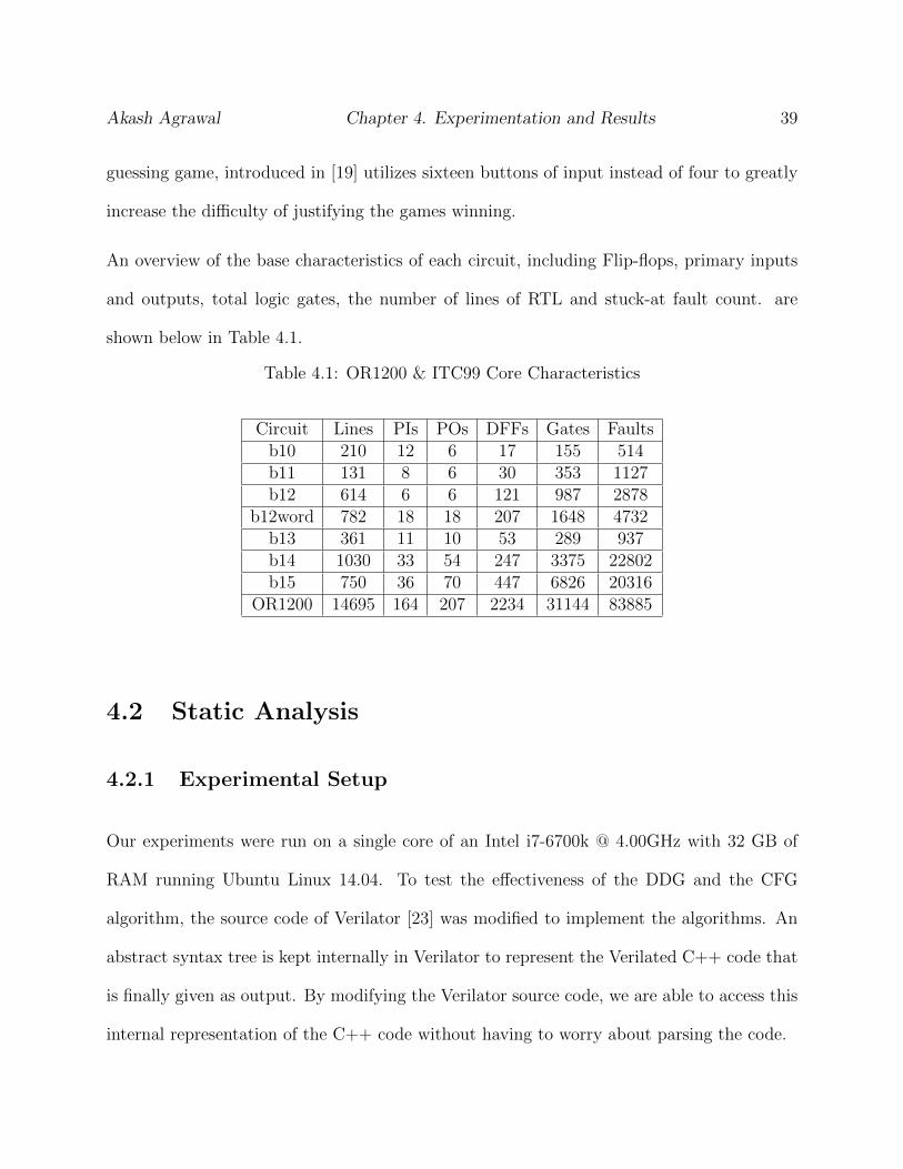
An overview of the base characteristics of each circuit, including Flip-flops, primary inputs
and outputs, total logic gates, the number of lines of RTL and stuck-at fault count. are
shown below in Table 4.1.
Table 4.1: OR1200 & ITC99 Core Characteristics
Circuit Lines PIs POs DFFs Gates Faultsb10 210 12 6 17 155 514b11 131 8 6 30 353 1127b12 614 6 6 121 987 2878
b12word 782 18 18 207 1648 4732b13 361 11 10 53 289 937b14 1030 33 54 247 3375 22802b15 750 36 70 447 6826 20316
OR1200 14695 164 207 2234 31144 83885
4.2 Static Analysis
4.2.1 Experimental Setup
Our experiments were run on a single core of an Intel i7-6700k @ 4.00GHz with 32 GB of
RAM running Ubuntu Linux 14.04. To test the effectiveness of the DDG and the CFG
algorithm, the source code of Verilator [23] was modified to implement the algorithms. An
abstract syntax tree is kept internally in Verilator to represent the Verilated C++ code that
is finally given as output. By modifying the Verilator source code, we are able to access this
internal representation of the C++ code without having to worry about parsing the code.
Akash Agrawal Chapter 4. Experimentation and Results 40
4.2.2 Results
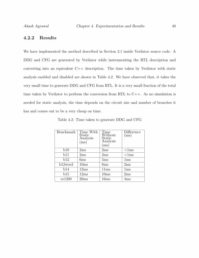
We have implemented the method described in Section 3.1 inside Verilator source code. A
DDG and CFG are generated by Verilator while instrumenting the RTL description and
converting into an equivalent C++ description. The time taken by Verilator with static
analysis enabled and disabled are shown in Table 4.2. We have observed that, it takes the
very small time to generate DDG and CFG from RTL. It is a very small fraction of the total
time taken by Verilator to perform the conversion from RTL to C++. As no simulation is
needed for static analysis, the time depends on the circuit size and number of branches it
has and comes out to be a very cheap on time.
Table 4.2: Time taken to generate DDG and CFG
Benchmark Time WithStaticAnalysis(ms)
TimeWithoutStaticAnalysis(ms)
Difference(ms)
b10 2ms 2ms <1msb11 2ms 2ms <1msb12 6ms 5ms 1ms
b12word 10ms 8ms 2msb14 12ms 11ms 1msb15 12ms 10ms 2ms
or1200 20ms 16ms 4ms

Akash Agrawal Chapter 4. Experimentation and Results 41
4.3 Improved BEACON
4.3.1 Experimental Setup
Our experiments were run on a single core of an Intel i7-6700k @ 4.00GHz with 32 GB of
RAM running Ubuntu Linux 14.04. The ant colony is initialized with K = 100 ants to
allow for a broad search within the colony. The maximum number of iterations is set to
R = 15 and Nsteadystate is set to 5. Pheromones on the code blocks are initialized to 0 and
the maximum amount of pheromones that can be dropped for detected points is Qd = 100,
potentially detected points release a maximum of Qpd = 30 and undetected but activated
points release a maximum Qa = 10. The evaporation rates are ρd = 0.05, ρpd = 0.1 and
ρbase = 0.2.
4.3.2 Results
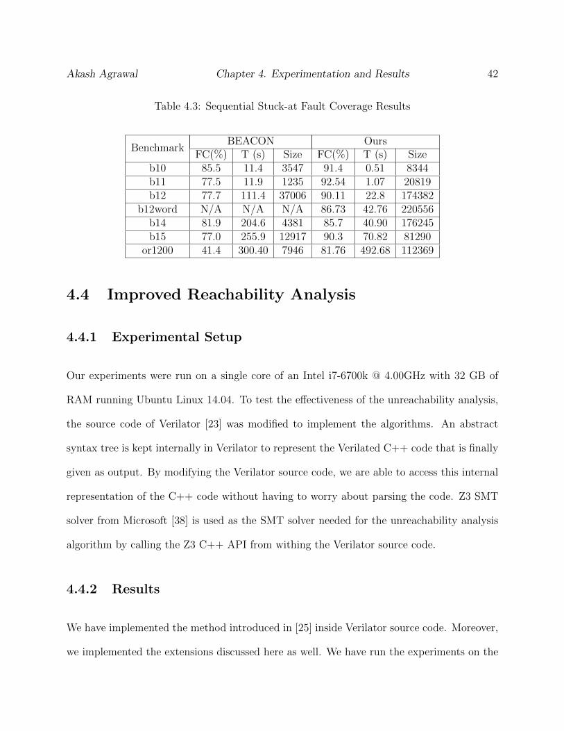
We compare our methodology against prior sequential ATPG algorithms in Table 4.3. Com-
parisons are made against the RTL based ATPG [12]. In order to accurately compare, we
utilize the stuck-at coverage obtained by each method on the benchmark circuits. This high
level of coverage is obtained as more than 10x faster than the time required for gate-level
ATPG. Finally, our method is able to provide high-quality coverage in the presence of hard
to justify paths such as b12 and b12word. For example, in circuit b12, BEACON obtained
77.7% in 111 seconds, and our work achieved 90.11% in just 22.8 seconds.
Akash Agrawal Chapter 4. Experimentation and Results 42
Table 4.3: Sequential Stuck-at Fault Coverage Results
BenchmarkBEACON Ours
FC(%) T (s) Size FC(%) T (s) Sizeb10 85.5 11.4 3547 91.4 0.51 8344b11 77.5 11.9 1235 92.54 1.07 20819b12 77.7 111.4 37006 90.11 22.8 174382
b12word N/A N/A N/A 86.73 42.76 220556b14 81.9 204.6 4381 85.7 40.90 176245b15 77.0 255.9 12917 90.3 70.82 81290
or1200 41.4 300.40 7946 81.76 492.68 112369
4.4 Improved Reachability Analysis
4.4.1 Experimental Setup
Our experiments were run on a single core of an Intel i7-6700k @ 4.00GHz with 32 GB of
RAM running Ubuntu Linux 14.04. To test the effectiveness of the unreachability analysis,
the source code of Verilator [23] was modified to implement the algorithms. An abstract
syntax tree is kept internally in Verilator to represent the Verilated C++ code that is finally
given as output. By modifying the Verilator source code, we are able to access this internal
representation of the C++ code without having to worry about parsing the code. Z3 SMT
solver from Microsoft [38] is used as the SMT solver needed for the unreachability analysis
algorithm by calling the Z3 C++ API from withing the Verilator source code.
4.4.2 Results
We have implemented the method introduced in [25] inside Verilator source code. Moreover,
we implemented the extensions discussed here as well. We have run the experiments on the
Akash Agrawal Chapter 4. Experimentation and Results 43
benchmark circuits with both, the extensions enabled and disabled. We have also run the
experiment over FabScalar, which is a configurable out-or-order superscalar RISC processor.
Ckt A is an industry-size circuit containing more thn 25,000 branches. The cost of construct-
ing the CFG and DDG are included in the results as well. We have observed an average
speedup of 1.5× on the ITC99 circuits with our extension. On a larger circuit like the open
RISC processor, we have observed a speedup of 4.85× using our method. On the bigger
circuits like FabScalar and Ckt A, the speedup is even higher. The detailed timing data is
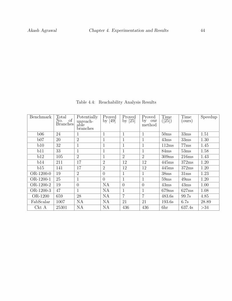
given in Table 4.4. For example, consider ITC99 benchmark circuit b14. From Table 4.4,
we can see that there are a total of 211 branches in the design out of which, 17 branches are
potentially unreachable. Method [49] is able to detect only 2 of them. Method [25] is able to
detect 12 of those 17 potentially unreachable branches in 445ms while our method detects
the same number of unreachable branches in 372ms which is 1.2× faster than method [25].
In all of the cases, the number of unreachable branches detected by [25] and our method
remained the same, as shown in Table 4.4.
Akash Agrawal Chapter 4. Experimentation and Results 44
Table 4.4: Reachability Analysis Results
Benchmark TotalNo. ofBranches
Potentiallyunreach-ablebranches
Provedby [49]
Provedby [25]
Provedby ourmethod
Time([25])
Time(ours)
Speedup
b06 24 1 1 1 1 50ms 33ms 1.51b07 20 2 1 1 1 43ms 33ms 1.30b10 32 1 1 1 1 112ms 77ms 1.45b11 33 1 1 1 1 84ms 53ms 1.58b12 105 2 1 2 2 309ms 216ms 1.43b14 211 17 2 12 12 445ms 372ms 1.20b15 141 17 2 12 12 445ms 372ms 1.20
OR-1200-0 19 2 0 1 1 38ms 31ms 1.23OR-1200-1 25 1 0 1 1 59ms 49ms 1.20OR-1200-2 19 0 NA 0 0 43ms 43ms 1.00OR-1200-3 47 1 NA 1 1 679ms 627ms 1.08OR-1200 659 28 NA 7 7 483.6s 99.7s 4.85FabScalar 1007 NA NA 21 21 193.6s 6.7s 28.89
Ckt A 25301 NA NA 436 436 6hr 637.4s >34

Chapter 5
Conclusion
In this chapter we are giving a concluding summary of the work presented in this thesis. We
are also providing a discussion on future directions of this work.
5.1 Concluding Summary
We have presented a method to perform static analysis on RTL description of a given circuit
and uses of the information extracted by the static analysis to further improve the existing
method for test generation and reachability analysis for the branches.
5.2 Future Work
Through this work, we have shown that data dependency graph and control flow graph can
enhance the test generation and branch reachability analysis. However, there is still a lot
of scope for other static analysis techniques available for software which can be applied to
RTL description to achieve even better results. Abstract interpretation, application of Hoare
logic, model checking using static analysis are some of the examples which can be studied
45

Akash Agrawal Chapter 5. Conclusion 46
to see their effect on RTL test generation or other analysis. Using Verilator, we have access
to an AST of the RTL design. Taking this advantage, additional analysis techniques can be
used which can provide more accurately timed input values to further aid the ATPG engines
to generate the test vector with improved efficiency.

Bibliography
[1] The Chip that Jack Built. http://www.ti.com/corp/docs/kilbyctr/jackbuilt.shtml
[2] G. Moore, “Progress in digital integrated electronics”, in Electron Devices Meeting, 1975
International, vol. 21, pp. 11-13, 1975.
[3] P. Patra, “On the cusp of validation wall”, in Design & test of computers, IEEE, vol.
24, pp. 193-196, 2007.
[4] H. Foster, “The 2010 Wilson Research Group Functional Verification Study”, ed, 2011.
[5] K. Gent and M. S. Hsiao, “Dual-Purpose Mixed-Level Test Generation Using Swarm
Intelligence,” in Test Symposium (ATS), 2014 IEEE 23rd Asian, 2014, pp. 230-235.
[6] M. Mirzaei, M. Tabandeh, B. Alizadeh, and Z. Navabi, A new approach for automatic
test pattern generation in register transfer level circuits, in IEEE Design and Test, vol.
30, pp. 49-59, Aug 2013.
[7] L. Kuan-Yu, C. Po-Juei, L. Ang-Feng, J. C. M. Li, M. S. Hsiao and W. Laung-Terng,
“GPU-based timing-aware test generation for small delay defects,” in Test Symposium
(ETS), 2014 19th IEEE European, 2014, pp. 1-2.
47
Akash Agrawal Bibliography 48
[8] M. S. Hsiao, E. M. Rudnick and J. H. Patel, “Sequential circuit test generation using
dynamic state traversal,” in Proceedings. European Design & Test Conference, pp. 22-28,
1997.
[9] M. S. Hsiao, E. M. Rudnick, and J. H. Patel, “Dynamic state traversal for sequential
circuit test generation,” in ACM Transaction Design Automation Electronics Systems,
vol. 5, pp. 548-565, 2000.
[10] D. Krishnaswamy, M. S. Hsiao, V. Saxena, E. M. Rudnick, J. H. Patel, and P. Banerjee,
“Parallel genetic algorithms for simulation-based sequential circuit test generation,” in
VLSI Design, 1997. Proceedings., Tenth International Conference on, pp. 475-481, 1997.
[11] W. Weixin and M. S. Hsiao, “Efficient Design Validation Based on Cultural Algorithms,”
in Design, Automation and Test in Europe, pp. 402-407, 2008.
[12] M. Li, K. Gent and M. S. Hsiao, “Design validation of RTL circuits using evolutionary
swarm intelligence,” in Proceedings International Test Conference, 2012
[13] V. D’Silva, D. Kroening and G. Weissenbacher, “A Survey of Automated Techniques
for Formal Software Verification,” in IEEE Transactions on CAD of Integrated Circuits
and Systems, pp. 1165-1178, Vol. 27, July 2008.
[14] H. Kuang, P. Mader, H. Hu, A. Ghabi, L. Huang, J. Lu, and A. Egyed, “Can method
data dependencies support the assessment of trace-ability between requirements and
source code?”, in Journal of software: evolution of process, vol. 27, pp. 838-866, 2015.
Akash Agrawal Bibliography 49
[15] E. J. McCluskey ans C.-W. Tseng, “Stuck-fault tests vs. actual defects,” in Proceedings
of the 2000 IEEE International Test Conference, ITC’00, (Washington, DC, USA), pp.
336-, IEEE Computer Society, 2000.
[16] L. Lee, L.-C. Wang, P. Parvathala and T. Mak, “On silicon-based speed path identifi-
cation,” in VLSI Test Symposium, 2005. Proceedings, 23rd IEEE, May 2005.
[17] R. McLaughlin, S. Venkataraman and C. Lim, “Automated debug of speed path failures
using functional tests,” in VLSI Test Symposium, 2009. VTS’09. 27th IEEE, May 2009.
[18] L. Zhang, I. Ghosh and M. S. Hsiao, “Efficient sequential ATPG for functional RTL
circuits,” in Proceedings International Test Conference, vol. 30, pp. 290-298, Sept 2003.
[19] Y. Zhou, T. Wang, T. Lv, H. Li and X. Li, “Path constraint solving based test generation
for hard-to-reach states,” in Proceedings Asian Test Symposium, pp. 239-244, Nov 2013.
[20] K. Gent and M. S. Hsiao, “Abstraction-based relation mining for functional test gener-
ation,” in VLSI Test Symposium (VTS), 2015 IEEE 33rd, pp. 1-6, April 2015.
[21] M. R. Krug, M. S. Lubaszewski and M. de S. Moraes, “Improving ATPG fate-level
fault coverage by using test vectors generated from behavioral HDL descriptions,” in
Proceedings VLSI Tech Symposium, pp. 314-319, Oct 2006.
[22] S. Ravi and N. Jha, “Fast test generation for circuits with RTL and gate-level views,”
in International Test Conference, pp. 1068-1077, 2001.
[23] Verilator, http://www.veripool.org/wiki/verilator.
[24] F. Corno, G. Cumani, M. S. Reorda and G. Squillero, “Effective techniques for high-level
ATPG,” in Proceedings 10th Asian Test Symposium, 2001, pp. 225-230, 2001.

Akash Agrawal Bibliography 50
[25] S. Bagri, K. Gent and M. S. Hsiao, “Signal domain based reachability analysis in RTL
circuits,” in 16th International Symposium on Quality Electronic Design, pp. 250-256,
March 2015.
[26] F. E. Allen. Control flow analysis, SIGPLAN Not., 5(7):1-19, July 1970.
[27] J. L. Henessey and D. A. Patterson, Computer Architecture: A Quantitative Approach.
Morgan Kaufmann Publishers Inc., San Francisco, CA, USA, 3rd Edition, 2003.
[28] S. R. Arnold, Software Change Impact Analysis, IEEE Computer Society Press, Los
Alamitos, CA, USA, 1996.
[29] K. Kennedy and J. R. Allen, Optimizing Compilers for Modern Architecture: A
Dependence-based Approach. Morgan Kaufmann Publishers Inc., San Francisco, CA,
USA, 2002.
[30] Wikipedia page on Abstract Syntax Tree.
Available: https://en.wikipedia.org/wiki/Abstract syntax tree
[31] S. Devadas, A. Ghosh, and K. Keutzer, “An observability-based code coverage met-
ric for functional simulation,” in Proceedings International Conference Computer-Aided
Design, pp. 418-425, 1996.
[32] B. Beizer, Software testing techniques (2nd ed.). New York, NY, USA, Van Nostrand
Reinhold Co., 1990.
[33] M. Dorigo, V. Maniezzo, and A. Colorni, “Ant system: Optimization by a colony of
cooperating agents,” in IEEE Tran. Systems, Man, and Cybernetics, vol. 26, pp. 29-41,
Feb 1996.
Akash Agrawal Bibliography 51
[34] S. Prabhu, M. S. Hsiao, L. Lingappan and V. Gangaram, “Test generation for circuits
with embedded memories using SMT,” in Test Symposium (ETS), 2013 18th IEEE
European, 2012, pp. 1-1.
[35] S. Prabhu, M. S. Hsiao, L. Lingappan and V. Gangaram, “A SMT-based diagnostic test
generation method for combinational circuits,” in VLSI Test Symposium (VTS), 2012
IEEE 30th, 2012, pp. 215-220
[36] L. Moura and N. Bjorner, “Satisfiability Modulo Theories: An Appetizer,” in Formal
Methods: Foundations and Applications, V. Marcel, O. Clus and W. Jim, eds., ed:
Springer-Verilog, 2009, pp. 23-36.
[37] C. Barrett, M. Deters, L. Moura, A. Oliveras, and A. Stump, “6 Years of SMT-COMP,”
J. Autom. Reason., vol. 50, pp. 243-277, 2013.
[38] Z3 Home Page. Available: http://z3.codeplex.com/
[39] S. Prabhakar and M. S. Hsiao, “Using non-trivial logic implications for trace buffer-
based silicon debug,” in IEEE Asian Test Symposium, November 2009, pp. 131-136.
[40] X. Liu and M. S. Hsiao, “Constrained ATPG for broadside transition testing,” in IEEE
International Symposium on Defect and Fault Tolerance in VLSI Systems, November
2003, pp. 175-182.
[41] K. Chandrasekar and M. S. Hsiao, “Integration of learning techniques into incremental
satisfiability for efficient path-delay fault test generation,” in IEEE Design Automation
and Test in Europe Conference, March 2005, pp. 1002-1007.

Akash Agrawal Bibliography 52
[42] M. S. Hsiao, “Maximizing impossibilities for untestable fault identification,” in IEEE
Design Automation and Test in Europe Conference, March, 2002, pp. 949-953.
[43] L. Zhang, M. R. Prasad, and M. S. Hsiao, “Incremental deductive and inductive rea-
soning for SAT-based bounded model checking,” in IEEE International Conference on
Computer Aided Design, November 2004, pp. 502-509.
[44] R. Arora and M. S. Hsiao, “Enhancing SAT-based bounded model checking using se-
quential logic implications,” in IEEE VLSI Design Conference, January, 2004, pp. 784-
787.
[45] X. Cheng and M. S. Hsiao, “Simulation-directed invariant mining for software verifi-
cation,” in IEEE Design Automation and Test in Europe Conference, March 2008, pp.
682-687.
[46] M. S. Hsiao, E. M. Rudnick, and J. H. Patel, “Fast static compaction algorithms for
sequential circuit test vectors,” in IEEE Transactions on Computers, vol. 48, no. 3, pp.
311-322, March, 1999.
[47] S. Davidson, “ITC99 benchmark circuits - preliminary results,” in Proceedings Interna-
tional Symposium, Circuits & Systems, p. 1125, 1999.
[48] “OpenRISC web page.” http://www.opencores.org.
[49] K. Gent and M. S. Hsiao, “Functional test generation at the RTL using swarm intelli-
gence and bounded model checking,” In 2013 22nd Asian Test Symposium, pp. 233-238,
Nov 2013.