Embed Size (px)
Citation preview

ldaho National Engineering and Environmental Laboratory
INEEUEXT-2000-00187
Revision 1June 2000
Statement of Work for FY-00 WellDrilling Activities at Test AreaNorth, Waste Area Group 1,Operable Unit 1-07B
BECHTEL BWXT IDAHO , LLC

INEEL/EXT-2000-00187Revision 1
Statement of Work for FY-00 Well Drilling Activities atTest Area North, Waste Area Group 1,
Operable Unit 1-07B
W. L. JolleyJ. M. Bukowski
Published June 2000
Idaho National Engineering and Environmental LaboratoryEnvironmental Restoration Directorate
Idaho Falls, Idaho 83415
Prepared by Bechtel BWXT Idaho, LLCfor the
U.S. Department of EnergyAssistant Secretary for Environmental Management
Under DOE Idaho Operations OfficeContract DE-AC07-991D13727

CONTENTS
ACRONYMS
1. INTRODUCTION 1-1
1.1 Site Location 1-1
1.2 Site Background 1-1
2. SCOPE OF WORK 2-1
2.1 Drilling Sampling and Installation Activities 2-1
2.1.1 TAN-53 2-4
2.1.2 TAN-54, TAN-55, and TAN-56 2-6
2.2 No-Longer Contained-In Determination Sampling and Containment 2-8
2.2.1 Drilling Containment Devices 2-8
2.2.2 Sample Collection 2-8
2.2.3 Coring Containment Devices 2-9
2.3 Well Construction Materials 2-9
2.4 Miscellaneous Drilling information 2-10
2.5 Grouting 2-10
2.6 Well Site Completion 2-11
3. VENDOR DATA AND MISCELLANEOUS SUBCONTRACTOR EQUIPMENT
REQUIREMENTS 3-1
3.1 Vendor Data Submittal 3-1
3.2 Equipment Requirements 3-1
4. WORK TO BE PERFORMED BY THE CONTRACTOR 4-1
5. GOVERNMENT-FURNISHED EQUIPMENT 5-1
5.1 Schedule X 5-1
6. REFERENCES 6-1
iii

FIGURES
1-1. Proposed well locations 1-2
2-1. Conceptual well design for TAN-53. 2-2
2-2. Conceptual well design for TAN-54 and TAN-55. 2-3
2-3. Locked well cap for Wells TAN-54, TAN-55, and TAN-56. 2-8
TABLES
2-1. Well construction summary 2-1
5-1. Government furnished equipment and material. 5-1
iv

ACRONYMS
ASTM American Standards for Testing and Materials
ASTU Air Stripper Treatment Unit
BBWI Bechtel BWXT Idaho, LLC
bls below land surface
CFR Code of Federal Regulations
DCE trans-1,2-dichloroethene
DOT U.S. Department of Transportation
FY fiscal year
INEEL Idaho National Engineering and Environmental Laboratory
LP liquid propane
MCP management control procedure
NFC National Fire Code
NFPA National Fire Protection Association
NLCID no-longer contained-in determination
PCE tetrachloroethene
OU operable unit
SOW statement of work
TAN Test Area North
TCE trichloroethylene
TSF Technical Support Facility
USGS U.S. Geological Survey
VOC volatile organic compound
WRRTF Water Reactor Research Test Facility

Statement of Work for FY-00 Well Drilling Activities atTest Area North, Waste Area Group 1,
Operable Unit 1-07B
1. INTRODUCTION
This statement of work (SOW) identifies required subcontractor services for well installation andcompletion of four wells at Test Area North (TAN), Operable Unit (OU) 1-07B at the Idaho NationalEngineering and Environmental Laboratory (INEEL). The wells are identified as TAN-53, TAN-54,TAN-55, and TAN-56. This work is being performed as part of groundwater remediation activities in the
vicinity of the TAN Technical Support Facility (TSF)-05 Injection Well.
1.1 Site Location
The locations of the proposed wells are shown in Figure 1-1. Well TAN-53 (MZIW) will be
drilled approximately 15 m (50 ft) east of the TAN Fire Station. Well TAN-54 (PNA-3) will be drilled
approximately 229 m (750 ft) south of Highway 33. Well TAN-55 (PNA-5) will be drilled
approximately 46 m (150 ft) south of Highway 33. Well TAN-56 (PNA-1) will be drilled approximately
457 m (1,500 ft) south of the Water Reactor Research Test Facility (WRRTF). Bechtel BWXT Idaho,
LLC, herein known as the Contractor, will identify the precise locations for drilling these wells to the
subcontractor at the pre-bid meeting site walk-down.
1.2 Site Background
The geology beneath TAN is characterized by basalt flows intercalated with sedimentary
interbeds. Basalt flows are highly variable, from dense to highly vesicular and from massive to highly
fractured. Sedimentary interbeds vary in thickness, with a median thickness of about 1.2 m (4 ft),
generally thinner than interbeds found elsewhere on the INEEL. The two main interbeds, P-Q and Q-R,
consist primarily of silt and clay. The P-Q interbed dips to the south such that the depth to the interbed
varies from about 58 m (190 ft) below land surface (bls) near TSF-05, to about 104 m (340 ft) bls at well
TAN-24a. The P-Q interbed is laterally extensive, but not continuous, and is only encountered in about
half of the wells that are drilled to a depth where it would be expected. Depth to the Q-R interbed ranges
from about 137 to 143 m (450 to 470 ft) bls, with a thickness of about 2.6 m (12 ft). The Q-R interbed
appears to be laterally continuous in the area surrounding TAN and effectively confines contaminants
within the aquifer. A more detailed description of the geology, hydrogeology, and groundwater
contamination at TAN is found in the TAN Site Conceptual Model Reports (Sorenson et al. 1996,
Bukowski and Sorenson 1997, and Bukowski et al. 1998).
1-1

e TAN IN-Ninnge Disp. Q.
z TANT --NON-A-001
TAN CH lo
20,000
TAN 20
1,000
TANT-MON-A -002 TAN Orainage.X!p.
TAN--13A
fTAN 14
To CFA
e TAN 3
e IAN
tPrrara 46
AN-17 \'AN-CN- 2 \
17 \s
47 \
.0 ..
,'?V 1
5 IIITAN-54
eTAN-50 \
— —0 800 1600 2400 Feet
Date Drawn: April 05, 2000
TAN-6I'AN -7
/
TAN-5?
OTAN-51
TAN-16
CIN Ola
TAN Drainage Diep. 02
TAN-31TSF' 06
20,000 —
TAN -PB
TAN -1046
TAN 10,YD TAN 11
TAN Ai" TAN -7,
Evanded —
AN-28
TA -040
TAN-0
AN NIA g9AN-1.9
TAN-41:01.TAN 29
--.. TAN:19% agTAN,:ii
TAN saw,,TAN 34 OTAAT-42 tAN-18 — 033NC3-1724
V, 7
/ TAN .1-- -1.000
TAN 4991 TAPI:.9. 8 ''‘, TAN-32
4,1-AN-53
TAN -40
TAN 'MPTAN -36
12FITY
O GIN--05
GIN-02 ATAN-13111V 7 ••-•"ANI1
TAN-614
GIN-030_
LEGEND
Rends andBuildings
Water Table Contotrs (1998)
TCECarentmtian Contours (u,g/L)
• OU I- 07B Monitoring Wells
O Monitoring Wells
00 Observation Wells
Surface Warn' Injection Wells
e Ptoduction Wells
À Injection Wells
• To Be Completed Wells Doting FY- 00
Hotspur ( > 20,0004 g/L ICE)
.1 Medial Zone ( < 20.(100 > 1,000pg/L TUE)I _ Distal Zone ( < 1,0001 4/1., WE)
(lpsujeushanium_plume_maps: new_mon_well 2000- ap_v1)
Figure 1-1. Proposed well locations.
1-2
2. SCOPE OF WORK
The purpose of this SOW is to: (1) define the location and completion of four new wells to bedrilled during fiscal year (FY) 2000, (2) specify the materials, labor, equipment, and supervisionnecessary to perform the tasks outlined herein, and (3) to define performance specifications foracceptable well completion. Drilling activities for this project are scheduled to begin in May 2000.
2.1 Drilling Sampling and Installation Activities
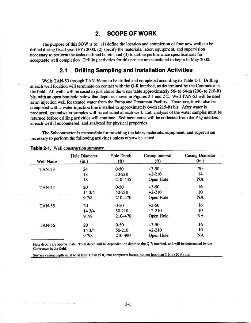
Wells TAN-53 through TAN-56 are to be drilled and completed according to Table 2-1. Drilling
at each well location will terminate on contact with the Q-R interbed, as determined by the Contractor in
the field. All wells will be cased to just above the water table approximately 56- to 64-m (200- to 210-ft)
bls, with an open borehole below that depth as shown in Figures 2-1 and 2-2. Well TAN-53 will be used
as an injection well for treated water from the Pump and Treatment Facility. Therefore, it will also be
completed with a water injection line installed to approximately 64-m (215-ft) bls. After water is
produced, groundwater samples will be collected at each well. Lab analysis of the water samples must be
returned before drilling activities will continue. Sediment cores will be collected from the P-Q interbed
at each well if encountered, and analyzed for physical properties.
The Subcontractor is responsible for providing the labor, materials, equipment, and supervision
necessary to perform the following activities unless otherwise stated.
Table 2-1. Well construction summary.
Well NameHole Diameter
(in.)Hole Depth
(ft)Casing interval
(ft)Casing Diameter
(in.)
TAN-53 24 0-50 +3-50 2018 50-210 +2-210 1418 210-435 Open Hole NA
TAN-54 20 0-50 +3-50 1614 3/4 50-210 +2-210 109 7/8 210-470 Open Hole NA
TAN-55 20 0-50 +3-50 16
14 3/4 50-210 +2-210 109 7/8 210-470 Open Hole NA
TAN-56 20 0-50 +3-50 1614 3/4 50-210 +2-210 109 7/8 210-490 Open Hole NA
Hole depths are approximate. Total depth will be dependent on depth to the Q-R interbed, and will be determined by the
Contractor in the field.
Surface casing depth must be at least 1.5 m (5 ft) into competent basalt, but not less than 5.6 m (20 ft) bls.
2-1

Locking well cap
20" (schedule 40) A53flush thread carbon steel casing
5 ft into competent basaltapprox 50' bls
Surface sediments
Basalt
14" stainless steel (schedule 40) A53flush thread stainless steel casing toapprox 98 ft bis
14" stainless steel type 304wire-wrap screen slot 0.05
from approx 98 to 178 ft bls
Approx 10' grout plug
VWater - 200 ft
Casing interval 20" +3 - 50 ft14" +2 - 198 ft
not to scale
►
►
4
4
Landing plate
Cement pad
24" Borehole to approx 50' bls
4" stainless steel injection lineto approx1220' bls
14" stainless steel (schedule 40) A53flush thread stainless steel casingfrom approx 178 to 198 ft bls
Approx 435' bls
18" Boreholeto top of Q-R interbed
Cem ent grout
Surface sediments*#388:E
Basalt
Bentonite
Q-R lnterbed
Figure 2-1. Conceptual well design for TAN-53.
2-2

16" (schedule 40) A53 flush threadcarbon steel casing 5 ft into
competent basalt approx 50' bls
Surface sediments40:40:00:::::::::-•:::::::-
Basalt
••
Ole"'le
•
10" (schedule 40) flush threadcarbon steel casing to approx 210 ft bls
Water 210 ft
easing Interval 20" +3 - 50 ft14" +2 - 200 ft
not to scale
••••••
Locking well cap
120" Borehole to approx 50' bls
•••
000:0:0:0:
v.41 f,11 P*
*,• • ' 11
14 3/4" Borehole toapprox 210' bls
1-----Approx 10' grout plug
P-Q lnterbed
9 7/8" Borehole to top ofQ-R interbed
Cement rout
Surface sediments*TWA
BasaltPt1W407.1
Bentonite
Q-R lnterbed
Figure 2-2. Conceptual well design for TAN-54, TAN-55, and TAN-56.
2-3
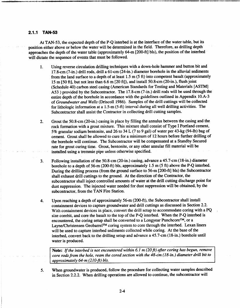
2.1.1 TAN-53
At TAN-53, the expected depth of the P-Q interbed is at the interface of the water table, but its
position either above or below the water will be determined in the field. Therefore, as drilling depth
approaches the depth of the water table (approximately 64-m [200-ft] bls), the position of the interbed
will dictate the sequence of events that must be followed.
1. Using reverse circulation drilling techniques with a down-hole hammer and button bit and
17.8-cm (7-in.) drill rods, drill a 61-cm (24-in.) diameter borehole in the alluvial sediments
from the land surface to a depth of at least 1.5 m (5 ft) into competent basalt (approximately
15 m [50 ft], but not less than 6.6 m [20 ft]), and install 50.8-cm (20-in.), flush joint
(Schedule 40) carbon steel casing (American Standards for Testing and Materials [ASTM]
A53 ) provided by the Subcontractor. The 17.8-cm (7-in.) drill rods will be used through theentire depth of the borehole in accordance with the guidelines outlined in Appendix 10.A-3
of Groundwater and Wells (Driscoll 1986). Samples of the drill cuttings will be collected
for lithologic information at a 1.5-m (5-ft) interval during all well drilling activities. The
Subcontractor shall assist the Contractor in collecting drill cutting samples.
2. Grout the 50.8-cm (20-in.) casing in place by filling the annulus between the casing and the
rock formation with a grout mixture. This mixture shall consist of Type I Portland cement,
5% granular sodium bentonite, and 26 to 34 L (7 to 9 gal) of water per 43-kg (94-lb) bag ofcement. Grout shall be allowed to cure for a minimum of 12 hours before further drilling of
the borehole will continue. The Subcontractor will be compensated at a Standby Secured
rate for grout curing time. Grout, bentonite, or any other annular fill material will be
installed using a tremmie pipe unless otherwise specified.
3. Following installation of the 50.8-cm (20-in.) casing, advance a 45.7-cm (18-in.) diameter
borehole to a depth of 56-m (200-ft) bls, approximately 1.5 m (5 ft) above the P-Q interbed.
During the drilling process (from the ground surface to 56-m [200-ft] bls) the Subcontractor
shall exhaust drill cuttings to the ground. At the direction of the Contractor, thesubcontractor shall inject controlled amounts of water at the drill cutting discharge point for
dust suppression. The injected water needed for dust suppression will be obtained, by the
subcontractor, from the TAN Fire Station.
4. Upon reaching a depth of approximately 56-m (200-ft), the Subcontractor shall install
containment devices to capture groundwater and drill cuttings as discussed in Section 2.2.
With containment devices in place, convert the drill setup to accommodate coring with a PQ
size corebit, and core the basalt to the top of the P-Q interbed. When the P-Q interbed isencountered, the coring setup shall be converted to a Longyear PunchcoreTm, or a
Layne/Christensen GeobarrelTM coring system to core through the interbed. Lexan liners
will be used to capture interbed sediments collected while coring. At the base of the
interbed, convert back to the drilling setup and advance a 45.7-cm (18-in.) borehole until
water is produced.
Note: If the interbed is not encountered within 6.1 m (20 ft) after coring has begun, remove
core rods from the hole, ream the cored section with the 48-cm (18-in.) diameter drill bit to
approximately 64-m (210-ft) bls.
5. When groundwater is produced, follow the procedure for collecting water samples described
in Section 2.2.2. When drilling operations are allowed to continue, the subcontractor will
2-4

continue advancing a 45.7-cm (18-in.) diameter borehole to the top of the Q-R interbed(approximately 132.6-m [435-ft] bls) where drilling will cease.
6. After reaching total depth, excess drill cuttings shall be cleaned from the borehole by thesubcontractor. The well shall be developed until drill cuttings and fine sediments areremoved, and water visibly clears, to the Contractors approval. Well cleaning/development
will be accomplished with the drill rig, by blowing air into the hole to lift the cuttings andwater from the borehole. Well bores shall not be over drilled to accommodate excess drillcuttings. The subcontractor will be reimbursed at the Rig Directed rate for all boreholecleaning/development activities.
7. Upon completion of well development activities, geophysical borehole logging will becompleted by the U.S. Geological Survey (USGS). The drill string shall remain in theborehble until logging activities have been completed so that logging tools may be runwithin the drill string. Geophysical logs to be run will include a neutron log, and a gamma-
gamma log. Upon completion of the neutron, and garnma-gamma logging, the drill rods willbe removed from the borehole, and natural gamma, caliper, deviation, and video logs will berun in the open borehole. Logging may take up to 5 hours to complete. The subcontractorwill be compensated for geophysical logging operations at a Working Ready Standby rate.
8. Following completion of geophysical logging, a 35.6-cm (14-in.) stainless steel casing andscreen will be installed through the unsaturated zone as follows:
Flush joint, (Schedule 40) (ASTM A53) casing from 54.3- to 60.4-m (178- to 198-ft)bls, with a grout basket installed near the bottom (approximately 60-m [197-ft] bls)
Flush joint, Type 304 wire wrap screen with 0.05 slot, from 30-m (98-ft) bls to 54.3-m (178 ft) bls
Flush joint, (Schedule 40) (ASTM A53) casing from 0.6-m (2-ft) above ground to 30-m (98-ft) bls.
The purpose of the screen in the unsaturated zone is to provide hydraulic communication
between the formation and water that may mound during subsequent well injection. The
caiing will be welded to a landing plate and hung from the surface casing.
9. Upon completion of the well, the subcontractor shall install a locking well cap on thesurface casing.
10. Boreholes must no deviate more than 3 degrees from the vertical. Any borehole exceeding
the 3-degree deviation will be abandoned in accordance with state requirements andMCP-226. If because of negligence or carelessness on the part of the subcontractor, aborehole has to be abandoned before it is completed to the specification herein, thesubcontractor will not be paid for the abandoned borehole, and all costs associated with wellabandonment will be covered by the subcontractor. The subcontractor will then drill a new
borehole nearby according to the specifications in this SOW.
2.1.2 TAN-54, TAN-55, and TAN-56
1. Using reverse circulation drilling techniques with a downhole hammer, a button bit, and
17.8-cm (7-in.) drill rods, drill a 50.8-cm (20-in.) diameter borehole in the alluvial sediments
2-5

from the land surface to a depth of at least 1.5 m (5 ft) into competent basalt (approximately
15 m [50 ft], but not less than 6.6 m [20 ft]). Then install 40.6-cm (16-in.) flush joint
(SChedule 40) carbon steel casing (ASTM A53) provided by the subcontractor. The
17.8-cm (7-in.) drill rods will be used through the entire depth of the borehole in accordance
with the guidelines outlined in Appendix 10.A-3 of Groundwater and Wells (Driscoll 1986).
Samples of the drill cuttings will be collected for lithologic information at a 1.5-m (5-ft)
interval during all well drilling activities. The subcontractor shall assist the Contractor in
collecting drill cutting samples.
2. Grout the 40.6-cm (16-in.) casing in place by filling the annulus between the casing and the
rock formation with a grout mixture. This mixture shall consist of Type I Portland cement,
5% granular sodium bentonite, and 26 to 34 L (7 to 9 gal) of water per 43-kg (94-1b) bag of
cement. Grout shall be allowed to cure for a minimum of 12 hours before further drilling of
the borehole will continue. The subcontractor will be compensated for grout curing time at
a Standby Secured rate. Grout and any other annular fill material will be installed using a
tremmie pipe, unless otherwise specified.
3. Drill a 37.5-cm (14 3/4-in.) diameter borehole to just above the water table (approximately
64-m [210-ft] bls). During the drilling process (from the ground surface to the water table)
the subcontractor shall exhaust drill cuttings to the ground. At the direction of the
Contractor, the subcontractor shall inject controlled amounts of water at the drill cutting
discharge point for dust suppression. The injected water needed for dust suppression will be
obtained by the subcontractor from the TAN Fire Station.
4. Upon reaching a depth of 64-m (210-ft) bls, the drill string will be tripped from the borehole
to allow for geophysical logging of the borehole by the USGS. Geophysical logs that will
be run include caliper log, natural gamma log, deviation log, and video log. Logging may
take up to 3 hours to complete. The subcontractor will be compensated during geophysical
logging operations at a Working Ready Standby rate.
5. Following logging activities, install 25.4-cm (10-in.) flush joint, (Schedule 40) carbon steel
casing (ASTM A53) provided by the subcontractor. Seal the 25.4-cm (10-in.) steel casing in
place by filling the annulus between the casing and the rock formation with Number 8
sodium bentonite crumbles.
6. Upon drilling to a depth of approximately 64 m (210 ft) bls, the subcontractor shall install
groundwater containment devices described in Section 2.2.1. Following installation of the
containment devices, a 25-cm (9 7/8-in.) diameter borehole shall be advanced until water is
produced. When groundwater is produced, samples will be collected as described in Section
2.2.2, to ensure that no-longer contained-in determination (NLCID) requirements are
satisfied. When drilling operations are allowed to proceed, the subcontractor will continue
advancing a 25-cm (9 7/8-in.) diameter borehole until reaching a target depth, as determined
by the Contractor, approximately 1.5-m (5-ft) above the estimated depth of the P-Q interbed
(approximately 77.7-m [255-ft] bls for TAN-54 and TAN-55 and approximately 112.7-m
[370-ft] bls for TAN-56).
7. Upon reaching the target depth, drilling will cease, and the drilling operation will be
converted to accommodate coring operations using a PQ size corebit. All cuttings and
groundwater generated during the coring process will be diverted to a small holding tank
separate from the frac-tank already in place. In addition to the holding tank, additional
containment devices, discussed in Section 2.2.3, will be installed prior to beginning the
coring process. The basalt immediately above the interbed shall be cored until the top of the
2-6

P-Q interbed is encountered. Because the P-Q interbed is not laterally continuous, it maynot be present in all wells; therefore, basalt coring will cease and drilling will resume if theP-Q interbed is not encountered within 6.1 m (20 ft) of the start depth. When the interbed isencountered, the coring setup shall be converted to a Longyear PunchcoreTm, orLayne/Christensen GeobarrelTM coring system to core through the interbed. Lexan linerswill be used to contain interbed sediments collected while coring. At the base of the P-Qinterbed, coring will cease, and drilling will resume to advance a 25-cm (9 7/8-in.) diameterborehole to the top of the Q-R interbed (approximately 140-m [470-ft] bls for TAN-54 andTAN-55 and approximately 149-m [490-ft] bls for TAN-56). Drilling will cease when thetop of the Q-R interbed is encountered.
8. Upon drilling a 25-cm (9 7/8-in.) diameter borehole to total depth, geophysical borehole
logging may be completed by the USGS. The drill string shall remain in the borehole untillogging activities have been completed so that logging tools may be run within the drillstring. Geophysical logs that will be run include a neutron log, a gamma-ganuna log, anatural gamma log, and a deviation log. Logging may take up to 5 hours to complete. Thesubcontractor will be compensated for geophysical logging at the Working Ready Standbyrate.
9. At the completion of drilling activities, well development will be conducted according to theprocedures specified in Section 2.4 and the miscellaneous drilling information presented inParagraph 4.
10. Upon completion of the well, the subcontractor shall install a locking well cap on thesurface casing as shown in Figure 2-3.
11. Boreholes must not deviate more than 3 degrees from the vertical. Any borehole exceeding
the 3-degree deviation will be abandoned in accordance with state requirements andManagement Control Procedure (MCP)-226 'Well Construction/Well Abandonment." Ifbecause of negligence or carelessness on the part of the subcontractor, a borehole has to beabandoned before it is completed to the specification herein, the subcontractor will not bepaid for the abandoned borehole, and all costs associated with well abandonment will becovered by the subcontractor. The subcontractor will then drill a new borehole nearbyaccording to the specifications in this SOW.
2-7

Welded metal tabsfor lock attachment
Lock
Lifting handle
4-- Wellcap
4----- Surface casing
Figure 2-3. Locked well cap for Wells TAN-54, TAN-55, and TAN-56.
2.2 No-Longer Contained-ln Determination Sampling andContainment
2.2.1 Drilling Containment Devices
Through past operating procedures at TAN, the aquifer beneath TAN was contaminated with
volatile organic compounds (VOCs), trichlorocthylene (TCE), cis and trans-1,2-dichloroethene (DCE),
tetrachloroethene (PCE), and vinyl chloride, and has been classified as F001-listed waste. Because of the
listed waste classification, water samples will be collected by the Contractor to determine the cumulative
concentration of VOCs in the water reaching the surface. Therefore, before encountering the water table
at a depth of approximately 56- to 64-m (200- to 210-ft) bls, the subcontractor shall install devices on the
drill rig that will capture drill cuttings and groundwater and divert it to a holding tank(s) (frac-tank). The
subcontractor shall provide holding tank(s) of adequate size (approximately 22,712 L [6,000 gal]) for
accommodating all drill cuttings and groundwater, and all equipment necessary for moving the tank
between well sites. To minimize soil disturbance, the holding tank shall not be dragged between sites.
The subcontractor shall also furnish and install a temporary containment device at the well head and
diverter devices that will prevent groundwater produced by the drilling operation from reaching the
ground surface.
2.2.2 Sample Collection
When groundwater is produced, the subcontractor shall immediately notify the Contractor.
Borehole penetration will cease, but the subcontractor shall continue producing water into the holding
tank for approximately 10 minutes. After 10 minutes of continuous water production, the Contractor will
collect two water samples for NLCID. Upon collection of the water samples, the subcontractor will shut
down operations and go to a Standby Secured status until notified by the Contractor to resume work
activities. Standby Secured status will remain in effect until sample analysis results are returned. Lab
results will generally be returned within 1 working day, but may require up to 2 days. The Contractor, as
2-8

a result of the sample analysis, may determine that the drilling operation will require the construction of a
drill rig containment pad, to capture leaking groundwater resulting from drilling operations.
Containment pad construction may require 2 to 3 days to complete. The subcontractor will be
compensated for containment pad construction activities at the Standby Secured rate. In addition, the
subcontractor may be required to install plastic sleeves on the air hoses from the well head and the rig top
head. If this should occur, the subcontractor will be directed to remove the drill string from the borehole
and mobilize equipment out of the drilling area. The Rig Directed rate will be paid for removing the drill
string, mobilizing the rig off the borehole, and installing plastic sleeves on the air hoses. Following
removal of the drill string and rig, the subcontractor shall go to a Standby Secured status, while the
Contractor constructs the containment pad. Upon completion of the containment pad, the Contractor will
direct the subcontractor when drilling operations may continue.
Note: All drilling techniques and components (e.g., rate of air flow, drill string assembly) that were used
during the water sampling process must be used and replicated during the subsequent well drilling in the
saturated zone, except while coring. Additional containment requirements, discussed below, will be
necessary during the coring process.
2.2.3 Coring Containment Devices
Because coring activities will not operate under the same air flow conditions as that of drilling
activities, any coring that occurs below the water table, approximately 56- to 64-m (200- to 210-ft) bls,
will require the construction of a core collection area to contain any water and sediment that may come
from the core. The subcontractor shall install plastic sleeves (if not already in place) on the air hoses
from the well head and drill head. All working surfaces (tables and sawhorses) that may contact the core
will be wrapped in plastic to prevent water and sediment from contacting the surface. All work on the
core (cutting samples from the core, capping and sealing the Lexan liners, etc.) will be completed within
the containment area. In addition, the subcontractor shall supply a small holding tank (approximately
1,892 L [500 gal]) (separate from the frac-tank already in place) to contain any water generated during
the coring process. Hoses from the well head and the drill head will be discharged into this tank. The
Contractor will provide means for removing the water from the tank and transporting it to the Air
Stripper Treatment Unit (ASTU) for dispositioning and decontamination of the tank.
2.3 Well Construction Materials
The subcontractor will furnish the following well casing and well completion accessories for each
well as a minimum. The subcontractor shall furnish catalog cuts/product data as vendor data for each of
the following:
• A sufficient quantity of 40.6-cm (16-in.) flush-joint, Type A53 (Schedule 40) carbon steel
casing
• A sufficient quantity of 25.4-cm (10-in.) flush-joint, Type A53 (Schedule 40) carbon steel
casing
• A sufficient quantity of 50.8-cm (20-in.) flush-joint, Type A53 (Schedule 40) carbon steel
casing
• 110 ft of 35.6 cm (14 in) Type 304 (schedule in stainless steel casing)
• 90 ft of 35.6 cm (14 in) Type 304 wire wrap stainless steel screen with 0.05 slot
2-9

Otte 35.6-cm (14-in.) cement basket
• A sufficient quantity of 23-kg (50-1b) bag.s of Number 8 granular sodium bentonite with a
bulk density of at least 36 kg/ft3 (80 lb/fe)
• A sufficient quantity of Type I Portland cement the subcontractor will provide, in 43-kg (94-
lb) bags and/or by premixed cement batches delivered to the site via cement trucks,depending on the quantity required
• A sufficient quantity of flush coupled, rigid-galvanized steel tremie pipe, or equivalent
• Sufficient quantity of Lexan liners to contain PQ size core.
Note: For 25.4-cm (10-in.) carbon steel casing, 6-m (20-ft) sections may be used.However, at least one 3-m (10-ft) section of carbon steel casing should be supplied for eachwell. The 25.4-cm (10-in.) nominal carbon steel well casing must be factory precleaned(steam cleaned).
2.4 Miscellaneous Drilling information
1. The subcontractor shall minimize the area that is disturbed by drilling operations. Traffic to
and from the drill site shall remain on the two-track access road.
2. Drilling mixtures, other than air or air/water, will not be used during drilling of the well.
3. All downhole drilling equipment will be cleaned using a steam cleaner on adecontamination pad that will be provided by the subcontractor prior to initiating anydrilling. All downhole equipment may also be decontaminated at the completion of each
well, and will be decontaminated prior to demobilization from the site as determined by theContractor. The location of the decontamination pad shall be determined by the Contractor.Downhole equipment (drill rods and bits, etc.) will be decontaminated over thesubcontractor installed decontamination pad in order to remove potential contamination.Decontamination activities will proceed in accordance with the procedures described in the
interim decontamination plan for OU 1-07B (INEEL 1999).
4. After reaching total depth, excess drill cuttings shall be cleaned from the borehole by theSubcontractor. The well shall be developed until drill cuttings and fine sediments areremoved, and water visibly clears, to the Contractors approval. Well bores shall not be over
drilled to accommodate excess drill cuttings. The subcontractor will be reimbursed at theRig Directed rate for all borehole cleaning/development activities. Wells shall be completed
in accordance with MCP-226, "Well Construction/Well Abandonment."
2.5 Grouting
1. All grout (supplied by the subcontractor), except abandonment or lost circulation grout,
shall be a grout mixture of Type I cement, 5% granular sodium bentonite, and 26 to 34 L
(7 to 9 gal) of water per 43-kg (94-1b) bag of cement. A maximum of 1:1 ratio of sand or
pea gravel (supplied by the subcontractor) to cement may be added to the grout mixture to
reduce grout loss.
2-10

2. Abandonment and lost circulation grout (supplied by the subcontractor) may consist ofapproximately 50% Type 11 Portland cement; 2% granular bentonite (2% by weight relativeto the dry cement, approximately 0.9-kg [2-lb] of bentonite per 43-kg [94-1b] sack ofcement); and approximately 48% sand. Curing accelerators (e.g., CaC1) may be added.
2.6 Well Site Completion
Well site completion (protective casing, well head, well pad, impingement posts, brass marker)
will be the responsibility of the Contractor. The subcontractor shall be responsible for drill site cleanup.Cleanup activities include, as a minimum, the following: smooth out ruts from drilling activities, smooth
out (aboveground) drill cuttings, removing all drilling equipment and materials from the drill site,removing all related barricades and fencing materials, and restoring the site as it was prior to drilling.
'Note: The Contractor shall be responsible for reseeding the drill site area.
2-11
3. VENDOR DATA AND MISCELLANEOUS SUBCONTRACTOREQUIPMENT REQUIREMENTS
3.1 Vendor Data Submittal
The contractor will require vendor data submittal for approval of the following items:
• Description of dust suppression methods.
• Temporary containment device at the well head, and diverter devices that will prevent
groundwater produced by the drilling operation from reaching the ground surface.
• Well completion accessories (catalog cuts/product data) for each of the following:
Casing
Bentonite
Cement
Tremmie pipe
Cement basket.
• The latest inspection on masts and hoisting tools, load rating charts, and load test
certification (must be within 12 months of drilling start date).
• The manufacturer's specifications and recommendations concerning masts, hoists, and other
equipment.
• Personnel/operator qualifications—each drilling rig shall have one subcontractor employee
onsite with a valid Idaho well driller/supervisors license. In addition, all drill helpers must
have a minimum of 1 year of drill helper experience.
• Rig use history (the last 12 months)—the subcontractor shall furnish certification stating
that either the drilling rigs have not been previously used at a hazardous waste facility or
identifying at which hazardous waste sites they have been used, the hazardous constituents
to which they were exposed, and the decontamination procedures used following completion
of the work.
• Description of drilling techniques for the tasks described in this SOW.
3.2 Equipment Requirements
A short list of subcontractor equipment necessary to perform the tasks discussed in this SOW is
provided in this section, and the INEEL requirements of this equipment (it is not intended to be a
complete list). In addition to these items, the subcontractor is required to furnish all drilling and
maintenance tools, materials, and equipment not herein designated, but normally required for the
3-1

operation of drilling activities that are within this SOW. The subcontractor is responsible for ensuring
that the materials and equipment used are adequate for the actual conditions encountered. All equipment
and materials so described are subject to inspection/rejection by the Contractor. Drill rigs and all down
hole tools shall be free of excess dirt and grease upon arrival at TAN. All tools and equipment shall be
onsite before startup.
1. Reverse Circulation Air Rotary Rig(s)
The rig(s), shall be a top truck mounted rig capable of both reverse circulation andconventional drilling. It must be capable of drilling, coring, and installing/removing allmaterials as described in this SOW. The rig(s) shall be equipped to inject controlledamounts of water during the drilling process. The drill rig shall be equipped with themaximum air filtration system available.
a. The subcontractor shall perform a thorough inspection of the rig prior to mobilizationand prior to use. A verification of documents (i.e., rig inspection records, checklists)for this rig inspection shall be conducted by the Contractor. All deficiencies shall becorrected in accordance with manufacturer specifications, at no cost to theContractor.
b. The subcontractor shall notify the Contractor a minimum of 5 working days prior tomobilization. The Contractor reserves the right to inspect the drilling and supportequipment at the subcontractor's equipment yard prior to mobilization to the drillingsite. If the equipment is located on-Site at the INEEL, a premobilization inspection
shall be performed at the INEEL at the Contractor's discretion. The Contractorreserves the right to reject any equipment not in conformance with the subcontract.
c. Each drilling rig shall have an operator with a valid Idaho well driller's license anddriller supervisor valid in the State of Idaho (to be submitted to Contractor as vendor
data submittal).
d. Impermeable tarps or plastic sheeting (Visquene) shall be placed beneath drilling rigsto catch oil and hydraulic fluid leaks. A new plastic tarp will be used for each drillingsite. The used tarps will be disposed by the subcontractor, unless otherwise specified.
e. The drilling rig shall have a secondary air compressor on hand, capable of generatingthe same air flow as the primary air compressor used during drilling activities.
2. Air Compressors
All compressors must have in-line oil filters appropriately pressure rated to prevent oil fromentering the borehole.
3. Dust Suppression
The subcontractor shall provide diversion systems to collect and carry cuttings, water, and
dust away from the borehole a minimum of 9.14 m (30 ft) (discharge hose, cyclone, andseparator, etc.) The subcontractor is responsible for dust control and shall comply with
Idaho Administrative Procedures Act 16.01.01251 and 1252. The subcontractor will beresponsible for hauling water for dust suppression, as required. The cyclone separator will
3-2
require a support device when discharging onto a tarp and mounting hardware for a holding
tank when discharging into a tank.
4. Drilling Water Containment
The Contractor will notify the subcontractor that contact with the water table is imminent.Upon receipt of this notification, the subcontractor shall provide a containment device at thewell head to capture any water leaking from diverter seals or any other diversion systemcomponent and ensure that the groundwater does not reach the ground surface.
5. Fuel Tanks, Heaters, and Pressure Vessels
Any portable fuel tanks must be vented and labeled appropriately in accordance with theNational Fire Code (NFC). Fuel tanks must be stored according to the National FireProtection Association (NFPA) guidelines.
All liquid propane (LP) gas heaters shall be equipped with a device to regulate and cut offthe flow of gas during use in case of flame, failure, or rupture. All fuel tanks must beappropriately labeled with their contents and comply to applicable U.S. Department of
Transportation (DOT) regulations and 29 Code of Federal Regulations (CPR) 1926.150,
prior to arrival onsite.
All pressure vessels must be code stamped certified and be current.
6. Tool Joint Lubricant
No petroleum-based lubricants are permitted during the drilling or completion operations,including petroleum-based hammer and drill pipe (joint) lubricants. Material safety datasheets must be provided by the subcontractor for all potential lubricants according torequirements of GC-7C.3b.ii. Tool and drill pipe (joint) lubricants must consist of inertconstituents.
7. High Pressure Steam Cleaner
Steam cleaners will be used to decontaminate equipment and material, as necessary, and
will be supplied by the subcontractor.
8. Slow Opening Gate Valves and Hose
Tlie subcontractor shall supply connections for fire hydrant usage. The Contractor shalldetermine the location of hydrants to utilize.
9. Water Truck
Any equipment that is in violation of the manufacturers specifications or regulatoryrequirements will be rejected by the Contractor.
3-3
4. WORK TO BE PERFORMED BY THE CONTRACTOR
The following work will be performed by the Contractor and is specifically excluded from the
subcontractor's SOW:
• Completion of well head and protective casing
Bcirehole logging
• Sampling and analysis of cuttings, drilling water, and construction waste
• Installation of concrete surface pad, posts, and survey marker
• Surveying of well, completion diagram, and final report
• Industrial hygienist and radiological control surveillance
• Drill cutting and groundwater disposal
• Construction of secondary containment pad (if necessary)
• Construction of core collection area
• Installation of cement pad and brass marker.
4-1
5. GOVERNMENT-FURNISHED EQUIPMENT
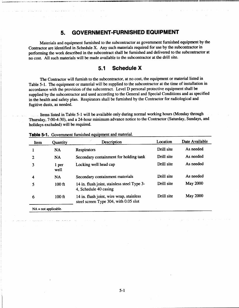
Materials and equipment furnished to the subcontractor as government furnished equipment by the
Contractor are identified in Schedule X. Any such materials required for use by the subcontractor in
performing the work described in the subcontract shall be furnished and delivered to the subcontractor at
no cost. All such materials will be made available to the subcontractor at the drill site.
5.1 Schedule X
The Contractor will furnish to the subcontractor, at no cost, the equipment or material listed in
Table 5-1. The equipment or material will be supplied to the subcontractor at the time of installation in
accordance with the provision of the subcontract. Level D personal protective equipment shall be
supplied by the subcontractor and used according to the General and Special Conditions and as specified
in the health and safety plan. Respirators shall be furnished by the Contractor for radiological and
fugitive dusts, as needed.
Items listed in. Table 5-1 will be available only during normal working hours (Monday through
Thursday, 7:00-4:30), and a 24-hour minimum advance notice to the Contractor (Saturday, Sundays, and
holidays excluded) will be required.
Table 5-1. Government furnished equipment and material.
Item Quantity Description Location Date Available
1 NA Respirators Drill site As needed
2 NA Secondary containment for holding tank Drill site As needed
3 1 perwell
Locking well head cap Drill site As needed
4 NA Secondary containment materials Drill site As needed
5 100 ft 14 in. flush joint, stainless steel Type 3- Drill site May 2000
4, Schedule 40 casing
6 100 ft 14 in. flush joint, wire wrap, stainlesssteel screen Type 304, with 0.05 slot
Drill site May 2000
NA = not applicable.
5-1
6. REFERENCES
Bukowski, J. M., and K. S. Sorenson, Site Conceptual Model: 1996 Activities, Data Analysis, and
Interpretation Test Area North Operable Unit 1-07B, INEEL/EXT-97-00556, Revision O.
Bukowski, J. M., et al., 1998, Site Conceptual Model: 1997 Activities, Data Analysis, and Interpretation
for Test Area North Operable Unit 1-07B, INEEL/EXT-98-00575, Revision O.
Driscoll, F. G., 1986, Groundwater and Wells, Johnsons Filtration Systems Inc., St. Paul, MN,
Appendix 10.A-3, Page 929.
INEEL, 1999, Interim Decontamination Plan for Operable Unit 1-07B, Idaho National Engineering and
Environmental Laboratory, INEEL/EXT-97-01287, Revision 2.
INEEL, MCP-226, "Well Construction/Well Abandonment," Idaho National Engineering and
Environmental Laboratory, current issue.
Sorenson, K. S., A. H. Wylie, and T. R. Wood, 1996, Test Area North Site Conceptual Model and
Proposed Hydrogeologic Studies Operable Unit 1-07B, INEEIJ96-0105, Revision O.
6-1