Embed Size (px)
Citation preview
November 17, 2016
VIA EMAIL AND OVERNIGHT DELIVERY
Ms. Melanie A. Bachman Acting Executive Director
Connecticut Siting Council Ten Franklin Square
New Britain, CT 06051
RE: T-Mobile Northeast LLC – CTFF703A Notice of Exempt Modification
303 Boxwood Lane, Danbury, CT LAT: 41-24-2.15 LNG: 73-26-45.23
Dear Ms. Bachman:
T-Mobile Northeast LLC ("T-Mobile") currently maintains three (3) antennas at a centerline of 83' on the existing 100' lattice tower located at 303 Boxwood Lane, Danbury, CT. The structure is owned by Western Connecticut
State University (“WCSU”); their use of the structure was approved by the Council on October 21, 1996 (Docket No. 176).
Please accept this letter as notification pursuant to Regulations of Connecticut State Agencies 16-50j-73, for construction that constitutes an
exempt modification pursuant to R.C.S.A.16-50j-72(b)(2). In accordance with R.C.S.A. l6-50j-73, a copy of this letter is being sent to Mayor Mark D.
Boughton, City of Danbury and the property owner, the State of Connecticut. The planned modifications to the facility fall squarely within those activities
explicitly provided for in RC.S.A. 16-50j-72(b)(s).
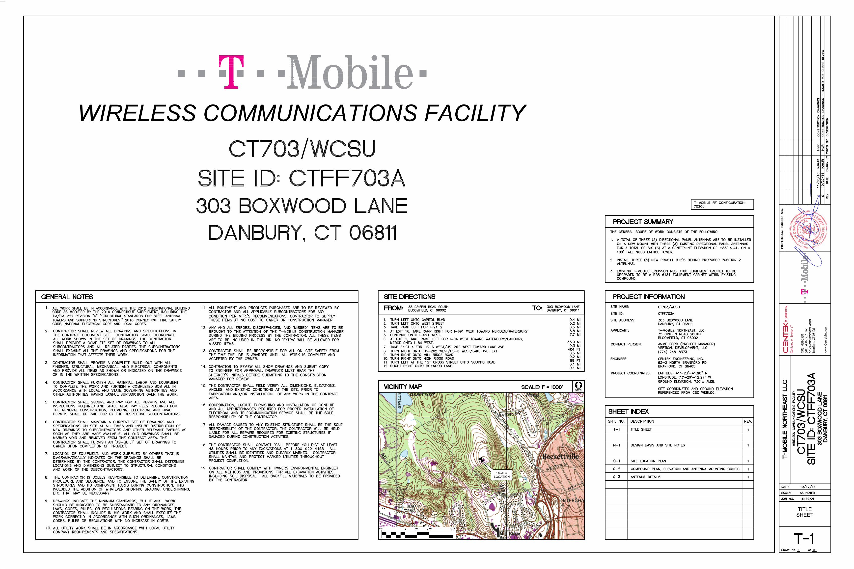
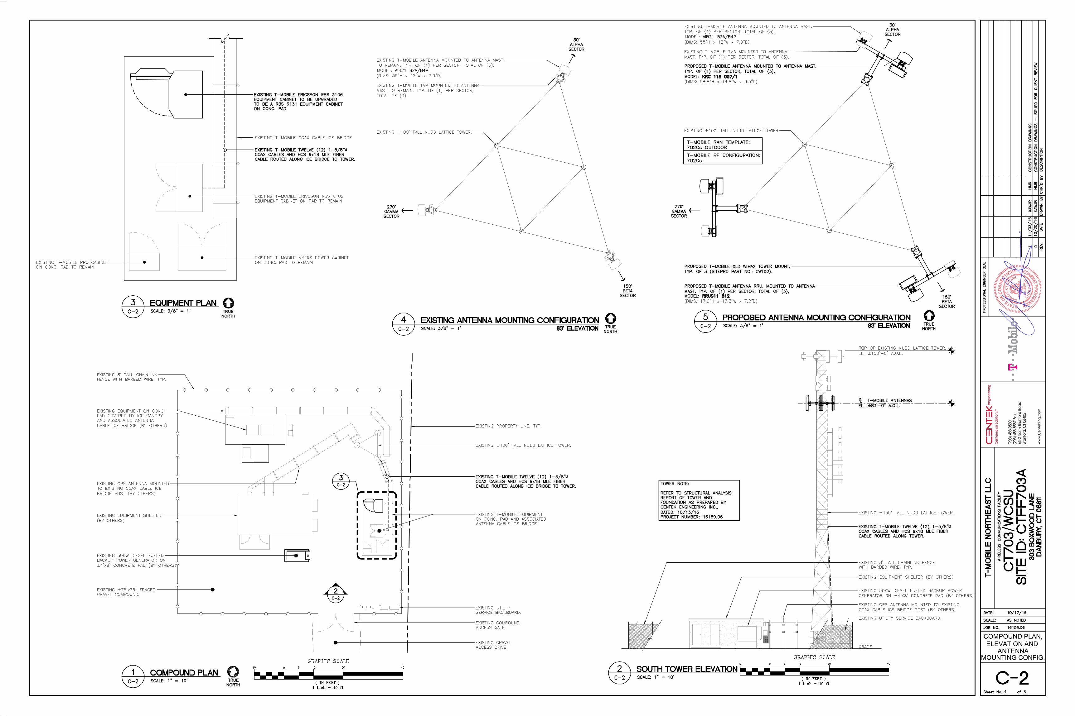
1. The proposed modifications will not result in an increase in the height of the existing structure. T-Mobile proposes to add three (3) L700 antennas, at a centerline of 83' on the existing 100' structure, as well
as add (3) RRUS and remove (6) coax cables.
2. The proposed modifications will not require the extension of the site boundary. There will be no effect on the site compound or T-Mobile's leased area.
3. The proposed modifications will not increase noise levels at the facility
by six decibels or more, or to levels that exceed state and local criteria. The incremental effect of the proposed changes will be
negligible.
4. The operation of the replacement antennas will not increase radio frequency emissions at the facility to a level at or above the Federal
Communications Commission safety standard. As indicated in the attached power density calculations, T-Mobile's operations at the site will result in a power density of 7.83%; the combined site operations
will result in a total power density of 28.66%.
5. The proposed modifications will not cause a change or alteration in the physical or environmental characteristics of the site. T-Mobile will swap antennas on the existing mounts.
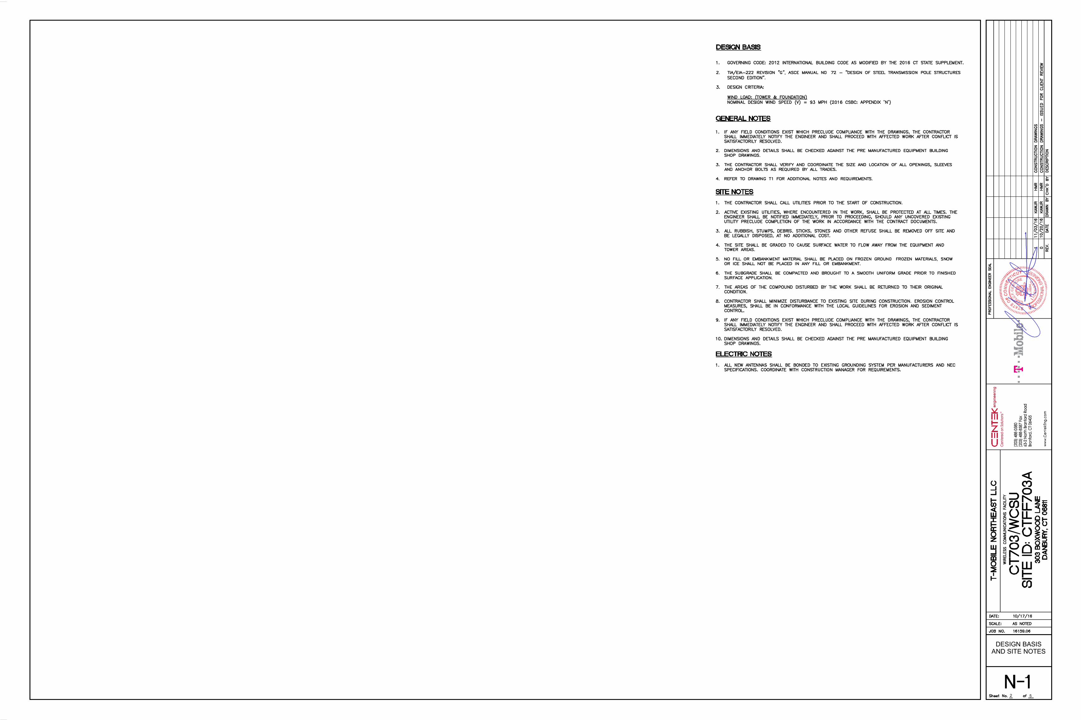
6. The existing structure and its foundation can support T-Mobile’s
proposed loading, as indicated in the attached structural analysis.
For the foregoing reasons, T-Mobile respectfully submits that the proposed modifications to the above-referenced telecommunications facility constitute
an exempt modification under R.C.S.A. J 6-50j-72(b)(2) .
Please feel free to call me with any questions or concerns regarding this matter. Thank you for your consideration.
Respectfully submitted,
By: _____________________ Jamie Ford, Agent for T-Mobile
[email protected] 774-248-5373
Attachments
cc: Mayor Mark D. Boughton, City of Danbury
Western Connecticut State University
TITLESHEET
1 5
PROJECTLOCATION
WIRELESS COMMUNICATIONS FACILITY
DESIGN BASISAND SITE NOTES
2 5
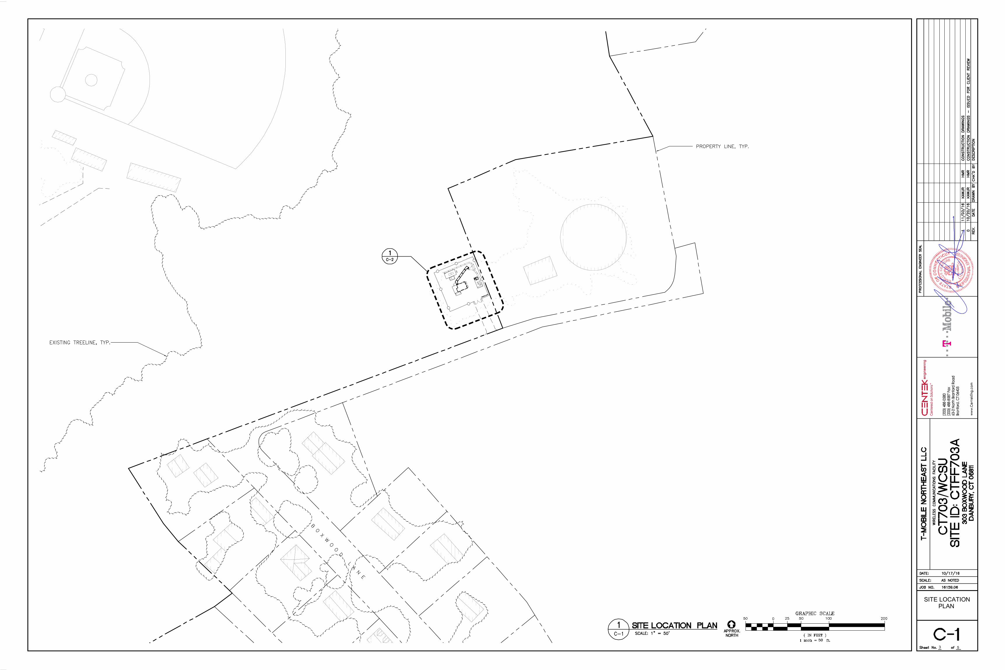
SITE LOCATIONPLAN
3 5
5
COMPOUND PLAN,ELEVATION AND
ANTENNA
4
MOUNTING CONFIG.
5
ANTENNA DETAILS
5
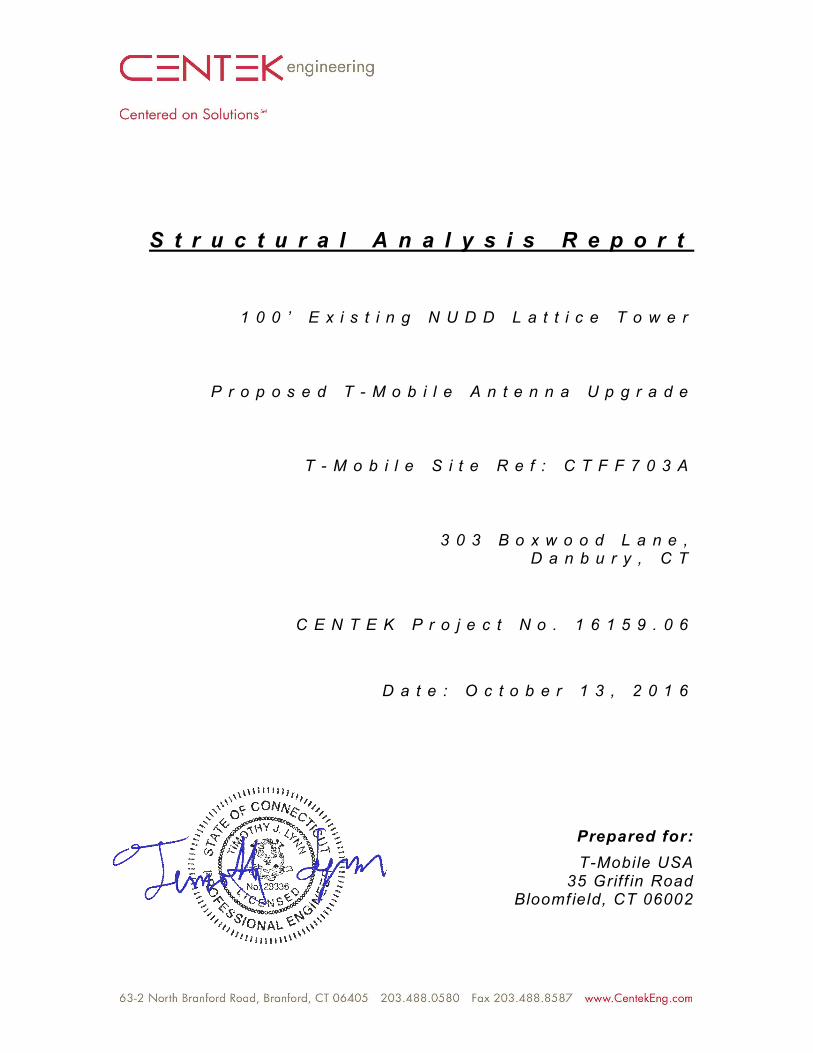
S t r u c t u r a l A n a l y s i s R e p o r t
1 0 0 ’ E x i s t i n g N U D D L a t t i c e T o w e r
P r o p o s e d T - M o b i l e A n t e n n a U p g r a d e
T - M o b i l e S i t e R e f : C T F F 7 0 3 A
3 0 3 B o x w o o d L a n e ,D a n b u r y , C T
C E N T E K P r o j e c t N o . 1 6 1 5 9 . 0 6
D a t e : O c t o b e r 1 3 , 2 0 1 6
Prepared for:T-Mobile USA
35 Griff in RoadBloomf ield, CT 06002
CENTEK Engineering, Inc.Structural Analysis - 100-ft NUDD Lattice TowerT-Mobile Antenna Upgrade – CTFF703ADanbury, CTOctober 13, 2016
TABLE OF CONTENTS TOC-1
T a b l e o f C o n t e n t sSECTION 1 - REPORT
§ INTRODUCTION§ ANTENNA AND APPURTENANCE SUMMARY§ PRIMARY ASSUMPTIONS USED IN THE ANALYSIS§ ANALYSIS§ TOWER LOADING§ TOWER CAPACITY§ FOUNDATION AND ANCHORS§ CONCLUSION
SECTION 2 – CONDITIONS & SOFTWARE
§ STANDARD ENGINEERING CONDITIONS§ GENERAL DESCRIPTION OF STRUCTURAL ANALYSIS PROGRAM
SECTION 3 – CALCULATIONS
§ tnxTower INPUT/OUTPUT SUMMARY§ tnxTower FEDLINE PLAN§ tnxTower FEDLINE DISTRIBUTION§ tnxTower DETAILED OUTPUT§ FOUNDATION ANALYSIS
SECTION 4 – REFERENCE MATERIAL
§ RF DATA SHEET§ ANTENNA CUT SHEETS
CENTEK Engineering, Inc.Structural Analysis - 100-ft NUDD Lattice TowerT-Mobile Antenna Upgrade – CTFF703ADanbury, CTOctober 13, 2016
REPORT SECTION 1-1
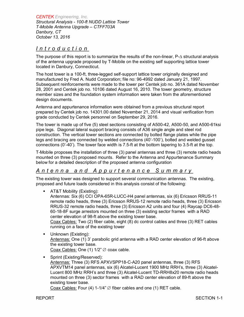
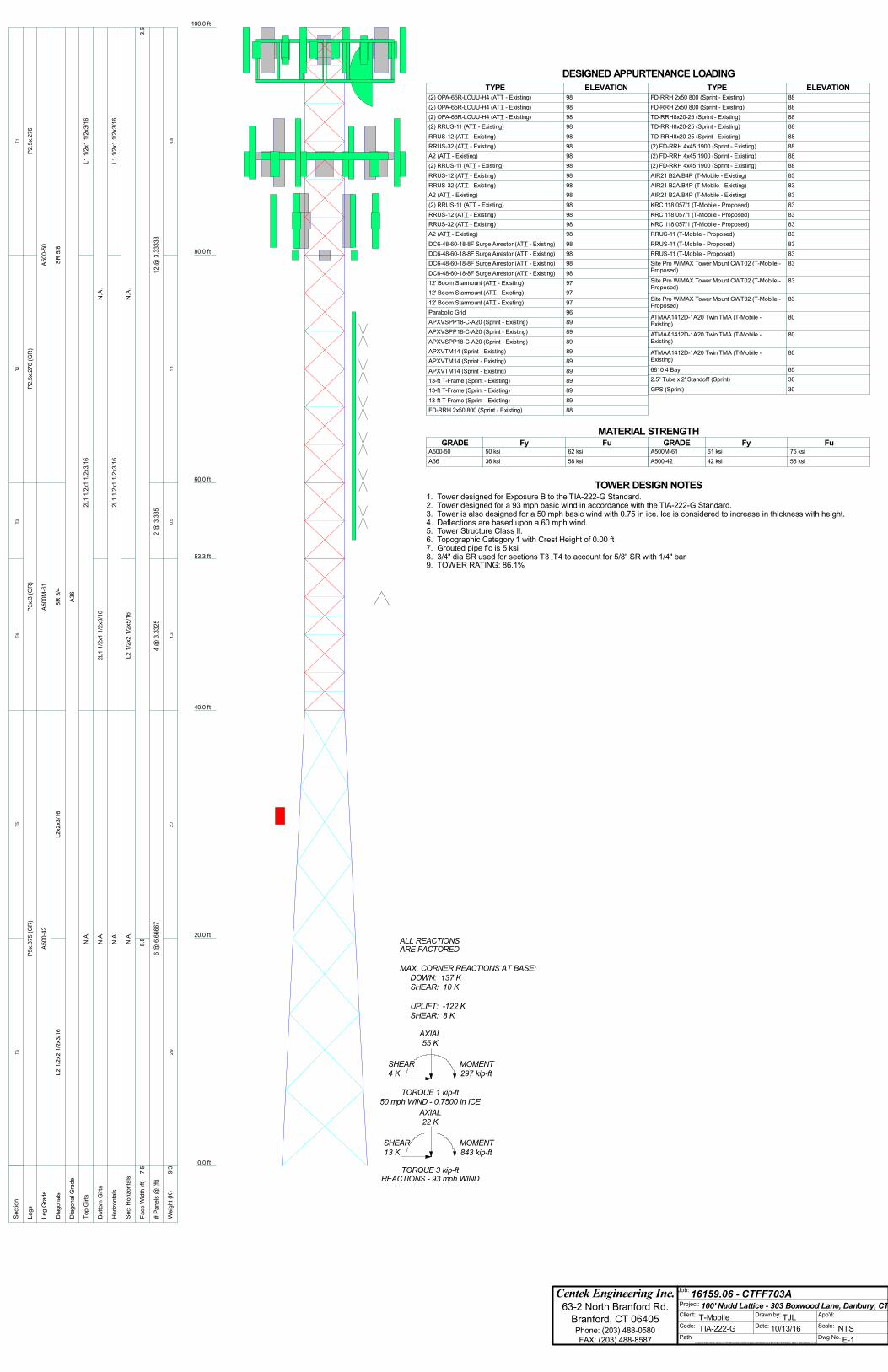
I n t r o d u c t i o nThe purpose of this report is to summarize the results of the non-linear, P-∆ structural analysisof the antenna upgrade proposed by T-Mobile on the existing self supporting lattice towerlocated in Danbury, Connecticut.The host tower is a 100-ft, three-legged self-support lattice tower originally designed andmanufactured by Fred A. Nudd Corporation; file no: 96-4992 dated January 21, 1997.Subsequent reinforcements were made to the tower per Centek job no. 361A dated November28, 2001 and Centek job no. 10106 dated August 16, 2010. The tower geometry, structuremember sizes and the foundation system information were taken from the aforementioneddesign documents.Antenna and appurtenance information were obtained from a previous structural reportprepared by Centek job no. 14301.00 dated November 21, 2014 and visual verification fromgrade conducted by Centek personnel on September 29, 2016.The tower is made up of five (5) steel sections consisting of A500-42, A500-50, and A500-61ksipipe legs. Diagonal lateral support bracing consists of A36 single angle and steel rodconstruction. The vertical tower sections are connected by bolted flange plates while the pipelegs and bracing are connected by welded connections (40’-100’), bolted and welded gussetconnections (0’-40’). The tower face width is 7.5-ft at the bottom tapering to 3.5-ft at the top.T-Mobile proposes the installation of three (3) panel antennas and three (3) remote radio headsmounted on three (3) proposed mounts. Refer to the Antenna and Appurtenance Summarybelow for a detailed description of the proposed antenna configuration
A n t e n n a a n d A p p u r t e n a n c e S u m m a r yThe existing tower was designed to support several communication antennas. The existing,proposed and future loads considered in this analysis consist of the following:§ AT&T Mobility (Existing):
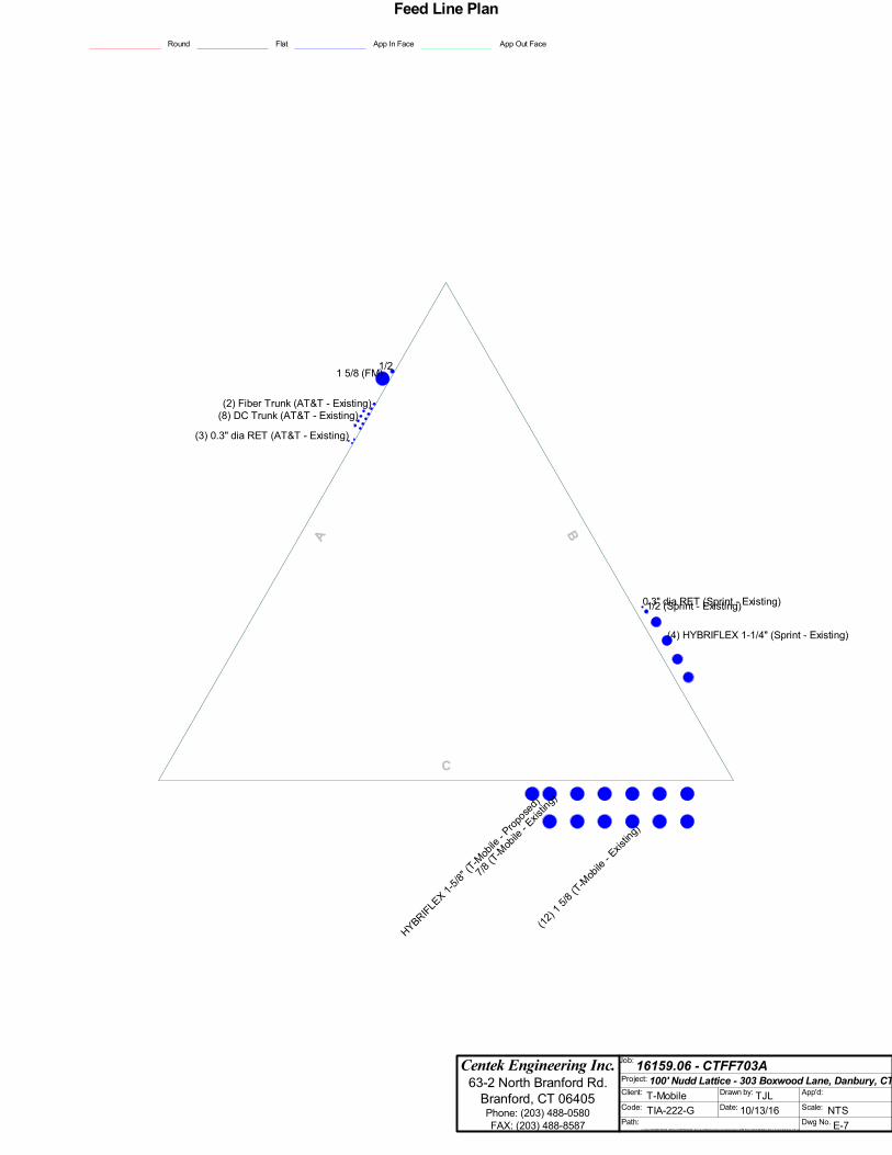
Antennas: Six (6) CCI OPA-65R-LUCC-H4 panel antennas, six (6) Ericsson RRUS-11remote radio heads, three (3) Ericsson RRUS-12 remote radio heads, three (3) EricssonRRUS-32 remote radio heads, three (3) Ericsson A2 units and four (4) Raycap DC6-48-60-18-8F surge arrestors mounted on three (3) existing sector frames with a RADcenter elevation of 98-ft above the existing tower base.Coax Cables: Two (2) fiber cable, eight (8) dc control cables and three (3) RET cablesrunning on a face of the existing tower
§ Unknown (Existing):Antennas: One (1) 3’ parabolic grid antenna with a RAD center elevation of 96-ft abovethe existing tower base.Coax Cables: One (1) 1/2” Æ coax cable.
§ Sprint (Existing/Reserved):Antennas: Three (3) RFS APXVSPP18-C-A20 panel antennas, three (3) RFSAPXVTM14 panel antennas, six (6) Alcatel-Lucent 1900 MHz RRH’s, three (3) Alcatel-Lucent 800 MHz RRH’s and three (3) Alcatel-Lucent TD-RRH8x20 remote radio headsmounted on three (3) sector frames with a RAD center elevation of 89-ft above theexisting tower base.Coax Cables: Four (4) 1-1/4” Æ fiber cables and one (1) RET cable.
CENTEK Engineering, Inc.Structural Analysis - 100-ft NUDD Lattice TowerT-Mobile Antenna Upgrade – CTFF703ADanbury, CTOctober 13, 2016
REPORT SECTION 1-2
§ WCSU FM (Existing):Antennas: One (1) 4-Bay Shively Labs 6810 FM Antenna w/ Radomes with a RADcenter elevation of 65-ft above the existing tower base.Coax Cables: One (1) 1 5/8” Æ coax cable.
§ Sprint (Existing):Antennas: (1) GPS antenna mounted to a 2’ standoff mount with a RAD center elevationof 30-ft above the existing tower base.Coax Cables: One (1) 1/2” Æ coax cable.
§ T-Mobile: (Existing to Remain):Antennas: Three (3) Ericsson AIR21 panel antennas and three (3) TMA’s relocated tonew antenna mounts with a RAD center elevation of 83-ft above the existing tower base.Coax Cables: Twelve (12) 1 5/8” Æ and one (1) 7/8” Æ coax cables.
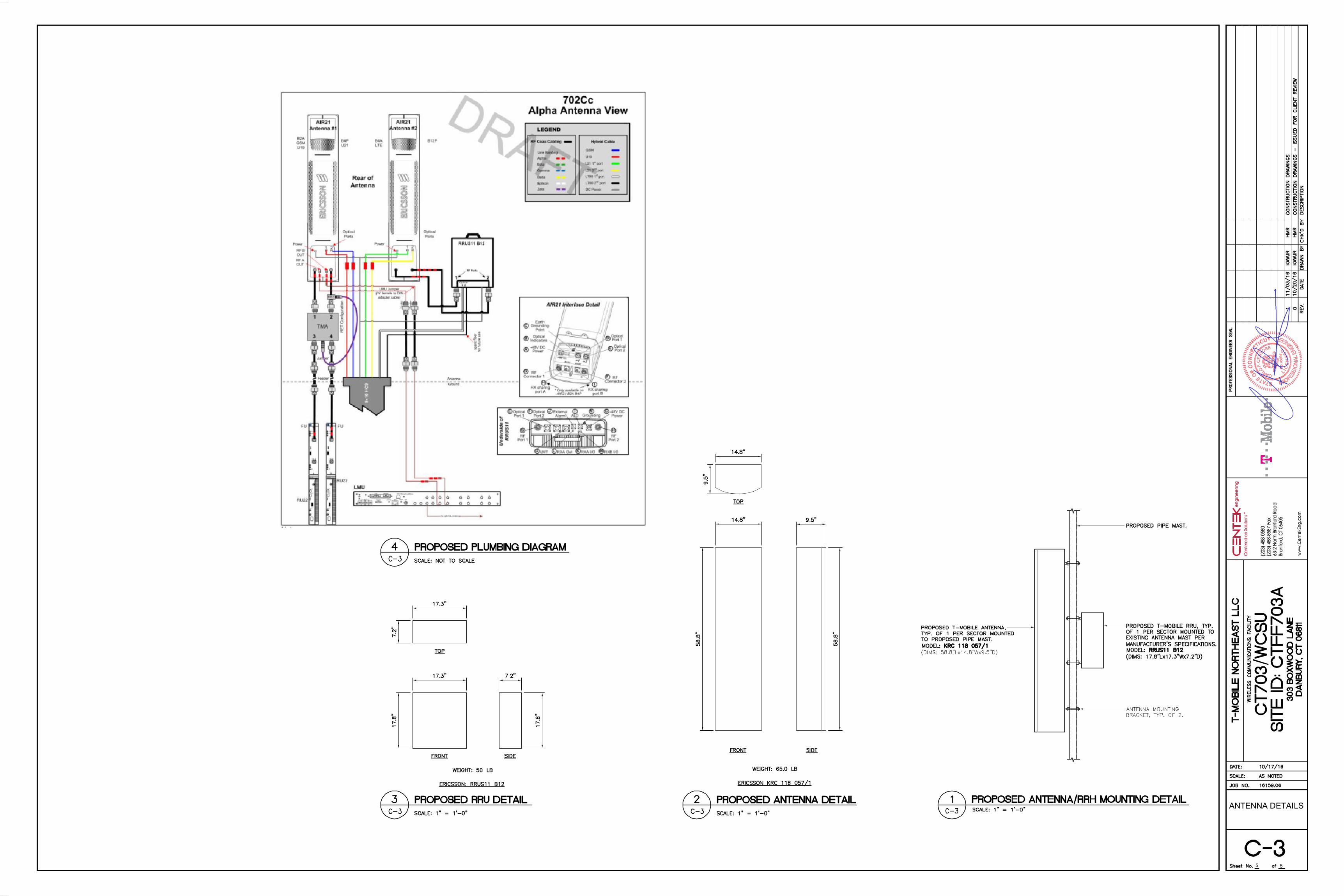
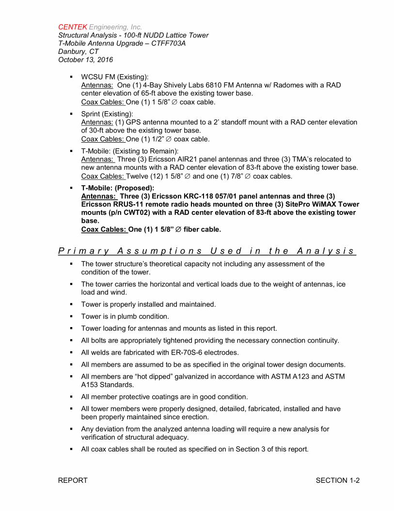
§ T-Mobile: (Proposed):Antennas: Three (3) Ericsson KRC-118 057/01 panel antennas and three (3)Ericsson RRUS-11 remote radio heads mounted on three (3) SitePro WiMAX Towermounts (p/n CWT02) with a RAD center elevation of 83-ft above the existing towerbase.Coax Cables: One (1) 1 5/8” Æ fiber cable.
P r i m a r y A s s u m p t i o n s U s e d i n t h e A n a l y s i s§ The tower structure’s theoretical capacity not including any assessment of the
condition of the tower.§ The tower carries the horizontal and vertical loads due to the weight of antennas, ice
load and wind.§ Tower is properly installed and maintained.§ Tower is in plumb condition.§ Tower loading for antennas and mounts as listed in this report.§ All bolts are appropriately tightened providing the necessary connection continuity.§ All welds are fabricated with ER-70S-6 electrodes.§ All members are assumed to be as specified in the original tower design documents.§ All members are “hot dipped” galvanized in accordance with ASTM A123 and ASTM
A153 Standards.§ All member protective coatings are in good condition.§ All tower members were properly designed, detailed, fabricated, installed and have
been properly maintained since erection.§ Any deviation from the analyzed antenna loading will require a new analysis for
verification of structural adequacy.§ All coax cables shall be routed as specified on in Section 3 of this report.
CENTEK Engineering, Inc.Structural Analysis - 100-ft NUDD Lattice TowerT-Mobile Antenna Upgrade – CTFF703ADanbury, CTOctober 13, 2016
REPORT SECTION 1-3
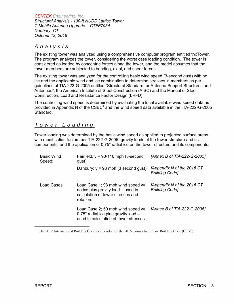
A n a l y s i sThe existing tower was analyzed using a comprehensive computer program entitled tnxTower.The program analyzes the tower, considering the worst case loading condition. The tower isconsidered as loaded by concentric forces along the tower, and the model assumes that thetower members are subjected to bending, axial, and shear forces.The existing tower was analyzed for the controlling basic wind speed (3-second gust) with noice and the applicable wind and ice combination to determine stresses in members as perguidelines of TIA-222-G-2005 entitled “Structural Standard for Antenna Support Structures andAntennas”, the American Institute of Steel Construction (AISC) and the Manual of SteelConstruction; Load and Resistance Factor Design (LRFD).The controlling wind speed is determined by evaluating the local available wind speed data asprovided in Appendix N of the CSBC1 and the wind speed data available in the TIA-222-G-2005Standard.
T o w e r L o a d i n g
Tower loading was determined by the basic wind speed as applied to projected surface areaswith modification factors per TIA-222-G-2005, gravity loads of the tower structure and itscomponents, and the application of 0.75” radial ice on the tower structure and its components.
Basic WindSpeed:
Fairfield; v = 90-110 mph (3-secondgust)Danbury; v = 93 mph (3 second gust)
[Annex B of TIA-222-G-2005]
[Appendix N of the 2016 CTBuilding Code]
Load Cases: Load Case 1; 93 mph wind speed w/no ice plus gravity load – used incalculation of tower stresses androtation.
[Appendix N of the 2016 CTBuilding Code]
Load Case 2; 50 mph wind speed w/0.75” radial ice plus gravity load –used in calculation of tower stresses.
[Annex B of TIA-222-G-2005]
1 The 2012 International Building Code as amended by the 2016 Connecticut State Building Code (CSBC).
CENTEK Engineering, Inc.Structural Analysis - 100-ft NUDD Lattice TowerT-Mobile Antenna Upgrade – CTFF703ADanbury, CTOctober 13, 2016
REPORT SECTION 1-4
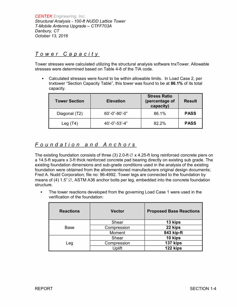
T o w e r C a p a c i t y
Tower stresses were calculated utilizing the structural analysis software tnxTower. Allowablestresses were determined based on Table 4-8 of the TIA code.
§ Calculated stresses were found to be within allowable limits. In Load Case 2, pertnxtower “Section Capacity Table”, this tower was found to be at 86.1% of its totalcapacity.
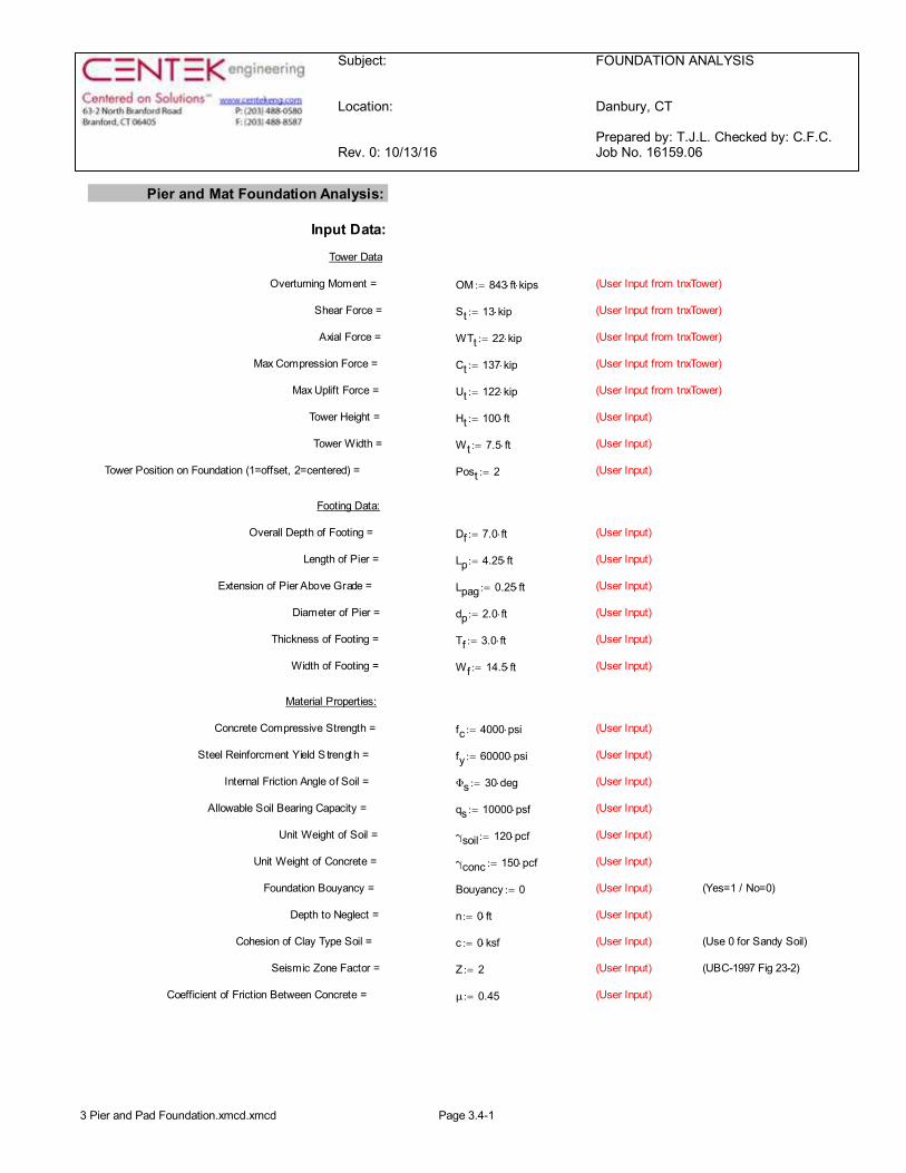
F o u n d a t i o n a n d A n c h o r s
The existing foundation consists of three (3) 2.0-ft Æ x 4.25-ft long reinforced concrete piers ona 14.5-ft square x 3-ft thick reinforced concrete pad bearing directly on existing sub grade. Theexisting foundation dimensions and sub-grade conditions used in the analysis of the existingfoundation were obtained from the aforementioned manufacturers original design documents;Fred A. Nudd Corporation; file no: 96-4992. Tower legs are connected to the foundation bymeans of (4) 1.5” Æ, ASTM A36 anchor bolts per leg, embedded into the concrete foundationstructure.§ The tower reactions developed from the governing Load Case 1 were used in the verification of the foundation:
Tower Section ElevationStress Ratio
(percentage ofcapacity)
Result
Diagonal (T2) 60’-0”-80’-0” 86.1% PASS
Leg (T4) 40’-0”-53’-4” 82.2% PASS
Reactions Vector Proposed Base Reactions
BaseShear 13 kips
Compression 22 kipsMoment 843 kip-ft
LegShear 10 kips
Compression 137 kipsUplift 122 kips
CENTEK Engineering, Inc.Structural Analysis - 100-ft NUDD Lattice TowerT-Mobile Antenna Upgrade – CTFF703ADanbury, CTOctober 13, 2016
REPORT SECTION 1-5
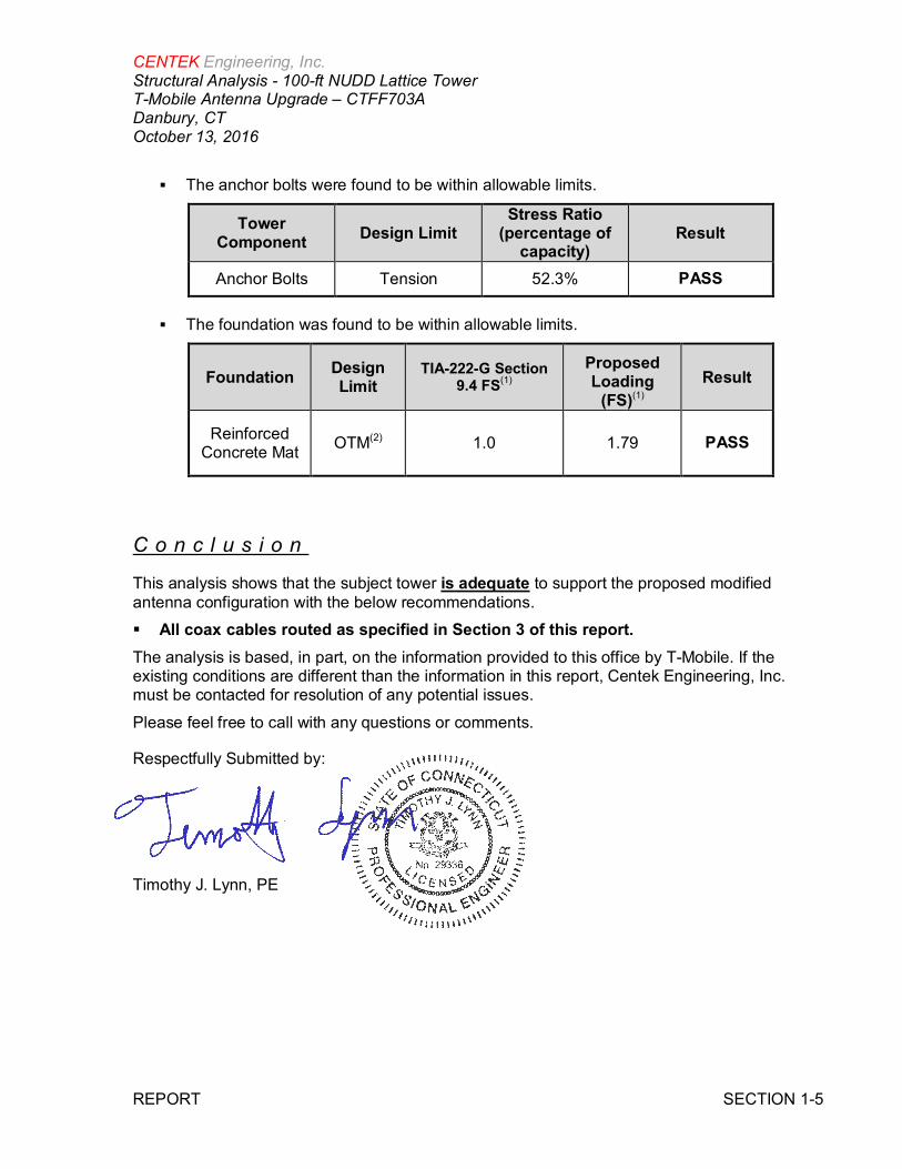
§ The anchor bolts were found to be within allowable limits.
TowerComponent Design Limit
Stress Ratio(percentage of
capacity)Result
Anchor Bolts Tension 52.3% PASS
§ The foundation was found to be within allowable limits.
Foundation DesignLimit
TIA-222-G Section9.4 FS(1)
ProposedLoading
(FS)(1)Result
ReinforcedConcrete Mat OTM(2) 1.0 1.79 PASS
C o n c l u s i o n
This analysis shows that the subject tower is adequate to support the proposed modifiedantenna configuration with the below recommendations.§ All coax cables routed as specified in Section 3 of this report.The analysis is based, in part, on the information provided to this office by T-Mobile. If theexisting conditions are different than the information in this report, Centek Engineering, Inc.must be contacted for resolution of any potential issues.Please feel free to call with any questions or comments.
Respectfully Submitted by:
Timothy J. Lynn, PE
CENTEK Engineering, Inc.Structural Analysis - 100-ft NUDD Lattice TowerT-Mobile Antenna Upgrade – CTFF703ADanbury, CTOctober 13, 2016
REPORT SECTION 2-1
S t a n d a r d C o n d i t i o n s f o r F u r n i s h i n g o fP r o f e s s i o n a l E n g i n e e r i n g S e r v i c e s o nE x i s t i n g S t r u c t u r e s
All engineering services are performed on the basis that the information used is current andcorrect. This information may consist of, but is not necessarily limited to:§ Information supplied by the client regarding the structure itself, its foundations, the soil conditions, the antenna and feed line loading on the structure and its components, or other relevant information.§ Information from the field and/or drawings in the possession of CENTEK engineering, Inc. or generated by field inspections or measurements of the structure.§ It is the responsibility of the client to ensure that the information provide to CENTEK engineering, Inc. and used in the performance of our engineering services is correct and complete. In the absence of information to the contrary, we assume that all structures were constructed in accordance with the drawings and specifications and are in an un- corroded condition and have not deteriorated. It is therefore assumed that its capacity has not significantly changed from the “as new” condition.§ All services will be performed to the codes specified by the client, and we do not imply to meet any other codes or requirements unless explicitly agreed in writing. If wind and ice loads or other relevant parameters are to be different from the minimum values recommended by the codes, the client shall specify the exact requirement. In the absence of information to the contrary, all work will be performed in accordance with the latest revision of ANSI/ASCE10 & ANSI/EIA-222§ All services performed, results obtained, and recommendations made are in accordance with generally accepted engineering principles and practices. CENTEK engineering, Inc. is not responsible for the conclusions, opinions and recommendations made by others based on the information we supply.
CENTEK Engineering, Inc.Structural Analysis - 100-ft NUDD Lattice TowerT-Mobile Antenna Upgrade – CTFF703ADanbury, CTOctober 13, 2016
REPORT SECTION 2-2
G e n e r a l D e s c r i p t i o n o f S t r u c t u r a lA n a l y s i s P r o g r a mtnxTower, is an integrated structural analysis and design software package for Designedspecifically for the telecommunications industry, tnxTower, formerly ERITower, automates muchof the tower analysis and design required by the TIA/EIA 222 Standard.tnxTower Features:§ tnxTower can analyze and design 3- and 4-sided guyed towers, 3- and 4-sided self- supporting towers and either round or tapered ground mounted poles with or without guys.§ The program analyzes towers using the TIA-222-G (2005) standard or any of the previous TIA/EIA standards back to RS-222 (1959). Steel design is checked using the AISC ASD 9th Edition or the AISC LRFD specifications.§ Linear and non-linear (P-delta) analyses can be used in determining displacements and forces in the structure. Wind pressures and forces are automatically calculated.§ Extensive graphics plots include material take-off, shear-moment, leg compression, displacement, twist, feed line, guy anchor and stress plots.§ tnxTower contains unique features such as True Cable behavior, hog rod take-up, foundation stiffness and much more.
Centek Engineering Inc. 63-2 North Branford Rd.
Branford, CT 06405 Phone: (203) 488-0580 FAX: (203) 488-8587
Job: 16159.06 - CTFF703A Project: 100' Nudd Lattice - 303 Boxwood Lane, Danbury, CT Client: T-Mobile Drawn by: TJL App'd:
Code: TIA-222-G Date: 10/13/16 Scale: NTS Path:
J:\Jobs\1615900.WI\06_WCSU CTFF703A\05_Structural\Backup Documentation\Calcs\ERI Files\100-ft NUDD Lattice Tower Danbury, CT.eri
Dwg No. E-1
100.0 ft
80.0 ft
60.0 ft
53.3 ft
40.0 ft
20.0 ft
0.0 ft
REACTIONS - 93 mph WINDTORQUE 3 kip-ft
13 KSHEAR
843 kip-ftMOMENT
22 KAXIAL
50 mph WIND - 0.7500 in ICETORQUE 1 kip-ft
4 KSHEAR
297 kip-ftMOMENT
55 KAXIAL
SHEAR: 8 KUPLIFT: -122 K
SHEAR: 10 KDOWN: 137 K
MAX. CORNER REACTIONS AT BASE:
ARE FACTOREDALL REACTIONS
Sect
ion
T1T2
T3T4
T5T6
Legs
P2.5
x.27
6P2
.5x.
276
(GR
)P3
x.3
(GR
)P5
x.37
5(G
R)
Leg
Gra
deA5
00-5
0A5
00M
-61
A500
-42
Dia
gona
lsSR
5/8
SR3/
4L2
x2x3
/16
L21/
2x2
1/2x
3/16
Dia
gona
lGra
deA3
6
Top
Girt
sL1
1/2x
11/
2x3/
162L
11/
2x1
1/2x
3/16
N.A
.
Botto
mG
irts
N.A
.2L
11/
2x1
1/2x
3/16
N.A
.
Hor
izon
tals
L11/
2x1
1/2x
3/16
2L1
1/2x
11/
2x3/
16N
.A.
Sec.
Hor
izon
tals
N.A
.L2
1/2x
21/
2x5/
16N
.A.
Face
Wid
th(ft
)3.
55.
57.
5
#Pa
nels
@(ft
)12
@3.
3333
32
@3.
335
4@
3.33
256
@6.
6666
7
Wei
ght(
K)0.
81.
10.
51.
32.
72.
99.
3
(2) OPA-65R-LCUU-H4 (ATT - Existing) 98(2) OPA-65R-LCUU-H4 (ATT - Existing) 98(2) OPA-65R-LCUU-H4 (ATT - Existing) 98(2) RRUS-11 (ATT - Existing) 98RRUS-12 (ATT - Existing) 98RRUS-32 (ATT - Existing) 98A2 (ATT - Existing) 98(2) RRUS-11 (ATT - Existing) 98RRUS-12 (ATT - Existing) 98RRUS-32 (ATT - Existing) 98A2 (ATT - Existing) 98(2) RRUS-11 (ATT - Existing) 98RRUS-12 (ATT - Existing) 98RRUS-32 (ATT - Existing) 98A2 (ATT - Existing) 98DC6-48-60-18-8F Surge Arrestor (ATT - Existing) 98DC6-48-60-18-8F Surge Arrestor (ATT - Existing) 98DC6-48-60-18-8F Surge Arrestor (ATT - Existing) 98DC6-48-60-18-8F Surge Arrestor (ATT - Existing) 9812' Boom Starmount (ATT - Existing) 9712' Boom Starmount (ATT - Existing) 9712' Boom Starmount (ATT - Existing) 97Parabolic Grid 96APXVSPP18-C-A20 (Sprint - Existing) 89APXVSPP18-C-A20 (Sprint - Existing) 89APXVSPP18-C-A20 (Sprint - Existing) 89APXVTM14 (Sprint - Existing) 89APXVTM14 (Sprint - Existing) 89APXVTM14 (Sprint - Existing) 8913-ft T-Frame (Sprint - Existing) 8913-ft T-Frame (Sprint - Existing) 8913-ft T-Frame (Sprint - Existing) 89FD-RRH 2x50 800 (Sprint - Existing) 88FD-RRH 2x50 800 (Sprint - Existing) 88FD-RRH 2x50 800 (Sprint - Existing) 88TD-RRH8x20-25 (Sprint - Existing) 88TD-RRH8x20-25 (Sprint - Existing) 88TD-RRH8x20-25 (Sprint - Existing) 88(2) FD-RRH 4x45 1900 (Sprint - Existing) 88(2) FD-RRH 4x45 1900 (Sprint - Existing) 88(2) FD-RRH 4x45 1900 (Sprint - Existing) 88AIR21 B2A/B4P (T-Mobile - Existing) 83AIR21 B2A/B4P (T-Mobile - Existing) 83AIR21 B2A/B4P (T-Mobile - Existing) 83KRC 118 057/1 (T-Mobile - Proposed) 83KRC 118 057/1 (T-Mobile - Proposed) 83KRC 118 057/1 (T-Mobile - Proposed) 83RRUS-11 (T-Mobile - Proposed) 83RRUS-11 (T-Mobile - Proposed) 83RRUS-11 (T-Mobile - Proposed) 83Site Pro WiMAX Tower Mount CWT02 (T-Mobile -Proposed)
83Site Pro WiMAX Tower Mount CWT02 (T-Mobile -Proposed)
83Site Pro WiMAX Tower Mount CWT02 (T-Mobile -Proposed)
83ATMAA1412D-1A20 Twin TMA (T-Mobile -Existing)
80ATMAA1412D-1A20 Twin TMA (T-Mobile -Existing)
80ATMAA1412D-1A20 Twin TMA (T-Mobile -Existing)
806810 4 Bay 652.5" Tube x 2' Standoff (Sprint) 30GPS (Sprint) 30DESIGNED APPURTENANCE LOADINGTYPE TYPEELEVATION ELEVATION
(2) OPA-65R-LCUU-H4 (ATT - Existing) 98(2) OPA-65R-LCUU-H4 (ATT - Existing) 98(2) OPA-65R-LCUU-H4 (ATT - Existing) 98(2) RRUS-11 (ATT - Existing) 98RRUS-12 (ATT - Existing) 98RRUS-32 (ATT - Existing) 98A2 (ATT - Existing) 98(2) RRUS-11 (ATT - Existing) 98RRUS-12 (ATT - Existing) 98RRUS-32 (ATT - Existing) 98A2 (ATT - Existing) 98(2) RRUS-11 (ATT - Existing) 98RRUS-12 (ATT - Existing) 98RRUS-32 (ATT - Existing) 98A2 (ATT - Existing) 98DC6-48-60-18-8F Surge Arrestor (ATT - Existing) 98DC6-48-60-18-8F Surge Arrestor (ATT - Existing) 98DC6-48-60-18-8F Surge Arrestor (ATT - Existing) 98DC6-48-60-18-8F Surge Arrestor (ATT - Existing) 9812' Boom Starmount (ATT - Existing) 9712' Boom Starmount (ATT - Existing) 9712' Boom Starmount (ATT - Existing) 97Parabolic Grid 96APXVSPP18-C-A20 (Sprint - Existing) 89APXVSPP18-C-A20 (Sprint - Existing) 89APXVSPP18-C-A20 (Sprint - Existing) 89APXVTM14 (Sprint - Existing) 89APXVTM14 (Sprint - Existing) 89APXVTM14 (Sprint - Existing) 8913-ft T-Frame (Sprint - Existing) 8913-ft T-Frame (Sprint - Existing) 8913-ft T-Frame (Sprint - Existing) 89FD-RRH 2x50 800 (Sprint - Existing) 88
FD-RRH 2x50 800 (Sprint - Existing) 88FD-RRH 2x50 800 (Sprint - Existing) 88TD-RRH8x20-25 (Sprint - Existing) 88TD-RRH8x20-25 (Sprint - Existing) 88TD-RRH8x20-25 (Sprint - Existing) 88(2) FD-RRH 4x45 1900 (Sprint - Existing) 88(2) FD-RRH 4x45 1900 (Sprint - Existing) 88(2) FD-RRH 4x45 1900 (Sprint - Existing) 88AIR21 B2A/B4P (T-Mobile - Existing) 83AIR21 B2A/B4P (T-Mobile - Existing) 83AIR21 B2A/B4P (T-Mobile - Existing) 83KRC 118 057/1 (T-Mobile - Proposed) 83KRC 118 057/1 (T-Mobile - Proposed) 83KRC 118 057/1 (T-Mobile - Proposed) 83RRUS-11 (T-Mobile - Proposed) 83RRUS-11 (T-Mobile - Proposed) 83RRUS-11 (T-Mobile - Proposed) 83Site Pro WiMAX Tower Mount CWT02 (T-Mobile -Proposed)
83
Site Pro WiMAX Tower Mount CWT02 (T-Mobile -Proposed)
83
Site Pro WiMAX Tower Mount CWT02 (T-Mobile -Proposed)
83
ATMAA1412D-1A20 Twin TMA (T-Mobile -Existing)
80
ATMAA1412D-1A20 Twin TMA (T-Mobile -Existing)
80
ATMAA1412D-1A20 Twin TMA (T-Mobile -Existing)
80
6810 4 Bay 652.5" Tube x 2' Standoff (Sprint) 30GPS (Sprint) 30
MATERIAL STRENGTHGRADE GRADEFy FyFu Fu
A500-50 50 ksi 62 ksiA36 36 ksi 58 ksi
A500M-61 61 ksi 75 ksiA500-42 42 ksi 58 ksi
TOWER DESIGN NOTES1. Tower designed for Exposure B to the TIA-222-G Standard.2. Tower designed for a 93 mph basic wind in accordance with the TIA-222-G Standard.3. Tower is also designed for a 50 mph basic wind with 0.75 in ice. Ice is considered to increase in thickness with height.4. Deflections are based upon a 60 mph wind.5. Tower Structure Class II.6. Topographic Category 1 with Crest Height of 0.00 ft7. Grouted pipe f'c is 5 ksi8. 3/4" dia SR used for sections T3 T4 to account for 5/8" SR with 1/4" bar9. TOWER RATING: 86.1%
Centek Engineering Inc. 63-2 North Branford Rd.
Branford, CT 06405 Phone: (203) 488-0580 FAX: (203) 488-8587
Job: 16159.06 - CTFF703A Project: 100' Nudd Lattice - 303 Boxwood Lane, Danbury, CT Client: T-Mobile Drawn by: TJL App'd:
Code: TIA-222-G Date: 10/13/16 Scale: NTS Path:
J:\Jobs\1615900.WI\06_WCSU CTFF703A\05_Structural\Backup Documentation\Calcs\ERI Files\100-ft NUDD Lattice Tower Danbury, CT.eri
Dwg No. E-7
Feed Line Plan
Round Flat App In Face App Out Face
A B
C
1 5/8 (FM)1/2
(4) HYBRIFLEX 1-1/4" (Sprint - Existing)
1/2 (Sprint - Existing)0.3" dia RET (Sprint - Existing)
(12) 1 5/8
(T-Mob
ile- Exis
ting)
7/8(T-M
obile
- Existin
g)
(2) Fiber Trunk (AT&T - Existing)(8) DC Trunk (AT&T - Existing)
(3) 0.3" dia RET (AT&T - Existing)
HYBRIFLEX 1-5
/8"(T-M
obile
- Prop
osed
)
Centek Engineering Inc. 63-2 North Branford Rd.
Branford, CT 06405 Phone: (203) 488-0580 FAX: (203) 488-8587
Job: 16159.06 - CTFF703A Project: 100' Nudd Lattice - 303 Boxwood Lane, Danbury, CT Client: T-Mobile Drawn by: TJL App'd:
Code: TIA-222-G Date: 10/13/16 Scale: NTS Path:
J:\Jobs\1615900.WI\06_WCSU CTFF703A\05_Structural\Backup Documentation\Calcs\ERI Files\100-ft NUDD Lattice Tower Danbury, CT.eri
Dwg No. E-7
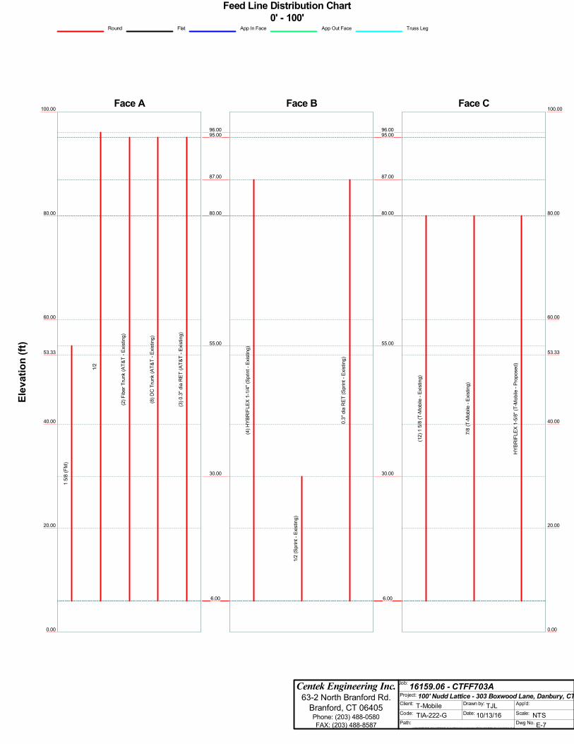
Feed Line Distribution Chart0' - 100'
Round Flat App In Face App Out Face Truss Leg
Face A
80.00
60.00
53.33
40.00
20.00
0.00
100.00
Elev
atio
n(ft
)
15/
8(F
M)
1/2
(2)F
iber
Trun
k(A
T&T
-Exi
stin
g)
(8)D
CTr
unk
(AT&
T-E
xist
ing)
(3)0
.3"d
iaR
ET(A
T&T
-Exi
stin
g)
Face B
6.00
55.00
6.00
96.00
6.00
87.00
6.00
30.00
6.00
87.00
6.00
80.00
6.00
80.00
6.00
95.00
6.00
95.00
6.00
95.00
6.00
80.00
(4)H
YBR
IFLE
X1-
1/4"
(Spr
int-
Exis
ting)
1/2
(Spr
int-
Exis
ting)
0.3"
dia
RET
(Spr
int-
Exis
ting)
Face C
80.00
60.00
53.33
40.00
20.00
0.00
100.00
6.00
55.00
6.00
96.00
6.00
87.00
6.00
30.00
6.00
87.00
6.00
80.00
6.00
80.00
6.00
95.00
6.00
95.00
6.00
95.00
6.00
80.00
(12)
15/
8(T
-Mob
ile-E
xist
ing)
7/8
(T-M
obile
-Exi
stin
g)
HYB
RIF
LEX
1-5/
8"(T
-Mob
ile-P
ropo
sed)
Subject:
Location:
Rev. 0: 10/13/16
FOUNDATION ANALYSIS
Danbury, CT
Prepared by: T.J.L. Checked by: C.F.C.Job No. 16159.06
Pier and Mat Foundation Analysis:
Input Data:
Tower Data
Overturning Moment = OM 843 ft× kips×:= (User Input from tnxTower)
Shear Force = St 13 kip×:= (User Input from tnxTower)
Axial Force = WTt 22 kip×:= (User Input from tnxTower)
Max Compression Force = Ct 137 kip×:= (User Input from tnxTower)
Max Uplift Force = Ut 122 kip×:= (User Input from tnxTower)
Tower Height = Ht 100 ft×:= (User Input)
Tower Width = Wt 7.5 ft×:= (User Input)
Tower Position on Foundation (1=offset, 2=centered) = Post 2:= (User Input)
Footing Data:
Overall Depth of Footing = Df 7.0 ft×:= (User Input)
Length of Pier = Lp 4.25 ft×:= (User Input)
Extension of Pier Above Grade = Lpag 0.25 ft×:= (User Input)
Diameter of Pier = dp 2.0 ft×:= (User Input)
Thickness of Footing = Tf 3.0 ft×:= (User Input)
Width of Footing = Wf 14.5 ft×:= (User Input)
Material Properties:
Concrete Compressive Strength = fc 4000 psi×:= (User Input)
Steel Reinforcment Yield S trength = fy 60000 psi×:= (User Input)
Internal Friction Angle of Soil = Φs 30 deg×:= (User Input)
Allowable Soil Bearing Capacity = qs 10000 psf×:= (User Input)
Unit Weight of Soil = γsoil 120 pcf×:= (User Input)
Unit Weight of Concrete = γconc 150 pcf×:= (User Input)
Foundation Bouyancy = Bouyancy 0:= (User Input) (Yes=1 / No=0)
Depth to Neglect = n 0 ft×:= (User Input)
Cohesion of Clay Type Soil = c 0 ksf×:= (User Input) (Use 0 for Sandy Soil)
Seismic Zone Factor = Z 2:= (User Input) (UBC-1997 Fig 23-2)
Coefficient of Friction Between Concrete = μ 0.45:= (User Input)
3 Pier and Pad Foundation.xmcd.xmcd Page 3.4-1
Subject:
Location:
Rev. 0: 10/13/16
FOUNDATION ANALYSIS
Danbury, CT
Prepared by: T.J.L. Checked by: C.F.C.Job No. 16159.06
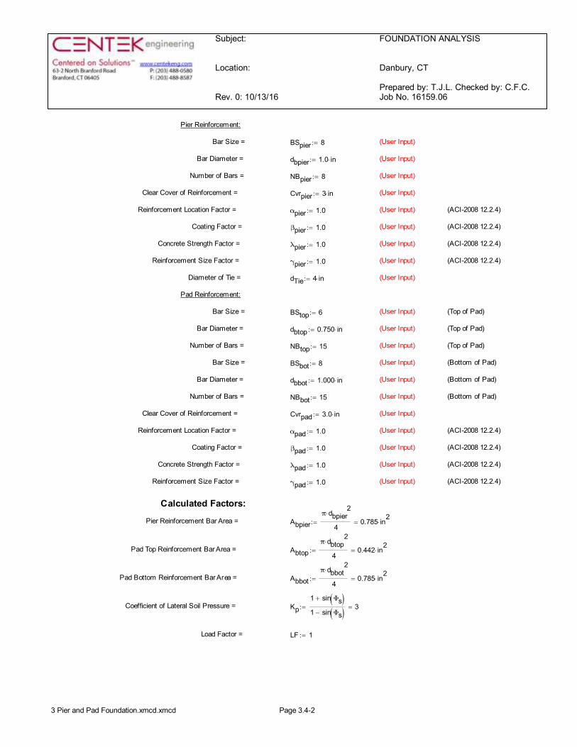
Pier Reinforcement:
Bar Size = BSpier 8:= (User Input)
Bar Diameter = dbpier 1.0 in×:= (User Input)
Number of Bars = NBpier 8:= (User Input)
Clear Cover of Reinforcement = Cvrpier 3 in×:= (User Input)
Reinforcement Location Factor = αpier 1.0:= (User Input) (ACI-2008 12.2.4)
Coating Factor = βpier 1.0:= (User Input) (ACI-2008 12.2.4)
Concrete Strength Factor = λpier 1.0:= (User Input) (ACI-2008 12.2.4)
Reinforcement Size Factor = γpier 1.0:= (User Input) (ACI-2008 12.2.4)
Diameter of Tie = dTie 4 in×:= (User Input)
Pad Reinforcement:
Bar Size = BStop 6:= (User Input) (Top of Pad)
Bar Diameter = dbtop 0.750 in×:= (User Input) (Top of Pad)
Number of Bars = NBtop 15:= (User Input) (Top of Pad)
Bar Size = BSbot 8:= (User Input) (Bottom of Pad)
Bar Diameter = dbbot 1.000 in×:= (User Input) (Bottom of Pad)
Number of Bars = NBbot 15:= (User Input) (Bottom of Pad)
Clear Cover of Reinforcement = Cvrpad 3.0 in×:= (User Input)
Reinforcement Location Factor = αpad 1.0:= (User Input) (ACI-2008 12.2.4)
Coating Factor = βpad 1.0:= (User Input) (ACI-2008 12.2.4)
Concrete Strength Factor = λpad 1.0:= (User Input) (ACI-2008 12.2.4)
Reinforcement Size Factor = γpad 1.0:= (User Input) (ACI-2008 12.2.4)
Calculated Factors:
Pier Reinforcement Bar Area = Abpierπ dbpier
2×
40.785 in
2×=:=
Pad Top Reinforcement Bar Area = Abtopπ dbtop
2×
40.442 in
2×=:=
Pad Bottom Reinforcement Bar Area = Abbotπ dbbot
2×
40.785 in
2×=:=
Coefficient of Lateral Soil Pressure = Kp1 sin Φs( )+
1 sin Φs( )-3=:=
Load Factor = LF 1:=
3 Pier and Pad Foundation.xmcd.xmcd Page 3.4-2
Subject:
Location:
Rev. 0: 10/13/16
FOUNDATION ANALYSIS
Danbury, CT
Prepared by: T.J.L. Checked by: C.F.C.Job No. 16159.06
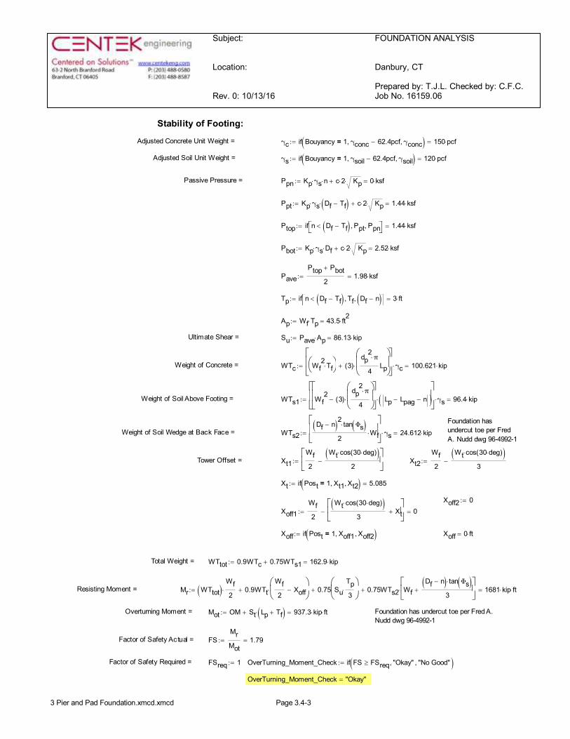
Stability of Footing:
Adjusted Concrete Unit Weight = γc if Bouyancy 1= γconc 62.4pcf-, γconc, ( ) 150 pcf×=:=
Adjusted Soil Unit Weight = γs if Bouyancy 1= γsoil 62.4pcf-, γsoil, ( ) 120 pcf×=:=
Passive Pressure = Ppn Kp γs× n× c 2× Kp×+ 0 ksf×=:=
Ppt Kp γs× Df Tf-( )× c 2× Kp×+ 1.44 ksf×=:=
Ptop if n Df Tf-( )< Ppt, Ppn, éë ùû 1.44 ksf×=:=
Pbot Kp γs× Df× c 2× Kp×+ 2.52 ksf×=:=
PavePtop Pbot+
21.98 ksf×=:=
Tp if n Df Tf-( )< Tf, Df n-( ), éë ùû 3 ft×=:=
Ap Wf Tp× 43.5 ft2
×=:=
Ultimate Shear = Su Pave Ap× 86.13 kip×=:=
Weight of Concrete = WTc Wf2
Tf×æè
öø 3( )
dp2π×
4Lp
æççè
ö÷÷ø
×+
éêêë
ùúúûγc× 100.621 kip×=:=
Weight of Soil Above Footing = WTs1 Wf2
3( )dp
2π×
4
æççè
ö÷÷ø
×-
éêêë
ùúúû
Lp Lpag- n-( )×
éêêë
ùúúûγs× 96.4 kip×=:=
Foundation hasundercut toe per FredA. Nudd dwg 96-4992-1
Weight of Soil Wedge at Back Face = WTs2Df n-( )2 tan Φs( )×
2Wf×
éêêë
ùúúûγs× 24.612 kip×=:=
Tower Offset = Xt1Wf2
Wt cos 30 deg×( )×( )2
-éêë
ùúû
:= Xt2Wf2
Wt cos 30 deg×( )×( )3
-:=
Xt if Post 1= Xt1, Xt2, ( ) 5.085=:=
Xoff2 0:=
Xoff1Wf2
Wt cos 30 deg×( )×( )3
Xt+éêë
ùúû
- 0=:=
Xoff if Post 1= Xoff1, Xoff2, ( ):= Xoff 0 ft×=
Total Weight = WTtot 0.9WTc 0.75WTs1+ 162.9 kip×=:=
Resisting Moment = Mr WTtot( )Wf2
× 0.9WTtWf2
Xoff-æçè
ö÷ø
×+ 0.75 SuTp3
×æçè
ö÷ø
+ 0.75WTs2 WfDf n-( ) tan Φs( )×
3+
éêë
ùúû
×+ 1681 kip ft××=:=
Overturning Moment = Mot OM St Lp Tf+( )×+ 937.3 kip ft××=:= Foundation has undercut toe per Fred A.Nudd dwg 96-4992-1
Factor of Safety Actual = FSMrMot
1.79=:=
Factor of Safety Required = FSreq 1:= OverTurning_Moment_Check if FS FSreq³ "Okay", "No Good", ( ):=
OverTurning_Moment_Check "Okay"=
3 Pier and Pad Foundation.xmcd.xmcd Page 3.4-3
Subject:
Location:
Rev. 0: 10/13/16
FOUNDATION ANALYSIS
Danbury, CT
Prepared by: T.J.L. Checked by: C.F.C.Job No. 16159.06
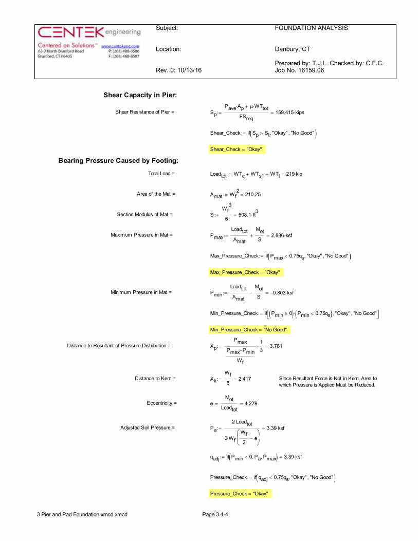
Shear Capacity in Pier:
Shear Resistance of Pier = SpPave Ap× μ WTtot×+
FSreq159.415 kips×=:=
Shear_Check if Sp St> "Okay", "No Good", ( ):=
Shear_Check "Okay"=
Bearing Pressure Caused by Footing:
Total Load = Loadtot WTc WTs1+ WTt+ 219 kip×=:=
Area of the Mat = Amat Wf2
210.25=:=
Section Modulus of Mat = SWf
3
6508.1 ft
3×=:=
Maximum Pressure in Mat = PmaxLoadtotAmat
MotS
+ 2.886 ksf×=:=
Max_Pressure_Check if Pmax 0.75qs< "Okay", "No Good", ( ):=
Max_Pressure_Check "Okay"=
Minimum Pressure in Mat = PminLoadtotAmat
MotS
- 0.803- ksf×=:=
Min_Pressure_Check if Pmin 0³( ) Pmin 0.75qs<( )× "Okay", "No Good", éë ùû:=
Min_Pressure_Check "No Good"=
Distance to Resultant of Pressure Distribution = XpPmax
Pmax Pmin-
Wf
13
× 3.781=:=
Distance to Kern = XkWf6
2.417=:= Since Resultant Force is Not in Kern, Area towhich Pressure is Applied Must be Reduced.
Eccentricity = eMot
Loadtot4.279=:=
Adjusted Soil Pressure = Pa2 Loadtot×
3 Wf×Wf2
e-æçè
ö÷ø
×
3.39 ksf×=:=
qadj if Pmin 0< Pa, Pmax, ( ) 3.39 ksf×=:=
Pressure_Check if qadj 0.75qs< "Okay", "No Good", ( ):=
Pressure_Check "Okay"=
3 Pier and Pad Foundation.xmcd.xmcd Page 3.4-4
Subject:
Location:
Rev. 0: 10/13/16
FOUNDATION ANALYSIS
Danbury, CT
Prepared by: T.J.L. Checked by: C.F.C.Job No. 16159.06
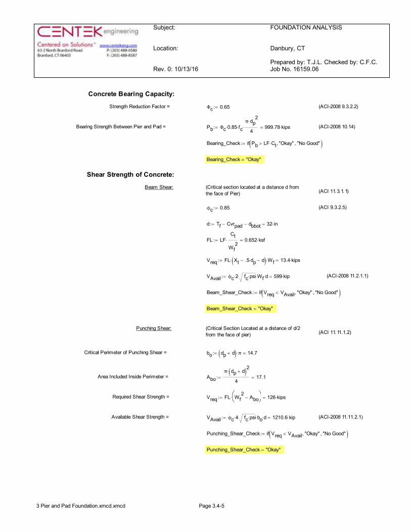
Concrete Bearing Capacity:
Strength Reduction Factor = Φc 0.65:= (ACI-2008 9.3.2.2)
Bearing Strength Between Pier and Pad = Pb Φc 0.85× fc×π dp
2×
4× 999.78 kips×=:= (ACI-2008 10.14)
Bearing_Check if Pb LF Ct×> "Okay", "No Good", ( ):=
Bearing_Check "Okay"=
Shear Strength of Concrete:
Beam Shear: (Critical section located at a distance d fromthe face of Pier) (ACI 11.3.1.1)
ϕc 0.85:= (ACI 9.3.2.5)
d Tf Cvrpad- dbbot- 32 in×=:=
FL LFCt
Wf2
× 0.652 ksf×=:=
Vreq FL Xt .5 dp×- d-( )× Wf× 13.4 kips×=:=
VAvail ϕc 2× fc psi×× Wf× d× 599 kip×=:= (ACI-2008 11.2.1.1)
Beam_Shear_Check if Vreq VAvail< "Okay", "No Good", ( ):=
Beam_Shear_Check "Okay"=
Punching Shear: (Critical Section Located at a distance of d/2from the face of pier) (ACI 11.11.1.2)
Critical Perimeter of Punching Shear = bo dp d+( ) π× 14.7=:=
Area Included Inside Perimeter = Aboπ dp d+( )2×
417.1=:=
Required Shear Strength = Vreq FL Wf2
Abo-æè
öø× 126 kips×=:=
Available Shear Strength = VAvail ϕc 4× fc psi×× bo× d× 1210.6 kip×=:= (ACI-2008 11.11.2.1)
Punching_Shear_Check if Vreq VAvail< "Okay", "No Good", ( ):=
Punching_Shear_Check "Okay"=
3 Pier and Pad Foundation.xmcd.xmcd Page 3.4-5
Subject:
Location:
Rev. 0: 10/13/16
FOUNDATION ANALYSIS
Danbury, CT
Prepared by: T.J.L. Checked by: C.F.C.Job No. 16159.06
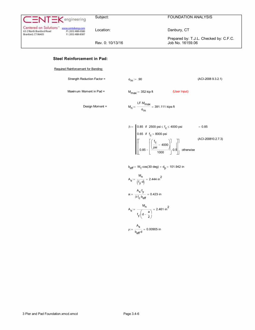
Steel Reinforcement in Pad:
Required Reinforcement for Bending:
Strength Reduction Factor = ϕm .90:= (ACI-2008 9.3.2.1)
Maximum Moment in Pad = Mmax 352 kip× ft×:= (User Input)
Design Moment = MnLF Mmax×
ϕm391.111 kips ft××=:=
β 0.85 2500 psi× fc£ 4000 psi×£if
0.65 fc 8000 psi×>if
0.85
fcpsi
4000-æçè
ö÷ø
1000
éêêë
ùúúû
0.5×-
éêêë
ùúúû
éêêë
ùúúû
otherwise
0.85=:=
(ACI-200810.2.7.3)
beff Wt cos 30 deg×( )× dp+ 101.942 in×=:=
AsMnfy d×( ) 2.444 in
2×=:=
aAs fy×
β fc× beff×0.423 in×=:=
AsMn
fy da2
-æçè
ö÷ø
×
2.461 in2
×=:=
ρAs
beff d×0.00905 in×=:=
3 Pier and Pad Foundation.xmcd.xmcd Page 3.4-6
Subject:
Location:
Rev. 0: 10/13/16
FOUNDATION ANALYSIS
Danbury, CT
Prepared by: T.J.L. Checked by: C.F.C.Job No. 16159.06
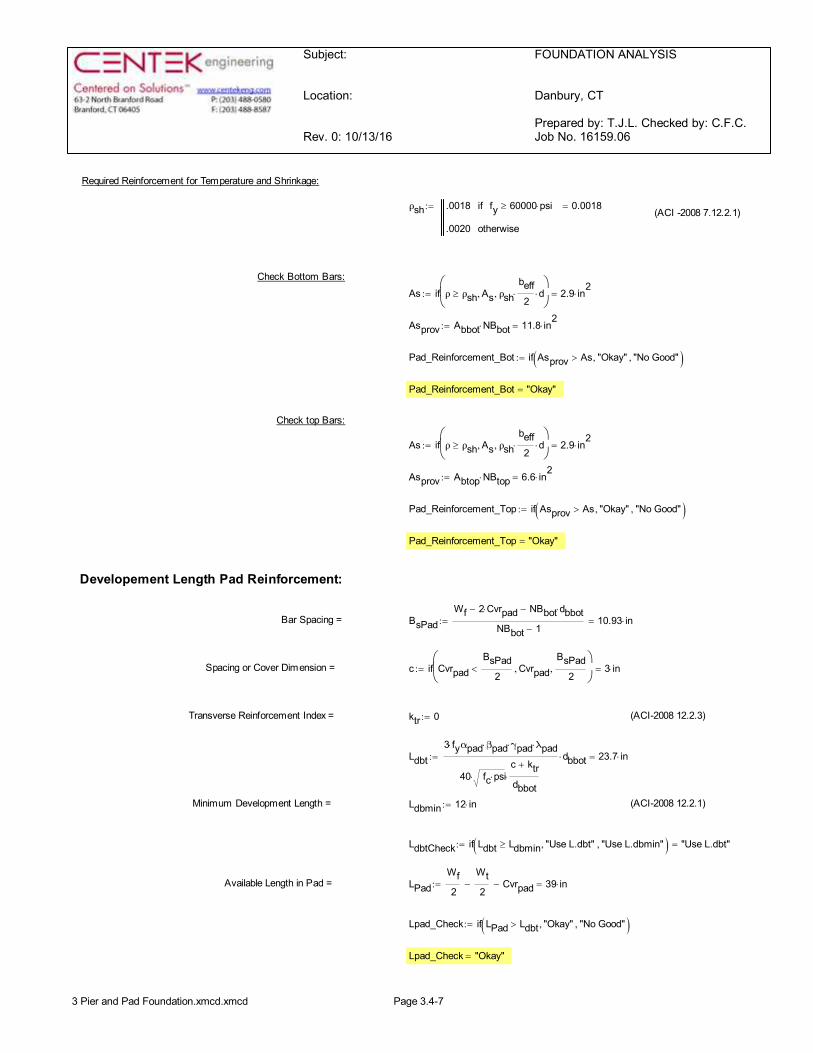
Required Reinforcement for Temperature and Shrinkage:
ρsh .0018 fy 60000 psi׳if
.0020 otherwise
0.0018=:=(ACI -2008 7.12.2.1)
Check Bottom Bars:As if ρ ρsh³ As, ρsh
beff2
× d×, æçè
ö÷ø
2.9 in2
×=:=
Asprov Abbot NBbot× 11.8 in2
×=:=
Pad_Reinforcement_Bot if Asprov As> "Okay", "No Good", ( ):=
Pad_Reinforcement_Bot "Okay"=
Check top Bars:
As if ρ ρsh³ As, ρshbeff2
× d×, æçè
ö÷ø
2.9 in2
×=:=
Asprov Abtop NBtop× 6.6 in2
×=:=
Pad_Reinforcement_Top if Asprov As> "Okay", "No Good", ( ):=
Pad_Reinforcement_Top "Okay"=
Developement Length Pad Reinforcement:
Bar Spacing = BsPadWf 2 Cvrpad×- NBbot dbbot×-
NBbot 1-10.93 in×=:=
Spacing or Cover Dimension = c if CvrpadBsPad
2< Cvrpad,
BsPad2
, æçè
ö÷ø
3 in×=:=
Transverse Reinforcement Index = ktr 0:= (ACI-2008 12.2.3)
Ldbt3 fy× αpad βpad× γpad× λpad×
40 fc psi××c ktr+
dbbot×
dbbot× 23.7 in×=:=
Minimum Development Length = Ldbmin 12 in×:= (ACI-2008 12.2.1)
LdbtCheck if Ldbt Ldbmin³ "Use L.dbt", "Use L.dbmin", ( ) "Use L.dbt"=:=
Available Length in Pad = LPadWf2
Wt2
- Cvrpad- 39 in×=:=
Lpad_Check if LPad Ldbt> "Okay", "No Good", ( ):=
Lpad_Check "Okay"=
3 Pier and Pad Foundation.xmcd.xmcd Page 3.4-7
Subject:
Location:
Rev. 0: 10/13/16
FOUNDATION ANALYSIS
Danbury, CT
Prepared by: T.J.L. Checked by: C.F.C.Job No. 16159.06
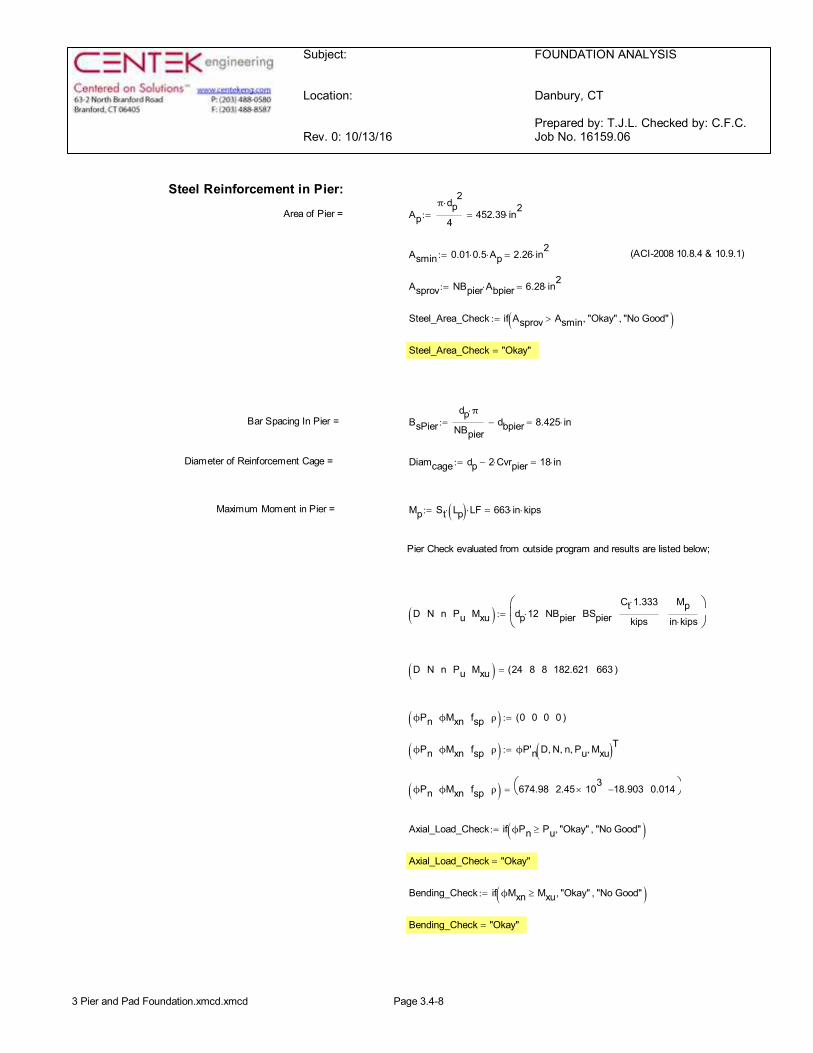
Steel Reinforcement in Pier:
Area of Pier = Apπ dp
2×
4452.39 in2
×=:=
Asmin 0.01 0.5× Ap× 2.26 in2×=:= (ACI-2008 10.8.4 & 10.9.1)
Asprov NBpier Abpier× 6.28 in2×=:=
Steel_Area_Check if Asprov Asmin> "Okay", "No Good", ( ):=
Steel_Area_Check "Okay"=
Bar Spacing In Pier = BsPierdp π×
NBpierdbpier- 8.425 in×=:=
Diameter of Reinforcement Cage = Diamcage dp 2 Cvrpier×- 18 in×=:=
Maximum Moment in Pier = Mp St Lp( )× LF× 663 in kips××=:=
Pier Check evaluated from outside program and results are listed below;
D N n Pu Mxu( ) dp 12× NBpier BSpierCt 1.333×
kips
Mpin kips×
æçè
ö÷ø
:=
D N n Pu Mxu( ) 24 8 8 182.621 663( )=
ϕPn ϕMxn fsp ρ( ) 0 0 0 0( ):=
ϕPn ϕMxn fsp ρ( ) ϕP'n D N, n, Pu, Mxu, ( )T:=
ϕPn ϕMxn fsp ρ( ) 674.98 2.45 103´ 18.903- 0.014æè öø=
Axial_Load_Check if ϕPn Pu³ "Okay", "No Good", ( ):=
Axial_Load_Check "Okay"=
Bending_Check if ϕMxn Mxu³ "Okay", "No Good", ( ):=
Bending_Check "Okay"=
3 Pier and Pad Foundation.xmcd.xmcd Page 3.4-8
Subject:
Location:
Rev. 0: 10/13/16
FOUNDATION ANALYSIS
Danbury, CT
Prepared by: T.J.L. Checked by: C.F.C.Job No. 16159.06
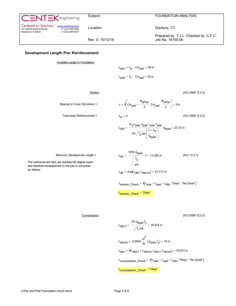
Development Length Pier Reinforcement:
Available Length in Foundation:
Lpier Lp Cvrpier- 48 in×=:=
Lpad Tf Cvrpad- 33 in×=:=
Tension: (ACI-2008 12.2.3)
Spacing or Cover Dimension = c if CvrpierBsPier
2< Cvrpier,
BsPier2
, æçè
ö÷ø
3 in×=:=
Transverse Reinforcement = ktr 0:= (ACI-2008 12.2.3)
Ldbt3 fy× αpier βpier× γpier× λpier×
40 fc psi××c ktr+
dbpier
æçè
ö÷ø
×
dbpier× 23.72 in×=:=
Minimum Development Length = Ldh1200 dbpier×
fcpsi
.7× 13.282 in×=:= (ACI 12.2.1)
Pier reinforcement bars are standard 90 degree hooksand therefore developement in the pad is computedas follows:
Ldb max Ldbt Ldbmin, ( ) 23.717 in×=:=
Ltension_Check if Lpier Lpad+ Ldbt> "Okay", "No Good", ( ):=
Ltension_Check "Okay"=
Compression: (ACI-2008 12.3.2)
Ldbc1.02 dbpier× fy×
fc psi×18.974 in×=:=
Ldbmin 0.0003in
2
lb× dbpier fy×( )× 18 in×=:=
Ldbc if Ldbc1 Ldbmin³ Ldbc1, Ldbmin, ( ) 18.974 in×=:=
Lcompression_Check if Lpier Lpad+ Ldbc> "Okay", "No Good", ( ):=
Lcompression_Check "Okay"=
3 Pier and Pad Foundation.xmcd.xmcd Page 3.4-9
Subject:
Location:
Rev. 0: 10/13/16
FOUNDATION ANALYSIS
Danbury, CT
Prepared by: T.J.L. Checked by: C.F.C.Job No. 16159.06
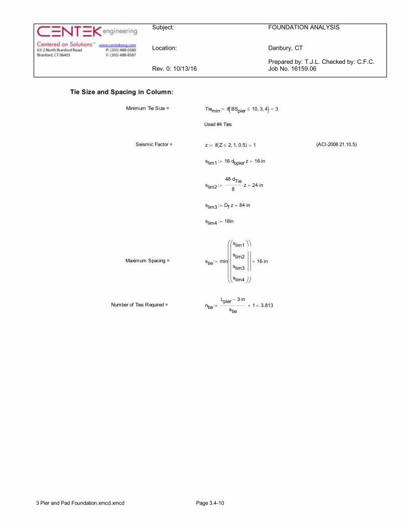
Tie Size and Spacing in Column:
Minimum Tie Size = Tiemin if BSpier 10£ 3, 4, ( ) 3=:=
Used #4 Ties
Seismic Factor = z if Z 2£ 1, 0.5, ( ) 1=:= (ACI-2008 21.10.5)
slim1 16 dbpier× z× 16 in×=:=
slim248 dTie×
8z× 24 in×=:=
slim3 Df z× 84 in×=:=
slim4 18in:=
Maximum Spacing = stie min
slim1
slim2
slim3
slim4
æçççççè
ö÷÷÷÷÷ø
æçççççè
ö÷÷÷÷÷ø
16 in×=:=
Number of Ties Required = ntieLpier 3 in×-
stie1+ 3.813=:=
3 Pier and Pad Foundation.xmcd.xmcd Page 3.4-10
9/26/2016 rfds.eng.tmobile.com/DataSheet/Printout/11436548
http://rfds.eng.tmobile.com/DataSheet/Printout/11436548 1/10
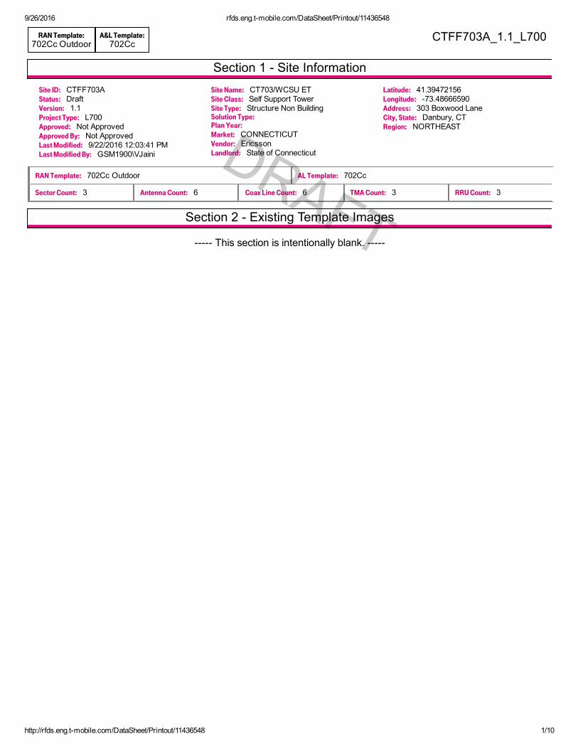
Section 1 Site Information
Section 2 Existing Template Images
RAN Template:702Cc Outdoor
A&L Template:702Cc
CTFF703A_1.1_L700
Site ID: CTFF703AStatus: DraftVersion: 1.1Project Type: L700Approved: Not ApprovedApproved By: Not ApprovedLast Modified: 9/22/2016 12:03:41 PMLast Modified By: GSM1900\VJaini
Site Name: CT703/WCSU ETSite Class: Self Support TowerSite Type: Structure Non BuildingSolution Type:Plan Year:Market: CONNECTICUTVendor: EricssonLandlord: State of Connecticut
Latitude: 41.39472156Longitude: 73.48666590Address: 303 Boxwood LaneCity, State: Danbury, CTRegion: NORTHEAST
RAN Template: 702Cc Outdoor AL Template: 702Cc
Sector Count: 3 Antenna Count: 6 Coax Line Count: 6 TMA Count: 3 RRU Count: 3
This section is intentionally blank.
DRAFT
DRAFT
9/26/2016 rfds.eng.tmobile.com/DataSheet/Printout/11436548
http://rfds.eng.tmobile.com/DataSheet/Printout/11436548 2/10
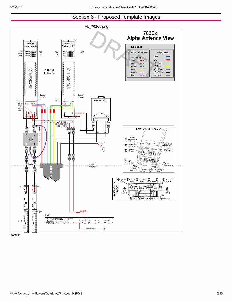
Section 3 Proposed Template Images
AL_702Cc.png
Notes:
DRAFT
DRAFT
9/26/2016 rfds.eng.tmobile.com/DataSheet/Printout/11436548
http://rfds.eng.tmobile.com/DataSheet/Printout/11436548 3/10
Section 4 Siteplan Images
This section is intentionally blank. DRAFT
DRAFT
9/26/2016 rfds.eng.tmobile.com/DataSheet/Printout/11436548
http://rfds.eng.tmobile.com/DataSheet/Printout/11436548 4/10
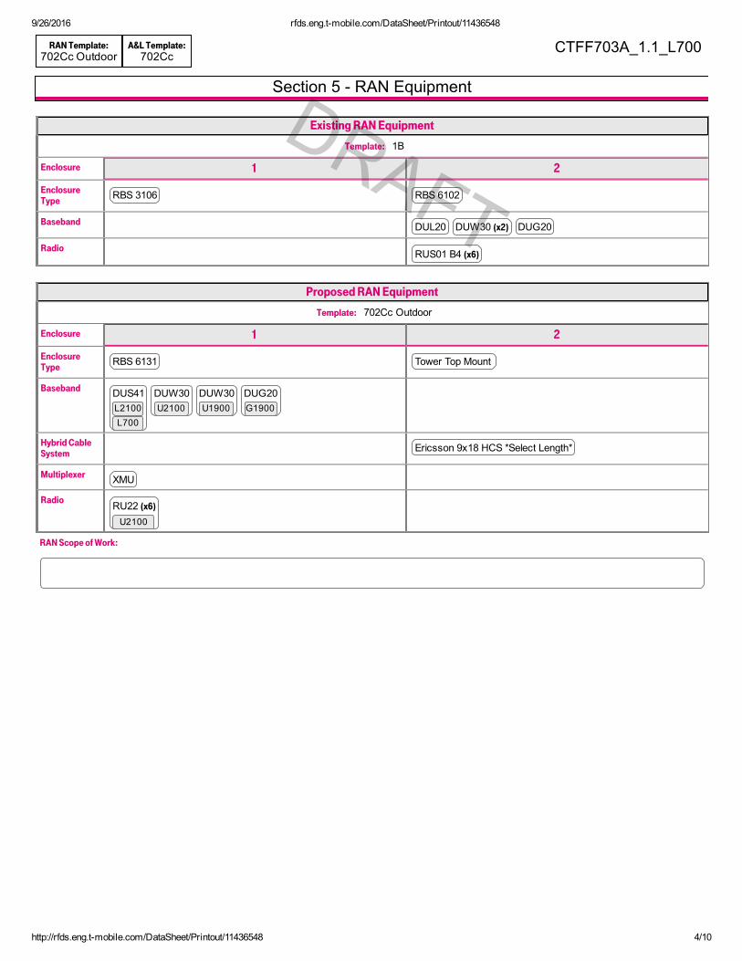
Section 5 RAN Equipment
RAN Template:702Cc Outdoor
A&L Template:702Cc
CTFF703A_1.1_L700
Existing RAN Equipment
Template: 1B
Enclosure 1 2
EnclosureType RBS 3106 RBS 6102
Baseband DUL20 DUW30 (x2) DUG20
Radio RUS01 B4 (x6)
Proposed RAN Equipment
Template: 702Cc Outdoor
Enclosure 1 2
EnclosureType RBS 6131 Tower Top Mount
Baseband DUS41 DUW30 DUW30 DUG20L2100L700
U2100 U1900 G1900
Hybrid CableSystem Ericsson 9x18 HCS *Select Length*
Multiplexer XMU
Radio RU22 (x6)
U2100
RAN Scope of Work:
DRAFT
DRAFT
9/26/2016 rfds.eng.tmobile.com/DataSheet/Printout/11436548
http://rfds.eng.tmobile.com/DataSheet/Printout/11436548 5/10
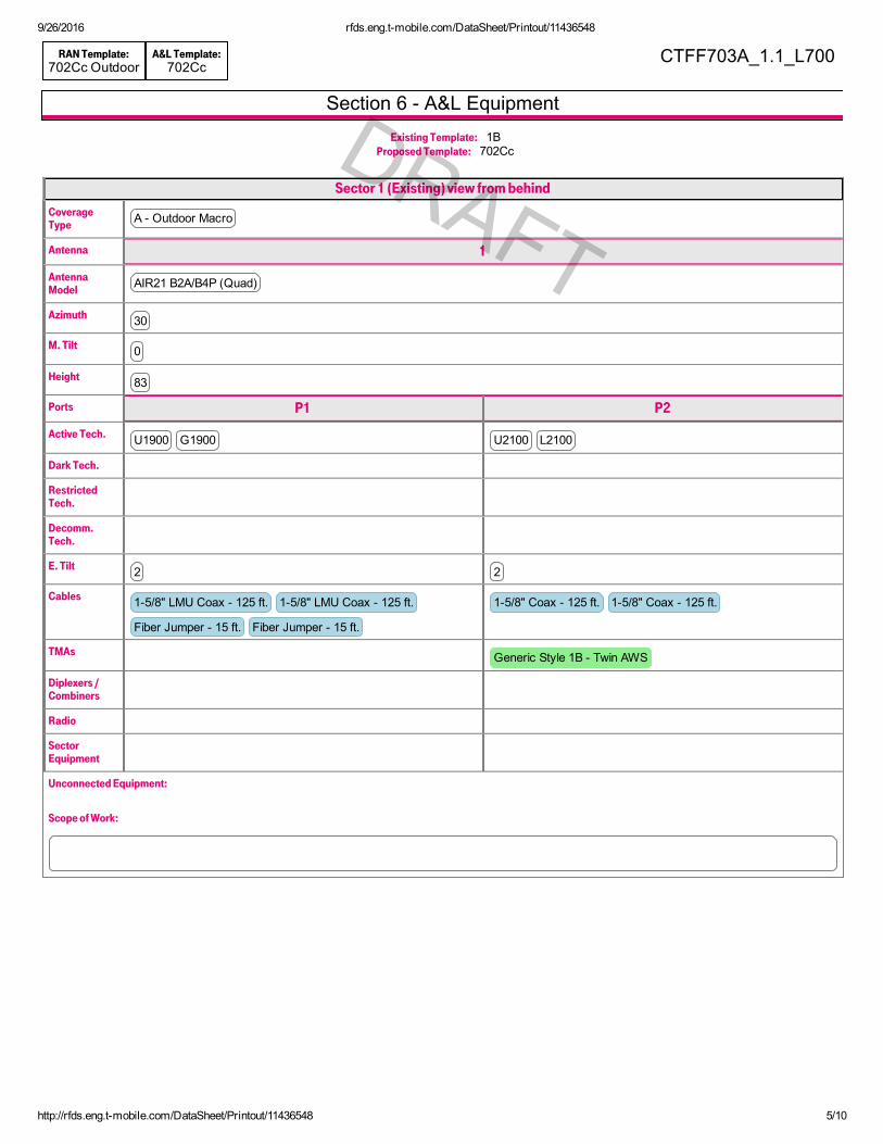
Section 6 A&L Equipment
RAN Template:702Cc Outdoor
A&L Template:702Cc
CTFF703A_1.1_L700
Existing Template: 1BProposed Template: 702Cc
Sector 1 (Existing) view from behind
CoverageType A Outdoor Macro
Antenna 1
AntennaModel AIR21 B2A/B4P (Quad)
Azimuth 30
M. Tilt 0
Height 83
Ports P1 P2
Active Tech. U1900 G1900 U2100 L2100
Dark Tech.
RestrictedTech.
Decomm.Tech.
E. Tilt 2 2
Cables 15/8" LMU Coax 125 ft. 15/8" LMU Coax 125 ft.
Fiber Jumper 15 ft. Fiber Jumper 15 ft.
15/8" Coax 125 ft. 15/8" Coax 125 ft.
TMAs Generic Style 1B Twin AWS
Diplexers /Combiners
Radio
SectorEquipment
Unconnected Equipment:
Scope of Work:
DRAFT

9/26/2016 rfds.eng.tmobile.com/DataSheet/Printout/11436548
http://rfds.eng.tmobile.com/DataSheet/Printout/11436548 6/10
RAN Template:702Cc Outdoor
A&L Template:702Cc
CTFF703A_1.1_L700
Sector 1 (Proposed) view from behind
CoverageType A Outdoor Macro
Antenna 1 2
AntennaModel AIR21 B2A/B4P (Quad) KRC 118 057/1 (Quad)
Azimuth 30 30
M. Tilt 0 0
Height 83 83
Ports P1 P2 P3 P4
Active Tech. U1900 G1900 U2100 L2100 L700
Dark Tech.
RestrictedTech.
Decomm.Tech.
E. Tilt 2 2 2 2
Cables 15/8" LMU Coax 125 ft.
15/8" LMU Coax 125 ft.
Fiber Jumper Fiber Jumper
15/8" Coax 125 ft.
15/8" Coax 125 ft.
Fiber Jumper Fiber Jumper Fiber Jumper Fiber Jumper
TMAs Generic Style 1B Twin AWS
Diplexers /Combiners
Radio RRUS11 B12
SectorEquipment
Unconnected Equipment:
Scope of Work:
9/26/2016 rfds.eng.tmobile.com/DataSheet/Printout/11436548
http://rfds.eng.tmobile.com/DataSheet/Printout/11436548 7/10
RAN Template:702Cc Outdoor
A&L Template:702Cc
CTFF703A_1.1_L700
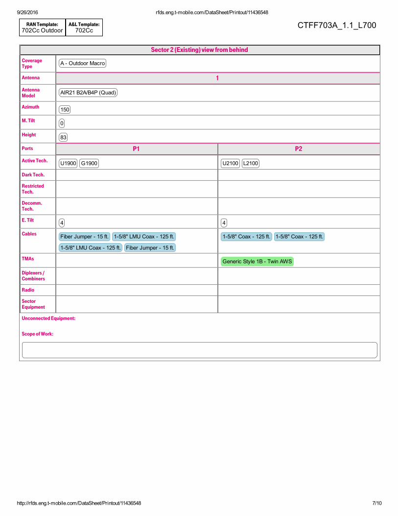
Sector 2 (Existing) view from behind
CoverageType A Outdoor Macro
Antenna 1
AntennaModel AIR21 B2A/B4P (Quad)
Azimuth 150
M. Tilt 0
Height 83
Ports P1 P2
Active Tech. U1900 G1900 U2100 L2100
Dark Tech.
RestrictedTech.
Decomm.Tech.
E. Tilt 4 4
Cables Fiber Jumper 15 ft. 15/8" LMU Coax 125 ft.
15/8" LMU Coax 125 ft. Fiber Jumper 15 ft.
15/8" Coax 125 ft. 15/8" Coax 125 ft.
TMAs Generic Style 1B Twin AWS
Diplexers /Combiners
Radio
SectorEquipment
Unconnected Equipment:
Scope of Work:
9/26/2016 rfds.eng.tmobile.com/DataSheet/Printout/11436548
http://rfds.eng.tmobile.com/DataSheet/Printout/11436548 8/10
RAN Template:702Cc Outdoor
A&L Template:702Cc
CTFF703A_1.1_L700
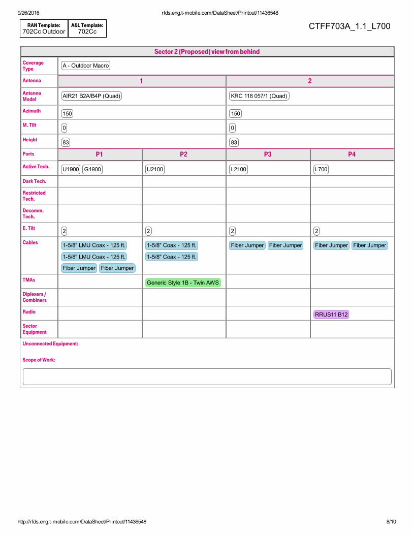
Sector 2 (Proposed) view from behind
CoverageType A Outdoor Macro
Antenna 1 2
AntennaModel AIR21 B2A/B4P (Quad) KRC 118 057/1 (Quad)
Azimuth 150 150
M. Tilt 0 0
Height 83 83
Ports P1 P2 P3 P4
Active Tech. U1900 G1900 U2100 L2100 L700
Dark Tech.
RestrictedTech.
Decomm.Tech.
E. Tilt 2 2 2 2
Cables 15/8" LMU Coax 125 ft.
15/8" LMU Coax 125 ft.
Fiber Jumper Fiber Jumper
15/8" Coax 125 ft.
15/8" Coax 125 ft.
Fiber Jumper Fiber Jumper Fiber Jumper Fiber Jumper
TMAs Generic Style 1B Twin AWS
Diplexers /Combiners
Radio RRUS11 B12
SectorEquipment
Unconnected Equipment:
Scope of Work:
9/26/2016 rfds.eng.tmobile.com/DataSheet/Printout/11436548
http://rfds.eng.tmobile.com/DataSheet/Printout/11436548 9/10
RAN Template:702Cc Outdoor
A&L Template:702Cc
CTFF703A_1.1_L700
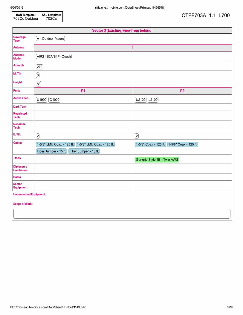
Sector 3 (Existing) view from behind
CoverageType A Outdoor Macro
Antenna 1
AntennaModel AIR21 B2A/B4P (Quad)
Azimuth 270
M. Tilt 0
Height 83
Ports P1 P2
Active Tech. U1900 G1900 U2100 L2100
Dark Tech.
RestrictedTech.
Decomm.Tech.
E. Tilt 2 2
Cables 15/8" LMU Coax 125 ft. 15/8" LMU Coax 125 ft.
Fiber Jumper 15 ft. Fiber Jumper 15 ft.
15/8" Coax 125 ft. 15/8" Coax 125 ft.
TMAs Generic Style 1B Twin AWS
Diplexers /Combiners
Radio
SectorEquipment
Unconnected Equipment:
Scope of Work:

9/26/2016 rfds.eng.tmobile.com/DataSheet/Printout/11436548
http://rfds.eng.tmobile.com/DataSheet/Printout/11436548 10/10
RAN Template:702Cc Outdoor
A&L Template:702Cc
CTFF703A_1.1_L700
Sector 3 (Proposed) view from behind
CoverageType A Outdoor Macro
Antenna 1 2
AntennaModel AIR21 B2A/B4P (Quad) KRC 118 057/1 (Quad)
Azimuth 270 270
M. Tilt 0 0
Height 83 83
Ports P1 P2 P3 P4
Active Tech. U1900 G1900 U2100 L2100 L700
Dark Tech.
RestrictedTech.
Decomm.Tech.
E. Tilt 2 2 2 2
Cables 15/8" LMU Coax 125 ft.
15/8" LMU Coax 125 ft.
Fiber Jumper Fiber Jumper
15/8" Coax 125 ft.
15/8" Coax 125 ft.
Fiber Jumper Fiber Jumper Fiber Jumper Fiber Jumper
TMAs Generic Style 1B Twin AWS
Diplexers /Combiners
Radio RRUS11 B12
SectorEquipment
Unconnected Equipment:
Scope of Work:
© 2010 AT&T Intellectual Property. All rights reserved. AT&T and the AT&T logo are trademarks of AT&T Intellectual Property.
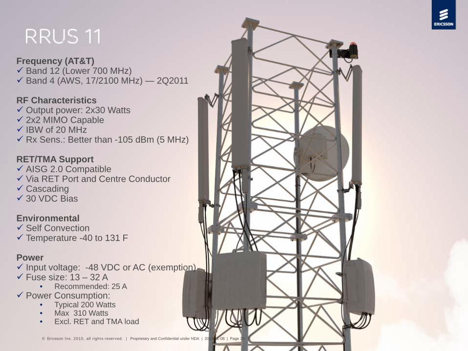
Frequency (AT&T)Band 12 (Lower 700 MHz)Band 4 (AWS, 17/2100 MHz) — 2Q2011
RF CharacteristicsOutput power: 2x30 Watts2x2 MIMO CapableIBW of 20 MHzRx Sens.: Better than -105 dBm (5 MHz)
RET/TMA SupportAISG 2.0 CompatibleVia RET Port and Centre ConductorCascading30 VDC Bias
EnvironmentalSelf ConvectionTemperature -40 to 131 F
PowerInput voltage: -48 VDC or AC (exemption)Fuse size: 13 – 32 A
• Recommended: 25 A
Power Consumption:• Typical 200 Watts• Max 310 Watts• Excl. RET and TMA load
© Ericsson Inc. 2010, all rights reserved. | Proprietary and Confidential under NDA | 2010-11-08 | Page 26
© 2010 AT&T Intellectual Property. All rights reserved. AT&T and the AT&T logo are trademarks of AT&T Intellectual Property.
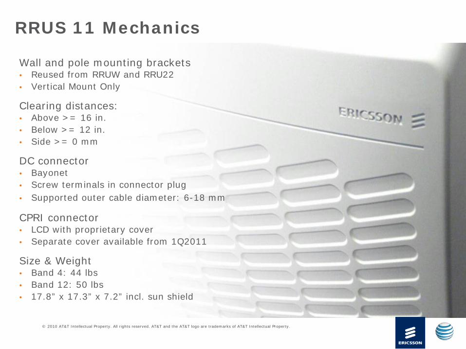
Wall and pole mounting brackets• Reused from RRUW and RRU22• Vertical Mount Only
Clearing distances:• Above >= 16 in.• Below >= 12 in.• Side >= 0 mm
DC connector• Bayonet• Screw terminals in connector plug• Supported outer cable diameter: 6-18 mm
CPRI connector• LCD with proprietary cover• Separate cover available from 1Q2011
Size & Weight • Band 4: 44 lbs• Band 12: 50 lbs• 17.8” x 17.3” x 7.2” incl. sun shield
RRUS 11 Mechanics
EBI Consulting environmental | engineering | due diligence
21 B Street . Burlington, MA 01803 . Tel: (781) 273.2500 . Fax: (781) 273.3311
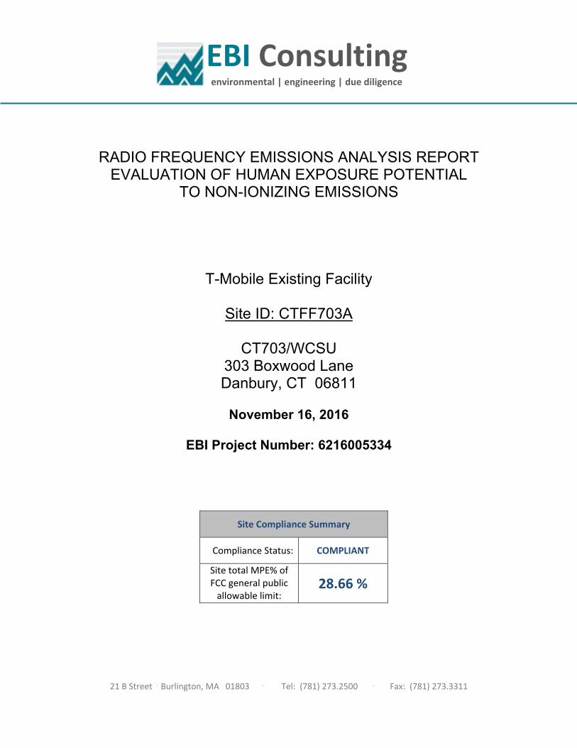
RADIO FREQUENCY EMISSIONS ANALYSIS REPORT EVALUATION OF HUMAN EXPOSURE POTENTIAL
TO NON-IONIZING EMISSIONS
T-Mobile Existing Facility
Site ID: CTFF703A
CT703/WCSU 303 Boxwood Lane Danbury, CT 06811
November 16, 2016
EBI Project Number: 6216005334
Site Compliance Summary
Compliance Status: COMPLIANT
Site total MPE% of FCC general public allowable limit:
28.66 %
EBI Consulting environmental | engineering | due diligence
21 B Street . Burlington, MA 01803 . Tel: (781) 273.2500 . Fax: (781) 273.3311
November 16, 2016
T-Mobile USA Attn: Jason Overbey, RF Manager 35 Griffin Road South Bloomfield, CT 06002
Emissions Analysis for Site: CTFF703A – CT703/WCSU
EBI Consulting was directed to analyze the proposed T-Mobile facility located at 303 Boxwood Lane, Danbury, CT, for the purpose of determining whether the emissions from the Proposed T-Mobile Antenna Installation located on this property are within specified federal limits.
All information used in this report was analyzed as a percentage of current Maximum Permissible Exposure (% MPE) as listed in the FCC OET Bulletin 65 Edition 97-01and ANSI/IEEE Std C95.1. The
FCC regulates Maximum Permissible Exposure in units of microwatts per square centimeter (W/cm2).
The number of W/cm2 calculated at each sample point is called the power density. The exposure limit for power density varies depending upon the frequencies being utilized. Wireless Carriers and Paging Services use different frequency bands each with different exposure limits, therefore it is necessary to report results and limits in terms of percent MPE rather than power density.
All results were compared to the FCC (Federal Communications Commission) radio frequency exposure rules, 47 CFR 1.1307(b)(1) – (b)(3), to determine compliance with the Maximum Permissible Exposure (MPE) limits for General Population/Uncontrolled environments as defined below.
General population/uncontrolled exposure limits apply to situations in which the general public may be exposed or in which persons who are exposed as a consequence of their employment may not be made fully aware of the potential for exposure or cannot exercise control over their exposure. Therefore, members of the general public would always be considered under this category when exposure is not employment related, for example, in the case of a telecommunications tower that exposes persons in a nearby residential area.
Public exposure to radio frequencies is regulated and enforced in units of microwatts per square centimeter (μW/cm2). The general population exposure limit for the 700 MHz Band is approximately 467 μW/cm2, and the general population exposure limit for the 1900 MHz (PCS) and 2100 MHz (AWS) bands is 1000 μW/cm2. Because each carrier will be using different frequency bands, and each frequency band has different exposure limits, it is necessary to report percent of MPE rather than power density.
EBI Consulting environmental | engineering | due diligence
21 B Street . Burlington, MA 01803 . Tel: (781) 273.2500 . Fax: (781) 273.3311
Occupational/controlled exposure limits apply to situations in which persons are exposed as a consequence of their employment and in which those persons who are exposed have been made fully aware of the potential for exposure and can exercise control over their exposure. Occupational/controlled exposure limits also apply where exposure is of a transient nature as a result of incidental passage through a location where exposure levels may be above general population/uncontrolled limits (see below), as long as the exposed person has been made fully aware of the potential for exposure and can exercise control over his or her exposure by leaving the area or by some other appropriate means.
Additional details can be found in FCC OET 65.
CALCULATIONS
Calculations were done for the proposed T-Mobile Wireless antenna facility located at 303 Boxwood Lane, Danbury, CT, using the equipment information listed below. All calculations were performed per the specifications under FCC OET 65. Since T-Mobile is proposing highly focused directional panel antennas, which project most of the emitted energy out toward the horizon, all calculations were performed assuming a lobe representing the maximum gain of the antenna per the antenna manufactures supplied specifications, minus 10 dB, was focused at the base of the tower. For this report the sample point is the top of a 6-foot person standing at the base of the tower.
For all calculations, all equipment was calculated using the following assumptions:
1) 2 GSM channels (PCS Band - 1900 MHz) were considered for each sector of the proposed installation. These Channels have a transmit power of 30 Watts per Channel.
2) 2 UMTS channels (PCS Band - 1900 MHz) were considered for each sector of the proposed installation. These Channels have a transmit power of 30 Watts per Channel.
3) 2 UMTS channels (AWS Band – 2100 MHz) were considered for each sector of the proposed installation. These Channels have a transmit power of 30 Watts per Channel.
4) 2 LTE channels (AWS Band – 2100 MHz) were considered for each sector of the proposed
installation. These Channels have a transmit power of 60 Watts per Channel 5) 1 LTE channel (700 MHz Band) was considered for each sector of the proposed installation.
This channel has a transmit power of 30 Watts.
EBI Consulting environmental | engineering | due diligence
21 B Street . Burlington, MA 01803 . Tel: (781) 273.2500 . Fax: (781) 273.3311
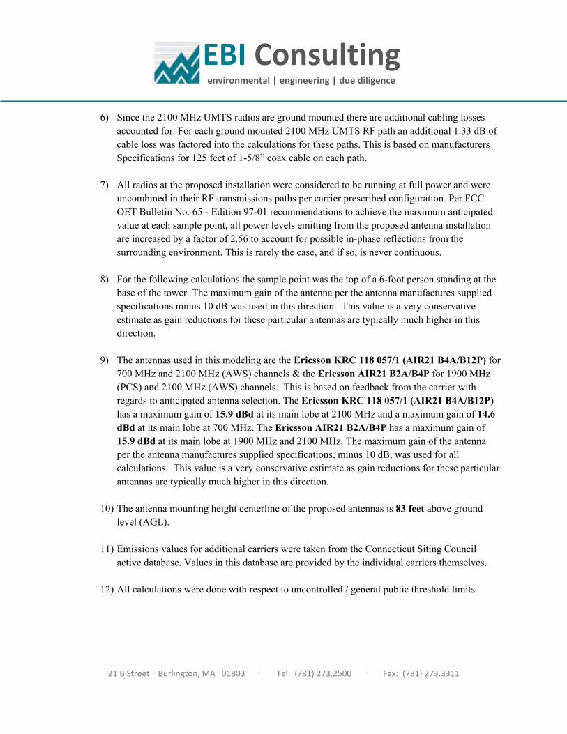
6) Since the 2100 MHz UMTS radios are ground mounted there are additional cabling losses accounted for. For each ground mounted 2100 MHz UMTS RF path an additional 1.33 dB of cable loss was factored into the calculations for these paths. This is based on manufacturers Specifications for 125 feet of 1-5/8” coax cable on each path.
7) All radios at the proposed installation were considered to be running at full power and were
uncombined in their RF transmissions paths per carrier prescribed configuration. Per FCC OET Bulletin No. 65 - Edition 97-01 recommendations to achieve the maximum anticipated value at each sample point, all power levels emitting from the proposed antenna installation are increased by a factor of 2.56 to account for possible in-phase reflections from the surrounding environment. This is rarely the case, and if so, is never continuous.
8) For the following calculations the sample point was the top of a 6-foot person standing at the base of the tower. The maximum gain of the antenna per the antenna manufactures supplied specifications minus 10 dB was used in this direction. This value is a very conservative estimate as gain reductions for these particular antennas are typically much higher in this direction.
9) The antennas used in this modeling are the Ericsson KRC 118 057/1 (AIR21 B4A/B12P) for 700 MHz and 2100 MHz (AWS) channels & the Ericsson AIR21 B2A/B4P for 1900 MHz (PCS) and 2100 MHz (AWS) channels. This is based on feedback from the carrier with regards to anticipated antenna selection. The Ericsson KRC 118 057/1 (AIR21 B4A/B12P) has a maximum gain of 15.9 dBd at its main lobe at 2100 MHz and a maximum gain of 14.6 dBd at its main lobe at 700 MHz. The Ericsson AIR21 B2A/B4P has a maximum gain of 15.9 dBd at its main lobe at 1900 MHz and 2100 MHz. The maximum gain of the antenna per the antenna manufactures supplied specifications, minus 10 dB, was used for all calculations. This value is a very conservative estimate as gain reductions for these particular antennas are typically much higher in this direction.
10) The antenna mounting height centerline of the proposed antennas is 83 feet above ground
level (AGL). 11) Emissions values for additional carriers were taken from the Connecticut Siting Council
active database. Values in this database are provided by the individual carriers themselves. 12) All calculations were done with respect to uncontrolled / general public threshold limits.
EBI Consulting environmental | engineering | due diligence
21 B Street . Burlington, MA 01803 . Tel: (781) 273.2500 . Fax: (781) 273.3311
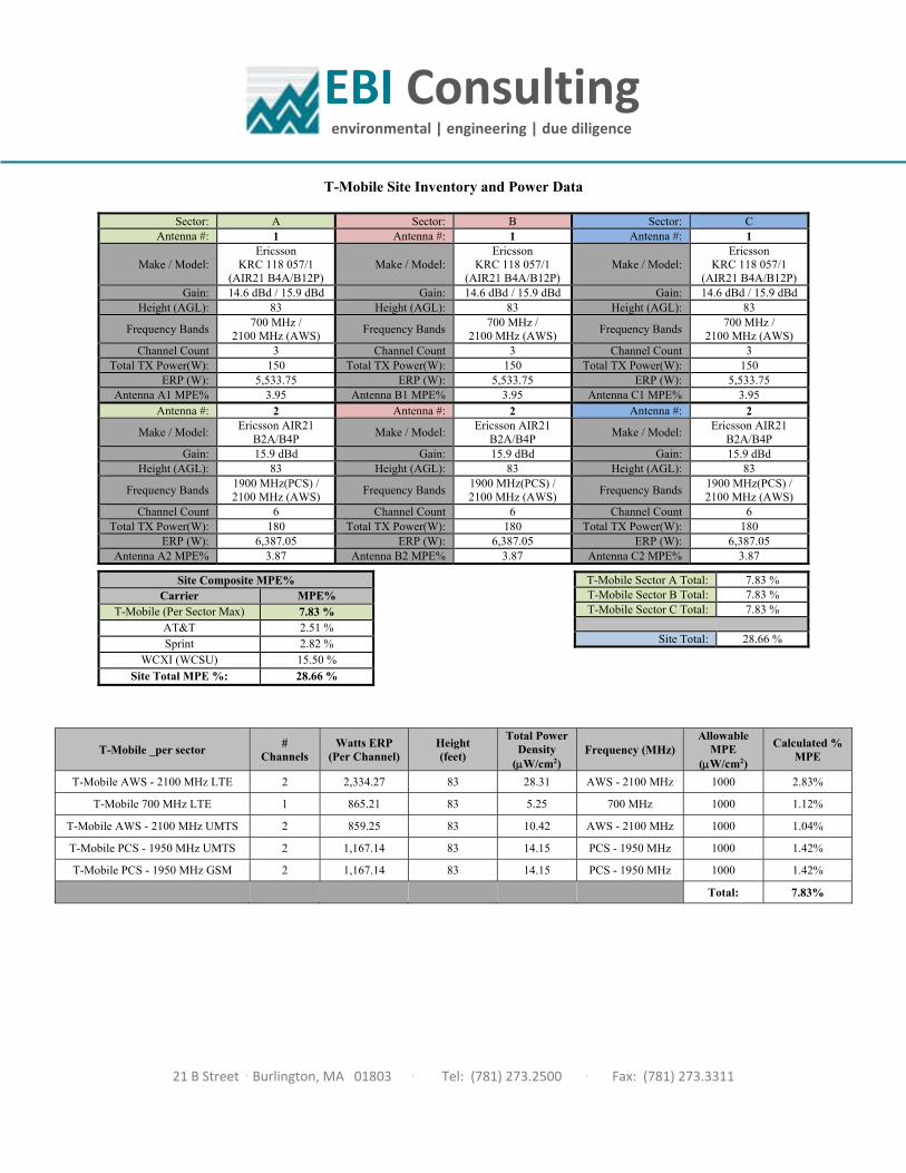
T-Mobile Site Inventory and Power Data
Sector: A Sector: B Sector: C Antenna #: 1 Antenna #: 1 Antenna #: 1
Make / Model: Ericsson
KRC 118 057/1 (AIR21 B4A/B12P)
Make / Model: Ericsson
KRC 118 057/1 (AIR21 B4A/B12P)
Make / Model: Ericsson
KRC 118 057/1 (AIR21 B4A/B12P)
Gain: 14.6 dBd / 15.9 dBd Gain: 14.6 dBd / 15.9 dBd Gain: 14.6 dBd / 15.9 dBd Height (AGL): 83 Height (AGL): 83 Height (AGL): 83
Frequency Bands 700 MHz /
2100 MHz (AWS) Frequency Bands
700 MHz / 2100 MHz (AWS)
Frequency Bands 700 MHz /
2100 MHz (AWS) Channel Count 3 Channel Count 3 Channel Count 3
Total TX Power(W): 150 Total TX Power(W): 150 Total TX Power(W): 150 ERP (W): 5,533.75 ERP (W): 5,533.75 ERP (W): 5,533.75
Antenna A1 MPE% 3.95 Antenna B1 MPE% 3.95 Antenna C1 MPE% 3.95 Antenna #: 2 Antenna #: 2 Antenna #: 2
Make / Model: Ericsson AIR21
B2A/B4P Make / Model:
Ericsson AIR21 B2A/B4P
Make / Model: Ericsson AIR21
B2A/B4P Gain: 15.9 dBd Gain: 15.9 dBd Gain: 15.9 dBd
Height (AGL): 83 Height (AGL): 83 Height (AGL): 83
Frequency Bands 1900 MHz(PCS) / 2100 MHz (AWS)
Frequency Bands 1900 MHz(PCS) / 2100 MHz (AWS)
Frequency Bands 1900 MHz(PCS) / 2100 MHz (AWS)
Channel Count 6 Channel Count 6 Channel Count 6 Total TX Power(W): 180 Total TX Power(W): 180 Total TX Power(W): 180
ERP (W): 6,387.05 ERP (W): 6,387.05 ERP (W): 6,387.05 Antenna A2 MPE% 3.87 Antenna B2 MPE% 3.87 Antenna C2 MPE% 3.87
T-Mobile Sector A Total: 7.83 % T-Mobile Sector B Total: 7.83 % T-Mobile Sector C Total: 7.83 %
Site Total: 28.66 %
Site Composite MPE% Carrier MPE%
T-Mobile (Per Sector Max) 7.83 % AT&T 2.51 % Sprint 2.82 %
WCXI (WCSU) 15.50 % Site Total MPE %: 28.66 %
T-Mobile _per sector #
Channels Watts ERP
(Per Channel) Height (feet)
Total Power Density
(W/cm2) Frequency (MHz)
Allowable MPE
(W/cm2)
Calculated % MPE
T-Mobile AWS - 2100 MHz LTE 2 2,334.27 83 28.31 AWS - 2100 MHz 1000 2.83%
T-Mobile 700 MHz LTE 1 865.21 83 5.25 700 MHz 1000 1.12%
T-Mobile AWS - 2100 MHz UMTS 2 859.25 83 10.42 AWS - 2100 MHz 1000 1.04%
T-Mobile PCS - 1950 MHz UMTS 2 1,167.14 83 14.15 PCS - 1950 MHz 1000 1.42%
T-Mobile PCS - 1950 MHz GSM 2 1,167.14 83 14.15 PCS - 1950 MHz 1000 1.42%
Total: 7.83%
EBI Consulting environmental | engineering | due diligence
21 B Street . Burlington, MA 01803 . Tel: (781) 273.2500 . Fax: (781) 273.3311
Summary
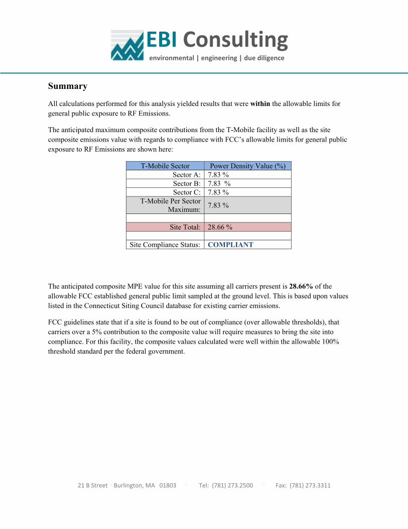
All calculations performed for this analysis yielded results that were within the allowable limits for general public exposure to RF Emissions.
The anticipated maximum composite contributions from the T-Mobile facility as well as the site composite emissions value with regards to compliance with FCC’s allowable limits for general public exposure to RF Emissions are shown here:
T-Mobile Sector Power Density Value (%) Sector A: 7.83 % Sector B: 7.83 % Sector C: 7.83 %
T-Mobile Per Sector Maximum:
7.83 %
Site Total: 28.66 %
Site Compliance Status: COMPLIANT
The anticipated composite MPE value for this site assuming all carriers present is 28.66% of the allowable FCC established general public limit sampled at the ground level. This is based upon values listed in the Connecticut Siting Council database for existing carrier emissions.
FCC guidelines state that if a site is found to be out of compliance (over allowable thresholds), that carriers over a 5% contribution to the composite value will require measures to bring the site into compliance. For this facility, the composite values calculated were well within the allowable 100% threshold standard per the federal government.