Embed Size (px)
Citation preview

AD-AI08 184 OKLAHOMA STATE UNIV STILLWATER ELECTRONICS LAB F/6 9/2AUTOMATED PCM ENCODER TEMPERATURE TEST, (U)AUG Al 1 W SPEARS F19628-8l-C-0079
UNCLASSIFIED SCIENTIFIC-b AFGL-TR-81-0242 NL
-~ 32
2I.8
Ml P() k W" T N T1 "1 lIARI

SLEVEL
.. i .l, ,J AFGL-TR- 81-0242
AUTOMATED PCM ENCODER TEMPERATURE TEST
J. W. Spears
Electronics Laboratory - D.E.T.A.Office of Engineering ResearchOklahoma State UniversityStillwater, Oklahoma 74078 D T IC
DEC 8 1981
15 August 1981 S
Scientific Report No. i B
Approved for public release; distribution unlimited.
AIR FORCE GEOPHYSICS LABORATORYAIR FORCE SYSTEMS COMMANDUNITED STATES AIR FORCEHANSCOM APB, MASSACHUSETTS 01731
81 12 08 232
$

Qualified requestors may obtain additional copies from theDefense Technical Information Center. All others shouldapply to the National Technical Information Service.
------------------------

UnclassifiedSECURITY CLASSIFICATION OF THIS PAGE (flhm Date Entered)
REPORT DOCUMENTATION PAGE READ INSTRUCTIONSBEFORE COMPLETING FORM
RE. APORT NUMBER 2. GOVT ACCESSION No.S3.RECPIENT'S CATALOG NUMBER
AFCL-SPRS-81-0242C-07
4. TITLE (nd Subtitle) A. TYPE OF REPORT & PERIOD COVEREDScientific Report No. 1AUTOMATED PCM ENCODER TEMPERATURE TEST I
6. PERFORMING ORG. REPORT NUMBER
7. AUT"NOR(a) S. CONTRACTO"R GRANT NUMBER(-')
J. W. SPEARS F19628-81-C-0079
S. PER FORMING ORGANIZATION "ME AND ADDRESS 10. PROGRAM ELEMENT. PROJECT, TASK
Electronics Laboratory/- D.E.T.A. AREA WORK UNIT NUMBERS
Oklahoma State University 62101FStillwater, Oklahoma 74078 765904BB
11. CONTROLLING OFFICE NAME AND ADDRESS 12. REPORT DATEAir Force Geophysics Laboratory 15 August 1981Hanscom AFB, Massachusetts 01731 13. NUMBER OF PAGES
Monitor/Jack R. Griffin/LCR 38
14. MONITORING AGENCY NAME & ADDRESS(I1 different from Controiling Office) 1S. SECURITY CLASS. (of this report)
UnclassifiedISa. DECLASSI FICATION/ DOWNGRADING
SCHEDULE
I6. DISTRIBUTION STATEMENT (of this Report)
Approved for public release; distribution unlimited.
17, DISTRIBUTION STATEMENT (of the abstract entered In Block 20, if different from Report)
IS. SUPPLEMENTARY NOTES
19. KEY WORDS (Continue on reverse side If necessary aid identify by block number)
Testing, Automated routines, PCM Encoding, Microprocessors
vi ABSTRACT (Continue on reverse aid* if necessary and Identify by block number)
This report describes an automated method for testing PCM encoder performancethrough use of microcomputer control and analysis of the test results. Themicrocomputer sequentially applies a known test input voltage to various inputsof the encoder under test, analyzes the digitally encoded signals from the en-coder for a large number of samples, and provides a printout of the test results.A description of computer software and interface hardware necessary for the test
is included.
DO I ,' 14 OEDITION OF I NOV SIS OBSOLETE ..ee@.,,s,v , -414t PAGE (When Date Sttered)

SECURITY CLASSIPICATION Of THIS PAGE(Uh'n Date galoerd)
SECURITY CLASSIFICATION OP THIS PAOEI3Miai Date Maltomi)

SUMMARY
Because of more stringent requirements for PCM encoder testing, an
automated system was developed to evaluate and provide a permanent record of
a PCM encoder's performance during temperature cycling. With this system, more
extensive testing may be done in less time than required for the previous methods
of encoder evaluation.
In the automated PCM encoder temperature test, a known voltage is applied
to the input of the system. A microcomputer is used to sequentially apply this
voltage to the various inputs of the encoder under test. The resultant digital
output from the encoder is then fed to an associated PCM decommutator. The
corresponding output signal from the PCM decommutator is then monitored by the
microcomputer, which provides hardcopy output by printing the binary bit pattern,
the calculated voltage, the error voltage (the difference between the calculated
encoder output and input voltages), and the number of samples taken at each
voltage level.
This report contains a description of the computer software and interface
hardware necessary to set-up and operate the temperature test on a PCM encoder.
Accession For
NTIS RA&IITr TABf
U.- nr0m u:ice d E! ~~~Ju "t i f C,1,til - - - - --
1Pt
CbutLion/-
PratlabilitY Codes
Avail and/orIL ~ i pval
I,

ACKNOWLEDGMENTS
The work discussed within this report was sponsored by the Aerospace
Instrumentation Division of the Air Force Geophysics Laboratory, Hanscom Air
Force Base, Massachusetts, under DOD contract F19628-78-C-0033 an4din the latest
applications, under DOD contract F19628-81-C-0079.
Gratitude is expressed to the contract monitor, Jack R. Griffin/LCR,
Sounding Rocket Branch, for the encouragement offered toward the work herein
reported.
Thanks are also expressed to Joe Zinn, Bill Holloway, and Brian Cloer who
were instrumental in the development of this automated test system.
2

TABLE OF CONTENTS
AUTOMATED PCM ENCODER TEMPERATURE TEST
Topic Page
1.0 Introduction .. .......................... 5
2.0 The Multiplex Breadboard. ................. .... 5
3.0 KIM Interface Box ................ ......... 8
4.0 Equipment for Test Setup. ...................... 8
5.0 Software .. ............................ 10
5.1 Machine Code Algorithm ZIPMC. .. .............. 10
5.1.1 Subroutine for Mainframe Data. .. .......... 10
5.1.2 Variables Used in ZIPMC. .. ............. 11
5.1.3 Subroutine for Subcom Data .. ............ 11
5.2 Basic Control Program .. ................... 13
5.2.1 Variables Used in ZIPB5. .............. 13
6.0 Running the Temperature Test ... ................ 15
7.0 Conclusions. .. .......................... 16
APPENDIX A
KIM Initialization For Temperature Test. ... .......... 19
APPENDIX B
Software Listings. ........................ 22
B.1 Basic Programs:
B.1.1 ZIPB5. .................. ........ 23
B.1.2 IRBS4. ................. ......... 26
B.1.3 FIRA . ............. ............. 28
B.1.4 SPRD4 .. .......................... 30
B.2 Assembler Programs:
B.2.1 ZIPA ............... ............ 32
B.2.2 ZIPAS. ................. ......... 34
B.2.3 SPRDA. ............... ........... 36
3

LIST OF ILLUSTRATIONS
*Figure No. Page
I IRiBS Temperature Test Block Diagram. ........... 6
2 FIRSSE Multiplex Breadboard. ............... 7
3 KIM Interf ace Box Schematic. ............... 9
4 Table for ZIPMC ........ ............. 11
5 Flowchart for ZIPMC ......... .......... 12
6 Example Printout of Temperature Test (FIRSSE). ..... 17
7 Example Printout of Temperature Test (Spread F). .. ... 18
4

1.0 Introduction
Once a new PCM encoder has been built, a normal requirement is environ-
mental testing. The automated test described here will check the encoder's:
1. Prime data and subcom data inputs for wiring errors during con-
struction.
2. Ability to convert analog to digital data within given specifi-
cations (normally ± LSB).
3. Characteristics during temperature cycles (00 to 65'C). (There
may be drift in the A/D in its full scale or zero offset, or most of all,
an IC failure. If an IC failure occurs, the chip is replaced and the en-
tire test repeated.)
4. Repeatability of sampled data.
5. Overall environmental noise level.
In the block diagram (Figure 1), the IRBS encoder is used as an example for
the test set up. The only things that vary from testing one encoder to another
are the "multiplex breadboard" and the software controlling the test.
The "multiplex breadboard" functions as a switching circuit, controlling
a precision analog input voltage, set by a null-reading voltmeter. The switching
circuit applies this voltage as an input signal to each encoder input line in a
predetermined sequence, controlled by the KIM microcomputer through a 6-bit
port on the KIM interface box. (This portion of the test set-up is a "bread-
board" because the analog data inputs vary from encoder to encoder.)
The output of the encoder is fed into an OSU PCM decommutator, which pro-
vides digital output in parallel words and their associated addresses. These
are monitored by the KIM through its interface box. Interaction between opera-
tor and computer is done through the CRT terminal. Once the test begins, it may
be monitored on the CRT and a hard copy is provided by the printer.
A DAC may be used to monitor particular PCM words during the test.
2.0 The Multiplex Breadboard
The FIRSSE breadboard provides an example of a two link system and its
"breadboard". HI-1818A chips are used here because of their low "on" resis-
tance (approximately 200 ohms) and high isolation between channels (80 db). In
Figure 2, the analog voltage is fed to all switching chips (IC 1-12) and the
computer controls their address lines. These IC's are enabled by signals from
two 3-to 8-line coders (IC's 13 & 14) and the "link enable" switch.
5

It, I
41I
ItI
"low* g EPR~UI 17 ~C DIAGRAM

OW W .'01" 1A/0 7*CS
JV6-ip 0 1*,6
42-4 - F 4 CAM& 3V r4, &MO
=LOL /,F -P /AIA /4
res 41-.Ir- 2
TI40444ad.C WZ'rgCARM
Yp' _6&_Yr AA,OTT f
&AAOFA ac A&
U.D
Figr* CA. =165MLTPE IUDO
TrT_ 7T 7

To help eliminate noise generated by the computer, it is essential to use
bypass capacitors on all power supplies and shielded wire for the address lines
from the computer.
The lowest address from the computer is 00. This should correspond to the
first minor frame word to be tested (in the FIRSSE encoder this is word 03 on
link 1 and word 08 on link 2). Then the address to the switching chips (from
the computer) should increase sequentially in accord with the main frame word
numbers on the encoder inputs. (Any alteration in this sequence creates more
software changes.)
3.0 KIM Interface Box
This unit enables the computer to read the parallel data from the decom
and to control the address lines to the "multiplex breadboard" which switches
the input signal. (Schematic in Figure 3).
The word clock period from the decom is lengthened to 1.5u sec by the
IC118 one-shot multivibrator. This is read by the computer through bit 7 of
the 74LS253 multiplexers at address 0403.
The word address lines are then read at address 0400 through the same
multiplexers. Once read, this address enables the data latches and the parallel
data is latched in at addresses 0401 and 0402. This interface enables the com-
puter to sample data at word rates up to 150 KHz.
Parallel data is also available at the buffered decom output for expansion
to other devices. The parallel data and word address lines are buffered.
4.0 Equipment for Test Setup.
When an automated temperature test is performed at the Oklahoma State
University Electronics Lab the following equipment is used:
Precision voltage source - EDC (RF-6146)
Precision voltmeter - Calibration Standards Corporation, Model
DC-1OOA (RF-6145)
Appropriate "multiplex breadboard" for input signal switching.
Any OSU PCM decoder (Models D90RPO, D90RP21, or D9ORFOI)
OSU KIM computer
Printer - Anadex DP-8000
CRT terminal - Hazeline 1500
KIM interface box
8

VIA
4 ~ *
sp4.
H. T 4-
.ZT 1 .......... ~
rumr
Pl~w S.KRAINTERFACE BOX SCHEMATIC

Monitor DAC (optional): OSU 8-channel or DAC processor
Power supplies ±l5v and +28v
Encoder to be tested
OSU temperature test chamber
5.0 Software
The software used to test an encoder is a combination of machine code and
BASIC programs. Together, these simplify obtaining data from the PCM decommu-
tator. The machine code program is a general purpose routine that may be used
for testing any PCM encoder. It requires the BASIC program to pass the output
word address (for subframe data, to pass both the word and frame address) be-
fore calling it.
The BASIC program controls the format of rhe words to be sampled, operator
data entry, and the data to the printer. This program is modified for each
encoder to be tested.
5.1 Machine Code Program ZIPMC
There are two parts to this program: ZIPA for mainframe data (begins at
address 7000) and ZIPAS for subcom data (begins at address 7100). These rou-
tines are identical, except the subcom routine monitors the subframe identifi-
cation to obtain the subcom data. For the SPREAD F encoder, the program SPDMC
uses SPRDA instead of ZIPAS for the subcom data selection.
5.1.1 Subroutine for Mainframe Data
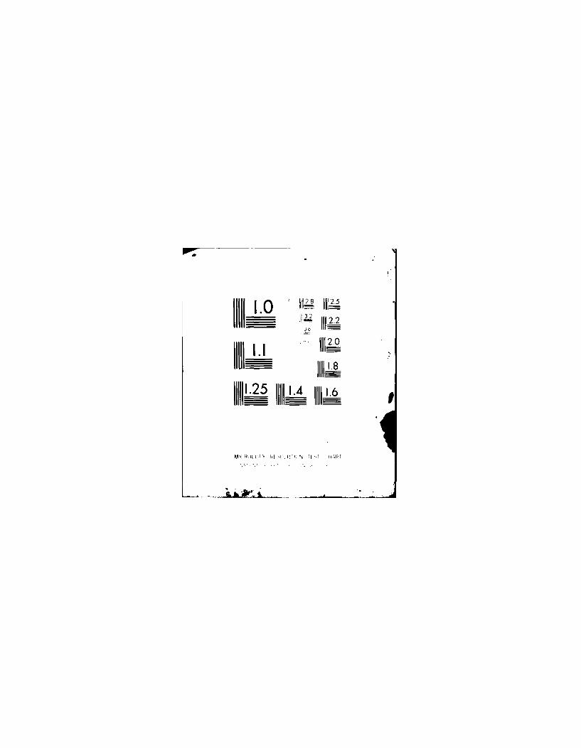
This subroutine samples the specified word, storing binary bit patterns
in array TABLE (Figure 4), counting the number of occurrences of each pattern.
Each different binary pattern is retained in TABLE at a new cell address. If
more than eight patterns are obtained, the data word is considered too noisy to
test and the program terminates. Otherwise, the program terminates with 10,000
samples of the specified word. A flow chart of this routine is in Figure 5.
The total number of samples may be changed at address 7010 (high byte) and
7015 (low byte) and must be in hexidecimal numbers. For this routine, the num-
ber of samples may vary from 1 to 65,536 (2 16).
10

Binary Data Number of Samples
Cell No. Address High Low High Low
I 7FCO
2 7FC4
3 7FC8
4 7FCC
5 7FDO
6 7FD4
7 7FD8
8 7FDC
Figure 4. TABLE FOR ZIPMC
5.1.2 Variables used in ZIPMC
X - Pointer to each address in TABLE.
Y - Cell pointer for next available address in TABLE to store binary data.
A - Obtains data from the interface box. The HEX addresses are:
0400 - decom word addresses.
0401 - decom data, bits 1-8 (MSBs), high binary data byte.
0402 - decom data, bits 9-16 (LSBs), low binary data byte.
0403 - decom word clock, positive pulse in bit 7.
TABLE - An array of 32 memory locations (addresses 7FCO through 7FDF initialized
to zero), divided into 8 cells of 4 locations each. The cells contain the
decom data (high and low bytes) obtained from the accumulator (A), and the
number of samples (high and low bytes) which is incremented when a sample
is taken.
7FBO - Up counter for low byte of number of the total samples. When equal to
low byte of samples, this location is set to zero.
7FBI - Location to save X so that X may be compared to Y.
7FB2, 7FB3 - Low and high bytes of the sample counter. Initialized to 10,000
(may be initialized to any number of samples), the low byte is compared to
7FBO with each sample taken. When equal, the high address (7FB3) is de-
cremented (if equal to zero the program terminates) and the low byte is set
to FF.
5.1.3 Subroutine for Subcom Data
The algorithm, flow chart, and variables are the same for this subroutine
11
ZCALO r" rAAiS
Ire say*
Va3V',,F
3.AdO vo
rAjr "r ve less
AfO
x
I
fsWoAlo Iva
Alla"m IVAS
40'esAT $VdPALA J"Dond ss ova
41AIArsps
Arrit DowMrAl. SAM4049.93 r fAe No jr
v-AA46dr
ours
Par JV/&,w oplTdc #v Orly'sZOSAS
xw X-01 I r r.4 Is ova 41
^&r r vo"ad S
SdovAr ItA*ArA lemp"a TWAAx
ro ^41
9,fA,*gAt&Av4FVr IrrX 09
J*A*APAX wlaw Arpdr PA,4 Lcp#v AwrrAr a.-
air "d 34ow Af a
Allo wax#,X 04 17 X a X 411'A orr, PAPVI-do- jf
Figure 6. FLOW GRANT FOR ZWOC
12
MORIN

as for the mainframe subroutine, except this routine obtains the subframe
identification before searching for the decom word address.
The routine assumes the ID is in word one, but may be modified by changing
address 712E (must use a hexidecimal number). The total number of samples is
100 (64 Hex) and may be changed at addresses 7115 (low byte) and 7110 (high byte).
The program scans the subframe ID, shifts it right 2 bits and compares this to
the frame number that BASIC stores at 714B. If an equal comparison, the pro-
grams scans for the decom word address (BASIC stores this at 714F), if not equal;
it continues to look for the correct ID.
For the various encoders that may be tested, the subframe ID may have to
be shifted or bits may have to be blanked to obtain an ID in a format that can
be compared to the desired frame number. The SPREAD F encoder subcom algorithm
is an example of software shifting the ID so that a comparison may be made.
This encoder's ID (word one) is in the most significant bits and is shifted
right four bits.
5.2 BASIC Control Program
This routine provides interaction between the operator and computer, passes
the word address and calls the machine code program, and then prints the results
after the return from the call. This routine is not general purpose and must be
modified for each encoder to be tested. Software listings for the ZIP, IRBS,
FIRSSE, and SPREAD F encoders are in Appendix B.
The BASIC control program for ZIP is an example that will be discussed; the
other programs in Appendix B are similar. The mainframe and subframe word ad-
dresses used are the main differences between the control programs.
For mainframe data, the ZIPB5 program samples words 12 through 43 (10,000
samples of each word) and samples selected subcom data from words 10 and 11 (100
samples of each subframe selected). In the program the variables are initialized,
data is obtained from the operator, the machine code program is executed, and
the data for each word sampled is printed.
5.3.1 Variables used in ZIPB5. (Program in Appendix B)
Numbers following variable are where variables initially occur. Section
to control mainframe data (statements 29-115):
DT$ - 29 Date of printout; should be manually changed to agree with current
date. The date is printed in the title.
13

N - 45 An array that contains selected subframe numbers. The dimension is
initialized to the total number of selected subframes. The selected sub-
frames are read from the data statements by the FOR/NEXT loop (47, 48, 50).
ST,ED - 56 Starting and ending mainframe word addresses.
A - 71 Current word addresses.
HX - 80 Used in conversion of a BCD number to hexidecimal. In statement 100,
HX is the converted nt, ber.
WA - 90 An intermediate variable used in conversion of a BCD number to hexi-
decimal.
8256, 8257 - 60, 65 Address locations to initialize the machine code subroutine
starting address. 8256 is the low address (0) and 8257 is the high address
(112 dec is 70 hex).
2048 - 72 Address location of KIM INTERFACE box output port. (2048 dec is
0800 hex).
28712 - 110 Address in machine code subroutine to store the current word ad-
dress (28712 dec is 7000 hex).
Subroutine to call machine code program and print results (statements 119-340):
J,XI - 119,120 The USR instruction requires this format but the variables are
not used.
M - 130 TABLE index. Initialized to 32704 dec (7FCO hex).
SM - 140 Low byte of the number of samples in TABLE.
SP - 153 High byte of the number of samples in TABLE.
B$- 170 String value to print the binary number in terms of l's and O's.
DA - 190 Obtains high and low bytes of the binary data to convert the data
to a string value (B$).
X - 195 Decimal value of each bit of the binary data.
FL - 270 Flag for loop indicator.
DI - 290 High binary data byte.
D2 - 300 Low binary data byte.
V - 310 Calculated voltage from binary data.
VO - 311 Intermediate value for calculated voltage.
VD - 315 Voltage difference between the calculated and input voltages (error
voltage).
Section to control subcom data (statements 350-610):
14

WD - 405 Subcom word number.
ST,ED - 410 Starting and ending loop values. Used to obtain a value from
array N.
K - 525 Current pointer to value in array N.
FR - 530 Current subframe number.
29007 - 520 Address location to initialize the word address in the machine
code program.
29003 - 570 Address location to store subframe number in machine code sub-
routine.
Other variables used in this section are similar to variables for the mainframe.
The list of selected subframe words is in the data statements 1000,1010.
The first data statement is for subcom word 10 and the second for subcom word
11.
Subroutine to obtain information from operator and to print the Heading
(1890-2100):
TI$ - 2000 Character string that is part of the title.
LI - 2007 Link number.
TP$ - 2010 Temperature of chamber. May be in degrees F or C.
VI - 2020 Input voltage (value from null reading volt meter).
TS$ - 2030 Used to move the output to the printer 5 spaces to the right.
T$ - 2040 Character string that is part of the title.
DL - 2080 Kim interface output port variable. The port is assigned this
value in statement 72.
6.0 Running the Temperature Test
To run the test the computer must be initialized (refer to KIM initiali-
zation in Appendix A), the equipment properly configured, and the PCM dpcommu-
tator placed in the "all words" mode.
The operator must select an input voltage on the precision voltage source
and null the voltmeter. If the computer has been initialized, the operator
should type in the appropriate date (set DT$ - "date"). Refer to the software
listing for the statement numbers and format for changing DT$. (In this mode
any line typed in must be followed by the return key to enter this information.)
When the temperature chamber has reached the test temperature and remained
there for 30 minutes (refer to"IRBS Acceptance Test Plan PCM Encoder Thermal
Cycling'for procedures concerning thermal cycling), the operator may type in:
15
h . . . .L . - i . . . . - , . _ .. . . - ' ' . . . . . . -.. . . i , ,-

RUN. The computer will print out the title and date, and then asks the operator
the link, temperature and the input voltage from the precision voltmeter. Refer
to Figures 6 and 7 for example printouts.
The computer will then print out the word number, its binary value, its
calculated voltage, the difference (error) between the calculated and the input
voltage, and the number of samples at each voltage level. Up to 10,000 total
samples are taken for each word (or only eight different voltage letels, which-
ever comes first).
If the subcom data is to be printed out (as in ZIP, SPREAD F, and IRBS),
it follows the same procedures as the main frame data except the number of samples
per word is reduced to 100 and the subcom word and frame numbers are written into
the software.
7.0 Conclusions
The automated testing of PCM encoders has greatly improved the speed and
quality of testing each unit. It allows more information to be gathered about
an encoder's characteristics and performance.
Data was repeatable at given voltage levels. Even though the test set up
actually introduced digital noise into the encoder during the test, the test
is still considered valid because no more than + 1 bit levels were observed (in
most of the data only + bit was observed).
16

FIRSSE TEMPERATURE CHECKS 4/10/81
LINK? 2TEMPERATURE? 28 CINPUT VOLTAGE? 5.0105
WORD* BINARY VALUE CALC VOLTAGE ERROR SAMPLES
8 11000000 00000000 5 -.0105 92568 11000000 00010000 5.00488 -5.62E-03 738a 10111111 11110000 4.99511 -,01539 6
0 10111111 11010000 4.98535 -.02515 74109 10111111 11100000 4*99043 -.02027 25859 10111111 11000000 4.98046 -.030o4 5
10 10111111 11010000 4,98535 -.02515 839410 10111111 11000000 4,9846 -.03004 1606
11 10111111 11100000 4.953 -.02027 616511 10111111 11110000 4.995t1 -.01539 3835
12 10111111 11100000 4,99023 -.02027 991212 10111111 11010000 4.98535 -,02515 6312 10111111 11110000 4.99511 -.01539 25
13 10111111 11100000 4.99023 -o02027 848413 10111111 11010000 4.98535 -,02515 1516
14 10111111 11010000 4o98535 -*02515 933514 10111111 11100000 4.99023 -.02027 66014 10111111 11000000 4.98046 -.03004 5
15 10111111 11100000 4.99023 -.02027 773515 10111111 11110000 4.995J1 -.01539 2265
16 10111111 11100000 4.99023 -o0227 970816 10111111 11110000 4,99511 -,01539 26916 10111111 11010000 4,98535 -,02515 23
17 10111111 11110000 4,99511 -0015J9 613
17 10111111 11100000 4o99023 -.02027 938517 10111111 11010000 4,98535 -o02515 2
18 10111111 11100000 4999023 -902027 755418 10111111 11010000 4.98535 -o02515 2446
19 10111111 11110000 4o99511 -o01539 969619 11000000 00000000 5 -00105 30019 10111111 11100000 4,99023 -.02027 4
Flgure 0. EXAMPLE PRINTOUT OF TEMPERATURE TEST
17

SPREAD F ENCODER TEMPERATURE CHECKIS 7/10/81
TEMPIRATURE? OCINPUT VOLTAGE? 4,499
WORD* BINARY VALUE CALC VOLTAGE ERROR SAMPLES
3 11100111 4.51171 .0127 9843 11100110 4.49218 -6.83E-03 53 11101000 4#53125 .03225 11
4 11100111 4,51171 .0127 9854 11101000 4.53125 .'3225 134 11100110 4,49218 -6.83E-03 2
5 11100111 4,51171 .0')27 9925 11100110 4.49218 -6.83E-03 - 55 11101000 4t!:-3125 t ()3225 3
6 11100111 4.51171 .0127 9876 11101000 4,53125 .03225 116 11100110 4.49218 -6.83E-03 2
7 11100111 4.51171 .0127 9847 11101000 4.53125 .03225 147 11100110 4.49218 -6.83E- .3 2
***N******* SUPFIRAME DATA *****i*****
WORD # 2TLMPLRATURE OCINPUT VOLTA;E 4,499
FRM# BINARY VALUE CALC VOLTAGE ERFOR SAMPLES
0 11100111 4#51171 .1 '-, 7 100
1 11100111 4.51171 .0127 100
2 11100111 4#51171 .0127 100
3 11100111 4.51171 .0127 1C
4 11100111 4.51171 .0127 100
5 11100111 4,51171 ,0127 100
6 11100111 4,51171 .0127 100
Figure 7. EXAMPLE PRINTOUT OF TEMPERATURE TEST
18t
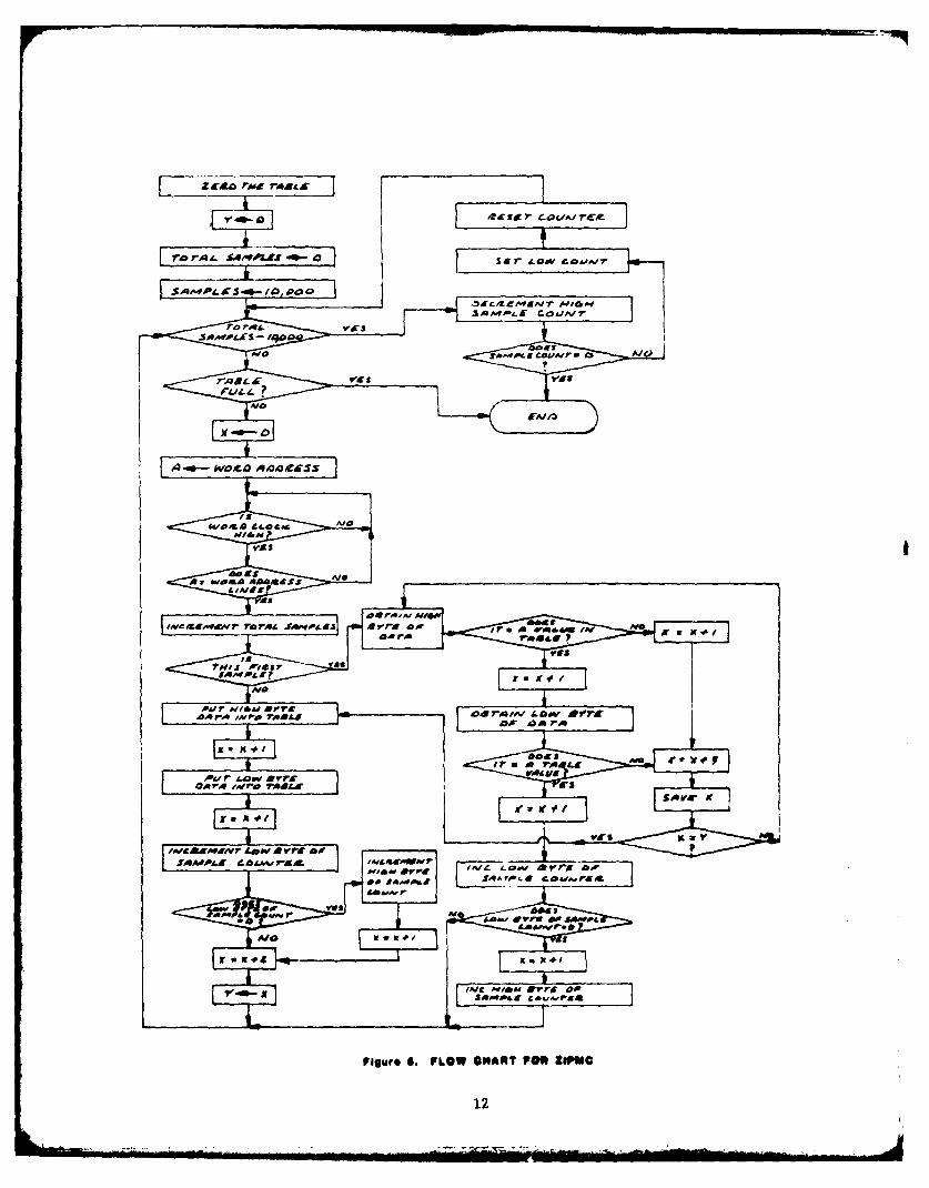
APPENDIX A
KIM INITIALIZATION FOR TEMPERATURE TEST
1. Turn on Hazeltine keyboard.
2. Turn on KIM computer.
Switch positions for computer
A. 1 MHzB. Halt (Down)C. NormalD. Reset (Momentarily lift up)
E. Printer interface set to inhibit
3. Hit return on keyboard
A. Computer should respond with "KIM
4. Type in: D400 FEE6 FF
5. Hit space bar:
A. Computer responds with D400 D8
6. Hit "G" key
7. KIM responds with "LMON"VIS11
8. Type in: MDC00, DCD0, 0000
9. Hit return
10. Hit return again (to get out of LMON mode)
A. KIM responds with "D400 D8"
11. Hit space bar
A. KIM responds with "0000 20"
12. Hit "G" key
13. Put in Disk #1B (FODS)
14. KIM responds "FODS"
15. Take out Disk #1B
16. Type in plus (+) sign (starts disk motor)
17. Put in Disk #1OB
18. KIM responds #
19. Type in the appropriate machine code program from Table 1. Example:
LOD %ZIPMC (Hit Return)
20. KIM responds #
21. Take out the Disk
22. Type in + sign.
19

rA23. Put in Disk #1B, Basic. (For use with Anadex printer)
24. KIM responds "#"
25. Type in: RUN %BASP
26. Hit Return
27. KIM responds: Type in:
# Of Lines/Page 0 (Hit Return)
Memory Size 28600 (Hit Return)
Terminal Width 80 (Hit Return)
28. Take disk out
29. Type in: Disk I (Hit return) (starts disk motor)
30. KIM responds: 'OK"
31. Put in Disk (Refer to Table I for appropriate program from Disk IOB.)
32. Type in: DISKL, name
33. Hit Return
34. KIM should respond with "OK"
35. Take Disk out
36. Type in: QUIT (Hit Return)
37. KIM responds: "#"
38. Hit "ESC" key and KIM responds: "0000 4C"
39. On computer front panel do the following:
A. Move HALT to up positionB. 2 MHzC. Move HALT to down positionD. Hit RESET
40. Hit return key on keyboard
41. KIM responds with "0000 4C"
42. Type in: 17F2 (Space Bar)
43. KIM should respond 17F2 0B
44. If KIM responds 17F2 0A then type in: 0B. (Make sure you type a periodafter 0B). This enters 0B into location 17F2 to set the baud rate betweenCRT and computer.
45. Hit the Space Bar
46. Hit "G" key
47. KIM should respond "OK."
48. Type in: RUN (Hit return to start program.) If the printer is to be used,
set printer interface switch to "HANDSHAKE".
20

TABLE 1 Programs are on Disk 10B.
Encoder under Program Name Machine CodeTest P rogr am
ZIP ZIPB5 ZIPMC
IRBS IRBS4 ZIPMC
FIRSSE FIRlA ZIPMC
SPREAD F SPRD4 SPDMC
*1 21

APPENDIX B
SOFTWARE LISTINGS
B.1 BASIC PROGRAMS:
B.1.1 ZIPB5
B.I.2 IRBS4
B.1..3 FIRIA
B.1.4 SPRD4
B.2 ASSEMBLER PROGRAMS:
B.2.1 ZIPA
B.2.2 ZIPAS
B.2.3 SPRDA
22

15 REM ZIPB5..,...ZIP-II ENCODER TEMPERATURE TEST16 REM20 REM THIS PROGRAM TAKES 10000 SAMPLES OF EACH MAINFRAME WORD21 REM AND 100 SAMP[.ES OF EACH SUBCOM WORD. WORDS 12 THRU 4322 REM ARE SAMPLED FIRST THEN THE SUBFRAME WORDS.23 REM THIS ROUTINE CALLS THE MACHINE CODE PROGRAM "ZIPMC"24 REM TO OBTAIN MAINFRAME AND SUBFRAME DATA.25 REM28 PRINT29 DT$="1/27/80"30 PRINT TAB(22);"ZIP-II TEMPERATURE TEST ";DT$35 PRINT : PRINT:40 PRINT43 REM ..... INITIALIZE ARRAY N FOR SUBFRAME DATA.....45 DIM N(25) : REM ...FOR THESE CHECKS# 25 SELECTED SUBCOM46 REM WORDS WILL 11E PRINTED.47 FOR 1=0 TO 2448 READ N(I)50 NEXT I55 GOSUB 2000 1 REM .... ,GET DATA FROM OPLRATOR...o.56 ST=12 a ED=43 c REM..,,.SET STARTING & ENDING MF WORD U'S58 REM .... INITIALIZE STARTING ADOR IOR ZIPMC59 REM THIS WILL READ MAINFRAME DATA60 POKE 8256,065 POKE 8257t11270 REM ..,..BEGIN LOOP FOR MAINFRAME DATA....71 FOR A=ST TO ED72 POKE 2048#DL73 DL=DL+I80 HX=INT(A/10)90 WA=A-(HX*1O)100 HX=HX*16+WA110 POKE 28712PHX111 GOSUB 119112 PRINT s NEXT A115 COTO 380117 REM ..... SUBROUTINE TO CALL MACHINE CODE PROGRAM118 REM AND PRINT RESULTS. (STATEMENTS 119-340)119 J=O120 XI=USR(J)130 M=32704140 SM=PEEK(M+2)153 SP=PEEK(M+3)155 IF SP+SM=O THEN RETURN160 FLwO170 B*=..190 DA-PEEK(M)195 X=128200 IF X(=DA THEN 230210 B$=B$+"O"220 GOTO 240230 B$=B$+'L"235 DA-DA-X240 X=X/2250 IF X)*5 THEN GOTO 200260 DA=PEEK(M+1)270 FLuFL+1275 B$=B$+...

280 IF FL=l THEN GOTO 195290 D1=PEEK(M)300 D2=PEEK(M+I)310 V=(D1+D2/256)/12.8311 VO=V312 SM=(SP*256)+SM313 V=INT((VO-10)*100000)/100000315 VD=V-VI316 VD=INT(VD,1 00000)/100000320 PRINT TS$;A;TAB(12);B$;TAB(34);V;TAB(50);VD;TAB(66);SM330 M=M+4340 GOTO 140345 REM350 REM .... *ROUTINE TO OBTAIN AND PRINT SUBCOM DATA....355 REM380 PRINT400 PRINT402 PRINT TS$;"************ SUBFRi-ME DATA ************"405 WD=1O410 ST=O . ED=15415 PRINT * PRINT420 PRINT TS$;"LINK ";LI435 PRINT TS$; "WORD # ";WD436 PRINT TS$;"TEMPERATURE ";TP$437 PRINT TS$+"INPUT VOLTAGE ";VI440 PRINT450 R$="FRM# BINARY VALUE CALC VOLTAGE ERROR460 PRINT TS$+R$+TI$478 POKE 8256,0480 POKE 8257,113490 HX=INT(WD/10)500 WA=WD-(HX*10)510 HX=HX*16+WA520 POKE 29007,HX525 FOR K=ST TO ED530 FR=N(K)535 PRINT550 HX=INT(FR/10)555 WA=FR-(HX*10)560 HX=HX*16t.WA570 POKE 29003,HX575 A=FR580 GOSLJB 119590 NEXT K595 IF K)24 THEN END60) ST=16 - ED=24610 WD=Ill GOTO 415900 REM910 REM ..... LIST OF SUBFRAME WORDS. FIRST DATA920 REM STATEMENT IS FOR SUBCOM WORD 10. THE930 REM SECOND IS FOR WORD 11.1000 DATA O,8,13, 16,24,32,37,41t48,565, s#64,69,72,80, 851010 DATA 16t24,32,40,60,68,72,80,871890 REM1900 REM ... SUBFROUTINE TO OBTAIN LINKTEMPERATURE, &£910 REM INPUT VOLTAGE FROM OPERATOR AND TO1920 REM PRINT DATA HEADING.1930 REM2000 TI$u" SAMPLES"2005 PRINT
24

2007 INPUT" LINKI*LI2010 INPUT " TEMPERATURE-ITP$2020 INPUT " INPUT VOLTAGE";VI2030 TSsz-2040 TS="WORI* BINARY VALUE CALl VOLTAGE ERROR2050 PRINT2060 PRINT TS$.T$+Ti$2070 PRINT2075 REM .....INITIALIZE DL (THE OUTPUT PORT VARIABLE)20130 IF LI~l THEN DL=:02090 IF 1II2 THEN r'L=322100 RETURN
OK
25

5 REM IRBS4o...#.IRBS ENCODER TEMPERATURE TEST6 REM10 REM THIS ROUTINE TAKES 10000 SAMPLES OF THE IRBS ENCODER20 REM ANALOG INPUTS FOR T1HE MAINFRAME DATA.25 REM26 REM THIS ROUTINE CALLS ZIF'MC TO OBTAIN DATA FROM THE27 REM DECOM. IT USES BOTH THE MAINFRAME AND SUBFAME28 REM ROUTINES OF ZIPMC. THE 'DATA' STATEMENTS DEFINE29 REM THE SELECTED SUBCOM WORDS.30 PRINT s PRINT35 DT$="7/10/80"37 PRINT TAB(24);"IRBS TEMPERATURE CHECKS ";DT$38 PRINT i PRINT45 OL=046 PRINT48 T1$=" SAMPLES"50 INPUT "TEMPERATURE";TP$51 INPUT "INPUT VOLTAGE";VI52 $T=5 : ED=3253 PRINT55 TS="WORD# BINARY VALUE CALC VOLTAGE ERROR56 PRINT T$+Tl$57 PRINT58 FOR A=ST tO ED60 POKE 8256.070 POKE 8257#11272 POKE 2048, DL73 DL=DL+l80 HX=INT(A/10)90 WA=A-(HX*10)100 HX=HX*16+WA110 POKE 28712,HX111 COSUB 119112 COTO 350119 J=O120 XI=USR(J)130 M=32704140 SM=PEEK(M+2)153 SP=PEEK(M+3)155 IF SP+SM=O THEN RETURN160 FL=O170 B$=""190 DA=FEEK(M)195 X=128200 IF X(=DA THEN 230210 B$=D$+"0"220 GOTO 240230 B$=B$+"1"235 DA=DA-X240 X=X/2250 IF X)#5 THEN GOTO 200260 DA=PEEK(M+L)270 FL=FL+1275 B$=B$."280 IF FLmI THEN GOTO 195290 DI=PEEK(M)300 D2"PEEK(M+I)310 V=(DI+D2/256)/51.2
26

311 VO=V312 SM=(SP*256)+SM313 V-INT((VO)*100000)/100000315 VD=V-VI316 VDmINT(VD*100000)/100000320 PRINT TAB(O);A;TAB(7);B$TAB(29),VTAB(45)IVD;TAB(61);SM330 M=M+4340 GOTO 140350 PRINT360 NEXT A370 IF ST-35 THEN GOTO 380371 ST=35 : ED=37372 GOTO 5B380 PRINT400 PRINT402 PRINT "***** SUBCOM DATA *****"403 PRINT404 DIM N(20)405 WD=33432 OR 1=1 TO 20433 READ N(I)434 NEXT I435 PRINT "WORD # "lWD436 PRINT "TEMPERATURE ";TP$437 PRINT "INPUT VOLTAGE ";VI440 R1$=" SAMPLES"450 R$="FRMU BINARY VALUE CALC VOLTAGE ERRORP460 PRINTsPRINT R$+RI$478 POKE 8256,0480 POKE 8257,113490 HX=INT(WD/10)500 WA=WD-(HX*10)510 HX-HX*16+WA518 F=1519 MX=10520 POKE 29007PHX525 IF WD=33 THEN GOTO 530526 F=11527 MX=17530 FOR K=F TO MX532 FR=N(K)535 PRINT540 HX=FR570 POKE 29003,HX575 AmFR580 GOSUB 119590 NEXT K595 PRINT596 PRINT599 IF WD34 THEN END600 DL-0609 WD=34610 GOTO 435700 DATA 2,9o IS26,34,42#49,58,66,74710 DATA 5#13.2129#37,45t53#58#66v74
OK
- 27
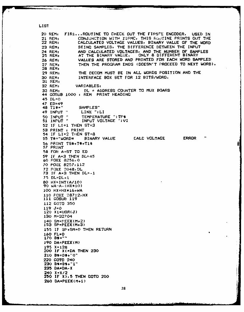
LIST
20 REMo FIR1...ROUTINE TO CHECK OUT THE FIRSFE ENCODER. USED IN21 REM: CONJUNCTION WITH ZIPMC, THIS RO'TINE PRINTS OUT THE22 REM: CALCULATED VOLTAGE VALUES# BINARY VALUE OF THE WORD
23 REMs BEING SAMPLED. THE DIFFERENCE BETWEEN THE INPUT24 REM# AND CALCULATED VOLTAGES# AND THE NUMBER OF SAMPLES25 REM. AT THE BINARY VALUE. ONLY 8 DIFFERENT BINARY26 REM. VALUES ARE STORED AND PRINTED FOR EACH WORD SAMPLED
27 REM, THEN THE PROGRAM ENDS (DOESN'T PROCEED TO NEXT WORD).28 REM.29 REMs THE DECOM MUST BE IN ALL WORDS POSITION AND THE30 REM- INTERFACE BOX SET FOR 12 BITS/WORD.31 REM:32 REM, VARIABLES33 REM; DL = ADDRESS COUNTER TO MUX BOARD44 COSUB 1000 : REM PRINT HEADING45 DL=O47 ED=4948 TX$=" SAMPLES"49 INPUT " LINK ";LI50 INPUT " TEMPERATURE ";TP$51 INPUT " INPUT VOLTAGE ";VI52 IF LI=I THEN ST=353 PRINT s PRINT54 IF LI=2 TiiEN ST:855 T$="WORD# BINARY VALUE CALC VOLTAGE ERROR
56 PRINT TS$+T$+T1$57 PRINT58 FOR A=ST TO ED
59 IF A=3 THEN DL=4560 POKE 8256,070 POICE 8257.11272 POKE 2048,DL73 IF A=3 THEN DL=-175 DL=DL+l80 HX=INT(A/10)90 WAzA-(HX*10)100 HX=HX*16+WA110 POKE 28712,HX111 COSUB 119112 COTO 350119 J=O120 XI=USR(J)
130 M=32704140 SM=FEEK(M+2)153 SP=PEEK(M+3)
155 IF SP SM=O THEN RETURN160 FL=O170 B$:s..190 DA=PEEK(M)195 X=128200 IF X(-DA THEN 230210 BS=D$+"O"220 GOTO 240230 BI=B$+"1"235 DAwDA-X240 X=X/2250 IF X),5 THEN GOTO 200260 DA=PEEK(M+1)
28

270 FL=FL+I27.5 8$=B$+"280 IF FL=l THEN COTO 195290 Dl=PEEK(M)300 D2=PEEK(M+l)310 V=(DI+D2/256)/12.8311 VO=V312 SM=(SP*256)+SM313 V=INT((VO-10)*100000)/100000315 VD=V-VI316 VD=INT(VD*l00000)/100000320 PRINT TAB(6);A;TAB(12);B$;TAB(34)IV;TAB(50);VDTAB(66);SM330 M=M+4340 COTO 140350 PRINT
355 IF A=3 THEN A=4360 NEXT A
370 POKE 2048,00440 IF LI=2 THEN END450 PRINT550 INPUT IS LINK 2 READY (Y=YES)";Y$
560 IF Y$="Y" THEN GOTO 590570 END590 IF LI=1 THEN LI=2595 PRINT a PRINT598 PRINT " LINK ?"3 LI600 PRINT TEMPERATURE ?"; TP$605 PRINT " INPUT VOLTAGE ?";VI608 DL=O610 COTO 521000 DT$="4/10/81"1010 TS$="1020 PRINT i PRINT s PRINT1030 PRINT TAB(20);"FIRSSE ENCOI:ER TEMPERATURE TEST ";DT$1040 PRINT PRINT PRINT1050 RETURN
OK
29

15 REM SPRD4...........SPREAD F ENCODER TEMPERATURE TEST16 REM20 REM THIS PROGRAM TAKES 1000 SAMPLES OF EACH MAINFRAME WORD21 REM AND 100 SAMPLES OF EACH SUBCOM WORD. WORDS 3 THRU 722 REM ARE SAMPLED FIRST THEN THE SUBFRAME WORDS.23 REM THIS ROUTINE CALLS THE MACHINE CODE PROGRAM "SPDMC"24 REM TO OBTAIN MAINFRAME AND SUBFRAME DATA.25 REM26 REM THIS PROGRAM DOES NOT PRINT THE PARITY BIT (BIT 9).27 REM
28 PRINT29 DT$="7/8/81"30 PRINT TAB(18);"SPREAD F ENCODER TEMPERATURE CHECKS ";DT$: PRINT PRIt40 PRINT42 DL=843 REM ..... INITIALIZE ARRAY N FOR SUBFRAME DATA.....45 DIM N(16)47 FOR I=0 TO 1548 READ N(I)50 NEXT I55 GOSUB 2000 REM ..... GET DATA FROM OPERATOR.....56 ST=3 : ED=7 REM.....SET STARTING & ENDING MF WORD S58 REM ..... INITIALIZE STARTING ADDR FOR SPDMC.,....59 REM THIS WILL READ MAINFRAME DATA60 POKE 8256,065 POKE 8257,11270 REM *.*,,BEGIN LOOP FOR MAINFRAME DATA..,..71 FOR A=ST TO ED72 POKE 2048,rrL73 DL=DL+180 HX=INT(A/10)90 WA=A-(IHX*10)100 HXuHX*16+WA110 POKE 28712,HX111 GOSUB 119112 PRINT i NEXT A115 GOTO 380117 REM ..... SUBROUTINE TO CALL MACHINE CODE PROGRAM118 REM AND FRINT RESULTS. (STATEMENTS 119-340)119 J=O120 XI=USR(J) i REM .o..CALL MACHINE CODE PROGRAM....130 M=32704140 SM=PEEK(M+2)153 SP=PEEK(M+3)155 IF SP+SM=0 THEN RETURN160 FL=O170 B$=190 DA=PEEK(M)195 X=128200 IF X(=DA THEN 230210 BS=B$+"O"220 GOTO 240230 B$=B$+"I"235 DA=DA-X240 X&X/2250 IF X).5 THEN GOTO 200260 DA-PEEK(M+I)290 DI=PEEK(M)
30

300 D2=PEEK(M+I)310 V=(DI+D2/256)/51.2311 VOmV312 SM=(SP*256)+SM313 V=INT((VO)*100000)/100000315 VD=V-VI316 VD=INT(VD*100000)/100000320 PRINT TS$;A;TAB(16);B$;TAB(34);V;TAB(50);VD;TAB(66);SM330 M=M+4340 GOTO 140345 REM350 REM .....ROUTINE TO OBTAIN AND PRINT SUBCOM DATA....355 REM380 PRINT400 PRINT402 PRINT TS$;"************ SUBFRAME DATA ************"403 PRINT405 WD=2435 PRINT TS$I"WORD * ";WD436 PRINT TS$;"TEMPERATURE ";TP$437 PRINT TS$+"INPUT VOLTAGE ";VI450 R$="FRM* BINARY VALUE CALC VOLTAGE ERROR460 PRINT s PRINT TS$+R$+T1$478 POKE 825690480 POKE 8257,113490 HX=INT(WD/10)500 WA=WD-(HX*10)510 HX=HX*16+WA520 POKE 29000,HX525 FOR FR=O TO 15530 DL=N(FR)535 PRINT545 POKE 2048,DL570 POKE 28996, FR575 A=FR580 GOSUB 119590 NEXT FR600 DL=8610 END900 REM910 REM ... ,DATA TO CONTROL MUX BREADBOARD920 REM TO OBTAIN SJBFRAME DATA....930 REM1000 DATA 13,14.15t16,13.17,18.19,13.14.15,16,13,20,21,221890 REM1900 REM .***SUBROUTINE TO OBTAIN TEMPERATURE AND1910 REM INPUT VOLTAGE FROM OPERATOR AND TO1920 REM PRINT DATA HEADING.1930 REM2000 T1$*"" SAMPLES"2005 PRINT2010 INPUT " TEMPERATURE"ITP$2020 INPUT INPUT VOLTAGE"iVI2030 TS*-"2040 T$-"WORDO BINARY VALUE CALC VOLTAGE ERROR2050 PRINT2060 PRINT T6S+T$+TI$2070 PRINT2080 RETURN
OK
31

10 0000 ZIPA..... .FOR MAIN FRAME DATA20 000030 0000 ; 6/30/8040 000050 0000 ; ZIPMC IS THE MACHINE CODE FORM OF THIS PROGRAM.60 000070 0000 380 0000 ; SUBROUTINE TO BE USED IN CONJUNCTION WITH BASIC90 0000 ; TO LOOK AT DATA FROM THE DECOM....USE WITH ZIPB..100 0000110 0000 ; THIS ROUTINE SAMPLES A WORD 10,000 TIMES AND120 0000 ; COUNTS THE # OF WORDS THAT ARE A LIKE. THERE130 0000 * ARE ONLY 8 DIFFERENT BET PATTERNS RETAINED.140 0000150 7000 *=$7000160 7000 TABLE =$7FC0170 7000180 7000 A240 ZIPA LOX #$40 * ZERO THE TABLE190 7002 A900 I.DA #0200 7004 9DBF7F LOOPA STA $7FBF,X210 7007 CA DEX220 7008 DOFA BNE LOOPA230 700A AOOO LDY #0240 700C 8CBO7F STY $7FB0 ; TOTAL SAMPLES=O250 700F A927 LOA #$27 SET HI BYTE OF a OF SAMPLES260 7011 8DB37F STA $7FB3270 7014 A937 LDA #$37 ; SET i.0W BYTE OF a OF SAMPLES280 7016 8DB27F STA $7F[2290 7019 ADS27F TSAM LDA $7FB2 ; GET # OF SAMPLES300 701C CDBO7F CMP $7FDO310 701F F066 BED CKSAM320 7021 C020 NOISE CPY #$20 ; IF=20 THEN "ITS REAL NOISY!!"330 7023 F067 BEG END340 7025 A200 TABPT LOX #$00 ; SET TABLE POINTER=O350 7027 A900 LDA #$00 ; GET WORD 0 FROM BASIC360 7029 2C0304 WDCIK BIT $403 ; IS WORID CLOCK HI?370 702C 10FB BDPL WDCI-K380 702E CDOO04 LOOF'B CMP $400 ; GET WORD ADDRESS390 7031 DOF6 ENE WDCLK400 7033 EEBO7F INC $7FBO ; INC THE TOTAL SAMPLES410 7036 COO CPY .00 ; IS THIS FIRST SAMPLE420 7038 DOlE BNE NEWDAT430 703A ADo104 GETHI LDA $401 ; GET HI DATA (M 3B'S)440 703D 90C07F STA TABLEX ; PUT INTO TABLE450 7040 ES INX460 7041 AD0204 LDA $402 ; GET LOW DATA470 7044 9DCO7F ETA TABLEX480 7047 ES INX490 7048 FECO7F INC TABLEPX ; INC* SAMPLES FOR THIS DATA500 704B O05 BNE XPLUS u IF LO CNT=O THEN INC HI CNT510 7040 E8 INX520 704L FECO7F INC TABLFX INC HI CNT530 7051 CA DEX540 7052 ES XPLOIS INX550 7053 Ea INX560 7054 BA TXA ! SET Y=X570 7055 AS TAY580 7056 10CI BPL TSAM GO CHECK TOTAL SAMPLES
32

590 7058 AD0104 NEWDAT I.DA $401 ; GET HI DATA600 705B DDC07F CMP TABLEX ; = TO TABLE VALUE?610 705E FOOE BEQ TESTLO620 7060 ES SETX3 INX f XwX+4
630 7061 E8 SETX2 INX640 7062 ES INX650 7063 E8 INX660 7064 8EB17F STX $7FBI ; SAVE X TO CMP670 7067 CCB17F CPY $7FB1 ; DOES X=Y??680 706A DOEC BNE NEWDAT ; GO GET NEXT TABLE VALUE690 706C FOCC BEG GETHI ; GO PUT INTO TABLE700 706E ES TESTLO INX710 706F ADO204 LDA $402 ; GET LOW DATA720 7072 DDCO7F CMP TABLEX ; = TO TABLE VALUE?730 7075 DOEA BNE SETX2740 7077 ES INX750 7078 FECO7F INC TABLEX ; INC THE SAMPLE CNT760 707B F003 BEG HISAM ; IF=C' THEN INC HI SAMPLE CNT770 7070 4C1970 JMP TSAM780 7080 E8 HISAM INX790 7081 FECO7F INC TABLE,X ; INC HI SAM CNT800 7084 4C1970 JMP TSAM810 7087 CEB37F CKSAM DEC $7FB3 ; DEC HI SAMPLE CNT820 708A 1001 BPL SETLO830 708C 60 END RTS840 708D A9FF SETLO LDA #$FF ; SET LO CNT850 708F 8DB27F STA $7FB2860 7092 A900 LDA #$00 ; RESET CNT870 7094 8DB07F STA $7FBO880 7097 4C1970 JMP TSAM
33

10 0000 ; ZIPAS.,.....ROUTINE TO OJBTAIN SUBCOM DATA20 000030 0000 ; 6/30/8040 00005) 0000 ; SUBROUTINE TO BE USED IN CONJUNCTION WITH BASIC60 0000 ; TO LOOK AT DATA FROM THE DECOM,...USE WITH ZIPB..70 000080 0000 ; THIS ROUTINE SAMPLES A SUBCOM WORD 100 TIMES AND90 0000 ; COUNTS THE * OF WORDS THAT ARE A LIKE. THERE100 0000 ; ARE ONLY 8 DIFFERENT BIT PATTERNS RETAINED.110 0000120 7100 *=$7100130 7100 TABLE =$7FC0140 7100150 7100 A240 ZIPA LDX #$40 ZERO T4E TABLE160 7102 A900 LDA *0170 7104 9DBF7F LOOPA STA $7FBFX180 7107 CA DEX190 7108 DOFA ENE LOOPA200 710A AOOO LDY #0210 710C 8CBO7F STY $?FBO ; TOTAL SAMPLES=O220 710F A900 LDA #$00230 7111 8DB37F STA $7FB3240 7114 A964 LDA *$64 ; SET SAMFLES=I00250 7116 8DB27F STA $7FB2260 7119 ADB27F TSAM LDA $7FB2 ; GET # OF SAMPLES270 711C CDBO7F CMP $7FBO280 711F D003 BNE NOISE290 7121 4CAE7I JMP CKSAM300 7124 C020 NOISE CPY #$20 ; IF=20 THEN "ITS REAL NOISY!!"310 7126 D003 ENE TASPT320 7128 4CB371 JMP END330 7J2B A200 TABPT LDX #$00 ; SET TABLE POINTER=0340 712D A901 LOOPI LDA #$01 ; LOOK FOR ID350 712F 2C0304 WDCLK BIT $403 ; IS WORDD CLOCK HI?360 7132 IOFB BPL WDCLIK370 7134 CDO004 CMP $400 1 GET WORDD ADDRESS380 7137 DOF6 BNE WDCI.K390 7139 ADO04 J.DA $401 ; (ET HI DATA400 713C SDB47F STA $7FB4 ; SAVE410 713F AD0204 LDA $4()2 ; GLT LO DATA420 7142 6EB47F ROR $7FB4430 7145 6A ROR A ; SHIFT 2 MSB OF i0 INTO A440 7146 6EB47F ROR $7FB4450 7149 6A RUR A460 714A C900 CMP #0 ; CMP WITH DESIRED FRAME#470 714C DODF BNE LOOPI ; GO LOOK FOR CORRECT FRAME480 714E A900 LDA 0 1 GET WORD* FROM BASIC490 7150 2C0304 WDCl.Kl BIT $403 ; IS WORD CLK HI?500 7153 IOFB BPL WDCLKI510 7155 CDO004 CMP $400 ; GET WORD ADDRESS520 7158 DOF6 BNE WDCLK1530 715A EEBO7F INC $7F80 ; INC THE TOTAL SAMPLES540 7150 COO0 CPY #0 IS THIS FIRST SAMPLE?550 715F DOlE DNE NEWDAT560 7161 ADOI04 GETHI LDA $401 * GET HI DATA570 7164 9DCO7F STA TABLEX P PUT INTO TABLE580 7167 ES INX
34

590 7168 AD0204 I.DA $402 ; GET LOW DATA600 7168 9ICO7F STA TABLEX610 716E E8 INX620 716F FECO7F INC TABLEX ; INC# SAMPLES FOR THIS DATA630 7172 0005 DNE XPLIJS ; IF LO CNT.O T1HEN INC HI CNT640 7174 ES INX650 7175 FECO7F INC TAB.E,X ; INC HI CNT660 7178 CA DEX670 7179 E8 XPLUS INX680 717A E8 INX690 717B BA TXA ; SET Y=X700 717C A8 TAY710 7170 109A BPL TSAM ; GO CHECK TOTAL SAMPLES720 717F ADO104 NEWDAT LDA $401 ; GET HI DATA730 7182 DDCO7F CMP TABLEX ; = ro TABF.E VALUE?740 7185 FOOE BEQ TESTLO750 7187 E8 SETX3 INX ; X=X+4760 7188 E8 SETX2 INX770 7189 ES INX780 718A ES INX790 7188 8EB17F STX $7FB1 ; SAVE X TO CMP800 718E CCBI7F CPY $7FBI ; DOES X=Y??810 7191 DOEC BNE NEWDAT ; GO GET NEXT TABLE VALUE820 7193 FOCC BEQ GETHI ; GO PUT INTO TABLE830 7195 E8 TESTLO INX840 7196 AD0204 LDA $402 ; GET LOW DATA850 7199 DDCO7F CMP TABLEX ; = TO TABLE VALUE?860 719C DOEA BNE SETX2870 719E ES INX880 719F FECO7F INC TABLEtX ; INC THE SAMPLE CNT890 71A2 F003 BEQ HISAM ; IF40 THEN INC HI SAMPLE CNT900 71A4 4C1971 JMP TSAM910 71A7 E8 HISAM INX920 71A8 FECO7F INC TABLEX ; INC HI SAM CNT930 71AB 4C1971 JilP TSAM940 71AE CEB37F CKSAM DEC $7F83 ; DEC HI SAMPLE CNT950 71BI 1001 BPL SETLO960 71B3 60 END RTS970 7184 A9FF SETLO LDA *$FF ; SET LO CNT980 71B6 8DB27F STA $7FD2990 71B9 A900 LDA #$00 ; RESET CNT1000 71BB 8DB07F STA $7FB01010 71SE 4C1971 JMP TSAM
35

10 0000 SPRDA ........ SPREAD F ENCODER SUBCOM CHECKOUT20 0000 ID IS IN FIRST 4 BITS30 0000 7/9/8140 000050 0000 ; SUBROUTINE TO BE USED IN CONJUNCTION WITH BASIC60 0000 TO LOOK AT DATA FROM PECOM.... USE WITH SPRDF10 000080 0000 THIS ROUTINE SAMPLES A SUBCOM WORD 100 TIMES AND90 0000 ; COUNTS THE * OF WORDS THAAT A;%E A LIKE. THEIRE100 0000 ; ARE ONLY 8 DIFFERENT BIT PATTERNS RETAINED.110 0000120 7100 *=$71001:30 7100 TABLE =$7FCO140 7100150 7100 A240 ZIPA LDX #$40 ; ZERO THE TABLE160 7102 A900 LOA #0170 7104 9DBF7F LOOPA STA $7FBFX180 7107 CA DEX190 7108 DOFA BNE LOOPA200 710A AOOO LDY #0210 710C 8CBO7F STY $7FBO ; TOTAL SAMPLES=O220 710F A900 LDA #$00230 7111 8DB37F STA $7FB3240 7114 A964 LDA #$64 ; SET SAMFLES=100250 7116 8DB27F STA $7FB2260 7119 ADB27F TSAM LDA $7FB2 ; GET # OF SAMPLES270 711C CDBO7F CMP $7FBO280 711F D003 BNE NOISE290 7121 4CA771 JMP CKSAM300 7124 C020 NOISE CPY #$20 IF=20 THEN "ITS REAL NOISY!!"310 7126 D003 BNE TABPT320 7128 4CAC71 JMP END330 712B A200 TABPT LDX #$00 ; SET TABLE POINTER=O340 712D A901 LOOPI LDA #$01 ; LOOI FOR IC'350 712F 2C0304 WDCLK BIT $403 ; IS WORDD CLOCK HI?360 7132 IOFB BPL WDCLK370 7134 CDO004 CMP $400 ; GET WORDD ADDRESS380 7137 DOF6 BNE WDCLK390 7139 ADOI04 LDA $401 ; GET HII DATA400 713C 8DB47F STA $7FE'4 ; SAVE410 713F 6A ROR A ; SHIFT ID RIGHT 4 BITS420 7140 6A ROR A430 7141 6A ROR A440 7142 6A ROR A450 7143 C900 CMP #0 ; CMP WITH DESIRED FRAME#460 7145 DOE6 BNE ,00PI ; CO LOOK FOR CORRECT FRAME470 7147 A900 LDA #0 ; GET WORD# FROM BASIC480 7149 2C0304 WDCLKI BIT $403 ; IS WORL CLIK HI?490 714C LOFB BPL WDCLK1500 714E CDO004 CMP $400 ; GET WORD ADDRESS510 7151 DOF6 BNE WDCLKI520 7153 EEBO7F INC $7FBO ; INC THE TOTAL SAMPLES530 7156 COOO CPY #0 ; IS Tl~iS FIRST SAMPLE?540 7158 DOlE BNE NEWDAT550 715A ADOL04 GETHI LDA $401 ; GET HI DATA560 715D 9DCO7F STA TABLEtX ; PUT INTO TABLE570 7160 E8 INX580 7161 AD0204 LDA $402 ; GET LOW DATA
36

590 7164 9DCO7F STA TABLEX600 7167 ES INX610 7168 FECO7F INC TABI.EX ; INC* SAMPLES FOR THIS DATA620 716B DO05 BNE XPLUS ; IF L.0 CNT=O THEN INC HI CNT630 716D E8 IkIX640 716E FECO7F INC TABLEX INC HI CNT650 7171 CA DEX660 7172 E8 XPLUS INX670 7173 E8 INX680 7174 SA TXA ; SET Y=X690 7175 AS TAY700 7176 IOAI BPL TSAM ; GO CHECK TOTAL SAMPLES710 7178 ADO104 NEWDAT LDA $401 ; GKT HI DATA720 717B DDCO7F CMP TABLEX ; TO TABLE VALUE?730 717E FOOE ELQ TEST.O740 7180 ES SETX3 INX ; X=X+4750 7181 E8 SETX2 INX760 7182 E8 INX770 7183 E8 INX780 7184 BEB17F STX $7FD1 ; SAVE X TO CMF'790 7187 CCB17F CPY $7FB1 ; DO-S X=Y?'800 718A DOEC BNE NEWlAT GO GET NEXT TABLE VALUE810 718C FOCC BED GETHI ; 0 PUT IN'O TABLE820 718E ES TESTLO INX830 718F AD0204 LDA $402 ; GET LOW DATA840 7192 DLICO7F CMP TABLEtX ; = TO 1ABLE VALUE?850 7195 DOEA BNE G3ETX2860 7197 ES INX870 7198 FECO7F INC TABL.EX ; INC THE SAMPT.E CNT880 719B F003 BEQ HISAM ; IF=O THEN INC HI SAMPLE CNT890 719D 4C1971 JMP TSAM900 71AO ES HISAM INX910 71A1 FECO7F INC TABLEX ; INC HI SAM CNT920 71A4 4C1971 JMP TSAM930 71A7 CEB37F CKSAM I EC $7FG3 ; DEC HI SAMPLE CNT940 71AA 1001 BPL SETL.O950 71AC 60 END RTS960 71AD A9FF SETLO LDA #$FF SET LO CNT970 71AF ODB27F STA $7FB2980 71B2 A900 LDA #$00 3 RESET CNT990 7184 8DB07F STA $7FBO1000 71B7 4C1971 JMP TSAM
37
0.l
i l { ...

DATIN
FILM
DT11