Embed Size (px)
Citation preview
Contract No. TREN/04/FP6AE/SI2.374991/503192
Project Funded by European Commission, DG TREN The Sixth Framework Programme Strengthening the competitiveness
Contract No. TREN/04/FP6AE/SI2.374991/503192
Project Manager M. Röder
Deutsches Zentrum für Luft und Raumfahrt Lilienthalplatz 7, D-38108 Braunschweig, Germany
Phone: +49 (0) 531 295 3026, Fax: +49 (0) 531 295 2180 email: [email protected]
Web page: http://www.dlr.de/emma
© 2005, - All rights reserved - EMMA Project Partners The reproduction, distribution and utilization of this document as well as the communication of its contents to other without explicit authorization is prohibited. This document and the information contained herein is the property of Deutsches Zentrum für Luft- und Raumfahrt and the EMMA project partners. Offenders will be held liable for the payment of damages. All rights reserved in the event of the grant of a patent, utility model or design. The results and findings described in this document have been elaborated under a contract awarded by the European Commission.
State of the Art in A-SMGCS
Salvatore Carotenuto
SICTA
Document No: D1.1.1 Version No. 1.0
Classification: Public Number of pages: 76
EMMA
State of the Art in A-SMGCS
Save date: 2005-07-27 Public Page 2 File Name: D111_SAD_V1.0.doc Version: 1.0
Distribution List
Member Type No. Name POC Distributed1
Internet http://www.dlr.de/emma X Web Intranet https://extsites.dlr.de/fl/emma X 1 DLR Jörn Jakobi X 2 AENA Jose Miguel de Pablo Guerero X 3 AI Marianne Moller X 4 AMS Giuliano D'Auria X 5 ANS_CR Miroslav Tykal X 6 BAES Stephen Broatch X 7 STAR Max Koerte X 8 DNA Nicolas Marcou X 9 ENAV Antonio Nuzzo X 10 NLR Jürgen Teutsch X 11 PAS Alan Gilbert X 12 TATM Stephane Paul X 13 THAV Alain Tabard X 14 AHA David Gleave X 15 AUEB Konstantinos G.Zografos X 16 CSL Libor Kurzweil X 17 DAV Rolf Schroeder X 18 DFS Raimund Weidemann X 19 EEC Stephane Dubuisson X 20 ERA Jan Hrabanek X 21 ETG Thomas Wittig X 22 MD Phil Mccarthy X 23 SICTA Claudio Vaccaro X
Contractor
24 TUD Christoph Vernaleken X CSA Karel Muendel
Sub-Contractor N.N.
Customer EU Morten Jensen Additional EUROCONTROL Paul Adamson X
1 Please insert an X, when the PoC of a company receives this document. Do not use the date of issue!
EMMA
State of the Art in A-SMGCS
Save date: 2005-07-27 Public Page 3 File Name: D111_SAD_V1.0.doc Version: 1.0
Document Control Sheet Project Manager M. Roeder Responsible Author Salvatore Carotenuto SICTA
René Verbeek NLR Jörn Jakobi DLR
Additional Authors
Subject / Title of Document: State of the Art in A-SMGCS Related Work Package: WP1.1 Deliverable No. D1.1.1 Save Date of File: 2005-07-27 Document Version: 1.0 Reference / File Name D111_SAD_V1.0.doc Number of Pages 76 Dissemination Level Public Target Date 2004-05-31
Change Control List (Change Log)
Date Issue Changed Items/Chapters Comment 2004-04-09 0.01 All Initial Draft (Skeleton) 2004-06-21 0.02 All Updated Skeleton 2004-06-30 0.03 All Internal review 2004-07-07 0.04 All Updated version according AIF
comments 2004-07-08 0.05 All Formal review by DLR 2004-07-20 0.06 All Update according to comments from
NLR, PAS and TATM 2004-07-21 0.07 All Formal Review by DLR 2005-04-28 0.08 Chapter 3, 5 and 6 Update 2005-04-28 0.09 Formal review DLR 2005-07-20 0.10 Chapter 6 Suppl. of Eurocontrol Runway Safety
Programme
EMMA
State of the Art in A-SMGCS
Save date: 2005-07-27 Public Page 4 File Name: D111_SAD_V1.0.doc Version: 1.0
Table of Contents Distribution List ...................................................................................................................................... 2 Document Control Sheet ......................................................................................................................... 3 Change Control List (Change Log) ......................................................................................................... 3 Table of Contents .................................................................................................................................... 4 1 Scope of Document .............................................................................................................................. 6 2 Introduction .......................................................................................................................................... 6 3 Review and Analysis of A-SMGCS related Programmes/Implementations in Europe ....................... 7
3.1 BETA ‘operational Benefit Evaluation by Testing A-SMGCS’ ................................................... 7 3.1.1 Background and Objectives of BETA project........................................................................ 7 3.1.2 Results obtained ..................................................................................................................... 8 3.1.3 Lessons learnt ......................................................................................................................... 9 3.1.4 A-SMGCS Operational concept applied .............................................................................. 10 3.1.5 Useful considerations for EMMA Concept .......................................................................... 12
3.2 ATOPS ‘A-SMGCS Testing of Operational Procedures by Simulation’ and SAMS................. 15 3.2.1 Background and Objectives of ATOPS project.................................................................... 15 3.2.2 Results obtained ................................................................................................................... 16 3.2.3 Lessons learnt ....................................................................................................................... 17 3.2.4 Useful considerations for EMMA Concept .......................................................................... 18
3.3 DEFAMM ‘DEmonstration Facilities for Airport Movement Management’ ............................. 20 3.3.1 Background and Objectives of DEFAMM project............................................................... 20 3.3.2 Results obtained ................................................................................................................... 21 3.3.3 Lessons learnt ....................................................................................................................... 22 3.3.4 A-SMGCS Operational concept applied .............................................................................. 22 3.3.5 Useful considerations for EMMA Concept .......................................................................... 24
3.4 LEONARDO ‘Linking Existing ON ground, ARrival and Departure Operations’ .................... 24 3.4.1 Background and Objectives of LEONARDO project .......................................................... 24 3.4.2 Results obtained ................................................................................................................... 26 3.4.3 Lessons learnt ....................................................................................................................... 27 3.4.4 A-SMGCS Operational concept applied .............................................................................. 30 3.4.5 Useful considerations for EMMA Concept .......................................................................... 33
3.5 A-SMGCS at Paris CDG airport ................................................................................................. 33 3.5.1 General description of the airport......................................................................................... 33 3.5.2 ATC operational context ...................................................................................................... 36 3.5.3 A-SMGCS functions/technologies implemented ................................................................. 38
3.6 A-SMGCS at London-Heathrow airport ..................................................................................... 40 3.6.1 ATC Operational context at Heathrow................................................................................. 40 3.6.2 Aerodrome layout and predominating Runway configurations ........................................... 42 3.6.3 Current Procedures by using level II A-SMGCS ................................................................. 43 3.6.4 Operational Systems at Heathrow ........................................................................................ 43 3.6.5 Safety Assessment................................................................................................................ 45 3.6.6 Current Constraints and Plans for the Future ....................................................................... 46 3.6.7 Ground Guidance Means...................................................................................................... 46 3.6.8 Traffic amount...................................................................................................................... 46 3.6.9 Miscellaneous....................................................................................................................... 46
3.7 Airport Surface Operations at Stockholm-Arlanda airport.......................................................... 46 3.7.1 ADS-B in Stockholm-Arlanda SMGCS............................................................................... 46 3.7.2 Airport Bus Coordination System at Stockholm-Arlanda airport ........................................ 47 3.7.3 Nationwide ADS-B ground station network ........................................................................ 47
4 Review and Analysis of A-SMGCS related Programmes in US........................................................ 49 4.1 Programme National Airspace System (NAS) ............................................................................ 49
4.1.1 Background and Objectives of Programme NAS................................................................. 49
EMMA
State of the Art in A-SMGCS
Save date: 2005-07-27 Public Page 5 File Name: D111_SAD_V1.0.doc Version: 1.0
4.1.2 Results obtained ................................................................................................................... 50 4.1.3 Lessons learnt ....................................................................................................................... 50 4.1.4 A-SMGCS Operational concept applied .............................................................................. 51 4.1.5 Useful considerations for EMMA Concept .......................................................................... 54
4.2 Programme Terminal Area Productivity (TAP) .......................................................................... 54 4.2.1 Background and Objectives of Programme TAP ................................................................. 54 4.2.2 Results obtained ................................................................................................................... 54 4.2.3 Lessons learnt ....................................................................................................................... 55 4.2.4 A-SMGCS Operational concept applied .............................................................................. 55 4.2.5 Useful considerations for EMMA Concept .......................................................................... 56
4.3 Programme Advanced Taxiway Guidance System (ATGS) ....................................................... 56 4.3.1 Background and Objectives of Programme ATGS .............................................................. 56 4.3.2 Results obtained ................................................................................................................... 56 4.3.3 Lessons learnt ....................................................................................................................... 56 4.3.4 A-SMGCS Operational concept applied .............................................................................. 57 4.3.5 Useful considerations for EMMA Concept .......................................................................... 57
4.4 Programme Runway Incursion Reduction Program (RIRP) ....................................................... 58 4.4.1 Background and Objectives of Programme RIRP................................................................ 58 4.4.2 Results obtained ................................................................................................................... 58 4.4.3 Lessons learnt ....................................................................................................................... 58 4.4.4 A-SMGCS Operational concept applied .............................................................................. 59 4.4.5 Useful considerations for EMMA Concept .......................................................................... 61
4.5 Programme Runway Awareness & Advisory System (RAAS)................................................... 61 4.5.1 Background and Objectives of Programme RAAS .............................................................. 61 4.5.2 Results obtained ................................................................................................................... 61 4.5.3 Lessons learnt ....................................................................................................................... 61 4.5.4 A-SMGCS Operational concept applied .............................................................................. 62 4.5.5 Useful considerations for EMMA Concept .......................................................................... 62
5 Conclusions ........................................................................................................................................ 63 6 Available Manuals, Documentations and Standards .......................................................................... 65
6.1 ICAO ........................................................................................................................................... 65 6.1.1 The ICAO’s role................................................................................................................... 65
6.2 EUROCONTROL/Airport Operations-Programme.................................................................... 67 6.2.1 The EUROCONTROL A-SMGCS project .......................................................................... 67 6.2.2 The Eurocontrol Runway Safety Programme....................................................................... 70
6.3 EUROCAE .................................................................................................................................. 71 6.3.1 The EUROCAE’s mission and WG’s 41 activities .............................................................. 71
7 Annex I............................................................................................................................................... 74 7.1 References ................................................................................................................................... 74 7.2 List of Figures ............................................................................................................................. 74 7.3 List of Tables............................................................................................................................... 74 7.4 Abbreviations .............................................................................................................................. 75
EMMA
State of the Art in A-SMGCS
Save date: 2005-07-27 Public Page 6 File Name: D111_SAD_V1.0.doc Version: 1.0
1 Scope of Document The D1.1.1 is a “State of the art” report, containing the findings from a review which aimed to collect information about the A-SMGCS Operational Concepts that were applied and finalized in previous work (R&D activities and Op. Implementations).
2 Introduction The Work Package 1.1 (WP 1.1) of EMMA (European Airport Movement Management by A-SMGCS) project aims at ensuring that the major existing A-SMGCS concepts and installations will be taken into account to support the development of EMMA’s concept of operations, equipment and V&V activities. To achieve this objective a review of previous/on going A-SMGCS projects, working groups, and ICAO manuals and documentations, as well as active site visits with CDG and Heathrow have been performed.
EMMA
State of the Art in A-SMGCS
Save date: 2005-07-27 Public Page 7 File Name: D111_SAD_V1.0.doc Version: 1.0
3 Review and Analysis of A-SMGCS related Programmes/Implementations in Europe
3.1 BETA ‘operational Benefit Evaluation by Testing A-SMGCS’
3.1.1 Background and Objectives of BETA project BETA was a European Commission 5th Framework Programme project. The duration of the project was 36 months, starting at 2001-01-01. The operational Benefit Evaluation by Testing an A-SMGCS (BETA) on real airports was its main objective. The European Commission Directorate for Transport and Energy (DG-TREN) contracted the BETA consortium to measure the operational benefits of an A-SMGCS at two European airports: Hamburg and Prague. On the international level, ICAO and EUROCAE WG41 need validated performance specifications for future A-SMGCS. Earlier, results have been provided in October 2001 to AOPG/PT2 for completion of the European A-SMGCS Manual due by the end of December 2001. The main objectives of the BETA project were to:
• Identify the taxiway, runway and apron utilisation constraints on airport safety, efficiency and capacity currently experienced as they related to A-SMGCS
• Generate an A-SMGCS operational concept in terms of modified procedures in order to remove
or reduce these constraints, • Show the reduction of air traffic environmental impact that can be achieved through A-SMGCS
implementation and
• Provide detailed performance data of sub-systems / systems to be supplied for the completion of the ICAO A-SMGCS Manual.
The results of the project supported the work of various aeronautical standardisation and harmonisation bodies (AOPG, EUROCAE WG41, etc.) in order to provide them with validated performance specifications. Results were provided to AOPG/PT2 for completion of the European A-SMGCS Manual. BETA project was dedicated to real Airport implementation and test trials (Hamburg, Prague and Braunschweig Research Airport). Licensed controllers and pilots trained in the use of the new system were involved in testing having more realistic results. Scheduled airport traffic and additional test traffic (specific test aircraft and test vehicles) were used. The Research Consortium chose two medium sized European airports, in terms of aircraft movements, peak movements or number of passengers. The selection was driven by the experience of the partners that extensive testing with new tools and new test procedures were only possible at airport not highly congested. The project was based on the analysis of the operational concept and implementation of A-SMGCS adapted systems and procedures in order to validate the benefits through field trials. The concept for the system and its implementation were developed following an incremental approach to cope with complex task.
EMMA
State of the Art in A-SMGCS
Save date: 2005-07-27 Public Page 8 File Name: D111_SAD_V1.0.doc Version: 1.0
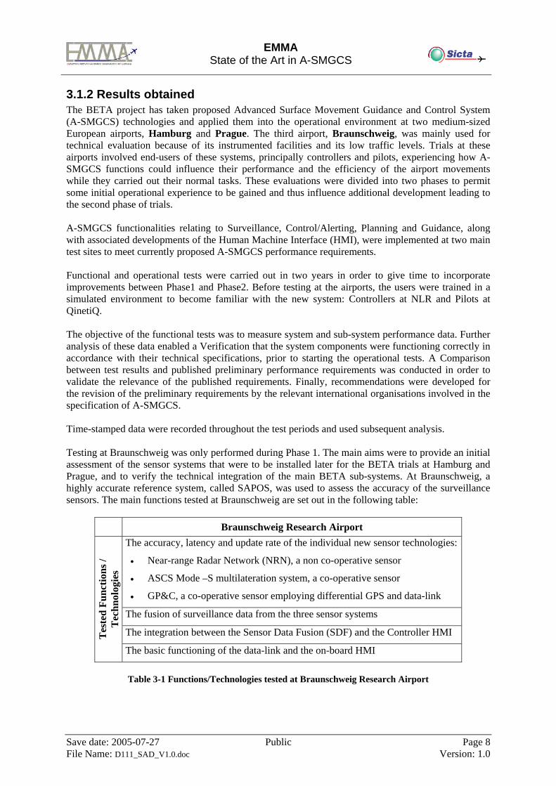
3.1.2 Results obtained The BETA project has taken proposed Advanced Surface Movement Guidance and Control System (A-SMGCS) technologies and applied them into the operational environment at two medium-sized European airports, Hamburg and Prague. The third airport, Braunschweig, was mainly used for technical evaluation because of its instrumented facilities and its low traffic levels. Trials at these airports involved end-users of these systems, principally controllers and pilots, experiencing how A-SMGCS functions could influence their performance and the efficiency of the airport movements while they carried out their normal tasks. These evaluations were divided into two phases to permit some initial operational experience to be gained and thus influence additional development leading to the second phase of trials. A-SMGCS functionalities relating to Surveillance, Control/Alerting, Planning and Guidance, along with associated developments of the Human Machine Interface (HMI), were implemented at two main test sites to meet currently proposed A-SMGCS performance requirements. Functional and operational tests were carried out in two years in order to give time to incorporate improvements between Phase1 and Phase2. Before testing at the airports, the users were trained in a simulated environment to become familiar with the new system: Controllers at NLR and Pilots at QinetiQ. The objective of the functional tests was to measure system and sub-system performance data. Further analysis of these data enabled a Verification that the system components were functioning correctly in accordance with their technical specifications, prior to starting the operational tests. A Comparison between test results and published preliminary performance requirements was conducted in order to validate the relevance of the published requirements. Finally, recommendations were developed for the revision of the preliminary requirements by the relevant international organisations involved in the specification of A-SMGCS. Time-stamped data were recorded throughout the test periods and used subsequent analysis. Testing at Braunschweig was only performed during Phase 1. The main aims were to provide an initial assessment of the sensor systems that were to be installed later for the BETA trials at Hamburg and Prague, and to verify the technical integration of the main BETA sub-systems. At Braunschweig, a highly accurate reference system, called SAPOS, was used to assess the accuracy of the surveillance sensors. The main functions tested at Braunschweig are set out in the following table:
Braunschweig Research Airport The accuracy, latency and update rate of the individual new sensor technologies:
• Near-range Radar Network (NRN), a non co-operative sensor
• ASCS Mode –S multilateration system, a co-operative sensor
• GP&C, a co-operative sensor employing differential GPS and data-link
The fusion of surveillance data from the three sensor systems
The integration between the Sensor Data Fusion (SDF) and the Controller HMI Tes
ted
Func
tions
/ T
echn
olog
ies
The basic functioning of the data-link and the on-board HMI
Table 3-1 Functions/Technologies tested at Braunschweig Research Airport
EMMA
State of the Art in A-SMGCS
Save date: 2005-07-27 Public Page 9 File Name: D111_SAD_V1.0.doc Version: 1.0
Hamburg / Prague Airports The accuracy, timeliness and integrity of the overall surveillance
The correctness and timeliness of the alerting function
The availability of correct flight plan information in the electronic flight strips
The ability of the system to provide a taxi route (Prague only)
The ability of the system to suggest a departure sequence
The ability of the system to deliver tactical clearance instructions via data-link
to test aircraft/vehicles Tes
ted
Func
tions
/ T
echn
olog
ies
The correct functioning of the Controller HMI and on-board HMI
Table 3-2 Functions/Technologies tested at Hamburg and Prague Airports
3.1.3 Lessons learnt Airlines should be encouraged to modify their Standard Operating Procedures (SOPs) for the use of Mode-S transponders on the ground. Issuing NOTAMs at individual airports is not enough to ensure that pilots adopt the correct procedures. Adequate surveillance for safety critical applications, such as maintaining good visibility capacity in low visibility conditions, may not be achievable until all aircraft and vehicles operating in the aerodrome manoeuvring area are suitably equipped and co-operating. A significant step forward towards this goal would be to find a low cost means of equipping general aviation aircraft and vehicles. The link between the A-SMGCS and the rest of the ATM needs to be clearly defined in terms of data ownership, transfer means, access rights and responsibilities. A common shared database for the whole system is desirable, but responsibilities for database content and data integrity need to be clearly defined. Improvements should be made to the controller HMI, particularly the presentation of the electronic flight strips and the interaction with them. The close co-operation of controllers and pilots has been, and will remain, essential in developing the HMI and in implementing procedural changes required to take full benefit of the new technology. Controllers have been trained to do their job in a particular way, primarily to ensure that safety is maintained at all times. This level of training may also influence their acceptance of a new system such as BETA, which has not yet reached a fully developed operational state. The use of the new tools may not always be consistent with their previous training and this could cause them to question the viability of certain functions. For future trials, controllers training should set additional focus on providing an understanding of the role of the system and the expected benefits. Benefits can be explained to the controllers but acceptance comes through use in situations where the benefits can actually be experienced. The testing in good weather and low traffic levels does not necessarily demonstrate that. The system needs to be tested under conditions when the controller is experiencing a significant workload with the current system before a proper assessment can be made of the type of advantages that could be achieved with the A-SMGCS. Since the greatest benefits of A-
EMMA
State of the Art in A-SMGCS
Save date: 2005-07-27 Public Page 10 File Name: D111_SAD_V1.0.doc Version: 1.0
SMGCS are expected in low visibility, procedures should be developed to permit operational testing of a future A-SMGCS under low visibility conditions. Revised operational procedures are required to accommodate the introduction of various components of an A-SMGCS, both for the controller and for the pilot, especially for systems such as data-link. Future R&D activities should focus on applications that improve ATM operations, as well as on developing CNS technologies. Research is needed into the way the role of the human will be affected by Air Traffic Management developments, particularly with the use of data-link and new HMI. It is advisable to run tests over longer periods (estimated to be of the order of 40 hours of operational testing) and with many more aircraft that are suitably equipped and to perform prolonged development at the airports themselves. Revised procedures, longer periods of observation, test periods in reduced visibility conditions, and many participating aircraft are needed to obtain the level of quantitative results to show a significant benefit. The active participation of pilots, controllers and regulatory bodies will be necessary. To make a quantitative benefit assessment it will be necessary to find meaningful objective measures and to define and establish a stable baseline from which to measure. This may only be possible in a simulation environment. Further simulation trials should aim to provide a more quantifiable result of the potential operational benefits under high traffic load conditions. Ground simulation trials could also address some aspects of the expected benefits from operating A-SMGCS under low visibility and high traffic conditions. A cost benefit analysis should be carried out. To enable a realistic cost benefit analysis, participation of all significant stakeholders will be required. The distribution of benefit and cost is likely to be uneven so it is important for all participants to understand the implications for implementation of A -SMGCS. Typical examples of cost benefits that should be analysed are those associated with diversions, cancellations, gate management, and taxi time. To demonstrate a benefit, it will be necessary to show that a shortfall currently exists that could be improved upon by adoption of A -SMGCS.
3.1.4 A-SMGCS Operational concept applied The BETA project's A-SMGCS concept was composed of the following four basic functions:
Surveillance,
Alerting,
Guidance and
Planning. These four functions along with the required data communications and Human/Machine Interface (HMI) supported the operational requirements proposed by ICAO for Surveillance, Control, Guidance and Routing. The operational requirements that the Surveillance Function should fulfilled are:
• to provide accurate, timely, position information on all movements within the specified coverage volume for the site;
• to provide information on the identity of authorised movements;
EMMA
State of the Art in A-SMGCS
Save date: 2005-07-27 Public Page 11 File Name: D111_SAD_V1.0.doc Version: 1.0
• to provide classification according to size or type (e.g. large, medium, small, aircraft, vehicle, obstacle/unknown) for unidentified or unidentifiable objects detected on the movement area;
• to cope with moving and static aircraft, vehicles and obstacles;
• to provide all data at an update rate sufficient to meet alerting, guidance and planning requirements both in terms of time and position;
• to provide surveillance throughout the aerodrome movement area;
• to provide surveillance throughout that part of the surrounding airspace where aircraft movements influence surface operations;
• to provide a seamless transition between the surveillance of the aerodrome surface and the surveillance of traffic in the airspace surrounding the aerodrome.
The Alerting Function evaluated all target reports continuously against a set of monitoring rules. The set of monitoring rules was configured for the specific aerodrome layout and was adaptable to different operating conditions. For the BETA A-SMGCS the following monitoring rules were implemented:
1. incursion into an active runway,
2. incursion into a restricted area,
3. crossing of a lit stop-bar and
4. deviation from assigned route (Prague only). Although not currently specified as a requirement for A-SMGCS, the BETA system in Prague was also configured to monitor flight plans and the operation of flight strips. The alerting function requirements postulate that the system should detect alert situations, such as:
Potential collisions;
Incursions into the runway strips and any other designated protected areas; and
Deviations from assigned routes. Having detected an alert situation, the Alerting Function provided alert reports to specified users. Each alert report contained adequate information about the alert situation. The Guidance Function provided the means to support pilots to taxi in accordance to their plans. Various guidance means were available in parallel: ground based guidance means (signs, lights, stop bars etc.), follow-me cars, instructions by voice, and data link transmission of complete plans and clearances to aircraft equipped with onboard HMI and data link capability. For the Guidance Function, the operational requirements were:
• to provide the processing and signalling means in order to transfer to the pilot and/or vehicle driver the advice and information associated with a clearance;
• to provide clear indication to pilots and vehicle drivers to follow an assigned route; • to enable all pilots and vehicle drivers to maintain situational awareness of their position on
the assigned route; • to be capable of accepting a change of route at any time;
EMMA
State of the Art in A-SMGCS
Save date: 2005-07-27 Public Page 12 File Name: D111_SAD_V1.0.doc Version: 1.0
• to be capable of indicating routes and areas either restricted or not available for use;
• to allow monitoring of the operational status of guidance devices; and
• to provide conflict resolution by activating stop bars. The Planning Function generated plans for ground movements. A complete plan for any movement of a single object comprised the two elements of route- (as outlined in the ICAO manual) and time information (e.g. start-up time) in order to gain the expected efficiency benefit. The operational requirements for the Planning function, which relates mostly to the taxi routing and departure/arrival sequencing aspects, were the following:
1. Enable a route to be designated for each aircraft and vehicle on the movement area;
2. Allow for a change of destination at any time;
3. Allow for a change of a route to the same destination at any time;
4. Not constrain the pilot’s choice of runway exit following the landing;
5. Minimise taxi distances in accordance with the most efficient operational configuration;
6. Recommend runway assignments for departing aircraft;
7. Generate recommended taxi clearances/instructions for arrival and departure aircraft based on the taxi plan (accepted by the relevant controller) for the specified aircraft;
8. Provide sequencing of aircraft to ensure minimum delay and maximum utilisation of the available capacity of the aerodrome;
9. Provide optimised start-up and push-back sequences/times;
10. Be rapidly responsive to operational changes, 11. Be interactive with the Alerting function to minimise junction conflicts.
3.1.5 Useful considerations for EMMA Concept
3.1.5.1 Managerial Issues From the BETA experience is recommended to avoid high level goals and to be more specific in terms of the objectives in future projects. For future projects the BETA method of specifying OC (and test plan) first and system design later is recommended strongly, with some improvement on timely production of critical documents (like the OC) and in depth analysis of existing A-SMGCS performance, before starting to test higher level A-SMGCS functions and procedures.
3.1.5.2 Technical Issues The BETA project included man-in-the-loop simulator sessions for prototype evaluation and controller training. They confirmed that field-testing requires complementary simulator exercises, favouring user involvement, and that the testing and training can be extended with higher traffic density and more safety-related scenarios than possible at real airports. Rapid prototyping with at least two test phases and pre-evaluation was an excellent approach. A minor point was that in the first cycle the level of system functionality was not as complete as had been planned. As a consequence the cycle one
EMMA
State of the Art in A-SMGCS
Save date: 2005-07-27 Public Page 13 File Name: D111_SAD_V1.0.doc Version: 1.0
training content had to be reduced in favour of more prototype testing with controllers in the loop. System readiness in cycle two training was better, allowing measured exercises on controller performance and Departure Planning.
3.1.5.3 Implementation Issues An outcome from the BETA work is that a primary aspect that needs to be resolved in any implementation of an A-SMGCS is the acceptability of the HMI by the end-users of the system. Since a principal intention of the A-SMGCS is aimed at providing the operator with the necessary tools to support him/her in the performance his/her tasks more effectively in all conditions, then any new HMI should be evaluated by the end-users throughout the development cycle prior to operational implementation. The BETA trials revealed that sufficient testing of an operational implementation of an A-SMGCS requires a more extended period than was available within the time-scales and resources of the BETA project. In order to confirm that the functional performance requirements are met by an installed A-SMGCS, there would be a necessity to obtain weeks (of the order of about 400 hours) of data collection before there is sufficient quantity from which statistical probabilities of the order of 99.9% can be derived. Additionally, any A-SMGCS implementation will need to initially ensure that basic surveillance information (i.e. detection and identification) is available for all movements throughout the aircraft manoeuvring areas prior to further A-SMGCS functions being incorporated. Reductions in the availability or accuracy of the surveillance information are likely to impose limitations on the performance and usability of the other components of the system. An assessment would then be required to determine whether the level of surveillance is adequate for the type of A-SMGCS being implemented or whether the extension or addition of another sensor system is necessary. Implementation towards a fully operational system would need to be a staged process, initially providing the operator with access to improved information, supplementing that which is currently available, in order to support the operator in the execution of their tasks. For instance, the integration with existing systems at the airport, such as surveillance sensors and flight plan database systems has to be fully verified before functional assessment of the A-SMGCS components can be started. Development and implementation of A-SMGCS functions at an airport needs to be supported by representative simulation facilities to improve the transition to the new systems. Experiences from the BETA trials showed how user acceptability is dependent on confidence in the operational performance of the system. Although the meeting of the A-SMGCS functional requirements should establish the capability of the system, it might be proposed that a user assessment is required in stages of increasing traffic density and reduced visibility conditions to demonstrate its performance at the operational level. Therefore, a simulation environment needs to be available in order to provide a realistic representation of the airport and its associated traffic movements. This should provide the necessary training situations that would allow the user to become familiar with the operation of the system under all conditions and to be able to use the system to respond to any situation that is likely to be encountered at the airport. Operator appraisals of the A-SMGCS at the airport can also be performed prior to an actual operational use of the system. This is consistent with the mandatory training and licensing of airport controllers via the use of simulation tools. Similarly, certain A-SMGCS components, such as an enhanced surveillance display and the application of electronic flight strips, can be seen as developments of current systems that are in use. Although aspects of the use of these components may be new to the controllers, the operational implementation of this function should be capable of being performed without significant changes to working practices or procedures. Where tools are being introduced that provide much newer functions to the user, associated for instance with the planning/routing and guidance processes, an evaluation
EMMA
State of the Art in A-SMGCS
Save date: 2005-07-27 Public Page 14 File Name: D111_SAD_V1.0.doc Version: 1.0
period may be required prior to full operational use. This would allow the tools to be used initially in an advisory role to assess their performance and establish user acceptability in the operational environment before the information supplied by these tools is used directly for control decisions. The BETA trials highlighted that each airport can have its own characteristics and, to a certain extent, methods of operation. Where possible, these should be assessed and incorporated into the simulation environment in order to configure the A-SMGCS to the airport before it is fully installed. However, some refinement of the A-SMGCS functions may be required following the initial implementation and operational testing at the airport. Ideally, the A-SMGCS implementation should be capable of being adapted to local procedures rather than forcing changes in procedures because of the inflexibility of the functions. This would make the system more readily acceptable to the users and require less training and would also mean that the system was more adaptable to different airports. Furthermore, the trials showed that automating a new system is very time consuming and not achievable within just a limited number of days. So, it is highly recommended to improve the training and extend the education of the operators (e.g. pilots and controllers) in order to avoid problems in using a new system. Implementation of an operational A-SMGCS is also closely associated with developments in other areas of Air Traffic Management, most notably where the A -SMGCS functions are dependent on the equipment status of the aircraft. This includes aspects such as the use of data link for clearances and the application of Automatic Dependent Surveillance - Broadcast (ADS-B). The availability of these types of system is reliant on specification of the technology that is to be used and on the regulations and procedures being issued by the governing bodies. In these circumstances, co -ordination is essential and it is likely that it will be specified in terms of a number of years before aircraft are required to be suitably equipped. A-SMGCS implementation will therefore need to be flexible to allow for future system developments to be introduced progressively as regulations and operational specifications become defined. So, one of the major conclusions of the above discussion is to better integrate on -board capabilities/performances into the A-SMGCS operational requirements. This should be considered in the further ICAO manual for this work. All the public documentations produced inside the BETA project are available on the BETA web site [17]
EMMA
State of the Art in A-SMGCS
Save date: 2005-07-27 Public Page 15 File Name: D111_SAD_V1.0.doc Version: 1.0
3.2 ATOPS ‘A-SMGCS Testing of Operational Procedures by Simulation’ and SAMS
3.2.1 Background and Objectives of ATOPS project ATOPS (A-SMGCS Testing of Operational Procedures by Simulation) was one of the contracts awarded by the European Commission - DG VII in the 4th R&D Framework Programme. The project duration was 18 months, starting at January 1999. Currently, operational procedures on the surface of an aerodrome depend on pilots, air traffic controllers, and vehicle drivers using visual observation of the location of the aircraft and vehicles in order to estimate their respective relative positions and avoid the risk of collision. Pilots and vehicle drivers rely on visual aids (lighting, signage, and markings) to guide them along their assigned routes and to identify intersections and holding points. Pilots and drivers are subject to clearance-to-proceed instructions issued by the controller based on these visual references. During periods of low visibility, controllers must rely on the pilot’s RTF reports and surface movement radar to monitor separation and to identify conflicts. In these conditions, pilots, and vehicle drivers find that their ability to operate in the “see and be seen” mode is severely impaired. The European Commission Transport Directorate has been actively encouraging A-SMGCS developments through a number of projects, and new procedures using A-SMGCS technologies were being developed. Currently the human operators are helped in their tasks by some technological tools but these have rather limited capabilities. For instance, in the surveillance function, a surface movement radar (SMR) partially, replaces the eyes of a controller: the SMR gives the position of the objects on the airport platform but not their identity. The controller has to mentally correlate the reported positions with identities gathered by other procedures and constantly keep in mind these associations. Similarly in the control function, the controller has to visually monitor the position of objects and evaluate all this data to ensure that aircraft and vehicles are properly separated and do not enter restricted or prohibited zones. In the field of routeing/planning, the controller must know which runway will be used for each flight, when it will be used, and which taxiways are available for use at any given time in order to route an aircraft on the manoeuvring area. In the guidance function, the controller (or an assistant) has to manually select the guidance means (lights, signs, stop bars…) to guide the aircraft along the designated taxi route. The ATOPS main objectives were: -to identify, with the help of end-users and service providers, operational procedures using A-SMGCS that are expected to enhance the efficiency and capacity of airport ground movements in a safe manner; -to conduct simulation tests using the SAMS (SMGCS Airport Movement Simulator) platform to enable pilots and controllers to evaluate the chosen procedures and record performance data. The ATOPS project has been set up to reach several objectives. These are:
EMMA
State of the Art in A-SMGCS
Save date: 2005-07-27 Public Page 16 File Name: D111_SAD_V1.0.doc Version: 1.0
1. to define and test operational procedures involving A-SMGCS, to demonstrate some of the real benefits of A-SMGCS
2. to evaluate performance parameters for associated sub-systems
3. to demonstrate the validity and effectiveness of real time operator-in-the-loop simulation means for supporting ATC procedures definition and evaluation
4. to provide a baseline for 5th Frame Work Programme (FWP)
5. to consult/ inform all interested parties on the conduct and results of the project and to take account of their comments in the final reporting.
In addition to the project objectives listed above, the results of the ATOPS simulations were expected to provide: -An operational emphasis to complement the technological emphasis of previous A-SMGCS research, e.g. DEFAMM. -Initial evidence for business cases for implementing A-SMGCS. -An input into the ICAO Manual of A-SMGCS for which PT/2 of the AOPG of the ICAO EANPG was responsible. The project duration was 18 months, for collating procedures, conducting simulation tests of Heathrow and Schiphol airports and analysing results. A three-month extension period was used for completing the final reports and dissemination activities.
3.2.2 Results obtained The first objective, related to the definition of operational procedures was met by:
• defining a list of ATC procedures based on the use of an A-SMGCS • testing a limited number of these procedures in a simulated busy airport environment • identifying benefits arising from the use of such procedures • consultation of ATC authorities.
Through the use of comprehensive questionnaires and interviews with Air Traffic Control authorities in four main European airports (Heathrow, Charles De Gaulle, Schiphol, Frankfurt), the ATOPS project identified the airports' present SMGCS, future planned A-SMGCS, perceived business benefits of A-SMGCS and possible operational procedure topics for A-SMGCS (distinguishing basic or core procedures from advanced procedures). This provides a detailed overview of current practice and future trends as far as ground movements are concerned. A number of selected procedures have been tested at Heathrow and Schiphol using the SAMS real-time, man-in-the-loop simulation platform, linking together a cockpit simulator, control tower simulator and a core A-SMGCS simulator. Because the SAMS platform encountered technical difficulties and could not be completed, only core procedures have been addressed during the ATOPS simulation. General feedback from the ATCOs who participated in the simulations indicated that A-SMGCS is extremely helpful in supporting the ATCOs in the tasks of identifying and guiding traffic on the airport surface. Although no quantitative data have been collected, A-SMGCS appears to improve the amount of traffic that can be moved in low-visibility conditions. The observed reduction in radio/telephony communications has indicated that ATCO workload decreases. The second objective, related to performance parameters, was met by carrying out tests of some new A-SMGCS based operational procedures in such a way that data was derived and used in the process of defining sub-systems and equipment performance parameters.
EMMA
State of the Art in A-SMGCS
Save date: 2005-07-27 Public Page 17 File Name: D111_SAD_V1.0.doc Version: 1.0
The third objective, related to the validation of simulation means, was reached by demonstrating through test scenarios similarities between the simulated and real world operations. The fourth objective, providing a baseline for the 5th FWP, was met by the preparation of a report outlining testing that was usefully performed in the context of the 5th FWP. The last objective, consulting and/or informing all interested parties, was met by setting up internal consultations and two forums. Forum 1 is a consultation forum and will be set up prior to the start of the simulation to consult end users and Forum 2 is a dissemination forum to inform end-users, equipment providers and regulatory authorities on the results of the simulation.
3.2.3 Lessons learnt The ATOPS identified controller procedures were as follows.
3.2.3.1 Identification and Identification Verification For these tasks and the related interactions with the system, specific ergonomic investigations are needed for future systems. Examples for such subjects of investigations are:
• In which format shall the identification states be presented to the controller (colour, label, electronic flight strip etc.), which identification states are of relevance for the controller
• How can the recording of the identification verification process be simplified by the system (clicking on a field in the label or in the electronic flight progress record etc?)
• What kind of system integrity and accuracy is minimally required for the ATCO to be able to use an A-SMGCS for identification and identification verification purposes (positional accuracy, label swap, label drop, etc.)
• Further work is required on simulation of multi-sensors. In particular the ability to introduce realistic delays for various sensor performances should be addressed. Eventually the reliability of sensors should also be simulated to present realistic situations to the users of the simulator.
3.2.3.2 Conflict Detection and Alert The airports consulted and the Controllers involved in the simulations were convinced that Conflict Detection/ Alert systems were required. Areas that need to be addressed for such systems include:
• Designing alert systems for particular areas of airports (e.g. so the ATCO would only see alerts relevant to the area under his/her control)
• Presentation of alerts on displays and associated warnings (including which displays and format) • Procedures for alerting controllers irrespective of whether they are working head up or head
down.
3.2.3.3 Conditional Movement Plans and Conditional Clearances Possible items for future investigations with respect to the use of conditional movement plans and conditional clearances identified during the ATOPS project are:
• How to provide the controller with system generated movement plans to support him/her in the movement and route planning activity (e.g. questions of optimal mnemonic presentation of plans etc.)
• How to give the controller the opportunity to modify and accept plans in order to select the optimal plan.
• How to present conditional movement plans and conditional instructions in most concise form to the controller (e.g. 'cross after ...', 'give way to ...')
• How to present issued clearances and instructions (including conditional ones) for the moving mobiles (label information, presentation of electronic flight and movement progress records etc.) in a way that the controller can easily memorise the issued clearance
EMMA
State of the Art in A-SMGCS
Save date: 2005-07-27 Public Page 18 File Name: D111_SAD_V1.0.doc Version: 1.0
• How to ease the recording of the controller decisions and the issued clearances by the system (clicking on waypoints and selecting time slots on the movement screen or in the electronic flight progress record etc.)
3.2.3.4 Advanced A-SMGCS Procedures The ‘advanced’ procedures still require a lot of investigation in the near future:
• A number of advanced procedures were listed that could have been simulated in ATOPS but were not because of the lack of particularly capability of the SAMS platform. These procedures can be further developed in future work.
• The interaction of the ATCO with these advanced A-SMGCS tools is an area that requires research. Tools such as automatic routeing and planning have an important impact on the way the ATCOs perform their task.
• Another area of research would be the involvement of other users besides the ATCOs. Pilots for instance will also have to be involved if one starts to develop automatic routeing tools.
• Ways of presenting information related to automatic routeing to pilots need to be investigated further.
• If on-board tools are going to be used, one will need to keep in mind that most likely not all aircraft will be equipped with this kind of instrumentation. How will an A-SMGCS cope with a mix of equipped and non equipped aircraft?
3.2.3.5 A-SMGCS Sub-System Performance The performance of A-SMGCS sub-systems is something that needs to be investigated. Once it is known what acceptable performance figures for A-SMGCS sub-systems are, A-SMGCS manuals can be completed with performance requirements of which many are still unknown. A simulation platform would be ideal for this kind of investigation.
3.2.3.6 Simulation Platform The project faced the egg and the hen problem. Developers expected to be provided with procedures to develop the HMI according the user needs, whilst controllers expected to see a tool in order to specify how to use it.
• For any further testing of new procedures for A-SMGCS, the simulation platform should be well understood in terms of its capabilities and the ‘end-users’ and authors of procedures should be well familiarised with it.
• Further testing of A-SMGCS and associated new procedures are carried out in simulation as it allows new concepts to be well tested under all conditions before expensive airport installations.
• Future A-SMGCS platform development, whether based on SAMS or otherwise, should take account of the technical and management findings.
3.2.3.7 A-SMGCS Operational concept applied The technologies employed by ATOPS project were the same as those used in the SAMS platform. This subsection summarises the A-SMGCS concept as obtained from the airports consulted in ATOPS and outlines A-SMGCS procedures as suggested by ATCOs involved in the project.
3.2.4 Useful considerations for EMMA Concept An A-SMGCS may have other benefits such as more efficient stand utilisation, taxiway utilisation, reduction in controller and/or pilot workload, reduction in required skill levels, reduction of aircraft engine emissions due to less ground holding, and a reduction in the costs associated with co-ordination. Undoubtedly an A- SMGCS will help to prevent GMC capacity becoming a constraint to increases - beyond present theoretical maxima - in Low Visibility weather conditions. It could also be argued that an A-SMGCS may have the ability to increase runway capacities, at airports that do not separate to absolute minima more cost effectively than increasing the skills of the operational staff and
EMMA
State of the Art in A-SMGCS
Save date: 2005-07-27 Public Page 19 File Name: D111_SAD_V1.0.doc Version: 1.0
modifying the procedures used. The perceived benefits of A-SMGCS as mentioned by the consulted airports are listed below. Runway Capacity Benefits:
• The airports do not expect there to be any increases in runway capacity as a result of implementing A-SMGCS in day or night conditions.
• Schiphol expects low visibility runway capacity figures to be brought up to normal day levels if A-SMGCS is implemented.
• Heathrow does not expect an increase in runway capacity as a result of implementing A -SMGCS. However a basic labelled SMR would permit GMC to match capacity enhancements produced by the use of MLS.
GMC Capacity Benefits:
• Schiphol expects better punctuality, reduced controller workload, and more efficient use of stand capacity. It also expects reduced delays in low visibility conditions.
• Heathrow does not expect capacity to increase in day operations. Capacity might increase at night with the help of a labelled SMR.
• Heathrow stated that a basic labelled SMR would permit GMC to match capacity enhancements produced by the use of MLS in LVPs.
• CDG expects that taxi times would be optimised in all conditions. Efficiency Benefits:
• Schiphol considers that A-SMGCS would allow less position reporting between controllers and pilots. This would decrease controller workload.
• Schiphol and CDG think that taxi times would be optimised in day and night operations. CDG think it would be optimised in low visibility also.
• Heathrow thinks it possible that there would be a reduction in queue size at the holding point during day and night operations. Emissions could reduce as a consequence. There could also be better data exchange, which would improve stand planning.
• Heathrow thinks that A-SMGCS would allow a greater number of towing movements at night and in low visibility conditions.
Safety Benefits: All airports agree that a Conflict Alert function would maintain or increase safety levels in all conditions. However, the following points were noted:
• Heathrow hoped that the use of Conflict Alert would not provide too many “nuisance” alerts in high density operations.
• Schiphol hoped that computer automation would not decrease the controllers’ situational awareness.
• CDG commented that an efficient planning and routing function would reduce the number of conflicts actually occurring and provide a true conflict alert rather than conflict detection.
• All airports expect there to be safety improvements on taxiways during low visibility conditions as a result of A-SMGCS implementation.
Any Other Benefits:
• Heathrow considers that there would be benefits in sharing information with the airport authority, for example, recording amount of tonnage across blocks to help plan pavement repairs.
EMMA
State of the Art in A-SMGCS
Save date: 2005-07-27 Public Page 20 File Name: D111_SAD_V1.0.doc Version: 1.0
• CDG considers that there would be a monetary saving if A -SMGCS implementation relaxes regulations about the airfield lighting system at night and during low visibility operations. Otherwise it would be costly for ADP to implement red/green lighting.
Other useful information that could be useful in the BETA project:
• Description of Typical Controller Tasks (in ATOPS Deliverable Report ‘D3’) • ATC Procedure Design and Hazard Analysis (in ATOPS Deliverable Report ‘D3’)
The Final Summary Report of the ATOPS Project is available on the EC web site [15].
3.3 DEFAMM ‘DEmonstration Facilities for Airport Movement Management’
3.3.1 Background and Objectives of DEFAMM project DEFAMM (Demonstration Facilities for Airport Movement Management) is one of the contracts awarded by the European Commission - DG VII in the 4th R&D Framework Programme. The project duration was 36 months, starting at December 1995. The aim of the DEFAMM project (Demonstration Facilities for Airport Movement Management) was to demonstrate the major A-SMGCS (Advanced Surface Movement Guidance and Control System) functions with real facilities in a near-operational airport environment. The project has been carried out by partners from industry, research institutes, airport and ATC authorities in the time frame from December 1995 until March 1999. In DEFAMM several A-SMGCS demonstrators were built up by adaptation development including prototype subsystems. These demonstrators have been tested in operational environments of four European airports including the first large-scale demonstrator covering all A-SMGCS basic functions that are Surveillance, Control, Routing/Planning and Guidance. The main objectives of the DEFAMM Project were:
• To implement a demonstrator system for advanced surface movement guidance and control functions.
• To show the users (ATC providers, airports, airlines) the functions through which they would gain the benefits of increased traffic management efficiency at maintained or improved safety levels.
• To get the feedback from controllers, pilots and drivers on the acceptability of the demonstrated means.
Other important but more technical issues of the DEFAMM project were:
• To build a system architecture, which is modular and open in order to introduce new technologies and to cope with specific airport conditions without discarding all existing equipment. This was an important issue for DEFAMM itself but the results can also be a guideline for possible follow-on projects.
• To cover a sufficient variety of airport configurations and to use already existing facilities for the demonstration of different A-SMGCS functions.
• To enhance the integration of existing systems on the airport by showing the advantages gained by data exchange during the DEFAMM demonstrations.
• To define the DEFAMM demonstrations with the customer and users together. It is important to identify in a common process those project parameters which form the qualitative and quantitative objectives of the demonstrations and which are of relevance to safety levels and to efficiency benefits.
To achieve these objectives it was planned that the DEFAMM demonstration facilities as completely
EMMA
State of the Art in A-SMGCS
Save date: 2005-07-27 Public Page 21 File Name: D111_SAD_V1.0.doc Version: 1.0
as possible cover the required A-SMGCS functions in the form of initial implementations. These realisations and related validations were planned for the time frame between 1996 and 1998. The support of A-SMGCS functions with technical means and the related testing with the users always leads to new conclusions to be used in optimising cycles. It was expected that the results of the DEFAMM project will build a basis for follow-on projects. The DEFAMM results shall be used to settle the surveillance and control functions and support further research and development on planning and guidance methods. An important use of the DEFAMM demonstration results will be the development of new or adapted operational procedures and defined responsibilities in the management of the airport traffic. This aspect is important in order to fully achieve the offered benefits of the technical systems.
3.3.2 Results obtained
Four airports participated in the demonstration of the A-SMGCS. This is, because the total range of the DEFAMM functions forms a rather complex system and one test side only would have been completely overloaded. Furthermore, it should be demonstrated that an A-SMGCS can be profitably embedded in different environments with a variety of airport facilities and topological constraints. A further advantage was the possibility to use several independent test environments like reference systems for positioning or digitised airport maps. Last but not least, the support from the airport authorities was shared while the test results were enriched by the engagement of several users of the A-SMGCS. Especially their experiences were accumulated for the success of this project.
The airports for the DEFAMM demonstrations were:
• Bergamo • Braunschweig • Paris/Orly • Köln/Bonn
In Bergamo a new type of a 95 GHz mini radar was tested. In Braunschweig a new combination of cooperative and non-cooperative sensors was tested, including the new Near Range Radar Network NRN and DGPS. In Orly a new A-SMGCS planning function for movement expedition of aircraft in complex crossing situations was demonstrated in combination with switchable signs, utilising a specific controller working position for operation. In Köln/Bonn functional and operational tests were performed with the first large-scale A-SMGCS demonstrator, providing the functions Surveillance, Control, Planning/Routeing and Guidance in real-time under near operational conditions.
To summarise the results of the DEFAMM project with respect to the project goals, it can be stated that:
• Demonstrator systems for advanced surface movement guidance and control functions have been implemented at four European airports including the first large-scale A-SMGCS demonstrator in Köln/Bonn.
• Feedback from controllers, pilots and drivers on the acceptability of the demonstrated means was gathered and gave valuable insight for future development and research projects.
• The functions that provide benefits in efficiency and safety were shown to users (ATC providers, airports, and airlines).
• A modular and open system architecture was built which can be used as a guideline for possible follow-on projects.
• A variety of airport configurations and already existing facilities were used for the demonstration of different A-SMGCS functions.
• The advantages gained by data exchange at the demonstrations of DEFAMM gave motivation
EMMA
State of the Art in A-SMGCS
Save date: 2005-07-27 Public Page 22 File Name: D111_SAD_V1.0.doc Version: 1.0
to enhance the integration of existing systems at the airports.
3.3.3 Lessons learnt The DEFAMM Surveillance Subsystem was realised as a Multi-Sensor System with Sensor Data Fusion (SDF), resulting in a labelled display of the traffic situation for the controller. It was highly accepted. For the individual components it is pointed out in the DEFAMM Evaluation Report how they have to be improved in order to fulfil operational demands. Improvements are needed in terms of continuity of detection by the individual sensors, in terms of enhancements for clear distinction between different objects by the non co-operative sensors and in terms of unambiguous combination of the information by the Sensor Data Fusion. Additionally, the presentation of the labels and the definition of the content of the information presented in the label may profit from harmonisation with controllers’ needs. The Control Function with its Conflict Detection Support was well accepted by the controllers. This was especially true for the area conflict detection (intrusion into prohibited areas) and the runway incursion detection. However, specific multiple line-ups and situations where several aircraft interact on one runway (enhanced procedures) should be studied by future systems. Concerning the movement conflicts on taxiways, it turns out that it is difficult to find clear criteria for the conflict indication. Investigations are recommended into how it is possible to reduce the reaction time to be considered by the system in order to reduce the necessary safety distances. This could be done possibly by automatic guidance commands for pilots and drivers. Controllers should be taken out of this loop because they cause the largest delay in the system. The Guidance Function of DEFAMM, realised by ground based means (switchable centre-line lights) and on-board means (the Pilot Driver Assistance Display) was well accepted and highly appreciated by pilots and drivers. It was envisaged by these end users that Guidance in a future system shall be a combination of ground based and on-board means and that the guidance means shall not fully replace the voice interaction between controllers and pilots. Spoken interaction, as a basic human communication form should still be used to establish the basic contact between the controllers and the pilots and drivers. Ground-based guidance may profit from ergonomic investigations on the size of the centre-line light segments in use and on the timing conditions for their activation. The Planning Functions and the related interactions were not accepted by the controllers, because its handling does not conform to their current working habits. Moreover, the required inputs to the system were felt to be time consuming. Therefore, the planning features need investigation with respect to the new role of controller in the planning and negotiation process. The interactions with the system possibly combined with hand-over procedures between control units should be reviewed. The non-acceptance of the planning interactions by controllers leads to a dilemma, because planning support by the system is a prerequisite to several A -SMGCS functions. Guidance support and several Control Functions are only possible if routes and movement plans are known to the system. The planning gap in the gate-to-gate management can only be closed if the A-SMGCS performs movement-planning functions. As long as the interaction with the system for the planning function is not accepted by the controllers, these planning functions cannot be provided by the A-SMGCS.
3.3.4 A-SMGCS Operational concept applied
In DEFAMM a generic functional A-SMGCS architecture of main functions was developed, comprising the A-SMGCS basic functions and required supporting functions. This general outline of the top-level functional decomposition was designed step by step and was reviewed with respect to suitability and applicability throughout the project.
The goal of the development of the functional architecture was to find a structure that
EMMA
State of the Art in A-SMGCS
Save date: 2005-07-27 Public Page 23 File Name: D111_SAD_V1.0.doc Version: 1.0
• is clear, concise and evident • matches the four basic functions as described by the ICAO A-SMGCS Manual • allows scalability and adaptability to specific airport's needs • allows the assignment of modular subsystems to the functions • shows the main communication relations in the system
The functional architecture leads to decomposition into the following main functions:
• Surveillance
o Non-cooperative sensors to detect all objects, o Cooperative sensors to clearly identify controlled vehicles and aircraft o Interfacing to external sources o ASDE o E-Scan ASDE o Mode S multilateration o DGPS o ASR
• Guidance
o Manual or automated switching of centreline light segments and stop-bars o Data link/On-Board display system for clearance negotiation and automated
transmission of taxi plan and guidance commands o On-board display shows the mobile’s own position on the assigned route, and the
negotiation on taxi plans (request clearance, receive clearance, accept clearance), and the cleared movement plan (taxi route and time slots)
• Routing/Planning
o The task of the controller will be to assess the plans provided by the system. o The controller can initiate the generation of taxi-plans, edit and accept plans proposed
by the system and validate the plans by presentation on the screen of the Controller Working Position
• Control
o Associated with the Control function is the subsystem Conflict Handling which takes
the whole traffic information from the Sensor Data Fusion and provides the complete and assessed traffic information to the Controller Working Position. This includes the information about all controlled (identified) mobiles and all non-controlled (non-identified) objects, the information about traffic and plan deviation conflicts.
• the Human Machine Interface Function • the two support functions Management and Communication
EMMA
State of the Art in A-SMGCS
Save date: 2005-07-27 Public Page 24 File Name: D111_SAD_V1.0.doc Version: 1.0
Based of this functional structure the definition of subsystems and their assignment to each of the top-level functions was done.
3.3.5 Useful considerations for EMMA Concept A stringent engineering approach proved to be an essential precondition for the successful execution of such an ambitious project and the related demonstrations for reliable evaluations. Much care should be taken in future projects to select a 'best practice' methodology and to ensure the consequent progress of the work according to the chosen method.
The Requirements Analysis and the related Use Case and Event Trace descriptions were a fundamental basis for the design as well as for the testing processes. The procedures and interactions developed during the analysis and design process of DEFAMM can form a good basis for further investigations and research activities in future programs whereby the interactions for the planning needs review and extra careful investigation.
Simulation of new procedures is highly recommended for future projects to test proposed procedures under definite conditions. However, only tests with a physical realization of the system in an operational environment, as done in DEFAMM, can prove and verify the suitability of the selected solutions and the operational benefits.
The DEFAMM system design and the modularity of the system have proven to be an optimal approach for the realization of a large-scale A-SMGCS implementation. The exemplary modular decomposition should be taken into account in future projects.
The subsystems used in DEFAMM need careful improvement in order to develop from demonstration and prototype to operational systems.
A specific issue for future gate-to-gate co-ordination of air traffic is additional investigation with respect to the planning functions. They have to solve the problem to find planning features and related interactions, which are accepted by controllers in their new role in the control process.
The Final Summary Report of the DEFAMM Project is available on the EC web site.
3.4 LEONARDO ‘Linking Existing ON ground, ARrival and Departure Operations’
3.4.1 Background and Objectives of LEONARDO project LEONARDO (Linking Existing ON ground, ARrival and Departure Operations’) is one of the contracts awarded by the European Commission - DG VII in the 5th R&D Framework Programme. The project duration was 24 months, starting at December 2001. An analysis of the current situation of airports and their surroundings shows that a series of circumstances affect the efficiency of airport operation management. The main problem that LEONARDO intended to solve is this lack of coordination and efficiency in the context of Airport Arrival, Departure and Ground movement and operations, which leads to unacceptable amounts of delays and operating costs. It is foreseen that the airport and its surroundings will become the main limiting factor of the whole ATM system. These circumstances, on which the LEONARDO Project focused, are the following:
1. The lack of integration of the existing tools in operation that assist in the management of arrivals, departures and ground operations at the airport. All these tools used for the management of airport operations currently work independently. Each tool uses its own
EMMA
State of the Art in A-SMGCS
Save date: 2005-07-27 Public Page 25 File Name: D111_SAD_V1.0.doc Version: 1.0
criteria to optimise the operations it manages disregarding the information and criteria used by the others. In this circumstances only individual operations (i.e. arrivals, departures, stand operations, taxiing) are optimised, which does not mean the overall efficiency of the airport.
2. The different actors involved in airport processes (e.g., air traffic controllers, airlines, airport
operations centres and handling companies) do not always have all of the information they need when they need it and with a suitable level of reliability. An increased exchange of information between these actors could improve the management and planning of available resources.
In this context, the main objective of the LEONARDO Project was “to define a method for and demonstrate the feasibility of integrating existing tools for arrival and departure-planning management, with those derived from the planning and routing function of the ground movement”. Thus, the project proposes the integration of the existing and new airport management tools and the implementation of the Collaborative Decision Making (CDM) at the airport as the addressed solutions to be tested. Indeed, the integration of the different airport planning tools is part of the CDM concept. The level of the system integration will be the level of CDM addressed. For the integration, the first step is to accommodate arrivals and departures in the tactical operations. Further steps should aim at adapting the departures to the already existing airborne traffic, extending the time horizon to the pre-tactical phase of the planning process. The integration of arrival and departure management involving surface and gate management in both the pre-tactical and tactical planning phases is considered to optimise the use of the available resources and to provide the means to assure a stable throughput at the airport. With these proposed solutions an increase in Efficiency is expected. Safety and Capacity levels are also expected to be maintained or increased. These three are the validation objectives defined within LEONARDO. In order to achieve these objectives, a full-scale integration of existing ground, arrival and departure planning and management tools was proposed to be performed at two European airports under real operating conditions to validate such a system. Shadow mode trials were conducted at Madrid/Barajas Airport and Paris/Charles de Gaulle Airport. The study was complemented by a Collaborative Decision-Making Multi-Agent benchmark in a simulated environment, performing real time simulations. The two first levels of integration, as defined in the CDM context, are covered by the local implementations (Barajas and Charles De Gaulle), whilst the first two and third level is fully addressed by the CDMMA approach. Additional objectives that have been considered in the Project are:
• To explore and find both the strengths and the weaknesses of the solutions to be tested. • To evaluate the Shadow Mode technique at the airport environment used for the testing of
airport management tools. • To establish general procedures and recommendations at the airport context that may be
implemented at other European airports.
• To set the basis for future developments and research on the area of CDM and airport context.
EMMA
State of the Art in A-SMGCS
Save date: 2005-07-27 Public Page 26 File Name: D111_SAD_V1.0.doc Version: 1.0
3.4.2 Results obtained According to the validation design, several validation trials were performed. Two sets of passive shadow-mode trials at the two airport sites (Madrid-Barajas and Paris-CDG) and several real-time simulations at Amsterdam were run. According to the defined validation scope, during the trials, results were obtained for the metrics and indicators defined to measure the achievement of the Safety, Capacity and Efficiency validation objectives. Metrics and indicators were analysed either by statistical or qualitative means, depending on whether the results had been obtained by quantitative data or by the qualitative appraisal of the potential users that had intervened. LEONARDO carried out both operational implementation and research-study. The operational concept addressed by LEONARDO was proposed as the final target of the study and was focused on medium term timeframe (2005-2010) for the first and second level of integration, and long-term (2010 onwards) for third level of integration. However, the integration at Madrid Barajas and Paris Charles de Gaulle has been performed in the 2002-2003 timeframe. The CDMMA experimentation was focused on the third level of integration which is long-term timeframe. Although Efficiency has been the validation objective that has been analysed further in detail, some results have been obtained for Capacity and Safety validation objective. The importance given to the validation objectives depends on the expected results and on the validation techniques that have been used (i.e. shadow-mode and real time simulation). The results obtained at each of the experimentations, the analysis performed and the conclusions drawn are included at the three trials reports (D5.3.1, D5.3.2 and D5.3.3). This section synthesises the information included in these three reports to provide a common view of the results.
3.4.2.1 Safety Results Regarding Safety of operations, the objective has been to demonstrate that the integration of planning systems and the new procedures that LEONARDO concept implies, would not decrease the safety levels on airport ground operations. Safety has been analysed through the subjective perception of the potential users that have been involved in the trials, ATC Controllers in this case. According to their perception, the airport CDM systems proposed by LEONARDO will not degrade the safety levels on ground or, even, it may contribute to improving operational safety in some specific situations: Ground controller will have a better situation awareness with the stand information, the Actual Landing Time ALDT, Actual In-block Time AIBT or Managed Landing Time MLDT, thus it could prevent complicated situations that may occur on taxi areas.
3.4.2.2 Capacity Results Regarding Capacity, the objective has been to demonstrate that aircraft operations would not decrease or even might increase at runway and ground. At the shadow mode trials, capacity has been analysed through the perception of the potential users of the workload and of the runway throughput. The results show that most controllers involved in the evaluation feel that the system would reduce the current number of co-ordinations and communications, and therefore reduce the controllers´ workload. In addition, the sharing of the CDM information will reduce the time used by the actors to make individual calculations, such as for example the time event estimations. From the real-time simulations, the Departure Controller visual workload was evaluated using eye tracking tool. The results obtained show that during the simulations performed without CDM systems, the departure controllers had significantly more tendencies to look at the active flight strips. Thus, it could be concluded that a significant reduction in the departure controller visual workload is achieved.
EMMA
State of the Art in A-SMGCS
Save date: 2005-07-27 Public Page 27 File Name: D111_SAD_V1.0.doc Version: 1.0
Since the aim of the DMAN is to improve the runway throughput. The use of an improved DMAN that uses CDM information will improve its reliability and thus its use by the controller. It will help to the throughput improvement. Real-time simulation trials have shown the effect on the runway throughput of the CDM integration of systems for mixed mode runway operations. No increase on arrival throughput has been detected, due to the fact that the flight demand was not high enough and the AMAN acts as the master, thus not affecting to the arrival flights. As higher priority was put on the runway optimisation, the stand planning got lower priority with aircraft waiting longer at the stand instead of waiting in front of the runway. The departure throughput on the runway is reduced due to the same AMAN-being-master fact. Finally, it has been shown that the departure throughput increases as far as the controllers adhere to the DMAN planning.
3.4.2.3 Efficiency Results The objective has been to provide a quantifiable measurement of the efficiency benefits of the CDM integrated system and procedures proposed by LEONARDO. Main objectives addressed have been:
• Improvement of Flight Estimate predictability (main events): o Landing-time predictability o In-Block time predictability o Off-Block time predictability o Take-Off time predictability
• Improvement in the decision-making in the airline operations (e.g. handling operations):
o In-Block time predictability o Take-Off time predictability o Slot Compliance assistance
• Improvement in the decision-making in the airport authority operations (e.g. stand
management): o In-Block time predictability o Off-Block time predictability
• Improvement in the decision-making in the ATC operations:
o Off-Block time predictability o Take-Off time predictability o Slot Compliance assistance
• Improvement of schedule compliance (i.e. reduction of delays and regulations compliance)
Results from the trials on these efficiency objectives are stated in the LEONARDO Final Report:
3.4.3 Lessons learnt Regarding the planning and the execution of the project, it can be concluded that the initial planning of the project was not realistic. It is impossible to start up a research project, define an operational concept and define the requirements and specifications of a system in only 5 months. An important part of a research project is to detail how it proposes to solve the existing problem it addresses. This task required much investigation and analysis. In addition, when several companies are involved in this task, extra coordination work was needed. We did not plan it correctly and we had delays from the beginning of the project generated by the wrong planning of WP1 “Requirements and tool specifications”.
EMMA
State of the Art in A-SMGCS
Save date: 2005-07-27 Public Page 28 File Name: D111_SAD_V1.0.doc Version: 1.0
Regarding the validation issue some issues have arisen during the project and from them some lessons have been learnt:
• The MAEVA validation methodology showed to be a valuable and structured method, although execution to its full extent fell outside the LEONARDO budget and planning.
• Validation scope has been constrained by the selected validation techniques. From the initial
validation objectives, related to Safety, Capacity and Safety, and through the top-down approach proposed by MAEVA a set of validation requirements were defined. Not all validation requirements have been met, many of them due to the fact that the validation techniques and platforms had been selected from the beginning of the project. They had to be specified on forehand because otherwise the contract would have been not clear enough regarding content and obligations.
• Limitations and benefits of passive Shadow-Mode techniques for the validation:
o Use operational information in a real environment. Useful for evaluating the reliability of the information provided by the system and the usability of the system, e.g. improvement of predictability of information.
o Shadow-mode technique gives more credibility of results allowing testing the experimental system under operational environment. It also allows comparing the decisions of the shadow mode user with the decisions of a user without the tool on the very same traffic situation.
o The system does not feed back the real operation, thus effect on the operations cannot be measured, such as capacity gains. This issue makes the evaluator need another complementary validation technique, such us simulation or judgemental techniques.
• Limitations and benefits of Real-Time simulation techniques:
o RTS is a good technique to complement shadow-mode trials. It can use real operations
information and the effect on the operations can be evaluated; for example the effect on capacity.
o Trials are performed in a simulated environment. It leads to a limited perception of the real situation for the evaluator.
o It is difficult for users to validate an operational concept / system which is for medium-long term (quite different from the currently existing systems and procedures). A long time period is needed for the evaluators for training and familiarisation. With the time and budget of this project it was only possible to evaluate the concept of computer-support negotiation (CDMMA).
Regarding the trials and the obtained results additional lessons were learnt: • LEONARDO experiments have been focused on demonstrating the benefits of information
sharing and some degree of collaboration between tools, which are levels one and two of CDM. Results have been satisfactory; however we need to go further up to collaborative procedures and negotiation.
• As stated above, benefits have been demonstrated to be achieved in general terms. But it is
necessary to state that the change compared with the current situation has to be significant enough to fully demonstrate that the achievement of benefits can be used to improve the decision making process to implement new procedures. In some cases the benefit was not felt by the users as enough to help them in their operations.
EMMA
State of the Art in A-SMGCS
Save date: 2005-07-27 Public Page 29 File Name: D111_SAD_V1.0.doc Version: 1.0
• New solutions, as the ones proposed by LEONARDO, can be seen from the potential users as not needed by them because their perception comes from the current operational procedures. Currently, existing procedures are adapted to current systems and currently existing information, so it is needed to change procedures and the way of working of people to make best use of potential benefits. For this reason, the solutions should be seen from the perspective of the new procedures proposed and then benefits could be evaluated.
• Users during validation provided requirements in order to evolve the system and to develop
new versions. It has been learnt that it is usually very difficult to obtain requirements from users by interviews (only with a pen a paper) and without any prototype. When users see for the first time the system/prototype is when they start to think on requirements. This is why quite a lot of requirements have been collected at the end of the project, during the trials.
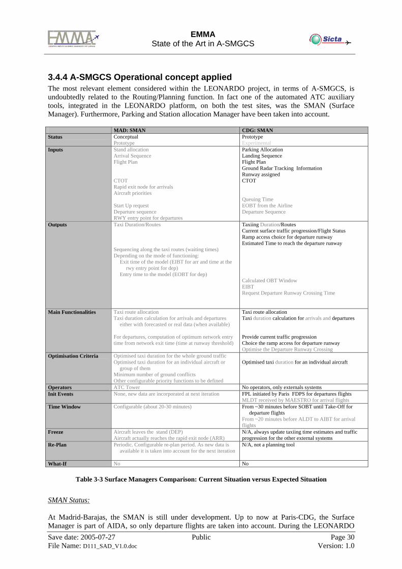
EMMA
State of the Art in A-SMGCS
Save date: 2005-07-27 Public Page 30 File Name: D111_SAD_V1.0.doc Version: 1.0
3.4.4 A-SMGCS Operational concept applied The most relevant element considered within the LEONARDO project, in terms of A-SMGCS, is undoubtedly related to the Routing/Planning function. In fact one of the automated ATC auxiliary tools, integrated in the LEONARDO platform, on both the test sites, was the SMAN (Surface Manager). Furthermore, Parking and Station allocation Manager have been taken into account.
MAD: SMAN CDG: SMAN Status Conceptual
Prototype Prototype Experimental
Inputs Stand allocation Arrival Sequence Flight Plan CTOT Rapid exit node for arrivals Aircraft priorities Start Up request Departure sequence RWY entry point for departures
Parking Allocation Landing Sequence Flight Plan Ground Radar Tracking Information Runway assigned CTOT Queuing Time EOBT from the Airline Departure Sequence
Outputs Taxi Duration/Routes Sequencing along the taxi routes (waiting times) Depending on the mode of functioning:
Exit time of the model (EIBT for arr and time at the rwy entry point for dep)
Entry time to the model (EOBT for dep)
Taxiing Duration/Routes Current surface traffic progression/Flight Status Ramp access choice for departure runway Estimated Time to reach the departure runway Calculated OBT Window EIBT Request Departure Runway Crossing Time
Main Functionalities Taxi route allocation Taxi duration calculation for arrivals and departures
either with forecasted or real data (when available) For departures, computation of optimum network entry time from network exit time (time at runway threshold)
Taxi route allocation Taxi duration calculation for arrivals and departures Provide current traffic progression Choice the ramp access for departure runway Optimise the Departure Runway Crossing
Optimisation Criteria Optimised taxi duration for the whole ground traffic Optimised taxi duration for an individual aircraft or
group of them Minimum number of ground conflicts Other configurable priority functions to be defined
Optimised taxi duration for an individual aircraft
Operators ATC Tower No operators, only externals systems Init Events None, new data are incorporated at next iteration FPL initiated by Paris FDPS for departures flights
MLDT received by MAESTRO for arrival flights Time Window Configurable (about 20-30 minutes) From ~30 minutes before SOBT until Take-Off for
departure flights From ~20 minutes before ALDT to AIBT for arrival flights
Freeze Aircraft leaves the stand (DEP) Aircraft actually reaches the rapid exit node (ARR)
N/A, always update taxiing time estimates and traffic progression for the other external systems
Re-Plan Periodic. Configurable re-plan period. As new data is available it is taken into account for the next iteration
N/A, not a planning tool
What-If No No
Table 3-3 Surface Managers Comparison: Current Situation versus Expected Situation
SMAN Status: At Madrid-Barajas, the SMAN is still under development. Up to now at Paris-CDG, the Surface Manager is part of AIDA, so only departure flights are taken into account. During the LEONARDO
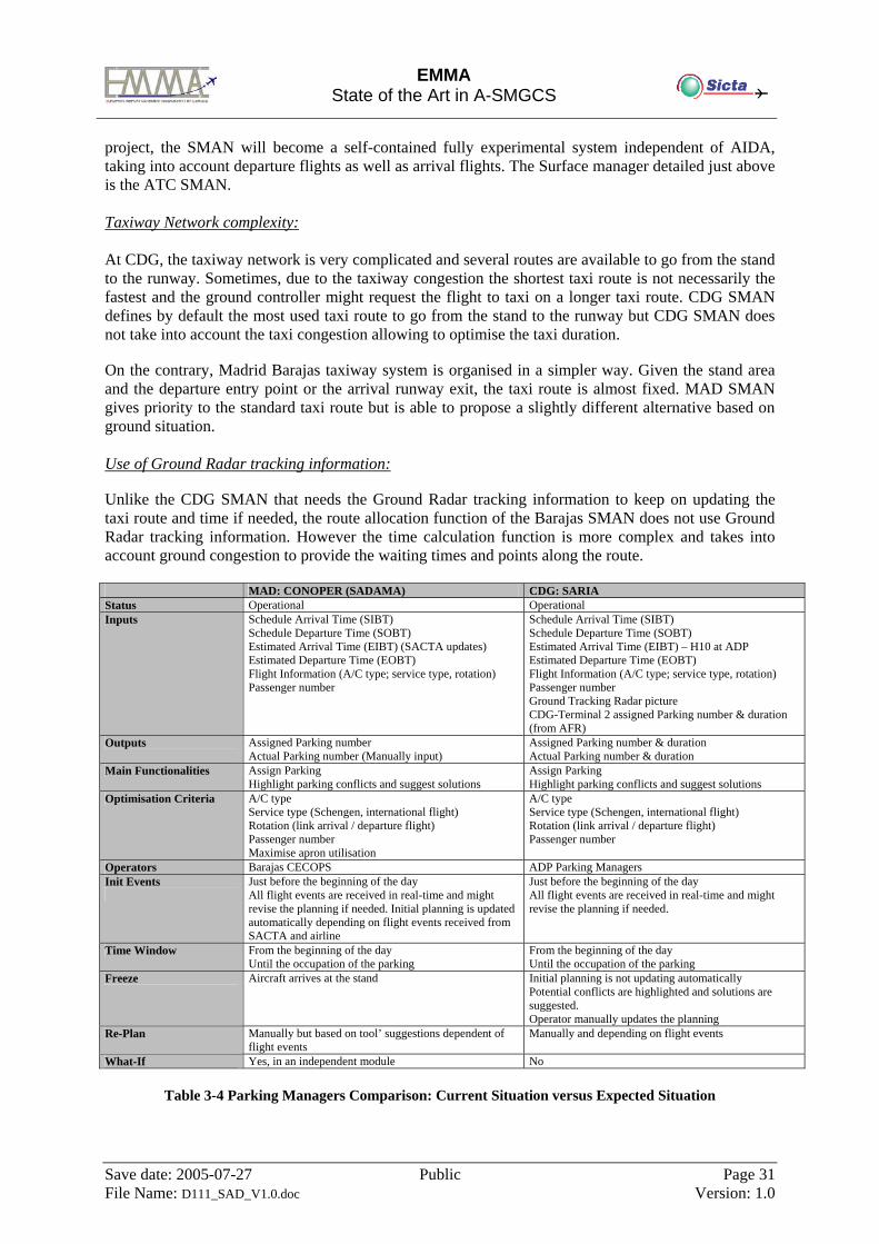
EMMA
State of the Art in A-SMGCS
Save date: 2005-07-27 Public Page 31 File Name: D111_SAD_V1.0.doc Version: 1.0
project, the SMAN will become a self-contained fully experimental system independent of AIDA, taking into account departure flights as well as arrival flights. The Surface manager detailed just above is the ATC SMAN. Taxiway Network complexity:
At CDG, the taxiway network is very complicated and several routes are available to go from the stand to the runway. Sometimes, due to the taxiway congestion the shortest taxi route is not necessarily the fastest and the ground controller might request the flight to taxi on a longer taxi route. CDG SMAN defines by default the most used taxi route to go from the stand to the runway but CDG SMAN does not take into account the taxi congestion allowing to optimise the taxi duration.
On the contrary, Madrid Barajas taxiway system is organised in a simpler way. Given the stand area
and the departure entry point or the arrival runway exit, the taxi route is almost fixed. MAD SMAN gives priority to the standard taxi route but is able to propose a slightly different alternative based on ground situation.
Use of Ground Radar tracking information:
Unlike the CDG SMAN that needs the Ground Radar tracking information to keep on updating the
taxi route and time if needed, the route allocation function of the Barajas SMAN does not use Ground Radar tracking information. However the time calculation function is more complex and takes into account ground congestion to provide the waiting times and points along the route.
MAD: CONOPER (SADAMA) CDG: SARIA Status Operational Operational Inputs Schedule Arrival Time (SIBT)
Schedule Departure Time (SOBT) Estimated Arrival Time (EIBT) (SACTA updates) Estimated Departure Time (EOBT) Flight Information (A/C type; service type, rotation) Passenger number
Schedule Arrival Time (SIBT) Schedule Departure Time (SOBT) Estimated Arrival Time (EIBT) – H10 at ADP Estimated Departure Time (EOBT) Flight Information (A/C type; service type, rotation) Passenger number Ground Tracking Radar picture CDG-Terminal 2 assigned Parking number & duration (from AFR)
Outputs Assigned Parking number Actual Parking number (Manually input)
Assigned Parking number & duration Actual Parking number & duration
Main Functionalities Assign Parking Highlight parking conflicts and suggest solutions
Assign Parking Highlight parking conflicts and suggest solutions
Optimisation Criteria A/C type Service type (Schengen, international flight) Rotation (link arrival / departure flight) Passenger number Maximise apron utilisation
A/C type Service type (Schengen, international flight) Rotation (link arrival / departure flight) Passenger number
Operators Barajas CECOPS ADP Parking Managers Init Events
Just before the beginning of the day All flight events are received in real-time and might revise the planning if needed. Initial planning is updated automatically depending on flight events received from SACTA and airline
Just before the beginning of the day All flight events are received in real-time and might revise the planning if needed.
Time Window From the beginning of the day Until the occupation of the parking
From the beginning of the day Until the occupation of the parking
Freeze Aircraft arrives at the stand Initial planning is not updating automatically Potential conflicts are highlighted and solutions are suggested. Operator manually updates the planning
Re-Plan Manually but based on tool’ suggestions dependent of flight events
Manually and depending on flight events
What-If Yes, in an independent module No
Table 3-4 Parking Managers Comparison: Current Situation versus Expected Situation
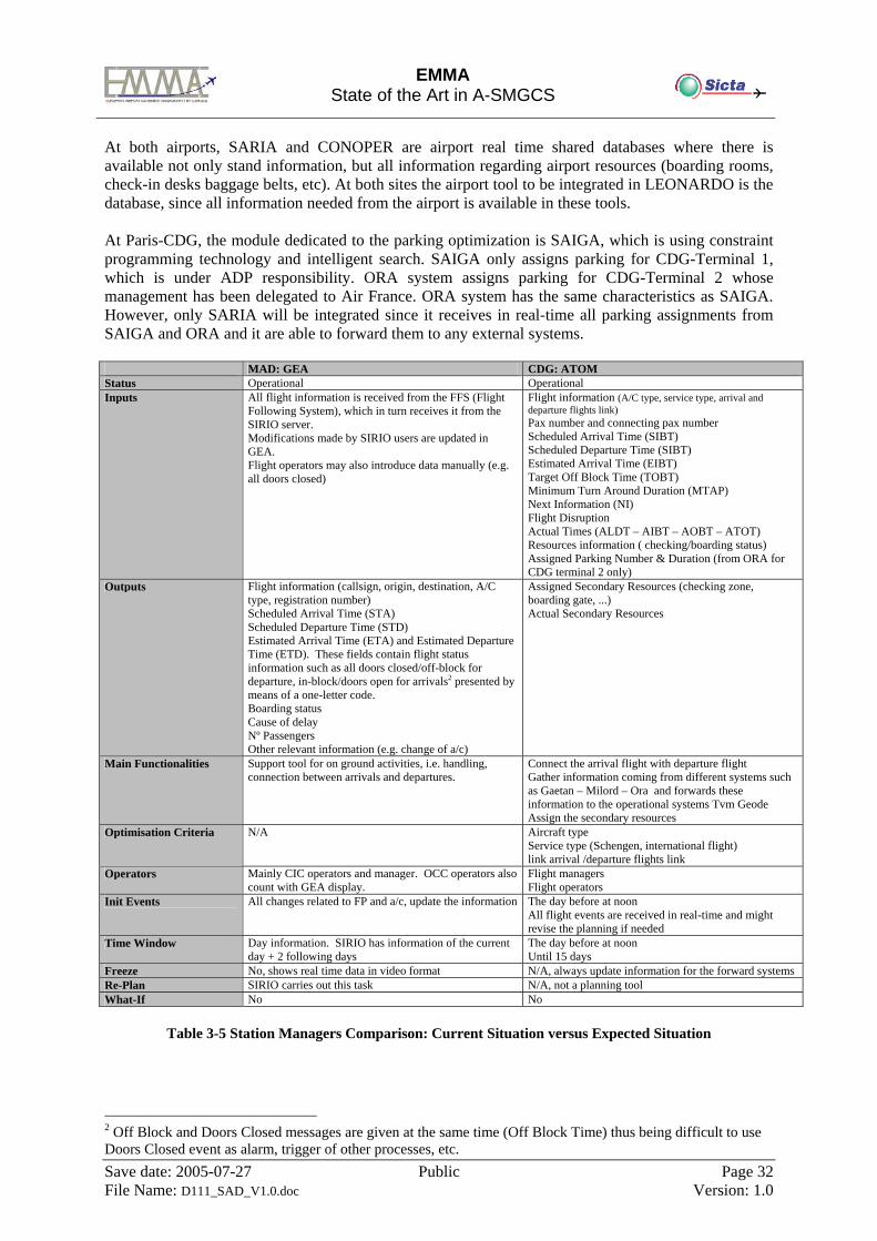
EMMA
State of the Art in A-SMGCS
Save date: 2005-07-27 Public Page 32 File Name: D111_SAD_V1.0.doc Version: 1.0
At both airports, SARIA and CONOPER are airport real time shared databases where there is available not only stand information, but all information regarding airport resources (boarding rooms, check-in desks baggage belts, etc). At both sites the airport tool to be integrated in LEONARDO is the database, since all information needed from the airport is available in these tools. At Paris-CDG, the module dedicated to the parking optimization is SAIGA, which is using constraint programming technology and intelligent search. SAIGA only assigns parking for CDG-Terminal 1, which is under ADP responsibility. ORA system assigns parking for CDG-Terminal 2 whose management has been delegated to Air France. ORA system has the same characteristics as SAIGA. However, only SARIA will be integrated since it receives in real-time all parking assignments from SAIGA and ORA and it are able to forward them to any external systems. MAD: GEA CDG: ATOM Status Operational Operational Inputs All flight information is received from the FFS (Flight
Following System), which in turn receives it from the SIRIO server. Modifications made by SIRIO users are updated in GEA. Flight operators may also introduce data manually (e.g. all doors closed)
Flight information (A/C type, service type, arrival and departure flights link) Pax number and connecting pax number Scheduled Arrival Time (SIBT) Scheduled Departure Time (SIBT) Estimated Arrival Time (EIBT) Target Off Block Time (TOBT) Minimum Turn Around Duration (MTAP) Next Information (NI) Flight Disruption Actual Times (ALDT – AIBT – AOBT – ATOT) Resources information ( checking/boarding status) Assigned Parking Number & Duration (from ORA for CDG terminal 2 only)
Outputs Flight information (callsign, origin, destination, A/C type, registration number) Scheduled Arrival Time (STA) Scheduled Departure Time (STD) Estimated Arrival Time (ETA) and Estimated Departure Time (ETD). These fields contain flight status information such as all doors closed/off-block for departure, in-block/doors open for arrivals2 presented by means of a one-letter code. Boarding status Cause of delay Nº Passengers Other relevant information (e.g. change of a/c)
Assigned Secondary Resources (checking zone, boarding gate, ...) Actual Secondary Resources
Main Functionalities Support tool for on ground activities, i.e. handling, connection between arrivals and departures.
Connect the arrival flight with departure flight Gather information coming from different systems such as Gaetan – Milord – Ora and forwards these information to the operational systems Tvm Geode Assign the secondary resources
Optimisation Criteria N/A Aircraft type Service type (Schengen, international flight) link arrival /departure flights link
Operators Mainly CIC operators and manager. OCC operators also count with GEA display.
Flight managers Flight operators
Init Events All changes related to FP and a/c, update the information The day before at noon All flight events are received in real-time and might revise the planning if needed
Time Window Day information. SIRIO has information of the current day + 2 following days
The day before at noon Until 15 days
Freeze No, shows real time data in video format N/A, always update information for the forward systems Re-Plan SIRIO carries out this task N/A, not a planning tool What-If No No
Table 3-5 Station Managers Comparison: Current Situation versus Expected Situation
2 Off Block and Doors Closed messages are given at the same time (Off Block Time) thus being difficult to use Doors Closed event as alarm, trigger of other processes, etc.
EMMA
State of the Art in A-SMGCS
Save date: 2005-07-27 Public Page 33 File Name: D111_SAD_V1.0.doc Version: 1.0
3.4.5 Useful considerations for EMMA Concept Some of the Applications involving SMAN tool and tested within the LEONARDO Project should be taken into account during the Emma2 project, when Planning and Routing functions are going to be considered in a more significant way. The Applications that should be considered relevant for EMMA are set out below:
o Estimation of the In-Block Time o Estimation of the Off-Block Time o Estimation of the Take-Off Time
All the public documentations produced inside the LEONARDO Project are available on the LEONARDO web site [18]
3.5 A-SMGCS at Paris CDG airport
3.5.1 General description of the airport
3.5.1.1 Traffic Paris–Charles-de-Gaulle is the largest airport in France, and the first in Europe for aircraft movements. It is the 8th airport in the world for passenger traffic. In 2001 it had 48 million passengers, and 592 000 aircraft operations. Peak day in 2000: August 31 - 1662 aircraft movements (departures and arrivals). Paris–Charles-de-Gaulle is located in the North-East of Paris City, at about 40 km. Very near this airport, stands Le Bourget airport, which specialises in general aviation (corporate travel) and taxi flights: 50 000 IFR and 10 000 VFR flights in 2001 In the south of the city is Paris’ other large commercial airport: Orly. • 25 million passengers • 250 000 flights They are all part of the large Paris TMA, and the ATC operations are handled by two approach centres, one in each airport.
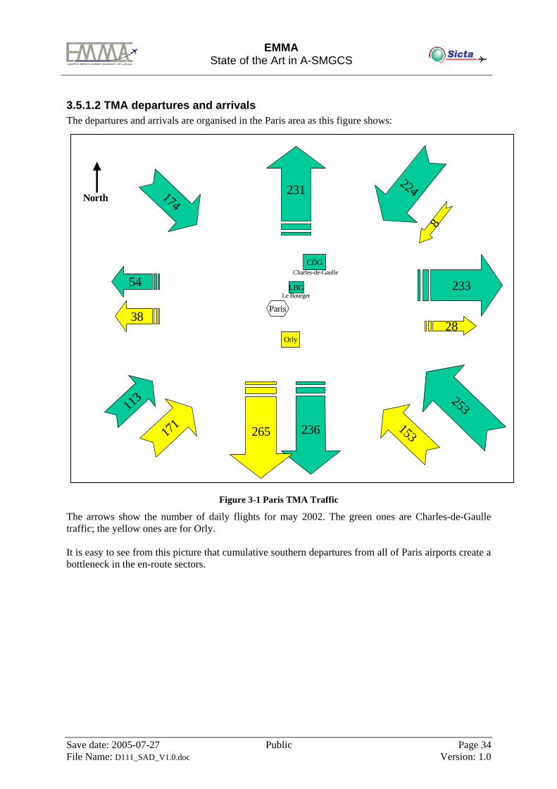
EMMA
State of the Art in A-SMGCS
Save date: 2005-07-27 Public Page 34 File Name: D111_SAD_V1.0.doc Version: 1.0
3.5.1.2 TMA departures and arrivals The departures and arrivals are organised in the Paris area as this figure shows:
Figure 3-1 Paris TMA Traffic
The arrows show the number of daily flights for may 2002. The green ones are Charles-de-Gaulle traffic; the yellow ones are for Orly. It is easy to see from this picture that cumulative southern departures from all of Paris airports create a bottleneck in the en-route sectors.
174
Paris
Orly
CDG
LBG
224
253113
171 153
231
233
236
54
3828
2658
Charles-de-Gaulle
Le Bourget
North
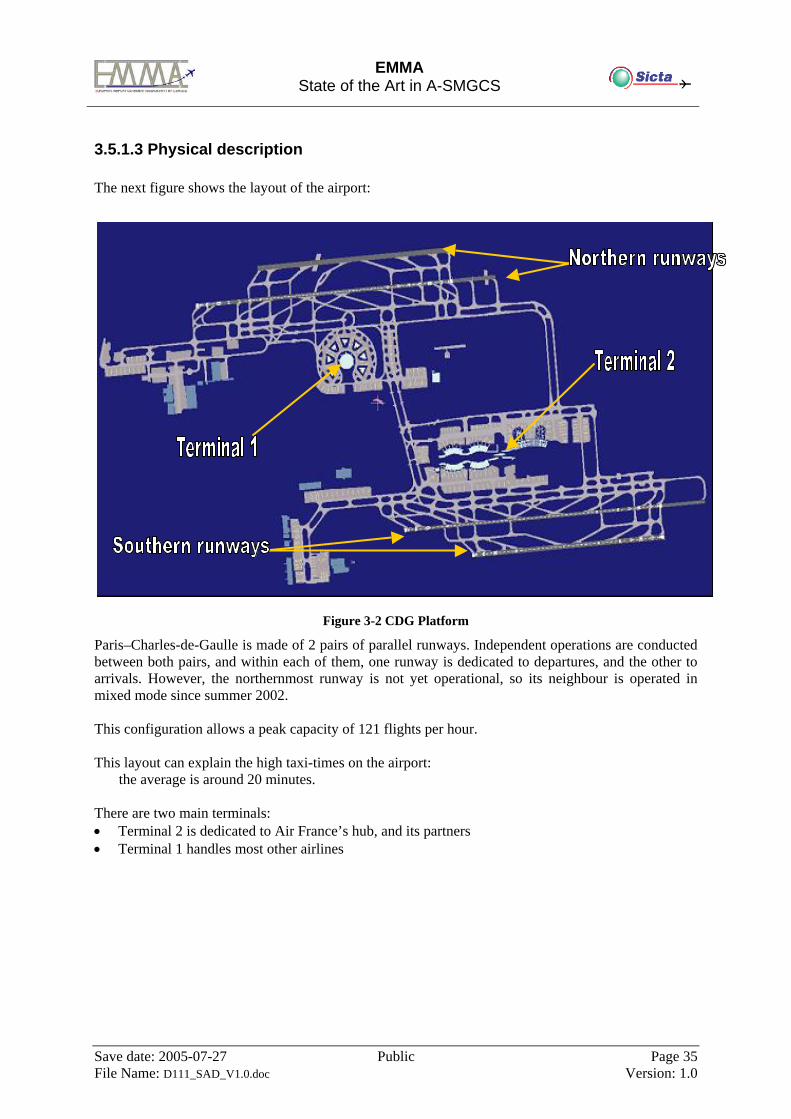
EMMA
State of the Art in A-SMGCS
Save date: 2005-07-27 Public Page 35 File Name: D111_SAD_V1.0.doc Version: 1.0
3.5.1.3 Physical description The next figure shows the layout of the airport:
Figure 3-2 CDG Platform
Paris–Charles-de-Gaulle is made of 2 pairs of parallel runways. Independent operations are conducted between both pairs, and within each of them, one runway is dedicated to departures, and the other to arrivals. However, the northernmost runway is not yet operational, so its neighbour is operated in mixed mode since summer 2002. This configuration allows a peak capacity of 121 flights per hour. This layout can explain the high taxi-times on the airport:
the average is around 20 minutes. There are two main terminals: • Terminal 2 is dedicated to Air France’s hub, and its partners • Terminal 1 handles most other airlines
EMMA
State of the Art in A-SMGCS
Save date: 2005-07-27 Public Page 36 File Name: D111_SAD_V1.0.doc Version: 1.0
3.5.2 ATC operational context
3.5.2.1 Description 3 different centres control air Traffic in the Paris area: • the Paris ATCC in charge of flights between the TMAs and the en-route phase • the Paris-Charles-de-Gaulle Approach control centre, responsible for the northern part of Paris
TMA, dealing with approach for Charles-de-Gaulle and Le Bourget airports • the Orly Approach control centre, responsible for the southern part of Paris TMA, dealing with
approach for Orly, Toussus and Villacoublay airports The two approaches, being closely linked, have to assume control for some flights that pass through their airspace coming from or going to airports on the other side. Charles-de-Gaulle airport is made of 4 runways. They are all east-west oriented, and organized as 2 sets of 2 parallel runways. Both sets are completely independent. Within each set, the inner runway is dedicated to departures; the outer runway is dedicated to arrivals. Operations around the airport tend to be more and more separated between two geographical independent parts. The northern part is made of north runways, north arrivals, terminal 1 and its taxiways. The southern part is made of south runways, south arrivals, terminal 2 and its taxiways (see figure 1). On Paris-Charles-de-Gaulle airport, one approach room and two control towers, north and south, share responsibility for the area. In each of them, several Air Traffic Controllers working positions can be found. The Approach Room a) The COOR-INI The COOR-INI is responsible for data and telephone co-ordination between the ATCC arrival sectors and the INI positions. He manages transfer conditions with the ATCC planning controllers, writes this information down on the flight paper strip, along with Estimated Approach Time. He then delivers the strips to the appropriate INI controller. b) The INI The 2 INI, or initial controllers, assume control of arrival flights since the Initial Approach Fixes. They share the airspace as North and South areas. The North INI deals with aircraft coming from the North-East and North-West IAFs, the South INI deals with aircraft coming from the South-East and South -West IAFs. They take care of backwind procedures, and merge their two streams into a single one, then deliver it to the ITM. They also interchange flights that need to land on the opposite runway. c) The ITM The 2 ITM, or intermediate controllers, each handle one of the 2 streams of arrivals, and directs it to the ILS capture and the landing runway. d) The SEQ
EMMA
State of the Art in A-SMGCS
Save date: 2005-07-27 Public Page 37 File Name: D111_SAD_V1.0.doc Version: 1.0
The SEQ, or sequencer, is responsible for preparing the arrival sequences for both landing runways, plus the Le Bourget arrivals. All this is currently done with the Arrival Manager tool MAESTRO. The SEQ checks the tool’s propositions, makes the necessary arrangements, co-ordinates with the ATCC planning controllers the necessary speed reductions to avoid holding patterns. He balances traffic loads between both runways and optimizes the use of capacity. e) The DEP The DEP or departure controller takes control over flights right after take off. He directs them along their SID, spacing them out in order to deliver them properly to the ATCC. The North and South Towers
a) The PVL The PVL (or pre-departure controller), located in the north Tower, is responsible for delivering the Pre Departure Clearance. The PVL controller in the north tower is in charge of clearances for all departures on the airport. After receiving a request from the pilot, either on the frequency or by data-link message, about 10 minutes before the planned off-block, he first checks compliance with the ATFM slot. If correct, he will determine the departure runway and the SID, and input them in the system. He tries to balance traffic between both departure runways, and prevent overloads either on the ground or in the air. According to all this, he will then deliver authorization to start-up engines.
b) The VA The VA or Annex Control Cab is specific to the south tower and terminal 2. It is responsible for apron traffic management. There can be up to 3 apron controllers in the VA. They give pushback clearances, direct departures to the apron exits and hand them over to ground control (SOL). They take control of arrivals around apron entry points and direct them to the gates. They manage holding for multiple pushback or apron congestion.
c) The SOL The SOL, or ground controllers are in charge of ground movement on the airport. There can be up to 3 ground controllers, with geographical separation of their areas of responsibility: one, for the northern terminals and taxiways, two for the southern terminals and taxiways, sharing it as east and west areas. The north and south parts are linked by two high-speed taxiways, where ground controllers hand traffic over. The north SOL gives the pushback or auto-departure clearance and checks the operations. He determines ground routing for departures and arrivals in the area, and directs pilots along these, managing crossings and conflicts. He organizes the departure sequence for the north runway, and assigns the runway entries, then hands the traffic over to the LOC. He manages arrivals up to the gate, including holding for gate availability, or apron congestion. The 2 south ground controllers are in charge of ground movement on the south taxiways, between apron and runway. One takes care of arrivals, after crossing of the departure runway up to the apron entries. The other organizes the departure sequence from apron exits to runway entries.
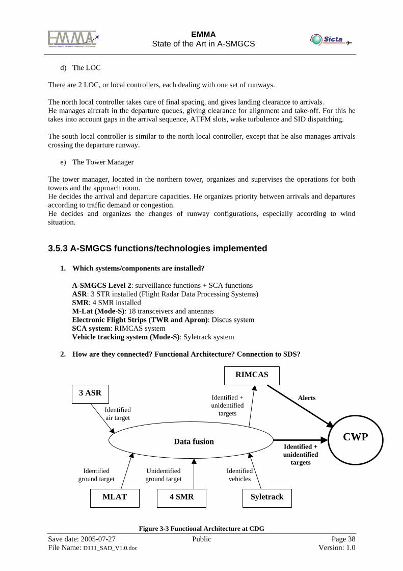
EMMA
State of the Art in A-SMGCS
Save date: 2005-07-27 Public Page 38 File Name: D111_SAD_V1.0.doc Version: 1.0
d) The LOC There are 2 LOC, or local controllers, each dealing with one set of runways. The north local controller takes care of final spacing, and gives landing clearance to arrivals. He manages aircraft in the departure queues, giving clearance for alignment and take-off. For this he takes into account gaps in the arrival sequence, ATFM slots, wake turbulence and SID dispatching. The south local controller is similar to the north local controller, except that he also manages arrivals crossing the departure runway.
e) The Tower Manager The tower manager, located in the northern tower, organizes and supervises the operations for both towers and the approach room. He decides the arrival and departure capacities. He organizes priority between arrivals and departures according to traffic demand or congestion. He decides and organizes the changes of runway configurations, especially according to wind situation.
3.5.3 A-SMGCS functions/technologies implemented
1. Which systems/components are installed? A-SMGCS Level 2: surveillance functions + SCA functions ASR: 3 STR installed (Flight Radar Data Processing Systems) SMR: 4 SMR installed M-Lat (Mode-S): 18 transceivers and antennas Electronic Flight Strips (TWR and Apron): Discus system SCA system: RIMCAS system Vehicle tracking system (Mode-S): Syletrack system
2. How are they connected? Functional Architecture? Connection to SDS?
3 ASR
Identified air target
Identified ground target
MLAT 4 SMR Syletrack
Unidentified ground target
Identified vehicles
Data fusion
RIMCAS
CWPIdentified + unidentified
targets
Identified + unidentified
targets
Alerts
Figure 3-3 Functional Architecture at CDG
EMMA
State of the Art in A-SMGCS
Save date: 2005-07-27 Public Page 39 File Name: D111_SAD_V1.0.doc Version: 1.0
3. Which systems/functions are proofed/certified?
At the present time, there is no certification process for ATC tools. However, all systems have verified and validated by ADP and STNA (DNA technical services) before use in an operational context
4. Are they reliable?
All systems are reliable: it is one of the criteria in the V&V process performed by ADP and STNA. All systems are available 24h a day. The redundancy of the system and of the sensors guarantees their availability.
5. Existing Problems (which may be solved due to A-SMGCS EMMA)?
In order to improve RIMCAS system, it is necessary to make the input surveillance data more reliable. False detection (fixed plot, grass, etc.) generate false alerts, which may have an impact on controller workload. EMMA project WP1.1 will help identify the main causes of false detection and false alerts and give recommendations for the improvement of the system.
6. Data Resources – information flow between ACC –APP- TWR – Aprons –Airlines- Airport- etc.
The following picture show the relationship between the airport partners (ACC-APP and TWR considered as a whole) (it is taken from Leonardo project: it is not A-SMGCS oriented, but there is few A-SMGCS information flows between airport partners. Relationships between ATC positions are explained in the other document)
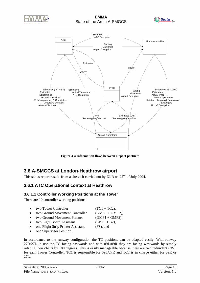
EMMA
State of the Art in A-SMGCS
Save date: 2005-07-27 Public Page 40 File Name: D111_SAD_V1.0.doc Version: 1.0
Figure 3-4 Information flows between airport partners
3.6 A-SMGCS at London-Heathrow airport This status report results from a site visit carried out by DLR on 22nd of July 2004.
3.6.1 ATC Operational context at Heathrow
3.6.1.1 Controller Working Positions at the Tower There are 10 controller working positions:
• two Tower Controller (TC1 + TC2), • two Ground Movement Controller (GMC1 + GMC2), • two Ground Movement Planner (GMP1 + GMP2), • two Light Board Assistant (LB1 + LB2), • one Flight Strip Printer Assistant (FS), and • one Supervisor Position
In accordance to the runway configuration the TC positions can be adapted easily. With runway 27R/27L in use the TC facing eastwards and with 09L/09R they are facing westwards by simply rotating their chairs by 180 degrees. This is easily manageable because there are two redundant CWP for each Tower Controller. TC1 is responsible for 09L/27R and TC2 is in charge either for 09R or 27L.
ATC ATC Airport Authorities
Aircraft Operators/ H dl
Aircraft Operators/
ATFM
CTOT
Estimates (OBT)Slot swapping/revision
Estimates ( O GO G )
ParkingGate state
Airport Disruption f
Estimates ( GO G )ATC Disruption
I f i
Schedules (IBT,OBT)Estimates ( O )Actual times
( O )Ground operations Rotation planning & Cumulative
PassangersAircraft Disruption
f
Schedules (IBT,OBT) Estimates ( O )Actual times
( O )Ground operations Rotation planning & Cumulative
Departure priorities Aircraft Disruption
f
CTOT
CTOTSlot swapping/revision
Estimates (LDT IBT TOT GOP GIP)Arrival/Departure
CATC Disruption I f i
ParkingGate state
Airport Disruption I f i
EMMA
State of the Art in A-SMGCS
Save date: 2005-07-27 Public Page 41 File Name: D111_SAD_V1.0.doc Version: 1.0
With the Ground Movement Controller (GMC) and also the Light Board Assistants (LB) share the responsibility of the movements on the aerodrome: GMC1 and LB1 are responsible for northwest part whereas GMC2 and LB2 are responsible for the southeast part. With this work share it could happen that for a single flight 6 handover have to be performed. However, NATS controllers are used to it and estimate it very uncritical. The Ground Movement Planner (GMP) grants the departure clearance including SID, SSR Code, ATIS, RWY, und Start up Clearance. The GMP aims to establish the best sequence by granting the start-up clearance by close co-ordination with the Ground Movement Controller. All positions, except of LB and FS are equipped with A-SMGCS display.
3.6.1.2 Adjacent Information Centres Gate Management The aerodrome movement control is completely performed by NATS from their Control Tower. There is a local Gate Management Centre that is managed by the Airport itself. The Gate Management has very close contact to the airlines to enable a very flexible gate allocation. Co-operations between NATS and the Gate Management are very loose as NATS is only interested in the result of the gate allocation process. Approach Control The Approach Centre is not situated at the airport but 1,5km away the airport. The arrival flight strips are printed out at the Tower 40 minutes in advance. They have no access to A-SMGCS information. Departure Control They are connected to the A-SMGCS – they are provided with the pushback event that helps them to manage the real capacity demand more in advance.
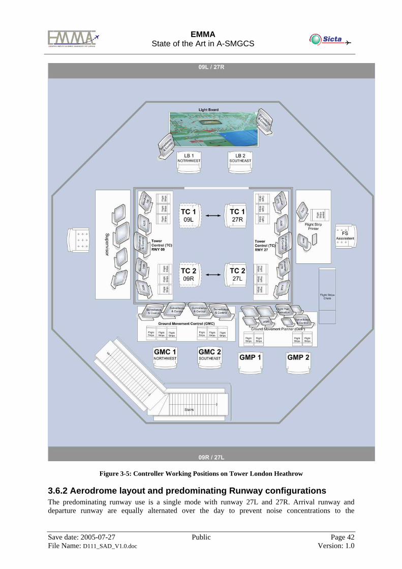
EMMA
State of the Art in A-SMGCS
Save date: 2005-07-27 Public Page 42 File Name: D111_SAD_V1.0.doc Version: 1.0
Figure 3-5: Controller Working Positions on Tower London Heathrow
3.6.2 Aerodrome layout and predominating Runway configurations The predominating runway use is a single mode with runway 27L and 27R. Arrival runway and departure runway are equally alternated over the day to prevent noise concentrations to the
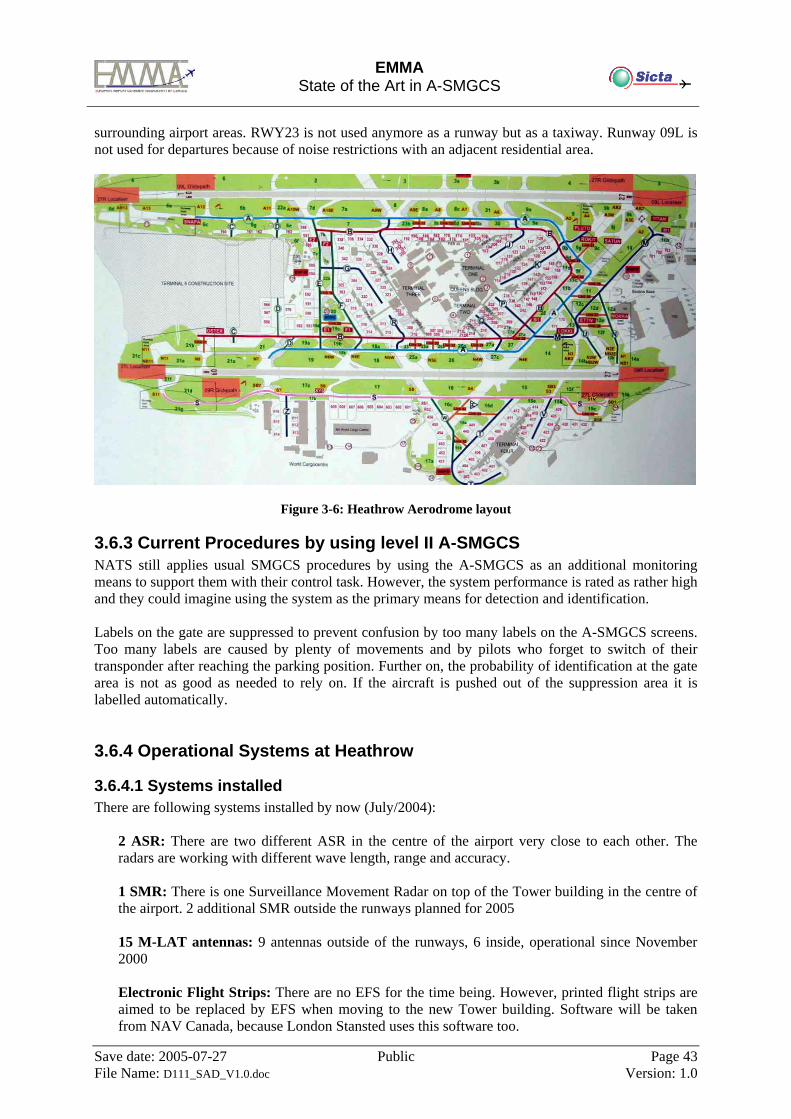
EMMA
State of the Art in A-SMGCS
Save date: 2005-07-27 Public Page 43 File Name: D111_SAD_V1.0.doc Version: 1.0
surrounding airport areas. RWY23 is not used anymore as a runway but as a taxiway. Runway 09L is not used for departures because of noise restrictions with an adjacent residential area.
Figure 3-6: Heathrow Aerodrome layout
3.6.3 Current Procedures by using level II A-SMGCS NATS still applies usual SMGCS procedures by using the A-SMGCS as an additional monitoring means to support them with their control task. However, the system performance is rated as rather high and they could imagine using the system as the primary means for detection and identification. Labels on the gate are suppressed to prevent confusion by too many labels on the A-SMGCS screens. Too many labels are caused by plenty of movements and by pilots who forget to switch of their transponder after reaching the parking position. Further on, the probability of identification at the gate area is not as good as needed to rely on. If the aircraft is pushed out of the suppression area it is labelled automatically.
3.6.4 Operational Systems at Heathrow
3.6.4.1 Systems installed There are following systems installed by now (July/2004):
2 ASR: There are two different ASR in the centre of the airport very close to each other. The radars are working with different wave length, range and accuracy. 1 SMR: There is one Surveillance Movement Radar on top of the Tower building in the centre of the airport. 2 additional SMR outside the runways planned for 2005 15 M-LAT antennas: 9 antennas outside of the runways, 6 inside, operational since November 2000 Electronic Flight Strips: There are no EFS for the time being. However, printed flight strips are aimed to be replaced by EFS when moving to the new Tower building. Software will be taken from NAV Canada, because London Stansted uses this software too.
EMMA
State of the Art in A-SMGCS
Save date: 2005-07-27 Public Page 44 File Name: D111_SAD_V1.0.doc Version: 1.0
SDS: The output of the surveillance data server is one position report per second. The incoming sensor information is weighted differently, e.g. MLAT is more significant than SMR information and SMR information are even suppressed with the alerting function. The SMR information is displayed to the ATCO without any filtering. The SDS is operational since November 2002.
Vehicle tracking system (Mode-S): Very less vehicles equipped, i.e. there are also unequipped
vehicles on the runway. At the moment they investigate the performance and the potential benefit of vehicles equipped with co-operative sensors. In case of positive results they want to equip more vehicles
RIMCAS: For the moment the system is only used as an additional assistance system or an
additional safety net. The system is not adapted to different visibility conditions.
3.6.4.2 System Performance Surveillance Surveillance performance has not been measured objectively but it is estimated very high by the controllers. With the A-SMGCS display an algorithm has been established that prevents an overlapping of labels what is absolutely needed with the mass of departures. There is only one SMR on the top of the Tower building, so that the surrounding terminals cause shadows which impair the detection of non-cooperative target. With these areas only detection of co-operative targets is possible (MLAT). Further on, buildings and parking aircraft cause shadows on the runways that appear as false targets occasionally. These surveillance lacks shall be treated with two additional SMRs that are built up in the centre outside the runways in 2005. ADS-B receiver is installed but not used due to interferences with ASR und SMR when processed by the SDS. Further on, inaccuracy with the sensor is assumed. NATS would estimate that 10 to 15 percent of aircraft operating on London Heathrow are ADS-B equipped. The correct transponder operating procedures of the aircraft, as described with the Eurocontrol AIC, is regarded by the pilots by nearly 100%. If the transponder has not been set correctly, the controllers request the right transponder setting via radio. Alerting System Controllers are very satisfied with the RWY incursion alerting function (RIMCAS). The alerts are bounded to runway incursions only; there is neither a prediction nor taxiway conflict detection. Since the alerting performance is dependent on the quality of the surveillance they have also many false/unwanted targets that evoke unwanted alerts. False alerts are very disturbing at night and in LVC because they can hardly be verified or falsified by looking out of the window. Also double targets during take off that are caused by the same aircraft, are observed and release false alerts. That’s why NATS decided that the alerting function only bases on co-operative targets. Missed alerts, that is, a real conflict situation that has not been detected by the alert function, has never been observed.
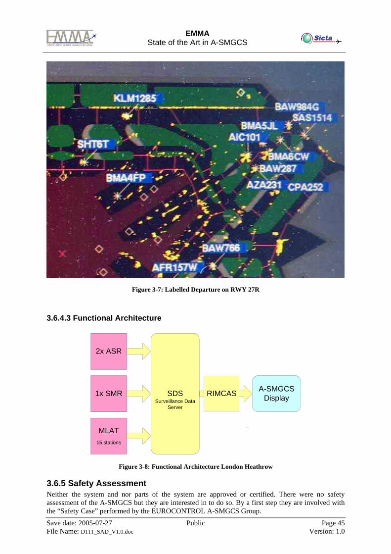
EMMA
State of the Art in A-SMGCS
Save date: 2005-07-27 Public Page 45 File Name: D111_SAD_V1.0.doc Version: 1.0
Figure 3-7: Labelled Departure on RWY 27R
3.6.4.3 Functional Architecture
1x SMR
MLAT15 stations
2x ASR
A-SMGCS DisplaySDS
Surveillance Data Server
...
RIMCAS
Figure 3-8: Functional Architecture London Heathrow
3.6.5 Safety Assessment Neither the system and nor parts of the system are approved or certified. There were no safety assessment of the A-SMGCS but they are interested in to do so. By a first step they are involved with the “Safety Case” performed by the EUROCONTROL A-SMGCS Group.
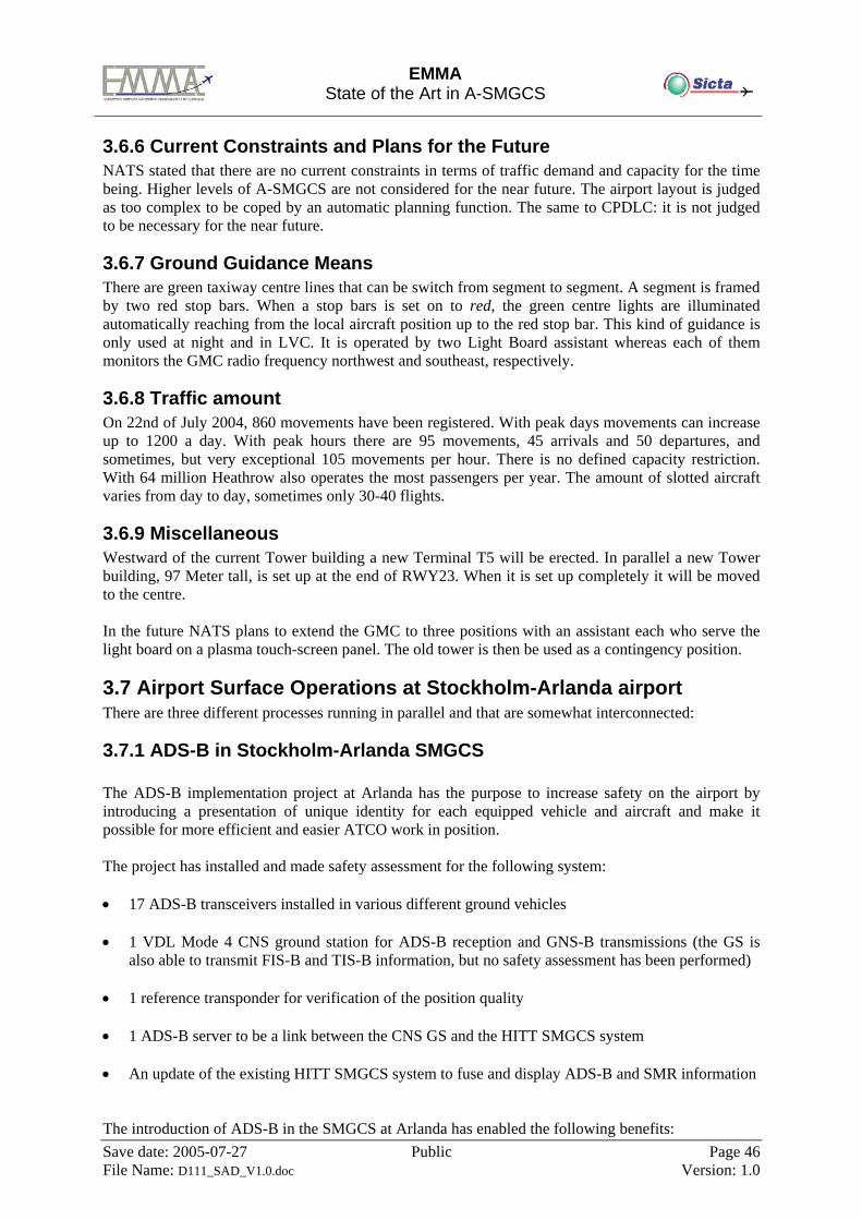
EMMA
State of the Art in A-SMGCS
Save date: 2005-07-27 Public Page 46 File Name: D111_SAD_V1.0.doc Version: 1.0
3.6.6 Current Constraints and Plans for the Future NATS stated that there are no current constraints in terms of traffic demand and capacity for the time being. Higher levels of A-SMGCS are not considered for the near future. The airport layout is judged as too complex to be coped by an automatic planning function. The same to CPDLC: it is not judged to be necessary for the near future.
3.6.7 Ground Guidance Means There are green taxiway centre lines that can be switch from segment to segment. A segment is framed by two red stop bars. When a stop bars is set on to red, the green centre lights are illuminated automatically reaching from the local aircraft position up to the red stop bar. This kind of guidance is only used at night and in LVC. It is operated by two Light Board assistant whereas each of them monitors the GMC radio frequency northwest and southeast, respectively.
3.6.8 Traffic amount On 22nd of July 2004, 860 movements have been registered. With peak days movements can increase up to 1200 a day. With peak hours there are 95 movements, 45 arrivals and 50 departures, and sometimes, but very exceptional 105 movements per hour. There is no defined capacity restriction. With 64 million Heathrow also operates the most passengers per year. The amount of slotted aircraft varies from day to day, sometimes only 30-40 flights.
3.6.9 Miscellaneous Westward of the current Tower building a new Terminal T5 will be erected. In parallel a new Tower building, 97 Meter tall, is set up at the end of RWY23. When it is set up completely it will be moved to the centre. In the future NATS plans to extend the GMC to three positions with an assistant each who serve the light board on a plasma touch-screen panel. The old tower is then be used as a contingency position.
3.7 Airport Surface Operations at Stockholm-Arlanda airport There are three different processes running in parallel and that are somewhat interconnected:
3.7.1 ADS-B in Stockholm-Arlanda SMGCS The ADS-B implementation project at Arlanda has the purpose to increase safety on the airport by introducing a presentation of unique identity for each equipped vehicle and aircraft and make it possible for more efficient and easier ATCO work in position. The project has installed and made safety assessment for the following system: • 17 ADS-B transceivers installed in various different ground vehicles • 1 VDL Mode 4 CNS ground station for ADS-B reception and GNS-B transmissions (the GS is
also able to transmit FIS-B and TIS-B information, but no safety assessment has been performed) • 1 reference transponder for verification of the position quality • 1 ADS-B server to be a link between the CNS GS and the HITT SMGCS system • An update of the existing HITT SMGCS system to fuse and display ADS-B and SMR information The introduction of ADS-B in the SMGCS at Arlanda has enabled the following benefits:
EMMA
State of the Art in A-SMGCS
Save date: 2005-07-27 Public Page 47 File Name: D111_SAD_V1.0.doc Version: 1.0
1) Labelling for vehicles that had none earlier, 2) Improvement of surveillance coverage 3) Automatic coupling to flight plan Initially there are no major changes in the regulation and the same working methodology is still valid for an SMR and ADS-B environment. In future scenario new procedures enabling more benefits for the ATCO can be used including the use the labels from a transceiver-based system. A prerequisite is that the majority of the vehicles and A/C are equipped and that thorough validation and safety assessments are performed. The validation activities and gained experience will show the correctness of the labels and the capability of the system components. If the experience is good the use of positive tagging as a means of detection can be used operationally.
3.7.2 Airport Bus Coordination System at Stockholm-Arlanda airport At Stockholm-Arlanda airport 22 airport buses have had VDL Mode 4 ADS-B transceivers installed since almost two years back. This is in addition to the 17 vehicles mentioned above. There are two primary benefits coming from the equipage: • SAFETY: The ADS-B data transmitted from the airport buses are received by the SMGCS system
above, making the ATC aware of the ID and the whereabouts of the buses. • EFFICIENCY: The VDL Mode 4 transceivers are also used to transmit and receive information
about tasks for the bus driver. Every airport bus is equipped with a display connected to VDL Mode 4 transceiver. The information is presented in text format on the display, making it more easily to pick-up and confirm by the driver than by using the voice radio. On this display the driver receives the task he or she is supposed to carry out.
The information can look like this: * Drive to Gate 53 at 13.30 h * Pick-up 58 passengers * Drive to Stand S12 * Leave passengers at Flight SK341 The driver’s task is assigned by a coordinator. After each of the steps above has been performed by the driver he or she confirms to the coordinator via pressing a button on the display. This way, the coordinator is always aware of the current status of a task. The coordinators position is directly connected to the airport database containing information about incoming and outgoing flights. The same database information is also available on the drivers display in the bus, broadcasted via VDL Mode 4.
3.7.3 Nationwide ADS-B ground station network Currently there are two full-scale VDL Mode 4 ADS-B ground stations in Sweden, able to handle all downlink and uplink services such as ADS-B, GNS-B, TIS-B and FIS-B. In addition to these there's a network of another four stations but with limited functionality for experimental, pre-operational use. These experimental ground stations only support ADS-B and FIS-B. However, at this very time, another twelve full-scale VDL Mode 4 Ground stations are under procurement, supporting all downlink and uplink services in the twelve most important airports in

EMMA
State of the Art in A-SMGCS
Save date: 2005-07-27 Public Page 48 File Name: D111_SAD_V1.0.doc Version: 1.0
Sweden. In addition to full airport coverage at these twelve airports this will also give as good as 100% ADS-B Surveillance Coverage En-Route and in most TMA's.
EMMA
State of the Art in A-SMGCS
Save date: 2005-07-27 Public Page 49 File Name: D111_SAD_V1.0.doc Version: 1.0
4 Review and Analysis of A-SMGCS related Programmes in US
From an exhaustive literature and Internet search the following US (United States) programmes (R&D, pre-operational, and operational) on A-SMGCS (Advanced Surface Movement Guidance and Control System) have been found: • National Airspace System (NAS) • Terminal Area Productivity (TAP) • Advanced Taxiway Guidance System (ATGS) • Runway Incursion Reduction Program (RIRP) • Runway Awareness & Advisory System (RAAS) One of the remarkable aspects found in the search is that the US programmes pay little attention to the operational aspects and the integration into the Tower environment. The reasoning behind this is probably laid in the fact that most of the US programmes are focussed on early benefits by deploying low-risk technology while maintaining or exceeding current levels of safety. So the safety critical operations are not changed and thus no focus on the operational aspects is necessary for the full extend. Furthermore, the US programmes not only focus on the large international airports with many operations, but also on the many smaller airports with still significant numbers of operations. For these smaller airports it is tried to come up with cheaper and simpler systems that still can increase safety levels to a level comparable to the larger airports.
4.1 Programme National Airspace System (NAS)
4.1.1 Background and Objectives of Programme NAS The National Airspace System (NAS) architecture [ref.6] is an evolutionary plan for modernising the NAS and moving toward Free Flight. It incorporates new technologies, procedures, and concepts to meet the needs of NAS users and service providers. The main objectives of the NAS modernisation are to provide existing services more efficiently and to provide new services and capabilities that will move the NAS toward Free Flight, which is focused on allowing users to achieve individual objectives. In this the safety will not be compromised, and costs to the FAA (Federal Aviation Administration) and users must be kept to a reasonable level. Airport Surface Operations are incorporated in the NAS architecture. The focus within the Airport Surface Operations Program is on new capabilities that improve low visibility surface operations, taxi sequencing and spacing, and weather and traffic situational awareness in both the tower and cockpit. Faster and more reliable user/provider communications will also be realised. The use of satellite-based navigation and automatic dependent surveillance technology, updated cockpit avionics, and data link will provide the means for safer and more efficient low-visibility surface movement of aircraft and ground vehicles. New traffic situational displays will allow pilots, service providers, and ground vehicle operators to maintain situational awareness of all moving aircraft and vehicle traffic in their areas. Automated conflict detection and surveillance of airport movement areas, runways, and surrounding airspace will allow service providers to monitor traffic and be alerted to possible runway incursions. Surface movement decision support systems will save time and fuel by identifying the most efficient taxi sequence and routes appropriate to the departure and arrival activities. Safety will be enhanced by reducing time between de-icing operations and departures.
EMMA
State of the Art in A-SMGCS
Save date: 2005-07-27 Public Page 50 File Name: D111_SAD_V1.0.doc Version: 1.0
From the high-level goals of the All Weather Operations Panel of the ICAO (International Civil Aeronautics Organisation) the following subset of Surface Movement Guidance and Control goals are applicable to the NAS architecture: • Pilots, controllers and vehicle operators should continue to have clearly defined roles and
responsibilities that eliminate procedural ambiguities, which may lead to operational errors and deviations.
• Improved means of providing situational awareness should be developed for pilots, controllers, and vehicle operators, considering visibility conditions, traffic density, and airport complexity.
• Improved means of surveillance should be provided (beyond primary radar). • Delays in ground movement should be reduced, and growth in operations should be
accommodated without increases in delays on the ground. • Surface movement functions should be able to accommodate all aircraft classes and necessary
ground vehicles. • Improved guidance and procedures should be in place to allow:
Safe operations on the airport surface, considering visibility conditions, traffic density, and airport layout.
Pilots and vehicle operators to follow their assigned routes in a continuous, unambiguous, and reliable way.
• Airport visual aids that provide guidance for surface movement should be integrated with the surface movement system.
• Air traffic management automation should provide linkages between surface and terminal to produce a seamless, time-based operation with reduced controller and pilot workload.
• Surface movement guidance and control improvements should be developed in a modular form and accommodate all airport types.
• Conflict prediction/detection, analysis, and resolution should be provided.
4.1.2 Results obtained Analysis of performance of surveillance systems [ref.7] showed that ADS-B (Automatic Dependent Surveillance - Broadcast) demonstrated best overall compliance with A-SMGCS performance requirements [ref.13] compared with multilateration and ASDE-3 (Airport Surface Detection Equipment – Type 3). ADS-B still needs to be augmented with non-cooperative surveillance sensor to provide surveillance of unauthorized targets and authorized aircraft and ground vehicles that are not equipped with ADS-B. Multilateration has the potential to identify aircraft, provide position aiding to the radar and support false target resolution. The SMS (Surface Management System) analyses [ref.10] showed that airline operators where mostly interested in aircraft position information, map display (surface and terminal), estimated gate arrival time, landing sequence, and departure queue length (now and predicted). The predecessor of SMS is SMA (Surface Movement Advisor) [ref.11]. The operational trials of SMA showed that it could reduce taxi out delays by 2 minutes per operation. Analyses of AMASS (Airport Movement Area Safety System) showed that the incursion alerts were often too late to be able to give the pilots enough time for evasive action. False alerts were a major problem for AMASS, resulting in the decision to remove part of the functionality of the system. Evaluation of the ASR-11 (Airport Surveillance Radar - Model 11) showed that it suffers from a significant number of false targets can be observed and that the number of dropped tracks is still an operational issue.
4.1.3 Lessons learnt Experience from developing SMS has shown that involving the eventual users throughout the development process significantly benefits the quality, operational applicability, and usefulness of the final product.
EMMA
State of the Art in A-SMGCS
Save date: 2005-07-27 Public Page 51 File Name: D111_SAD_V1.0.doc Version: 1.0
Experience from the usage of SMA showed that even Customs and Immigration services could benefit from accurate and timely gate and arrival information. Providing warnings only to air traffic controllers unnecessarily increases the time to alert flight crews of a potential runway incursion or collision. A significant amount of time is required for the controller to detect the warning, identify the nature of the problem, and determine the necessary action before attempting to establish radio contact with the flight crew. The experience with AMASS regarding late alerts has resulted in the FAA looking for alternative solutions providing direct warnings to flight crews and other vehicle operators of potential incursions.
4.1.4 A-SMGCS Operational concept applied Surface movement is both the first and last step in the progress of a flight through the NAS – National Airspace System [ref.6]. With no expected increase in the number of available runways or taxiways, the goal of the service provider, now and in 2005, is to remove system constraints on flights moving from pushback to the runway, and from the runway to the gate. Elimination of these constraints in 2005 minimises the overall ground delay of arrivals and departures through implementation of the following system enhancements: • Expansion of data link capabilities to more users improves information exchange and co-
ordination activities. • Automation aids for dynamic planning of surface movements provide methods and incentives for
collaborative problem-solving by users and service providers. This improves the management of excess demand through balanced taxiway usage and improved sequencing of aircraft to the departure threshold.
• Integration of surface automation with departure and arrival automation facilitates the co-ordination of all surface activities. Runway and taxiway assignments are based on projected arrival/departure runway loading and surface congestion, user runway preference and gate assignment, and environmental considerations such as noise abatement. Arrival runway and taxiway assignments are planned early in the arrival phase of flight. Departure assignments are made when the flight profile is filed, and updated accordingly until the time of pushback.
• Improved planning that allows flights to depart immediately after de-icing improves both efficiency and safety. Automation to monitor and predict the movement of ground vehicles provides further safety enhancements through improved conflict advisories.
Separation Assurance • Visual cues that service providers currently rely upon are augmented with enhanced situation
displays and surface detection equipment to improve situation awareness. In addition, service providers can display satellite-derived position data transmitted by selected flights upon request, while ground-based surveillance data is shared with users as a safety enhancement for preventing incursions. Situation displays are available for airborne and surface traffic, with appropriate overlaps for viewing arriving and departing traffic. The surface situation display depicts the airport and nearby airspace, with data tags for all flights and vehicles, resulting in safer, more efficient operations in low visibility
• Improved knowledge of aircraft intent allows automatic monitoring of taxi plan execution and provides alerts to the potential for runway incursions.
4.1.4.1 Surveillance Technology ASDE-3: Airport Surface Detection Equipment - Type 3 - ASDE-3 provides
primary radar surveillance of aircraft and airport service vehicles on the surface movement area. ASDE-3 is installed at the busiest U.S. airports. Radar monitoring of airport surface operations (ground movements of aircraft and other supporting vehicles) provides an effective means of directing and moving surface traffic. This is especially important during
EMMA
State of the Art in A-SMGCS
Save date: 2005-07-27 Public Page 52 File Name: D111_SAD_V1.0.doc Version: 1.0
periods of low visibility such as rain, fog, and night operations. The ASDE-3 workstation is used to display the information to the controllers in the tower. ASDE-3 is currently operational at many US airports. ASR-11: The Airport Surveillance Radar- Model 11 is a digital, combined primary and secondary surveillance radar (SSR), short-range radar system with a 60 nautical mile (nmi) detection range for medium and small activity airports. The ASR-11 provides advanced digital primary radar including weather intensity surveillance with an integrated monopulse SSR system for use in the airport terminal area. The ASR-11 is used to detect and report the presence and location of an aircraft in a specific volume of airspace. The ASR-11 provides search radar surveillance coverage in controlled airspace primarily in terminal areas. ASR-11 is currently operational or being installed at some US airports. ATCBI-6: The Air Traffic Control Beacon Interrogator Model 6 is a ground-based system that interrogates transponders, receives and processes replies from transponders, determines the range and azimuth to the aircraft, and forwards the information to appropriate air traffic control (ATC) automation systems. Replies provide identification and altitude data of the transponder. ATCBI-6 is currently being used at some US airports. ASDE-X: The Airport Surface Detection Equipment Model X consists of a primary radar subsystem, multilateration subsystem, data fusion subsystem, and a display. ASDE-X will detect, identify and track targets; project target paths, and alert controllers to possible conflicts. Interfaces with other Air Traffic Control (ATC) automation systems will provide arrival aircraft data tag including position, and aircraft identification, and predicted runway information. ASDE-X is currently operational or being installed at some US airports. ADS: The Automatic Dependent Surveillance (Capstone) Ground Station (ADS (Cap) Ground Station) is a demonstration system used by the Capstone project under Safe Flight 21. It receives Global Positioning System (GPS)-derived aircraft four (4)-dimensional position data, aircraft identification, aircraft velocity, and other selected aircraft data for processing at ATC facilities, and transmits Traffic Information System - Broadcast (TIS-B) information on aircraft in areas of radar coverage (and other airspace status information when available) to properly equipped aircraft. These ground stations are located in remote locations in Alaska, and feed the Anchorage Air Route Traffic Control Centre (ARTCC) automation system. The Automatic Dependent Surveillance (Safe Flight 21) Ground Station (ADS (SF-21) Ground Station) is a demonstration system used by the Ohio Valley project under the Safe Flight 21 program. It receives Global Positioning System (GPS)-derived aircraft four (4)-dimensional position data, aircraft identification, aircraft velocity, and other selected aircraft data for processing at selected ATC facilities, and transmits Traffic Information System - Broadcast (TIS-B) information on aircraft in areas of radar coverage (and other airspace status information when available) to properly equipped aircraft, to support SF-21 (Safe Flight 21) operational trials. These ground stations will be located in the regions surrounding Memphis (Tennessee) and Louisville (Kentucky), and interface with developmental surveillance processing systems.
EMMA
State of the Art in A-SMGCS
Save date: 2005-07-27 Public Page 53 File Name: D111_SAD_V1.0.doc Version: 1.0
4.1.4.2 Guidance N/a.
4.1.4.3 Routing/Planning Technology SMA: The Surface Movement Advisor (Free Flight Phase 1) (SMA FFP1) is
located at TRACONs (Terminal Radar Approach Control) and towers, and it has displays located at AOC s (Airline Operational Centre). It provides aircraft arrival information, including aircraft identification and position, to airline ramp towers and AOCs. Continual updates of touchdown times generated by SMA help airlines manage ground resources at the terminal more efficiently. SMA generates messages when flights transition from a Centre to a TRACON, when a flight is on final approach, and when a flight has touchdown. SMA calculates taxi time to the gate, estimated time of arrival at the gate, and estimated taxi time to take-off. AOCs provide SMA with information such as flight readiness status within minutes of departure. Finally, SMA can generate historical data on the true demand on departure capacity of the airport. SMA is currently operational at some major US airports. SMS: The Surface Management System Prototype (SMS Proto) provides surface management data feeds via ETMS (Enhanced Traffic Management System) interfaces to AOCs. The SMS Prototype main servers will be located at the ATCT/TRACON (Air Traffic Control Tower), with feeds to separate display processors located in Air Route Traffic Control Centre - ARTCCs (Traffic Management Unit - TMUs), TRACONs (TMUs), Ground and Ramp areas of ATCTs. SMS data will include surface surveillance data, flight plan data, gate assignment information, downstream restrictions and air carrier predictions of flight push-back times. The SMS prototype is currently operational at Memphis airport. The functions of SMA and SMS will in future be combined in the Surface Traffic Management System (STMS). STMS may be enhanced to add communications via data link to the cockpit. The system is currently in the design phase. Initial operation is expected in 2008.
4.1.4.4 Control Technology AMASS: The Airport Movement Area Safety System with ASDE provides
controllers with automatically generated visual and aural alerts of potential runway incursions and other potential unsafe conditions. AMASS includes the Terminal Automation Interface Unit (TAIU) that processes arrival data from the airport surveillance radar. AMASS adds an automation enhancement to the ASDE-3 and tracks the movement of aircraft and ground vehicles on the airport surface and presents the data to the tower controllers via the ASDE display. AMASS is operational at many major US airports.
4.1.4.5 Communication Technology Mode S: The Mode Select mechanism is a ground-based system capable of
selective interrogation of Mode S transponders and general interrogation of Air Traffic Control Radar Beacon System (ATCRBS) transponders within range. The system also receives, processes, and forwards the transponder

EMMA
State of the Art in A-SMGCS
Save date: 2005-07-27 Public Page 54 File Name: D111_SAD_V1.0.doc Version: 1.0
replies to appropriate air traffic control (ATC) automation systems. Data formats include data exchange capabilities. Mode S ground-based systems are operational at many US airports.
4.1.5 Useful considerations for EMMA Concept The planning information regarding arriving traffic can be used by Customs and Immigrations for better planning of their activities at an airport. This has an effect on security performance(The security aspect of A-SMGCS will probable get more emphasis in EMMA II). The development of AMASS has shown that the biggest benefits from runway incursion alerting tools are expected when they address the pilots and vehicle drivers directly. This gives them the longest time possible to react to the conflicting situation.
4.2 Programme Terminal Area Productivity (TAP)
4.2.1 Background and Objectives of Programme TAP The Terminal Area Productivity (TAP) program [ref.1] will increase the capacity of existing major US airports that experience delays in non-visual, or instrument meteorological conditions. TAP will increase capacity and reduce delays by reducing spacing requirements between aircraft approaching an airport and by expediting ground operations while meeting all FAA safety guidelines. The TAP program is focussed on airborne technology. One of the projects within the TAP- program is investigating increasing taxi speed at night and in low visibility conditions. This is done by a computer-generated vision in the cockpit of the runway and taxiway ahead, which may be provided by a Head-Up Display (HUD) and by a moving map of the airfield that shows the relative position of multiple aircraft. The same technology can be used to provide visual guidance and braking and turn advisories to the pilot to reduce time on the runway (ROTO – high-speed roll-out and turn-off). To further enhance the situational awareness, the T-NASA (Taxi Navigation and Situation Awareness) system utilises virtual acoustic (3-D audio) techniques to form a head-up auditory display for traffic advisories. The NASA-prototypes are being further developed to an operational product by Rockwell-Collins under the name of Surface Guidance System.
4.2.2 Results obtained The T-NASA studies (part task simulations, high fidelity simulations, and real world flight tests) have demonstrated that: • An audio GCAS system (Ground Collision Avoidance System) in the cockpit would be useful for
avoiding potential incursions under both normal and low visibility (RVR 300ft) conditions, and that an auditory system presenting incursion alerts would be a useful adjunct to a moving map display.
• Relative to a baseline condition, the electronic moving map (EMM) yielded a non significant increase in taxi speed. The combination of the moving map and the HUD yielded a considerable larger and statistically significant increase in taxi speed. These results suggest that in low visibility, HUDs can substantially improve taxi performance, over and above improvements with moving maps.
• Pilots made incorrect turns during the trials when only a paper chart was available. The T-NASA Electronic Moving Map reduced these errors during the trials, and with the full T-NASA EMM and HUD no incorrect turns were made.
• Pilots noted that T-NASA improved communications with ground control and between crew members, in that less communication was needed and communications were clearer.
EMMA
State of the Art in A-SMGCS
Save date: 2005-07-27 Public Page 55 File Name: D111_SAD_V1.0.doc Version: 1.0
The ROTO studies have demonstrated that: • The ROTO guidance and information system in the cockpit can reduce runway occupancy time
(ROT) of transport aircraft in low-visibility operations. • When using the ROTO system, runway occupancy time was insensitive to the visibility levels
tested (300 and 1200 ft RVR – Runway Visual Range).
4.2.3 Lessons learnt The T-NASA studies have come with the following lessons learnt: • The ultimate goal of T-NASA to increase taxi throughput under low-visibility conditions, was not
demonstrated. Notwithstanding, based on the positive results obtained in clear-weather night conditions, the designers are confident that T-NASA will safely enable VMC (Visual Meteorological Conditions) capacities in IMC (Instrument Meteorological Conditions).
• The use of data link for clearances can have adverse effects on clearance error detection and response times to clearances. This needs to be taken into account when designing procedures making use of data linked clearances.
The ROTO studies have come with the following recommendations: • Coordination between the company/gate and ROTO would be useful so that ROTO can receive
and distribute information about the most optimal exit and runway exit side. • Pilots disapproved of ROTO providing guidance to encourage high speed exits in low visibility
conditions.
4.2.4 A-SMGCS Operational concept applied
4.2.4.1 Surveillance N/a.
4.2.4.2 Guidance Description The ROTO system provides the pilot with deceleration and centreline
tracking guidance and situational information on a HUD to perform the rollout and turnoff operation. Prior to touchdown, the system allows for manual or automatic exit selection. After touchdown, the system provides predictive-and-control HUD graphics for deceleration to the turnoff speed of the selected exit and subsequent exit steering.
Technology T- NASA (Taxi Navigation and Situation Awareness) System - This system has the following guidance components: 1. Moving Map - airport taxi chart with route, and own-ship and traffic location; 2. Scene- Linked Symbology - route/taxi information virtually projected via a HUD onto the forward scene. ROTO (high-speed roll-out and turn-off) System – This system informs the pilot via a HUD on roll-out and turn-off operations.
4.2.4.3 Routing/Planning Technology T- NASA (Taxi Navigation and Situation Awareness) System - This system
has the following routing component: 1. Moving Map - airport taxi chart with route, and own-ship and traffic location. The route information is the cleared taxi route transmitted via data link. The route is available in text format and as visual representation on the
EMMA
State of the Art in A-SMGCS
Save date: 2005-07-27 Public Page 56 File Name: D111_SAD_V1.0.doc Version: 1.0
EMM.
4.2.4.4 Control Technology T- NASA (Taxi Navigation and Situation Awareness) System - This system
has the following control component: 3-D Audio Ground Collision Avoidance System (GCAS) and navigation system - spatially localised auditory traffic and navigation alerts.
4.2.4.5 Communication Procedures The T-NASA system was making use of data link capabilities for
transmitting taxi clearances. Two types of procedures were investigated with various data link/voice usage mixtures: • Ground taxi clearances • Airborne taxi clearances The airborne taxi clearance makes it possible to move workload in planning taxi operations to the airborne part of the flight.
4.2.5 Useful considerations for EMMA Concept In the T-NASA trials, it was found that the Electronic Moving Map (without Head-Up Display) did not increase the taxi speed compared to a paper map system. It reduced the number of wrong turns though. The safety aspect should be the focus for the EMMA Electronic Moving Map concept as no gains are expected regarding taxi throughput. Within the T-NASA trials, the safety was tested by focussing on taxi route deviations. Useful efficiency improvements can be expected with EMM though, when procedures are changed such that taxi clearances are given airborne. This improves situational awareness on the ground and decisions by the pilot regarding the runway exit to take after landing. Immediately after landing the taxiing via the correct route can start. This change of procedures is probable more of an option when A-SMGCS has matured and not yet within the EMMA context. Such a change is not necessary for the implementation of EMM.
4.3 Programme Advanced Taxiway Guidance System (ATGS)
4.3.1 Background and Objectives of Programme ATGS The Advanced Taxiway Guidance System (ATGS) [ref.2] is a prototype designed to provide improved airport surface guidance to pilots through automatically controlled taxiway lighting. The purpose of this FAA project is to investigate the feasibility of automatically controlled taxiway lighting systems to meet certain A-SMGCS operational requirements.
4.3.2 Results obtained There are indications that implementation of an ATGS would help to improve airport/aircraft safety by eliminating incorrect taxiing turns and runway incursions, particularly in night and/or low-visibility operations.
4.3.3 Lessons learnt The set-up with microwave barrier detectors was such that sometimes vehicles left the controlled area without the system detecting this. This meant that manually flight objects had to be removed form the ATGS system. Improvements are expected with the introduction of ASDE/AMASS input.
EMMA
State of the Art in A-SMGCS
Save date: 2005-07-27 Public Page 57 File Name: D111_SAD_V1.0.doc Version: 1.0
4.3.4 A-SMGCS Operational concept applied
4.3.4.1 Surveillance Description There are microwave barrier detectors located throughout the test bed. When
an aircraft passes through a detector, a signal is sent to the system indicating that the aircraft has passed that particular location. This information is shown as the aircraft’s location on the HMI (Human Machine Interface) panel. Next to that there is a radio frequency identification system (RFID). This system is installed within the test bed area and is used to uniquely identify aircraft without the use of radar. The RFID system consists of reader units, antennas, and the identification tags that were installed on the test aircraft. The id information is sent to the host computer and is shown with the location information on the HMI panel.
4.3.4.2 Guidance Description The host computer is the master controller of the entire ATGS system. It
receives aircraft location, identification, and direction of travel information from sensors located with the taxiway test bed. The Air Traffic Controller enters the cleared routing manually. Based on the input from the sensors, the host computer determines which groups of taxiway lights need to be illuminated to provide the necessary visual guidance to the aircraft’s destination. The lighting control computer turns on and off illuminated taxiway segments on commands of the host computer. The HMI panel shows the illuminated taxiway segments.
4.3.4.3 Routing/Planning Description The taxi routing is manually entered in the host computer system by the
controller. Next to that the routing is given to the pilot via voice communications.
4.3.4.4 Control Description Based on the sensor input, the host computer detects potential taxiway
routing conflicts between aircraft and incorrect aircraft turns. The HMI panel provides warnings to the air traffic controller in case of deviations from the assigned taxi route.
4.3.4.5 Communication N/a.
4.3.5 Useful considerations for EMMA Concept The results of the ATGS evaluation suggest that the improvements can be found in low-visibility and night conditions. The low-visibility and night conditions should be the focus for the EMMA investigations regarding guidance systems as there most likely the improvements can be found. The ATGS system has shown that guidance systems can only work in practice when the surveillance function is adequate. When the surveillance is not correct the guidance is not correct either or not present at all.
EMMA
State of the Art in A-SMGCS
Save date: 2005-07-27 Public Page 58 File Name: D111_SAD_V1.0.doc Version: 1.0
4.4 Programme Runway Incursion Reduction Program (RIRP)
4.4.1 Background and Objectives of Programme RIRP The Runway Incursion Reduction Program (RIRP) is a research and development program aimed at identifying and maturing technologies with potential for reducing runway incursions. Current research and development efforts include a mix of dependent and independent technology development projects. The RIRP addresses runway safety technology initiatives required and sponsored by the FAA Runway Safety Program Office (ARI). Within the scope of this program, evaluation projects are underway to assess the technical and operational suitability of new concepts in surface traffic surveillance, as well as pilot and controller situational awareness tools. The following RIRP tools are described in this chapter: • Loop Technology (LOT) • Runway Status Lights (RWSL) • Ground Marker • PathProx • Final Approach Runway Occupancy Signal (FAROS)
4.4.2 Results obtained LOT • Initial evaluations have demonstrated that LOT (Loop Technology) can provide reliable aircraft
and ground vehicle detection. • Airport surface surveillance required large loop sizes which places demands on detector sensitivity
performance. Sufficient sensitivity is required to ensure reliable detection and classification. RWSL • Earlier RWSL (Runway Status Lights) projects concluded that a RWSL system is feasible,
provided there are substantial improvements in the performance of the underlying surveillance system.
Ground Marker • No results are yet available. The system is still under evaluation. PathProx • The concept of onboard runway incursion alerting is feasible • The alert logic performance is very dependent on the performance of the traffic and ownship
position information. This information must be reliable, timely and accurate to ensure optimum runway incursion alerting performance. Especially the traffic information using STIS-B (Surface Traffic Information Service – Broadcast) and ADS-B showed erroneous position reports. Indications are that the maturity of the prototype systems involved played a significant role in the availability and integrity of the traffic data.
FAROS • The FAROS system has proven that a simple and easy to understand system can take pilots more
into the loop for detecting runway incursions. • Pilots have indicated that they think that the system will improve runway safety.
4.4.3 Lessons learnt LOT Single loop detection of direction of travel is not possible. For this always a double loop is necessary.
EMMA
State of the Art in A-SMGCS
Save date: 2005-07-27 Public Page 59 File Name: D111_SAD_V1.0.doc Version: 1.0
RWSL In simulation sessions, all crews one time or another did a take-off after the runway controller gave them a take-off clearance despite the fact that the runway status light was indicating an occupied runway due to a crossing aircraft. This indicates that these kinds of systems must have appropriate interfaces to humans to be noticed when necessary. Pilot training focussing on the difference between take-off clearance and runway status is also important. Early involvement of users in the design process of systems will result in more effective systems. The system must ensure that users will not misinterpret the state of the lights to denote clearance. This factor could prove fatal to the effectiveness and conceivably cause additional incursion situations. Ground Marker The system is still under evaluation. PathProx Verification of the traffic data is probable needed to better handle erroneous information. In some cases pilots elected to initiate the go-around when they received only a Runway Traffic Alert and not yet the Runway Conflict Alert. A Runway Traffic Alert is generated when own aircraft is either projected to be involved in a runway incursion with other traffic that does not yet require evasive action. A Runway Conflict Alert is provided when a runway incursion has been detected, and there is potential for collision. An RCA indicates that the aircraft involved in the conflict needs to take evasive action to avoid the potential collision. FAROS General aviation aircraft on a runway are hard to see from the rear. This is true for various visibility conditions. A system to inform pilots on occupation of the runway lets the pilots look harder for the occupying aircraft.
4.4.4 A-SMGCS Operational concept applied
4.4.4.1 Surveillance Description Loop Technology - The FAA is evaluating Loop Technology (LOT) [ref.8]
for its surface surveillance applications, where ASDE-type equipment will not be installed. LOT is a non-cooperative surveillance system, which does not need new aircraft equipage to work. The inductive loop technology allows for aircraft/vehicle detection and classification by using the inductive signature. Double loops can identify direction of travel and speed. Air traffic controllers can use LOT to aid in minimising the risk of incursion incidents and improve situational awareness. In addition to providing an operational display of surface traffic where loops are installed, LOT can provide the following capabilities: runway safety zone violation, standard taxi route conformance monitoring, blind spot monitoring, and monitoring of troublesome intersections. The system will be used by local and ground controllers to augment visual observations of aircraft.
4.4.4.2 Guidance Description Ground Marker System - The Federal Aviation Administration (FAA) is
currently evaluating the Ground Marker System [ref.3] for signs of improvement in pilot situational awareness. By sending a voice message to
EMMA
State of the Art in A-SMGCS
Save date: 2005-07-27 Public Page 60 File Name: D111_SAD_V1.0.doc Version: 1.0
pilots over the 75MHz marker beacon frequency, pilots are informed of their exact location on the airport surface. The system consists of an antenna, a transmitter, a set of inductive loops, and a laptop computer. No new avionics are necessary to utilise this system. The message is send upward, so only the aircraft passing over the antenna/inductive loop is receiving the voice message. Runway Status Lights (RWSL) is a radar-based safety system to prevent runway incursions and/or high-hazard situations involving the runway. RWSL is comprised of a set of automatically controlled runway status lights designed to improve situational awareness of the runways' status by informing pilots and ground vehicle operators when a runway is unsafe to enter/cross or to begin takeoff. The system does not replace the clearances of the controller, but gives additional information on the runway status to the pilot or vehicle drivers.
Technology Ground Marker provides aural notification to taxiing pilots by means of the 75 MHz marker beacon frequency. The Ground Marker system consists of sensor areas or nodes. The nodes are located at historically significant areas (hot spots) where runway incursions are likely to happen. An aircraft passing over the node will hear a brief message broadcast via the marker beacon frequency. The message is informational only and does not contain any control information. It may be as simple as “Taxiway Bravo at Taxiway Alpha”. The intent of the message is to simply make the pilot aware of his/her position on the airfield. For Ground Marker, no additional equipment beyond a standard marker beacon receiver is required in the aircraft. Dedicated receivers are available for ground vehicles. The nodes physically consist of sensors buried in the taxiway pavement, a small computer and a transmitter. The sensors are very similar to those used for traffic light signals. They are able to sense the direction of the aircraft and to a limited extent, the speed. The content of the message may need to be vastly different depending upon which way the aircraft is headed. By sensing the direction of the aircraft an appropriate message can be broadcast.
4.4.4.3 Routing/Planning N/a.
4.4.4.4 Control Description Final Approach Runway Occupancy Signal (FAROS) - The FAROS system
[ref.3] will be used to provide warning to aircraft pilots on final approach when other aircraft or vehicles are actively on the runway. The concept behind the FAROS system is to use the normal Precision Approach Path Indicator (PAPI) already at the airport and overlay runway occupancy information onto the standard guidance information. By flashing the PAPI lights when a critical area on the runway is determined to be occupied, the pilot gains an immediate safety warning while still receiving guidance information from the PAPI lights. Runway Status Lights - The RWSL program [ref.4] will develop and test a software system that accepts fused surface radar and multilateration surveillance inputs to activate lights at runway/taxiway intersection points and runway take-off hold areas to help prevent incursions.
EMMA
State of the Art in A-SMGCS
Save date: 2005-07-27 Public Page 61 File Name: D111_SAD_V1.0.doc Version: 1.0
PathProx - The ASDE-3/AMASS technology developed by FAA to prevent runway incursions has two important drawbacks: it is only installed at a limited number of airports and valuable time is lost, because the pilot is not directly informed on the incursion, but indirectly through the controller. To address these issues, the responsible manufacturer is developing PathProx [ref.5]. PathProx is an on-board surveillance system designed to identify early conditions for runway incursions and provide aircraft pilots and ground vehicle operators with sufficient time to avoid runway incursions and collisions.
Technology PathProx requires traffic information to be supplied by either TIS-B (Traffic Information Service – Broadcast) or ADS-B receivers. The alerting logic is the core of the PathProx algorithms. PathProx also needs a method for annunciating the alerts. In a first setup with NASA, the alerts are presented in three ways: on a HUD (Head Up Display), on a Navigational Display (ND), and via an Audio Alert System. Township position determination was provided by differential corrected GPS (Global Positioning System), LAAS (Local Area Augmentation System), and the Inertial Navigation System.
4.4.4.5 Communication N/a.
4.4.5 Useful considerations for EMMA Concept Onboard runway incursion alerting can have a major advantage over ground-based runway incursion alerting systems. Valuable time for resolving the runway incursion is not wasted to communications between the controller and the pilot.
4.5 Programme Runway Awareness & Advisory System (RAAS)
4.5.1 Background and Objectives of Programme RAAS Analysis of actual runway incursion events showed that the most common primary cause of an incursion is loss of position awareness. This resulted in the development within Honeywell of an extension to their EGPWS (Enhanced Ground Proximity Warning System) called Runway Awareness & Advisory System (RAAS) [ref.12]. RAAS sits inside the EGPWS database and makes use of the runway information within the system and links to the aircraft’s GPS. It is an advisory system giving oral warnings. Examples are: “Approach Three-Four Left” when approaching a runway and “Thousand remaining” when doing a rejected take-off.
4.5.2 Results obtained Nearly two-thirds of all runway incursion incidents and accidents could be avoided with RAAS based on own estimates of a well known Manufacturers. The system will be included with the EGPWS after FAA certification.
4.5.3 Lessons learnt • Advisories are suppressed between 550 and 450 feet AFE (Above Field Elevation) to allow crew
altitude call-outs. • The existing charts with runway data can sometimes be wrong. It has been found that runways can
be up to half a mile away from where the charts say they are. The runway information needs to be validated and verified with each runway.
EMMA
State of the Art in A-SMGCS
Save date: 2005-07-27 Public Page 62 File Name: D111_SAD_V1.0.doc Version: 1.0
4.5.4 A-SMGCS Operational concept applied
4.5.4.1 Surveillance N/a.
4.5.4.2 Guidance N/a.
4.5.4.3 Routing/Planning N/a.
4.5.4.4 Control Procedures The system gives only advisories via oral warnings. The pilot still has to
make all the decisions. Three types of advisories can be given: The following routine advisories are given: • Approaching Runway (on ground) • On Runway (on ground) • Approaching Runway (in air) Directly addresses flight crew position awareness relative to runways during ground operations and on approach to land. The following semi-routine advisories can be given: • Landing / Roll-out distance remaining advisory • Runway end advisory Addresses flight crew position awareness during operations on a runway (landing/ roll-out/ exit/ back-taxi) The following non-routine advisories can be given: • Intersection departure / insufficient runway • Approaching short runway (in air) • Extended holding on runway • Taxi-way take-off • Rejected take-off (RTO) Addresses ‘high-profile’ runway incursions. These come from scenarios that tend to be part of most runway incursion incidents and accidents. It also addresses runway ‘excursions’ due to runway length and RTO scenarios.
4.5.4.5 Communication N/a.
4.5.5 Useful considerations for EMMA Concept The use of simple and practical systems can already address a great number of causes for incursions.
EMMA
State of the Art in A-SMGCS
Save date: 2005-07-27 Public Page 63 File Name: D111_SAD_V1.0.doc Version: 1.0
5 Conclusions The main inputs for the EMMA project, coming from the above mentioned activities, concern both testing procedures and systems’ implementation issues. The BETA project, including man-in-the-loop simulator sessions for prototype evaluation and controller training, confirmed that field-testing requires complementary simulator exercises, in order to be able to extended testing and training activities with higher traffic density and more safety-related scenarios than possible during on-site trials at airports. The most relevant aspect concerning A-SMGCS implementation at the airport is the acceptability of the HMI by the end-users of the system. Any improvements/modifications of new HMIs should be evaluated by the end-users throughout the development cycle prior to operational implementation. A clear understanding provided by more than one previous research activities is that the performance of the Surveillance function has to be tested accurately before starting the implementation of A-SMGCS higher levels, avoiding limitations on the performance and usability of the other components of the system. An assessment would then be required to determine whether the level of surveillance is adequate for the type of A-SMGCS being implemented or whether the extension or addition of another sensor system is necessary. The ATGS system has shown that guidance systems can only work in practice when the surveillance function is adequate, respecting the existing MOPS. One of the major conclusions is that an A-SMGCS implementation needs to be flexible and to allow for future system developments to be introduced progressively as regulations and operational specifications become defined and that the integration of on -board capabilities/performances into the A-SMGCS operational requirements is really necessary. This aspect is particularly significant for the second phase of the EMMA project during which activities should be focused on the integration of new components both On-ground and On-board. Systems’ flexibility and compatibility is a major aspect to be taken into account implementing higher A-SMGCS levels. The ATOPS testing activities and the obtained results, drive to the conclusion that the potential increasing of movements on the airport surface in low visibility conditions, has to be investigated not only by a qualitative point of view but figures about the traffic amount have to be collected during the trials. Moreover, the definition of new Operational Procedures has to be carried out through a constant collaboration with operational people (ATCOs/pilots).
The DEFAMM project, as well, highlighted that even if simulation of new procedures is highly recommended, to test proposed procedures under definite conditions, only tests with a physical realization of the system in an operational environment, can prove and verify the suitability of the selected solutions and the operational benefits. This is the approach that has been mostly applied at the three Test Sites within the EMMA context, where Tests On-site will be performed following main outputs of RTS.
The development of AMASS and the RIRP programme have both shown that the biggest benefits from runway incursion alerting tools are expected when they address the pilots and vehicle drivers directly. This gives them the longest time possible to react to the conflicting situation. Onboard runway incursion alerting can have a major advantage over ground-based runway incursion alerting systems. Valuable time for resolving the runway incursion is not wasted to communications between the controller and the pilot. Taxi route deviations have been analysed during the T-NASA trials in order to prove that the implementation of the Electronic Moving Map concept associated with Head-Up Display is an irrefutable way to increase safety level during surface operations. It was found that the Electronic Moving Map (without) did not increase the taxi speed compared to a paper map system. It reduced the
EMMA
State of the Art in A-SMGCS
Save date: 2005-07-27 Public Page 64 File Name: D111_SAD_V1.0.doc Version: 1.0
number of wrong turns though. The safety aspect should be the focus for the EMMA even if taxi throughput should be analysed in the second phase of the project during which tools for Taxi Planning management should be integrated to increase the Efficiency of taxiing operations. Implementation of an operational A-SMGCS is also closely associated with developments in other areas of Air Traffic Management, most notably where the A-SMGCS functions are dependent on the equipment status of the aircraft and vehicles. This includes aspects such as the use of data link for clearances and the application of Automatic Dependent Surveillance - Broadcast (ADS-B). The Stockholm-Arlanda airport can be considered a valid example for this kind of implementation especially concerning Vehicle Management Systems.
EMMA
State of the Art in A-SMGCS
Save date: 2005-07-27 Public Page 65 File Name: D111_SAD_V1.0.doc Version: 1.0
6 Available Manuals, Documentations and Standards
6.1 ICAO
6.1.1 The ICAO’s role One of ICAO's chief activities is standardisation, the establishment of international standards, recommended practices and procedures covering the technical fields of aviation: licensing of personnel, rules of the air, aeronautical meteorology, aeronautical charts, units of measurement, operation of aircraft, nationality and registration marks, airworthiness, aeronautical telecommunications, air traffic services, search and rescue, aircraft accident investigation, aerodromes, aeronautical information services, aircraft noise and engine missions, security and the safe transport of dangerous goods. After a standard is adopted it is put into effect by each ICAO contracting State in its own territories. As aviation technology continues to develop rapidly, the Standards are kept under constant review and amended as necessary. In keeping pace with the rapid development of international civil aviation, ICAO is conscious of the need to adopt in its specifications modern systems and techniques. Guidance Material is produced to supplement the SARPS and PANS and to facilitate their implementation. Guidance material is issued as Attachments to Annexes or in separate documents such manuals, circulars and lists of designators/addresses. Usually it is approved at the same time as the related SARPS are adopted. Manuals provide information to supplement and/or amplify the Standards and Recommended Practices and Procedures for Air Navigation Services. They are specifically designed to facilitate implementation and are amended periodically to ensure their contents reflect current practices and procedures.
6.1.1.1 Available Manuals/Standards/Documentations
Advanced Surface Movement Guidance and Control Systems Manual (A-SMGCS), Doc 9830 AN/452, first edition 2004. The systems described in the ICAO Manual of Surface Movement Guidance and Control Systems (SMGCS), (Doc 9476) are not always capable of providing the necessary support to aircraft operations in order to maintain required capacity and safety levels, especially under low visibility conditions. An advanced SMGCS (A-SMGCS) therefore, is expected to provide adequate capacity and safety in relation to specific weather conditions, traffic density and aerodrome layout by making use of modern technologies and a high level of integration between the various functionalities.
The manual was produced to enable manufacturers and operators as well as certifying authorities to develop and introduce A-SMGCS depending on local circumstances and taking into account global interoperability requirements for international civil aviation operations. The ICAO Operational Requirements and its associated A-SMGCS Concept have been the basis for different projects within the EC 4th Framework programme, e.g. for DEFAMM and Airport G. The use of the ICAO A-SMGCS Manual enabled the project partners, Air Navigation Service Providers, Aerodrome Authorities,
EMMA
State of the Art in A-SMGCS
Save date: 2005-07-27 Public Page 66 File Name: D111_SAD_V1.0.doc Version: 1.0
Aerodrome Users and Equipment Manufacturers to find commonly agreed A-SMGCS solutions for simulation/demonstration facilities within a reasonable time frame, which really fulfilled the specific demands in a cost effective way. The Manual presents the common basic operational concept and system design for a universal A-SMGCS adaptable to the specific local aerodrome needs. The concept describes the necessary basic A-SMGCS functions Surveillance, Control, Routing and Guidance together with their communication and their evolution towards higher automation. A-SMGCS provides full service under a wide range of operational conditions:
• all visibility conditions until AVOL, • growing traffic, and • complex traffic flows,
to aircraft and affected vehicles on the movement area between runways and stands in order to maintain:
• safety - the required high level of safety, and • capacity - maximum utilisation of flow rates, given by infrastructure.
To help airport operators to decide on the level of automation they need, ICAO has defined five levels of implementation for particular aerodromes. All four basic A-SMGCS functions (i.e. surveillance, control, routing and guidance) are provided at all levels, but the part played by automation and avionics increases progressively through the levels. The international agreed modular design, open architecture and foreseen standardisation of modules/interfaces enable cost effective A-SMGCS solutions for local demands by implementing only those modules for the identified necessary A-SMGCS functions. A future upgrade of A-SMGCS is possible in an economic way by adding the appropriate necessary modules without replacing the whole existing system.
Manual of the Secondary Surveillance Radar (SSR) Systems (Doc 9684, 2nd edition, 1998). This document provides guidance material on characteristics of the ground stations and airborne transponders of SSR systems which are defined in the Standards and Recommended Practices (SARPs) of Annex 10, Volume IV. It also describes the contribution of SSR as a major system for surveillance purposes in most air traffic control (ATC) systems and the data link capability of the Mode S component to be utilized as part of the aeronautical telecommunication network (ATN).
Air Traffic Management - Procedures for Air Navigation Services (PANS-ATM), Doc 4444, 14th edition, 2001. These procedures are complementary to the Standards and Recommended Practices contained in Annex 2 and Annex 11 and specify, in greater detail than in the Standards and Recommended Practices, the actual procedures to be applied by air traffic services units in providing the various air traffic services to air traffic.
Manual of Surface Movement Guidance and Control Systems (SMGCS) (Doc 9476, reprinted March 2003).
EMMA
State of the Art in A-SMGCS
Save date: 2005-07-27 Public Page 67 File Name: D111_SAD_V1.0.doc Version: 1.0
This manual has been developed to facilitate the implementation of specifications relating to SMGC systems found in various Annexes and the PANS-RAC. It contains information on: designing an SMGC system for an aerodrome; the functions and responsibilities of personnel, procedures; low visibility operations; high traffic volume operations; runway protection measures and apron management service.
ANNEX 10 Volume III (Part I - Digital Data Communication Systems; Part II - Voice Communication Systems). Volume III of Annex 10 contains Standards and Recommended Practices (SARPs) and guidance material for various air-ground and ground-ground voice and data communication systems, including aeronautical telecommunication network (ATN), aeronautical mobile-satellite service (AMSS), secondary surveillance radar (SSR) Mode S air-ground data link, very high frequency (VHF) air-ground digital link (VDL), aeronautical fixed telecommunication network (AFTN), aircraft addressing system, high frequency data link (HFDL), aeronautical mobile service, selective calling system (SELCAL), aeronautical speech circuits and emergency locator transmitter (ELT).
Annex 10 - Volume IV (Surveillance Radar and Collision Avoidance Systems). Volume IV of Annex 10 contains Standards and Recommended Practices (SARPs) and guidance material for secondary surveillance radar (SSR) and airborne collision avoidance systems (ACAS), including SARPs for SSR Mode A, Mode C and Mode S; and the technical characteristics of ACAS.
6.2 EUROCONTROL/Airport Operations-Programme
6.2.1 The EUROCONTROL A-SMGCS project The Airport Operations Programme forms a part of the EUROCONTROL activity in European Air Traffic Management (EATM) and hosts four projects that will enhance airside safety and capacity. This will be achieved by improving airside efficiency and harmonising the introduction of new technologies. The A-SMGCS is one of the four above mentioned projects. Its main objectives are set out below: • To fully develop A-SMGCS Levels 1 & 2, ensuring that all issues relevant to operational
implementation are identified and addressed • Identify, develop & validate appropriate procedures
• Verify performance requirements
• Build Safety & Human Factors Cases
• Address training & licensing
• Support harmonised implementation within ECAC • Support global implementation (through ICAO)
• Ensure coordination with ICAO, EC, FAA, NAV CANADA etc.
• Provide baseline for further developments (A-SMGCS Levels 3 & 4)
EMMA
State of the Art in A-SMGCS
Save date: 2005-07-27 Public Page 68 File Name: D111_SAD_V1.0.doc Version: 1.0
To develop the concept of Advanced Surface Movement Guidance and Control System, works have commenced. To date a considerable amount of work has been performed by ICAO (AOPG PT/2), EUROCAE (WG41) and the European Commission (DGTREN). The need for A-SMGCS is also recognised through the ATM Strategy for the Years 2000+. This Strategy contains a number of ‘Directions for Change’ and complementary Operational Improvements, which contribute towards a realisation of the overall concept for the ATM Network within ECAC. The Direction for Change applicable to A-SMGCS is entitled “Improved Traffic Management on the Movement Area” and the associated Operational Improvements are:
1. Improvement of Aerodrome Control Service on the Manoeuvring Area; 2. Improvement of Conflict Detection and Alert for all Traffic on the Movement Area; 3. Improvement of Planning and Routing on the Movement Area; 4. Improvement of Guidance and Control on the Movement Area.
These Operational Improvements are to be met through the A-SMGCS Project of the EATM Airport Operations Programme, which aims to facilitate the implementation of A-SMGCS Levels 1 & 2 through the development of appropriate operational concepts, requirements and procedures. It also aims at addressing related operational issues such as safety, human factors and licensing of controllers. The first phase of the project has involved the development of agreed requirements for A-SMGCS Levels 1 & 2, namely:
• Agreed User Requirements • A Concept of Operations • Operational Requirements • Functional Requirements
6.2.1.1 Available Manuals/Standards/Documentations This phase of the A-SMGCS project is now complete and the following documents are available:
A-SMGCS Project Strategy The A-SMGCS subjects and specifications have already been tackled and extensively investigated by several organizations such as ICAO, EUROCAE, FAA and EUROCONTROL. The aim of this document is to propose a strategy for A-SMGCS implementation on the basis of the work that has already been performed by these organizations. The Strategy presents an operational vision on how ATS and the relationships amongst airport stakeholders are expected to evolve through the evolutionary implementation of A-SMGCS. Such a vision encompasses airspace users, ATM stakeholders, airport operators (i.e. pilots, airlines, airport managers, handling operators, apron vehicle drivers). The document also phases the A-SMGCS implementation in compliance with the context of the gate-to-gate ATM network and the related EATMP Programs as well as the availability of ECAC airport projects and technology such as CDM, AMAN, DMAN, ADS, GNSS etc.
Definition of A-SMGCS Implementation Levels
This document aims at defining the A-SMGCS implementation levels corresponding to the A-SMGCS project strategy. These Implementation Levels form a coherent series that:
• Recognizes operational needs; • Reflects the evolution of technologies and procedures; • Enables airports to equip according to local requirements.
Operational Concept & Requirements for A-SMGCS Implementation Levels I & II
EMMA
State of the Art in A-SMGCS
Save date: 2005-07-27 Public Page 69 File Name: D111_SAD_V1.0.doc Version: 1.0
The EUROCONTROL A-SMGCS project aims at defining pragmatic implementation steps for A-SMGCS. The first step named A-SMGCS Level I focuses on the implementation of automated surveillance. A-SMGCS Level II aims at complementing surveillance service with a control service that provides a runway safety net and prevents incursions into restricted areas. This documents aim at defining the operational concept and the requirements for A-SMGCS implementation Levels I & II, i.e. how ATS is expected to evolve through the introduction of the integrated Surveillance technology/functions and how ATS is expected to evolve through the introduction of the A-SMGCS automated control functions, respectively.
Functional Specifications for A-SMGCS Implementation Levels I & II
On the basis of the analysis of the users needs presented in the Operational Concept & Requirements for A-SMGCS Implementation Levels I & II, this documents define the functional specifications for A-SMGCS Implementation Level I & II. These documents focus on the operational and functional requirements. The operational requirements are already presented in the OC & R documents and they are recalled and listed in these documents for readability purpose.
Validation Master Plan for A-SMGCS Implementation Levels I & II This documents aim at defining the Validation Master Plan for A-SMGCS implementation Levels I & II. The Validation Master Plan identifies the objectives and the steps of the validation process. It provides for each step a full description (resources, timeframe, training etc.) and identifies its prerequisites. This documents also identifies the techniques of evaluation (fast time and real time simulations, pre-operational trials at representative airports,…) to assess, demonstrate and confirm that A-SMGCS fulfil the Operational Concept with respect to the airport manoeuvring area, for all visibility conditions, times of the day and traffic densities. A particular emphasis is placed upon the validation of A-SMGCS related procedures, with the view to providing the data necessary to support their submission to ICAO. To develop The Validation Master Plans for A-SMGCS Levels I & II have been defined following the steps proposed by the MAEVA methodology [MAEVA], which has been especially designed for this kind of exercise by the Master ATM European Validation Plan (MAEVA) project.
A-SMGCS Safety Plan
In connection with the EATM Airport Operations Programme (APR) - maintained by the Airport Operations Domain - a safety plan shall be developed to define the safety activities to be undertaken within the Advanced Surface Movement Guidance and Control System (A-SMGCS) project of the APR. The safety plan shall be addressing separately, A-SMGCS Implementation Levels I & II.
The safety activities will be linked with the validation process and will result in two safety cases (for Implementation Levels I & II) proving that the project as it is defined is safe for introduction.
Thus, the safety plan shall help to ensure that the safety–related data including safety objectives and safety requirements are validated during the validation process and can be used to develop the appropriate safety cases for A-SMGCS Implementation Levels I & II.
A-SMGCS Safety Policy
EMMA
State of the Art in A-SMGCS
Save date: 2005-07-27 Public Page 70 File Name: D111_SAD_V1.0.doc Version: 1.0
This document, the APR A-SMGCS Safety Policy Document, has been developed by the Airport Throughput Business Unit of EUROCONTROL Advanced Surface Movement Guidance and Control System (A-SMGCS) Project. The APR A-SMGCS Safety Policy Document sets out the Safety Policy, the Safety Objectives and describes the safety-related tasks and actions to ensure a safe development, implementation and continued operation of the A-SMGCS. The APR A-SMGCS Safety Policy Document is intended to provide a framework to facilitate the safety regulation process of the APR A-SMGCS project. The document also represents the initiation of a co-ordination dialogue between the APR A-SMGCS Project and the Safety Regulation Commission (SRC). This co-ordination process will continue throughout the APR A-SMGCS Project and will cover the development, implementation and continued operation of the A-SMGCS. The APR A-SMGCS Safety Policy Document includes description of the deliverables of the APR A-SMGCS Project. The document is closely related to the APR A-SMGCS Safety Plan.
A-SMGCS Human Factors Plan The document describes a Human Factors Plan supporting the Validation master Plan for the A-SMGCS. A principle aim of the validation process is to assess the Human Factors impact of A-SMGCS Level 1 and/or 2 implementation, with data obtained during the validation process being used to develop appropriate Human Factor Cases (i.e. Human Factor Cases for Implementation Levels 1 & 2). A ‘Human Factor Plan’ has to be developed to help identify and ensure that the appropriate data are available for the validation This plan shall define the Human Factor activities to be undertaken within the A-SMGCS project (particularly during the validation process) following EUROCONTROL’s guidelines for Human Factors Integration.
In parallel, work has progressed on the identification and development of the procedures, necessary to support the implementation of A-SMGCS. These procedures focus upon enabling the controller, when appropriate, to issue ATC instructions and clearances to aerodrome traffic on the basis of surveillance data alone. Harmonised procedures are being developed to ensure that as A-SMGCS becomes widespread, pilots, vehicle drivers and controllers will be working to the same rules and standards throughout the European region. Their description represents the main content of the “A-SMGCS Operating Procedures” document produced inside the A-SMGCS project, as well. All these documents are available on the EUROCONTROL web site (http://www.eurocontrol.int/airports).
6.2.2 The Eurocontrol Runway Safety Programme The Runway Safety project is one of four research activities under the EUROCONTROL Airport Operation Programme. The objective of the Runway Safety project is to enhance the safety of runway operations by reducing or eliminating runway incursions by:
Application of existing ICAO provisions
Enhancing the standard of communications
Increasing situational awareness
EMMA
State of the Art in A-SMGCS
Save date: 2005-07-27 Public Page 71 File Name: D111_SAD_V1.0.doc Version: 1.0
Raising awareness.
Runway Safety is a vital component of aviation safety as a whole. This initiative is about preventing any hazard that might impede the safe take off, taxiing and landing at an aerodrome of all types of aircraft. With the predicted growth of air traffic, the actual numbers of incidents are likely to rise, unless held in check by preventative actions such as those investigated in the Runway Safety project. In July 2001 a joint Runway Safety initiative was launched by GASR, JAA, ICAO and EUROCONTROL to investigate specific runway safety issues and to identify preventative actions. The Task Force that was subsequently formed to carry out this work comprised of representatives from the JAA, EUROCONTROL, ICAO, GASR, ACI, AEA, ECA, ERA, IATA IAOPA, IFALPA, IFATCA and many other professional organisations, including Air Navigation Service Providers (ANSPs) and Aircraft Operators.
6.2.2.1 Available Manuals/Standards/Documentations The Runway Safety Task Force As a first action carried out a survey of incidents at airports to determine causal and contributory factors that led to actual or potential runway incursions. Statistics from the survey show that Pilots and Air Traffic Controllers consider that runway incursions are one of the serious safety issues in airport operations. It was necessary to carry out a survey initially because little data existed about runway safety occurrences. The diverse reporting systems operating across the region are typically not capturing the detailed information necessary to determine trends, which could then be used to devise, and implement mitigating measures. The Task Force delivered a set of draft recommendations that were debated and endorsed at the International Workshop on Runway Safety hosted by EUROCONTROL at its Brussels Headquarters on 9-10 September 2002. The Recommendations provided by the Task Force concern the most significant issues associated with Runway Safety, including communications, human factors, procedures and situational awareness. The reviewed and approved list of Runway Safety Recommendations are contained in the “European Action Plan for the prevention of runway incursions”. This action plan was the result of the combined efforts of organisations representing all areas of aerodrome operations. Those organisations that contributed to this action plan, listed overleaf, are totally committed to enhancing the safety of runway operations by advocating the implementation of the recommendations that it contains. The ICAO secretariat has lent its strong support to the work of this group and urges all states to fully implement the ICAO provisions relevant to runway safety. This manual and further information concerning Runway Safety initiatives are available on the EUROCONTROL web site (http://www.eurocontrol.int/airports).
6.3 EUROCAE
6.3.1 The EUROCAE’s mission and WG’s 41 activities EUROCAE is an international non-profit making organisation. Membership is open to European manufacturers of equipment for aeronautics, trade associations, national civil aviation administrations, users, and non-European organisations. Its work programme is principally directed to the preparation
EMMA
State of the Art in A-SMGCS
Save date: 2005-07-27 Public Page 72 File Name: D111_SAD_V1.0.doc Version: 1.0
of performance specifications and guidance documents for civil aviation equipment, for adoption and use at European and worldwide levels. The findings of EUROCAE are resolved after discussion among its members and in cooperation with RTCA Inc., Washington DC, USA and/or the Society of Automotive Engineers (SAE), Warrendale PA, USA through their appropriate committees.
6.3.1.1 Available Manuals/Standards/Documentations
ED-87 MASPS for Advanced Surface Movement Guidance and Control Systems (A-SMGCS) This document contains the Minimum Aviation System Performance Specification (MASPS) for A-SMGCS at the current level of maturity. This document specifies system and equipment characteristics that should be useful to designers, installers, manufacturers, service providers and users of systems intended for operational use at aerodromes. Functional requirements are used wherever possible to allow flexibility in the design of sub-system equipment. This specification was produced from existing and proposed products, methods and requirements that support the A-SMGCS concept. Adherence to this specification is intended to enable early operational implementation of a system at an aerodrome in accordance with the aerodrome's operational requirements. Chapter 1 of this document outlines the A-SMGCS role within the future air traffic management system. It describes the rationale for the system concept, the expected operational goals of the A-SMGCS and outlines the fundamental design concepts. It provides definitions of terms used in the document, lists of abbreviations and references. Chapter 2 outlines the enabling functions of an A-SMGCS and defines an evolutionary approach to configuration levels which have been identified by EUROCAE as the steps for building the A-SMGCS. Advice on interfaces is provided. Chapter 3 specifies performance requirements for the principal enabling functions of an A-SMGCS. Chapter 4 describes methodologies for the verification of A-SMGCS performance requirements specified in Chapter 3 and contains descriptions of the recommended generic test procedures needed to verify compliance at both functional element and overall system level. Supplementary information on test, variation and verification methods is provided within appendices A and B.
ED 78A GUIDELINES for approval of the provision and use of Air Traffic Services
supported by Data Communications This guidance document was jointly prepared by Special Committee 189 (SC-189) and the European Organization for Civil Aviation Equipment (EUROCAE) Working Group 53 (WG-53) and approved by the RTCA Program Management Committee (PMC) on December 14, 2000. This guidance material recommends minimum acceptable criteria for approving the provision and use of an ATS supported by data communications when approvals are required to show compliance to civil regulations. The criteria are in the form of process objectives and guidance for evidence. As used throughout this document, evidence is data
EMMA
State of the Art in A-SMGCS
Save date: 2005-07-27 Public Page 73 File Name: D111_SAD_V1.0.doc Version: 1.0
produced during the accomplishment of the process objectives. Applicants can use the evidence to show an approval authority that the objectives have been satisfied. For example, evidence may take the form of standards such as the SPR and INTEROP standards, or plans such as the approval plan, or results of verification activities such as test results. This document provides means to establish the operational, safety, performance, and interoperability requirements for ATS supported by data communications, to assess their validity, and to qualify the related CNS/ATM system. It is a single source document that provides guidance for approval of the CNS/ATM system and its operation where coordination is necessary across organizations. The guidance material considers the allocations of the operational, safety, performance, and interoperability requirements to the elements of the CNS/ATM system. These 4 include ground-based elements, operational procedures, including the human, and aircraft equipage.
EMMA
State of the Art in A-SMGCS
Save date: 2005-07-27 Public Page 74 File Name: D111_SAD_V1.0.doc Version: 1.0
7 Annex I
7.1 References [1] Robert Hemm, Gerald Shapiro, David A. Lee, Joana Gribko and Bonnie Glaser, Benefit
Estimates of Terminal Area Productivity Program Technologies , NASA/CR-1999-208989, January 1999.
[2] Eric S. Katz, Evaluation of a Prototype Advanced Taxiway Guidance System (ATGS), DOT/FAA/AR-TN00/9, February 2000.
[3] http://www.faa.gov/and/and500/520/520-home.html [4] Steven D. Young, Robert W. Wills, and R. Marshall Smith, Pilot Evaluations of Runway Status
Light System, NASA Technical Memorandum 4727, October 1996. [5] Rick Cassell, Carl Evers, and Y. Eric Yang, PathProx – a Runway Incursion Alerting System,
AIAA 19th Annual Digital Avionics Systems Conference, 2000. [6] http://www.nas-architecture.faa.gov [7] Carl Evers, Rick Cassell, and Derrick Lee, Analysis of ADS-B, ASDE-3 and Multilateration
surveillance performance – NASA Atlanta demonstration, AIAA 17th Annual Digital Avionics Systems Conference, 1998.
[8] Vern Edwards and Carl Evers, Loop Technology (LOT) as an alternative surface surveillance system, AIAA 17th Annual Digital Avionics Systems Conference, 1998.
[9] Richard M. Hueschen, Walter W. Hankins III, and L. Keith Barker, Rollout and Turnoff (ROTO) Guidance and Information Displays, NASA/TM-2001-211057, NASA Langley Research Center, Hampton, Virginia, USA, December 2001.
[10] Stephen Atkins, Christopher Brinton, Deborah Walton, Kenneth Arkind, Peter Moertl, Ted Carniol, Results from the initial Surface Management System field tests, Metron Aviation, Inc. Herndon, VA, USA.
[11] Dennis R. Lawson, Surface Movement Advisor (SMA), EUROCONTROL ATM Seminar 1997, FAA, Washington DC, USA, 1997.
[12] Markus Johnson, Runway Awareness & Advisory System (RAAS), 56th NBAA, October 2003, Orlando, USA.
[13] Draft Manual of Advanced Surface Movement Guidance and Control Systems, AWOP/16-WP/724, Draft 4, June 1997.
[14] LEONARDO D1.2 Description of the local implementation of the model at each site [15] ftp://ftp.cordis.lu/pub/transport/docs/summaries/air_atops_report.pdf [16] EUROCAE ED-87A MASPS for A-SMGCS [17] Kurt Klein. & Joern Jakobi, (2003). BETA Recommendations Report. EC Growth Project
BETA, Document 1999-RD.10804, D26 / 2003-05-07. [18] http://www.dlr.de/beta [19] http://leonardo.aena.es/leonardo/htdocs/htm/index.htm
7.2 List of Figures Figure 3-1 Paris TMA Traffic ............................................................................................................... 34 Figure 3-2 CDG Platform...................................................................................................................... 35 Figure 3-3 Functional Architecture at CDG.......................................................................................... 38 Figure 3-4 Information flows between airport partners ........................................................................ 40 Figure 3-5: Controller Working Positions on Tower London Heathrow .............................................. 42 Figure 3-6: Heathrow Aerodrome layout .............................................................................................. 43 Figure 3-7: Labelled Departure on RWY 27R ...................................................................................... 45 Figure 3-8: Functional Architecture London Heathrow........................................................................ 45
7.3 List of Tables Table 3-1 Functions/Technologies tested at Braunschweig Research Airport........................................ 8
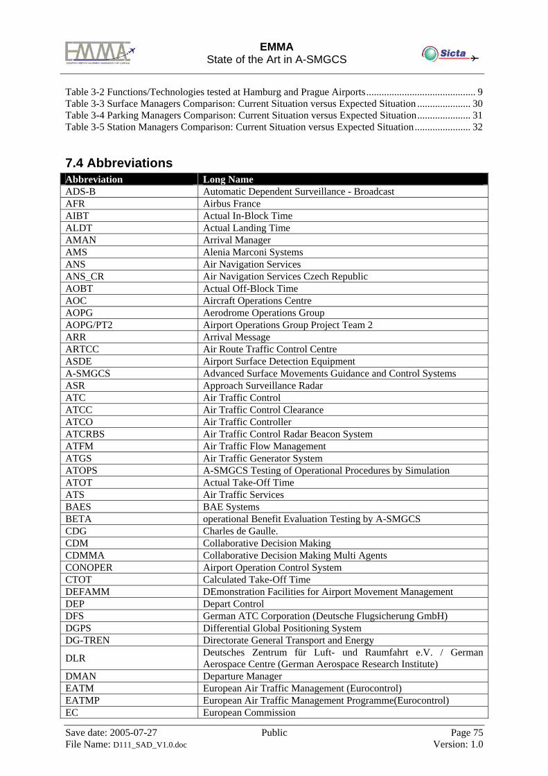
EMMA
State of the Art in A-SMGCS
Save date: 2005-07-27 Public Page 75 File Name: D111_SAD_V1.0.doc Version: 1.0
Table 3-2 Functions/Technologies tested at Hamburg and Prague Airports........................................... 9 Table 3-3 Surface Managers Comparison: Current Situation versus Expected Situation ..................... 30 Table 3-4 Parking Managers Comparison: Current Situation versus Expected Situation..................... 31 Table 3-5 Station Managers Comparison: Current Situation versus Expected Situation...................... 32
7.4 Abbreviations Abbreviation Long Name ADS-B Automatic Dependent Surveillance - Broadcast AFR Airbus France AIBT Actual In-Block Time ALDT Actual Landing Time AMAN Arrival Manager AMS Alenia Marconi Systems ANS Air Navigation Services ANS_CR Air Navigation Services Czech Republic AOBT Actual Off-Block Time AOC Aircraft Operations Centre AOPG Aerodrome Operations Group AOPG/PT2 Airport Operations Group Project Team 2 ARR Arrival Message ARTCC Air Route Traffic Control Centre ASDE Airport Surface Detection Equipment A-SMGCS Advanced Surface Movements Guidance and Control Systems ASR Approach Surveillance Radar ATC Air Traffic Control ATCC Air Traffic Control Clearance ATCO Air Traffic Controller ATCRBS Air Traffic Control Radar Beacon System ATFM Air Traffic Flow Management ATGS Air Traffic Generator System ATOPS A-SMGCS Testing of Operational Procedures by Simulation ATOT Actual Take-Off Time ATS Air Traffic Services BAES BAE Systems BETA operational Benefit Evaluation Testing by A-SMGCS CDG Charles de Gaulle. CDM Collaborative Decision Making CDMMA Collaborative Decision Making Multi Agents CONOPER Airport Operation Control System CTOT Calculated Take-Off Time DEFAMM DEmonstration Facilities for Airport Movement Management DEP Depart Control DFS German ATC Corporation (Deutsche Flugsicherung GmbH) DGPS Differential Global Positioning System DG-TREN Directorate General Transport and Energy
DLR Deutsches Zentrum für Luft- und Raumfahrt e.V. / German Aerospace Centre (German Aerospace Research Institute)
DMAN Departure Manager EATM European Air Traffic Management (Eurocontrol) EATMP European Air Traffic Management Programme(Eurocontrol) EC European Commission
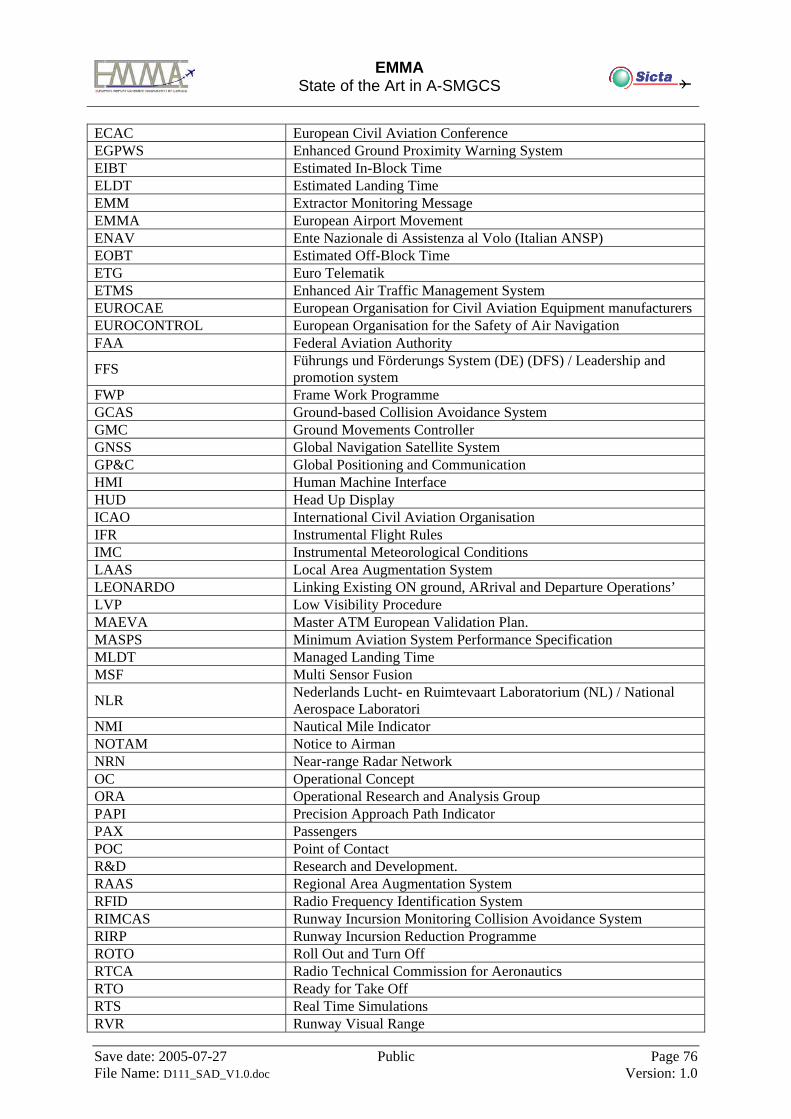
EMMA
State of the Art in A-SMGCS
Save date: 2005-07-27 Public Page 76 File Name: D111_SAD_V1.0.doc Version: 1.0
ECAC European Civil Aviation Conference EGPWS Enhanced Ground Proximity Warning System EIBT Estimated In-Block Time ELDT Estimated Landing Time EMM Extractor Monitoring Message EMMA European Airport Movement ENAV Ente Nazionale di Assistenza al Volo (Italian ANSP) EOBT Estimated Off-Block Time ETG Euro Telematik ETMS Enhanced Air Traffic Management System EUROCAE European Organisation for Civil Aviation Equipment manufacturers EUROCONTROL European Organisation for the Safety of Air Navigation FAA Federal Aviation Authority
FFS Führungs und Förderungs System (DE) (DFS) / Leadership and promotion system
FWP Frame Work Programme GCAS Ground-based Collision Avoidance System GMC Ground Movements Controller GNSS Global Navigation Satellite System GP&C Global Positioning and Communication HMI Human Machine Interface HUD Head Up Display ICAO International Civil Aviation Organisation IFR Instrumental Flight Rules IMC Instrumental Meteorological Conditions LAAS Local Area Augmentation System LEONARDO Linking Existing ON ground, ARrival and Departure Operations’ LVP Low Visibility Procedure MAEVA Master ATM European Validation Plan. MASPS Minimum Aviation System Performance Specification MLDT Managed Landing Time MSF Multi Sensor Fusion
NLR Nederlands Lucht- en Ruimtevaart Laboratorium (NL) / National Aerospace Laboratori
NMI Nautical Mile Indicator NOTAM Notice to Airman NRN Near-range Radar Network OC Operational Concept ORA Operational Research and Analysis Group PAPI Precision Approach Path Indicator PAX Passengers POC Point of Contact R&D Research and Development. RAAS Regional Area Augmentation System RFID Radio Frequency Identification System RIMCAS Runway Incursion Monitoring Collision Avoidance System RIRP Runway Incursion Reduction Programme ROTO Roll Out and Turn Off RTCA Radio Technical Commission for Aeronautics RTO Ready for Take Off RTS Real Time Simulations RVR Runway Visual Range
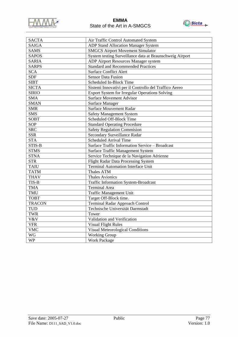
EMMA
State of the Art in A-SMGCS
Save date: 2005-07-27 Public Page 77 File Name: D111_SAD_V1.0.doc Version: 1.0
SACTA Air Traffic Control Automated System SAIGA ADP Stand Allocation Manager System SAMS SMGCS Airport Movement Simulator SAPOS System testing Surveillance data at Braunschweig Airport SARIA ADP Airport Resources Manager system SARPS Standard and Recommended Practices SCA Surface Conflict Alert SDF Sensor Data Fusion SIBT Scheduled In-Block Time SICTA Sistemi Innovativi per il Controllo del Traffico Aereo SIRIO Export System for Irregular Operations Solving SMA Surface Movement Advisor SMAN Surface Manager SMR Surface Mouvement Radar SMS Safety Management System SOBT Scheduled Off-Block Time SOP Standard Operating Procedure SRC Safety Regulation Commision SSR Secondary Surveillance Radar STA Scheduled Arrival Time STIS-B Surface Traffic Information Service – Broadcast STMS Surface Traffic Management System STNA Service Technique de la Navigation Aérienne STR Flight Radar Data Processing System TAIU Terminal Automation Interface Unit TATM Thales ATM THAV Thales Avionics TIS-B Traffic Information System-Broadcast TMA Terminal Area TMU Traffic Management Unit TOBT Target Off-Block time. TRACON Terminal Radar Approach Control TUD Technische Universität Darmstadt TWR Tower V&V Validation and Verification VFR Visual Flight Rules VMC Visual Meteorological Conditions WG Working Group WP Work Package