Embed Size (px)
Citation preview

BEGIN
FLOW MEASUREMENT
The gentle art of flow control depends on effective flow measurements responsive final
elements and the right control algorithms
As in so many other areas flow control continues to benefit from faster cheaper data
processing and communications but it is also leveraging better technologies and lower
costs in areas from corrosion-resistant alloys and piezoelectric sensors to low-stiction
valve seals and high-torque electric actuators Lower costs allow everyday use of tech-
nology once reserved only for the most demanding applications
This anthology of recent coverage in Control magazine and on ControlGlobalcom high-
lights recent developments and includes examples of outstanding implementations in
the process industries A deep dive into principles and prior coverage can be found in the
previous version of this work at httpinfocontrolglobalcomsot-151109-lp
ndash Editorial team
IMPROVED TECHNOLOGY IS IN OUR HANDS
STATE OF TECHNOLOGY
22
Table of ContentsDigital signals support low-maintenance approach 4 to differential pressure measurement
Why and how to establish installed 7 valve flow characteristics
Flow technologies team up to offer users 10 better measurements
What is the difference between uncertainty 15 and accuracy in flowmeters
Experts weigh in on distillation plant measurement 17 problems
Should you use a Coriolis flowmeter 19 as a backup system
Advertiser IndexBadger 16Emerson - Fisher 6Endress+Hauser 14FCI 3Krohne 5
33
The most versatile thermal mass gas flow meterhellip now and in the future
Calibrations for more than 200 different gases 4 - 20 mA HARTreg Foundation trade Fieldbus
PRoFibus Modbus Temperature service to 850 degF [454 degC] Pipe sizes from 1Prime to 99Prime [25 mm to 2500 mm]
1001 up to 10001 turndown 4-function flow rate total flow
temperature and pressure best-in-class digital graphical display Global agency approvals for Ex locations
44
A differential pressure (DP) application had cap-illariesmdashsmall-bore armored tubing connecting the remote seal to the transmittermdashin excess of
50 feet When the weather turned cold there was enough of a viscosity change in the fill fluid to cause a time lag in the longer leg making an otherwise quiescent measure-ment extremely noisy If this had been ldquorealrdquo DP instabil-ity it could have meant death and destruction for the mil-lions of dollars of precious metal catalyst in the reactor so it caused more than a little trepidationmdashuntil we figured out the correlation with cold weather
Twenty years ago a lot of end users became enamored with remote seals as an alternative to wet-leg DP level and DP flow applications Using DP for level has its appeal one gains some commonality or uniformity of spare parts with flow and pressure applications calibration standards and procedures are similar and service is uncomplicated compared with external-cage methods But wet legs are a challenge when the fluid filling the impulse lines (the tubing connecting the DP transmitter to the level taps) is prone to freezing polymerization or plugging of other kinds And since the DP measurement is in effect ldquoweigh-ingrdquo the head of the liquid above each tap undetected changes in density or specific gravity will cause an offset
or error in the level measurement as will gradual vapor-ization of fill fluid in the wet leg
Remote-seal DP transmitters for level address a number of the pitfalls of conventional wet-leg applications Only the vessel nozzle and the isolation valve to which the seal connects are vulnerable to freezing and plugging and they benefit from the conducted heat of the process it-self The fluid in the wet legs is purged free of any vapor pockets 100 filled with a synthetic oil and sealed with high-integrity welds This isolation also makes them ap-pealing for high-pressure corrosive or toxic applications where we prefer that the instrument tech isnrsquot exposed to the hazards But since such systems are sealed they im-pede everyday DP transmitter calibration and spare parts procedures
Frequently a dedicated spare is needed for each appli-cation Even though these properties caused the price to be double a normal DP level transmitter we specified quite a few of them
When the measurement is differential pressure whether direct (DP) or indirect (level) why not just use two pres-sure transmitters and take the difference The problem is the difference we aim to measure is often a minute fraction of the systemrsquos static pressure In the case of our reactor the
Digital signals support low-maintenance approach to differential pressure measurementDigital precision and stability allow accurate DP level and flow readings using two pressure transmitters
By John Rezabek process control specialist ISP Corp
55
static pressure is nearly 5000 psi and the DP of interest had a full scale of around 100 psi If you happen to find a transmitter with an upper range value (URV) of 5000 psig the full scale of the DP measurement is 2 of span A change of one or two pounds was meaningful which translates to 002 of span As Profibus expert and author James Powell pointed out in a November 2015 posting on the ldquoProfinewsrdquo website the uncertainty of 4-20 mA analog is degraded even further when the configured span is a fraction of the transmitterrsquos capability
We thought we might have to heat trace the capillaries For-tunately we had digitally integrated (fieldbus) transmitters
Today the reactor DP and a dozen other DP and level measurements have been converted from DP transmit-ters to ldquoDP by differencerdquo using two static pressure trans-mitters It works because the transmitters communicate digitally and carry a tighter spec and warranty for ac-curacy and stability right out of the box It costs moremdashyoursquore buying two transmitters instead of onemdashbut the method has become the standard whenever precision and reliability is critical If yoursquore measuring several DPs across a tower or reactor you only need N+1 transmitters (for example three to measure two DPs) so the cost dif-ference is less
If yoursquore using a legacy platform you can get the approx-imate performance by using any of the much-lauded ldquoelec-tronic remote sealsrdquo offered by Emerson Process Manage-ment or similar products from Endress+Hauser and Vega Similar to our method the difference is computed digitally in the transmitter but sent to the system as 4-20 mA You wonrsquot find a Profibus or Foundation fieldbus version of these products because the precision required is already there
ldquoThe reactor DP and a dozen other
DP and level measurements have
been converted from DP transmit-
ters to lsquoDP by differencersquo using
two static pressure transmittersrdquo
OPTIMASS 6400 - Mass Flow Meter Handles Entrained Gas
bull High performance Coriolis meterbull Operating range -3920F to +7520F to 2900 PSIGbull Superior liquid and gas performance with innovative twin tube designbull Optimized flow divider for minimum pressure lossbull Optional insulation heating jacketbull New MFC 400 converter easily handles entrained gas to 100
- Technology driven by KROHNE
Email infokrohnecomTel 1-800-FLOWING
uskrohnecom
Go With The Flow
OPTIMASS 6400
66
The Emerson logo is a trademark and service mark of Emerson Electric Co copy2016 Fisher Controls International LLC D352205X012 MBB104
Emersonrsquos industry leading Fishertrade easy-etrade control valvemdashavailable in NPS 1 thru 36mdashprovides users with high performance and proven reliability The easy-e control valve continues to evolve bringing you innovative and reliable technology to help solve your toughest challenges All valve designs undergo rigorous lifecycle testing so you donrsquot have to worry about your unit going down unexpectedly Donrsquot trust your process to replicated valves Use the Fisher easy-e control valve to keep your operation running Day and night To learn more visit wwwFishercomReliable
YOU CAN DO THAT
My unit is down again PerfectThese cheap valves just donrsquot hold upI need reliable technology to keep running 247365mdashno surprises
77
Why and how to establish installed valve flow characteristicsA detailed understanding can pay off in greater process stability
lower valve wear and less waste of materials and energy
By Greg McMillan and Stan Weiner
Stan Irsquove been an instrument engineer all of my professional life and Greg spent the first eight years of his career in con-struction installing checking out and commissioning instrumentation (be-tween stints as the lead engineer in in-strumentation design in new plants)
Greg I moved on into engineering tech-nology doing modeling and control for the rest of my 33 year career as a user I always took a great interest and appreci-ation in getting the best measurements and control valves In fact my early spe-cialties of compressor furnace pressure and pH control the resolution and re-sponse times of the sensors and control valves were critical and could make or break the system
I was given the time and freedom to de-velop the knowledge needed and the en-couragement to publish as much as possible of what Irsquove learned Robert Armstrong who I met at a recent users group meeting had an even longer heritage in instru-mentation by virtue of his father and himself each hav-ing more than 30 years of experience in instrumentation system design I can only imagine the fun and benefit of being able to discuss your field experience with your Dad
Instrumentation is an exciting profession I fell into the profession by accident Itrsquos difficult to explain to oth-
ers as can be seen in the cartoon on the front cover of my and Stanrsquos first funny book How to Become an Instru-ment Engineermdashthe Making of a Prima Donna In the cartoon a partygoer like me with drink in hand asks ldquoJust what does an instrument engineer dordquo By the way please ask Susan Colwell ISA manager of publications to put this book back in print When ISA went to the dig-ital-only version sales dropped to zero
Stan We would recommend the career to anyone Very few until recently have moved out by choice once having entered the profession We just need to make sure itrsquos still a viable option by showing the significance and value of what we have to offer Robert had a good idea of the potential career in instrumentation from his Dad Here we tap into Robertrsquos
knowledge on how to improve the reliability and linearity of control valves One of my areas of expertise was valve design and selection so combined with Gregrsquos sensitivity to valve sensitivity we have a great basis for helping our readers get the most out of control valves We start out with getting a perspective of the effort invested
Greg I was impressed by Robertrsquos detailed analysis of how to identify and use the installed characteristic that
INSTRUMENTATION
How to Become an Instrument Engi-
neermdashthe Making of a Prima Donna
by Greg McMillan and Stan Weiner
88
included considerable knowledge about fluid flow and the piping system installation details as seen in Robertrsquos pre-sentation ldquoHow to Select the Right Control Valverdquo Rob-ert what was your starting point
Robert I used Bernoullirsquos Theorem and the Darcy for-mula as documented in the Crane Technical Paper No 410 ldquoFlow of Fluids through Valves Fittings and Piperdquo The paper is an excellent extensive resource with cor-relations formulas figures tables and examples The equations were set up in Mathcad because it has a power-ful solver and graphing capabilities displays all equations in conventional math notationmdashno hidden cells or for-mulasmdashand it can readily handle automatic conversions between US Customary and SI engineering units
The Mathcad equations and input data for flow resis-tance of the piping segments were based on the piping isometric For the segment with the control valve the flow resistance was also a function of the control valve flow coefficient (Cv) whose values as function of posi-tion were determined from the vendorrsquos control valve siz-ing catalog Sizing catalog tables rather than theoretical curves (eg equal percentage) must be used for the inher-ent flow characteristic curves because the deviation be-tween the theoretical curves and actual curves is signifi-cant The installed flow characteristic is derived from the inherent flow characteristic and the varying pressure drop available to the control valve as function of flow based on the system resistance and pump curve For the segment with an orifice plate the flow resistance was also a func-tion of beta ratio The pump curve also needed to be en-tered
The first application consisted of two pumps on a vessel with a recirculation line back to the vessel with a control valve and restriction orifice There was a flow measure-ment in the total feed to the users downstream Initially this flow measurement was used for a total flow controller that throttled the control valve in the recirculation line However operations didnrsquot realize that the total flow was already controlled by each feed having its own flow con-troller The total flow controller had to be put in manual
to stop the oscillations from the fighting loops The cav-itation in the recirculation control valve was also severe The recycle valve position needed to be intelligently posi-tioned to minimize cavitation and enable tight individual feed flow control
The Mathcad model provided a three-dimensional (3D) plot of valve pressure drop versus recycle line orifice beta ratio and control valve position The plane for criti-cal pressure drop was added A valve pressure drop above this critical plane would correspond to valve cavitation The 3D plot enabled visualization of the best beta ratio in terms of preventing cavitation and enabling a lower minimum valve position that will ensure there is enough forward flow based on the pump curve for the highest combination of feed flow requirements
Once the best beta ratio is selected I could compute the flow and the process gain (change in flow per change in valve signal) as a function of valve position The result-ing process gain showed that the equal-percentage type of inherent characteristic introduced excessive nonlinearity This was fundamentally the wrong choice of flow char-acteristic which would have been a problem if we were trying to do closed-loop control say for example pump discharge pressure control
For this application it was sufficient to use the abil-ity gained from Mathcad model to compute the recycle flow providing a look-up table to set the recycle valve posi-tion needed to ensure meeting the total feed flow require-ment The solution greatly prolonged the life of the con-trol valve significantly reducing maintenance costs and improving onstream time by greater reliability
Stan Wersquove known for a long time that control valve in-stalled characteristic is a curve rather than a straight line introducing a significant nonlinearity into the control loop
Greg The slope of the curve is the valve gain that when multiplied by the process gain and measurement gain be-comes the dimensionless open-loop gain seen by the con-troller where the PID gain is inversely proportional to the
99
open-loop gain The measurement gain is simply 100 divided by the measurement span in engineering units which is constant The process gain for a flow loop is 1 making the open-loop gain simply the valve gain (eg gpm ) multiplied by the measurement gain (eg gpm) Thus for flow loops the control valve is the total source of nonlinearity For evaluating the linearity of con-trol valve characteristics the Y axis of the installed flow characteristic is flow and the X axis is valve position resulting in a dimensionless valve gain ( flow stroke) that is often called a process gain EnTech developed a specification that the process gain (ie valve gain) should be within 05 and 20 (41 gain change) in the operating range of the control valve I have espoused this guideline in my books most notably Essentials of Modern Measure-ments and Final Elements in the Process Industry
Stan Split-range control valves add a complication that is often not addressed Robert what is an example of how you have improved split-range control
Robert I had a fuel gas application where the pressure controller was manipulating split-range fuel gas control valves where the valves had different capacities and flow characteristics
In this case the installed flow characteristic was pretty much the inherent flow characteristic because the pres-sure drop across the valves was relatively constant I was consequently able to use the Cv table from the valve siz-ing catalog to develop a polynomial that would provide a plot of valve flow versus position The slope that is the valve gain could also be computed Since the small valve
had less capacity and its flow characteristic flattened out above 70 there was a sharp discontinuity seen as a sharp drop in valve gain at the conventional split-range point of 50 PID output
Just looking at the combined flow characteristic a high output limit of 80 stroke for the small valve and a split-range point of 40 would be better Upon further anal-ysis of valve gains a high output limit of 70 stroke and split-range point of 30 offered better linearity enabling the valve gain to stay within the 05 to 20 ( flow stroke) guideline for the expected throttle range The im-proved linearity of the split-range control valves enabled a smooth startup and subsequent years of great satisfaction with the project
Stan Eliminating a potential problem can help you gain appreciation for all of the other things that were done right on a project Thus the benefits extend beyond the focus of the solution The reverse is more obvious where an unsolved problem can spoil the satisfaction and per-ception of the project despite all of the great things that were done
ldquoEliminating a potential problem can help you gain appreciation
for all of the other things that were done right on a project
Thus the benefits extend beyond the focus of the solutionrdquo
1010
Flow technologies team up to offer users better measurementsSeveral distinct flow control technologies are coordinating efforts to give users more complete and accurate measurements in challenging phases and flow conditions
By Jim Montague executive editor Control
Similar to the onrushing and shape-shifting liquids and gases they manage flow control technologies may appear static even though economic forces are
churning them and many innovations are precipitating be-low the surface One of the most notable recent trends in flow is that besides perfecting their individual technologies several established flow methods are combining efforts more closely to take up the slack for each other fill in gaps in each otherrsquos capabilities and present more comprehensive and ac-curate information even for phases and flows that were pre-viously too difficult to measure
ldquoWersquore in the narrower gas flow and airgas measurement segment but the forces driving flowmeter technologies continue to escalaterdquo says Randy Brown marketing man-ager Fluid Components International (FCI) ldquoIn our case US Environmental Protection Agency rules on pollution CO2 and greenhouse gases keep the bar up and require measurements that werenrsquot done before so wersquore improving accuracy and building in recording devices
ldquoAlso because regulations demand more pervasive sensing we developed in-situ calibration verification so users will know their flowmeter is within specification without having to pull it out and test it in a lab As a result FCIrsquos ST100 multivariable flowmeters have VeriCal which is the only wet in-situ calibra-tion verification for thermal dispersion flow measurement It uses a retractable process connection which pulls up from the sensor in the pipe into a ball valve areardquo
Multi-pronged fluid strategiesSimilarly mass balance is equally crucial for complex pro-cesses in reactors and distillation columns but achieving it
requires accurate and reliable flow measurement Unfortu-nately Carom in Onesti Romania reports the differential pres-sure (DP) flowmeters in its methyl tertiary butyl ether (MTBE) plant previously required frequent maintenance because pro-cess fluids sometimes polymerized inside the meter clogging impulse lines and leading to bad measurements (Figure 1)
Figure 1 Carom Onestirsquos MTBE plant implemented Micro Motion
Coriolis flowmeters from Emerson Process Management to achieve
required mass balance and reduce product loss by 150 metric tons
per month and installed Rosemount 8800D Vortex flowmeters to mea-
sure the flow of superheated steam from nine boilers and eliminate
steam loss Credit Emerson and Carom
CORIOLIS AND VORTEX COOPERATE
1111
Consequently Carom implemented Micro Motion Cori-olis flowmeters from Emerson Process Management which enabled the MTBE plant to achieve required mass balance reduce product loss by 150 metric tons per month increase overall plant efficiency by 2 and save euro700000 per year Also because Micro Motion flowmeters have no moving parts maintenance costs were reduced Carom adds that the Coriolis flowmeters worked so well it also installed them on its diesel truck-loading system cutting its loading time by more than half and saving more than 300 labor hours and euro90000 per year
Additionally Carom formerly used three orifice flowmeters on impulse lines to measure the flow of superheated steam from nine boilers to the plantrsquos production units but the lines had chronic leaks and required about 300 hours of maintenance per year They also lost up to two tonnes of steam per hour which meant more fuel was needed to meet production de-mands In this case Carom picked Emersonrsquos vortex flowmeters ldquoFollowing the installation of Rosemount 8800D Vortex flow-meters with integral temperature sensors for each line im-provements were immediately evidentrdquo says Marian Stancu chief energy engineer at Carom Onesti ldquoMaintenance require-ments were reduced to almost nothing and because steam loss was eliminated boiler efficiency improved by 3 saving more than euro200000 per year in fuel This meant our initial invest-ment was recovered in just 25 days of operationrdquo
To further simplify its flow technologies and provide mea-surement verification in fiscal applications Emerson is re-leasing on Oct 12 its newly combined two-in-one redun-dant designs for Daniel Gas ultrasonic flowmeters This new flow platform elevates Danielrsquos proven British Gas design by providing two ultrasonic meters and transmitters in a sin-gle body and permitting two completely independent mea-surements with the installation of just one flowmeter The 3415 (four-path plus one-path) and 3416 (four-path plus two-path) gas ultrasonic flowmeters combine a four-path fiscal meter with an added check meter while the 3417 (four-path plus four-path) meter provides two fiscal meters for full re-dundancy and equal accuracy in one meter body This two-in-one redundant design provides continuous online ver-ification of custody transfer measurement integrity device health and process conditions and improves fiscal metering confidence while ensuring regulatory compliance
ldquoThe packaging of direct path measurement and reflective path technology combined in one ultrasonic flowmeter body as is the case in the 3415 and 3416 meters helps avoid common mode errorrdquo says Lonna Dickenson Emersonrsquos marketing manager for ultrasonic meters ldquoThe primary fiscal flow mea-surement is performed by a four-path chordal meter while the verification of this primary measurement is achieved by a sin-gle reflective path meter The reflection technology sees even small amounts of liquid or contamination on the pipe wall that remain completely hidden in a direct path design This is par-ticularly important when metering rich dirty or wet gasrdquo
Dickenson adds that each measurement by 3415 3416 or 3417 has its own independent signal processing unit Should the fiscal meter ever fail the check meter will pro-vide a complete backup measurement ensuring availabil-ity and uptime In the past natural gas operators needed a second flowmeter for monitoring the first one while some didnrsquot even have a way to monitor the fiscal meter and had to make field trips to get a maintenance log Now monitor-ing is inclusive and verification is simplified detecting pro-cess upsets long before the measurement is impaired and reducing time and money spent on assets
Ultrasonics optimize biogasTo push into new applications and remote locations ultra-sonic flowmeters are adding paths and combining previously separate support functions
For instance the municipal wastewater facility in Read-ing Pa is using Proline Prosonic Flow B 200 ultrasonic flowmeters and support software from Endress+Hauser to monitor gas flows temperatures and methane fractions from its anaerobic digesters and biogas application which must be carefully managed to produce methane generate elec-tricity and reduce plant operating costs
Readingrsquos three 800000-gallon digesters can handle up to 285 million gallons per day but they need to maintain an op-timum 95 degF for their anaerobic bacteria to efficiently generate a wet biogas flow of 3500 standard cubic feet per hour with a 65-70 methane fraction This gas is drawn off to fuel three 70-horsepower boilers which provide the heat needed to keep the each digesterrsquos heat constant even in subzero weather
The plant can usually maintain a closed-loop to optimize
1212
digester bacteria but chief electrical engineer John Ger-berich reports this goal used to be elusive due an outdated pressure transducer monitoring biogas flow via its SCADA telemetry network manual temperature monitoring and time-wasting analysis of gas samples to determine methane fractions This lack of real-time data led to operational la-tency and high costs such as the methane fraction dropping below 20 and temperature falling to 80 degF
ldquoWhen these conditions occur a digester can sour causing the bacteria to produce higher levels of other gases that can accelerate corrosion of all our plumbingrsquos metal partsmdashpip-ing controls regulators and so onrdquo says Gerberich ldquoWhatrsquos more if the methane fraction falls too much we have to tap external natural gas to fuel the boilers and that can cost us up to $16000 a month I really wanted a way to measure tem-perature and methane fraction in real time so we could dis-pense with lab testing which took us so much timerdquo
Gerberich implemented B 200 ultrasonic flowmeters after learning they were designed for applications like real-time monitoring of wet dirty biogas with variable composition and low flow and pressure This gave the operators real-time measures of biogas flow temperature and methane fraction which enabled them to adjust the sludge they feed the di-gesters more precisely without waiting for test results
He estimates the labor savings in sampling and lab testing time at approximately $20000 per year and that tear-down maintenance on the boilers has been cut in half due to less corrosion and wear and tear saving another $15000 per year ldquoThe biggest savings however come from minimizing if not eliminating the need for external natural gas to fuel the boil-ersrdquo adds Gerberich ldquoBefore the plant would have to sup-plement its methane fuel in cold winter months at a cost av-eraging $37500 a year With total annual savings of $72500 a year B 200 paid for itself several times over in its first yearrdquo
Beyond incremental improvements Jerry Stevens senior product manager for the flow group at Endress+Hauser sees three main trends affecting all the flow measurement meth-ods ldquoThe focus is on how flow and other technologies can conform to relevant safety requirements improve their re-liability and functional safety remove hazardous detection faults and design safety instrumented systems (SISs) that still reduce maintenance and calibration frequencyrdquo says
Stevens ldquoThe second trend is quality of measurements that can be expected from flowmeters in adverse conditions and then designing to improve device quality and efficiency Us-ers need flow measurements and meters that up to the qual-ity of their overall engineering efforts but they also need devices that are more predictive and allow them to react to events with predefined remedies
ldquoFinally device availability is the third trend Users want platform-agnostic components so they can pick and choose whatrsquos best for their applications and not be forced into dras-tic upgrades They also want equipment that can interface with any field devices via remote Ethernet and wireless pro-tocols as well as HMIs with local and embedded-memory displays that allow auto-configuration and hot swappingrdquo
All along the pipelineFarther out in the field Honeywell Process Solutions (HPS) reports its ultrasonic flowmeters flow computers and temperature and pressure transmitters will help im-prove operations on Chinarsquos long-distance Guangxi lique-fied natural gas (LNG) high-pressure pipeline which is a strategic project of Sinopec Ltd and the Guangxi Zhuang
Figure 2 The 1300-mile high-pressure Guangxi LNG pipeline is using
ultrasonic flowmeters flow computers and temperature and pressure
transmitters from Honeywell Process Solutions improve operations
and move 8 billion cubic meters of LNG per year from Maoming to
Beihai in the Guangxi region Credit Honeywell and Sinopec
LONG PIPELINE RUNNING
1313
autonomous region (Figure 2) The pipeline is scheduled for completion later this year and will have a capacity of 8 billion cubic meters of LNG per year and a total length of more than 1300 miles from Maoming to Beihai in the Guangxi region The pipeline will be part of a network that transports natural gas and LNG to China from as far away as Kazakhstan
ldquoPipelines have challenges that are very different from processing plants because you have to manage an oper-ation that is hundreds or sometimes thousands of miles longrdquo says Aldous Wong vice president at HPS for greater China ldquoMeasurements such as flow and pressure must be accurate and immediately accessible to keep the pipeline operating efficientlyrdquo
Integrated gas technologies from HPS that will help maintain optimum performance on the long-distance Guangxi LNG include ultrasonic flowmeters to measure natural gas for custody transfer applications flow comput-ers to perform parallel calculations of compressibility ac-cording to established methods including GERG 88 S AGA 8 and AGA NX 19 and SmartLine temperature and pressure transmitters
Coriolis redoubles effortsThough Coriolis flowmeters arenrsquot the exotic novelties they were years ago theyrsquore still finding new frontiers and applications to conquer
To improve the accuracy of its new automatic mixing line for manufacturing shampoo products Unileverrsquos plant in Gebze Turkey recently adopted six Micro Motion Elite and F-Series Coriolis flowmeters from Emerson Process Management to measure mass flows of its silicone feed-stock which improved product quality and reduced pro-duction time by 10-15 (Figure 3)
Though blending accuracy is crucial to final product quality Unilever discovered that the linersquos original Cori-olis flowmeters couldnrsquot measure feedstock flow because of entrained gas in the silicone and found that an early fix using weigh scales and load cells took too long and wasted raw material and energy
Several other flowmeters were tested but they couldnrsquot
work in the mixerrsquos operating vacuum of -700 mbarg that helps remove the bubbles Next Unilever tested the Elite Coriolis flowmeters which have low-frequency flow sen-sors that increase flow accuracy in the presence of two-phase flow as well as multivariable digital (MVD) technol-ogy that improves accuracy and stability of Coriolis signals from the flow sensors This enhanced signal processing sensor stability and design ensures accurate measurements even under entrained gas conditions
ldquoOur tests found that the Micro Motion Elite Corio-lis flowmeters were the only meters that can successfully measure silicone feedstock flow with high density bub-blesrdquo says Atilla Bozkaya Unileverrsquos project control and system design engineer ldquoThe meters maintained measure-ment accuracy despite operating in the -700 mbarg vac-uum needed in this applicationrdquo
Unilever saved 17 on operating costs by eliminating the scales and load cells and added 12 more Elite and F-Series Coriolis flowmeters when the Gebze plant added two more mixers
Figure 3 Unileverrsquos silicone mixer at its plant in Gebze Turkey imple-
mented six Micro Motion Elite and F-Series Coriolis flowmeters to
measure mass flow of feedstock despite entrained bubbles improve
shampoo product quality and reduce production time 10-15
Credit Emerson and Unilever
SHAMPOO MASS FLOW
1414
Endress+Hauser Inc2350 Endress PlaceGreenwood IN 46143infousendresscom888-ENDRESSwwwusendresscom
Flowing with great possibilities
Proline Promass F 100 Coriolis FlowmeterUltra-compact without compromise
Anwendung in Magazinen
Anwendung inBroschuumlren
Anwendung insw-Publikationen
The Promass F 100 opens entirely new possibilities for system integrators skid builders and equipment manufactures providing full functionality flow measurement in a compact designbull Multi-variable device simultaneous measurement of mass or
volume flow corrected volume density and temperaturebull Seamless integration into process control and asset management
systems via HARTreg PROFIBUSreg DP EtherNetIPtrade or Modbus RS485bull Modern web server technology for fast onsite device configuration
without additional tools or softwarebull Industry optimized sensor with high accuracy even under
varying process conditionsbull Heartbeat Technologytrade - monitor your process via continuous
diagnostics multi-parameter monitoring and onboard verification for maximum process reliability
Discover the possibilities wwwusendresscompromass-f100
1515
What is the difference between uncertainty and accuracy in flowmetersBeacutela Liptaacutek says the there is no such thing as a perfect detector therefore we never know what ldquotrue valuerdquo is
This column is moderated by Beacutela Liptaacutek automation and safety consultant and editor of the Instrument and Automation Engineersrsquo Handbook (IAEH) If you have an automation-re-lated question for this column write to liptakbelaaolcom
QuestionWhat is the difference between uncertainty and accuracy in flowmeters Why do custody transfer ultrasonic flowmeter manufacturers state uncertainty value instead of accuracyA Rahimi arahimitamcoir
AnswerAccuracy (or more precisely ldquoinaccuracyrdquo or error) can be defined as the closeness of the result of a measurement to the true value of the measurand Unfortunately we never know what that ldquotrue valuerdquo is because there is no such thing as a perfect detector Uncertainty should reflect this by using the term uncertainty as the sum of the inaccuracies of the instrument and of the reference Unfortunately some vendors play ldquospecmanshiprdquo with these terms and the worst ones donrsquot even state the basis of their numbersmdashthey donrsquot state if the percentage they give is based on the full scale (FS) or the actual reading (AR) of the measurement
As far as the performance of ultrasonic flowmeters it de-pends on the nature of the process fluid (medium) and on the meterrsquos ldquolinkagerdquo The medium is the acoustically con-ductive process fluid through which the sound is traveling Linkage is based on the integrity of the bond between ad-jacent mediums (transducer and pipe wall pipe wall and lining if present lining and process fluid etc) From this it can be seen that wetted transducer installations will exhibit superior results than ldquoclamp-onrdquo ones
Now if we disregard the reference error measurement uncertainty is composed of two types of error precision er-ror and systematic error The precision or random error is a function of the quality of vendorrsquos hardware which hope-fully was determined in the carefully controlled environ-ment of a flow lab This is the error usually listed in the manufacturerrsquos specifications It is however impossible to replicate the carefully controlled conditions of the flow lab in the field This introduces the second type of error the systematic error This second error component encompasses all factors that are related to the meterrsquos actual installation Some of these include the pipersquos outside surface the pipersquos inside surface the bonding of the liner if liners are used coating or buildup in the pipe pipe eccentricity roundness or ovality pipe material environmental factors and flow pro-file (Reynolds number) to name some of the more common ones This systematic error can add up to 5 FS to the total uncertainty of the measurement
So how good are ultrasonic flow meters That depends on three design features
bull Wetted or clamp-onbull Time of flight (TOF) or Dopplerbull Rangeability requiredThe accuracy of a wetted TOF unit is about 1 FS The
reading accuracy at the actual flow is very much a function of the ratio between maximum and minimum flow to be detected (rangeability) Remember at minimum flow the Reynolds number must still exceed 10000 So at 50 flow the accuracy of the above meter is 2 AR (actual reading) and at 20 flow it is 5 AR If Doppler designs are used the error can double and when clamp-on units are used it can double again
1616
Measure What Matters
Badger Meter helps you measure what matters today protecting precious resources for tomorrowrsquos generation You can depend on our industry-leading flow measurement solutions to help you optimize your
operations leading to a better bottom line and a better world Measure to manage manage to sustain
Minimize Waste Maximize Efficiency Leave a Better Footprint
Measure What MattersMeasure What Matters
wwwbadgermetercom
INC-AD-02086-EN-01 (May 2016)
1717
Experts weigh in on distillation plant measurement problemsBela Liptak and his crew tell how to resolve difficulties with measuring column differential pressure and flows of flare and natural gas
This column is moderated by Beacutela Liptaacutek automation and safety consultant and editor of the Instrument and Automation Engineersrsquo Handbook (IAEH) If you have an automation-re-lated question for this column write to liptakbelaaolcom
QuestionI always use your valuable books in my field as a control amp instrumentation engineer I have three questions and if you could help me it will be so appreciated
1 Installation differential pressure transmitters on tall towers (inlet and outlet) for vapor service has been a big problem for me I have mounted a differential pressure (DP) transmitter above the outlet line of the tower with its low-pressure side connected by a sloping tube to the out-let pipe and high-pressure side connected to the tower in-let pipe with a 14-meter-long tube We have two pressure gauges on the inlet and outlet pipes showing 3 PSID while the DP cell reads 600 mbar (9 PSID) What is the problem condensation What is the remedy increasing slope or in-sulation A similar case has not been resolved and I had to use two pressure transmitters (PT) to get software differen-tial value When I touch the low tapping its temperature is colder than the other leg Butene is the measured vapor
2 In another process we have a flare flow measured by a pitot tube The flowrate is between zero and 24500 kgh We need a rangability of 201 which cannot be measured by the DP-type sensor because it shows 0 kgh at all times Should we select and substitute a thermal mass or ultrasonic flow-meter We want to see from the lowest possible flowrate (zero if possible) to 24500 kgh Inlet pressure is less than 05 bar fluid temperature -20250 C What is your suggestion
3 I want to select and size a flowmeter for natural gas ser-vice with maximum 6000 kgh flowrate in 4-in pipe that has
one PT and temperature transmitter (TT) This flowmeter is for custody transfer of natural gas at 6 bar pressure and nor-mal flowrate of 1500 kgh operating at ambient temperature
I need your kind help and your unparalleled informationmdash Rahim Rome rahim1356gmailcom
AnswersOn question 1 the left side of Figure 1 shows my under-standing of what you have now and on the right I am show-ing what I would do to fix your problem In general I do not like to use conventional DP cells to measure the pressure difference between points that are at different elevations be-cause the lead lines can introduce errors due to condensa-tion or due to errors caused by differences in temperature or density on the two sides of the cell These problems can be reduced by using capillaries or pressure repeaters but why bother The best solution in my experience is to use two
ΔPT
P12
P11
P1-P2 = 200 mb
ΔPT= 600 mb
ΔP
PT1
PT2
You have Replace with
Figure 1 Tower pressure drop measurement
TWO GOOD PRESSURE TRANSMITTERS
1818
good pressure transmitters and measure the difference be-tween their outputs as shown on the right of Figure 1
On question 2 you are right pitot tubes can not be used for rangeabilities above 31 I assume that you do not need to mea-sure the flare flow very accurately so a wet and cooled time of signal passage-type multipath and intelligent ultrasonic flow-meter with compensation for composition pressure and tem-perature (density) variations would be an option If you want direct mass flow measurement use a thermal (lower cost and accuracy) or Coriolis meter (higher cost and accuracy)
On question 3 for high-accuracy mass flow measurement when the composition and density of the gas varies use a Coriolis flowmetermdash Beacutela Liptaacutek liptakbelaaolcom
Flowmeter engineering is intertwined with deep under-standing of process process behavior operational ranges process thermodynamics and flow system engineering as to what is the objective for example custody transfer process control or flow indication as the questions indicate Instru-mentation engineering is applied science requiring more knowledge than just transmitters and orifice plates
On question 1 your transmitter leg on the high side is very long compared to the low side and because of this the ef-fect of the fluid thermal expansioncontraction in the impulse line has a potential of giving you this error As you know the coefficient of thermal expansion varies by the cube of the expansion coefficient Insulation of the impulse tubes may helpmdashmy suggestion would be to use capillary filled tubes of equal length on both sides low and high side Make sure the capillary lengths of both legs are the same and are exposed to the same ambient condition One leg should not be in shade and the other in sun because we want to negate the ther-mal effects The capillary should eliminate the effect of phase changes etc so it would give a more accurate measurement
On question 2 here using a Pitot tube is wrong because of its limitations on rangability or flow turndown In most flare header lines because of the EPA regulations an ul-trasonic meter is used however you have to compensate it with composition analyzer pressure and temperature to get accurate measurement of flare gases You mention a tem-perature range of -20 to 250 C The high temperature is not suitable for ultrasonic sensors On the low side you may
want to contact Flexim which supplies cryogenic ultrasonic flowmeters and may be able to add cooling extension plates between the sensor and pipe to make it also suitable for your high temperature Multiple thermal mass flowmeters for varying temperature conditions may be another option but accuracy would suffer I am not sure what can handle the high side of your temperature range
On question 3 variation in composition and range from (pilot flow to max flow) is a daunting task for any flowmeter Most people settle for ultrasonic flow however for results to be meaningful you would need a composition measure-ment which could be expensive Orifice is a wrong for this application if you need high accuracy and wide turndown (orificce plate is 31) Your best bet is an ultrasonic flwometer with pressure and temperature compensationmdash Romel S Bhullar senior technical director Fluor Corp
romelbhullarfluorcom
On question 1 since the low pressure side of the dp cell is con-nected to the pressure tap at the top of the column it is recom-mended that the cell itself be located above that point so that this low side will be self draining back into the top outlet pipe With this configuration the high pressure side of the dp cell will have a very lead line connecting it to the pressure tap at the bottom of the column inlet pipe Depending on the thermal insulation used on the lead lines and on the temperatures of the process streams at the in and outlets of the column there might be condensation in these tubes which might introduce some errors Yet this configuration is still better than locating the dp cell down at the level of the inlet pipe because then the lead line to the low side will not be self draining but can fill and if it does that side will become the high pressure side In any case you may need to recalibrate the transmitter
On question 2 the biggest issue here is that generally flare gases have a mixture of products so the density variations as well as moisture content can affect the measurement I would recommend a Coriolis meter in case you want precise measurements (see Micro Motion ELITE Coriolis Flow and Density Meters) A Pitot tube will not give you better than 31 rangeability and even than density compensation will be needed That can be obtained by periodic lab testingmdash Alex (Alejandro) Varga project amp construction management
Devco vargaalexyahoocom
1919
Should you use a Coriolis flowmeter as a backup systemA backup system may not be the best use of a Coriolis meter and a century-old gas meter technology that still has some life in it
This column is moderated by Beacutela Liptaacutek automation and safety consultant and editor of the Instrument and Automation Engineersrsquo Handbook (IAEH) If you have an automation-re-lated question for this column write to liptakbelaaolcom
Question I am working at RCSPL a design and detailed engineer-ing company for the oil amp gas sector in India The condi-tions of my application are these Service ndashfuel gas line Pipeline size ndash 2 in Flow rate ndash 1000 lbhr
Presently an orifice meter (concentric square edge) measures the fuel gas flow The client wants a Coriolis flowmeter in series with and upstream of the orifice plate to provide it with backup Are there any problems that we should consider concerning this installation If not please advise how the installation of this Coriolis flowme-ter should be made mdash R Muthuganesan
muthuganesanrgmailcom
AnswersThe Coriolis flowmeter is superior to the orifice-type sensor because it di-rectly measures the mass flow has low maintenance requires practically no straight pipe runs and provides both better accuracy and better rangeabil-ity than does the orifice-based flow-meter The orifice is a volumetric flow detector and therefore requires pres-sure temperature and density com-pensation to determine the mass flow requires more maintenance longer
straight pipe runs and both its accuracy and rangeability are lower For these reasons I would not use the Coriolis meter as a backup but would use it as the primary sensor
As to installation I would prefer to install the Corio-lis meter downstream of the orifice because the Corio-lis has practically no upstream straight pipe run require-ment while that of the orifice is substantial particularly if an upstream restriction is present such as a smaller-than-pipe-size Coriolis meter In your case in the 2-in pipe the Coriolis will probably be 1 or 15 in Its preferred installa-tion would be in a vertical pipe with upward flow direction (Figure 1) This should be in a location where there is no vibration and the pipe does not transmit much compres-sion tension or shear force onto the meter
Finally I should note that while this addition will pro-vide a backup still when the two meters disagree you
will not know which reading is the right one although the probability is that it will be the Coriolis You should provide block and bypass valves so when one meter is removed for any rea-son you can continue operation using the othermdash Beacutela Liptaacutek liptakbelaaolcom
Based on my experience both types of flowmeters are suited for the described application There is nothing special in the installation requirements of the Co-riolis instrument The supplier of the in-strument will give you any requirementsrecommendations if such existmdash Avihu Hiram AvihuHiramEngcom
The Coriolis flowmeter is more accurate
and reliable than an orifice therefore it
should be the primary sensor and not a
backup for the orifice Credit Endress+Hauser
FIRST CHOICE
2020
In general you will have difficulty reconciling the measure-ments between the Coriolis (basically a mass flow device) and the orifice plate The conversion from mass to volumet-ric flow on a fuel gas line (gas has low density) will not be accurate due to the density measurement not being accurate for lower densities
This is also a problematic configuration because there will be discrepancies between the two readings and the user will have to continually justify them Also this does not account for any inaccuracies in the orifice reading
I am not sure that the client understands ldquobackuprdquo since the measurements will disagree and the client will not know which is to be taken as the good one
You have not really given enough information about the process We need to know
bull Gas pressure temperature and densitybull Allowable pressure drop (you now have additional in-
strumentation in the line)bull Piping configuration (eg is there a pressure regula-
tor in the gas line)bull Whether this is feeding a fuel gas header or an indi-
vidual piece of equipment (eg fired heater) andbull Reliability requirements
There are straight-run requirements for an orifice plate (more for upstream) It would be better to place the Co-riolis downstream of the orifice because it will introduce significant flow profile disturbance for the orifice You will need at least a 40-pipe-diameter straight pipe run from the Coriolis if installed upstream of the orifice plate (You could probably get away with five to 10 diameters if the Coriolis is downstream)
You can go to the vendor websites and find the siz-ing procedure for the Coriolis meters There you will find data on size required pressure drop etc However this would not be the sort of installation I would do I would choose one flowmeter or the other but not bothmdash Simon Lucchini SimonLucchinifluorcom
Technically there is no problem in putting them in series provided straight pipe length requirements are adhered to If you do not have sufficient length I suggest you can remove the orifice plate and preserve it for use when the Coriolis meter is not working With this you may be able to satisfy the required straight lengths
However since the Coriolis meter is more accurate and failures are very few if possible you can consider stop-ping use of the orifice plate permanentlymdash H S Gambhir HarvindarSGambhirrilcom
The only issue that you need to take into account is the up-stream straight pipe distance required for the Coriolis meter and the orifice From this perspective one can view the Co-riolis meter as a valve or restriction to the flow By making this assumption you can use Table 3 of ISO 51672 to de-termine the straight pipe requirement of the orifice meter if the Coriolis is upstream of it Depending on the beta ratio the upstream pipe lengths will be between 12 and 24 pipe diameters
If the beta ratio is between 05 and 065 the pipe diam-eter requirements are between 12 and 18 Therefore in a 2-in line the Coriolis meter should be more than 24 in upstream of the orifice plate and not more than 36 in If there are more bends and changes of direction then the required pipe lengths need to be adjusted accordinglyAlejandro Varga vargaalexyahoocom
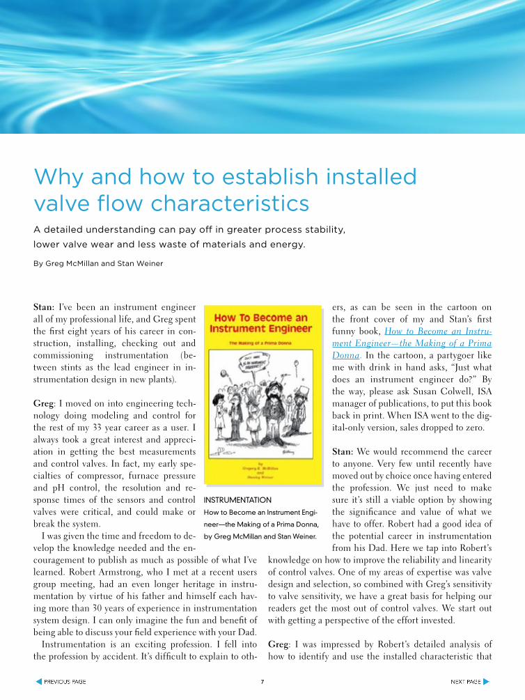
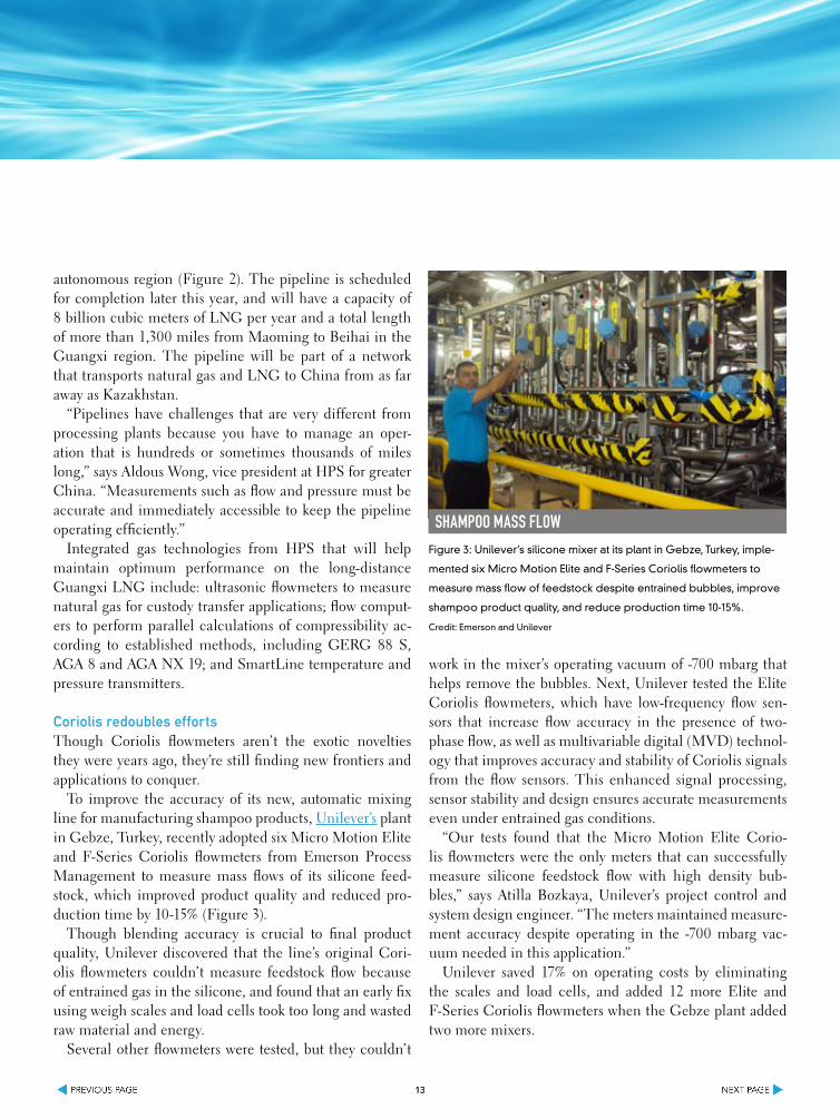


![2741666 Flow Measurement Technology[1]](https://img.pdfslide.us/doc/110x75/577d349c1a28ab3a6b8e70eb/2741666-flow-measurement-technology1.jpg)