Embed Size (px)
Citation preview

STATE OF DELAWAREDEPARTMENT OF TRANSPORTATION
JACK MARKELL PO BOX 778 JENNIFER COHAN GOVERNOR DOVER, DELAWARE 19903 SECRETARY
VIA WEBSITE POSTING (302) 760-2030FAX (302) 739-2254
July 15, 2016
Contract No. T201680102.01Magnolia Truck WashKent County
Ladies and Gentlemen:
Enclosed is Addendum No. 2 for the referenced contract consisting of the following:
1. The date for the receipt of bids has been moved to Tuesday, July 26, 2016, at 2:00 p.m.
2. The Bid Proposal Cover, revised, to be substituted for the same page in the Proposal.
3. One (1) page, Special Provision 763569-Buildings, page 42, revised, to be substituted for the samepage in the Proposal. There is no mandatory Pre-Bid Meeting requirement for this project.
4. The following sections have been added to Appendix A-Technical Specifications:
087100 - Door Hardware099600 - High Performance Coatings220524 - Check Valves For Plumbing Piping220553 - Identification For Plumbing Piping and Equipment220719 - Plumbing Piping Insulation221116 - Domestic Water Piping221119 - Domestic Water Piping Specialties221316 - Sanitary Waste and Vent Piping221323 - Sanitary Waste Interceptors222114 - Facility Natural Gas Piping230000 - Basic Mechanical Materials and Methods230529 - Hangers and Supports
5. One (1) page, Plan Sheet 18, revised, to be substituted for the same page in the Proposal.
Please note the revision listed above and submit your bid based upon this information.
Sincerely,
~signature on file~
Robert A. Kovacs
Competitively Bid Contracts Coordinator

STATE OF DELAWARE
DEPARTMENT OF TRANSPORTATION
BID PROPOSAL
for
CONTRACT T201680102.01
MAGNOLIA TRUCK WASH
KENT COUNTY
ADVERTISEMENT DATE: June 13, 2016
PROSPECTIVE BIDDERS ARE ADVISED THAT THERE WILL BE A PRE-BID MEETING WEDNESDAYJUNE 29, 2016 AT 10:00 A.M. IN THE DelDOT ADMINISTRATION BUILDING,
800 BAY ROAD, DOVER, DELAWARE, 19903.
COMPLETION TIME: 150 210 Calendar Days
SPECIFICATIONS FOR ROAD AND BRIDGE CONSTRUCTIONDELAWARE DEPARTMENT OF TRANSPORTATION
AUGUST 2001
Bids will be received in the Bidder's Room at the Delaware Department of Transportation's Administration Building, 800 Bay Road, Dover, Delaware until 2:00 P.M. local time July 19 July 26, 2016
Addendum No. 2July 15, 2016

Contract No. T201680102.01
763569 - BUILDINGS
Description:
This work consists of all equipment, labor, materials necessary to furnish and install the maintenanceshop building complete per the contract drawings. The work specifically includes but is not necessarilylimited to the building shell including foundation and footers. It also includes the concrete floor, walls,plumbing, electrical, HVAC, mechanical, lighting, and all other items indicated within the building asindicated in the Contract Drawings and noted in the technical specifications in Appendix A.
Materials and Construction:
All materials and construction shall conform to the requirements of the Contract Drawings and anytechnical specifications referenced.
Mandatory Pre-Bid Meeting:
All bidders must be represented at the Mandatory Pre-Bid Meeting(s) for this contract. The meetinginformation is provided on the first page of this contract (page i). The bidder’s representative must sign-inand identify the name of the bidder they represent.
Failure to sign-in with the bidder’s company name at the Mandatory Pre-Bid Meeting will result inthe bidder being found non-responsible and non-responsive, and their bid will be rejected.
Method of Measurement:
Payment for this item will be made on a lump sum basis wherein no measurement will be made.
Basis of Pavment:
Payment will be made at the Lump Sum price bid for this item. The price bid shall include the costfor performing the work specified and furnishing all labor, materials, tools, equipment and incidentalsnecessary to provide a complete, working and usable facility acceptable to the Engineer.
5/23/16
42
Addendum No. 2 July 15, 2016

SECTION 087100
DOOR HARDWARE
PART 1 - GENERAL
1.1 RELATED SECTIONS
A. General Provisions, Terms and Conditions, Special Provisions, other Division 1 Specifications
Sections and Drawings apply to this Section.
1.2 SUMMARY
A. Section includes:
1. Mechanical door hardware for the following:
a. Swinging doors.
B. Related Sections:
1. Section 081119 “Stainless Steel Doors and Frames”.
2. Section 083323 "Overhead Coiling Doors" for door hardware provided as part of
overhead coiling door assemblies.
1.3 ACTION SUBMITTALS
A. Product Data: For each type of product indicated. Include construction and installation details,
material descriptions, dimensions of individual components and profiles, and finishes.
B. Door Hardware Schedule: Prepared by or under the supervision of Installer's Architectural
Hardware Consultant. Coordinate door hardware schedule with doors, frames, and related work
to ensure proper size, thickness, hand, function, and finish of door hardware.
1. Format: Use same scheduling sequence and format and use same door numbers as in door
hardware schedule in the Contract Documents.
2. Content: Include the following information:
a. Identification number, location, hand, fire rating, size, and material of each door
and frame.
b. Locations of each door hardware set, cross-referenced to Drawings on floor plans
and to door and frame schedule.
c. Complete designations, including name and manufacturer, type, style, function,
size, quantity, function, and finish of each door hardware product.
d. Fastenings and other installation information.
e. Explanation of abbreviations, symbols, and designations contained in door
hardware schedule.
Addendum No. 2 July 15, 2016
f. Mounting locations for door hardware.
C. Other Action Submittals:
1. Keying Schedule: Prepared by or under the supervision of Installer, detailing Owner's
final keying instructions for locks. Include schematic keying diagram and index each key
set to unique door designations that are coordinated with the Contract Documents.
1.4 INFORMATIONAL SUBMITTALS
A. Warranty: Special warranty specified in this Section.
1.5 QUALITY ASSURANCE
A. Perform work in accordance with the following requirements:
1. ANSI/ICC A117.1 American National Standards for Accessible and Usable Buildings
and Facilities.
2. Applicable provisions of NFPA 101 Life Safety Codes.
B. Hardware Supplier Qualifications: Company specializing in supplying commercial door
hardware with a minimum of ten (10) years of documented experience. The hardware supplier
shall have warehousing facilities with-in 100 miles of the project and employ a certified
Architectural Hardware Consultant.
1.6 DELIVERY, STORAGE, AND HANDLING
A. Inventory door hardware on receipt and provide secure lock-up for door hardware delivered to
Project site.
B. Tag each item or package separately with identification coordinated with the final door
hardware schedule, and include installation instructions, templates, and necessary fasteners with
each item or package.
C. Deliver keys to manufacturer of key control system for subsequent delivery to Owner.
1.7 COORDINATION
A. Installation Templates: Distribute for doors, frames, and other work specified to be factory
prepared. Check Shop Drawings of other work to confirm that adequate provisions are made for
locating and installing door hardware to comply with indicated requirements.
B. Security: Coordinate installation of door hardware, keying, and access control with Owner's
security consultant.
C. Existing Openings: Where hardware components are scheduled for application to existing
construction or where modifications to existing door hardware are required, field verify existing
Addendum No. 2 July 15, 2016

conditions and coordinate installation of door hardware to suit opening conditions and to
provide proper door operation.
1.8 WARRANTY
A. Special Warranty: Manufacturer's standard form in which manufacturer agrees to repair or
replace components of door hardware that fail in materials or workmanship within specified
warranty period.
1. Failures include, but are not limited to, the following:
a. Structural failures including excessive deflection, cracking, or breakage.
b. Faulty operation of doors and door hardware.
c. Deterioration of metals, metal finishes, and other materials beyond normal
weathering and use.
2. Warranty Period: Three years from date of Substantial Completion, unless otherwise
indicated.
a. Manual Closers: 10 years from date of Substantial Completion.
1.9 MAINTENANCE SERVICE
A. Maintenance Tools and Instructions: Furnish a complete set of specialized tools and
maintenance instructions for Owner's continued adjustment, maintenance, and removal and
replacement of door hardware.
PART 2 - PRODUCTS
2.1 PERFORMANCE REQUIREMENTS
A. Means of Egress Doors: Latches do not require more than 15 lbf to release the latch. Locks do
not require use of a key, tool, or special knowledge for operation.
B. Accessibility Requirements: For door hardware on doors in an accessible route, comply with the
DOJ's "2010 ADA Standards for Accessible Design”.
1. Provide operating devices that do not require tight grasping, pinching, or twisting of the
wrist and that operate with a force of not more than 5 lbf .
2. Bevel raised thresholds with a slope of not more than 1:2. Provide thresholds not more
than 1/2 inch high.
3. Adjust door closer sweep periods so that, from an open position of 90 degrees, the door
will take at least 5 seconds to move to a position of 12 degrees from the latch.
4. Adjust spring hinges so that, from an open position of 70 degrees, the door will take at
least 1.5 seconds to move to the closed position.
Addendum No. 2 July 15, 2016
2.2 SCHEDULED DOOR HARDWARE
A. Provide door hardware for each door as scheduled in Part 3 "Door Hardware Schedule" Article
and on Drawings to comply with requirements in this Section.
1. Door Hardware Sets: Provide quantity, item, size, finish or color indicated, and products
equivalent in function and comparable in quality to named products.
B. Designations: Requirements for design, grade, function, finish, size, and other distinctive
qualities of each type of door hardware are indicated in Part 3 "Door Hardware Schedule"
Article. Products are identified by using door hardware designations, as follows:
1. Named Manufacturers' Products: Manufacturer and product designation are listed for
each door hardware type required for the purpose of establishing minimum requirements.
Manufacturers' names are abbreviated in Part 3 "Door Hardware Schedule" Article.
2.3 HINGES
A. Hinges: BHMA A156.1. Provide template-produced hinges for hinges installed on hollow metal
doors and hollow-metal frames.
1. Manufacturers: Subject to compliance with requirements, provide products by one of the
following:
a. Bommer Industries, Inc.
b. Lawrence Hardware Inc.
c. McKinney Products Company; an ASSA ABLOY Group company.
2.4 MECHANICAL LOCKS AND LATCHES
A. Lock Functions: As indicated in door hardware schedule.
B. Lock Throw: Comply with testing requirements for length of bolts required for labeled fire
doors, and as follows:
1. Bored Locks: Minimum 1/2-inch latchbolt throw.
2. Mortise Locks: Minimum 3/4-inch latchbolt throw.
3. Deadbolts: Minimum 1-inch bolt throw.
C. Lock Backset: 2-3/4 inches, unless otherwise indicated.
D. Strikes: Provide manufacturer's standard strike for each lock bolt or latchbolt complying with
requirements indicated for applicable lock or latch and with strike box and curved lip extended
to protect frame; finished to match lock or latch.
E. Mortise Locks: BHMA A156.13; Grade 1; stamped steel case with steel or brass parts;
Series 1000.
1. Manufacturers: Subject to compliance with requirements, provide products by one of the
following:
Addendum No. 2 July 15, 2016
a. Adams Rite Manufacturing Co.; an ASSA ABLOY Group company.
b. Arrow USA; an ASSA ABLOY Group company.
c. Corbin Russwin Architectural Hardware; an ASSA ABLOY Group company.
d. SARGENT Manufacturing Company; an ASSA ABLOY Group company.
e. Yale Security Inc.; an ASSA ABLOY Group company.
2.5 LOCK CYLINDERS
A. Lock Cylinders: Tumbler type, constructed from brass or bronze, stainless steel, or nickel silver.
1. Manufacturer: Match existing building standard.
B. Standard Lock Cylinders: BHMA A156.5; Grade 1; permanent cores that are interchangeable;
face finished to match lockset.
2.6 KEYING
A. Keying System: Factory registered, complying with guidelines in BHMA A156.28,
Appendix A. Incorporate decisions made in keying conference.
1. Existing System:
a. Master key or grand master key locks to Owner's system.
B. Keys: to match owners existing.
2.7 SURFACE CLOSERS
A. Surface Closers: BHMA A156.4; rack-and-pinion hydraulic type with adjustable sweep and
latch speeds controlled by key-operated valves and forged-steel main arm. Comply with
manufacturer's written instructions for size of door closers depending on size of door, exposure
to weather, and anticipated frequency of use. Provide factory-sized closers, adjustable to meet
field conditions and requirements for opening force.
1. Manufacturers: Subject to compliance with requirements, provide products by one of the
following:
a. Corbin Russwin Architectural Hardware; an ASSA ABLOY Group company.
b. LCN Closers; an Ingersoll-Rand company.
c. SARGENT Manufacturing Company; an ASSA ABLOY Group company.
d. Yale Security Inc.; an ASSA ABLOY Group company.
2.8 DOOR GASKETING
A. Door Gasketing: BHMA A156.22; air leakage not to exceed 0.30 cfm per foot of crack length
for gasketing other than for smoke control, as tested according to ASTM E 283; with resilient or
flexible seal strips that are easily replaceable and readily available from stocks maintained by
manufacturer.
Addendum No. 2 July 15, 2016

1. Manufacturers: Subject to compliance with requirements, provide products by one of the
following:
a. Pemko Manufacturing Co.; an ASSA ABLOY Group company.
b. Reese Enterprises, Inc.
c. Zero International.
2.9 THRESHOLDS
A. Thresholds: BHMA A156.21; fabricated to full width of opening indicated.
1. Manufacturers: Subject to compliance with requirements, provide products by one of the
following:
a. Pemko Manufacturing Co.; an ASSA ABLOY Group company.
b. Reese Enterprises, Inc.
c. Zero International.
2.10 FABRICATION
A. Manufacturer's Nameplate: Do not provide products that have manufacturer's name or trade
name displayed in a visible location except in conjunction with required fire-rated labels and as
otherwise approved by Architect.
1. Manufacturer's identification is permitted on rim of lock cylinders only.
B. Base Metals: Produce door hardware units of base metal indicated, fabricated by forming
method indicated, using manufacturer's standard metal alloy, composition, temper, and
hardness. Furnish metals of a quality equal to or greater than that of specified door hardware
units and BHMA A156.18.
C. Fasteners: Provide door hardware manufactured to comply with published templates prepared
for machine, wood, and sheet metal screws. Provide screws that comply with commercially
recognized industry standards for application intended, except aluminum fasteners are not
permitted. Provide Phillips flat-head screws with finished heads to match surface of door
hardware, unless otherwise indicated.
1. Concealed Fasteners: For door hardware units that are exposed when door is closed,
except for units already specified with concealed fasteners. Do not use through bolts for
installation where bolt head or nut on opposite face is exposed unless it is the only means
of securely attaching the door hardware. Where through bolts are used on hollow door
and frame construction, provide sleeves for each through bolt.
2. Spacers or Sex Bolts: For through bolting of hollow-metal doors.
3. Gasketing Fasteners: Provide noncorrosive fasteners for exterior applications and
elsewhere as indicated.
2.11 FINISHES
A. Provide finishes complying with BHMA A156.18 as indicated in door hardware schedule.
Addendum No. 2 July 15, 2016
B. Protect mechanical finishes on exposed surfaces from damage by applying a strippable,
temporary protective covering before shipping.
C. Appearance of Finished Work: Variations in appearance of abutting or adjacent pieces are
acceptable if they are within one-half of the range of approved Samples. Noticeable variations
in the same piece are not acceptable. Variations in appearance of other components are
acceptable if they are within the range of approved Samples and are assembled or installed to
minimize contrast.
PART 3 - EXECUTION
3.1 EXAMINATION
A. Examine doors and frames, with Installer present, for compliance with requirements for
installation tolerances, labeled fire-rated door assembly construction, wall and floor
construction, and other conditions affecting performance.
B. Proceed with installation only after unsatisfactory conditions have been corrected.
3.2 INSTALLATION
A. Mounting Heights: Mount door hardware units at heights to comply with the following unless
otherwise indicated or required to comply with governing regulations.
1. Standard Steel Doors and Frames: ANSI/SDI A250.8.
B. Install each door hardware item to comply with manufacturer's written instructions. Where
cutting and fitting are required to install door hardware onto or into surfaces that are later to be
painted or finished in another way, coordinate removal, storage, and reinstallation of surface
protective trim units with finishing. Do not install surface-mounted items until finishes have
been completed on substrates involved.
1. Set units level, plumb, and true to line and location. Adjust and reinforce attachment
substrates as necessary for proper installation and operation.
2. Drill and countersink units that are not factory prepared for anchorage fasteners. Space
fasteners and anchors according to industry standards.
C. Hinges: Install types and in quantities indicated in door hardware schedule but not fewer than
the number recommended by manufacturer for application indicated or one hinge for every 30
inches of door height, whichever is more stringent, unless other equivalent means of support for
door, such as spring hinges or pivots, are provided.
D. Lock Cylinders: Install construction cores to secure building and areas during construction
period.
1. Replace construction cores with permanent cores directed by Owner.
2. Furnish permanent cores to Owner for installation.
E. Thresholds: Set thresholds for exterior doors and other doors indicated in full bed of sealant.
Addendum No. 2 July 15, 2016
F. Stops: Provide floor stops for doors unless wall or other type stops are indicated in door
hardware schedule. Do not mount floor stops where they will impede traffic.
G. Perimeter Gasketing: Apply to head and jamb, forming seal between door and frame.
H. Meeting Stile Gasketing: Fasten to meeting stiles, forming seal when doors are closed.
I. Door Bottoms: Apply to bottom of door, forming seal with threshold when door is closed.
3.3 ADJUSTING
A. Initial Adjustment: Adjust and check each operating item of door hardware and each door to
ensure proper operation or function of every unit. Replace units that cannot be adjusted to
operate as intended. Adjust door control devices to compensate for final operation of heating
and ventilating equipment and to comply with referenced accessibility requirements.
1. Door Closers: Adjust sweep period to comply with accessibility requirements and
requirements of authorities having jurisdiction.
3.4 CLEANING AND PROTECTION
A. Clean adjacent surfaces soiled by door hardware installation.
B. Clean operating items as necessary to restore proper function and finish.
C. Provide final protection and maintain conditions that ensure that door hardware is without
damage or deterioration at time of Substantial Completion.
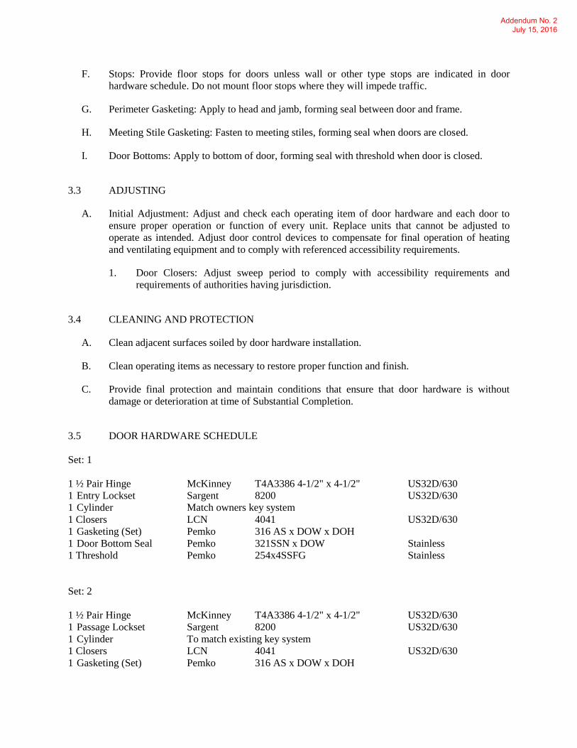
3.5 DOOR HARDWARE SCHEDULE
Set: 1
1 ½ Pair Hinge McKinney T4A3386 4-1/2" x 4-1/2" US32D/630
1 Entry Lockset Sargent 8200 US32D/630
1 Cylinder Match owners key system
1 Closers LCN 4041 US32D/630
1 Gasketing (Set) Pemko 316 AS x DOW x DOH
1 Door Bottom Seal Pemko 321SSN x DOW Stainless
1 Threshold Pemko 254x4SSFG Stainless
Set: 2
1 ½ Pair Hinge McKinney T4A3386 4-1/2" x 4-1/2" US32D/630
1 Passage Lockset Sargent 8200 US32D/630
1 Cylinder To match existing key system
1 Closers LCN 4041 US32D/630
1 Gasketing (Set) Pemko 316 AS x DOW x DOH
Addendum No. 2 July 15, 2016

1 Door Bottom Seal Pemko 321SSN x DOW Stainless
Set: 3
1 ½ Pair Hinge McKinney T4A3386 4-1/2" x 4-1/2" US26D/626
1 Entry Lockset Sargent 8200 US26D/626
1 Cylinder To match existing key system
1 Closers LCN 4041 US26D/626
1 Gasketing (Set) Pemko 316 AS x DOW x DOH
1 Door Bottom Seal Pemko 345 AV x DOW Aluminum, Mill
1 Threshold Pemko 1715 Aluminum, Mill
END OF SECTION 087100
Addendum No. 2 July 15, 2016

099600-1
SECTION 099600
HIGH-PERFORMANCE COATINGS
PART 1 - GENERAL
1.1 RELATED DOCUMENTS
A. Drawings and general provisions of the Contract, including General and Supplementary
Conditions and Division 01 Specification Sections, apply to this Section.
1.2 SUMMARY
A. Section includes surface preparation and the application of high-performance coating
systems on the following substrates:
1. Interior Substrates:
a. Concrete, horizontal surfaces.
b. Concrete masonry units (CMUs). c. Steel.
B. Related Requirements:
1. Section 099123 "Interior Painting" for general field painting.
1.3 DEFINITIONS
A. MPI Gloss Level 5: 35 to 70 units at 60 degrees, according to ASTM D 523.
B. MPI Gloss Level 6: 70 to 85 units at 60 degrees, according to ASTM D 523.
C. MPI Gloss Level 7: More than 85 units at 60 degrees, according to ASTM D 523.
1.4 ACTION SUBMITTALS
A. Product Data: For each type of product. Include preparation requirements and
application instructions.
1. Include printout of current "MPI Approved Products List" for each product
category specified, with the proposed product highlighted.
2. Indicate VOC content.
B. Samples for Initial Selection: For each type of topcoat product indicated.
C. Samples for Verification: For each type of coating system and each color and gloss of
topcoat indicated.
Addendum No. 2 July 15, 2016
099600-2
1. Submit Samples on rigid backing, 8 inches square.
2. Apply coats on Samples in steps to show each coat required for system. 3. Label each coat of each Sample.
4. Label each Sample for location and application area.
D. Product List: Cross-reference to coating system and locations of application areas. Use
same designations indicated on Drawings and in schedules. Include color designations.
1.5 MAINTENANCE MATERIAL SUBMITTALS
A. Furnish extra materials, from the same product run, that match products installed and that
are packaged with protective covering for storage and identified with labels describing contents.
1. Coatings: 5 percent, but not less than 1 gal. of each material and color applied.
1.6 QUALITY ASSURANCE
A. Mockups: Apply mockups of each coating system indicated to verify preliminary
selections made under Sample submittals and to demonstrate aesthetic effects and set
quality standards for materials and execution.
1. Architect will select one surface to represent surfaces and conditions for application of each coating system.
a. Wall and Ceiling Surfaces: Provide samples of at least 100 sq. ft.
b. Other Items: Architect will designate items or areas required.
2. Final approval of color selections will be based on mockups.
a. If preliminary color selections are not approved, apply additional
mockups of additional colors selected by Architect at no added cost to Owner.
3. Approval of mockups does not constitute approval of deviations from the
Contract Documents contained in mockups unless Architect specifically approves
such deviations in writing. 4. Subject to compliance with requirements, approved mockups may become part of
the completed Work if undisturbed at time of Substantial Completion.
1.7 DELIVERY, STORAGE, AND HANDLING
A. Store materials not in use in tightly covered containers in well-ventilated areas with
ambient temperatures continuously maintained at not less than 45 deg F.
1. Maintain containers in clean condition, free of foreign materials and residue.
2. Remove rags and waste from storage areas daily.
Addendum No. 2 July 15, 2016
099600-3
1.8 FIELD CONDITIONS
A. Apply coatings only when temperature of surfaces to be coated and ambient air temperatures are between 50 and 95 deg F.
B. Do not apply coatings when relative humidity exceeds 85 percent; at temperatures less
than 5 deg F above the dew point; or to damp or wet surfaces.
C. Do not apply exterior coatings in snow, rain, fog, or mist.
PART 2 - PRODUCTS
2.1 MANUFACTURERS
A. Products: Subject to compliance with requirements, provide one of the products listed in the Exterior High-Performance Coating Schedule or Interior High-Performance Coating
Schedule for the coating category indicated.
2.2 HIGH-PERFORMANCE COATINGS, GENERAL
A. MPI Standards: Products shall comply with MPI standards indicated and shall be listed
in its "MPI Approved Products Lists."
B. Material Compatibility:
1. Materials for use within each paint system shall be compatible with one another and substrates indicated, under conditions of service and application as
demonstrated by manufacturer, based on testing and field experience.
2. For each coat in a paint system, products shall be recommended in writing by topcoat manufacturers for use in paint system and on substrate indicated.
3. Products shall be of same manufacturer for each coat in a coating system.
C. Colors: As selected by Architect from manufacturer's full range.
2.3 SOURCE QUALITY CONTROL
A. Testing of Coating Materials: Owner reserves the right to invoke the following
procedure:
1. Owner will engage the services of a qualified testing agency to sample coating materials. Contractor will be notified in advance and may be present when
samples are taken. If coating materials have already been delivered to Project
site, samples may be taken at Project site. Samples will be identified, sealed, and certified by testing agency.
2. Testing agency will perform tests for compliance with product requirements.
3. Owner may direct Contractor to stop applying coatings if test results show
materials being used do not comply with product requirements. Contractor shall remove noncomplying coating materials from Project site, pay for testing, and
Addendum No. 2 July 15, 2016
099600-4
recoat surfaces coated with rejected materials. Contractor will be required to
remove rejected materials from previously coated surfaces if, on recoating with complying materials, the two coatings are incompatible.
PART 3 - EXECUTION
3.1 EXAMINATION
A. Examine substrates and conditions, with Applicator present, for compliance with requirements for maximum moisture content and other conditions affecting performance
of the Work.
B. Maximum Moisture Content of Substrates: When measured with an electronic moisture meter as follows:
1. Concrete: 12 percent.
2. Masonry (Clay and CMUs): 12 percent.
C. Verify suitability of substrates, including surface conditions and compatibility, with
existing finishes and primers.
D. Proceed with coating application only after unsatisfactory conditions have been
corrected.
1. Application of coating indicates acceptance of surfaces and conditions.
3.2 PREPARATION
A. Comply with manufacturer's written instructions and recommendations in "MPI Architectural Painting Specification Manual" applicable to substrates and coating systems
indicated.
B. Remove hardware, covers, plates, and similar items already in place that are removable and are not to be painted. If removal is impractical or impossible because of size or
weight of item, provide surface-applied protection before surface preparation and
painting.
1. After completing painting operations, use workers skilled in the trades involved to reinstall items that were removed. Remove surface-applied protection if any.
C. Clean substrates of substances that could impair bond of coatings, including dust, dirt,
oil, grease, and incompatible paints and encapsulants.
1. Remove incompatible primers and reprime substrate with compatible primers or
apply tie coat as required to produce coating systems indicated.
Addendum No. 2 July 15, 2016

099600-5
D. Concrete Substrates: Remove release agents, curing compounds, efflorescence, and
chalk. Do not coat surfaces if moisture content or alkalinity of surfaces to be coated exceeds that permitted in manufacturer's written instructions.
1. Clean surfaces with pressurized water. Use pressure range of 1500 to 4000 psi at
6 to 12 inches.
2. Abrasive blast clean surfaces to comply with SSPC-SP 7/NACE No. 4.
E. Masonry Substrates: Remove efflorescence and chalk. Do not coat surfaces if moisture
content, alkalinity of surfaces, or alkalinity of mortar joints exceeds that permitted in
manufacturer's written instructions.
F. Shop-Primed Steel Substrates: Clean field welds, bolted connections, and areas where
shop paint is abraded. Paint exposed areas with the same material as used for shop
priming to comply with SSPC-PA 1 for touching up shop-primed surfaces.
3.3 APPLICATION
A. Apply high-performance coatings according to manufacturer's written instructions and
recommendations in "MPI Architectural Painting Specification Manual."
1. Use applicators and techniques suited for coating and substrate indicated. 2. Coat surfaces behind movable equipment and furniture same as similar exposed
surfaces. Before final installation, coat surfaces behind permanently fixed
equipment or furniture with prime coat only. 3. Coat backsides of access panels, removable or hinged covers, and similar hinged
items to match exposed surfaces.
4. Do not apply coatings over labels of independent testing agencies or equipment name, identification, performance rating, or nomenclature plates.
B. Tint each undercoat a lighter shade to facilitate identification of each coat if multiple
coats of the same material are to be applied. Tint undercoats to match color of finish
coat, but provide sufficient difference in shade of undercoats to distinguish each separate coat.
C. If undercoats or other conditions show through final coat, apply additional coats until
cured film has a uniform coating finish, color, and appearance.
D. Apply coatings to produce surface films without cloudiness, spotting, holidays, laps,
brush marks, runs, sags, ropiness, or other surface imperfections. Produce sharp glass
lines and color breaks.
3.4 FIELD QUALITY CONTROL
A. Dry Film Thickness Testing: Owner may engage the services of a qualified testing and
inspecting agency to inspect and test coatings for dry film thickness.
1. Contractor shall touch up and restore coated surfaces damaged by testing.
Addendum No. 2 July 15, 2016
099600-6
2. If test results show that dry film thickness of applied coating does not comply
with coating manufacturer's written recommendations, Contractor shall pay for testing and apply additional coats as needed to provide dry film thickness that
complies with coating manufacturer's written recommendations.
3.5 CLEANING AND PROTECTION
A. At end of each workday, remove rubbish, empty cans, rags, and other discarded materials from Project site.
B. After completing coating application, clean spattered surfaces. Remove spattered
coatings by washing, scraping, or other methods. Do not scratch or damage adjacent finished surfaces.
C. Protect work of other trades against damage from coating operation. Correct damage to
work of other trades by cleaning, repairing, replacing, and recoating, as approved by Architect, and leave in an undamaged condition.
D. At completion of construction activities of other trades, touch up and restore damaged or
defaced coated surfaces.
3.6 INTERIOR HIGH-PERFORMANCE COATING SCHEDULE
A. Concrete Substrates, Horizontal Surfaces.
1. Epoxy, High-Build System:
a. Prime Coat: High-build epoxy, matching topcoat (reduced). b. Intermediate Coat: High-build epoxy, matching topcoat.
c. Topcoat: High-build epoxy, low gloss, MPI #108.
1) Sherwin Williams; Macropoxy 646 Fast Cure Epoxy. 2) PPG Architectural; High Build Epoxy Marine Coating.
3) Approved Equal.
B. CMU Substrates:
1. Epoxy, High-Build System:
a. Prime Coat: Epoxy block filler, MPI #116.
b. Intermediate Coat: High-build epoxy, matching topcoat.
c. Topcoat: High-build epoxy, low gloss, MPI #108.
1) Sherwin Williams; Macropoxy 646 Fast Cure Epoxy.
2) PPG Architectural; High Build Epoxy Marine Coating.
3) Approved Equal.
Addendum No. 2 July 15, 2016

099600-7
C. Steel Substrates:
1. Epoxy, High-Build System:
a. Prime Coat: Primer, epoxy, anti-corrosive, for metal, MPI #101.
b. Intermediate Coat: High-build epoxy, matching topcoat.
c. Topcoat: High-build epoxy, low gloss, MPI #108.
1) Sherwin Williams; Macropoxy 646 Fast Cure Epoxy. 2) PPG Architectural; High Build Epoxy Marine Coating.
3) Approved Equal.
PART 4 - METHOD OF MEASUREMENT
4.1 METHOD OF MEASUREMENT:
A. No separate measurement shall be made for work under this section.
PART 5 - BASIS OF PAYMENT
5.1 METHOD OF PAYMENT:
A. No separate payment will be made for work under this Specification Section. The cost of
the work, complete in place, described in this Specification Section shall be included in
the respective Lump Sum Bid.
B. Costs include all labor, material, services and equipment necessary to complete the work
in every respect
END OF SECTION 099600
Addendum No. 2 July 15, 2016

099600-8
THIS PAGE INTENTIONALLY LEFT BLANK
Addendum No. 2 July 15, 2016
220524-1
SECTION 220524
CHECK VALVES FOR PLUMBING PIPING
PART 1 - GENERAL
1.1 RELATED DOCUMENTS
A. Drawings and general provisions of the Contract, including General and Supplementary
Conditions and Division 01 Specification Sections, apply to this Section.
1.2 SUMMARY
A. Section Includes:
1. Bronze swing check valves.
2. Stainless Steel Check Valves
1.3 DEFINITIONS
A. CWP: Cold working pressure.
B. EPDM: Ethylene propylene-diene terpolymer rubber.
C. NBR: Acrylonitrile-butadiene, Buna-N, or nitrile rubber.
1.4 ACTION SUBMITTALS
A. Product Data: For each type of valve.
1. Certification that products comply with NSF 61 and NSF 372.
1.5 DELIVERY, STORAGE, AND HANDLING
A. Prepare valves for shipping as follows:
1. Protect internal parts against rust and corrosion.
2. Protect threads, flange faces, grooves, and weld ends.
3. Set check valves in either closed or open position.
B. Use the following precautions during storage:
1. Maintain valve end protection.
2. Store valves indoors and maintain at higher-than-ambient-dew-point temperature.
If outdoor storage is necessary, store valves off the ground in watertight
enclosures.
Addendum No. 2 July 15, 2016
220524-2
C. Use sling to handle large valves; rig sling to avoid damage to exposed parts. Do not use
handwheels or stems as lifting or rigging points.
PART 2 - PRODUCTS
2.1 GENERAL REQUIREMENTS FOR VALVES
A. Source Limitations for Valves: Obtain each type of valve from single source from single
manufacturer.
B. Where check valves are connected to stainless steel piping, the check valves shall be of
like stainless steel.
C. ASME Compliance:
1. ASME B1.20.1 for threads for threaded end valves.
2. ASME B16.10 and ASME B16.34 for ferrous valve dimensions and design
criteria.
3. ASME B16.18 for solder joint.
4. ASME B31.9 for building services piping valves.
D. AWWA Compliance: Comply with AWWA C606 for grooved-end connections.
E. NSF Compliance: NSF 61 and NSF 372 for valve materials for potable-water service.
F. Bronze valves shall be made with dezincification-resistant materials. Bronze valves
made with copper alloy (brass) containing more than 15 percent zinc are not permitted.
G. Valve Pressure-Temperature Ratings: Not less than indicated and as required for system
pressures and temperatures.
H. Valve Sizes: Same as upstream piping unless otherwise indicated.
I. Valve Bypass and Drain Connections: MSS SP-45.
2.2 BRONZE (STAINLESS STEEL) SWING CHECK VALVES
A. Class 125, Bronze, Swing Check Valves with Bronze Disc:
1. Manufacturers: Subject to compliance with requirements, provide products by the
following:
a. Crane Co.; Crane Valve Group; Stockham Valves.
b. Milwaukee Valve Company.
c. NIBCO INC.
d. Watts Regulator Co.; a division of Watts Water Technologies, Inc.
Addendum No. 2 July 15, 2016

220524-3
2. Description:
a. Standard: MSS SP-80, Type 3.
b. CWP Rating: working pressure of the installed system, 200 psig
minimum.
c. Body Design: Horizontal flow.
d. Body Material: ASTM B 62, bronze.
e. Ends: Threaded or soldered. See valve schedule articles.
f. Disc: Bronze.
3. Per 2.1 B. above, where check valves are connected to stainless steel piping, the
check valves shall be made of like stainless steel.
PART 3 - EXECUTION
3.1 EXAMINATION
A. Examine valve interior for cleanliness, freedom from foreign matter, and corrosion.
Remove special packing materials, such as blocks, used to prevent disc movement during
shipping and handling.
B. Operate valves in positions from fully open to fully closed. Examine guides and seats
made accessible by such operations.
C. Examine threads on valve and mating pipe for form and cleanliness.
D. Examine mating flange faces for conditions that might cause leakage. Check bolting for
proper size, length, and material. Verify that gasket is of proper size, that its material
composition is suitable for service, and that it is free from defects and damage.
E. Do not attempt to repair defective valves; replace with new valves.
3.2 VALVE INSTALLATION
A. Install valves with unions or flanges at each piece of equipment arranged to allow
service, maintenance, and equipment removal without system shutdown.
B. Locate valves for easy access and provide separate support where necessary.
C. Install valves in horizontal piping with stem at or above center of pipe.
D. Install valves in position to allow full stem movement.
E. Install check valves for proper direction of flow and as follows:
1. Swing Check Valves: In horizontal position with hinge pin level.
Addendum No. 2 July 15, 2016

220524-4
F. Install valve tags. Comply with requirements in Section 220553 "Identification for
Plumbing Piping and Equipment" for valve tags and schedules.
3.3 ADJUSTING
A. Adjust or replace valve packing after piping systems have been tested and put into service
but before final adjusting and balancing. Replace valves if persistent leaking occurs.
3.4 GENERAL REQUIREMENTS FOR VALVE APPLICATIONS
A. If valve applications are not indicated, use the following:
1. Pump-Discharge Check Valves:
a. NPS 2 and Smaller: Bronze swing check valves with [bronze] disc.
B. If valves with specified CWP ratings are unavailable, the same types of valves with
higher CWP ratings may be substituted.
C. End Connections:
1. For Copper Tubing, NPS 2 and Smaller: Threaded or soldered.
2. For Copper Tubing, NPS 2-1/2 to NPS 4: Flanged or threaded.
3.5 DOMESTIC HOT- AND COLD-WATER VALVE SCHEDULE
A. Pipe NPS 4 and Smaller: Bronze swing check valves, Class 125, bronze disc with
soldered or threaded end connections.
1. Per 2.1 B. above, where check valves are connected to stainless steel piping, the
check valves shall be made of like stainless steel.
END OF SECTION 220524
Addendum No. 2 July 15, 2016
220553-1
SECTION 220553
IDENTIFICATION FOR PLUMBING PIPING AND EQUIPMENT
PART 1 - GENERAL
1.1 SUMMARY
A. Section Includes:
1. Equipment labels.
2. Warning signs and labels.
3. Pipe labels.
4. Valve Tags
1.2 ACTION SUBMITTALS
A. Product Data: For each type of product indicated.
PART 2 - PRODUCTS
2.1 EQUIPMENT LABELS
A. Metal Labels for Equipment and valve tags:
1. Material and Thickness: Brass, 0.032-inch minimum thickness, and having
predrilled or stamped holes for attachment hardware. Use Stainless Steel labels
and tags in the Wash Bay.
2. Letter Color: ANSI standard.
3. Background Color: ANSI standard
4. Minimum Label Size: Length and width vary for required label content, but not
less than 2-1/2 by 3/4 inch.
5. Minimum Letter Size: 1/4 inch for name of units if viewing distance is less than
24 inches, 1/2 inch for viewing distances up to 72 inches, and proportionately
larger lettering for greater viewing distances. Include secondary lettering two-
thirds to three-quarters the size of principal lettering.
6. Fasteners: Stainless-steel rivets or stainless steel self-tapping screws. Valve tags
may be attached with brass chain; use Stainless Steel Chain in the Wash Bay.
7. Adhesive: Contact-type permanent adhesive, compatible with label and with
substrate.
B. Plastic Labels for Equipment:
1. Material and Thickness: Multilayer, multicolor, plastic labels for mechanical
engraving, 1/16 inch thick, and having predrilled holes for attachment hardware.
2. Letter Color: ANSI standard
Addendum No. 2 July 15, 2016

220553-2
3. Background Color: ANSI Standard
4. Maximum Temperature: Able to withstand temperatures up to 160 deg. F.
5. Minimum Label Size: Length and width vary for required label content, but not
less than 2-1/2 by 3/4 inch.
6. Minimum Letter Size: 1/4 inch for name of units if viewing distance is less than
24 inches, 1/2 inch for viewing distances up to 72 inches and proportionately
larger lettering for greater viewing distances. Include secondary lettering two-
thirds to three-quarters the size of principal lettering.
7. Fasteners: Stainless-steel rivets or self-tapping screws.
8. Adhesive: Contact-type permanent adhesive, compatible with label and with
substrate.
C. Label Content: Include equipment's Drawing designation or unique equipment number,
Drawing numbers where equipment is indicated (plans, details, and schedules), and the
Specification Section number and title where equipment is specified.
D. Equipment Label Schedule: For each item of equipment to be labeled, on 8-1/2-by-11-
inch bond paper. Tabulate equipment identification number, and identify Drawing
numbers where equipment is indicated (plans, details, and schedules) and the
Specification Section number and title where equipment is specified. Equipment schedule
shall be included in operation and maintenance data.
2.2 WARNING SIGNS AND LABELS
A. Material and Thickness: Multilayer, multicolor, plastic labels for mechanical engraving,
1/16 inch thick, and having predrilled holes for attachment hardware.
B. Letter Color: ANSI standard.
C. Background Color: ANSI standard.
D. Maximum Temperature: Able to withstand temperatures up to 160 deg F.
E. Minimum Label Size: Length and width vary for required label content, but not less than
2-1/2 by 3/4 inch.
F. Minimum Letter Size: 1/4 inch for name of units if viewing distance is less than 24
inches 1/2 inch for viewing distances up to 72 inches and proportionately larger lettering
for greater viewing distances. Include secondary lettering two-thirds to three-quarters the
size of principal lettering.
G. Fasteners: Stainless-steel rivets or self-tapping screws.
H. Adhesive: Contact-type permanent adhesive, compatible with label and with substrate.
I. Label Content: Include caution and warning information plus emergency notification
instructions.
Addendum No. 2 July 15, 2016

220553-3
2.3 PIPE LABELS
A. General Requirements for Manufactured Pipe Labels: Preprinted, color-coded, with
lettering indicating service, and showing flow direction.
B. Pre-tensioned Pipe Labels: Pre-coiled, semi-rigid plastic formed to cover full
circumference of pipe and to attach to pipe without fasteners or adhesive.
C. Pipe Label Contents: Include identification of piping service using same designations or
abbreviations as used on Drawings; also include pipe size and an arrow indicating flow
direction.
1. Flow-Direction Arrows: Integral with piping-system service lettering to
accommodate both directions or as separate unit on each pipe label to indicate
flow direction.
2. Lettering Size: Size letters according to ASME A13.1 for piping. At least 1/2
inch for viewing distances up to 72 inches and proportionately larger lettering for
greater viewing distances.
2.4 VALVE TAGS
A. Basis-of-Design Product: Subject to compliance with requirements, provide comparable
product by one of the following:
1. Seton Identification Products
2. Brady Corporation.
3. Kolbi Pipe Marker Co.
B. Valve Tags: Stamped or engraved with 1/4-inch letters for piping system abbreviation
and 1/2-inch numbers.
1. Tag Material: anodized aluminum, 0.032-inch minimum thickness, and having
predrilled or stamped holes for attachment hardware.
2. Fasteners: Brass wire-link chain or beaded chain or S-hook.
C. Valve Schedules: For each piping system, on 8-1/2-by-11-inch (A4) bond paper. Tabulate
valve number, piping system, system abbreviation (as shown on valve tag), location of
valve (room or space), normal-operating position (open, closed, or modulating), and
variations for identification. Mark valves for emergency shutoff and similar special uses.
1. Valve-tag schedule shall be included in operation and maintenance data.
2. Provide a valve tag schedule framed under glass and mounted at a location as
directed by the owner prior to commencing startup of any equipment.
Addendum No. 2 July 15, 2016

220553-4
PART 3 - EXECUTION
3.1 PREPARATION
A. Clean piping and equipment surfaces of substances that could impair bond of
identification devices, including dirt, oil, grease, release agents, and incompatible
primers, paints, and encapsulants.
3.2 GENERAL INSTALLATION REQUIREMENTS
A. Coordinate installation of identifying devices with completion of covering and painting
of surfaces where devices are to be applied.
B. Coordinate installation of identifying devices with locations of access panels and doors.
3.3 EQUIPMENT LABEL INSTALLATION
A. Install or permanently fasten labels on each major item of mechanical equipment.
B. Locate equipment labels where accessible and visible.
3.4 WARNING TAG INSTALLATION
A. Write required message on, and attach warning tags to, equipment and other items where
required.
3.5 PIPE LABEL INSTALLATION
A. Piping Color Coding: Painting of piping is specified in Section 099123 "Interior
Painting."
B. Pipe Label Locations: Locate pipe labels where piping is exposed; machine rooms;
accessible maintenance spaces such as shafts, tunnels, and plenums; and exterior exposed
locations as follows:
1. Near each valve and control device.
2. Near each branch connection, excluding short takeoffs for fixtures and terminal
units. Where flow pattern is not obvious, mark each pipe at branch.
3. Near penetrations and on both sides of through walls, floors, ceilings, and
inaccessible enclosures.
4. At access doors, manholes, and similar access points that permit view of
concealed piping.
5. Near major equipment items and other points of origination and termination.
6. Spaced at maximum intervals of 25 along each run, including piping above
suspended ceilings or in concealed areas.
Addendum No. 2 July 15, 2016
220553-5
C. Pipe Label Color Schedule:
1. Natural Gas Piping:
a. Use ANSI color coding.
2. Domestic Water Piping
a. Use ANSI color coding.
3. Sanitary and Vent Piping
a. Use ANSI color coding.
4. High Pressure Wash Piping
a. Use ANSI color coding.
3.6 VALVE-TAG INSTALLATION
A. Install tags on valves and control devices in piping systems, except check valves, valves
within factory-fabricated equipment units, shutoff valves, faucets, convenience and lawn-
watering hose connections, and similar roughing-in connections of end-use fixtures and
units. List tagged valves in a valve schedule.
B. Valve-Tag Application Schedule: Tag valves according to size, shape, and color scheme
and with captions similar to those indicated in the following subparagraphs:
1. Valve-Tag Size and Shape:
a. Cold Water: 1-1/2 inches, round.
b. Hot Water: 1-1/2 inches, round.
2. Valve-Tag Colors:
a. Cold Water: Safety green.
b. Hot Water: Safety green.
3. Letter Colors:
a. Cold Water: White.
b. Hot Water: White.
END OF SECTION 220553
Addendum No. 2 July 15, 2016

220553-6
THIS PAGE INTENTIONALLY LEFT BLANK
Addendum No. 2 July 15, 2016

220719-1
SECTION 220719
PLUMBING PIPING INSULATION
PART 1 - GENERAL
1.1 RELATED DOCUMENTS
A. Drawings and general provisions of the Contract, including General and Supplementary
Conditions and Division 01 Specification Sections, apply to this Section.
1.2 SUMMARY
A. Section includes insulating the following plumbing piping services:
1. Water Piping
1.3 ACTION SUBMITTALS
A. Product Data: For each type of product indicated. Include thermal conductivity, water-
vapor permeance thickness, and jackets (both factory and field-applied).
B. Shop Drawings: Include plans, elevations, sections, details, and attachments to other
work.
1. Detail application of protective shields, saddles, securement bands, and inserts at
hangers for each type of insulation and hanger.
2. Detail insulation application at pipe expansion joints for each type of insulation.
3. Detail insulation application at elbows, fittings, flanges, valves, and specialties
for each type of insulation.
4. Detail application of field-applied jackets.
C. Samples: For each type of insulation and jacket indicated. Identify each Sample,
describing product and intended use. Sample sizes are as follows:
1. Preformed Pipe Insulation Materials: 12 inches long by NPS 2
2. Jacket Materials for Pipe: 12 inches long by NPS 2.
3. Sheet Jacket Materials: 12 inches square.
4. Manufacturer's Color Charts: For products where color is specified, show the
full range of colors available for each type of finish material.
1.4 INFORMATIONAL SUBMITTALS
A. Qualification Data: For qualified Installer.
B. Material Test Reports: From a qualified testing agency acceptable to authorities having
jurisdiction indicating, interpreting, and certifying test results for compliance of
Addendum No. 2 July 15, 2016

220719-2
insulation materials, sealers, attachments, cements, and jackets, with requirements
indicated. Include dates of tests and test methods employed.
C. Field quality-control reports.
1.5 QUALITY ASSURANCE
A. Installer Qualifications: Skilled mechanics who have successfully completed an
apprenticeship program or another craft training program certified by the Department of
Labor, Bureau of Apprenticeship and Training.
B. Surface-Burning Characteristics: For insulation and related materials, as determined by
testing identical products according to ASTM E 84 by a testing agency acceptable to
authorities having jurisdiction. Factory label insulation and jacket materials and adhesive,
mastic, tapes, and cement material containers, with appropriate markings of applicable
testing agency.
1. Insulation Installed Indoors: Flame-spread index of 25 or less, and smoke-
developed index of 50 or less.
2. Insulation Installed Outdoors: Flame-spread index of 75 or less, and smoke-
developed index of 150 or less.
1.6 DELIVERY, STORAGE, AND HANDLING
A. Packaging: Insulation material containers shall be marked by manufacturer with
appropriate ASTM standard designation, type and grade, and maximum use temperature.
1.7 COORDINATION
A. Coordinate sizes and locations of supports, hangers, and insulation shields.
B. Coordinate clearance requirements with piping Installer for piping insulation application.
Before preparing piping Shop Drawings, establish and maintain clearance requirements
for installation of insulation and field-applied jackets and finishes and for space required
for maintenance.
1.8 SCHEDULING
A. Schedule insulation application after pressure testing systems.
B. Complete installation and concealment of plastic materials as rapidly as possible in each
area of construction.
Addendum No. 2 July 15, 2016

220719-3
PART 2 - PRODUCTS
2.1 INSULATION MATERIALS
A. Comply with requirements in "Piping Insulation Schedule, General," article for where
insulating materials shall be applied.
B. Products shall not contain asbestos, lead, mercury, or mercury compounds.
C. Products that come in contact with stainless steel shall have a leachable chloride content
of less than 50 ppm when tested according to ASTM C 871.
D. Insulation materials for use on austenitic stainless steel shall be qualified as acceptable
according to ASTM C 795.
E. Foam insulation materials shall not use CFC or HCFC blowing agents in the
manufacturing process.
F. Flexible Elastomeric Insulation: Closed-cell, sponge- or expanded-rubber materials.
Comply with ASTM C 534, Type I for tubular materials.
1. Products: Subject to compliance with requirements, provide one of the
following:
a. Aeroflex USA, Inc.; Aerocel.
b. Armacell LLC; AP Armaflex.
c. K-Flex USA; Insul-Lock, Insul-Tube, and K-FLEX LS.
2.2 INSULATING CEMENTS
2.3 ADHESIVES
A. Materials shall be compatible with insulation materials, jackets, and substrates and for
bonding insulation to itself and to surfaces to be insulated, unless otherwise indicated.
B. Flexible Elastomeric and Polyolefin Adhesive: Comply with MIL-A-24179A, Type II,
Class I.
1. Products: Subject to compliance with requirements, provide one of the
following:
a. Aeroflex USA, Inc.; Aeroseal.
b. Armacell LLC; Armaflex 520 Adhesive.
c. K-Flex USA; R-373 Contact Adhesive.
2. For indoor applications, adhesive shall have a VOC content of 50 g/L or less
when calculated according to 40 CFR 59, Subpart D (EPA Method 24).
Addendum No. 2 July 15, 2016

220719-4
3. Adhesive shall comply with the testing and product requirements of the
California Department of Health Services' "Standard Practice for the Testing of
Volatile Organic Emissions from Various Sources Using Small-Scale
Environmental Chambers."
C. PVC Jacket Adhesive: Compatible with PVC jacket.
1. Products: Subject to compliance with requirements, provide one of the
following:
a. Dow Corning Corporation; 739, Dow Silicone.
b. Johns Manville; Zeston Perma-Weld, CEEL-TITE Solvent Welding
Adhesive.
c. P.I.C. Plastics, Inc.; Welding Adhesive.
d. Speedline Corporation; Polyco VP Adhesive.
2. For indoor applications, adhesive shall have a VOC content of 50 g/L or less
when calculated according to 40 CFR 59, Subpart D (EPA Method 24).
3. Adhesive shall comply with the testing and product requirements of the
California Department of Health Services' "Standard Practice for the Testing of
Volatile Organic Emissions from Various Sources Using Small-Scale
Environmental Chambers."
2.4 SEALANTS
A. Joint Sealants:
2.5 FIELD-APPLIED JACKETS
A. Field-applied jackets shall comply with ASTM C 921, Type I, unless otherwise indicated.
B. PVC Jacket: High-impact-resistant, 30 mil, UV-resistant PVC complying with
ASTM D 1784, Class 16354-C; roll stock ready for shop or field cutting and forming.
C. See Section 016000 "Product Requirements."
1. Products: Subject to compliance with requirements, provide one of the
following:
a. Johns Manville; Zeston.
b. P.I.C. Plastics, Inc.; FG Series.
c. Proto Corporation; LoSmoke.
d. Speedline Corporation; SmokeSafe.
2. Adhesive: As recommended by jacket material manufacturer.
3. Longitudinal and Transverse Joints: Solvent welded
4. Color: White.
5. Factory-fabricated fitting covers to match jacket if available; otherwise, field
fabricate.
Addendum No. 2 July 15, 2016
220719-5
a. Shapes: 45- and 90-degree, short- and long-radius elbows, tees, valves,
flanges, unions, reducers, end caps, soil-pipe hubs, traps, mechanical
joints, and P-trap and supply covers for lavatories.
2.6 TAPES
A. PVC Tape: White vapor-retarder tape matching field-applied PVC jacket with acrylic
adhesive; suitable for indoor and outdoor applications.
1. Products: Subject to compliance with requirements, provide one of the
following:
a. ABI, Ideal Tape Division; 370 White PVC tape.
b. Compac Corporation; 130.
c. Venture Tape; 1506 CW NS.
2. Width: 2 inches
3. Thickness: 6 mils
4. Adhesion: 64 ounces force/inch in width.
5. Elongation: 500 percent.
6. Tensile Strength: 18 lbf/inch in width.
2.7 SECUREMENTS
A. Bands:
1. Products: Subject to compliance with requirements, provide one of the
following:
a. ITW Insulation Systems; Gerrard Strapping and Seals.
b. RPR Products, Inc.; Insul-Mate Strapping and Seals.
2. Stainless Steel: ASTM A 167 or ASTM A 240/A 240M, Type 304; 0.015 inch
thick, 1/2 inch wide with closed seal.
B. Staples: Not permitted
PART 3 - EXECUTION
3.1 EXAMINATION
A. Examine substrates and conditions for compliance with requirements for installation
tolerances and other conditions affecting performance of insulation application.
1. Verify that systems to be insulated have been tested and are free of defects.
2. Verify that surfaces to be insulated are clean and dry.
B. Proceed with installation only after unsatisfactory conditions have been corrected.
Addendum No. 2 July 15, 2016

220719-6
3.2 PREPARATION
A. Surface Preparation: Clean and dry surfaces to receive insulation. Remove materials that
will adversely affect insulation application.
B. Surface Preparation: Clean and prepare surfaces to be insulated. Before insulating, apply
a corrosion coating to insulated surfaces as follows:
1. Metallic pipe: Coat metallic pipe with an epoxy coating. Consult coating
manufacturer for appropriate coating materials and application methods.
3.3 GENERAL INSTALLATION REQUIREMENTS
A. Install insulation materials, accessories, and finishes with smooth, straight, and even
surfaces; free of voids throughout the length of piping including fittings, valves, and
specialties.
B. Install insulation materials, forms, vapor barriers or retarders, jackets, and thicknesses
required for each item of pipe system as specified in insulation system schedules.
C. Install accessories compatible with insulation materials and suitable for the service.
Install accessories that do not corrode, soften, or otherwise attack insulation or jacket in
either wet or dry state.
D. Install insulation with longitudinal seams at top and bottom of horizontal runs.
E. Install multiple layers of insulation with longitudinal and end seams staggered.
F. Do not weld brackets, clips, or other attachment devices to piping, fittings, and
specialties.
G. Keep insulation materials dry during application and finishing.
H. Install insulation with tight longitudinal seams and end joints. Bond seams and joints with
adhesive recommended by insulation material manufacturer.
I. Install insulation with least number of joints practical.
J. Where vapor barrier is indicated, seal joints, seams, and penetrations in insulation at
hangers, supports, anchors, and other projections with vapor-barrier mastic.
1. Install insulation continuously through hangers and around anchor attachments.
2. For insulation application where vapor barriers are indicated, extend insulation
on anchor legs from point of attachment to supported item to point of attachment
to structure. Taper and seal ends at attachment to structure with vapor-barrier
mastic.
3. Install insert materials and install insulation to tightly join the insert. Seal
insulation to insulation inserts with adhesive or sealing compound recommended
by insulation material manufacturer.
Addendum No. 2 July 15, 2016

220719-7
4. Cover inserts with jacket material matching adjacent pipe insulation. Install
shields over jacket, arranged to protect jacket from tear or puncture by hanger,
support, and shield.
K. Apply adhesives, mastics, and sealants at manufacturer's recommended coverage rate and
wet and dry film thicknesses.
L. Install insulation with factory-applied jackets as follows:
1. Draw jacket tight and smooth.
2. Cover circumferential joints with 3-inch- wide strips, of same material as
insulation jacket. Secure strips with adhesive along both edges of strip, spaced 4
inches o.c.
3. Overlap jacket longitudinal seams at least 1-1/2 inches. Install insulation with
longitudinal seams at bottom of pipe. Clean and dry surface to receive self-
sealing lap. Tape laps.
4. Cover joints and seams with tape, according to insulation material manufacturer's
written instructions, to maintain vapor seal.
5. Where vapor barriers are indicated, apply vapor-barrier mastic on seams and
joints and at ends adjacent to pipe flanges and fittings.
M. Cut insulation in a manner to avoid compressing insulation more than 75 percent of its
nominal thickness.
N. Finish installation with systems at operating conditions. Repair joint separations and
cracking due to thermal movement.
O. Repair damaged insulation facings by applying same facing material over damaged areas.
Extend patches at least 4 inches beyond damaged areas. Adhere, and seal patches similar
to butt joints.
3.4 PENETRATIONS
A. Insulation Installation at Roof Penetrations: Install insulation continuously through roof
penetrations.
1. Seal penetrations with flashing sealant.
2. For applications requiring only indoor insulation, terminate insulation above roof
surface and seal with joint sealant. For applications requiring indoor and outdoor
insulation, install insulation for outdoor applications tightly joined to indoor
insulation ends. Seal joint with joint sealant.
3. Extend jacket of outdoor insulation outside roof flashing at least 2 inches below
top of roof flashing.
4. Seal jacket to roof flashing with flashing sealant.
B. Insulation Installation at Interior Wall and Partition Penetrations (That Are Not Fire
Rated): Install insulation continuously through walls and partitions.
Addendum No. 2 July 15, 2016

220719-8
C. Insulation Installation at Fire-Rated Wall and Partition Penetrations: Install insulation
continuously through penetrations of fire-rated walls and partitions.
1. Comply with requirements in Section 078413 "Penetration Firestopping" for
firestopping and fire-resistive joint sealers.
3.5 GENERAL PIPE INSULATION INSTALLATION
A. Requirements in this article generally apply to all insulation materials except where more
specific requirements are specified in various pipe insulation material installation articles.
B. Insulation Installation on Fittings, and Unions:
1. Install insulation over pipe, fittings, unions, and other specialties with continuous
thermal and vapor-retarder integrity unless otherwise indicated.
2. Insulate pipe elbows using preformed fitting insulation or mitered fittings made
from same material and density as adjacent pipe insulation. Each piece shall be
butted tightly against adjoining piece and bonded with adhesive. Fill joints,
seams, voids, and irregular surfaces with insulating cement finished to a smooth,
hard, and uniform contour that is uniform with adjoining pipe insulation.
3. Insulate tee fittings with preformed fitting insulation or sectional pipe insulation
of same material and thickness as used for adjacent pipe. Cut sectional pipe
insulation to fit. Butt each section closely to the next and hold in place with tie
wire. Bond pieces with adhesive.
4. Insulate flanges and unions using a section of oversized preformed pipe
insulation. Overlap adjoining pipe insulation by not less than two times the
thickness of pipe insulation, or one pipe diameter, whichever is thicker.
5. Cover segmented insulated surfaces with a layer of finishing cement and coat
with a mastic. Install vapor-barrier mastic for below-ambient services and a
breather mastic for above-ambient services. Reinforce the mastic with fabric-
reinforcing mesh. Trowel the mastic to a smooth and well-shaped contour.
6. Install fitted PVC cover over elbows, tees, strainers, valves, flanges, and unions.
Terminate ends with PVC end caps. Tape PVC covers to adjoining insulation
facing using PVC tape.
7. Stencil or label the outside insulation jacket of each union with the word "union."
Match size and color of pipe labels.
C. Install removable insulation covers at locations indicated. Installation shall conform to
the following:
1. Make removable flange and union insulation from sectional pipe insulation of
same thickness as that on adjoining pipe. Install same insulation jacket as
adjoining pipe insulation.
2. When flange and union covers are made from sectional pipe insulation, extend
insulation from flanges or union long at least two times the insulation thickness
over adjacent pipe insulation on each side of flange or union. Secure flange cover
in place with stainless-steel or aluminum bands. Select band material compatible
with insulation and jacket.
Addendum No. 2 July 15, 2016

220719-9
3.6 INSTALLATION OF FLEXIBLE ELASTOMERIC INSULATION
A. Seal longitudinal seams and end joints with manufacturer's recommended adhesive to
eliminate openings in insulation that allow passage of air to surface being insulated.
B. Insulation Installation on Pipe Flanges:
1. Install pipe insulation to outer diameter of pipe flange.
2. Make width of insulation section same as overall width of flange and bolts, plus
twice the thickness of pipe insulation.
3. Fill voids between inner circumference of flange insulation and outer
circumference of adjacent straight pipe segments with cut sections of sheet
insulation of same thickness as pipe insulation.
4. Secure insulation to flanges and seal seams with manufacturer's recommended
adhesive to eliminate openings in insulation that allow passage of air to surface
being insulated.
C. Insulation Installation on Pipe Fittings and Elbows:
1. Install mitered sections of pipe insulation.
2. Secure insulation materials and seal seams with manufacturer's recommended
adhesive to eliminate openings in insulation that allow passage of air to surface
being insulated.
D. Insulation Installation on Valves and Pipe Specialties:
1. Install preformed valve covers manufactured of same material as pipe insulation
when available.
2. When preformed valve covers are not available, install cut sections of pipe and
sheet insulation to valve body. Arrange insulation to permit access to packing
and to allow valve operation without disturbing insulation.
3. Install insulation to flanges as specified for flange insulation application.
4. Secure insulation to valves and specialties and seal seams with manufacturer's
recommended adhesive to eliminate openings in insulation that allow passage of
air to surface being insulated.
E. Insulation at Hangers:
1. Provide 1” diameter wood plug saddles to support pipe at hangers. Wood plug
saddles shall transfer the weight of the pipe to the pipe shield and to the clevis
hanger.
2. Three sets of wood plug pairs shall be provided at 45o from the vertical. One set
on the hanger and one each equidistant to the edge of the shield.
3. Provide 1” diameter holes at the appropriate location in the insulation. Adhere
wood plugs into 1” holes in the insulation with the appropriate insulation
adhesive.
4. Cover the insulation with PVC jacketing.
Addendum No. 2 July 15, 2016
220719-10
5. Provide two stainless steel bands, one on each side of the clevis hanger, to hold
the sheet metal shield to the insulation.
3.7 FIELD-APPLIED JACKET INSTALLATION
A. Where PVC jackets are indicated, install with 1-inch overlap at longitudinal seams and
end joints. Seal with manufacturer's recommended adhesive.
1. Apply two continuous beads of adhesive to seams and joints, one bead under lap
and the finish bead along seam and joint edge.
3.8 FIELD QUALITY CONTROL
A. Perform tests and inspections.
B. Tests and Inspections:
1. Inspect pipe, and fittings randomly selected by the Engineer, by removing field-
applied jacket and insulation in layers in reverse order of their installation. Extent
of inspection shall be limited to five locations.
2. See Section 014000 "Quality Requirements" for retesting and reinspecting
requirements and Section 017300 "Execution" for requirements for correcting the
Work.
C. All insulation applications will be considered defective Work if sample inspection reveals
noncompliance with requirements.
3.9 PIPING INSULATION SCHEDULE, GENERAL
A. Acceptable preformed pipe and tubular insulation materials and thicknesses are identified
for each piping system and pipe size range. If more than one material is listed for a piping
system, selection from materials listed is Contractor's option.
B. Items Not Insulated: Unless otherwise indicated, do not install insulation on the
following:
1. Underground piping.
3.10 INDOOR PIPING INSULATION SCHEDULE
A. Water Piping and Valves:
1. All pipe and valves: All pipe sizes insulation shall be:
a. Flexible Elastomeric: 1 inch thick. Provide 30 mil PVC jacketing.
B. High Pressure Washer Water and Undercarriage Washer Water:
1. All pipe, fittings, and valves. Insulation shall be:
Addendum No. 2 July 15, 2016

220719-11
a. Flexible Elastomeric: 1 inch thick. Provide 30 mil PVC jacketing.
END OF SECTION 220719
Addendum No. 2 July 15, 2016

220719-12
THIS PAGE INTENTIONALLY LEFT BLANK
Addendum No. 2 July 15, 2016
221116-1
SECTION 221116
DOMESTIC WATER PIPING
PART 1 - GENERAL
1.1 SUMMARY
A. Section Includes:
1. Domestic water piping.
B. Related Sections:
1. Division 22 Section “Identification for Plumbing Piping and Equipment”.
2. Division 22 Section “Hangers and Supports for Plumbing Piping and
Equipment”.
3. Division 22 Section “Plumbing Piping Insulation”.
1.2 REFERENCES
A. American National Standards Institute:
1. ANSI Z21.22 - Relief Valves for Hot Water Supply Systems.
B. American Society of Mechanical Engineers:
1. ASME B16.18 - Cast Copper Alloy Solder Joint Pressure Fittings.
2. ASME B16.22 - Wrought Copper and Copper Alloy Solder Joint Pressure
Fittings.
3. ASME B16.26 - Cast Copper Alloy Fittings for Flared Copper Tubes.
C. American Society of Sanitary Engineering:
1. ASSE 1010 - Performance Requirements for Water Hammer Arresters.
2. ASSE 1011 - Performance Requirements for Hose Connection Vacuum Breakers.
3. ASSE 1012 - Performance Requirements for Backflow Preventer with
Intermediate Atmospheric Vent.
4. ASSE 1013 - Performance Requirements for Reduced Pressure Principle
Backflow Preventers.
5. ASSE 1019 - Performance Requirements for Wall Hydrants, Freezeless,
Automatic Draining, Anti-Backflow Types.
D. ASTM International:
1. ASTM B32 - Standard Specification for Solder Metal.
2. ASTM B42 - Standard Specification for Seamless Copper Pipe, Standard Sizes.
Addendum No. 2 July 15, 2016
221116-2
E. Manufacturers Standardization Society of the Valve and Fittings Industry:
1. MSS SP 58 - Pipe Hangers and Supports - Materials, Design and Manufacturer.
2. MSS SP 69 - Pipe Hangers and Supports - Selection and Application.
3. MSS SP 89 - Pipe Hangers and Supports - Fabrication and Installation Practices.
1.3 SUBMITTALS
A. Division 01 - Submittal Procedures: Submittal procedures.
B. Coordination Drawings: A coordination drawing set including plan and section views,
showing piping and equipment layout, drawn to scale, on which the following items are
shown and coordinated with each other, using input from installers of the items involved:
1. Suspended ceiling components.
2. Other building services including but not limited to domestic water piping, cable
tray, and electrical conduit
3. Clearances between electrical panels, and grounded (equipment and walls)
elements.
4. Structural members including building steel and concrete housekeeping pads
C. Product Data:
1. Piping: Submit data on pipe materials, fittings, and accessories. Submit
manufacturer's catalog information.
2. Valves: Submit manufacturers catalog information with valve data and ratings
for each service.
3. Hangers and Supports: Submit manufacturers catalog information including load
capacity.
4. Domestic Water Specialties: Submit manufacturers catalog information,
component sizes, rough-in requirements, service sizes, and finishes.
D. Manufacturer's Installation Instructions: Submit installation instructions for pumps,
valves and accessories.
E. Manufacturer's Certificate: Certify products meet or exceed specified requirements.
1.4 CLOSEOUT SUBMITTALS
A. Division 01 - Execution Requirements: Closeout procedures.
B. Project Record Documents: Record actual locations of valves and equipment.
C. Operation and Maintenance Data: Submit spare parts list, exploded assembly views and
recommended maintenance intervals.
Addendum No. 2 July 15, 2016
221116-3
1.5 QUALIFICATIONS
A. Manufacturer: Company specializing in manufacturing products specified in this section
with minimum three years documented experience.
1.6 DELIVERY, STORAGE, AND HANDLING
A. Accept valves and equipment on site in shipping containers with labeling in place.
Inspect for damage.
B. Provide temporary protective coating on cast iron and steel valves.
C. Provide temporary end caps and closures on piping and fittings. Maintain in place until
installation.
D. Protect piping systems from entry of foreign materials by temporary covers, completing
sections of the Work, and isolating parts of completed system.
1.7 ENVIRONMENTAL REQUIREMENTS
A. Division 01 - Product Requirements.
B. Do not install underground piping when bedding is wet or frozen.
1.8 FIELD MEASUREMENTS
A. Verify field measurements prior to fabrication.
1.9 WARRANTY
A. Division 01 - Execution Requirements: Product warranties and product bonds.
B. Furnish one year manufacturer warranty for domestic water piping.
PART 2 - PRODUCTS
2.1 WATER PIPING
A. Coordinate with floor plan drawings and wash system drawings for piping materials
required between equipment as well as any material transitions required.
B. Domestic Water Piping
1. Outside the Wash Bay
a. Pipe: ASTM B88 (ASTM B88M), Type K for below ground and Type L
for above ground, for piping 4 inches and smaller.
b. Fittings: ASME B16.18, cast copper alloy or ASME B16.22, wrought
copper and bronze.
Addendum No. 2 July 15, 2016

221116-4
c. Joints: Solder, lead free, ASTM B32, 95-5 tin-antimony, or tin and
silver, with melting range 430 to 535 degrees F (220 to 280 degrees C).
d. Unions:
1) Copper Piping: Class 150, bronze unions with soldered
2) Dielectric Connections: Union with galvanized or plated steel
threaded end, copper solder end, water impervious isolation
barrier.
2. Inside the Wash Bay
a. Pipe: Type 304 Stainless Steel, Schedule 40
b. Fittings: Type 304 Stainless Steel, Schedule 40.
c. Joint: Threaded
C. Plastic pipe
1. PVC Pipe and Fittings (cold Water pipe and fittings)
a. PVC Pipe: ASTM D 1785, Schedule 80.
b. PVC Socket Fittings: ASTM D 2466 for Schedule 80.
D. Underfloor Trap Primer Pipe
1. PEX
E. Ductile Iron Pipe: Below ground 4 inches and larger:
1. Mechanical Joints:
a. AWWA C151/A21.51, with mechanical-joint bell and plain spigot end
unless grooved or flanged ends are indicated.
b. Glands, Gaskets, and Bolts: AWWA C111/A21.11, ductile- or gray-iron
glands, rubber gaskets, and steel bolts.
PART 3 - EXECUTION
3.1 EXAMINATION
A. Division 01 - Administrative Requirements: Coordination and project conditions.
3.2 PREPARATION
A. Ream pipe and tube ends. Remove burrs. Bevel plain end ferrous pipe.
B. Remove scale and dirt, on inside and outside, before assembly.
Addendum No. 2 July 15, 2016
221116-5
3.3 INSTALLATION - HANGERS AND SUPPORTS
A. Pipe Hangers and Supports:
1. Install in accordance with ASME B31.9, ASTM F708 and MSS SP 89 as
specified in 15060.
2. Support horizontal piping as schedule.
3. Install hangers to provide minimum 2 inch space between finished covering and
adjacent work.
4. Place hangers within 12 inches (300 mm) of each horizontal elbow.
5. Use hangers with 1-1/2 inch (40 mm) minimum vertical adjustment. Design
hangers for pipe movement without disengagement of supported pipe.
6. Support vertical piping at every floor. Support riser piping independently of
connected horizontal piping.
7. Where piping is installed in parallel and at same elevation, provide multiple pipe
or trapeze hangers.
3.4 INSTALLATION – BELOW GROUND PIPING
A. Install copper and ductile-iron piping under building slab with restrained joints according
to AWWA C600 and AWWA M41.
B. Install underground copper and ductile-iron pipe in PE encasement according to
ASTM A 674 or AWWA C105/A21.5.
C. Provide Schedule 40 PVC casing pipe for underground Chassis Wash pipe.
3.5 INSTALLATION - ABOVE GROUND PIPING
A. Install non-conducting dielectric connections wherever jointing dissimilar metals.
B. For stainless steel pipe provide like stainless steel hangers, hanger rods, bolts, washers,
and attachments.
C. Route piping in orderly manner and maintain gradient. Route parallel and perpendicular
to walls.
D. Install piping to maintain headroom without interfering with use of space or taking more
space than necessary.
E. Group piping whenever practical at common elevations on trapeze hangers.
F. Slope piping and arrange systems to drain at low points.
G. Install piping to allow for expansion and contraction without stressing pipe, joints, or
connected equipment.
H. Provide clearance in hangers and from structure and other equipment for installation of
insulation and access to valves and fittings.
Addendum No. 2 July 15, 2016

221116-6
I. Provide access where valves and fittings are not accessible.
J. Where pipe support members are welded to structural building framing, scrape, brush
clean, and apply one coat of zinc rich primer to welding.
K. Install domestic water piping in accordance with ASME B31.9.
L. Sleeve pipes passing through partitions, walls and floors.
M. Install unions downstream of valves and at equipment or apparatus connections.
N. Install valves with stems upright or horizontal, not inverted.
O. Install brass male adapters each side of valves in copper piped system. Solder adapters to
pipe.
P. Install valves for shut-off and to isolate equipment, part of systems, or vertical risers.
Q. Install valves for throttling, bypass, or manual flow control services.
R. Install potable water protection devices on plumbing lines where contamination of
domestic water may occur; on boiler feed water lines, janitor rooms, fire sprinkler
systems, premise isolation, irrigation systems, flush valves, interior and exterior hose
bibs.
S. Pipe relief from valves, back-flow preventers and drains to nearest floor drain.
3.6 FIELD QUALITY CONTROL
A. Division 01 - Quality Requirements, and Division 01- Execution Requirements: Field
inspecting, testing, adjusting, and balancing.
B. Test domestic water piping system in accordance with applicable code and local authority
having jurisdiction.
3.7 CLEANING
A. Clean and disinfect potable domestic water piping as follows:
1. Purge new piping and parts of existing piping that have been altered, extended, or
repaired before using.
2. Use purging and disinfecting procedures prescribed by authorities having
jurisdiction; if methods are not prescribed, use the procedures described below:
a. Flush piping system with clean, potable water until dirty water does not
appear at outlets.
b. Fill and isolate system according to either of the following:
Addendum No. 2 July 15, 2016

221116-7
1) Fill system or part thereof with water/chlorine solution with at
least 50 ppm (50 mg/L) of chlorine. Isolate with valves and
allow to stand for 24 hours.
2) Fill system or part thereof with water/chlorine solution with at
least 200 ppm (200 mg/L) of chlorine. Isolate and allow to stand
for three hours.
c. Flush system with clean, potable water until no chlorine is in water
coming from system after the standing time.
d. Repeat procedures if biological examination shows contamination.
e. Submit water samples in sterile bottles to authorities having jurisdiction.
END OF SECTION 221116
Addendum No. 2 July 15, 2016

221119-1
SECTION 221119
DOMESTIC WATER PIPING SPECIALTIES
PART 1 - GENERAL
1.1 RELATED DOCUMENTS
A. Drawings and general provisions of the Contract, including General and Supplementary
Conditions and Division 1 Specification Sections, apply to this Section.
1.2 SUMMARY
A. This Section includes the following domestic water piping specialties:
1. Vacuum breakers.
2. Backflow preventers.
3. Strainers.
4. Hose bibs
5. Trap Primer valves
6. Water Hammer Arresters
B. Related sections include the following:
1. Division 22 Section “Meters and Gages for Plumbing Piping”.
2. Division 22 Section “Ball Valves for Plumbing Piping”.
3. Division 22 Section “Check Valves for Plumbing Piping”.
4. Division 22 Section “Identification for Plumbing Piping and Equipment”.
5. Division 22 Section “Plumbing Piping Insulation”.
1.3 PERFORMANCE REQUIREMENTS
A. Minimum Working Pressure for Domestic Water Piping Specialties: 125 psig unless
otherwise indicated.
1.4 SUBMITTALS
A. Product Data: For each type of product indicated.
B. Field quality-control test reports.
C. Operation and Maintenance Data: For domestic water piping specialties to include in
emergency, operation, and maintenance manuals.
1.5 QUALITY ASSURANCE
A. NSF Compliance:
Addendum No. 2 July 15, 2016
221119-1
1. Comply with NSF 14, "Plastics Piping Components and Related Materials," for
plastic domestic water piping components.
2. Comply with NSF 61, "Drinking Water System Components - Health Effects;
Sections 1 through 9."
PART 2 - PRODUCTS
2.1 VACUUM BREAKERS
A. Pipe-Applied, Atmospheric-Type Vacuum Breakers:
1. Manufacturers: Subject to compliance with requirements, provide products by
one of the following:
a. Cash Acme.
b. Watts Industries, Inc.; Water Products Div.
c. Zurn Plumbing Products Group; Wilkins Div.
2. Standard: ASSE 1001.
3. Size: NPS 1/4 to NPS 3, as required to match connected piping.
4. Body: Bronze.
5. Inlet and Outlet Connections: Threaded.
6. Finish: Rough bronze.
B. Hose-Connection Vacuum Breakers :
1. Manufacturers: Subject to compliance with requirements, provide products by
one of the following:
a. Watts Industries, Inc.; Water Products Div.
b. Woodford Manufacturing Company.
c. Zurn Plumbing Products Group; Wilkins Div.
2. Standard: ASSE 1011.
3. Body: Bronze, nonremovable, with manual drain.
4. Outlet Connection: Garden-hose threaded complying with ASME B1.20.7.
5. Finish: Chrome or nickel plated.
6. Provide for all hose bibbs.
C. Pressure Vacuum Breakers :
1. Manufacturers: Subject to compliance with requirements, provide products by
one of the following:
a. Ames Co.
b. Watts Industries, Inc.; Water Products Div.
c. Zurn Plumbing Products Group; Wilkins Div.
Addendum No. 2 July 15, 2016
221119-1
2. Standard: ASSE 1020.
3. Operation: Continuous-pressure applications.
4. Pressure Loss: 5 psig maximum, through middle 1/3 of flow range.
5. Accessories:
a. Valves: Ball type, on inlet and outlet.
2.2 BACKFLOW PREVENTERS
A. Reduced-Pressure-Principle Backflow Preventers
1. Manufacturers: Subject to compliance with requirements, provide products by
one of the following:
a. Ames Co.
b. Watts Industries, Inc.; Water Products Div.
c. Zurn Plumbing Products Group; Wilkins Div.
2. Standard: ASSE 1013.
3. Operation: Continuous-pressure applications.
4. Pressure Loss: 6 psig maximum, through middle 1/3 of flow range.
5. Body: iron
6. End Connections: Threaded for NPS 2 and smaller; flanged for NPS 2-1/2 and
larger.
7. Configuration: Designed for horizontal, straight through flow.
8. Accessories:
a. Valves: Gate
b. Air-Gap Fitting: ASME A112.1.2, matching backflow-preventer
connection.
c. Inlet soft seat, spring loaded check valve in accordance to manufacturer’s
recommendations.
9. Provide for:
a. High Pressure Washers: 1 each of 2 pressure washers.
b. Water Storage Tank.
c. Incoming Water service
2.3 STRAINERS FOR DOMESTIC WATER PIPING
A. Y-Pattern Strainers
1. Pressure Rating: 125 psig minimum, unless otherwise indicated.
2. Body: Bronze for NPS 2 and smaller; cast iron with interior lining complying
with AWWA C550 or FDA-approved, epoxy coating and for NPS 2-1/2 and
larger.
3. End Connections: Threaded for NPS 2 and smaller; flanged for NPS 2-1/2 and
larger.
Addendum No. 2 July 15, 2016
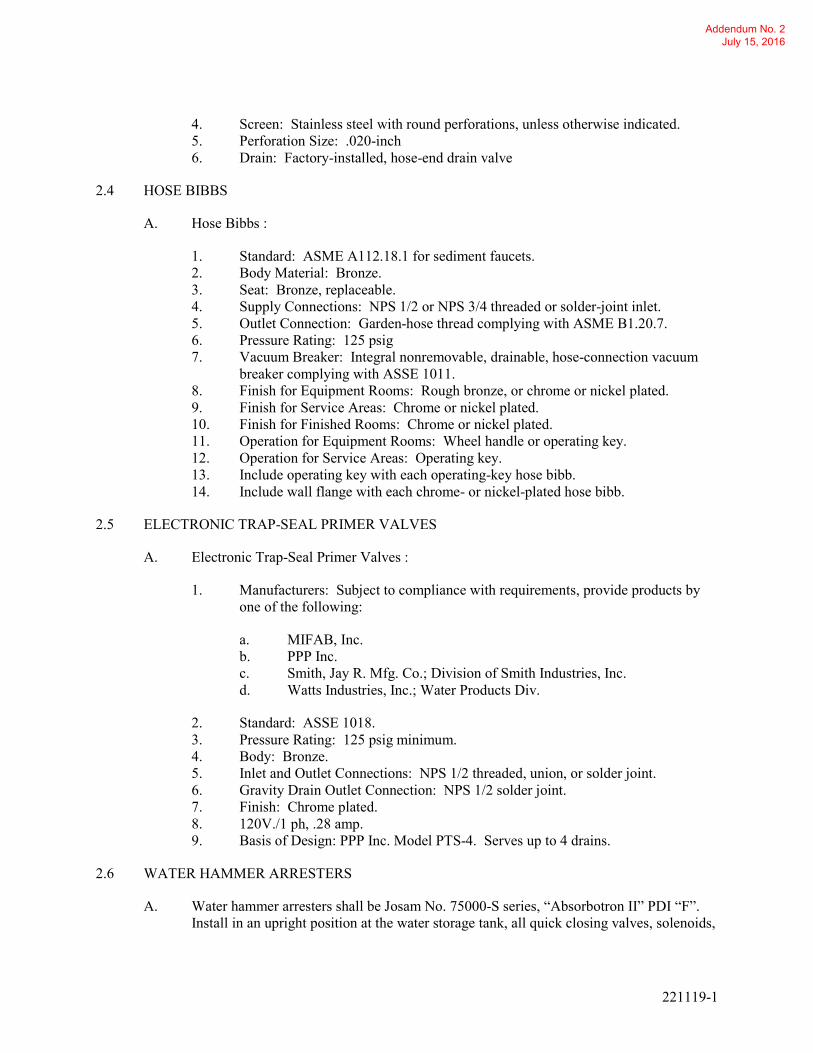
221119-1
4. Screen: Stainless steel with round perforations, unless otherwise indicated.
5. Perforation Size: .020-inch
6. Drain: Factory-installed, hose-end drain valve
2.4 HOSE BIBBS
A. Hose Bibbs :
1. Standard: ASME A112.18.1 for sediment faucets.
2. Body Material: Bronze.
3. Seat: Bronze, replaceable.
4. Supply Connections: NPS 1/2 or NPS 3/4 threaded or solder-joint inlet.
5. Outlet Connection: Garden-hose thread complying with ASME B1.20.7.
6. Pressure Rating: 125 psig
7. Vacuum Breaker: Integral nonremovable, drainable, hose-connection vacuum
breaker complying with ASSE 1011.
8. Finish for Equipment Rooms: Rough bronze, or chrome or nickel plated.
9. Finish for Service Areas: Chrome or nickel plated.
10. Finish for Finished Rooms: Chrome or nickel plated.
11. Operation for Equipment Rooms: Wheel handle or operating key.
12. Operation for Service Areas: Operating key.
13. Include operating key with each operating-key hose bibb.
14. Include wall flange with each chrome- or nickel-plated hose bibb.
2.5 ELECTRONIC TRAP-SEAL PRIMER VALVES
A. Electronic Trap-Seal Primer Valves :
1. Manufacturers: Subject to compliance with requirements, provide products by
one of the following:
a. MIFAB, Inc.
b. PPP Inc.
c. Smith, Jay R. Mfg. Co.; Division of Smith Industries, Inc.
d. Watts Industries, Inc.; Water Products Div.
2. Standard: ASSE 1018.
3. Pressure Rating: 125 psig minimum.
4. Body: Bronze.
5. Inlet and Outlet Connections: NPS 1/2 threaded, union, or solder joint.
6. Gravity Drain Outlet Connection: NPS 1/2 solder joint.
7. Finish: Chrome plated.
8. 120V./1 ph, .28 amp.
9. Basis of Design: PPP Inc. Model PTS-4. Serves up to 4 drains.
2.6 WATER HAMMER ARRESTERS
A. Water hammer arresters shall be Josam No. 75000-S series, “Absorbotron II” PDI “F”.
Install in an upright position at the water storage tank, all quick closing valves, solenoids,
Addendum No. 2 July 15, 2016

221119-1
and plumbing fixtures. Locate and size as indicated on the drawings. Where not shown
on drawings, locate and size in accordance with the Plumbing and Drainage Institute
Standard No. WH201.
PART 3 - EXECUTION
3.1 INSTALLATION
A. Refer to Division 22 Section "Common Work Results for Plumbing" for piping joining
materials, joint construction, and basic installation requirements.
B. Install backflow preventers in each water supply to mechanical equipment and systems
and to other equipment and water systems that may be sources of contamination.
Comply with authorities having jurisdiction.
1. Locate backflow preventers in same room as connected equipment or system.
2. Install drain for backflow preventers with atmospheric-vent drain connection
with air-gap fitting, fixed air-gap fitting, or equivalent positive pipe separation of
at least two pipe diameters in drain piping and pipe to floor drain. Locate air-gap
device attached to or under backflow preventer. Simple air breaks are not
acceptable for this application.
3. Do not install bypass piping around backflow preventers.
C. Install balancing valves in locations where they can easily be adjusted.
D. Install temperature-actuated water mixing valves with check stops or shutoff valves on
inlets and with shutoff valve on outlet.
1. Install thermometers and water regulators if specified.
2. Install cabinet-type units recessed in or surface mounted on wall as specified.
E. Install Y-pattern strainers for water on supply side of each balancing valve and pump.
One-treated-wood blocking is specified in Division 6 Section "Rough Carpentry."
F. Install water hammer arresters in water piping according to PDI-WH 201.
G. Provide disposable fine mesh screen for to fit over cylinder strainer for initial startup.
Remove after initial startup.
3.2 CONNECTIONS
A. Piping installation requirements are specified in other Division 22 Sections. Drawings
indicate general arrangement of piping and specialties.
3.3 LABELING AND IDENTIFYING
A. Equipment Nameplates and Signs: Install engraved plastic-laminate equipment
nameplate or sign on or near each of the following:
Addendum No. 2 July 15, 2016

221119-1
1. Reduced Pressure Principle backflow-prevention assemblies.
B. Distinguish among multiple units, inform operator of operational requirements, indicate
safety and emergency precautions, and warn of hazards and improper operations, in
addition to identifying unit. Nameplates and signs are specified in Division 22 Section
"Identification for Plumbing Piping and Equipment."
3.4 FIELD QUALITY CONTROL
A. Perform the following tests and prepare test reports:
1. Test each backflow-prevention assembly according to authorities having
jurisdiction and the device's reference standard.
B. Remove and replace malfunctioning domestic water piping specialties and retest as
specified above.
3.5 ADJUSTING
A. Set field-adjustable pressure set points of water pressure-reducing valves.
B. Set field-adjustable flow set points of balancing valves.
C. Set field-adjustable temperature set points of temperature-actuated water mixing valves.
END OF SECTION 221119
Addendum No. 2 July 15, 2016

221316-1
SECTION 221316
SANITARY WASTE AND VENT PIPING
PART 1 - GENERAL
1.1 SUMMARY
A. Section Includes:
1. Sanitary Waste and Vent piping above and below grade.
2. Cleaning new sanitary piping system
B. Related Sections:
1. Division 22 Section “Identification for Plumbing Piping and Equipment”.
2. Division 22 Section “Hangers and Supports for Plumbing Piping and
Equipment”.
1.2 REFERENCES
A. American Society of Mechanical Engineers:
1. ASME B16.1 - Cast Iron Pipe Flanges and Flanged Fittings.
2. ASME B16.3 - Malleable Iron Threaded Fittings.
3. ASME B16.4 - Gray Iron Threaded Fittings.
B. ASTM International:
1. ASTM A47/A47M - Standard Specification for Ferritic Malleable Iron Castings.
2. ASTM A53/A53M - Standard Specification for Pipe, Steel, Black and Hot-
Dipped, Zinc-Coated, Welded and Seamless.
3. ASTM A74 - Standard Specification for Cast Iron Soil Pipe and Fittings.
4. ASTM C564 - Standard Specification for Rubber Gaskets for Cast Iron Soil Pipe
and Fittings.
5. ASTM F708 - Standard Practice for Design and Installation of Rigid Pipe
Hangers.
6. ASTM F1476 - Standard Specification for Performance of Gasketed Mechanical
Couplings for Use in Piping Applications.
C. Cast Iron Soil Pipe Institute:
1. CISPI 301 - Standard Specification for Hubless Cast Iron Soil Pipe and Fittings
for Sanitary and Storm Drain, Waste, and Vent Piping Applications.
2. CISPI 310 - Specification for Coupling for Use in Connection with Hubless Cast
Iron Soil Pipe and Fittings for Sanitary and Storm Drain, Waste, and Vent Piping
Applications.
Addendum No. 2 July 15, 2016

221316-2
D. Manufacturers Standardization Society of the Valve and Fittings Industry:
1. MSS SP 58 - Pipe Hangers and Supports - Materials, Design and Manufacturer.
2. MSS SP 69 - Pipe Hangers and Supports - Selection and Application.
3. MSS SP 89 - Pipe Hangers and Supports - Fabrication and Installation Practices.
E. Plumbing and Drainage Institute:
1.3 SUBMITTALS
A. Division 01 - Submittal Procedures: Submittal procedures.
B. Shop Drawings: Indicate dimensions, weights, and placement of openings and holes.
C. Product Data:
1. Piping: Submit data on pipe materials, fittings, and accessories. Submit
manufacturers catalog information.
2. Hangers and Supports: Submit manufacturers catalog information including load
capacity.
3. Sanitary Drainage Specialties: Submit manufacturers catalog information,
component sizes, rough-in requirements, service sizes, and finishes.
D. Manufacturer's Installation Instructions: Submit installation instructions for material and
equipment.
E. Manufacturer's Certificate: Certify products meet or exceed specified requirements.
1.4 CLOSEOUT SUBMITTALS
A. Division 01 - Execution Requirements: Closeout procedures.
B. Project Record Documents: Record actual locations of equipment and clean-outs.
1.5 QUALIFICATIONS
A. Manufacturer: Company specializing in manufacturing products specified in this section
with minimum ten years documented experience.
B. Installer: Company specializing in performing Work of this section with minimum five
years documented experience.
1.6 DELIVERY, STORAGE, AND HANDLING
A. Division 01 - Product Requirements: Product storage and handling requirements.
B. Protect piping systems from entry of foreign materials by temporary covers, completing
sections of the Work, and isolating parts of completed system.
Addendum No. 2 July 15, 2016
221316-3
1.7 ENVIRONMENTAL REQUIREMENTS
A. Division 01 - Product Requirements.
1.8 FIELD MEASUREMENTS
A. Verify field measurements prior to fabrication.
1.9 WARRANTY
A. Division 01 - Execution Requirements: Product warranties and product bonds.
1.10 EXTRA MATERIALS
A. Division 01 - Execution Requirements: Spare parts and maintenance products.
PART 2 - PRODUCTS
2.1 PIPING MATERIALS
A. Above Grade Sanitary and Vent Pipe outside of the Wash Bay: Service Weight Cast-Iron
Pipe and Fittings with Hub connections: ASTM A 888 or CISPI 301. Neoprene
compression Tyler Ty-Seal connections.
B. Above Grade Sanitary and Vent Piping inside the Wash Bay: Type 304 Schedule 40
Stainless Steel with Sanitary fittings. Threaded connections.
C. Below Grade Sanitary and Vent Pipe 4” diameter and below: Extra heavy Weight Cast
Iron pipe and fittings ASTM A88 or CISPI301 with neoprene compression gasket Ty-
Seal type joints.
D. Below Grade Sanitary and Vent Pipe 6” diameter and above: Ductile Iron. Tyler Tyseal
connections.
E. Above Grade Sanitary and Vent Pipe outside the Wash Bay: Copper DWV hard temper
seamless copper type ASTM B306 with lead free soldered joints. Fittings to be cast
bronze lead free soldered drainage joints, ANSI B16.23 or wrought copper ANSI B16.29
F. Above grade vent piping outside the Wash Bay: Schedule 40 galvanized steel pipe
ASTM A53 or A106, Grade A or B. Threaded joints. Fittings Standard weight
galvanized cast iron screwed drainage fittings Type ANSI B16.12, ASTM A126.
2.2 FLOOR DRAINS
A. Type “A” (Industrial bottom outlet for unfinished spaces)
1. Description: Coated cast iron with double drainage flange, non-puncturing
flashing clamp collar, weep holes, bottom outlet, inside caulk connection, round
Addendum No. 2 July 15, 2016

221316-4
top, and removable deep sediment bucket with integral drainage rim so designed
that grate cannot be set in place unless bucket is in position.
2. Grate: Heavy duty ductile iron grate suitable for fork truck traffic.
3. Trap: Deep seal "P" trap.
4. Floor drain shall be Watts FD-340-Y-SET
2.3 CLEANOUTS
A. General
1. Cleanouts inside the building shall be gas tight. Where cleanouts are on buried
or concealed lines, they shall extend flush to the finished floor or grade. Provide
"T" handle for removal of cleanout plugs.
2. Floor Cleanouts:
a. Cleanouts shall consist of "Y" fittings full size of pipe to 4" in diameter
and not less than 4" for larger sizes. Recessed plug shall be bronze with
rectangular countersunk slot. Cover shall be secured extra heavy duty
ductile iron suitable for fork truck traffic. Provide "T" handle for
recessed plug. Cleanout shall be Josam Series 55000-5-VP, or similar by
Wade, Smith, Zurn, or Watts.
3. Wall Cleanouts
a. Cleanouts shall consist of "Y" fittings full size of pipe to 4" in diameter
and not less than 4" for larger sizes. Plug shall be bronze with
rectangular countersunk slot. Provide "T" handle for recessed plug.
Provide cover with nail anchors. Frame and cover shall be polished
bronze. Cover shall be Josam Series 58600, or similar by Wade, Smith,
Zurn, or Watts.
4. Exterior Cleanouts (for gravity lines)
a. Cleanouts shall consist of "Y" fittings full size of pipe to 4" in diameter
and not less than 4" for larger sizes. Recessed plug shall be tapered
thread bronze with rectangular countersunk slot. Cleanout ferrule to be
cast iron. The cleanout cover frame shall be centered in a 20" square,
11" thick concrete pad. Cover shall be secured extra heavy duty ductile
iron suitable for highway traffic. Cleanout shall be Josam Series 58850
with coated cast iron ferrule and bronze plug, or similar by Wade, Smith,
Zurn, or Watts.
PART 3 - EXECUTION
3.1 EXAMINATION
A. Division 01 - Administrative Requirements: Coordination and project conditions.
Addendum No. 2 July 15, 2016

221316-5
B. Verify excavations are to required grade, dry, and not over-excavated.
3.2 PREPARATION
A. Remove scale and dirt, on inside and outside, before assembly.
B. Prepare piping connections to equipment with flanges or unions.
C. Keep open ends of pipe free from scale and dirt. Protect open ends with temporary plugs
or caps.
3.3 PIPING APPLICATIONS
A. Special pipe fittings with pressure ratings at least equal to piping pressure ratings may be
used in applications below, unless otherwise indicated.
B. Flanges and unions may be used on aboveground pressure piping, unless otherwise
indicated.
C. Aboveground, soil, waste, and vent piping NPS 4 and smaller shall be hub cast-iron soil
pipe and fittings; neoprene Tyler Ty-Seal gaskets.
3.4 PIPING INSTALLATION
A. Basic piping installation requirements are specified in Division 22 Section "Common
Work Results for Plumbing."
B. Install sleeve with water stop and mechanical sleeve seal at each service pipe penetration
through foundation wall. Select number of interlocking rubber links required to make
installation watertight. Sleeves and mechanical sleeve seals are specified in Division 22
Section "Sleeve and Sleeve Seals for Plumbing Piping."
C. Install cast-iron soil piping according to CISPI's "Cast Iron Soil Pipe and Fittings
Handbook," Chapter IV, "Installation of Cast Iron Soil Pipe and Fittings."
D. Make changes in direction for soil and waste drainage and vent piping using appropriate
branches, bends, and long-sweep bends. Sanitary tees and short-sweep 1/4 bends may be
used on vertical stacks if change in direction of flow is from horizontal to vertical. Use
long-turn, double Y-branch and 1/8-bend fittings if 2 fixtures are installed back to back or
side by side with common drain pipe. Straight tees, elbows, and crosses may be used on
vent lines. Do not change direction of flow more than 90 degrees. Use proper size of
standard increasers and reducers if pipes of different sizes are connected. Reducing size
of drainage piping in direction of flow is prohibited.
E. Install soil and waste drainage and vent piping at the following minimum slopes, unless
otherwise indicated:
1. Horizontal Sanitary Drainage Piping: 2 percent downward in direction of flow.
2. Vent Piping: 1 percent down toward vertical fixture vent or toward vent stack.
Addendum No. 2 July 15, 2016

221316-6
F. Do not enclose, cover, or put piping into operation until it is inspected and approved by
authorities having jurisdiction.
3.5 JOINT CONSTRUCTION
A. Basic piping joint construction requirements are specified in Division 22 Section
"Common Work Results for Plumbing."
B. Cast-Iron, Soil-Piping Joints: Make joints according to CISPI's "Cast Iron Soil Pipe and
Fittings Handbook," Chapter IV, "Installation of Cast Iron Soil Pipe and Fittings."
1. Hub Joints: Make with neoprene gasket.
3.6 HANGER AND SUPPORT INSTALLATION
A. Pipe hangers and supports are specified in Division 22 Section "Hangers and Supports for
Plumbing Piping and Equipment." Install the following:
1. Vertical Piping: MSS Type 8 or Type 42, clamps.
2. Individual, Straight, Horizontal Piping Runs: According to the following:
a. 100 Feet and Less: MSS Type 1, adjustable, steel clevis hangers.
b. Longer than 100 Feet: MSS Type 43, adjustable roller hangers.
3. Multiple, Straight, Horizontal Piping Runs 100 Feet or Longer: MSS Type 44,
pipe rolls. Support pipe rolls on trapeze.
4. Use all Type 304 Stainless steel materials for hangers and supports in the Wash
Bay area.
B. Install supports according to Division 22 Section "Hangers and Supports for Plumbing
Piping and Equipment."
C. Rod diameter may be reduced 1 size for double-rod hangers, with 3/8-inch minimum
rods.
D. Install hangers for cast-iron soil piping with the following maximum horizontal spacing
and minimum rod diameters:
1. NPS 1-1/2 and NPS 2: 60 inches with 3/8-inch rod.
2. NPS 3: 60 inches with 1/2-inch rod.
3. NPS 4 and NPS 5: 60 inches with 5/8-inch rod.
E. Install supports for vertical cast-iron soil piping every 15 feet.
F. Support piping and tubing not listed above according to MSS SP-69 and manufacturer's
written instructions.
Addendum No. 2 July 15, 2016
221316-7
3.7 CONNECTIONS
A. Connect soil and waste piping to exterior sanitary sewerage piping. Use transition fitting
to join dissimilar piping materials.
B. Connect drainage and vent piping to the following:
1. Equipment: Connect atmospheric vent piping in sizes indicated, but not smaller
than required by authorities having jurisdiction.
2. Plumbing Specialties: Connect drainage and vent piping in sizes indicated, but
not smaller than required by plumbing code.
3.8 FIELD QUALITY CONTROL
A. During installation, notify authorities having jurisdiction at least 24 hours before
inspection must be made. Perform tests specified below in presence of authorities having
jurisdiction.
1. Roughing-in Inspection: Arrange for inspection of piping before concealing or
closing-in after roughing-in and before setting fixtures.
2. Final Inspection: Arrange for final inspection by authorities having jurisdiction
to observe tests specified below and to ensure compliance with requirements.
B. Reinspection: If authorities having jurisdiction find that piping will not pass test or
inspection, make required corrections and arrange for reinspection.
C. Reports: Prepare inspection reports and have them signed by authorities having
jurisdiction.
D. Test sanitary drainage and vent piping according to procedures of authorities having
jurisdiction.
1. Repair leaks and defects with new materials and retest piping, or portion thereof,
until satisfactory results are obtained.
2. Prepare reports for tests and required corrective action.
3.9 CLEANING
A. Clean interior of piping. Remove dirt and debris as work progresses.
B. Protect drains during remainder of construction period to avoid clogging with dirt and
debris and to prevent damage from traffic and construction work.
C. Place plugs in ends of uncompleted piping at end of day and when work stops.
D. Following the installation of the sanitary piping system and overall construction, the
sanitary piping system (both existing and new) which is connected to sanitary piping
installed under this contract shall be jet cleaned to remove debris from the piping system.
Addendum No. 2 July 15, 2016

221316-8
3.10 FIELD QUALITY CONTROL
A. Division 01 - Execution Requirements: Field inspecting, testing, adjusting, and balancing.
B. Test sanitary waste and vent piping system in accordance with applicable code and local
authority having jurisdiction.
END OF SECTION 221316
Addendum No. 2 July 15, 2016

221323 - 1
SECTION 221323
SANITARY WASTE INTERCEPTORS
PART 1 - GENERAL
1.1 RELATED DOCUMENTS
A. Drawings and general provisions of the Contract, including General and Supplementary
Conditions and Division 01 Specification Sections, apply to this Section.
1.2 SUMMARY
A. Section Includes:
1. Oil interceptors.
1.3 REFERENCE STANDARDS
A. AASHTO - American Association of State Highway and Transportation Officials
B. ANSI - American National Standards Institute
C. API - American Petroleum Institute
D. ASTM - American Society for Testing and Materials
1. ASTM Standard Specification for Carbon Structural Steel - ASTM International.
E. AWS - American Welding Society
1. Structural Welding Code – Steel.
F. NEC - National Electric Code
G. NEMA - National Electric Manufacturers Association
H. NFPA - National Fire Protection Association
1. NFPA 30, Flammable and Combustible Liquids Code;
2. NFPA 70, NEC National Electric Code.
I. OSHA - U. S. Department of Labor, Occupational Safety and Health Administration
1. OSHA 29 CFR 1910.106, Occupational Safety and Health Standards, particularly
Flammable and Combustible Liquids.
J. PEI - Petroleum Equipment Institute.
Addendum No. 2 July 15, 2016

221323 - 2
1. RP100, Recommended Practices for Installation of Underground Liquid Storage
Systems.
K. SSPC - Steel Structures Painting Council/NACE - National Association of Corrosion
Engineers.
1. SSPC-SP 6/NACE No. 3, Commercial Blast Cleaning.
2. SSPC-SP 10/NACE No. 2, Near-White Blast Cleaning.
L. STI - Steel Tank Institute
M. UL - Underwriters Laboratories, Inc.
1. UL 58 - Steel Underground Tanks for Flammable and Combustible Liquids;
2. UL 1746 - Corrosion Protection of Underground Tanks;
3. UL SU2215 - OWS Design, Construction, and Performance Standards.
N. U.S. Code of Federal Regulations (CFR) Title 33 and Title 40
1. Oil Pollution Act (Title 33 U.S.C. 2701 ET SEQ.; 104 STAT. 484);
2. Clean Water Act (Title 40 Effluent Guidelines and Standards).
O. U.S. EPA - United States Environmental Protection Agency
1. EPA Test Method 1664A - Oil and Grease Recoverable Extraction.
1.4 SUBMITTALS
A. Comply with Section 01 33 00 - Submittal Procedures.
B. Shop Drawings: Submit shop drawings of the coalescing oil/water separator(s) by the
manufacturer showing principal dimensions and location of all fittings.
C. Product Data: Submit manufacturer’s product data, including installation, operation, and
maintenance instructions.
D. Quality Control: Quality control, inspection procedures, and reports shall be considered
part of the submittal package.
E. Manufacturer’s Certification: Submit manufacturer’s certification that the coalescing
oil/water separator(s) comply with specified requirements and are suitable for intended
application.
F. Warranty Documentation: Submit manufacturer’s standard warranty.
1.5 QUALITY ASSURANCE
A. Manufacturer’s Qualifications:
Addendum No. 2 July 15, 2016
221323 - 3
1. Manufacturer regularly engaged, for past 20 years, in manufacture of coalescing
oil/water separator(s) of similar type to that specified. No subcontracting of
oil/water separator(s) fabrication shall be permitted.
2. Manufacturer shall be able to provide written documentation from Underwriter’s
Laboratories, Inc. that the separator has been fabricated and tested to the
applicable requirements of Underwriters Laboratories, Inc. UL SU2215.
3. Manufacturer shall provide written documentation that the oil/water separator
was “Made in USA.” The product must be "all or virtually all" fabricated in the
United States, including the 50 states, the District of Columbia, and the U.S.
territories and possessions.
4. Verification and Inspection:
a. Verification of manufacturing location.
b. Inspection during manufacturer’s welding operations.
c. Inspection during manufacturer’s coating operation.
d. Review of QA/QC Documentation.
5. Manufacturer shall provide inspector with a minimum of fourteen (14) days
advanced notice prior to when the in-process inspection point is scheduled to
occur.
B. Installer's Qualifications:
1. Installer regularly engaged, for past 5 years, in installation of coalescing oil/water
separator(s) of similar type to that specified.
2. Employ persons qualified for proper installation of coalescing oil/water
separator(s).
1.6 DELIVERY, STORAGE, AND HANDLING
A. Deliver, store, and handle coalescing oil/water separator(s) in accordance with
manufacturer’s instructions.
B. Protect coalescing oil/water separator(s) during delivery, storage, handling, and
installation to prevent damage.
1.7 WARRANTY PERIOD
A. The manufacturer shall:
1. Warrant its products to be free from defects in material and workmanship for a
period of one (1) year from the date of shipment. The warranty shall be limited
to repair or replacement of the defective part(s).
2. Supply a ten (10) year limited warranty against external corrosion on terms
provided by manufacturer.
Addendum No. 2 July 15, 2016
221323 - 4
1.8 FIELD CONDITIONS
A. Interruption of Existing Sewer Services: Do not interrupt services to facilities occupied
by Owner or others unless permitted under the following conditions and then only after
arranging to provide temporary sewer services according to requirements indicated:
1. Notify Owner no fewer than seven days in advance of proposed interruption of
service.
2. Do not proceed with interruption of sewer services without Owner's written
permission.
PART 2 - PRODUCTS
2.1 COALESCING OI/WATER SEPARATORS
A. Manufacturers: Subject to compliance with requirements, available manufacturers
offering products that may be incorporated into the Work include, but are not limited to,
the following:
1. Highland Tank
B. Coalescing Oil/Water Separator(s) shall be designed for gravity separation of sand, grit,
settleable solids or semisolids and free oils (hydrocarbons and other petroleum products)
from wastewater associated with truck wash facility operations.
1. Separator shall be installed underground with top access near or above grade
level.
C. Separator(s) shall be equipped with an Integral Sand Interceptor Compartment at the inlet
of the oil/water separator to permit sand and grit to settle out before the wastewater enters
the Oil/Water Separation Compartment.
D. Nominal Oil/Water Separator Compartment Capacity 4,000-gallons, as indicated on the
drawings.
E. Nominal Integral Sand Interceptor Compartment Capacity: 627-gallons, as indicated on
the drawings.
1. Sand Interceptor Compartment is integral to the oil/water separator and is
hydraulically designed to remove up to 80% of the sand and grit materials from
the storm water runoff by gravity settling prior to entering the Oil/Water
Separation Compartment. The capacity of the compartment is consistent with
industry protocols therefore a separator of smaller volume with a smaller
compartment is not permissible.
F. Maximum Flow Rate: 400-gallons/minute, as indicated on the drawings.
G. Conformance
Addendum No. 2 July 15, 2016
221323 - 5
1. Oil/Water Separator Corrosion Control System shall be in strict accordance with
Underwriters Laboratories, Inc. Subject UL 1746 Standard for External
Corrosion Protection Systems for Steel Underground Storage Tanks and
HighGuard External Corrosion Protection Specifications.
2. Oil/Water Separator volume shall allow for a nominal hydraulic retention time of
ten (10) minutes.
a. Oil/Water Separator volume has been calculated to ensure laminar flow
conditions which result in hydraulic uniformity and high effluent quality.
b. Volume reduction will adversely affect separator performance by
increasing horizontal velocity and turbulence, therefore a separator of
smaller volume is not permissible.
3. To prevent extensive shutdown and maintenance, the oil/water separator’s
coalescer design must allow solids to fall unhindered by turbulence, and oil
droplets to rise, without risk of re-emulsifying due to collisions with interfering
solids.
a. The use of plastic perforated tubes, spherical balls, or irregular shaped
media will increase the facility’s maintenance costs and shall not be
permitted.
H. Construction:
1. Oil/Water Separator shall be cylindrical, horizontal, atmospheric-type steel vessel
intended for the separation and storage of flammable and combustible liquids.
2. The oil/water separator shall be a pre-packaged, pre-engineered, ready to install
unit consisting of:
a. Nozzle discharge to be located at the furthest diagonal point from the
effluent discharge opening.
b. An internal influent nozzle at the inlet end of the separator.
3. The oil/water separator shall contain a 627-gallon Integral Sand Interceptor
Compartment with:
a. One (1) 24-inch diameter manways, UL approved, complete with ______
extension, cover, gasket and bolts, to facilitate access into Sand
Interceptor Compartment for solids removal. (Manway extension length
determined by burial depth.)
b. A heavy-duty bulkhead to retain sand, grit, settleable solids or semisolids
and prevent them from entering the Oil/Water Separator Compartment.
4. The transfer pipe shall discharge to the Sediment Chamber with:
a. A Velocity Head Diffusion Baffle at the inlet to:
1) Reduce horizontal velocity and flow turbulence.
Addendum No. 2 July 15, 2016

221323 - 6
2) Distribute the flow equally over the separators cross sectional
area.
3) Direct the flow in a serpentine path in order to enhance hydraulic
characteristics and fully utilize all separator volume.
4) Completely isolate all inlet turbulence from the Oil/Water
Separation Chamber.
5. A Sediment Chamber to disperse flow and collect oily solids and sediments.
6. A Sludge Baffle to retain settleable solids and sediment and prevent them from
entering the Oil/Water Separation Chamber.
7. An Oil/Water Separation Chamber containing a removable inclined parallel
flat/corrugated plate coalescer.
a. The coalescer shall have individual removable plates, sloped towards the
Sediment Chamber.
b. Each coalescing plate shall be flat on the top and corrugated on the
bottom. The flat top plate shall resist clogging and clotting with solids to
minimize the facility’s maintenance costs.
c. The corrugations of each of the plate bottoms shall be shaped and
positioned to enhance collisions between the rising oil droplets and
coalescence between them thereby improving separator efficiency.
8. The Oil/Water Separation Chamber shall also contain a sectionalized removable
"Petro-Screen" polypropylene impingement coalescer designed to intercept oil
globules of 20 microns in diameter and larger.
a. Heavy, one-piece impingement coalescers are not permissible for safety
reasons.
9. An internal effluent downcomer at the outlet end of the separator, to allow for
discharge from the bottom of the Oil/Water Separation Chamber only.
10. An effluent connection 8-inch, flanged.
11. Fittings for vent, interface/oil level sensor, waste oil pump-out, and gauge.
12. Two (2) 24-inch diameter manways, UL approved, cover, gasket and bolts.
(Manway extension length determined by burial depth.). Provide extension to
grade as required.
a. One manway shall be placed between the inlet and the parallel
flat/corrugated plate coalescer to facilitate access into Sediment Chamber
for solids removal.
b. One manway shall be placed between the parallel flat/corrugated plate
coalescer and outlet to facilitate access into the Oil/Water Separation
Chamber for oil removal.
13. Lifting lugs at balancing points for handling and installation.
14. Identification plates: Plates to be affixed in prominent location and be durable
and legible throughout equipment life.
15. Threaded NPT Fittings: Threaded fittings with thread protectors shall be supplied
as follows:
Addendum No. 2 July 15, 2016
221323 - 7
a. One (1), 2-inch Diameter: Interface/Oil Level Sensor
b. One (1), 2-inch Diameter: Normal Vent (per manway in manway
extension)
c. One (1), 4-inch Diameter: Oil/Sludge Level Gauging (per manway in
manway cover)
d. One (1), 4-inch Diameter: Oil Pump-Out
I. Corrosion Protection System:
1. Exterior Protective Coating:
a. Surface Preparation: Steel Grit Blast - SSPC-SP 6/NACE No. 3
Commercial Blast Cleaning.
b. External surfaces coated with 75 mils DFT HighGuard Self-Reinforcing
Polyurethane.
c. Polyurethane coating shall have a high cross-link density, which is, in
essence, self-reinforcing or self-fibrating. Artificial fillers or
reinforcement (chopped fiberglass or roving) shall not be permitted.
d. Coating shall be subjected to a 15,000 volt spark test after application to
ensure coating integrity and effective corrosion protection.
2. Internal Protective Lining:
a. Surface Preparation: Steel Grit Blast - SSPC-SP 10/NACE No. 2, Near-
White Blast Cleaning.
b. Internal surfaces coated with 15 mils DFT solvent-free, two component
polyurethane lining. The lining must comply with UL SU2215 and be
subjected to the required Physical Properties, Corrosion Resistance,
Permeation, and Impact Tests.
3. Options and Accessories
a. UL listed and UL SU2215 approved Interface/Oil Level Sensor and
Controls.
1) Oil/Water Separator shall be supplied with an audible and visual
alarm system that indicates high level and high-high level
(audible and visual) of accumulated oil in the oil/water separator
2) A silence control shall be provided for the audible alarms
3) Power shall be 115V/1 phase.
b. Hold-down Straps. When oil/water separator(s) anchoring is required.
1) Quantity as determined by manufacturer.
2) Polyester corrosion resistant, hold-down straps with turnbuckles
and a cable restraint system will be provided.
3) Steel hold-down straps with neoprene liners shall be provided
where polyester straps are not applicable.
Addendum No. 2 July 15, 2016

221323 - 8
c. Prefabricated Concrete Deadman Anchors.
1) Quantity as determined by manufacturer.
2) Pre-engineered and pre-fabricated concrete deadman anchors
may be an acceptable means of anchoring the oil/water
separator(s) provided buoyancy calculations are submitted and
signed by an engineer of the separator manufacturer.
3) The concrete deadman anchors must be supplied by the separator
manufacturer and have been a standard product for at least five
years.
4) All pre-fabricated concrete deadman anchors shall be sized and
installed in accordance with the separator manufacturer’s
guidelines.
d. Manufacturer On-Site Training Assistance
1) On-site training will be included. This project requires Factory
Personnel/Factory Representative to perform on-site training
upon completion of field wiring and filling of oil/water
separator(s).
PART 3 - EXECUTION
3.1 INSTALLATION
A. No modifications shall be made to the oil/water separator(s) without the prior written
approval of the manufacturer and the Engineer. This includes any welding on separator
shells, adding penetrations, modifying the separator structure, or repairing damage that
might affect the integrity of the oil/water separator(s).
B. Contractor shall install oil/water separator(s), piping, and equipment (inlet/outlet shut off
valves, sensors, pumps, vents, gauges, etc.) in accordance with the manufacturers'
installation instructions, industry standard recommended practices and federal, state and
local regulations.
C. Oil/Water Separator(s) shall be handled, lifted, stored, and secured in accordance with the
manufacturer’s instructions.
D. The hazards associated with the cleaning, entry, inspection, testing, maintenance or other
aspects of oil/water separator(s) are significant. Safety considerations and controls
should be established prior to undertaking physical activities associated with oil/water
separator(s).
1. Never enter an OWS or enclosed space, under any condition, without proper
training and OSHA approved equipment. (Consult OSHA regulation 29 CFR
1910.146 “Permit Required Confined Spaces.”)
2. Entry and cleaning of oil/water separator(s) must be per federal (OSHA), state,
and local regulations as well as company requirements.
Addendum No. 2 July 15, 2016
221323 - 9
E. Familiarity with the Site.
1. Contractor shall familiarize self with the location of all public utility facilities
and structures that may be found in the vicinity of the construction.
2. The Contractor shall conduct his operation to avoid damage to the utilities or
structures.
3. The Contractor is responsible for meeting all the requirements established by the
agencies for utility work, as well as work affecting utilities and other government
agencies.
3.2 EXAMINATION
A. Notify site supervisor or engineer of conditions that would adversely affect installation.
B. Do not begin installation until unacceptable conditions are corrected.
3.3 PREPARATION
A. Before Placing Oil/Water Separator(s) in excavation:
1. Remove dirt clods and similar foreign matter from oil/water separator(s).
2. Visually inspect oil/water separator(s) for damage.
3. Notify site supervisor of damage to oil/water separator(s).
4. Repair or spark test damaged areas of oil/water separator coating in accordance
with manufacturer’s instructions in Oil/Water Separator Users’ Manual.
3.4 INSTALLATION
A. Install oil/water separator in accordance with manufacturer’s instructions.
B. Install underground oil/water separator(s) at locations and to elevations indicated on the
Drawings.
C. Ensure oil/water separator(s) excavation is free from materials that may cause damage to
oil/water separator(s) or separator’s coating.
D. Do not allow foreign matter to be introduced into excavation or backfill during oil/water
separator(s) installation.
E. Bottom of Excavation: Cover with clean sand or gravel to depth indicated on the
Drawings, suitably graded and leveled.
F. Oil/Water Separator(s) Handling:
1. Ensure equipment to handle oil/water separator(s) is of adequate size to lift and
lower oil/water separator(s) without dragging, dropping, or damaging oil/water
separator or separator coating.
2. Carefully lift and lower oil/water separator(s) with cables or chains of adequate
length attached to lifting lugs provided.
Addendum No. 2 July 15, 2016

221323 - 10
3. Use spreader bar where necessary.
4. Do not use chains or slings around oil/water separator shell.
5. Maneuver oil/water separator with guidelines attached to each end of the
separator.
G. Hold-Down Straps
1. Install polyester hold-down in accordance with manufacturer’s instructions
2. If steel hold-down straps are used, ensure hold-down straps are separated from
oil/water separator by separating pads made of inert, insulation dielectric
material.
3. Separating Pads:
a. Minimum two inches wider than width of hold-down straps.
b. Place separating pads at locations on oil/water separator where hold-
down straps could come into direct contact with oil/water separator shell.
H. Backfill:
1. Backfill Material: Clean sand, ASTM D 448 #8 crushed aggregate or fine gravel.
2. Place backfill material along bottom side of oil/water separator(s) by shoveling
and tamping to ensure oil/water separator(s) are fully and evenly supported
around bottom quadrant.
3. Deposit backfill material carefully around and over oil/water separator(s) to
avoid damage to oil/water separator(s) and separator coating.
4. Deposit backfill material to depth over oil/water separator(s) as indicated on the
Drawings.
I. Before Placing Backfill Over Oil/Water Separator(s):
1. Final Inspection: Visually inspect oil/water separator(s), separator coating, and
pipe connections.
3.5 ELECTRICAL
A. Installation of all electrical components including (Electric level sensors, alarm/control
panels, electronic actuated inlet/outlet shut off valves, pumps, etc.):
1. Installation shall be in accordance with manufacturers' installation instructions
and shall conform to state and local electrical codes with special attention to
compliance with requirements for work in classified areas.
3.6 PROTECTION
A. Protect installed underground steel storage oil/water separator(s) from damage during
construction.
Addendum No. 2 July 15, 2016

221323 - 11
3.7 START-UP, OPERATION AND MAINTENANCE
A. Oil/Water Separator(s) shall be started, operated and maintained according to the
manufacturer’s Oil/Water Separator Users’ Manual in effect at time of installation.
END OF SECTION 221323
Addendum No. 2 July 15, 2016
222114-1
SECTION 222114
FACILITY NATURAL-GAS PIPING
PART 1 - GENERAL
1.1 SUMMARY
A. Section Includes:
1. Pipes, tubes, and fittings.
2. Piping specialties.
3. Piping and tubing joining materials.
4. Valves.
5. Pressure regulators.
B. The gas piping system operates at a system pressure of 14 inches WC downstream of the
utility pressure regulator.
1.2 PERFORMANCE REQUIREMENTS
A. Minimum Operating-Pressure Ratings:
1. Piping and Valves: 100 psig minimum unless otherwise indicated.
2. Service Regulators: 100 psig minimum unless otherwise indicated.
B. Natural-Gas System Pressure within Buildings: 14 in. wc.
C. Natural gas pressure underground: 2 psig.
1.3 ACTION SUBMITTALS
A. Product Data: For each type of product indicated.
B. Shop Drawings: For facility natural-gas piping layout. Include plans, piping layout and
elevations, sections, and details for fabrication of pipe hangers, supports for multiple
pipes, and attachments of the same to building structure.
1.4 INFORMATIONAL SUBMITTALS
A. Welding certificates.
B. Field quality-control reports.
1.5 CLOSEOUT SUBMITTALS
A. Operation and maintenance data.
Addendum No. 2 July 15, 2016

222114-2
1.6 QUALITY ASSURANCE
A. Steel Support Welding Qualifications: Qualify procedures and personnel according to
AWS D1.1/D1.1M, "Structural Welding Code - Steel."
B. Pipe Welding Qualifications: Qualify procedures and operators according to ASME
Boiler and Pressure Vessel Code.
C. Electrical Components, Devices, and Accessories: Listed and labeled as defined in
NFPA 70, by a qualified testing agency, and marked for intended location and
application.
PART 2 - PRODUCTS
2.1 PIPES, TUBES, AND FITTINGS
A. Pipe outside of Wash Bay:
1. Pipe: ASTM A 53/A 53M, black steel, Schedule 40, Type E or S, Grade B.
2. Wrought-Steel Welding Fittings: ASTM A 234/A 234M for butt welding and
socket welding.
3. Unions: ASME B16.39, Class 150, malleable iron with brass-to-iron seat,
ground joint, and threaded ends.
B. Pipe inside Wash Bay:
1. Pipe: Type 304 Stainless Steel, Schedule 40
2. Fittings: Type 304 Stainless Steel, Schedule 40
3. Joints: Threaded
2.2 PIPING SPECIALTIES
A. Y-Pattern Strainers:
1. Body: ASTM A 126, Class B, cast iron with bolted cover and bottom drain
connection.
2. End Connections: Threaded ends for NPS 2 and smaller.
3. Strainer Screen: 60-mesh startup strainer, and perforated stainless-steel basket
with 50 percent free area.
4. CWP Rating: 125 psig.
B. Weatherproof Vent Cap: Cast- or malleable-iron increaser fitting with corrosion-resistant
wire screen, with free area at least equal to cross-sectional area of connecting pipe and
threaded-end connection.
2.3 JOINING MATERIALS
A. Joint Compound and Tape: Suitable for natural gas.
Addendum No. 2 July 15, 2016

222114-3
B. Welding Filler Metals: Comply with AWS D10.12/D10.12M for welding materials
appropriate for wall thickness and chemical analysis of steel pipe being welded.
2.4 MANUAL GAS SHUTOFF VALVES
A. See "Aboveground Manual Gas Shutoff Valve Schedule" Articles for where each valve
type is applied in various services.
B. Provide type 304 stainless steel valves where valves are connected to stainless steel pipe.
C. General Requirements for Metallic Valves, NPS 2 and Smaller: Comply with
ASME B16.33.
1. CWP Rating: 125 psig.
2. Threaded Ends: Comply with ASME B1.20.1.
3. Dryseal Threads on Flare Ends: Comply with ASME B1.20.3.
4. Tamperproof Feature: Locking feature for valves indicated in "Aboveground
Manual Gas Shutoff Valve Schedule" Articles.
5. Listing: Listed and labeled by an NRTL acceptable to authorities having
jurisdiction for valves 1 inch and smaller.
6. Service Mark: Valves shall have initials "WOG" permanently marked on valve
body.
D. One-Piece, Bronze Ball Valve with Bronze Trim: MSS SP-110.
1. Body: Bronze, complying with ASTM B 584.
2. Ball: Chrome-plated brass.
3. Stem: Bronze; blowout proof.
4. Seats: Reinforced TFE; blowout proof.
5. Packing: Separate packnut with adjustable-stem packing threaded ends.
6. Ends: Threaded, flared, or socket as indicated in "Aboveground Manual Gas
Shutoff Valve Schedule" Articles.
7. CWP Rating: 600 psig
8. Listing: Valves NPS 1 and smaller shall be listed and labeled by an NRTL
acceptable to authorities having jurisdiction.
9. Service: Suitable for natural-gas service with "WOG" indicated on valve body.
E. Two-Piece, Full-Port, Bronze Ball Valves with Bronze Trim: MSS SP-110.
1. Body: Bronze, complying with ASTM B 584.
2. Ball: Chrome-plated bronze.
3. Stem: Bronze; blowout proof.
4. Seats: Reinforced TFE; blowout proof.
5. Packing: Threaded-body packnut design with adjustable-stem packing.
6. Ends: Threaded, flared, or socket as indicated in "Aboveground Manual Gas
Shutoff Valve Schedule" Articles.
7. CWP Rating: 600 psig
8. Listing: Valves NPS 1 and smaller shall be listed and labeled by an NRTL
acceptable to authorities having jurisdiction.
Addendum No. 2 July 15, 2016
222114-4
9. Service: Suitable for natural-gas service with "WOG" indicated on valve body.
F. Bronze Plug Valves: MSS SP-78.
1. Body: Bronze, complying with ASTM B 584.
2. Plug: Bronze.
3. Ends: Threaded, socket, as indicated in "Underground Manual Gas Shutoff Valve
Schedule" and "Aboveground Manual Gas Shutoff Valve Schedule" Articles.
4. Operator: Square head or lug type with tamperproof feature where indicated.
5. Pressure Class: 125 psig.
6. Listing: Valves NPS 1 and smaller shall be listed and labeled by an NRTL
acceptable to authorities having jurisdiction.
7. Service: Suitable for natural-gas service with "WOG" indicated on valve body.
2.5 DIELECTRIC UNIONS
A. Dielectric Unions:
1. Description:
a. Standard: ASSE 1079.
b. Pressure Rating: 125 psig minimum at 180 deg F End Connections:
Solder-joint copper alloy and threaded ferrous.
PART 3 - EXECUTION
3.1 PIPING INSTALLATION
A. Comply with NFPA 54 the International Fuel Gas Code for installation and purging of
natural-gas piping.
B. NFPA 54 requires a minimum of 18 inches (450 mm) of cover over buried natural-gas
piping, or 12 inches (300 mm) with shielding. Pipe with less than 12 inches (300 mm) of
cover must be installed in a containment conduit.
C. CSA B149.1 requires protective coating for Type G and Type L (Type B) copper pipe
and tube installed underground.
D. Install fittings for changes in direction and branch connections.
E. Install pressure gage upstream and downstream from each service regulator.
F. Drawing plans, schematics, and diagrams indicate general location and arrangement of
piping systems. Indicated locations and arrangements are used to size pipe and calculate
friction loss, expansion, and other design considerations. Install piping as indicated unless
deviations to layout are approved on Coordination Drawings.
Addendum No. 2 July 15, 2016

222114-5
G. Arrange for pipe spaces, chases, slots, sleeves, and openings in building structure during
progress of construction, to allow for mechanical installations.
H. Install piping in concealed locations unless otherwise indicated and except in equipment
rooms and service areas.
I. Install piping indicated to be exposed and piping in equipment rooms and service areas at
right angles or parallel to building walls. Diagonal runs are prohibited unless specifically
indicated otherwise.
J. Locate valves for easy access.
K. Install natural-gas piping at uniform grade of 2 percent down toward drip and sediment
traps.
L. Install piping free of sags and bends.
M. Install fittings for changes in direction and branch connections.
N. Verify final equipment locations for roughing-in.
O. Comply with requirements in Sections specifying gas-fired appliances and equipment for
roughing-in requirements.
P. Drips and Sediment Traps: Install drips at points where condensate may collect, including
service-meter outlets. Locate where accessible to permit cleaning and emptying. Do not
install where condensate is subject to freezing.
1. Construct drips and sediment traps using tee fitting with bottom outlet plugged or
capped. Use nipple a minimum length of 3 pipe diameters, but not less than 3
inches long and same size as connected pipe. Install with space below bottom of
drip to remove plug or cap.
Q. Extend relief vent connections for service regulators, line regulators, and overpressure
protection devices to outdoors and terminate with weatherproof vent cap.
R. Conceal pipe installations in walls, pipe spaces, utility spaces, above ceilings, below
grade or floors, and in floor channels unless indicated to be exposed to view.
S. Use eccentric reducer fittings to make reductions in pipe sizes. Install fittings with level
side down.
T. Connect branch piping from top or side of horizontal piping.
U. Install unions in pipes NPS 2 and smaller, adjacent to each valve, at final connection to
each piece of equipment.
V. Do not use natural-gas piping as grounding electrode.
Addendum No. 2 July 15, 2016
222114-6
W. Install strainer on inlet of each line-pressure regulator and automatic or electrically
operated valve.
X. Install sleeves for piping penetrations of walls, ceilings, and floors. Comply with
requirements for sleeves specified in Section 220517 "Sleeves and Sleeve Seals for
Plumbing Piping."
Y. Install sleeve seals for piping penetrations of concrete walls and slabs. Comply with
requirements for sleeve seals specified in Section 220517 "Sleeves and Sleeve Seals for
Plumbing Piping."
Z. Install escutcheons for piping penetrations of walls, ceilings, and floors.
AA. All exposed piping and pipe supports (except stainless steel) shall be painted. Color shall
be yellow. Use semi-gloss acrylic-enamel finish. Machine wire brush clean pipe and
prime pipe. Brush apply two coats minimum 3 mil thick each total of 6 mil.
BB. Provide valve tags and pipe labeling in accordance with Section 220553-Identification for
Plumbing Piping and Equipment.
3.2 VALVE INSTALLATION
A. Install lockable manual gas shutoff valve for each gas appliance.
B. Install regulators and overpressure protection devices with maintenance access space
adequate for servicing and testing.
3.3 PIPING JOINT CONSTRUCTION
A. Ream ends of pipes and tubes and remove burrs.
B. Remove scale, slag, dirt, and debris from inside and outside of pipe and fittings before
assembly.
C. Welded Joints:
1. Construct joints according to AWS D10.12/D10.12M, using qualified processes
and welding operators.
2. Bevel plain ends of steel pipe.
3. Patch factory-applied protective coating as recommended by manufacturer at
field welds and where damage to coating occurs during construction.
3.4 HANGER AND SUPPORT INSTALLATION
A. Comply with requirements for pipe hangers and supports.
B. Install hangers for horizontal steel piping with the following maximum spacing and
minimum rod sizes:
Addendum No. 2 July 15, 2016

222114-7
1. NPS 1 and Smaller: Maximum span, 96 inches ; minimum rod size, 3/8 inch
2. NPS 1-1/4 Maximum span, 108 inches); minimum rod size, 3/8 inch.
3. NPS 1-1/2 and NPS 2: Maximum span, 108 inches; minimum rod size, 3/8 inch.
3.5 CONNECTIONS
A. Install natural-gas piping electrically continuous, and bonded to gas appliance equipment
grounding conductor of the circuit powering the appliance according to NFPA 70.
B. Install piping adjacent to appliances to allow service and maintenance of appliances.
C. Connect piping to appliances using manual gas shutoff valves and unions. Install valve
within 72 inches of each gas-fired appliance and equipment. Install union between valve
and appliances or equipment.
D. Sediment Traps: Install tee fitting with capped nipple in bottom to form drip, as close as
practical to inlet of each appliance.
3.6 LABELING AND IDENTIFYING
A. Comply with requirements in Section 220553”Identification for Plumbing Piping and
Equipment" for piping and valve identification.
3.7 FIELD QUALITY CONTROL
A. Test, inspect, and purge natural gas according to NFPA 54 the International Fuel Gas
Code and authorities having jurisdiction.
B. Natural-gas piping will be considered defective if it does not pass tests and inspections.
C. Prepare test and inspection reports.
3.8 INDOOR PIPING SCHEDULE
A. Aboveground, piping outside of the Wash Bay shall be:
1. Schedule 40 ASTM A-53 steel pipe with wrought steel fittings and welded joints.
B. Aboveground, piping inside the Wash Bay shall be:
1. Schedule 40 Type 304 stainless steel pipe with stainless steel threaded fittings
and joints.
C. Containment Conduit: Steel pipe with wrought-steel fittings and welded joints. Coat pipe
and fittings with protective coating for steel piping. Use stainless steel pipe for piping
within the Wash Bay.
Addendum No. 2 July 15, 2016
222114-8
D. Containment Conduit Vent Piping: Steel pipe with malleable-iron fittings and threaded or
wrought-steel fittings with welded joints. Use stainless Steel pipe for piping within the
Wash Bay.
3.9 ABOVEGROUND MANUAL GAS SHUTOFF VALVE SCHEDULE
A. Valve at service meter shall be:
1. Two-piece, full-port, bronze ball valves with bronze trim.
2. Bronze plug valve.
3. Lockable.
B. Distribution piping valves shall be one of the following:
1. One-piece, bronze ball valve with bronze trim.
2. Two-piece, full-port, bronze ball valves with bronze trim.
3. Bronze plug valve.
4. Lockable.
C. Valves in branch piping for single appliance shall be one of the following:
1. One-piece, bronze ball valve with bronze trim.
2. Two-piece, full-port, bronze ball valves with bronze trim.
3. Bronze plug valve.
4. Lockable.
D. Valves in stainless steel piping shall be stainless steel valves.
END OF SECTION 222114
Addendum No. 2 July 15, 2016

230000-1
SECTION 230000
BASIC MECHANICAL MATERIALS AND METHODS
PART 1 - GENERAL
1.1 RELATED DOCUMENTS
A. Drawings and general provisions of the Contract, and other Division 01 Specification
Sections, apply to this Section.
B. Related Sections include the following:
1. Section 230593 – Testing, Adjusting, and Balancing
2. Section 233113– Ducts
3. Section 233300 – Duct Accessories
4. Section 233423 – HVAC Power Ventilators
5. Section 235523 – Gas-Fired Radiant Heaters
6. Section 238239.16 – Propeller Unit Heaters
1.2 SUMMARY
A. This Section includes the following:
1. Piping materials and installation instructions common to most piping systems.
2. Dielectric fittings.
3. Equipment installation requirements common to equipment sections.
4. Supports and anchorages.
1.3 DEFINITIONS
A. Finished Spaces: Spaces other than mechanical and electrical equipment rooms, furred
spaces, pipe and duct chases, unheated spaces immediately below roof, spaces above
ceilings, unexcavated spaces, crawlspaces, and tunnels.
B. Exposed, Interior Installations: Exposed to view indoors. Examples include finished
occupied spaces and mechanical equipment rooms.
C. Exposed, Exterior Installations: Exposed to view outdoors or subject to outdoor ambient
temperatures and weather conditions. Examples include rooftop locations.
D. Concealed, Interior Installations: Concealed from view and protected from physical
contact by building occupants. Examples include above ceilings and chases.
E. Concealed, Exterior Installations: Concealed from view and protected from weather
conditions and physical contact by building occupants but subject to outdoor ambient
temperatures. Examples include installations within unheated shelters.
1.4 SUBMITTALS
A. Welding certificates.
Addendum No. 2 July 15, 2016
230000-2
1.5 QUALITY ASSURANCE
A. Steel Support Welding: Qualify processes and operators according to AWS D1.1,
"Structural Welding Code--Steel."
B. Steel Pipe Welding: Qualify processes and operators according to ASME Boiler and
Pressure Vessel Code: Section IX, "Welding and Brazing Qualifications."
1. Comply with provisions in ASME B31 Series, "Code for Pressure Piping."
2. Certify that each welder has passed AWS qualification tests for welding
processes involved and that certification is current.
PART 2 - PRODUCTS
2.1 PIPE, TUBE, AND FITTINGS
A. Refer to individual Division 23 piping Sections for pipe, tube, and fitting materials and
joining methods.
B. Pipe Threads: ASME B1.20.1 for factory-threaded pipe and pipe fittings.
2.2 JOINING MATERIALS
A. Refer to individual Division 23 piping Sections for special joining materials not listed
below.
B. Brazing Filler Metals: AWS A5.8, BCuP Series, copper-phosphorus alloys for general-
duty brazing, unless otherwise indicated; and AWS A5.8, BAg1, silver alloy for
refrigerant piping, unless otherwise indicated.
C. Welding Filler Metals: Comply with AWS D10.12.
2.3 DIELECTRIC FITTINGS
A. Description: Combination fitting of copper alloy and ferrous materials with threaded,
solder-joint, plain, or weld-neck end connections that match piping system materials.
B. Insulating Material: Suitable for system fluid, pressure, and temperature.
C. Dielectric Unions: Factory-fabricated, union assembly, for 250-psig minimum working
pressure at 180 deg F.
D. Dielectric Flanges: Factory-fabricated, companion-flange assembly, for 150- or 300-
psigminimum working pressure as required to suit system pressures.
E. Dielectric Couplings: Galvanized-steel coupling with inert and noncorrosive,
thermoplastic lining; threaded ends; and 300-psigminimum working pressure at 225
deg F
F. Dielectric Nipples: Electroplated steel nipple with inert and noncorrosive, thermoplastic
lining; plain, threaded, or grooved ends; and 300-psig minimum working pressure at 225
deg F
Addendum No. 2 July 15, 2016
230000-3
2.4 SLEEVES
A. Galvanized-Steel Sheet: 0.0239-inch minimum thickness; round tube closed with welded
longitudinal joint.
B. Steel Pipe: ASTM A 53, Type E, Grade B, Schedule 40, galvanized, plain ends.
C. Cast Iron: Cast or fabricated "wall pipe" equivalent to ductile-iron pressure pipe, with
plain ends and integral waterstop, unless otherwise indicated.
PART 3 - EXECUTION
3.1 EQUIPMENT INSTALLATION - COMMON REQUIREMENTS
A. Install equipment to allow maximum possible headroom unless specific mounting heights
are not indicated.
B. Install equipment according to approved submittal data. Portions of the Work are shown
only in diagrammatic form.
C. Install equipment level and plumb, parallel and perpendicular to other building systems
and components in exposed interior spaces, unless otherwise indicated.
D. Install Mechanical equipment to facilitate service, and maintenance. Connect equipment
for ease of disconnecting, with minimum interference to other installations. Extend
grease fittings to accessible locations.
E. Install equipment to allow right of way for piping installed at required slope.
F. Install flexible connectors on equipment side of shutoff valves, horizontally and parallel
to equipment shafts if possible.
3.2 ERECTION OF METAL SUPPORTS AND ANCHORAGES
A. Cut, fit, and place miscellaneous metal supports accurately in location, alignment, and
elevation to support and anchor HVAC materials and equipment.
B. Field Welding: Comply with AWS D1.1.
3.3 LABELING AND IDENTIFYING
A. Equipment: Install engraved plastic-laminate sign or equipment marker on or near each
major item of mechanical equipment.
1. Lettering Size: Minimum 1/4-inch- (6.4-mm-) high lettering for name of unit if
viewing distance is less than 24 inches (610 mm), 1/2-inch- (12.7-mm-) high
lettering for distances up to 72 inches (1800 mm), and proportionately larger
lettering for greater distances. Provide secondary lettering two-thirds to three-
fourths of size of principal lettering.
2. Text of Signs: Provide name of identified unit. Include text to distinguish
between multiple units, inform user of operational requirements, indicate safety
and emergency precautions, and warn of hazards and improper operations.
Addendum No. 2 July 15, 2016
230000-4
B. Adjusting: Relocate identifying devices as necessary for unobstructed view in finished
construction.
3.4 ERECTION OF METAL SUPPORTS AND ANCHORAGES
A. Cut, fit, and place miscellaneous metal supports accurately in location, alignment, and
elevation to support and anchor HVAC materials and equipment.
B. Field Welding: Comply with AWS D1.1.
3.9 CUTTING AND PATCHING
A. Cut, channel, chase, and drill floors, walls, partitions, ceilings, and other surfaces
necessary for mechanical installations. Perform cutting by skilled mechanics of trades
involved.
END OF SECTION 230000
Addendum No. 2 July 15, 2016
230529-1
SECTION 230529
HANGERS AND SUPPORTS
PART 1 - GENERAL
1.1 RELATED DOCUMENTS
A. Drawings and general provisions of the Contract, including General and Supplementary
Conditions and Division 01 Specification Sections, apply to this Section.
1.2 SUMMARY
A. Section Includes:
1. Metal hangers and supports.
2. Trapeze hangers.
3. Metal framing systems.
4. Thermal-hanger shield inserts.
5. Fastener systems.
6. Equipment supports.
B. Related Sections:
1. Division 233113 Section "Ducts".
1.3 DEFINITIONS
A. MSS: Manufacturers Standardization Society of the Valve and Fittings Industry Inc.
1.4 PERFORMANCE REQUIREMENTS
A. Delegated Design: Design duct hangers and equipment supports, including
comprehensive engineering analysis by a qualified professional engineer, using
performance requirements and design criteria indicated.
B. Structural Performance: Hangers and supports for ductwork and equipment shall
withstand the effects of gravity loads and stresses within limits and under conditions
indicated according to ASCE/SEI 7.
1. Design equipment supports capable of supporting combined operating weight of
supported equipment and connected systems and components.
1.5 SUBMITTALS
A. Product Data: For each type of product indicated.
B. Shop Drawings: Show fabrication and installation details for the following; include
Product Data for components:
1. Trapeze hangers.
2. Metal framing systems.
Addendum No. 2 July 15, 2016

230529-2
3. Fiberglass strut systems.
4. Equipment supports.
C. Welding certificates.
1.6 QUALITY ASSURANCE
A. Structural Steel Welding Qualifications: Qualify procedures and personnel according to
AWS D1.1/D1.1M, "Structural Welding Code - Steel."
PART 2 - PRODUCTS
2.1 GENERAL
A. Hangers, Supports, Fasteners, and Attachments located in the Wash Bay
1. Shall be fabricated of Type 304 Stainless Steel where connected to stainless steel
materials.
2. Shall be fabricated of aluminum where connected to aluminum materials.
2.2 METAL FRAMING SYSTEMS
A. Manufacturer Metal Framing Systems:
1. Manufacturers: Subject to compliance with requirements, available
manufacturers offering products that may be incorporated into the Work include,
but are not limited to, the following:
a. Allied Tube & Conduit.
b. Cooper B-Line, Inc.
c. Flex-Strut Inc.
d. GS Metals Corp.
e. Thomas & Betts Corporation.
f. Unistrut Corporation; Tyco International, Ltd.
g. Wesanco, Inc.
2. Description: Shop- or field-fabricated support assembly for supporting ducts.
3. Standard: MFMA-4.
4. Channels: Continuous slotted steel channel with inturned lips.
5. Channel Nuts: Formed or stamped steel nuts or other devices designed to fit into
channel slot and, when tightened, prevent slipping along channel.
6. Hanger Rods: Continuous-thread rod, nuts, and washer made of carbon steel.
7. Split Ring Clamps: Provide nuts, and washer made of carbon steel. Provide
elastomeric clamp rings for applications requiring compliance with Division 23
Section "Vibration Control for Mechanical Equipment" for vibration isolation
devices.
8. Metallic Coating: Electroplated zinc.
9. Paint Coating: Epoxy.
Addendum No. 2 July 15, 2016

230529-3
2.3 FASTENER SYSTEMS
A. Powder-Actuated Fasteners: Threaded-steel stud, for use in hardened portland cement
concrete with pull-out, tension, and shear capacities appropriate for supported loads and
building materials where used.
B. Mechanical-Expansion Anchors: Insert-wedge-type, zinc-coated steel anchors, for use in
existing portland cement concrete; with pull-out, tension, and shear capacities appropriate
for supported loads and building materials where used.
2.4 EQUIPMENT SUPPORTS
A. Description: Welded, shop- or field-fabricated equipment support made from structural
carbon-steel shapes.
2.5 MISCELLANEOUS MATERIALS
A. Structural Steel: ASTM A 36/A 36M, carbon-steel plates, shapes, and bars; black and
galvanized.
B. Grout: ASTM C 1107, factory-mixed and -packaged, dry, hydraulic-cement, nonshrink
and nonmetallic grout; suitable for interior and exterior applications.
1. Properties: Nonstaining, noncorrosive, and nongaseous.
2. Design Mix: 5000-psi, 28-day compressive strength.
PART 3 - EXECUTION
3.1 HANGER AND SUPPORT INSTALLATION
A. Metal Hanger Installation: Comply with MSS SP-69 and MSS SP-89. Install hangers,
supports, clamps, and attachments as required to properly support ductwork from the
building structure.
B. Fastener System Installation:
1. Install powder-actuated fasteners for use in lightweight concrete or concrete slabs
less than 4 inches thick in concrete after concrete is placed and completely cured.
Use operators that are licensed by powder-actuated tool manufacturer. Install
fasteners according to powder-actuated tool manufacturer's operating manual.
2. Install mechanical-expansion anchors in concrete after concrete is placed and
completely cured. Install fasteners according to manufacturer's written
instructions.
C. Install hangers and supports complete with necessary attachments, inserts, bolts, rods,
nuts, washers, and other accessories.
D. Equipment Support Installation: Fabricate from welded-structural-steel shapes.
E. Install lateral bracing with hangers and supports to prevent swaying.
Addendum No. 2 July 15, 2016

230529-4
F. Install building attachments within concrete slabs or attach to structural steel. Install
concrete inserts before concrete is placed; fasten inserts to forms and install reinforcing
bars through openings at top of inserts.
3.2 EQUIPMENT SUPPORTS
A. Fabricate structural-steel stands to suspend equipment from structure overhead or to
support equipment above floor.
B. Grouting: Place grout under supports for equipment and make bearing surface smooth.
C. Provide lateral bracing, to prevent swaying, for equipment supports.
3.3 METAL FABRICATIONS
A. Cut, drill, and fit miscellaneous metal fabrications for trapeze hangers and equipment
supports.
B. Fit exposed connections together to form hairline joints. Field weld connections that
cannot be shop welded because of shipping size limitations.
C. Field Welding: Comply with AWS D1.1/D1.1M procedures for shielded, metal arc
welding; appearance and quality of welds; and methods used in correcting welding work;
and with the following:
1. Use materials and methods that minimize distortion and develop strength and
corrosion resistance of base metals.
2. Obtain fusion without undercut or overlap.
3. Remove welding flux immediately.
4. Finish welds at exposed connections so no roughness shows after finishing and
so contours of welded surfaces match adjacent contours.
3.4 ADJUSTING
A. Hanger Adjustments: Adjust hangers to distribute loads equally on attachments.
B. Trim excess length of continuous-thread hanger and support rods to 1-1/2 inches.
3.5 PAINTING
A. Galvanized Surfaces: Clean welds, bolted connections, and abraded areas and apply
galvanizing-repair paint to comply with ASTM A 780.
3.6 HANGER AND SUPPORT SCHEDULE
A. Specific hanger and support requirements are in Sections specifying equipment.
B. Use hangers and supports with galvanized metallic coatings for equipment that will not
have field-applied finish.
C. Use nonmetallic coatings on attachments for electrolytic protection where attachments
are in direct contact with copper tubing.
D. Use carbon-steel and attachments for general service applications.
Addendum No. 2 July 15, 2016
230529-5
E. Building Attachments: Unless otherwise indicated and except as specified in equipment
system Sections, install the following types:
1. Top-Beam C-Clamps (MSS Type 19): For use under roof installations with bar-
joist construction, to attach to top flange of structural shape.
2. Side-Beam Clamps (MSS Type 27): For bottom of steel I-beams.
3. Malleable-Beam Clamps with Extension Pieces (MSS Type 30): For attaching to
any other structural steel.
4. Side-Beam Brackets (MSS Type 34): For sides of steel or wooden beams.
END OF SECTION 230529
Addendum No. 2 July 15, 2016
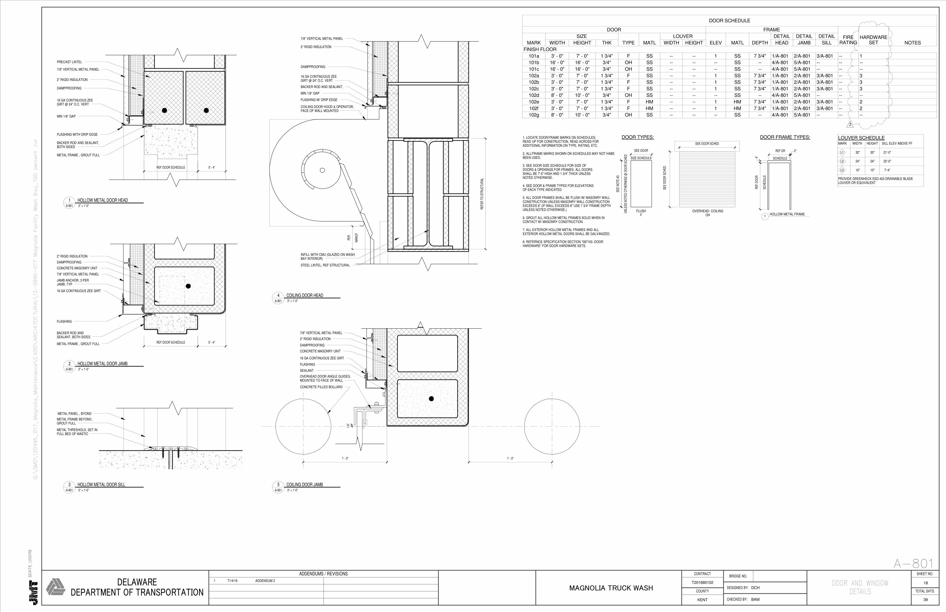
1. LOCATE DOOR/FRAME MARKS ON SCHEDULES;READ UP FOR CONSTRUCTION, READ ACROSS FORADDITIONAL INFORMATION ON TYPE, RATING, ETC.
2. ALL/FRAME MARKS SHOWN ON SCHEDULES MAY NOT HABEBEEN USED.
3. SEE DOOR SIZE SCHEDULE FOR SIZE OFDOORS & OPENINGS FOR FRAMES. ALL DOORSSHALL BE 7'-0" HIGH AND 1 3/4" THICK UNLESSNOTED OTHERWISE.
4. SEE DOOR & FRAME TYPES FOR ELEVATIONSOF EACH TYPE INDICATED.
5. ALL DOOR FRAMES SHALL BE FLUSH W/ MASONRY WALLCONSTRUCTION UNLESS MASONRY WALL CONSTRUCTIONEXCEEDS 8" (IF WALL EXCEEDS 8" USE 7 3/4" FRAME DEPTHUNLESS NOTED OTHERWISE.)
6. GROUT ALL HOLLOW METAL FRAMES SOLID WHEN INCONTACT W/ MASONRY CONSTRUCTION.
7. ALL EXTERIOR HOLLOW METAL FRAMES AND ALLEXTERIOR HOLLOW METAL DOORS SHALL BE GALVANIZED.
8. REFERNCE SPECIFICATION SECTION "087100 -DOORHARDWARE" FOR DOOR HARDWARE SETS.
FLUSHF
SIZE SCHEDULE
SEE DOOR
UN
LESS
NO
TED
OTH
ER
WIS
E @
DO
OR
SCH
ED
SEE
NO
TE #
3
DOOR FRAME TYPES:
SCHE
DU
LE
REF
DO
OR
SCHEDULE
REF DR 2"
4"
HOLLOW METAL FRAME
DOOR TYPES:
1
UN
LESS
NO
TED
OTH
ER
WIS
E @
DO
OR
SCH
ED
SEE
NO
TE #
3
SEE
DO
OR
SC
HED
SEE DOOR SCHED
OVERHEAD- COILINGOH
LOUVER SCHEDULEMARK
L1
WIDTH HEIGHT SILL ELEV ABOVE FF
32"
L2
L3
30" 21'-0"
24" 24" 22'-0"
10" 10" 7'-4"
PROVIDE GREENHECK ESD-403 DRAINABLE BLADELOUVER OR EQUIVALENT
BACKER ROD AND SEALANT,BOTH SIDES
REF DOOR SCHEDULE 0' - 4"
FLASHING WITH DRIP EDGE
DAMPPROOFING
PRECAST LINTEL
METAL FRAME , GROUT FULL
MIN 1/8" GAP
2" RIGID INSULATION
16 GA CONTINUOUS ZEEGIRT @ 24" O.C. VERT
7/8" VERTICAL METAL PANEL
BACKER ROD ANDSEALANT, BOTH SIDES
REF DOOR SCHEDULE 0' - 4"
FLASHING
DAMPPROOFING
CONCRETE MASONRY UNIT
METAL FRAME , GROUT FULL
JAMB ANCHOR, 3 PERJAMB, TYP
16 GA CONTINUOUS ZEE GIRT
7/8" VERTICAL METAL PANEL
2" RIGID INSULATION
METAL PANEL , BYOND
METAL THRESHOLD, SET INFULL BED OF MASTIC
METAL FRAME BEYOND ,GROUT FULL
BACKER ROD AND SEALANT,
COILING DOOR HOOD & OPERATOR,FACE OF WALL MOUNTED
2" RIGID INSULATION
DAMPPROOFING
16 GA CONTINUOUS ZEEGIRT @ 24" O.C. VERT
7/8" VERTICAL METAL PANEL
FLASHING W/ DRIP EDGE
MIN 1/8" GAP
MAN
UF
PER
REF
ER T
O S
TRU
CTU
RAL
INFILL WITH CMU (GLAZED ON WASHBAY INTERIOR)
STEEL LINTEL, REF STRUCTURAL
SEALANT
1/4"
OVERHEAD DOOR ANGLE GUIDES,MOUNTED TO FACE OF WALL
1' - 0"1' - 0"
CONCRETE FILLED BOLLARD
DAMPPROOFING
CONCRETE MASONRY UNIT
16 GA CONTINUOUS ZEE GIRT
7/8" VERTICAL METAL PANEL
2" RIGID INSULATION
FLASHING
ADDENDUMS / REVISIONS
DELAWAREDEPARTMENT OF TRANSPORTATION
KENT
T201680102
TOTAL SHTS.
SHEET NO.CONTRACT
COUNTYDESIGNED BY:
CHECKED BY:
BRIDGE NO.
MAGNOLIA TRUCK WASH
$D
AT
E_U
SE
R$
39
Q:\SMD\120995_017_Magnolia_Maintenance\CADD\ARCHITECTURAL\12-0995-017 Magnolia Facility Wash Bay_100 percent .rvt
DOOR AND WINDOW
DETAILSDCH
BAM
18
A-801
DOOR SCHEDULE
DOOR FRAME
FIRERATING
HARDWARESET NOTESMARK
SIZE
TYPE MATL
LOUVER
ELEV MATL DEPTH
DETAIL DETAIL DETAIL
WIDTH HEIGHT THK WIDTH HEIGHT HEAD JAMB SILL
FINISH FLOOR
101a 3' - 0" 7' - 0" 1 3/4" F SS -- -- 1 SS 7 3/4" 1/A-801 2/A-801 3/A-801 -- 1
101b 16' - 0" 16' - 0" 3/4" OH SS -- -- -- SS -- 4/A-801 5/A-801 -- -- --
101c 16' - 0" 16' - 0" 3/4" OH SS -- -- -- SS -- 4/A-801 5/A-801 -- -- --
102a 3' - 0" 7' - 0" 1 3/4" F SS -- -- 1 SS 7 3/4" 1/A-801 2/A-801 3/A-801 -- 3
102b 3' - 0" 7' - 0" 1 3/4" F SS -- -- 1 SS 7 3/4" 1/A-801 2/A-801 3/A-801 -- 3
102c 3' - 0" 7' - 0" 1 3/4" F SS -- -- 1 SS 7 3/4" 1/A-801 2/A-801 3/A-801 -- 3
102d 8' - 0" 10' - 0" 3/4" OH SS -- -- -- SS -- 4/A-801 5/A-801 -- -- --
102e 3' - 0" 7' - 0" 1 3/4" F HM -- -- 1 HM 7 3/4" 1/A-801 2/A-801 3/A-801 -- 2
102f 3' - 0" 7' - 0" 1 3/4" F HM -- -- 1 HM 7 3/4" 1/A-801 2/A-801 3/A-801 -- 2
102g 8' - 0" 10' - 0" 3/4" OH SS -- -- -- SS -- 4/A-801 5/A-801 -- -- --
3" = 1'-0"A-801
1 HOLLOW METAL DOOR HEAD
3" = 1'-0"A-801
2 HOLLOW METAL DOOR JAMB
3" = 1'-0"A-801
3 HOLLOW METAL DOOR SILL
3" = 1'-0"A-801
4 COILING DOOR HEAD
3" = 1'-0"A-801
5 COILING DOOR JAMB
1 7/14/16 ADDENDUM 2
2