Embed Size (px)
Citation preview

STATE OF ART
GRID TIE SOLAR
INVERTERS

INNOVATIVE
• Greater Energy Production. Maximizes the power conversion with highest efficiency. MPPT tracking up to 99.9%.
• Optimized Electric Control Technology with over 97.3 % efficiency. Lowest loss in industry.
ECONOMICAL
• Safe and clean aesthetics with IP 65 Protection for outdoor usage.
• ROI in less than 5 years.
RELIABLE
• Proven Reliability/long lasting.
• IEC Electrical and safety certification.
• More than 4.5 MW off and on grid system installed and running successfully.
CONVENIENT
• Greater Design flexibility with ease of operation.
• Large LCD Interface for visual and configuration.
Converting sunshine into savings and a greener planet
With a drastic fall in prices of SPV modules and Balance of System on one hand and the rising
electricity tariffs on the other, grid connected solar Roof Top PV systems are becoming increasingly
economically viable for the vast 1.3 billion population of India. The multiple benefits, expected
payback and mid-sized grid connected Roof Top PV solution offers a lot of economic benefit while
also complying with Government norms regarding the global carbon footprint.
The Grid Tie Solar Inverter / PV Grid Connected Inverter convert the direct current generated by the
solar module into grid-acceptable alternating current. Thus they form the heart of every solar
energy system. It is suited best for the tropical countries like India where the sunlight is in
abundance.
These new generation inverters are designed in single-phase from1.5 KW to 10 KW & three-phase
from10 KW to 1 MW systems.
PV GRID CONNECTED INVERTERS
FEATURES
Su-Kam Power Systems Ltd.Corporate Office: Plot No. 54, Udyog Vihar, Phase VI, Sector-37, Gurgaon -122001, Haryana, IndiaTel: +91-124-4170500 Fax: +91-124-4038700/1/2 E-mail: [email protected] Website: www.su-kam.com
24x7 call log in facility
Toll Free Helpline No.:
1800-102-4423
R

STATE OF ART
GRID TIE SOLAR
INVERTERS
RADIANT SERIES OF THREE PHASE INVERTERS 10 KWp-30 KWp-50KWp-100 KWp – 250 KWp – 500 KWp – 1000 KWp

High efficiency levels
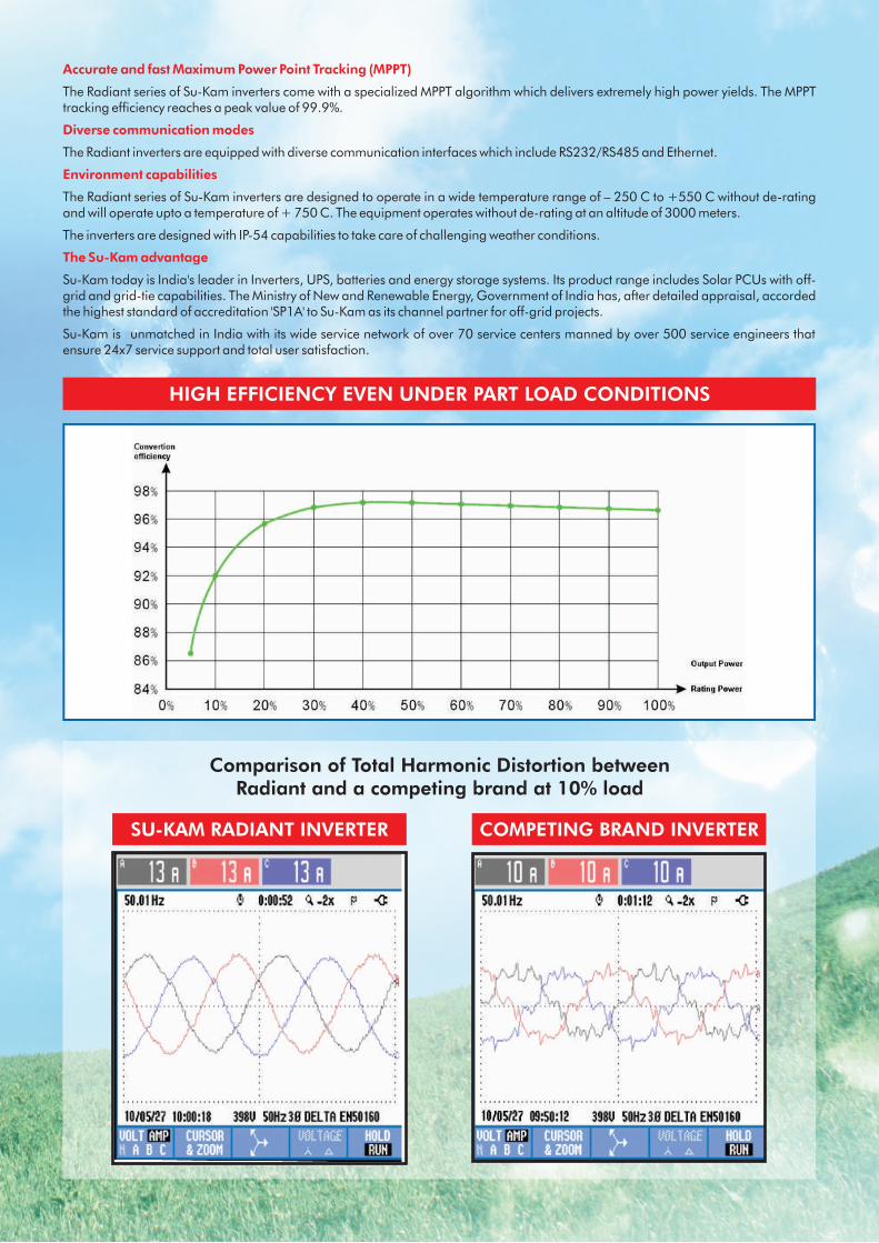
Employing highly efficient circuit topology, the Su-Kam Radiant series of three phase inverters deliver maximum power output with very high efficiency figures of 98.7%. Please see the efficiency curve for our 500 KW Radiant 500TL inverter.
Extremely low Total Harmonic Distortion (THD) - unmatched by the industry
The Su-Kam Radiant three phase inverters have achieved THD of 0.8% at 100% load and 3.7% at 10% load. Compare this with THD levels of 10% to 22% for some of the other leading brands. We have displayed the THD measurements recorded on an oscilloscope that compares our Radiant inverter with a competing brand inverter at 10% load.
The output of our inverter is a Pure Sine Wave compared with a relatively distorted wave form that some of the other inverters deliver. The customer, therefore, does not require a harmonic filter. At the grid connection point, a two winding transformer would serve the purpose against a three winding transformer which would be required to take care of harmonics.
The above features translate into lower risk of failure and lower total cost to the customer while ensuring that a high quality Sine Wave output is fed into the grid.
SALIENT FEATURES
Accurate and fast Maximum Power Point Tracking (MPPT)
The Radiant series of Su-Kam inverters come with a specialized MPPT algorithm which delivers extremely high power yields. The MPPT tracking efficiency reaches a peak value of 99.9%.
Diverse communication modes
The Radiant inverters are equipped with diverse communication interfaces which include RS232/RS485 and Ethernet.
Environment capabilities
The Radiant series of Su-Kam inverters are designed to operate in a wide temperature range of – 250 C to +550 C without de-rating and will operate upto a temperature of + 750 C. The equipment operates without de-rating at an altitude of 3000 meters.
The inverters are designed with IP-54 capabilities to take care of challenging weather conditions.
The Su-Kam advantage
Su-Kam today is India's leader in Inverters, UPS, batteries and energy storage systems. Its product range includes Solar PCUs with off-grid and grid-tie capabilities. The Ministry of New and Renewable Energy, Government of India has, after detailed appraisal, accorded the highest standard of accreditation 'SP1A' to Su-Kam as its channel partner for off-grid projects.
Su-Kam is unmatched in India with its wide service network of over 70 service centers manned by over 500 service engineers that ensure 24x7 service support and total user satisfaction.
HIGH EFFICIENCY EVEN UNDER PART LOAD CONDITIONS
Comparison of Total Harmonic Distortion betweenRadiant and a competing brand at 10% load
SU-KAM RADIANT INVERTER COMPETING BRAND INVERTER

-100 20 -8 41 4 : 2. 3o (N T oe lln i Fl rp el ee )H
Please contact us with your queries and our engineers will be happy to assist you with your requirement
Su-Kam Power Systems Ltd.
Corporate Office: Plot No. 54, Udyog Vihar, Phase VI, Sector-37, Gurgaon-122001, Haryana, India.E-mail: [email protected] Phone: +91-124-4170500, Fax: +91-124-4038700Website: www.su-kam.com Helpline No.:1800-102-4423
T E C H N I C A L P A R A M E T E R S
Input (D
C sid
e)
600X1000X
600 m
m800X1800X
650m
m900x2
000x
800 m
m1200/2
200
800 m
m1800/2
200/
800m
m1400/2
200/
800
mm
28
00
/220
0/
800m
m8
000/2
800/
22
00m
m100
00/2
800
/ 2200
mm
Para
mete
r at
DC
side
Max D
C V
olta
ge
880V D
C w
ith C
rystallin
e silico
n /7
20V D
C w
ith th
in film
Max D
C Po
wer
12 K
Wp
34 K
Wp
56 K
Wp
112 K
Wp
275 K
Wp
560
KW
P1
120
KW
p
Max In
paut
24
816
64
MM
PT R
ange
420V-8
50V
Max D
C in
put cu
rrent
50A
80A
130A
250A
600 A
1200A
2400
A
PV
Arra
y Config
ura
tion
Flo
atin
g N
egative
Gro
und Po
sitive G
round
Transfo
rmer
Ava
ilable
NA
Ava
ilable
NA
NA
Rate
d O
utp
ut Po
wer
10 K
W30KW
50 K
W100 K
W250KW
500
KW
10
00KW
Para
mete
r at
AC
side
Rate
d V
olta
ge
400V
27
0 V
27
0 V
10K
V/2
0K
V/3
5K
V
Volta
ge ra
nge
310V-4
50V
21
0 -3
10V
210 -3
10V
M.V
Transfo
rmer (o
ptio
nal)
Grid
Fre
quency
50H
z
Grid
Fre
quency R
ange
47-5
3H
z
TH
Di
<.8
%
Pf
>.9
9
Syste
mC
hara
cterstics
10
KW
p3
0KW
p5
0 K
Wp
100 K
Wp
250 K
WP
250 K
Wp T
L5
00 K
Wp T
L1
000 K
Wp T
L1
000 K
Wp
145( n
eed to
confirm
)M
axim
um
outp
ut
Curre
nt p
er P
hase
95.%
Max E
fficiency
95.3
%96.8
%97.2
%97.5
%98.3
%98.7
%98
.7%
97.8
%
94.3
%Euro
pia
n E
ff 94.5
%96.2
%96.6
%96.7
%97.7
%98.5
%98
.5%
97.4
%
MPPT A
ccura
cy99.9
%
Losse
s At n
ight
<10W
<15W
<20W
<40W
<100W
<10
0W
<15
00W
Sta
nby C
onsu
mptio
n<
100W
Am
bie
nt Te
mpera
ture
-25 to
55O
C w
ithout d
e-ra
ting
<1
50
W<
15
00W
Disp
lay a
nd
Com
munica
tion
Stora
ge Tem
pera
ture Ra
nge
-25 to
80O
C (N
eed to
Confirm
)
Rela
tive H
um
idity
95%
no co
ndensa
tion
Coolin
g M
eth
od
Air
Disp
lay
LCD
Com
munica
ton
Eth
ern
et/R
S232/R
S485
Am
bie
nt S
enso
rTe
mpera
ture
/ Sunlig
ht / W
ind S
peed
Dim
ensio
n (W
XH
XD
)
200
550
650
980
1960
980
1960
16
.7 T
19.5
TW
eig
ht (K
G)
<65 d
B(A
)N
oise
3000m
Max A
ltitude A
bove See level
Grid
(AC
side)
Faults D
ispla
yed o
n
Disp
lay
Arra
y Fail
AC
/DC
Earth
Fault
No S
ync
Frequency O
ut o
f Range
Inve
rter O
ver C
urre
nt
Ove
r volta
ge, u
nder vo
ltage, o
ver fre
quency, u
nder fre
quency, o
ver cu
rrent a
nd sh
ort circu
it, ove
r tem
pera
ture
, anti-isla
ndin
g, A
C e
arth
, fault.
Inve
rter O
ver Te
mp.
DC
Ove
r Volt.
Fast D
C o
ver V
olt.
Arra
y ove
r Volt.
DC
under V
olt.
Loca
l Em
erg
ency S
top (o
ptio
nal)
Wro
ng P
hase
Grid
abnorm
al
Outp
ut o
verlo
ad
Wound co
mponent
Arra
y reve
rse p
ola
rity (optio
nal)
Arra
y fuse
fail(o
ptio
nal)
Input (D
C sid
e)
Ove
r volta
ge a
nd u
nder vo
ltage
Prote
ctiveFu
nctio
n