Embed Size (px)
Citation preview
State Highway Database Operations Manual Effective Date: 20th
April 2014
Manual No.: SM050 Page i of viii
STATE HIGHWAY
DATABASE OPERATIONS MANUAL
Manual Number: SM050
Effective From: October 1996
Revised April 2014
NZ Transport Agency
44 Victoria Street
Private Bag 6995
WELLINGTON 6141
Telephone (04) 894 5400
Facsimile (04) 894 6100
Manual Owner: Information & Systems Manager
National Office Contact: Asset Information Manager
Regional Office Contact: Regional RAMM Champion
State Highway Database Operations Manual Effective Date: 20th
April 2014
Manual No.: SM050 Page ii of viii
ISBN 0-478-04721-5
NZ Transport Agency (formerly Transit New Zealand), October 1996, State Highway
Database Manual
Revised April 2014
State Highway Database Operations Manual Effective Date: 20th
April 2014
Manual No.: SM050 Page iii of viii
FOREWORD
The NZ Transport Agency (NZTA) is committed to operating state highway systems that
contribute to an integrated, safe, responsive and sustainable land transport system.
In order to achieve this objective, it is essential that the NZTA have a sound knowledge of the
state highway asset. Good knowledge and data enables reliable reporting of the current status
and condition of assets, as well as effective decision making on how the asset should be
managed in future.
The State Highway Database Operations Manual forms the main platform for the NZTA’s asset
data management. It provides the fundamental starting point, which will ensure that the above
reporting and decision-making will be relevant and appropriate.
This issue of the manual includes a number of changes since the previous version published in
August 2007. Apart from the usual ongoing software updates, the key changes include:
• Name changing from Transit New Zealand to the New Zealand Transport Agency
• Amendments to and the moving of the Communications Policy (formerly Appendix 7)
and Access Policy (formerly Appendix 8) to the main sections, now Sections 9 and 10
respectively.
• Appendix 9 (RAMM Forms) now becoming Appendix 7, due to the above.
• Various additions/deletions/amendments to:
o Appendix 1 Lookup Codes
o Appendix 3 Asset Register
o Appendix 4 Maintenance Activity Codes
o Appendix 5 Asset Information Annual Planner
The above changes represent a shift in the NZTA’s focus, to ensure we maintain information on
our whole asset and not just the pavement and surfacings. This will continue to be an area of
increasing concern for the NZTA. They also recognise the NZTA’s desire to improve data
quality and specifically to introduce an improved process of industry self-regulation.
General Manager, Network and Operations Group
State Highway Database Operations Manual Effective Date: 20th
April 2014
Manual No.: SM050 Page iv of viii
Manual Management Plan
State Highway Database
Operations Manual SM050
National Office Victoria Arcade
44 Victoria Street Private Bag 6995, WELLINGTON
Phone: +64 4 894 5400 Fax: +64 4 894 6100
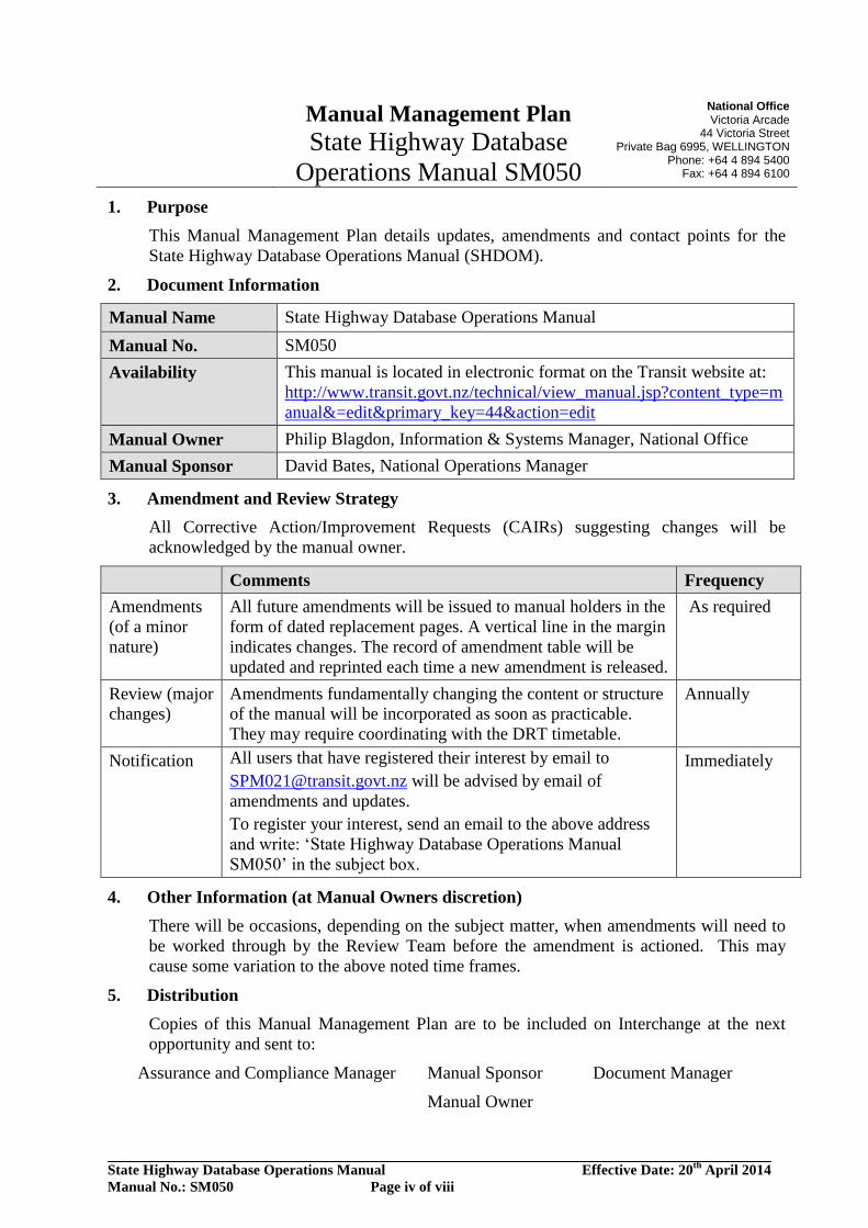
1. Purpose
This Manual Management Plan details updates, amendments and contact points for the
State Highway Database Operations Manual (SHDOM).
2. Document Information
Manual Name State Highway Database Operations Manual
Manual No. SM050
Availability This manual is located in electronic format on the Transit website at:
http://www.transit.govt.nz/technical/view_manual.jsp?content_type=m
anual&=edit&primary_key=44&action=edit
Manual Owner Philip Blagdon, Information & Systems Manager, National Office
Manual Sponsor David Bates, National Operations Manager
3. Amendment and Review Strategy
All Corrective Action/Improvement Requests (CAIRs) suggesting changes will be
acknowledged by the manual owner.
Comments Frequency
Amendments
(of a minor
nature)
All future amendments will be issued to manual holders in the
form of dated replacement pages. A vertical line in the margin
indicates changes. The record of amendment table will be
updated and reprinted each time a new amendment is released.
As required
Review (major
changes)
Amendments fundamentally changing the content or structure
of the manual will be incorporated as soon as practicable.
They may require coordinating with the DRT timetable.
Annually
Notification All users that have registered their interest by email to
[email protected] will be advised by email of
amendments and updates.
To register your interest, send an email to the above address
and write: ‘State Highway Database Operations Manual
SM050’ in the subject box.
Immediately
4. Other Information (at Manual Owners discretion)
There will be occasions, depending on the subject matter, when amendments will need to
be worked through by the Review Team before the amendment is actioned. This may
cause some variation to the above noted time frames.
5. Distribution
Copies of this Manual Management Plan are to be included on Interchange at the next
opportunity and sent to:
Assurance and Compliance Manager
Manual Sponsor
Manual Owner
Document Manager
State Highway Database Operations Manual Effective Date: 20th
April 2014
Manual No.: SM050 Page v of viii
DOCUMENT STATUS
This document has the status of a guideline as defined in NZ Transport Agency’s Standards and
Guidelines Manual available at:
http://www.transit.govt.nz/technical/manuals.jsp.
The objective of the manual is set out in NZTA’s policies and procedures for managing the state
highway network in a manner that meets NZTA’s goals.
The content is based on NZTA’s current practices and those developed in the past from
experience in managing the network.
While all care has been taken in compiling this document, the NZTA Board accepts no
responsibility for failure in any way related to the application of this guide or any reference
document noted in it. There is a need to apply judgement to each particular set of circumstances.
State Highway Database Operations Manual Effective Date: 20th
April 2014
Manual No.: SM050 Page vi of viii
RECORD OF AMENDMENTS
Amendment
No
Subject Effective
Date
Updated By
2
3
4
5
6
Revision
Re-issued – extensive rewrite
Re-issued – extensive rewrite
Foreword
General amendment
Document Status
Amendment to name of Guidelines Manual inc. web
address
Amendment procedures
Page deleted and incorporated into new Manual
Management Plan
Amendment List registration Form
Page deleted and incorporated into new Manual
Management Plan
Record of Amendments
Page revised and reworded
Sections 1 to 11 inc.
Minor amendments
Appendix 1
Minor additions/deletions to existing Look-up tables
Retaining walls and Street lighting tables added
Appendix 2
Minor amendments/rewording to Event Codes
Appendix 3
Minor additions/deletions (marked in red font) to existing
Asset Register
Retaining Wall table added
Street Light Pole table added
Street Light Bracket table added
Appendix 4
Minor additions/deletions to Maintenance Cost, Activity
and Fault Codes
Appendix 1 and 4
Additions and deletions as per memo TNZ TM8001
Appendix 5
2007 AIAP replaces 2006 version as per memo TNZ
TM8001
Jan 1998
Sept 2001
July 2004
08/03/06
03/01/07
R. Allen
R. Allen
State Highway Database Operations Manual Effective Date: 20th
April 2014
Manual No.: SM050 Page vii of viii
Amendment
No
Subject Effective
Date
Updated By
7
Various amendments to Sections 1 to 10 inc., dealing specifically
with the introduction to the accreditation certificate for RAMM
users, the hosting service being supplied by RAMM Software Ltd.
This includes:
Deletion of Section 5 – Maintenance Activities
Deletion of Section 6 – NOMAD
(Note: the main parts of the above 2 deleted sections have been
incorporated into the newly formed Section 4).
Deletion of Section 11 – Protocol for TNZ Regions 3 & 4
(RAMM2)
Appendix 1
Minor additions/deletions to existing Look-up tables
Shoulders tables added
Appendix 2
Minor amendments/rewording to Event Codes
Appendix 3
Minor additions/deletions (marked in red font) to existing
Asset Register
Pavement Test Pit table added
Street Light table added
Appendix 4
Minor additions/deletions to Maintenance Cost, Activity
and Fault Codes
Addition of Appendix 6 – Inventory Collection Manual
Addition of Appendix 7 – Communications Policy
Addition of Appendix 8 – Access Policy
Addition of Appendix 9 – RAMM Forms
01/08/07
R. Allen
8 Amendments to Appendix 6 Inventory as a result of industry
review workshops
Surfacings section for clarification of correct data
collection and updating, including examples
ITS section to reflect ITS table structure and collection
and maintenance of national ITS dataset.
Major update of Appendix 1 to align lookup codes with current
active lookups in RAMM, incorporating extensive new ITS
lookups.
Addition of Section 12 – Maintenance Activities
Amendments to Appendix 3
Minor additions/deletions (marked in red font) to existing
Asset Register
Amendments to Carriageway Surfacings to align with
RAMM 2011a database structure and specify mandatory
and conditional data requirements
1/1/2014 P Ball
S.Rainsford
M.Cousins
A. Bevins
State Highway Database Operations Manual Effective Date: 20th
April 2014
Manual No.: SM050 Page viii of viii
Amendment
No
Subject Effective
Date
Updated By
9 Amendments to Appendix 4 Maintenance Activity Codes to
include required units of measure and update current codes.
Please note the removal of multiple ‘UNKNOWN’ fault cost
group combination codes.
20/04/2014 P Ball
State Highway Database Operations Manual Effective Date: 20th
April 2014
Manual No.: SM050 Page ix of viii
TABLE OF CONTENTS
Section 1: Asset Information Management Overview
Section 2: Asset Register
Section 3: Road and Section Definitions
Section 4: Data Delivery Procedures
Section 5: Auditing Procedures
Section 6: Field Validation Procedures
Section 7: Traffic Data
Section 8: LTPP Site Maintenance Database
Section 9: Communications Policy
Section 10: Access Policy
Section 11: Intelligent Transportation Systems
Section 12: Maintenance Activities
Appendix 1: Lookup Codes
Appendix 2: Event Codes
Appendix 3: Asset Register
Appendix 4: Maintenance Activity Codes
Appendix 5: Asset Information Annual Planner
Appendix 6: Inventory Collection Manual
Appendix 7: RAMM Forms
Section 1: Asset Information Management Overview
State Highway Database Operations Manual Effective Date: 1st December 2008 Manual No.: SM050 Page 1-1
SECTION 1
ASSET INFORMATION MANAGEMENT OVERVIEW
1.0 Introduction
Background The NZ Transport Agency (NZTA), asset management information system is
designed as a decision support system for roading managers and practitioners to assist in providing a picture of the roading network condition. The asset management information system combines information from field surveys and office records to provide statistical data, road maintenance information, road maintenance priorities and estimates of maintenance costs.
In this Section The topics in this section are listed below:
Topic See Page Key Elements Purpose and Scope of Manual Overview of State Highway Asset Management Information System Computer Backups
1-2 1-3 1-4
1-6
Section 1: Asset Information Management Overview
State Highway Database Operations Manual Effective Date: 1st December 2008 Manual No.: SM050 Page 1-2
1.1 Key Elements
Elements The key elements of the core asset management information system:
• An Asset Register of the roading network, e.g lengths, widths,
pavement types, traffic counts, and also inventory items, • Condition Data, e.g. visual rating – number of potholes, scabbing,
cracking and high-speed data – roughness, texture, rutting, skid resistance, etc.
• Forward Works Programme, this is the 10-year future works programme for maintenance activities (NOMAD) carried out on the road network e.g. reseals, area-wide pavement treatments, maintenance strategies, etc.
• Reporting outputs. The reporting outputs provide useful information to roading management to support maintenance strategy decisions, programming and budgeting.
• Data collection & quality system. Information must be collected and managed in accordance with a robust quality assurance system.
Factors for success
The success of any management information system is dependent on the following factors: • Quality of data • Completeness of data • Usefulness of data • Timeliness of information delivery • Accuracy of location The focus of this manual is on the provision of quality and timely information. These two factors in turn contribute to the usefulness of the information the system provides.
References The current version of all standards, criteria or guidelines referred to in this
manual can be determined from NZTA’s Standards, Criteria and Guidelines Manual.
Section 1: Asset Information Management Overview
State Highway Database Operations Manual Effective Date: 1st December 2008 Manual No.: SM050 Page 1-3
1.2 Purpose and Scope of Manual
Purpose To provide a documented framework of operational procedures and activities
to ensure the consistency of good management of NZTA’s State Highway Asset Management Information System.
Scope The manual therefore provides:
• The administration and operational structure of NZTA’s State
Highway asset information system database. • Activities, responsibilities and reporting requirements. • Timetables, see Appendix 5 – Asset Information Annual Planner • Standard procedures and documentation for updating the database. This manual should be used in conjunction with the relevant software user manual from the respective software vendors. Asset systems not covered in this manual are: • State Highway Traffic Monitoring System (TMS) • State Highway Bridge Data System (BDS)
Quality assurance
The manual is a link in the quality assurance chain between consultants/ contractors, delegated authorities, NZTA Regional Offices and NZTA National Office.
The manual expects that all data provided by consultants and contractors complies in all respects with the quality assurance requirements for data collection of the specific contracts under which updating is required.
Section 1: Asset Information Management Overview
State Highway Database Operations Manual Effective Date: 1st December 2008 Manual No.: SM050 Page 1-4
1.3 Overview of State Highway Asset Management Information System
Introduction The national State Highway network asset management database is hosted by
CJN Technologies. The central computer is linked to personal computers at National Office and Regional Offices via the wide-area network. Access for NZTA staff is via the icon on their PC. Access for external suppliers will be through the CJN hosting service over the internet.
Password Access
Access to the asset management information system is restricted to authorised users with passwords. Refer to the Access Policy (section 10) of this manual for the correct procedure in obtaining access.
Database Integrity
To ensure database security and uniformity, access to the Road Names, Carriageway and most lookup Tables for adding and/or updating purposes is restricted to the SH Assets Team at National Office only.
System Administration Services
CJN Technologies provides system administration support services. These services include: • Database security including archiving and disaster recovery planning • Installing RAMM program upgrades • Server upgrades (both hardware & operating system)
Suppliers Environment
Consultants operate the hosted Asset Information System via remote access. NZTA wishes to maintain the integrity of its RAMM data. With suppliers having direct access to the NZTA master database, NZTA is concerned to ensure that only individuals with adequate skills and understanding will access and update data in the database. For this reason, NZTA is only going to allow access to users from outside organisations, who can demonstrate they are properly accredited.
Section 1: Asset Information Management Overview
State Highway Database Operations Manual Effective Date: 1st December 2008 Manual No.: SM050 Page 1-5
1.3 Overview of State Highway Asset Management Information System, continued
Supplier Accreditation for Database Access
Training for accredited RAMM users, is based on a ‘Train the Trainers’ approach. Trainers will be registered following completion of a course held by NZTA at a frequency (e.g. biannual) sufficient to maintain currency of database knowledge. It is intended that, on completion of the course, the trainer attendees will attain certification, which will enable them to carry out training of others to a level of certification sufficient to allow those trainees to have ‘write’ access to the NZTA RAMM database. Registration of Trainers and their trainees will be maintained by NZTA on an ongoing basis to manage access privileges to the NZTA RAMM database.
Read-only Inventory Collection
Write Access
No accreditation required
All inventory must be collected by personnel certified at level 1 competency
Write access by personnel certified to level 2 competency which assumes level 1 inventory collection
Note: Various levels of ‘write’ access are granted based on supplier responsibility in terms both of network coverage and also asset type.
Accreditation achieved at initial ‘train the trainers’ course.
Accreditation maintained by attendance at further NZTA ‘train the trainers’ course.
ACCREDITED TRAINERS

Section 1: Asset Information Management Overview
State Highway Database Operations Manual Effective Date: 1st December 2008 Manual No.: SM050 Page 1-6
1.4 Computer Backups
Responsibility CJN Technologies is responsible for ensuring backups are successful (the
following morning etc).
Special Requests
Requests for supplementary backups, special archiving and the restoration of data from backups should be directed to the Asset Database Administrator.
Section 2: Asset Register
State Highway Database Operations Manual Effective Date: 1st December 2008 Manual No.: SM050 Page 2-1
SECTION 2
ASSET REGISTER
2.0 Overview
Introduction The asset register is the record of the physical elements of the State Highway
System that were created, maintained, renewed or disposed of at NZ Transport Agency’s (NZTA) discretion and including: • Location of assets • The condition of these assets • The maintenance effort expended • The demand (traffic and loadings) the pavement asset is subjected to
Background NZTA’s Asset Register is contained in the Road Assessment and
Maintenance Management (RAMM) database. The initial effort in data collection to establish the RAMM database took place in the late 1980s – early 1990s. The focus at that time was on the pavement related asset components for the operation of the Treatment Selection Algorithm (TSA). Later extensions to the register included signs, street lighting, markings, railings, minor structures and features information. Some of these components have not been as well defined, or followed a nationally coordinated implementation, as the former pavement related components. Other assets e.g. bridges are recorded in other databases. Condition data from manual surveys has been collected since 1989, along with roughness data. The current database holds this annual data from 1992. Skid resistance data is held for surveys completed in 1995 & 1998 onwards. Maintenance activity (cost and quantity) relating to pavement works has been loaded into RAMM since 1999 and on some networks this data goes back to 1992.
In this Section The topics in this section are listed below:
Topic See Page Extent Applying the Asset Register Glossary of Terms used in Appendix 3, Asset Register
2-2 2-4 2-6
Section 2: Asset Register
State Highway Database Operations Manual Effective Date: 1st December 2008 Manual No.: SM050 Page 2-2
2.1 Extent
Functions The business functions that the asset register supports are:
• The Asset Management Plan • The National State Highway Strategy • Valuation of the State Highway Asset • Determination of Performance Measures • Inputs to Treatment Intelligence, e.g. dTIMS • Inputs to Contract Schedules • Operation Management
Goals The overall goals are:
• The asset register is complete • The asset location is maintained • Data collection methods are cost effective • Data collected is fit for purpose • The asset register is maintained to meet the annual planning
timeframe. It is accepted that there are asset types, which are missing from the national asset register. Areas that are currently being investigated by NZTA for future inclusion are: Traffic Islands, Intersections, Traffic Signals and Rest Areas.
Section 2: Asset Register
State Highway Database Operations Manual Effective Date: 1st December 2008 Manual No.: SM050 Page 2-3
2.1 Extent - continued
Elements Using the definition stated in the introduction, “a record of all physical
elements of a State Highway” this includes: • Carriageway, e.g. dimensional attributes of the highway • Carriageway surfacings • Drainage, e.g. culverts, flume, sumps, etc • Features (other important features not necessarily owned by the
Crown) • ITS Assets (will need to be added to Appendix 3 if inc.) • Lighting, e.g. bracket, model, pole, etc. • Minor Structures, e.g. underpasses, etc. • Pavement Layer, depth of granular basecourse, etc • Pavement Markings • Pavement Test Pits and their survey header • Railings, e.g. barriers & sight rails • Retaining Walls • Road names • Shoulders • Signs, e.g. Regulatory & Permanent Warning signs • Surface water channels, e.g. concrete kerb and channel There is also condition and traffic data that is managed and maintained by NZTA directly which this section does not cover.
Storage The Asset Register is stored in the RAMM software owned by CJN
Technologies. RAMM uses a large relational database management system called Informix. Each type of element (sign, surfacing, railing, etc) is represented by a table and related to the road names tables by road_id and individual elements are measured from the road origin in metres. Please refer to NZTA’s LRMS Manual, SM051 for further information on the state highway referencing system, which is fundamentally a reference post & displacement (i.e. linear) system.
Section 2: Asset Register
State Highway Database Operations Manual Effective Date: 1st December 2008 Manual No.: SM050 Page 2-4
2.2 Applying the Asset Register
Overview Applying the asset register is ensuring that the goals identified in 2.1, Extent
are achieved.
Extent of data capture
Each element is represented by a table such as sign, c_surface, railings, etc and has a number of fields that are used to describe the element. An example of this is the sign_type field in the sign table, this field identifies the particular type of sign e.g. slippery when wet. NZTA stores in RAMM the fields as defined in Appendix 3, Asset Register for each table. If other fields are required please contact the Asset Information Engineer, NZTA National Office prior to collecting the data for approval.
Section 2: Asset Register
State Highway Database Operations Manual Effective Date: 1st December 2008 Manual No.: SM050 Page 2-5
2.3 Glossary of Terms used in Appendix 3, Asset Register
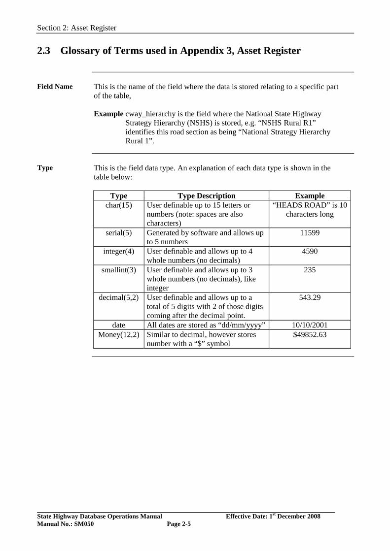
Field Name This is the name of the field where the data is stored relating to a specific part
of the table, Example cway_hierarchy is the field where the National State Highway
Strategy Hierarchy (NSHS) is stored, e.g. “NSHS Rural R1” identifies this road section as being “National Strategy Hierarchy Rural 1”.
Type This is the field data type. An explanation of each data type is shown in the
table below:
Type Type Description Example char(15) User definable up to 15 letters or
numbers (note: spaces are also characters)
“HEADS ROAD” is 10 characters long
serial(5) Generated by software and allows up to 5 numbers
11599
integer(4) User definable and allows up to 4 whole numbers (no decimals)
4590
smallint(3) User definable and allows up to 3 whole numbers (no decimals), like integer
235
decimal(5,2) User definable and allows up to a total of 5 digits with 2 of those digits coming after the decimal point.
543.29
date All dates are stored as “dd/mm/yyyy” 10/10/2001 Money(12,2) Similar to decimal, however stores
number with a “$” symbol $49852.63
Section 2: Asset Register
State Highway Database Operations Manual Effective Date: 1st December 2008 Manual No.: SM050 Page 2-6
2.3 Glossary of Terms used in Appendix 3, Asset Register - continued
Required by Software
States if required by the software. “Y” - Yes
Generated Value
The default value the software will insert unless altered by the user. “G” indicates that the software generates this field.
Required by NZTA
If “T”, this field is required by NZTA. If such data is not supplied then the deliverable will be rejected.
Description The description of the field.
Allowed Values This shows the lookup or the relevant table where the lookup is stored for
defined fields.
Not required There are a number of fields not required by NZTA. Although these fields are
not to be populated when delivering data to NZTA, a null or empty space is required to represent these empty fields. This is so that when loading the data electronically the software will easily load the data without NZTA having to manipulate the data. The delivery of data to NZTA is described in section 4, Data Delivery Procedures. For completeness all the fields have been supplied in Appendix 3, Asset Register.
Section 3: Road and Section Definitions
State Highway Database Operations Manual Effective Date: 1st December 2008 Manual No.: SM050 Page 3-1
SECTION 3
ROAD AND SECTION DEFINITIONS
3.0 Introduction
Overview State Highways are identified by a number, across Regional and Local
Authority boundaries, and in some instances are hundreds of kilometres long. It is necessary to break the network down into convenient lengths for management purposes; these are known as reference stations and carriageway sections.
Definition of a “road”
A Reference Station Length (RSL) has been chosen as a convenient length in most cases. Hence, for the purposes of NZ Transport Agency’s (NZTA) Asset Management System, each RSL will usually become a unique road, although divided highways, a one-way pair system, roundabouts and motorway ramps are also unique roads.
References State Highway Control Manual, Chapter 4 Section 1, specifies the distance
marking system to be maintained in accordance with the Location Referencing Management System Manual SM051. Refer to the Location Referencing Management System Manual SM051 for details regarding ramps referencing
In this Section The topics in this section are listed below:
Topic See Page Road Name Conventions Single Carriageway Divided Carriageways Common Highways Ramps Large Roundabouts Carriageway Sections Network Updating
3-2 3-4 3-6 3-9 3-11 3-14 3-17 3-19
Section 3: Road and Section Definitions
State Highway Database Operations Manual Effective Date: 1st December 2008 Manual No.: SM050 Page 3-2
3.1 Road Name Conventions
Overview A unique State Highway reference name is generated by NZTA’s LRMS, for each road in the database based on the information that is entered about that road.
Elements of the road name
The road name elements are described in the following example: Example: Road name 01N-0979/05.45-X985-R1-OFF
Element Description Required Example
State Highway Number Always 01N Reference Station number at the start of the RS length. Always 0979
Displacement of Established Route Position (if the road does not begin at a reference station)
When required 05.45
Station Type (i.e. RSL for Reference Station, RMP for ramp/interchange or RND for roundabout) Always RSL
Direction (if the road is a divided carriageway) When required I
Common State Highway number (if road is common with another state highway)
When required
Roundabout or interchange number. When required 985
Ramp number When required R1
Ramp Type (i.e. On or off) and Hierarchy When required OFF
Separators The elements are separated by the characters ‘-’ and ‘/’ and the identifier ‘C’
for common or “W” for roundabouts or “X” for interchanges. The program adds them when the name is generated. They are real characters in the concatenated name.
Section 3: Road and Section Definitions
State Highway Database Operations Manual Effective Date: 1st December 2008 Manual No.: SM050 Page 3-3
3.1 Road Name Conventions, continued
Example Below is an example of a completed road name screen for an On-Ramp in
Auckland, which joins SH22 at 0.53km:
Note that the “Alternate” name is the name given to the road under the LRMS Software package “Highways by Exor”.
Section 3: Road and Section Definitions
State Highway Database Operations Manual Effective Date: 1st December 2008 Manual No.: SM050 Page 3-4
3.2 Single Carriageway
Overview The simplest case is a single carriageway road, which requires basic data for
implementation.
Criteria Single carriageway sections typically start/end at Reference Stations. Some
single carriageway sections start/end at Established Route Positions and this could be the case where Local Authority Boundaries exist within the RS or they start or end at divided carriageway sections’ boundaries.
Data Requirements
The information required to generate a road name for a single carriageway is:
Element Description Required
State Highway Number Yes
Reference Station number at the start of the RS length. Yes
Displacement of Established Route Position (if the road does not begin at a reference station)
When required
Station Type RSL
Direction (if the road is a divided carriageway) No
Common State Highway number (if road is common with another state highway)
When required
Roundabout or interchange number. No
Ramp number No
Ramp Type (i.e. On or off) and Hierarchy No
Territorial Local Authority Yes
Regional Council Yes
Additional Fields
Additional fields such as Local Name, Suburb, Town are also available in the Road Name Table.
Section 3: Road and Section Definitions
State Highway Database Operations Manual Effective Date: 1st December 2008 Manual No.: SM050 Page 3-5
3.2 Single Carriageway, continued
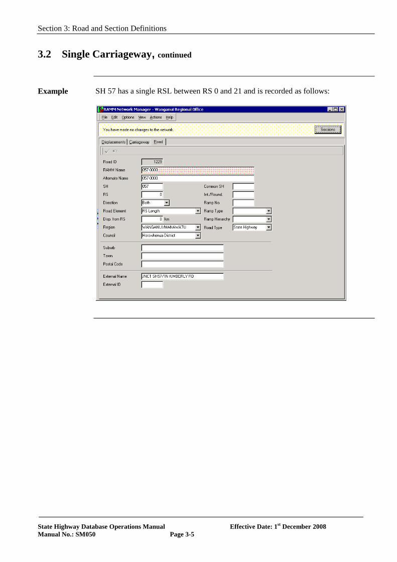
Example SH 57 has a single RSL between RS 0 and 21 and is recorded as follows:
Section 3: Road and Section Definitions
State Highway Database Operations Manual Effective Date: 1st December 2008 Manual No.: SM050 Page 3-6
3.3 Divided Carriageways
Overview Roads on each side of the median of a divided carriageway are given a unique
name (refer to section 2.5 of LRMS Manual).
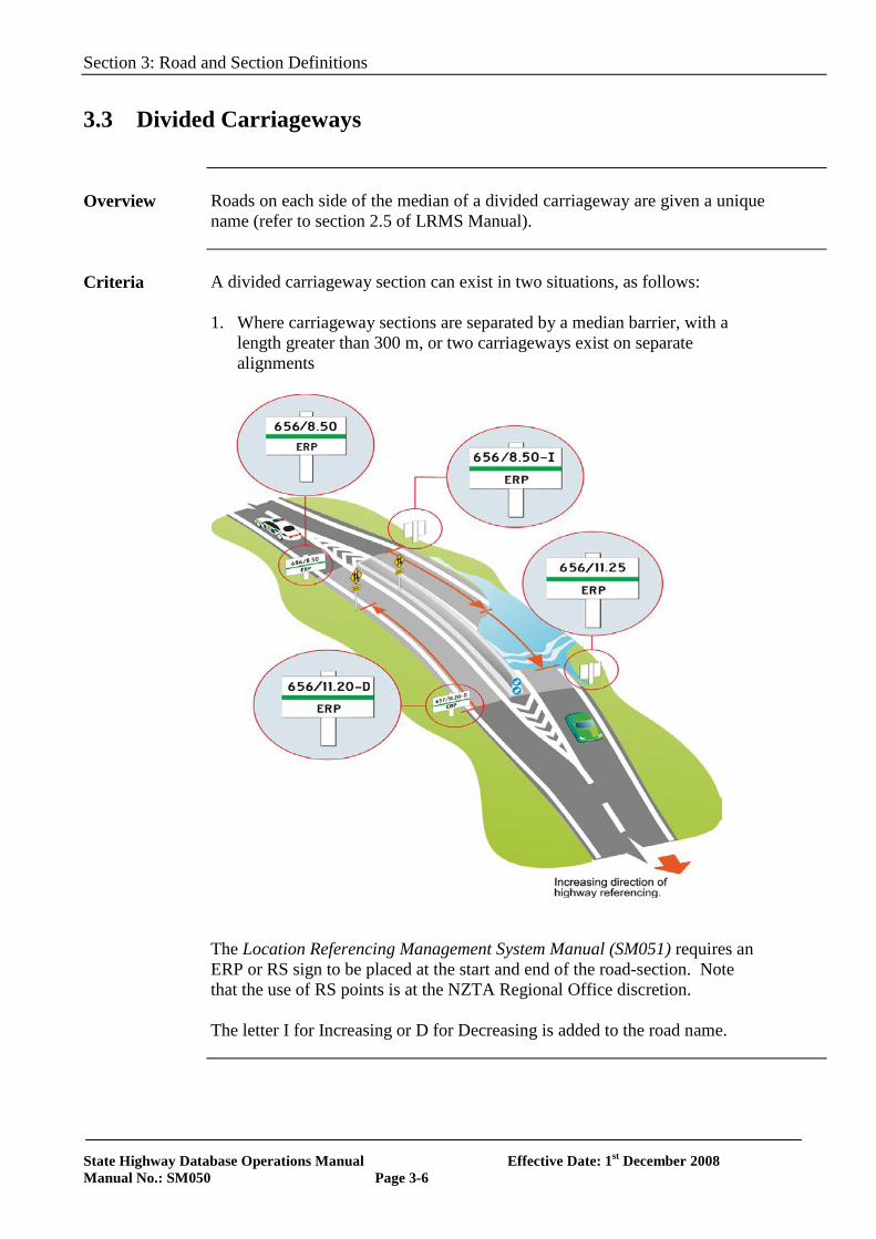
Criteria A divided carriageway section can exist in two situations, as follows:
1. Where carriageway sections are separated by a median barrier, with a
length greater than 300 m, or two carriageways exist on separate alignments
The Location Referencing Management System Manual (SM051) requires an ERP or RS sign to be placed at the start and end of the road-section. Note that the use of RS points is at the NZTA Regional Office discretion. The letter I for Increasing or D for Decreasing is added to the road name.
Section 3: Road and Section Definitions
State Highway Database Operations Manual Effective Date: 1st December 2008 Manual No.: SM050 Page 3-7
3.3 Divided Carriageways, continued
Medians at Intersections
A divided carriageway section can be implemented, if the distance between the start of the median on one side of the intersection and the end of the median on the other side of the intersection is greater than 300 m. Since a Reference Station is required at the intersection of two highways, the two sides are dealt with separately, i.e. the distance between the start and end of the median on each side of the intersection needs to be greater than 300 m.
Exception In any case where insufficient length means it is not required to give the
section a unique name, the divided or dual carriageway section could be recorded as a divided section, should there be a need to treat them as two separate roads. For example, a dual carriageway section, which is only 265 m in length, could be entered and named as a divided carriageway. This is at the Regional Office’s discretion.
Data Requirements
The information required to generate a road name for a divided carriageway is:
Element Description Required
State Highway Number Yes
Reference Station number at the start of the RS length. Yes
Displacement of Established Route Position (if the road does not begin at a reference station)
When required
Station Type RSL
Direction (if the road is a divided carriageway) Yes
Common State Highway number (if road is common with another state highway)
When required
Roundabout or interchange number. No
Ramp number No
Ramp Type (i.e. On or off) and Hierarchy No
Territorial Local Authority Yes
Regional Council Yes
Section 3: Road and Section Definitions
State Highway Database Operations Manual Effective Date: 1st December 2008 Manual No.: SM050 Page 3-8
3.3 Divided Carriageways, continued
Additional Fields
Additional fields such as Local Name, Suburb, Town are also available in the Road Name Table.
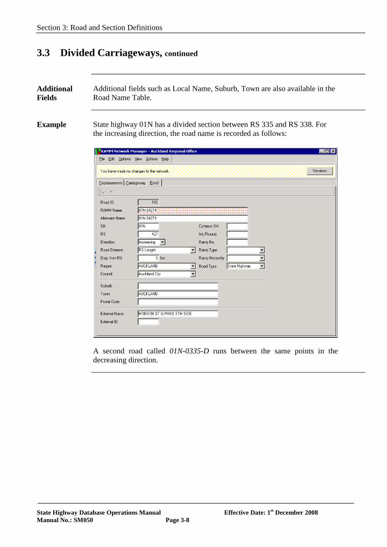
Example State highway 01N has a divided section between RS 335 and RS 338. For
the increasing direction, the road name is recorded as follows:
A second road called 01N-0335-D runs between the same points in the decreasing direction.
Section 3: Road and Section Definitions
State Highway Database Operations Manual Effective Date: 1st December 2008 Manual No.: SM050 Page 3-9
3.4 Common Highways
Overview To avoid double counting it is necessary to identify common routes.
Criteria Where two State Highways have a common route, RS are placed at the start
and end of the common length. All road asset information will be recorded against the lower numbered State Highway.
Data Requirements
The information required to generate a road name for a common highway is:
Element Description Required
State Highway Number Yes
Reference Station number at the start of the RS length. Yes
Displacement of Established Route Position (if the road does not begin at a reference station)
When required
Station Type RSL
Direction (if the road is a divided carriageway) When required
Common State Highway number (if road is common with another state highway) Yes
Roundabout or interchange number. No
Ramp number No
Ramp Type (i.e. On or off) and Hierarchy No
Territorial Local Authority Yes
Regional Council Yes
Additional Fields
Additional fields such as Local Name, Suburb, Town are also available in the Road Name Table.
Section 3: Road and Section Definitions
State Highway Database Operations Manual Effective Date: 1st December 2008 Manual No.: SM050 Page 3-10
3.4 Common Highways, continued
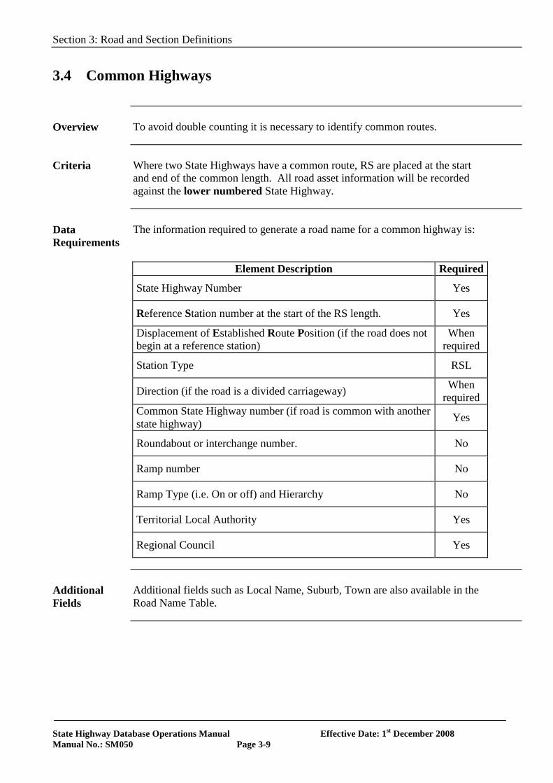
Example The road section on SH 3 between RS 445 and 450 has a common route with SH 01N between RS 845 and 850. For SH 01N the road is recorded as follows:
Section 3: Road and Section Definitions
State Highway Database Operations Manual Effective Date: 1st December 2008 Manual No.: SM050 Page 3-11
3.5 Ramps
Overview ON and OFF Ramps are components of the State Highway network, mostly
on motorways. Ramps can be of considerable length and are therefore recognised as unique roads. All On or Off Ramps connecting the highway are grouped and referenced to a unique interchange number. Ramps are generally numbered in a clockwise direction around the interchange, based on the location of the start of the ramp. Ramps are referenced as a separate road with positive displacements measured in the direction of traffic flow. Therefore, measurements on an on ramp will start at the RS on the boundary of the local road and end where it intersects with the highway. Note: Refer to Section 2.6 of the LRMS Manual for more details.
Criteria For an ON or OFF Ramp to qualify as an unique road, its length from
beginning to end will generally be greater than 100 metres and have a significant median barrier separating it from the main state highway. Note that the start of a ramp is where the full lane width starts, if an OFF ramp, or the maintenance boundary if an ON ramp.
Data Requirements
The information required to generate a road name for the ramp is:
Element Description Required
State Highway Number Yes Reference Station number at the start of the RS length. Yes Displacement where the ramp intersects the main SH Yes Station Type RMP Direction (if the road is a divided carriageway) When required Common State Highway number When required Roundabout or interchange number. Yes Ramp number Yes Ramp Type (i.e. On or off) and Hierarchy Yes Territorial Local Authority Yes Regional Council Yes
Section 3: Road and Section Definitions
State Highway Database Operations Manual Effective Date: 1st December 2008 Manual No.: SM050 Page 3-12
3.5 Ramps, continued
Additional Fields
Additional fields such as Local Name, Suburb, Town and Postal Code are also available in the Road Name Table.
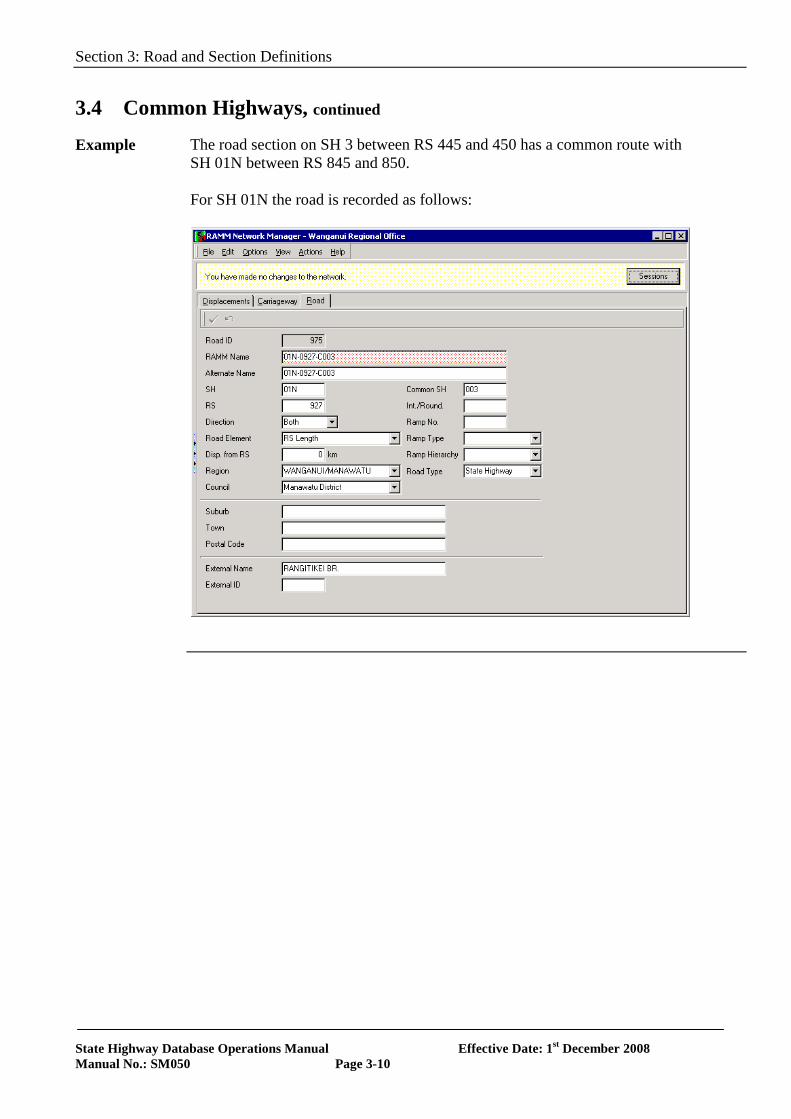
Example SH 02 has a ramp, which joins the state highway at 6.24 km from RS 164.
The road name is recorded as follows:
Complex Layouts
Refer to the Location Referencing Management System Manual SM051 for the numbering of ramps/interchanges at complex interchanges. A Reference Station Locality Diagram, showing traffic direction, state highway, named ramps and boundaries shall be forwarded to the Asset Information Engineer, Highways and Network Operations Group, NZTA National Office.
Section 3: Road and Section Definitions
State Highway Database Operations Manual Effective Date: 1st December 2008 Manual No.: SM050 Page 3-13
3.5 Ramps, continued
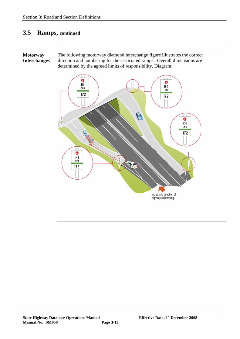
Motorway Interchanges
The following motorway diamond interchange figure illustrates the correct direction and numbering for the associated ramps. Overall dimensions are determined by the agreed limits of responsibility. Diagram:
Section 3: Road and Section Definitions
State Highway Database Operations Manual Effective Date: 1st December 2008 Manual No.: SM050 Page 3-14
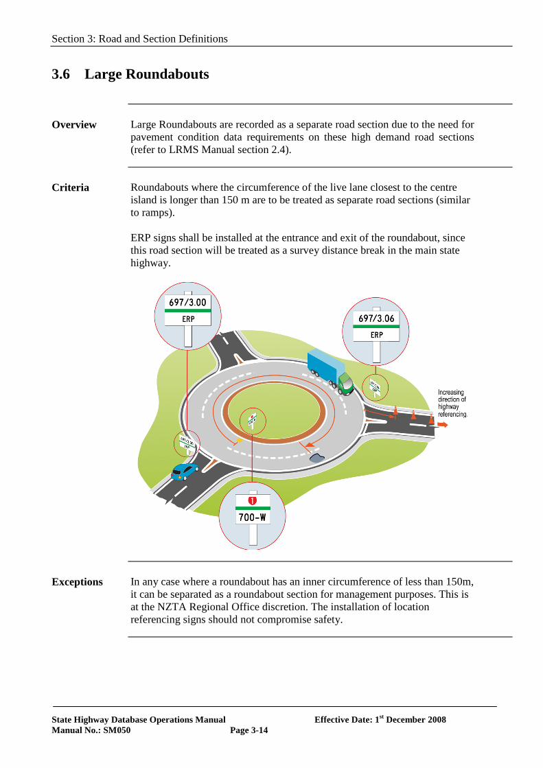
3.6 Large Roundabouts
Overview Large Roundabouts are recorded as a separate road section due to the need for
pavement condition data requirements on these high demand road sections (refer to LRMS Manual section 2.4).
Criteria Roundabouts where the circumference of the live lane closest to the centre
island is longer than 150 m are to be treated as separate road sections (similar to ramps). ERP signs shall be installed at the entrance and exit of the roundabout, since this road section will be treated as a survey distance break in the main state highway.
Exceptions In any case where a roundabout has an inner circumference of less than 150m,
it can be separated as a roundabout section for management purposes. This is at the NZTA Regional Office discretion. The installation of location referencing signs should not compromise safety.
Section 3: Road and Section Definitions
State Highway Database Operations Manual Effective Date: 1st December 2008 Manual No.: SM050 Page 3-15
3.6 Large Roundabouts, continued
Data Requirements
The information required to generate a road name for a roundabout is:
Element Description Required
State Highway Number Yes
Reference Station number at the start of the RS length. Yes
Displacement where the roundabout intersects the main state highway Yes
Station Type RND
Direction. This will always be “I” for increasing, where the roundabout lies on a divided highway
When required
Common State Highway number (if road is common with another state highway)
When required
Roundabout or interchange number. Yes
Ramp number No
Ramp Type (i.e. On or off) and Hierarchy No
Territorial Local Authority Yes
Regional Council Yes
Additional Fields
Additional fields such as Local Name, Suburb, Town and Postal Code are also available in the Road Name Table.
Section 3: Road and Section Definitions
State Highway Database Operations Manual Effective Date: 1st December 2008 Manual No.: SM050 Page 3-16
3.6 Large Roundabouts, continued
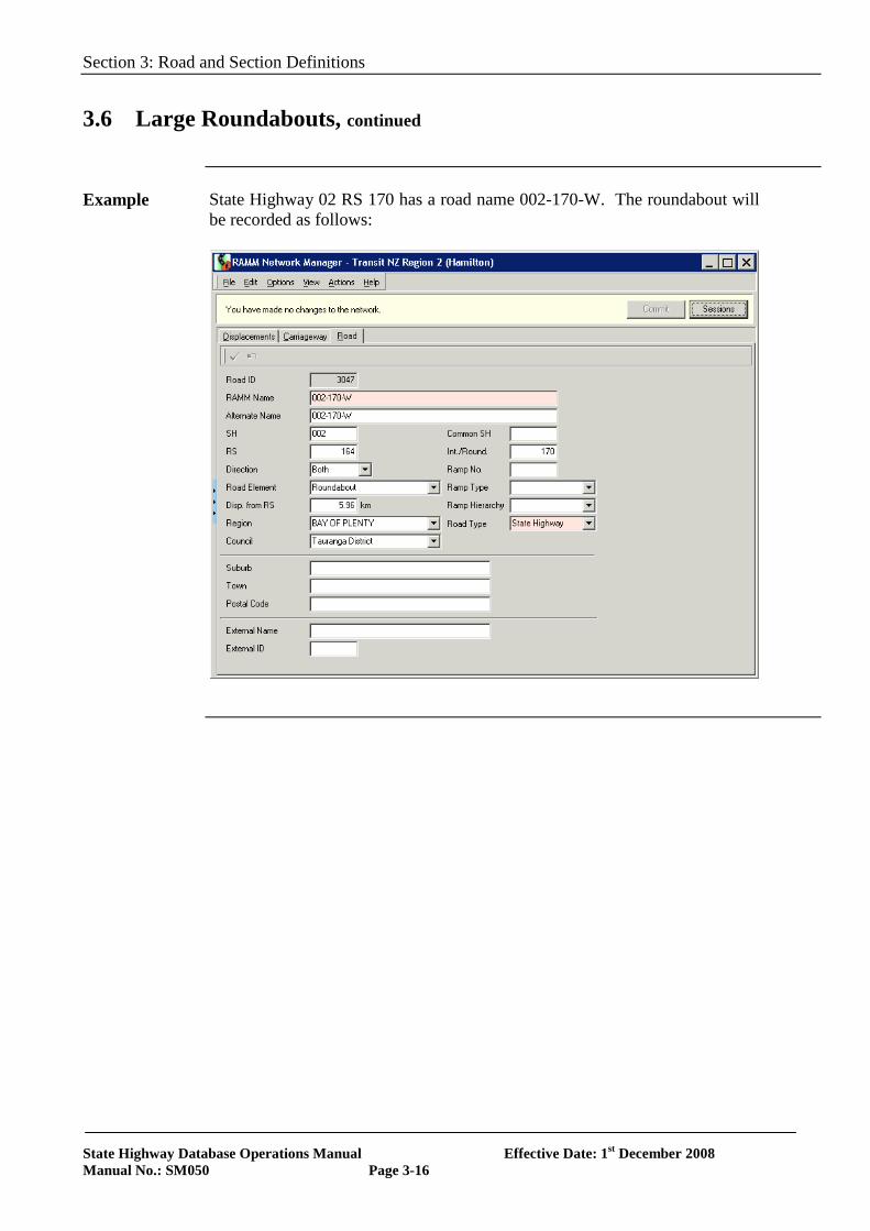
Example State Highway 02 RS 170 has a road name 002-170-W. The roundabout will
be recorded as follows:
Section 3: Road and Section Definitions
State Highway Database Operations Manual Effective Date: 1st December 2008 Manual No.: SM050 Page 3-17
3.7 Carriageway Sections
Overview Carriageways are the smallest divisions of the network. They are a
fundamental element of the NZTA’s asset management system. Changes to carriageway section displacements necessitate data manipulation in other tables by complex inventory updating, which can only be done by NZTA National Office, or data manipulation tools found in NZTA’s asset management system. Carriageway section changes are potentially hazardous to data integrity therefore only essential changes to carriageway sections should be contemplated. The original carriageway section concepts must be adhered to when updating.
Carriageway Sections
The following established guidelines apply when selecting carriageway sections:
• Change of pavement type, such as chipseal to structural asphalt concrete, sealed to unsealed, bridge (only bridges>50m in length).
• Significant change in traffic volumes including at nodes as defined by Traffic Monitoring System (TMS).
• Significant change in width, such as additional traffic lane or 2 m or more over a length of 100 m or more (approximately one lane width.)
• Change from rural to urban (<= 70kph), other changes in speed limit and policy changes in National State Highway Strategy (NSHS).
• Change to/from a legally-declared section of motorway.
Lengths of Sections
The longer the carriageway section the more averaging of dimensional data and other values will occur which may obscure various outputs. Conversely, very short carriageway sections (<50 m) are a nuisance value. It is difficult to comprehend the need for carriageway sections less than 50 m. The following guidelines should be applied:
• Urban carriageway sections, > 50m and < 500m • Rural carriageway sections, > 500m and < 5000m
Common State Highways
Carriageway sections of common State Highways are not duplicated. All inventory data (including carriageway data) is to be recorded against the lowest-numbered State Highway only. For example where SH 1N and SH 2 are common, the data is recorded for SH 1N only.
Section 3: Road and Section Definitions
State Highway Database Operations Manual Effective Date: 1st December 2008 Manual No.: SM050 Page 3-18
3.7 Carriageway Sections, continued
Passing Lanes The start of a passing lane should be taken as where the 2 lanes both become
full width and the end of the passing lane should be taken as where the centre line marking of the passing lanes finishes. Note: Care should be taken when road markings are replaced/repainted.
Urban Sections
In urban situations a block length is taken as a convenient carriageway section for compatibility with Local Authorities and urban maintenance strategies as shown below. Diagram:
SH A
SH A
WHI
TE R
OAD
BLAC
K RO
AD
KELL
Y GR
OVE
SH A
ROAD
SEC
TION
ROAD
SEC
TION
ROAD SECTIONROAD SECTIONROAD SECTION
GREEN STREET
Section 3: Road and Section Definitions
State Highway Database Operations Manual Effective Date: 1st December 2008 Manual No.: SM050 Page 3-19
3.7 Carriageway Sections, continued
Updating of Carriageway Sections
In April 2006, a comprehensive review of the rural road classifications was undertaken. This review, which was some 3 years after the previous one, found approximately 18% of the classifications incorrectly classified. These changes were implemented in RAMM in September 2006 after further consultation with NZTA’s Regional Offices. A process has now been established for annual updating of road classifications and June 30th as the date for all these changes to be implemented in RAMM. The Data Analyst at NZTA National Office will conduct these changes. To this aim it is important that the carriageway sections are checked and amended due to the above and also to the guidelines mentioned in ‘Road sections’ on page 3-17.
Network Updates
The need to maintain an accurate and up to date network is vital to NZTA’s business.
Primary Information
It is NZTA’s objective to update the base network model for new alignments within 10 days of these being open to traffic. NZTA National Office implements network changes, and asset data cannot be added until the network change has been completed. To achieve this timeframe the following minimum must be provided on a Network Update Form to the NZTA regional office for approval:
1. A clear diagram of the network before and after the network change 2. The start points and end points* of any new construction 3. The new measured lengths of any reference station lengths, which
have changed, and the new measured lengths of any roads, which have changed.
*To avoid data loss it is important that only sections following an entirely new alignment or which have been totally reconstructed are marked for deletion. The start and end of construction should therefore be identified using both the original and new route positions. Refer to the Network Update Form in the LRMS Manual for more detail.
Section 3: Road and Section Definitions
State Highway Database Operations Manual Effective Date: 1st December 2008 Manual No.: SM050 Page 3-20
3.7 Carriageway Sections, continued
Secondary Information
At the same time, or within 8 weeks of the opening of the above minimum, NZTA requires the following data:
4. New RS diagrams with measured geographic coordinates 5. A spatial representation of the centreline of the new alignment
NOTE: Prior to the start of the High Speed Data (HSD) survey for each Network Management Area, (the programme for which is available on the NZTA website), ALL items 1 to 4 inclusive needs to be collected at least 1 month earlier.
Section 4: Data Delivery Procedures
State Highway Database Operations Manual Effective Date: 1st December 2008 Manual No.: SM050 Page 4-1
SECTION 4
DATA DELIVERY PROCEDURES
4.0 Introduction
Introduction This section details the process of delivering RAMM data to NZ Transport
Agency’s (NZTA) Master RAMM database.
References Location Reference Management System Manual, SM051 (LRMS)
The SHDOM manual is to be used in association with the SM051. The SM051 details the requirements of the current location referencing system and includes the following forms:
• Network Update Form • Reference Station Locality Diagram • Route Position Nomenclature • Location reference sign schedule example • Log of Electronic Tripmeter Calibration • Spatial data specification
In this plan This plan covers the following topics.
Topic See Page NZTA’s Quality Process General Requirements Field Data Suppliers RAMM Managers Responsibilities Regional Office Responsibilities National Office Responsibilities Activity Reporting Milestone Activity Reporting
4-2 4-3 4-4 4-4 4-5 4-6 4-7 4-8
Section 4: Data Delivery Procedures
State Highway Database Operations Manual Effective Date: 1st December 2008 Manual No.: SM050 Page 4-2
4.1 NZTA’s Quality Process
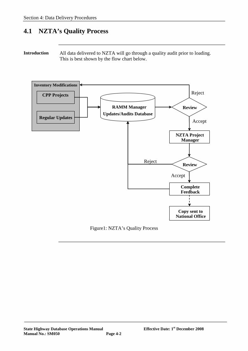
Introduction All data delivered to NZTA will go through a quality audit prior to loading.
This is best shown by the flow chart below.
Figure1: NZTA’s Quality Process
CPP Projects
Regular Updates
NZTA Project Manager
Review
Complete Feedback
Inventory Modifications
Reject
Accept
Review
Accept
RAMM Manager Updates/Audits Database
Copy sent to National Office
Reject
Section 4: Data Delivery Procedures
State Highway Database Operations Manual Effective Date: 1st December 2008 Manual No.: SM050 Page 4-3
4.1 NZTA’s Quality Process, continued
Glossary RAMM Manager
The RAMM Manager is usually the Network Management Consultant (NMC), however, in areas that are managed under a PSMC contract the PSMC contractor is to be taken as the RAMM Manager. NZTA Project Manager The NZTA project manager for the state highway asset maintenance, also known as the Area Engineer, whose responsibility is to manage the consultant as defined above (either the NMC, or PSMC contractor). RAMM Champion Asset Database Administrator Asset Information Engineer
Section 4: Data Delivery Procedures
State Highway Database Operations Manual Effective Date: 1st December 2008 Manual No.: SM050 Page 4-4
4.2 General Requirements
Introduction This section discusses requirements that affect all parties involved in the
collection and maintenance of asset information data, including:
• NZTA Staff, those at a regional and/or national role involved in asset information quality
• RAMM Manager, responsible for updating and auditing the database • Field Data Suppliers of asset information collected in the field.
Quality Assurance
NZTA requires all suppliers working on the state highway network to have an internal Quality Assurance (QA) system. This QA system must involve a process to handle non-conformances with corrective actions.
Certification NZTA has introduced a two tier certification requirement for individuals
involved with the collection of asset information data and the updating of the NZTA master database, these being: Level 1 – Field Data Collection All individuals that collect data in the field are required to have been certified to this level. Level 2 – Database Updating All individuals that add/update or delete data to the NZTA master database must be certified to Level 2. As a prerequisite for being certified to Level 2 the individual must be certified to Level 1 – Field Data Collection. These certification levels are required on all new contracts as of 1st July 2007 and all existing contracts by 30th June 2009.
Section 4: Data Delivery Procedures
State Highway Database Operations Manual Effective Date: 1st December 2008 Manual No.: SM050 Page 4-5
4.3 Field Data Suppliers
Introduction The collection of quality data in the field by suppliers is critical to the overall
value of an asset information system, ‘garbage in garbage out’.
Certification All individuals that collect data in the field are required to have been certified
to Level 1 – Field Data Collection. Note: It is possible for collectors of specialised data (e.g. Signs contractors) to be certified to collect only their ‘specialised’ type of data.
4.4 RAMM Managers Responsibilities
Introduction Confidence in the data accuracy being delivered is important. The outputs
from the Asset Register (currently stored in RAMM) are used in the development of Asset Management Plans, Asset Valuation, Contract Schedules, etc. The most efficient method of ensuring quality data is through a Quality Assurance (QA) system during data delivery.
Certification Data Collection and Auditing
RAMM Managers are required to collect and audit data collected in the field, and to update the NZTA RAMM database. It is therefore, required that staff that collect and audit field data are certified to Level 1 – Field Data collection. Database Updating Staff that update the NZTA RAMM Database are required to be certified to Level 2 – Database Updating (which requires Level 1 – Field Data Collection as a prerequisite).
Responsibilities RAMM Managers are required to collect, update and audit data on behalf of
NZTA and as in accordance with the Asset Information Annual Planner (AIAP) in Appendix 5. This involves: • Ensuring NZTA standards are met (see section 5, Auditing Procedures) • Receiving inventory information, maintenance activity and RAMM visual
condition rating data as necessary • Carry out audits on data captured in the field • Updating the NZTA master database based on changes to the network.
Section 4: Data Delivery Procedures
State Highway Database Operations Manual Effective Date: 1st December 2008 Manual No.: SM050 Page 4-6
4.5 Regional Office Responsibilities
Introduction NZTA’s Regional Offices project manage the network management contracts
& capital works projects.
Quality Assurance
It is responsibility of the NZTA Area Engineer to ensure that the following data are delivered in accordance with the Asset Information Annual Planner (AIAP) and that the documentation is correct. This includes deliverables associated to the following: • Inventory Updates • Visual Condition Rating • Forward Works Programme • Maintenance Activities
Certification All NZTA RAMM Champions and additional staff that are involved in the
collection and auditing of asset information data must be certified to Level 2 – Database Updating.
Audits The Project Manager shall undertake audits of the consultant, deliverables
prior to loading, this can either be an independent party or internally.
Acceptance of data
The project manager is required to ensure that the deliverables are complete and correct prior to either loading into RAMM by regional office staff or prior to the data deliverable forms being completed. At which time they send copies to the RAMM Database Administrator at National Office and a copy returned to the RAMM Manager.
Additional Responsibilities
Additional to the responsibilities identified above the Regional Offices are responsible for: • Management of the Traffic & Loading tables.
Section 4: Data Delivery Procedures
State Highway Database Operations Manual Effective Date: 1st December 2008 Manual No.: SM050 Page 4-7
4.6 National Office Responsibilities
Role In the area of data delivery National Office provide technical support to the
regional offices. National office manages the bulk loading of: • Traffic data National Office maintains the following tables: • Road names • Carriageway • Lookup codes • High-speed data (roughness, rutting, texture, geometry, etc.) • SCRIM • Falling Weight Deflectometer • CAS data National Office also maintains the network model (LRMS system) held within RAMM.
Responsibility National Office staff will review documentation and may carry out audit
checks as required and provide feedback to the Regional Office.
Section 4: Data Delivery Procedures
State Highway Database Operations Manual Effective Date: 1st December 2008 Manual No.: SM050 Page 4-8
4.7 Activity Reporting
Overview In 2007 a significant change to the loading and maintenance of the NZTA
RAMM Database transferred from NZTA National Office to the RAMM Manager. As such the historical batch delivery method of data delivery is being replaced by reporting on the level of activity. There are two types of activity reporting:
• Monthly Activity Report • Milestone Activity Report
Monthly Activity Report
RAMM Managers are required to provide a Monthly Activity report on the activity carried out for the month, this to be carried out on the Asset Data Activity Form and provide comments that maybe of interest including an explanation where there is no update due to ‘no activity’. These reports should be delivered by the dates shown on the Asset Information Annual Planner (AIAP) in Appendix 5 of this manual. Please refer to the Asset Information Engineer for any further clarification.
Milestone Activity Report
The Milestone Activity Report is to provide documentation that the database is up to date at key times in the year. The periods ending:
• 31st December • 31st March • 30th June
and should be delivered by the dates shown on the Asset Information Annual Planner (AIAP) in Appendix 5 of this manual. Please refer to the Asset Information Engineer for any further clarification. The Milestone Activity Report will include the following components:
• Asset Data Producer Statement • Asset Data Activity Form • Pavement and Surfacing Reconciliation Form • Maintenance Activity Form
Section 4: Data Delivery Procedures
State Highway Database Operations Manual Effective Date: 1st December 2008 Manual No.: SM050 Page 4-9
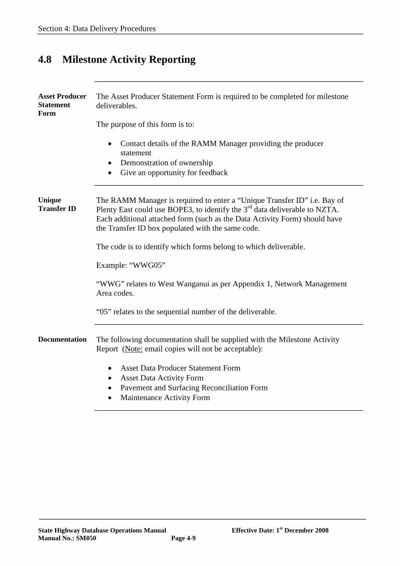
4.8 Milestone Activity Reporting
Asset Producer Statement Form
The Asset Producer Statement Form is required to be completed for milestone deliverables. The purpose of this form is to:
• Contact details of the RAMM Manager providing the producer statement
• Demonstration of ownership • Give an opportunity for feedback
Unique Transfer ID
The RAMM Manager is required to enter a “Unique Transfer ID” i.e. Bay of Plenty East could use BOPE3, to identify the 3rd data deliverable to NZTA. Each additional attached form (such as the Data Activity Form) should have the Transfer ID box populated with the same code. The code is to identify which forms belong to which deliverable. Example: “WWG05” “WWG” relates to West Wanganui as per Appendix 1, Network Management Area codes. “05” relates to the sequential number of the deliverable.
Documentation The following documentation shall be supplied with the Milestone Activity
Report (Note: email copies will not be acceptable):
• Asset Data Producer Statement Form • Asset Data Activity Form • Pavement and Surfacing Reconciliation Form • Maintenance Activity Form
Section 4: Data Delivery Procedures
State Highway Database Operations Manual Effective Date: 1st December 2008 Manual No.: SM050 Page 4-10
4.8 Milestone Activity Reporting, continued
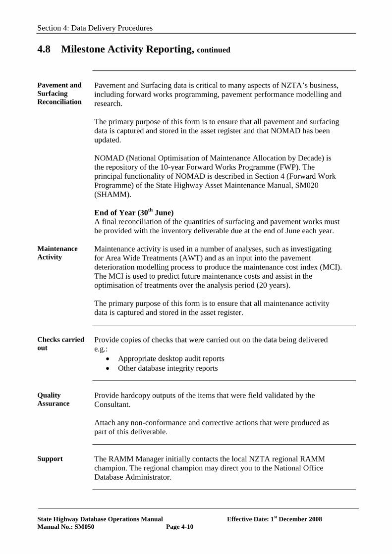
Pavement and Surfacing Reconciliation
Pavement and Surfacing data is critical to many aspects of NZTA’s business, including forward works programming, pavement performance modelling and research. The primary purpose of this form is to ensure that all pavement and surfacing data is captured and stored in the asset register and that NOMAD has been updated. NOMAD (National Optimisation of Maintenance Allocation by Decade) is the repository of the 10-year Forward Works Programme (FWP). The principal functionality of NOMAD is described in Section 4 (Forward Work Programme) of the State Highway Asset Maintenance Manual, SM020 (SHAMM). End of Year (30th June) A final reconciliation of the quantities of surfacing and pavement works must be provided with the inventory deliverable due at the end of June each year.
Maintenance Activity
Maintenance activity is used in a number of analyses, such as investigating for Area Wide Treatments (AWT) and as an input into the pavement deterioration modelling process to produce the maintenance cost index (MCI). The MCI is used to predict future maintenance costs and assist in the optimisation of treatments over the analysis period (20 years). The primary purpose of this form is to ensure that all maintenance activity data is captured and stored in the asset register.
Checks carried out
Provide copies of checks that were carried out on the data being delivered e.g.:
• Appropriate desktop audit reports • Other database integrity reports
Quality Assurance
Provide hardcopy outputs of the items that were field validated by the Consultant. Attach any non-conformance and corrective actions that were produced as part of this deliverable.
Support The RAMM Manager initially contacts the local NZTA regional RAMM
champion. The regional champion may direct you to the National Office Database Administrator.
Section 4: Data Delivery Procedures
State Highway Database Operations Manual Effective Date: 1st December 2008 Manual No.: SM050 Page 4-11
4.8 Milestone Activity Reporting, continued
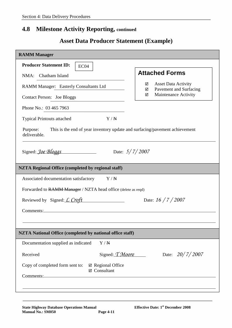
Asset Data Producer Statement (Example) Consultant Producer Statement ID: NMA: Chatham Island RAMM Manager: Easterly Consultants Ltd Contact Person: Joe Bloggs Phone No.: 03 465 7963 Typical Printouts attached Y / N Purpose: This is the end of year inventory update and surfacing/pavement achievement deliverable. Signed: Joe Bloggs Date: 5/ 7/ 2007 Associated documentation satisfactory Y / N Forwarded to RAMM Manager / NZTA head office (delete as reqd) Reviewed by Signed: L Croft Date: 16 / 7 / 2007 Comments: Documentation supplied as indicated Y / N Received Signed: T Moore Date: 20/ 7/ 2007 Copy of completed form sent to: Regional Office
Consultant Comments:
Attached Forms Asset Data Activity Pavement and Surfacing Maintenance Activity
EC04
RAMM Manager
NZTA Regional Office (completed by regional staff)
NZTA National Office (completed by national office staff)
Section 4: Data Delivery Procedures
State Highway Database Operations Manual Effective Date: 1st December 2008 Manual No.: SM050 Page 4-12
4.8 Milestone Activity Reporting, continued
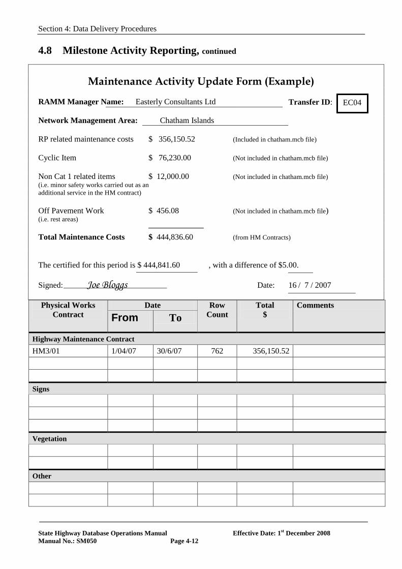
Maintenance Activity Update Form (Example)
RAMM Manager Name: Easterly Consultants Ltd Network Management Area: Chatham Islands RP related maintenance costs $ 356,150.52 (Included in chatham.mcb file) Cyclic Item $ 76,230.00 (Not included in chatham.mcb file) Non Cat 1 related items $ 12,000.00 (Not included in chatham.mcb file) (i.e. minor safety works carried out as an additional service in the HM contract) Off Pavement Work $ 456.08 (Not included in chatham.mcb file) (i.e. rest areas) Total Maintenance Costs $ 444,836.60 (from HM Contracts) The certified for this period is $ 444,841.60 , with a difference of $5.00. Signed: Joe Bloggs Date: 16 / 7 / 2007 Physical Works
Contract Date Row
Count Total
$ Comments
From To
Highway Maintenance Contract HM3/01 1/04/07 30/6/07 762 356,150.52 Signs Vegetation Other
Transfer ID: EC04
Section 4: Data Delivery Procedures
State Highway Database Operations Manual Effective Date: 1st December 2008 Manual No.: SM050 Page 4-12
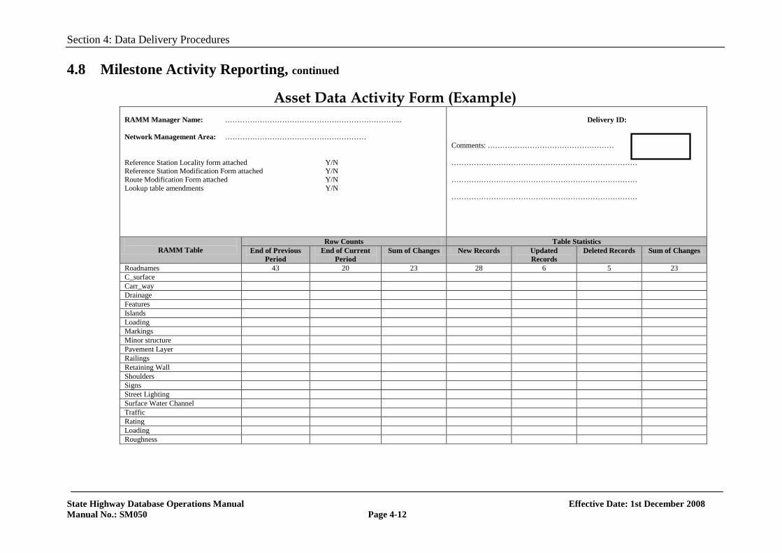
4.8 Milestone Activity Reporting, continued
Asset Data Activity Form (Example) RAMM Manager Name: ……………………………………………………………... Network Management Area: ………………………………………………… Reference Station Locality form attached Y/N Reference Station Modification Form attached Y/N Route Modification Form attached Y/N Lookup table amendments Y/N
Delivery ID: Comments: …………………………………………… ………………………………………………………………… ………………………………………………………………… …………………………………………………………………
RAMM Table
Row Counts Table Statistics End of Previous
Period End of Current
Period Sum of Changes New Records Updated
Records Deleted Records Sum of Changes
Roadnames 43 20 23 28 6 5 23 C_surface Carr_way Drainage Features Islands Loading Markings Minor structure Pavement Layer Railings Retaining Wall Shoulders Signs Street Lighting Surface Water Channel Traffic Rating Loading Roughness
Section 4: Data Delivery Procedures
State Highway Database Operations Manual Effective Date: 1st December 2008 Manual No.: SM050 Page 4-13
4.8 Milestone Activity Reporting, continued
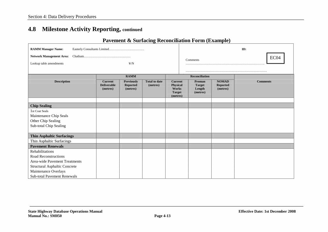
Pavement & Surfacing Reconciliation Form (Example)
RAMM Reconciliation Description Current
Deliverable (metres)
Previously Reported (metres)
Total to date (metres)
Current Physical Works Target
(metres)
Proman Target Length
(metres)
NOMAD Reported (metres)
Comments
Chip Sealing 1st Coat Seals Maintenance Chip Seals Other Chip Sealing Sub-total Chip Sealing Thin Asphaltic Surfacings Thin Asphaltic Surfacings Pavement Renewals Rehabilitations Road Reconstructions Area-wide Pavement Treatments Structural Asphaltic Concrete Maintenance Overlays Sub-total Pavement Renewals
RAMM Manager Name: Easterly Consultants Limited……………………………. Network Management Area: Chatham……………………………………… Lookup table amendments Y/N
ID: Comments …………………………………………………………………. ……………………………………………………………………
EC04
Section 5: Auditing Procedures
State Highway Database Operations Manual Effective Date: 1st December 2008 Manual No.: SM050 Page 5-1
SECTION 5
AUDITING PROCEDURES
5.0 Introduction
Background The accuracy and completeness of all tables in the Asset Register is
vital to NZ Transport Agency (NZTA) for the following key functions: • An accurate reliable inventory and valuation of the roading asset can
be obtained • Reliable reporting at the network or project level • Credible treatment length summaries and the production of multi-year
forward works programmes based on the Asset Register • Statistical comparisons between the regions can be made where
databases are consistent and accurate data is provided • Credibility of the asset information system is important for end users • Enable accurate inputs for contracts that rely on this data during the
tendering and performance monitoring processes.
Timing A desktop validation should be carried out 8 months prior to the completion
of an existing network management/PSMC contract. This is to allow tenders for the upcoming contract to be made aware of any possible issues. A follow-up desktop validation should be carried out in Year 2 of an NMC/PSMC contract. This is to measure the impact of the NMC to correct any issues identified in the pre-tender validation and identify areas for improvement prior to the completion of the contract.
In this Section The topics in this section are listed below:
Topic See Page Desktop Audit Overview Desktop Audit Methodology Reporting
5-2 5-3 5-5
Section 5: Auditing Procedures
State Highway Database Operations Manual Effective Date: 1st December 2008 Manual No.: SM050 Page 5-2
5.1 Desktop Audit Overview
Purpose The desktop audit process is a relatively inexpensive means of providing a
measure of the overall quality and integrity of the database information, when used in conjunction with an understanding of the roading network. The desktop audit looks at the following aspects:
• Identify obvious errors in the data • Check the completeness of the data • Highlight any possible areas of concern for further investigation • Indicate the level of confidence that can be assigned to the current
system outputs • Determine a strategy to reinstate the database to an acceptable
standard if significant errors are found.
Scope The desktop audit process involves checking all tables currently maintained
by NZTA in accordance with the section 2, Asset Register. Through the desktop audit process, any inconsistencies or errors will be reported recommendations regarding the impact inaccuracies have on the database and a strategy for the reinstatement of the database information. Each table shall be checked in detail to ensure: • Columns that are critical to the operation and use of the database are
complete; this is all columns identified with a ‘T’ in the asset register. • Displacements of the various features are within the correct
carriageway sections or lie within the total length of the road. • Columns that access other tables are correctly joined to those tables, • The data is free of duplicates, • The data in all columns is valid. This refers to the data satisfying the
software criteria. The check does not necessarily mean the data is correct in the field.
Section 5: Auditing Procedures
State Highway Database Operations Manual Effective Date: 1st December 2008 Manual No.: SM050 Page 5-3
5.2 Desktop Audit Methodology
Overview The desktop audit templates are divided into two sections or audit schedules
for each asset type or table, these being: • Table Statistics Check • Column Validation Checks
Table Statistics Check
This audit schedule contains basic statistics from each table, e.g., the number of culverts per kilometre of rural road or the number of rating sections per year. These checks are broad “sanity” checks that may indicate gross incompleteness, inconsistencies or duplicates in the data.
Therefore it is expected that personnel with a good knowledge of the road network and Asset Information System will carry out these checks so that any anomalies can be identified.
Column Validation Checks
This section of the spreadsheet is used to check the validity and completeness of the data for all columns that are considered important to the operation and outputs from the AIMS.
A description of each column in the tables follows; Column(s) Checked The column on which the checks were carried out, Check Carried Out A description of the check carried out on the data, Audit Method The method used to check the data, i.e., standard RAMM audit/validation report or visual screen check. The path to locate and run the report is also provided.
Number of Rows in Error The number of rows found with missing, incomplete or erroneous data. Percentage of Total in Error The number of rows in error expressed as a percentage of the total number of rows in the table.
Section 5: Auditing Procedures
State Highway Database Operations Manual Effective Date: 1st December 2008 Manual No.: SM050 Page 5-4
5.2 Desktop Audit Methodology, continued
Column Validation Checks
Action Required to Correct Errors or Incompleteness The course of action required to update each individual table and column to correct any errors found. Office/Field An indicator showing if the errors can be corrected in the office or if a field check is required.
Responsibility The organisation responsible for correcting the errors or incompleteness. This may include:
NZTA National Office (NO) NZTA Regional Office (RO) NMM Consultant (NMC) Other (OTH)
Appendix Reference: A reference to the relevant appendix in the report so that any incorrect data that is considered difficult to locate can be identified and easily updated in the office. It is not necessary to provide appendices for any incorrect data that can be easily located by carrying out a simple screen enquiry.
Section 5: Auditing Procedures
State Highway Database Operations Manual Effective Date: 1st December 2008 Manual No.: SM050 Page 5-5
5.3 Reporting
Overview The audit and validation work completed shall be reported to NZTA together
with recommendations for action/improvements.
Report Structure
The desktop audit report shall contain the following components: • An executive summary • A summary of the audit results • Discussion of the audit results • Recommendations for action/improvements to the database. This
could include:
o Field checks required (minimum 10% sample) o Collection and entry of missing data o Deletion of duplicate or obsolete data o Update table for obvious errors that could be corrected in the
office o A request for NZTA to confirm their policy regarding the
collection of some data, etc. o Responsibility for actions, e.g. NZTA National Office, NZTA
Regional Office, Network Maintenance Management Consultant.
• It should be noted that some data elements have recently been
introduced to RAMM over time and are only recorded from the effective date. These exceptions should be considered when making recommendations for action and improvement to the database, i.e. PSV of sealing chip was introduced in 1999, therefore it is usually only practical to ensure that as of the 1999/00 sealing season the PSV is recorded.
Timing of Deliverable
The deliverable of the Desktop Audit, is initiated as specified by the NZTA Regional Office and shall be delivered in accordance with the Asset Information Annual Planner (AIAP) as part of the regular inventory updates, see Appendix 5 of this manual or refer to the Asset Information Engineer for further clarification.
Section 6: Field Validation Procedures
State Highway Database Operations Manual Effective Date: 1st December 2008 Manual No.: SM050 Page 6-1
SECTION 6
FIELD VALIDATION PROCEDURES
6.0 Introduction
Background The accuracy and completeness of all tables in the Asset Register is vital to
NZ Transport Agency (NZTA) for the following key functions: • An accurate reliable inventory and valuation of the roading asset can
be obtained • Reliable reporting at the network or project level • Credible treatment length summaries and the production of multi-year
forward works programmes based on the Asset Register • Statistical comparisons between the regions can be made where
databases are consistent and accurate data is provided • Credibility of the asset information system is important for end users • Enable accurate inputs for contracts that rely on this data during the
tendering and performance monitoring processes.
In this Section The topics in this section are listed below:
Topic See Page Overview Reference Station Length Checks Validating the Carriageway Table Validating Inventory Data Database Updates Supporting Documentation
6-2 6-3 6-4 6-5 6-7 6-8
Section 6: Field Validation Procedures
State Highway Database Operations Manual Effective Date: 1st December 2008 Manual No.: SM050 Page 6-2
6.1 Overview
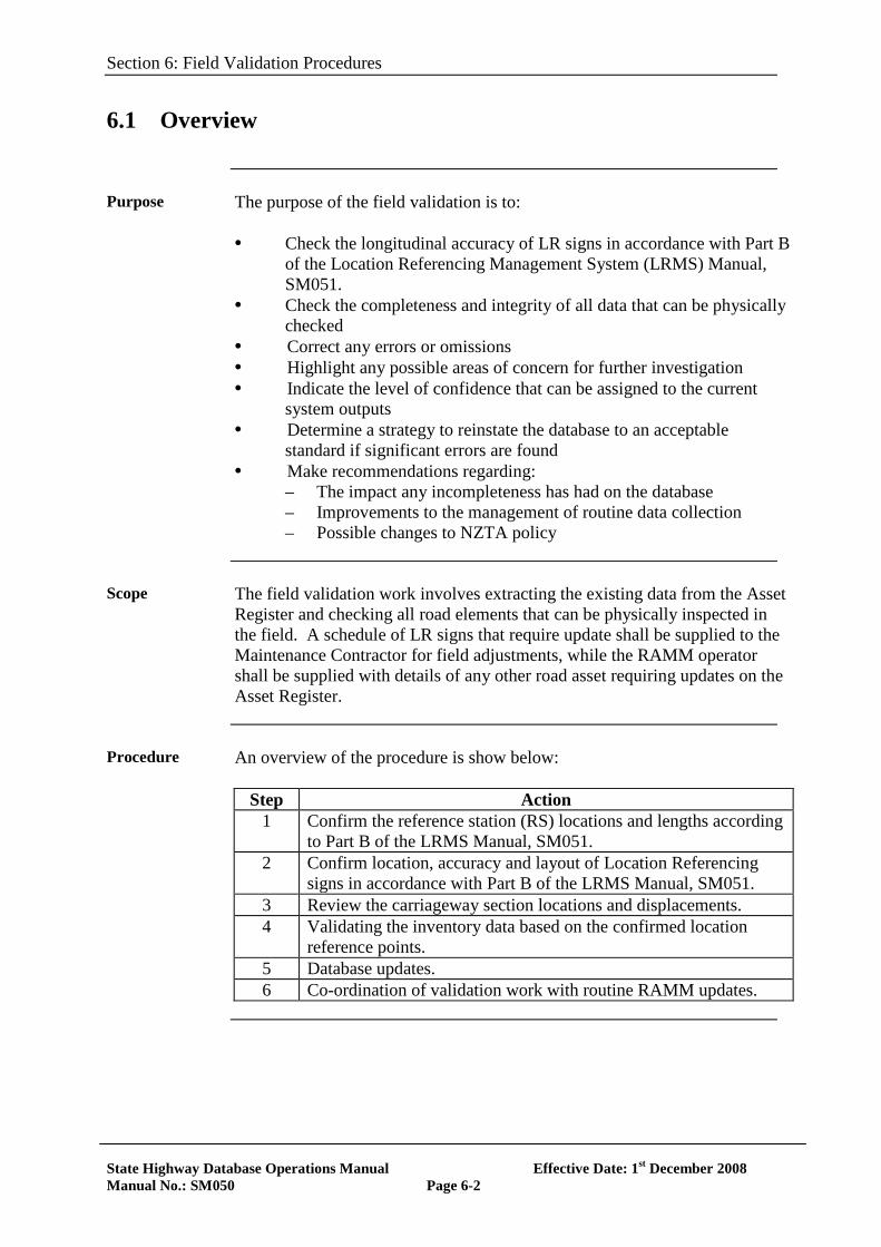
Purpose The purpose of the field validation is to:
• Check the longitudinal accuracy of LR signs in accordance with Part B
of the Location Referencing Management System (LRMS) Manual, SM051.
• Check the completeness and integrity of all data that can be physically checked
• Correct any errors or omissions • Highlight any possible areas of concern for further investigation • Indicate the level of confidence that can be assigned to the current
system outputs • Determine a strategy to reinstate the database to an acceptable
standard if significant errors are found • Make recommendations regarding:
– The impact any incompleteness has had on the database – Improvements to the management of routine data collection – Possible changes to NZTA policy
Scope The field validation work involves extracting the existing data from the Asset
Register and checking all road elements that can be physically inspected in the field. A schedule of LR signs that require update shall be supplied to the Maintenance Contractor for field adjustments, while the RAMM operator shall be supplied with details of any other road asset requiring updates on the Asset Register.
Procedure An overview of the procedure is show below:
Step Action 1 Confirm the reference station (RS) locations and lengths according
to Part B of the LRMS Manual, SM051. 2 Confirm location, accuracy and layout of Location Referencing
signs in accordance with Part B of the LRMS Manual, SM051. 3 Review the carriageway section locations and displacements. 4 Validating the inventory data based on the confirmed location
reference points. 5 Database updates. 6 Co-ordination of validation work with routine RAMM updates.
Section 6: Field Validation Procedures
State Highway Database Operations Manual Effective Date: 1st December 2008 Manual No.: SM050 Page 6-3
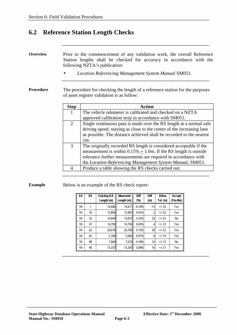
6.2 Reference Station Length Checks
Overview Prior to the commencement of any validation work, the overall Reference
Station lengths shall be checked for accuracy in accordance with the following NZTA’s publication:
• Location Referencing Management System Manual SM051.
Procedure The procedure for checking the length of a reference station for the purposes
of asset register validation is as follow:
Step Action 1 The vehicle odometer is calibrated and checked on a NZTA
approved calibration strip in accordance with SM051. 2 Single continuous pass is made over the RS length at a normal safe
driving speed, staying as close to the centre of the increasing lane as possible. The distance achieved shall be recorded to the nearest 1m.
3 The originally recorded RS length is considered acceptable if the measurement is within 0.15% + 1.0m. If the RS length is outside tolerance further measurements are required in accordance with the Location Referencing Management System Manual, SM051.
4 Produce a table showing the RS checks carried out.
Example Below is an example of the RS check report:
SH RS Existing R/S Measured Diff Diff Allow Accept Length (m) Length (m) (%) (m) Tol. (m) (Yes/No)
1N 1 14,686 14,671 -0.10% -15 +/- 23 Yes
1N 16 15,890 15,892 0.01% 2 +/- 25 Yes
1N 32 14,840 14,872 0.22% 32 +/- 23 No
1N 47 14,790 14,794 0.03% 4 +/- 23 Yes
1N 62 20,670 20,700 0.15% 30 +/- 32 Yes
1N 83 5,700 5,696 -0.07% -4 +/- 10 Yes
1N 88 7,660 7,674 0.18% 14 +/- 13 No
1N 96 13,337 13,347 0.08% 10 +/- 21 Yes
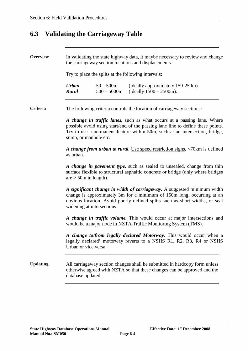
Section 6: Field Validation Procedures
State Highway Database Operations Manual Effective Date: 1st December 2008 Manual No.: SM050 Page 6-4
6.3 Validating the Carriageway Table
Overview In validating the state highway data, it maybe necessary to review and change
the carriageway section locations and displacements. Try to place the splits at the following intervals: Urban 50 – 500m (ideally approximately 150-250m) Rural 500 – 5000m (ideally 1500 – 2500m).
Criteria The following criteria controls the location of carriageway sections:
A change in traffic lanes, such as what occurs at a passing lane. Where possible avoid using start/end of the passing lane line to define these points. Try to use a permanent feature within 50m, such at an intersection, bridge, sump, or manhole etc. A change from urban to rural. Use speed restriction signs, <70km is defined as urban. A change in pavement type, such as sealed to unsealed, change from thin surface flexible to structural asphaltic concrete or bridge (only where bridges are > 50m in length). A significant change in width of carriageway. A suggested minimum width change is approximately 3m for a minimum of 150m long, occurring at an obvious location. Avoid poorly defined splits such as short widths, or seal widening at intersections. A change in traffic volume. This would occur at major intersections and would be a major node in NZTA Traffic Monitoring System (TMS). A change to/from legally declared Motorway. This would occur when a legally declared’ motorway reverts to a NSHS R1, R2, R3, R4 or NSHS Urban or vice versa.
Updating All carriageway section changes shall be submitted in hardcopy form unless
otherwise agreed with NZTA so that these changes can be approved and the database updated.
Section 6: Field Validation Procedures
State Highway Database Operations Manual Effective Date: 1st December 2008 Manual No.: SM050 Page 6-5
6.4 Validating Inventory Data
Overview After confirmation of the location referencing system, the detail table data can
be validated in accordance with Section 2, Asset Register that defines the extent of data requirements for each asset type. It is recommended that the existing data be extracted to spreadsheets for editing either in hardcopy format or laptops. Validation of the data shall include: • Checking the completeness of the data and if necessary collecting any
missing information • Collecting any new information required by NZTA • Correcting any errors in the existing data.
Displacement of Inventory Items
The location referencing signage shall be used for opening and closing surveys. The electronic distance meter shall be reset to the recorded displacements at the start of each new location reference sign. Ideally any small misclose evident at each location referencing sign should be distributed proportionally (rubber banded) over the displacement measurements. This is perhaps more easily achieved where the data is in electronic form. Errors of less than 0.1% can be ignored and between 0.1 – 0.3% should be adjusted out. Major misclose shall be thoroughly investigated and the information resurveyed.
Surfacing Widths
If road width variations are significant their effect should be incorporated into the recorded dimensions. Calculate the relevant area and use the area divided by the length to estimate the average width over the surfacing length. Where there are significant changes in width in a surfacing length > 1.5 for a length > 100m (i.e. crawler lane) a separate record should be created.
Lane Widths At sites where there is a passing lane, the lane width should assume to be the
average of the two lanes.
Surfacing Design Life
Chipseal design life should be similar to that assumed in the FWP (NOMAD). The design life default values for various chip seals as set in RAMM can be found in RAMM Manager – Maintenance/Lookups/Surface/Materials.
Section 6: Field Validation Procedures
State Highway Database Operations Manual Effective Date: 1st December 2008 Manual No.: SM050 Page 6-6
6.4 Validating Inventory Data, continued
Shoulder Widths
Shoulders will usually be of variable width, which will be affected by maintenance methods, blurring at feather edges and seal edge breaks. The “parking rule” can be used as guide to what constitutes as the shoulder. That is, if it is road formation and its slope is not so steep as to make parking uncomfortable, it can be considered as shoulder. It is considered only necessary to remeasure widths when there is a difference between the recorded and measured distance by more than 0.5m over a consistently long length (>100m).
Distance to Seal from SWC
This need only be remeasured when there is a difference between the recorded and measured distance by more than 0.5m over a consistently long length (>100m).
Offsets Should be remeasured when there is a difference between the recorded and
measured distance by more than 0.5m. The exception to this rule is signs, which may have a default of 6m for signs on the main carriageway and 15m for signs on side roads.
Culvert Sizes Culverts should be measured and recorded to the appropriate “nominal” size.
Almost all pipes will have a diameter as a multiple of 75mm and they should be recorded accordingly. Thus a 590 or 620mm diameter pipe should be recorded as 600mm diameter pipe. The next size up would be 675mm diameter and the next size down 525mm diameter. For box culverts a greater flexibility may be used but dimensions should be recorded to the nearest 0.1m. For example a culvert 2.05m wide x 1.25m deep would be recorded as 2.0m x 1.2m.
Barriers Barriers between a divided carriageway should be recorded against the
increasing direction of the road. Partial replacement or an extension to an existing barrier should be a separate record; however, the minimum length for such a record is 5m.
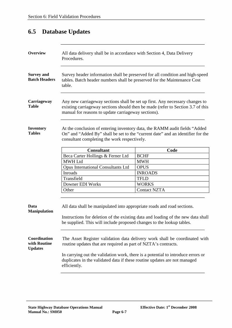
Section 6: Field Validation Procedures
State Highway Database Operations Manual Effective Date: 1st December 2008 Manual No.: SM050 Page 6-7
6.5 Database Updates
Overview All data delivery shall be in accordance with Section 4, Data Delivery
Procedures.
Survey and Batch Headers
Survey header information shall be preserved for all condition and high-speed tables. Batch header numbers shall be preserved for the Maintenance Cost table.
Carriageway Table
Any new carriageway sections shall be set up first. Any necessary changes to existing carriageway sections should then be made (refer to Section 3.7 of this manual for reasons to update carriageway sections).
Inventory Tables
At the conclusion of entering inventory data, the RAMM audit fields “Added On” and “Added By” shall be set to the “current date” and an identifier for the consultant completing the work respectively.
Consultant Code
Beca Carter Hollings & Ferner Ltd BCHF MWH Ltd MWH Opus International Consultants Ltd OPUS Inroads INROADS Transfield TFLD Downer EDI Works WORKS Other Contact NZTA
Data Manipulation
All data shall be manipulated into appropriate roads and road sections. Instructions for deletion of the existing data and loading of the new data shall be supplied. This will include proposed changes to the lookup tables.
Coordination with Routine Updates
The Asset Register validation data delivery work shall be coordinated with routine updates that are required as part of NZTA’s contracts. In carrying out the validation work, there is a potential to introduce errors or duplicates in the validated data if these routine updates are not managed efficiently.
Section 6: Field Validation Procedures
State Highway Database Operations Manual Effective Date: 1st December 2008 Manual No.: SM050 Page 6-8
6.6 Supporting Documentation
Overview Additional to the standard documentation required with data delivery, Section
4, Data Delivery Procedures, a field validation report is required.
Report Requirements
The field validation report shall contain the following components: • An executive summary • A summary of the audit results • Scope of work • Method • Discussion of the audit results • A brief statement describing the reasons for the changes made to each
table • Recommendations for action/improvements to the database.
Example An example of the recommendations could include:
• Field checks required for larger sample of the network • An assessment of the impact any incompleteness has had on the
database • A request for NZTA to confirm their policy regarding the collection of
some data • Responsibility for actions, for example NZTA National Office, NZTA
Regional Office, Network Management Consultant (NMC).
Section 7: Traffic Data
State Highway Database Operations Manual Effective Date: 1st December 2008 Manual No.: SM050 Page 7-1
SECTION 7
TRAFFIC DATA
7.0 Introduction
Overview The use of traffic data and its importance for traffic profiling has increased
dramatically in recent years due to pavement modelling (dTIMS analysis) and also as supportive data for the National State Highway Strategy and Asset Management Plan. This section details the processes in place to update traffic data for the State Highway network.
References Traffic Monitoring System (TMS)
A user manual for the software is distributed with the electronic help file, which is accessible to registered users through the TMS website. http://tms.transit.govt.nz Traffic Monitoring for State Highways (SM052)
In this Section The topics in this section are listed below:
Topic See Page Overview of Process Responsibilities Notification
7-2 7-4 7-5
Section 7: Traffic Data
State Highway Database Operations Manual Effective Date: 1st December 2008 Manual No.: SM050 Page 7-2
7.1 Overview of Process
Process The Annual Average Daily Traffic (AADT) and Loading data from TMS is
transferred to RAMM via the TMS / RAMM interface within February. The up-to-date Traffic and Loading data is loaded into RAMM. Traffic and loading estimates for each RAMM carriageway section is created. These estimates are given a reading date of 31/12/20## (latest year)
TMS and RAMM
Data from TMS is transferred to RAMM. The link between the two systems is established in several ways:
• TMS Count site located by Reference Station and Route Position (RSRP)
• TMS site id • Upper node (RSRP) defining start displacement of Traffic Link • Lower node (RSRP) defining end displacement of Traffic Link
Site Ids The site ID is merely a unique reference for each site, which happens to be
generated using site location information. True location is established from the RSRP.
Site ID format Each site recorded by the system must have a unique identifier in the
format “sssdnnnn” where: sss = State Highway reference - alphanumeric, case sensitive, i.e. use
upper case only d = Direction nnnn = Running distance to site from start of the State Highway
Section 7: Traffic Data
State Highway Database Operations Manual Effective Date: 1st December 2008 Manual No.: SM050 Page 7-3
7.1 Overview of Process, continued
Site ID Direction Codes
The direction (d) must be one of the following values: 0 – Both Directions 1 - Increasing 2 - Decreasing 3 - Increasing ON ramp, number in a clockwise direction from the increasing lane. 4 - Decreasing OFF ramp 5 - Decreasing ON ramp 6 - Increasing OFF ramp 7 – Spare 8 - Roundabaouts 9 is used where there is more than one monitoring site within a kilometre
Example The site ID “00250937” represents:
• Site on State Highway 2 • Decreasing On Ramp • 937 kilometres from the SH origin
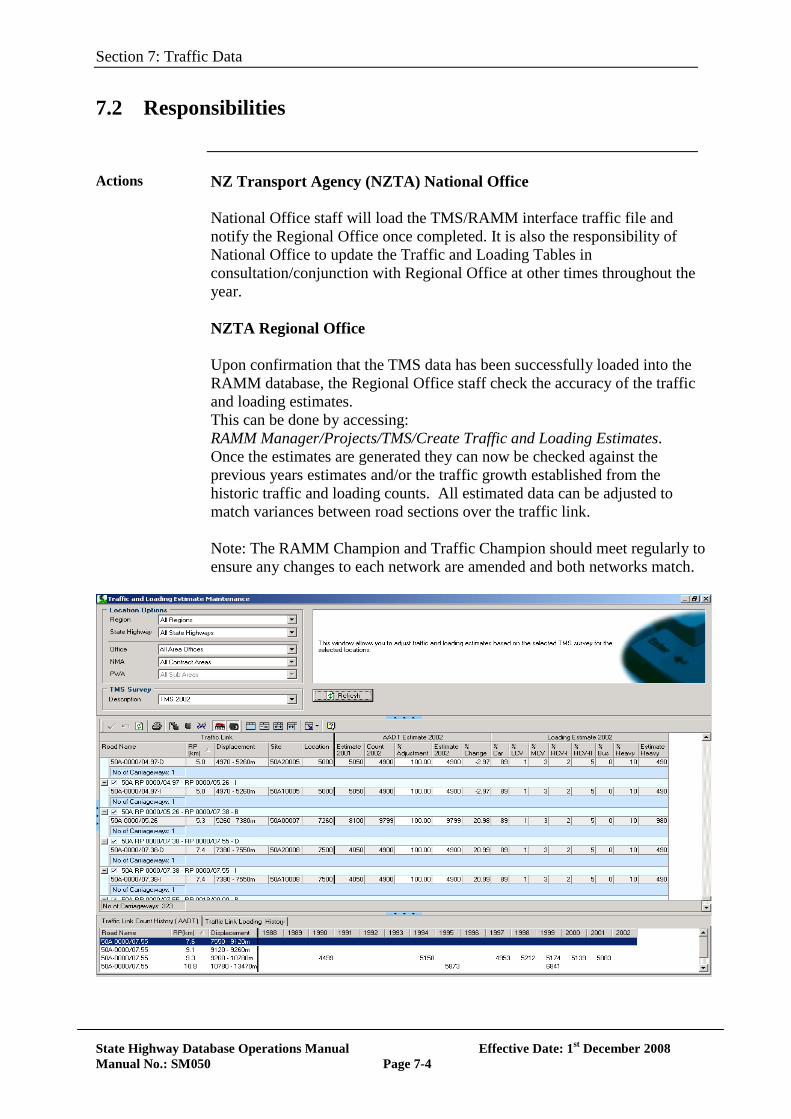
Section 7: Traffic Data
State Highway Database Operations Manual Effective Date: 1st December 2008 Manual No.: SM050 Page 7-4
7.2 Responsibilities
Actions NZ Transport Agency (NZTA) National Office
National Office staff will load the TMS/RAMM interface traffic file and notify the Regional Office once completed. It is also the responsibility of National Office to update the Traffic and Loading Tables in consultation/conjunction with Regional Office at other times throughout the year. NZTA Regional Office Upon confirmation that the TMS data has been successfully loaded into the RAMM database, the Regional Office staff check the accuracy of the traffic and loading estimates. This can be done by accessing: RAMM Manager/Projects/TMS/Create Traffic and Loading Estimates. Once the estimates are generated they can now be checked against the previous years estimates and/or the traffic growth established from the historic traffic and loading counts. All estimated data can be adjusted to match variances between road sections over the traffic link. Note: The RAMM Champion and Traffic Champion should meet regularly to ensure any changes to each network are amended and both networks match.
Section 7: Traffic Data
State Highway Database Operations Manual Effective Date: 1st December 2008 Manual No.: SM050 Page 7-5
7.3 Notification
Notification Once the Regional staff has confidence that the traffic data within RAMM
(inc. the estimates) is acceptable, notification via email shall be sent to NZTA National Office, Asset Database Administrator. Expected completion date for the Traffic profile data shall be in accordance with the Asset Information Annual Planner (Appendix 5 of SHDOM).
Section 8: Transit LTPP – Site Maintenance Database
State Highway Database Operations Manual Effective Date: 1st December 2008 Manual No.: SM050 Page 8-1
SECTION 8
Transit LTPP - Site Maintenance Database
8.0 Introduction
Overview To understand pavement performance the NZ Transport Agency (NZTA) has
established a number of Long-term-Pavement Performance (LTPP) calibration sections in order to monitor the deterioration of pavements. These 300m long sections are established across New Zealand. Data from the LTPP sections are used to calibrate the pavement models used in dTIMS by showing the affect of maintenance activities that have been carried out over the life of the calibration section. Accurate models will enable an accurate forward works programme to be developed and maintained. LTPP Site Maintenance Database is a front-end application to store and deliver maintenance recorded on the NZTA calibration sections (LTPP Sites) to NZTA National Office The functionality of the LTPP-Site Maintenance Database is described in the LTTP-Site Maintenance Database User Manual provided with the application. This section documents the process of delivering the calibration maintenance data to NZTA.
References A user manual for the software is distributed with the application
In this Section The topics in this section are listed below:
Topic See Page Overview of process Responsibilities Supply of Data Location of Sites
8-2 8-3 8-4 8-5
Section 8: Transit LTPP – Site Maintenance Database
State Highway Database Operations Manual Effective Date: 1st December 2008 Manual No.: SM050 Page 8-2
8.1 Overview of Process
Definitions The following definitions are applicable to the LTPP sections:
Benchmark Sections (1km long) – Some LTPP sections overlap or sit within the Benchmark sections. Benchmark sections are used to validate the annual HSD survey. Sterilised LTPP Sections (300m) long) – Sterilised sections are indicted with a red marker post and a Calibration section sign and numbering starting with CS. On these sections only, maintenance to remove hazards (such as pothole filling) are permitted subject to approval from the Asset Information Engineer, NZTA National Office, Highways and Network Operations Group. Non Sterilised LTPP Sections (300m long) – These sections are indicted with blue marker post and numbering of these sections start with CAL. Any maintenance required on these sections may be scheduled in consultation with the Asset Information Engineer, NZTA National Office, Highways and Network Operations Group.
Purpose Maintenance activities recorded for this database are in essence the same as
required for the maintenance activity reporting described in section 4, Maintenance Activities. The only difference is that there is allowance for more accurate and complete storage of all the data items collected during the site investigation/maintenance design. No additional data requirements are specified for this database. The purpose of the database includes:
• Most Network Maintenance Areas (NMA) has between two to five sections within their area. This database is used to capture, store and provide the maintenance information in a consistent format.
• The database facilitates the collation and integration of data with the NZTA master asset system database (currently RAMM) in National Office.
• Through the database and the data delivering process the awareness of the LTPP sections, its purpose and importance is increased.
Section 8: Transit LTPP – Site Maintenance Database
State Highway Database Operations Manual Effective Date: 1st December 2008 Manual No.: SM050 Page 8-3
8.2 Responsibilities
NMM Consultant
The Network Management Consultant is responsible to ensure:
• No unauthorised work. • All maintenance activity work is discussed and agreed with the
Regional Office and NZTA’s Asset Information Engineer prior to the commencement of any maintenance activities.
• Full and accurate data, investigation and design data for any work carried out is provided to NZTA.
Regional Office
The Regional Office is responsible to ensure:
• No unauthorised work. • All maintenance activity work is discussed and agreed with NZTA’s
Asset Information Engineer prior to the commencement of any maintenance activities.
• Safety. • Approval of all Traffic Management Plans for the safe working on the
site, including the LTPP Data Collection Contractor’s TMP.
Data Collection Contractor
The LTPP Data Collection Contractor is responsible for carrying out Detailed Condition Surveys.
NZTA National Office
The National Office is responsible to ensure:
• Integrated Management, management of data collection and LTPP database.
Section 8: Transit LTPP – Site Maintenance Database
State Highway Database Operations Manual Effective Date: 1st December 2008 Manual No.: SM050 Page 8-4
8.3 Supply of Data
Overview NMM Consultant enters all the maintenance data for LTPP Calibration
sections within their region into the TNZ-LTPP maintenance database or provide the data on the LTPP Site Maintenance reporting template, both available from NZTA’s National Asset Information Engineer, even though it is also loaded into RAMM according to Section 4, Data Delivery Procedures. The mandatory fields are limited since the data collected will vary on a case-by-case basis. These fields are indicated in the appropriate input screens.
Delivery Data shall be delivered annually prior to the 1st August.
Disks Maintenance data delivered by the Consultant to NZTA shall be on CD or
DVD and shall include:
• A copy of the database (MDB) or completed template. • Related electronic files such as photos images and other files.
The naming convention of the database and files are described in the user manual.
Section 8: Transit LTPP – Site Maintenance Database
State Highway Database Operations Manual Effective Date: 1st December 2008 Manual No.: SM050 Page 8-5
8.4 Location of Sites
Overview Below is the location of the benchmarking and calibration sites:
Region/NMA SH RS BM Number RP(km) Start
(km) End (km) Sterilised (Y/N)
Texture Measure
Required Y/N
Northland 01N 292 1 0.1 to 1.1 CS 1 0.7 1 Y N
Northland 01N 319 2 13.0 to 14.0 CS 2 13.3 13.6 Y N
Northland 01N 245 3 6.1 to 6.8 CS 3 6.35 6.65 Y N
Northland 12 17 4 7.0 to 8.0 CAL 4 14.39 14.69 No N
Northland 12 185 5 7.95 to 10.75 CAL 5 10.45 10.75 No N
Northland 01N 20 6 9.37 to 10.44 CAL 6 10.5 10.8 No N
Northland 15A 0 CS 62 0.68 0.98 Y N
Auckland 01N - Inc. 431 7 1.0 to 2.0 CS 7a 1 1.3 Y N
Auckland 01N - Inc. 431 7 1.0 to 2.0 CS 7b 1.95 2.25 Y N
Auckland 01N - Inc. 461 8 3.0 to 4.0 CS 8a 3.1 3.4 Y N
Auckland 01N - Inc. 461 8 3.0 to 4.0 CS 8b 3.7 4 Y N
Central Waikato 01N 625 11 6.63 to 7.70 CS 11 7.2 7.5 Y Y
Central Waikato 5 169 12 6.82 to 7.82 CAL 12 7.2 7.5 No Y
Central Waikato 01N 777 13 2.32 to 4.18 CS 13a 3.2 3.5 Y N
Central Waikato 01N 777 13 2.32 to 4.18 CAL 13b 3.88 4.18 No N
East Waikato 29 50 14 0.02 to 1.20 CS 14 0.55 0.85 Y Y
West Waikato 01N - Inc. 574 16 4.00 to 5.00 CS 16 4 4.3 Y N
West Waikato 2 0 17 4.80 to 5.60 CAL 17 5 5.3 No N
PSMC 3 36 18 1.20 to 2.20 CAL 18 1.6 1.9 No N
PSMC 3 16 19 13.00 to 14.00 CAL 19 13.5 13.8 No N
PSMC 31 0 20 5.50 to 6.50 CS 20 5.4 5.7 Y Y
Gisborne 35 250 21 9.57 to 10.50 CS 21 10.15 10.45 Y Y
Gisborne 2 375 22 0.68 to 1.56 CS 22 1.16 1.56 Y Y
Gisborne 2 474 23 5.24 to 5.96 CAL 23 5.3 5.6 No Y
Hawkes Bay 2 544 24 12.47 to 13.20 CS 24 12.6 13.1 Y Y
Hawkes Bay 2 729 25 8.56 to 9.60 CAL 25a 8.8 9.1 No Y
Hawkes Bay 2 729 25 8.56 to 9.60 CAL 25b 9.1 9.4 No Y
Hawkes Bay 5 204 26 13.63 to 14.82 CS 26 14.2 14.5 Y Y
Hawkes Bay 5 233 27 10.0 to 11.0 CAL 27a 10 10.3 No Y
Hawkes Bay 5 233 27 10.0 to 11.0 CAL 27b 10.3 10.6 No Y
West Wanganui 01N 815 28 11.71 to 12.90 CS 28 11.8 12.1 Y Y
West Wanganui 4 127 29 8.42 to 9.42 CS 29 8.4 8.7 Y Y
West Wanganui 4 223 30 3.05 to 4.05 CAL 30 3.1 3.4 No Y
East Wanganui 01N 985 31 0.50 to 1.50 CS 31 0.6 0.9 Y Y
East Wanganui 2 751 32 4.52 to 5.52 CAL 32 4.52 4.82 No Y
West Wanganui 3 258 33 0.55 to 1.75 CS 33 4.1 4.4 Y Y
West Wanganui 45 97 34 4.49 to 5.97 CAL 34 5.1 5.5 No Y
Wellington 01N 995 35 14.4 to 15.4 CAL 35 14.4 14.8 No Y
Wellington 2 858 36 9.0 to 10.0 CS 36 9 9.3 Y Y
Rotorua DC 5 29 R1 No Benchmark CAL 53 1.4 1.7 No Y
Rotorua DC 5 77 R3 11.7-12.7 CS 55 11.7 12 Y N
Rotorua DC 30 131 R4 4.4-5.4 CS 56 4.4 4.7 Y N
Rotorua DC 30 170 R5 9.1-10.1 CS 57 9.1 9.4 Y N
Rotorua DC 30 147 R6 No Benchmark CAL 54 8.06 8.36 No Y
Rotorua DC 38 0 R8 14.4-15.4 CAL 58 16.83 17.13 No N
Rotorua DC 5 47 R11 0.8-1.8 CAL 59 1.22 1.52 No N
Section Number
Calibration Section / SiteExisting Benchmark Site
To be Established
North Island
Section 8: Transit LTPP – Site Maintenance Database
State Highway Database Operations Manual Effective Date: 1st December 2008 Manual No.: SM050 Page 8-6
8.4 Location of Sites, continued
Region SH RS BM Number RP(km) Start
(km) End (km) Sterilised (Y/N)
Texture Measure
Required Y/N
Marlborough 63 46 37 4.586 to 6.000 CAL 37a 4.7 5 No N
Marlborough 63 46 37 4.586 to 6.000 CS 37b 5.5 5.8 Y N
Marlborough 01S 18 38 1.405 to 2.028 CAL 38 1.5 1.8 No N
Nelson 6 131 39 16.0 to 17.0 CS 39 16.15 16.45 Y N
Nelson 6 225 40 10.0 to 11.0 CS 40 10 10.3 Y N
North Canterbury 01S 284 41 7.5 to 8.5 CAL 41 7.8 8.1 No N
North Canterbury 73 90 42 2.0 to 3.0 CS 42 2.5 2.8 Y N
South Canterbury 01S 447 43 4.0 to 5.0 CAL 43 4.5 4.8 No N
South Canterbury 8 99 44 3.5 to 4.5 CS 44 4 4.3 Y N
West Coast 6 445 45 12.5 to 13.5 CAL 45a 12.7 13 No N
West Coast 6 445 45 12.5 to 13.5 CS 45b 13.1 13.4 Y N
West Coast 7 239 46 1.5 to 2.5 CS 46 3 3.3 Y N
Coastal Otago 01S 618 48 8.5 to 9.5 CAL 48 9.1 9.4 No N
Coastal Otago 01S 729 49 11.5 to 12.5 CS 49 12 12.3 Y N
Coastal Otago 8 417 51 2.0 to 3.0 CAL 51 2.5 2.8 No N
Coastal Otago 83 0 52 4.0 to 5.0 CAL 52a 4 4.3 No N
Coastal Otago 83 0 52 4.0 to 5.0 CS 52b 4.6 4.9 Y N
Southland 01S 872 53 8.02 to 9.02 N/A N/A N/A N/A N/A N
Southland 6 1111 54 0.35 to 1.35 N/A N/A N/A N/A N/A N
Southland 01S 933 55 0.56 to 1.56 N/A N/A N/A N/A N/A N
Nelson 6 196 56 8.0 to 9.0 N/A N/A N/A N/A N/A N/A
Coastal Otago 83 96 CS 50a 7.5 7.8 Y NTo be Established
Section Number
Existing Benchmark Site Calibration Section / Site
South Island
Section 9: Communications Policy
State Highway Database Operations Manual Effective date: 1st December 2008 Manual No.: SM050 Page 9-1
SECTION 9
COMMUNICATIONS POLICY
9.0 Overview
Purpose This policy outlines how people should communicate in relation to the
operation of RAMM for the NZ Transport Agency (NZTA).
In this Section The topics in this section are listed below:
Topic See Page Data Updates Outages User Requests User Queries and Problems Changes to the System Other Situations
9-2 9-4 9-6 9-7 9-8 9-9
General Guidelines
In general:
• Communications relating to NZTA RAMM databases and the use of RAMM on NZTA databases should occur with the Asset Database Administrator (or deputy) in the first instance;
• Communications on day-to-day issues with RAMM data for a Network Management Area should occur through the local NZTA Area Engineer or RAMM Champion; and
• The Asset Database Administrator liaises between NZTA and CJN Technologies Ltd.
Section 9: Communications Policy
State Highway Database Operations Manual Effective date: 1st December 2008 Manual No.: SM050 Page 9-2
9.1 Data Updates
Scope This covers notification of RAMM data being updated.
Updating data includes adding, deleting or altering records. Classes of data affected include:
• Road names • Inventory data • Forward Works programmes • High Speed data • Traffic data • Falling Weight Deflectometer data • Maintenance Activity data • Condition Rating data
Purpose Data users need to know when data that they may want to use has been
updated. For example, a consultant may wish to know when the traffic data for his or her area has been loaded so that they can proceed with a dTIMS model run, or NZTA National Office staff may want to know when all the reseal data for an area has been loaded so that they can run performance reports.
Advance Notice of Network Changes
Prior to performing a network change the Location Referencing Management System Administrator (or someone he/she delegates) should contact the Network Management Consultant or Contractor (in the case of a Performance-Specified Maintenance Contract) to arrange a convenient time to perform this change.
Data Updated by Consultants or Contractors
When a contractor or consultant has performed changes to a NZTA database, he/she should inform the local NZTA Regional or sub-office as specified in the State Highway Database Operations Manual. The local RAMM Champion should then forward this information to a suitable staff member of the Asset Information Group at National Office.
Section 9: Communications Policy
State Highway Database Operations Manual Effective date: 1st December 2008 Manual No.: SM050 Page 9-3
9.1 Data Updates, continued
Data Updated by NZTA National Office
Within 24 hours of data being updated by NZTA National Office, a member of the Asset Information Group or a deputy will inform the relevant RAMM Champion(s) or Area Engineer(s). This includes but is not necessarily limited to:
• Network changes • Rolling-over of the Forward Works programme • High Speed data • Traffic volume and loading data • Falling Weight Deflectometer data
Section 9: Communications Policy
State Highway Database Operations Manual Effective date: 1st December 2008 Manual No.: SM050 Page 9-4
9.2 Outages
Scope For the purpose of this policy an outage is an interruption to service normally
expected by users of NZTA's RAMM system. An outage can have a number of causes including:
• A problem with communications (e.g., a break in the network or a Citrix problem);
• A problem with the database (e.g., grossly corrupt data or a problem with the database engine);
• A problem with the RAMM server (i.e., a hardware failure); • An upgrade of software or hardware; or • An interruption to the power supply at NZTA.
Outages fall into two categories:
• planned outages for activities such as upgrades or tests of power supplies; and
• unplanned outages, which occur as a result of a problem. This section covers notification of planned outages and communication on unplanned outages.
Purpose Users need to know about outages so that they can plan their work.
Planned Outages
If the outage is due to a database change or upgrade, on an upgrade to the operating system, the database engine or to RAMM, the Asset Database Administrator or deputy should inform all users of:
• When the outage will occur; • The reason for the outage; and • When the users could reasonably expect to be able to use the system
again. This message will be sent by email and at least 48 hours prior to the outage occurring. The Asset Database Administrator may also inform the RAMM Champions by telephone and/or let users know in a written circular such as A Message to the Flock.
Section 9: Communications Policy
State Highway Database Operations Manual Effective date: 1st December 2008 Manual No.: SM050 Page 9-5
9.2 Outages, continued
Unplanned Outages
When an unplanned outage occurs, the Asset Database Administrator will inform all affected users as soon as possible, by email, of:
• The cause of the outage; and • An estimate of when the problem may be fixed.
If email is unavailable but telephones are working, the Asset Database Administrator will phone this message to those users considered best to be informed under the circumstances. This will generally be:
• The NZTA RAMM Champions in affected Offices; and • The National RAMM Contacts for affected Network Management
Consultants or Contractors. In the event of a major disaster such as an earthquake, neither of the above courses of action may be available.
Section 9: Communications Policy
State Highway Database Operations Manual Effective date: 1st December 2008 Manual No.: SM050 Page 9-6
9.3 User Requests
Scope This covers requests for new users or changes to existing users.
Purpose The Asset Database Administrator needs to be informed when there is a new
RAMM user or an existing user needs authorities or details changed, so that the user can be set up or changes made. Once this has been done the new user needs to know that he or she can use RAMM.
Making the Request
People, who want to become NZTA RAMM users or change their user details, should make their request in the first instance to their local NZTA Regional RAMM Champion or Area Engineer if they are:
• NZTA Regional staff • NMC’s • Contractors
All others should contact the Asset Database Administrator directly. The Access Policy (Section 10 of this manual) outlines levels of access.
Informing the User
When a request for a new or changed user has been satisfied the Asset Database Administrator will let the user who made the request know that he or she can now use RAMM or that his or her permissions have been changed.
Section 9: Communications Policy
State Highway Database Operations Manual Effective date: 1st December 2008 Manual No.: SM050 Page 9-7
9.4 User Queries and Problems
Scope This covers possible bugs, questions of procedure, codes etc and how-to type
questions.
Purpose Users need to know how to obtain assistance. NZTA also needs to avoid
undue disruption to its activities.
Faults A user who cannot log in to RAMM should contact the Asset Database
Administrator or the Asset Information Engineer unless the problem is obviously a connection problem (e.g. a Citrix problem). In this case the user should contact CJN Technologies.
Possible Bugs NZTA needs to know of possible problems with the software it is using so
users should report possible bugs encountered while using NZTA's RAMM system to the Asset Database Administrator.
Questions of Procedure
Users who have a query about procedures should contact the Asset Database Administrator or the Asset Information Engineer.
Lookup Codes For enquiries about new inventory lookup codes, contact the Asset
Information Engineer at NZTA’s National Office. .
Application Help
NZTA staff may contact the Asset Database Administrator if they need help with RAMM. Staff of Network Maintenance Consultants or Contractors should contact their company RAMM Champions for assistance. The Asset Database Administrator will advise other users of whom to contact for assistance, when they are notified that they have access to NZTA's RAMM system.
Section 9: Communications Policy
State Highway Database Operations Manual Effective date: 1st December 2008 Manual No.: SM050 Page 9-8
9.5 Changes to the System
Scope This covers system upgrades to:
• Hardware; • The operating system; • The database server software; and • RAMM.
Purpose Users need to know if and how changes will affect how they operate the
system. For example, there may be a change in performance or a change in the user interface. Also, upgrades may involve an outage. Users therefore need to be informed so that they can plan their work (see Outages).
Database Server Software Upgrades
The Asset Database Administrator should inform NZTA RAMM Champions and Network Maintenance Consultant/Contractor contacts of any expected outage.
Upgrades to RAMM
1. The Asset Database Administrator should inform NZTA RAMM Champions and Network Maintenance Consultant/Contractor Contacts of a general plan of how and when a major upgrade (i.e. an upgrade involving a change in the database structure) will be implemented for NZTA databases, including when and if, any outage will occur.
2. The Asset Database Administrator should describe major changes contained in the upgrade in A Message to the Flock and also describe these changes to NZTA RAMM Champions and Network Maintenance Consultant/Contractor contacts by email or telephone.
Section 9: Communications Policy
State Highway Database Operations Manual Effective date: 1st December 2008 Manual No.: SM050 Page 9-9
9.6 Other Situations
Scope This section covers:
• A Message to the Flock • The annual schedule of NZTA asset information activities • Standing Instructions • Consultation with consultants and contractors • Guiding principle
A Message to the Flock
The Asset Information Team issues a newsletter from time-to-time to:
• Remind users of data deliverables that are due, • Remind users of procedures, • Advise users of changes, • Provide tips in the use of RAMM, • Notifying users of any changes to SHDOM and, • Notification of SHDOM version updates
Although ‘A Message to the Flock’ mainly covers RAMM matters, it also provides information about other NZTA asset information systems relevant to RAMM users.
Standing Instructions
Standing instructions are usually contained in manuals. The principal manuals relating to the use of RAMM at NZTA are:
• State Highway Database Operations Manual – SM050; • Location Referencing Management System Manual – SM051; • Annual Plan Instructions Manual – SM018; • State Highway Professional Services Contract Proforma Manual –
SM030; and • RAMM Road Condition Rating and Roughness Manual.
Standing instructions are sometimes issued in Network Operations Memoranda and later incorporated into relevant manuals.
Section 9: Communications Policy
State Highway Database Operations Manual Effective date: 1st December 2008 Manual No.: SM050 Page 9-10
9.6 Other Situations, continued
Annual Schedule of Asset Information Activities
Every year the Asset Information Team issues the Asset Information Annual Planner. Its purpose is to advise users of NZTA’s RAMM system and suppliers of the principal asset information system activities throughout the year, including deadlines for the delivery of data. The Asset Information Annual Planner is an Appendix (currently Appendix 5) of the State Highway Database Operations Manual and is in the format of a wall planner.
Consultation with Consultants and Contractors
NZTA will consult with consultants and contractors on matters related to asset information both formally and informally as needed.
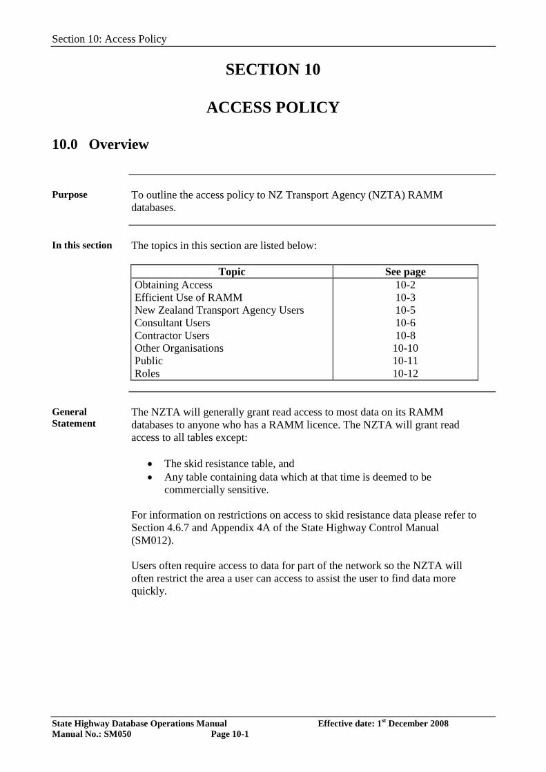
Section 10: Access Policy
State Highway Database Operations Manual Effective date: 1st December 2008 Manual No.: SM050 Page 10-1
SECTION 10
ACCESS POLICY 10.0 Overview
Purpose To outline the access policy to NZ Transport Agency (NZTA) RAMM
databases.
In this section The topics in this section are listed below:
Topic See page Obtaining Access Efficient Use of RAMM New Zealand Transport Agency Users Consultant Users Contractor Users Other Organisations Public Roles
10-2 10-3 10-5 10-6 10-8 10-10 10-11 10-12
General Statement
The NZTA will generally grant read access to most data on its RAMM databases to anyone who has a RAMM licence. The NZTA will grant read access to all tables except:
• The skid resistance table, and • Any table containing data which at that time is deemed to be
commercially sensitive. For information on restrictions on access to skid resistance data please refer to Section 4.6.7 and Appendix 4A of the State Highway Control Manual (SM012). Users often require access to data for part of the network so the NZTA will often restrict the area a user can access to assist the user to find data more quickly.
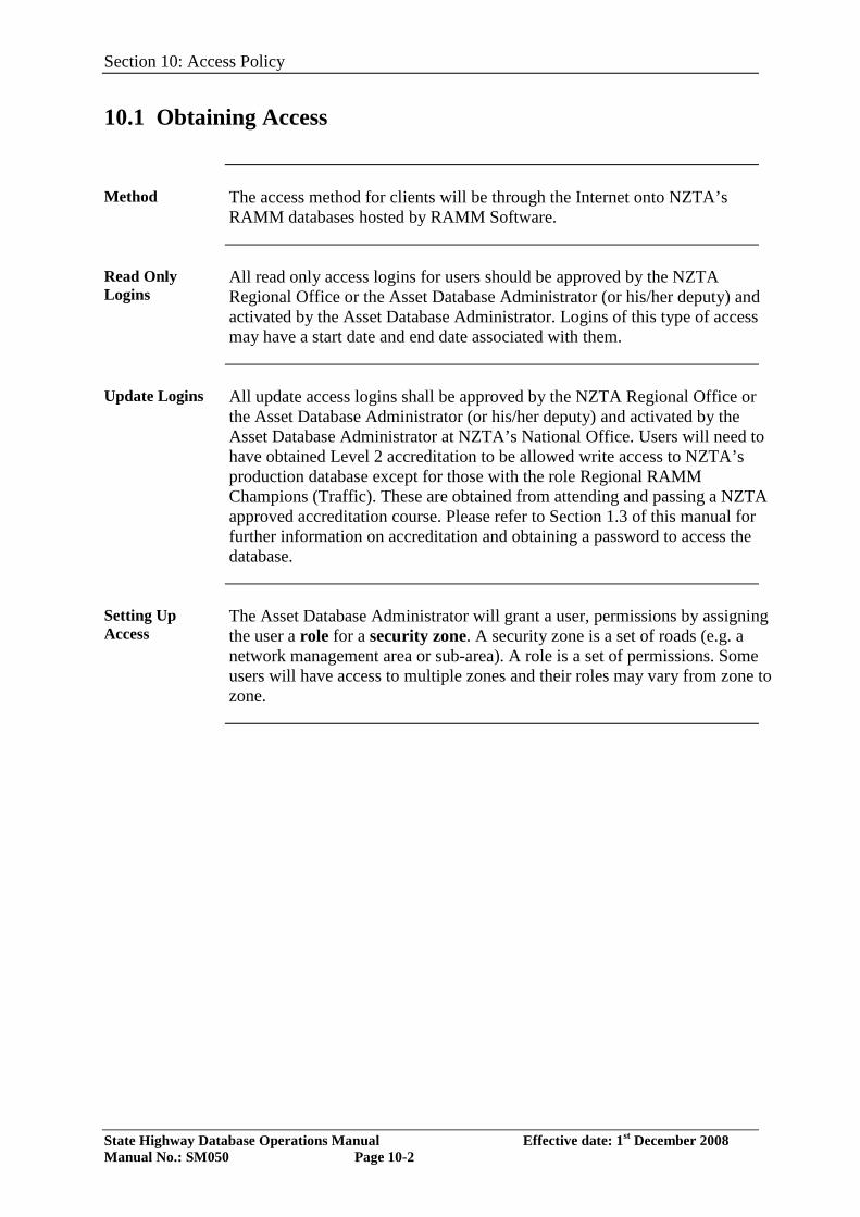
Section 10: Access Policy
State Highway Database Operations Manual Effective date: 1st December 2008 Manual No.: SM050 Page 10-2
10.1 Obtaining Access
Method The access method for clients will be through the Internet onto NZTA’s
RAMM databases hosted by RAMM Software.
Read Only Logins
All read only access logins for users should be approved by the NZTA Regional Office or the Asset Database Administrator (or his/her deputy) and activated by the Asset Database Administrator. Logins of this type of access may have a start date and end date associated with them.
Update Logins All update access logins shall be approved by the NZTA Regional Office or
the Asset Database Administrator (or his/her deputy) and activated by the Asset Database Administrator at NZTA’s National Office. Users will need to have obtained Level 2 accreditation to be allowed write access to NZTA’s production database except for those with the role Regional RAMM Champions (Traffic). These are obtained from attending and passing a NZTA approved accreditation course. Please refer to Section 1.3 of this manual for further information on accreditation and obtaining a password to access the database.
Setting Up Access
The Asset Database Administrator will grant a user, permissions by assigning the user a role for a security zone. A security zone is a set of roads (e.g. a network management area or sub-area). A role is a set of permissions. Some users will have access to multiple zones and their roles may vary from zone to zone.
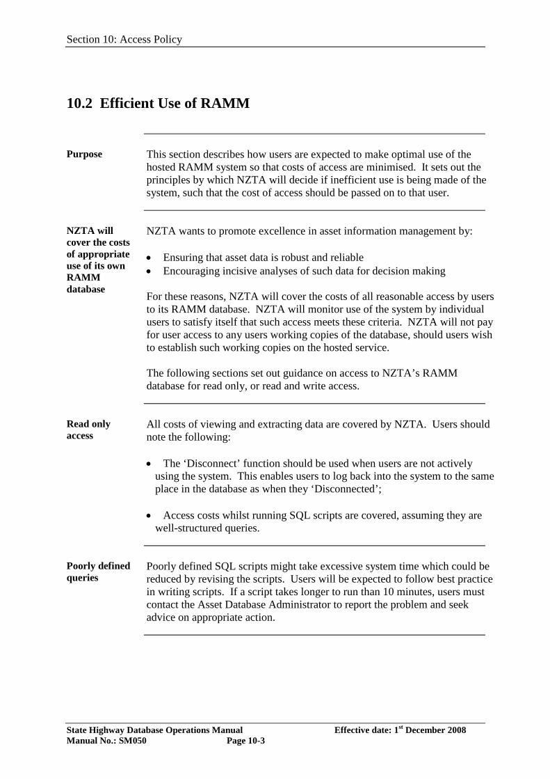
Section 10: Access Policy
State Highway Database Operations Manual Effective date: 1st December 2008 Manual No.: SM050 Page 10-3
10.2 Efficient Use of RAMM
Purpose This section describes how users are expected to make optimal use of the
hosted RAMM system so that costs of access are minimised. It sets out the principles by which NZTA will decide if inefficient use is being made of the system, such that the cost of access should be passed on to that user.
NZTA will cover the costs of appropriate use of its own RAMM database
NZTA wants to promote excellence in asset information management by: • Ensuring that asset data is robust and reliable • Encouraging incisive analyses of such data for decision making For these reasons, NZTA will cover the costs of all reasonable access by users to its RAMM database. NZTA will monitor use of the system by individual users to satisfy itself that such access meets these criteria. NZTA will not pay for user access to any users working copies of the database, should users wish to establish such working copies on the hosted service. The following sections set out guidance on access to NZTA’s RAMM database for read only, or read and write access.
Read only access
All costs of viewing and extracting data are covered by NZTA. Users should note the following: • The ‘Disconnect’ function should be used when users are not actively
using the system. This enables users to log back into the system to the same place in the database as when they ‘Disconnected’;
• Access costs whilst running SQL scripts are covered, assuming they are well-structured queries.
Poorly defined queries
Poorly defined SQL scripts might take excessive system time which could be reduced by revising the scripts. Users will be expected to follow best practice in writing scripts. If a script takes longer to run than 10 minutes, users must contact the Asset Database Administrator to report the problem and seek advice on appropriate action.
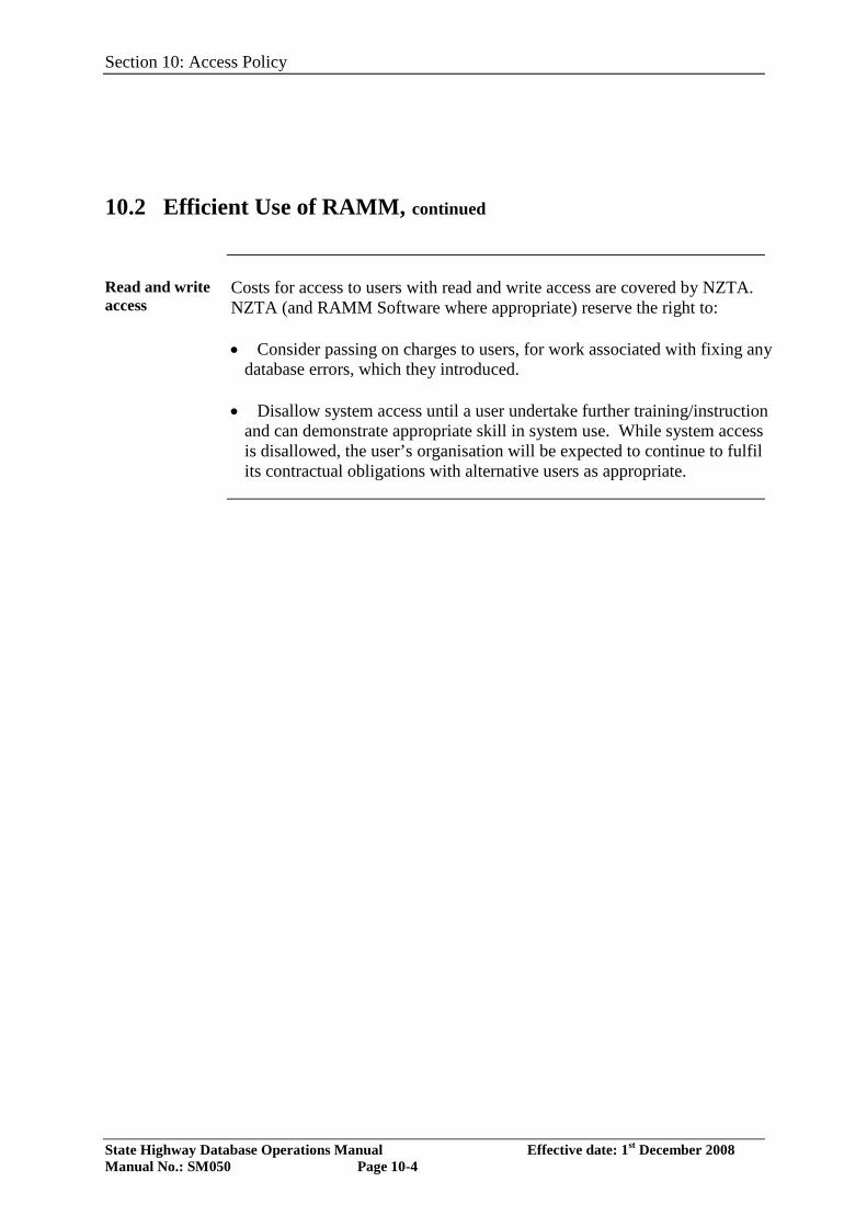
Section 10: Access Policy
State Highway Database Operations Manual Effective date: 1st December 2008 Manual No.: SM050 Page 10-4
10.2 Efficient Use of RAMM, continued
Read and write access
Costs for access to users with read and write access are covered by NZTA. NZTA (and RAMM Software where appropriate) reserve the right to: • Consider passing on charges to users, for work associated with fixing any
database errors, which they introduced.
• Disallow system access until a user undertake further training/instruction and can demonstrate appropriate skill in system use. While system access is disallowed, the user’s organisation will be expected to continue to fulfil its contractual obligations with alternative users as appropriate.
Section 10: Access Policy
State Highway Database Operations Manual Effective date: 1st December 2008 Manual No.: SM050 Page 10-5
10.3 New Zealand Transport Agency Users
Reasons for Access
As asset owner NZTA needs to have access to ensure all their suppliers are maintaining the database to the standards as prescribed in their contracts as well as adding to the database the data that they are responsible for. NZTA staff also requires access for management and reporting purposes.
Access Levels All NZTA staff may have read only access to the database and may have the
role of full viewer. NZTA staff who require write access to the database will have to obtain the necessary accreditation certificate as outlined in Section 1.3 of this manual. This requirement may be waived by the Asset Database Administrator for staff involved in the update of traffic and loading data.
Section 10: Access Policy
State Highway Database Operations Manual Effective date: 1st December 2008 Manual No.: SM050 Page 10-6
10.4 Consultant Users
Reasons for Access
The following are the reasons why consultants need access to RAMM:
NMM/Hybrid Consultant and PSMC Contractor
The network maintenance manager has ultimate contractual responsibility for the RAMM data in his/her area. As such he/she shall have a RAMM Level 2 accredited person who are able to update the database with any changes that happen on his/her Network in accordance with the specific inventory and condition data tables described in SHDOM (SM050)
Network Bridge Consultant
In some cases bridges may be stored in the asset database. The NMA Bridge Consultant is the person responsible for updating bridge data for a network management area As such he/she shall be a RAMM Level 2 accredited person.
Design/ Supervision Consultant
The Design/Supervision Consultant has the responsibility of providing updated data to NZTA following the construction of any new piece of highway or off-road structure. He/she should have a RAMM expert or employ one as a sub-consultant to supply records to the network maintenance manager.
Scheme Consultant
The Scheme Consultant is the Consultant who needs access to RAMM data to help them put a scheme plan together and does the necessary project evaluation work.
Management Support Quality Assurance Consultant
The Management Support Quality Assurance Consultant has the responsibility of loading high quality, high speed, skid resistance and falling weight deflectometer data into NZTA’s databases. He/she needs to be able to view and update these data for the entire country as well as update survey header data.
Valuation Consultant
The Valuation Consultant has the responsibility of providing an annual valuation of State Highway assets to the NZTA. He/she needs the ability to view all assets, and update data pertaining to valuation.

Section 10: Access Policy
State Highway Database Operations Manual Effective date: 1st December 2008 Manual No.: SM050 Page 10-7
10.4 Consultant Users, continued
Access Rights Requirements for NMM/Hybrid Consultant & PSMC Contractor
The network maintenance manager needs read and write access rights to all major inventory tables as well as the forward work programme, maintenance cost and rating tables. He/she should also have Import, Export and SQL rights to these tables. Employees of consultants will have full viewer, NMC or NMC super-user roles assigned to them depending on their level of accreditation (refer to section 1.3). These permissions should be for the area he/she is responsible for and only for the duration of that contract. In certain proven cases, it will be possible for some users to have ‘write’ access to other network areas apart from their own. E.g. where the consultant is acting as MSQA for another NMA.
Access Requirements for Network Bridge Consultant
The network bridge consultant needs read and write access rights to the bridge tables. He/she should also have Import, Export and SQL read rights to these tables.
Access Rights Requirements for Design and or Supervision Consultant
The Design/Supervision Consultant shall have read only access to the database for the area that the work he/she is responsible for is included in. The Design/Supervision Consultant will also need export rights to the major inventory tables to enable him/her to download to external systems. Therefore, he/she will have a viewer role.
Access Rights Requirements for Scheme Consultant
The Scheme Consultant shall have read only access to the database for the area that the work he/she is responsible for is included in. The Scheme Consultant will also need export rights to the major inventory & condition tables to enable him/her to download to external systems. Therefore, he/she will have a full viewer role.
Access Rights for Management Support Quality Assurance Consultant
The Management Support Quality Assurance Consultant shall have read access to all operational databases and write access to high speed, skid resistance and falling weight deflectometer data. He/she will be given an MSQA role in most if not all areas.
Access Rights Valuation Consultant
The Valuation Consultant needs to be able to update the valuation fields of all inventory tables and to update valuation snapshots. He/she will be given the valuation consultant role.
Section 10: Access Policy
State Highway Database Operations Manual Effective date: 1st December 2008 Manual No.: SM050 Page 10-8
10.5 Contractor Users
Reasons for Access
The following are the reasons for contractors to have access to RAMM.
Pavement Maintenance Contractor
The Pavement, Drainage and Emergency Works Contractor is responsible for delivering updated RAMM data relating to maintenance works as well as scheduling preventative maintenance. The contractor needs access to existing RAMM records along with the Forward Work Program and historical maintenance costs. Some contractors may be contracted to maintain inventory data for their area. Some may also use RAMM Contractor.
Traffic Services Contractor
The Traffic Services Contractor is responsible for the provision of updated sign data to the Consultant or the PSMC Contractor. He/she needs to have access to existing signs information to achieve this. Some traffic services contractors may be contracted to maintain data in the database for signs in their area.
Lighting Contractor
The Lighting Contractor may be responsible for the provision of updated lighting data to the Consultant or the PSMC Contractor or may be responsible for maintaining this data in the database for their area. He/she needs to have access to existing lighting information to achieve this.
Road Marking Contractor
The Road Marking Contractor may be responsible for the provision of updated road marking data to the Consultant or the PSMC Contractor or may be responsible for maintaining this data in the database for their area. He/she needs to have access to existing road marking information to achieve this.
Surfacing Contractor
The surfacing contractor needs access to previous surfacing data to determine surface thickness when doing seal designs and hsd_texture to assess current texture variability. He/she also needs access to lookup tables so he/she can deliver the correct data back to the NMM consultant.
Project Contractor
The project contractor needs access to lookup table information and existing inventory information so he/she can provide data back to the consultant who is responsible for updating of the database.
Section 10: Access Policy
State Highway Database Operations Manual Effective date: 1st December 2008 Manual No.: SM050 Page 10-9
10.5 Contractor Users, continued
Access Rights Requirements for NMM Contractor
Each Contractor has read only rights and will have the approval granted through their NZTA Regional Office before the Asset Database Administrator sets up access. This contractor needs read only rights for his/her area only and for the duration of the contract. Where the contractor is responsible for updating inventory data, Level 2 accredited employees of the contractor will be granted write access with the role of general contractor.
Traffic Services Contractor
Each Contractor has read only rights and will have the approval granted through their NZTA Regional Office before the Asset Database Administrator sets up access. If accredited to Level 2, this contractor should have read and write access rights to the signs table for his/her area only and for the duration of the contract and will be given the role of signs contractor.
Lighting Contractor
Each Contractor has read only rights and will have the approval granted through their NZTA Regional Office before the Asset Database Administrator sets up access. If accredited to Level 2, this contractor should have read and write access rights to the street lighting tables for his/her area only and for the duration of the contract and will be given the role of lighting contractor.
Road Marking Contractor
Each Contractor has read only rights and will have the approval granted through their NZTA Regional Office before the Asset Database Administrator sets up access. If accredited to Level 2, this contractor should have read and write access rights to the markings table for his/her area only and for the duration of the contract and will be given the role of markings contractor.
Surfacing Contractor
Each Contractor has read only rights and will have the approval granted through their NZTA Regional Office before the Asset Database Administrator sets up access. The surfacing contractor needs read only rights to the hsd_texture, c_surface table and the surface_structure table only so will be granted access with a viewer role. This should be limited to his/her contract area only. If accredited to Level 2, this contractor should have read and write access rights to the c_surface table for his/her area only and for the duration of the contract and will be given the role of markings contractor.
Project Contractor
The project contractor needs read access to all inventory information for the area he/she is working in and for the duration of his project contract. He/she will be granted access with a viewer role.
Section 10: Access Policy
State Highway Database Operations Manual Effective date: 1st December 2008 Manual No.: SM050 Page 10-10
10.6 Other Organisations
Government Agencies
From time to time government agencies like Police and Statistics departments may require read access. These should be dealt with on a case-by-case basis with access role of viewer.
Educational Institutes
From time to time educational institutes may wish to have access to the RAMM database for research projects. This should be read only access and be approved through the NZTA Regional Offices or National Office on a project-by-project basis.
Other Commercial Entities
This should be read only access with a viewer or full viewer role (in the case of a specialist consultant) and be approved by NZTA Regional Office or National Office on a case-by-case basis. The regional office should be aware of what the data is being used for so that it doesn’t bring a claim back on NZTA e.g. Insurance Companies.
Section 10: Access Policy
State Highway Database Operations Manual Effective date: 1st December 2008 Manual No.: SM050 Page 10-11
10.7 Public
Access for Information
It is envisaged in the future that members of the public may well have a need for information held in the RAMM database. This should be dealt with on a case-by-case basis and approval given through the appropriate NZTA Regional Office.
Section 10: Access Policy
State Highway Database Operations Manual Effective date: 1st December 2008 Manual No.: SM050 Page 10-12
10.8 Roles
Explanation A role is a collection of permissions and is given a name. For instance, most
users will have a viewer role, which means that they will be able to have read access in RAMM (except skid resistance) plus the ability to export databases and tables. Below are different roles that a user may have when using a NZTA RAMM database.
Viewer Read-only access to all condition and inventory tables except the skid
resistance table, the road names table and maintenance cost data using RAMM and RAMM SQL, ability to export files except the skid resistance table or a database.
Full Viewer As for viewer but with the ability to view and export the skid resistance table.
NMC (Network Management Consultant)
As for viewer plus the ability to add (either row-by-row in RAMM or using the import facility in RAMM Manager) or update using RAMM, the following tables:
• rating • c_surface • pave_layer • drainage • sw_channel • railings • shoulder • markings • sign • minor_structure • retaining_walls • mc_cost • features • intersection • intersection_loc • island • island_loc • lighting tables (using RAMM Contractor)
plus the ability to export, update, copy, create and delete forward works programmes, plus the ability to invoke status check processing for surfacing, pavement, treatment length summarisation and forward works programme calculation.
Section 10: Access Policy
State Highway Database Operations Manual Effective date: 1st December 2008 Manual No.: SM050 Page 10-13
10.8 Roles, continued
NMC (Network Management Consultant) Super User
An NMC super-user is an accredited RAMM inventory collection and entry trainer. His or her permissions are as for the NMC plus the ability to delete asset or maintenance cost data using system query language (SQL).
Network Bridge Consultant
A network bridge consultant has the ability to view and update the bridge tables, either row-by-row in RAMM or using the import facility in RAMM Manager.
National Office Consultant
As for NMC Super-User plus the ability to use RAMM Network Manager to alter carriageway and roadnames tables.
General Contractor
An accredited general contractor will have the same permissions as for full viewer plus the ability to add (either by row-by-row in RAMM or using the import facility in RAMM Manager) or update using RAMM, the following tables:
• c_surface • pave_layer • drainage • sw_channel • railings • shoulder • markings • sign • minor_structure • retaining_walls • mc_cost • features • intersection • intersection_loc • island • island_loc
A General Contractor will also be able map his or her own staff.
Surfacing Contractor
This role is for accredited users only and has the permissions as for viewer plus the ability to add surfacing data either using RAMM or the import facility of RAMM Manager, plus the ability to update surfacing data row-by-row using RAMM.
Section 10: Access Policy
State Highway Database Operations Manual Effective date: 1st December 2008 Manual No.: SM050 Page 10-14
Lighting Contractor
This role is for accredited users only and has the permissions as for viewer plus the ability to maintain lighting data using RAMM Contractor.
10.8 Roles, continued
Signs Contractor
This role is for accredited users only and has the permissions as for viewer plus the ability to add signs data either using RAMM or the import facility of RAMM Manager, plus the ability to update or delete signs row-by-row using RAMM.
Markings Contractor
This role is for accredited users only and has the permissions as for viewer plus the ability to add markings data either using RAMM or the import facility of RAMM Manager, plus the ability to update or delete markings row-by-row using RAMM.
MSQA (Management Support Quality Assurance Consultant)
As for full viewer plus the ability to import the following tables using RAMM Manager:
• rough • hsd_rough • hsd_rutting • hsd_texture • hsd_geometry • skid_resistance
plus the abilty to add to, update and delete from • rough_hdr • hsd_rough_hdr • hsd_rutting_hdr • hsd_texture_hdr • hsd_geometry_hdr • skid_resistance_hdr • falling_weight • falling_weight_hdr
plus the ability to update and delete from the above tables using RAMM SQL, plus the ability to invoke status check processing for the above condition data tables.
DBA (Database Administrator)
“Full Control” user abilities. This does not include the ability to update the staff permissions table using SQL.
Section 10: Access Policy
State Highway Database Operations Manual Effective date: 1st December 2008 Manual No.: SM050 Page 10-15
Regional RAMM Champion (Traffic)
As for full viewer plus the ability to update traffic and loading data.
10.8 Roles, continued
Regional RAMM Champion (Accredited)
As for full viewer plus the ability to add (either row-by-row in RAMM or using the import facility in RAMM Manager) or update using RAMM, the following tables:
• rating • c_surface • pave_layer • drainage • sw_channel • railings • shoulder • markings • sign • minor_structure • retaining_walls • mc_cost • features • intersection • intersection_loc • island • island_loc • lighting tables (using RAMM Contractor)
plus the ability to update traffic and loading data.
Valuation Consultant
As for viewer plus the ability to update the valuation attributes of all inventory tables, and the ability to alter and export valuation snapshots.

Section 10: Access Policy
State Highway Database Operations Manual Effective date: 1st December 2008 Manual No.: SM050 Page 10-16
State Highway Database Operations Manual Effective date: 1st January 2014 Manual No.: SM050 Page 11-1
SECTION 11
Intelligent Transportation Systems (ITS)
11.0 Overview
Purpose This section is intended as a guide to using the NZ Transport Agency asset
management system to manage ITS assets, not as a guide to asset management. The concepts outlined below are presented as they may be specific to ITS assets within RAMM. Please refer to the NZ Transport Agency, ITS Asset Management – Guide for detailed instructions on the use of RAMM for the management of ITS assets. Refer to Appendix 6 - Section 8.0 Intelligent Transportation Systems (ITS) in this manual for more detailed instructions on ITS data collection.
In this Section This publication contains the following topics:
Topic See Page
11.1 Asset Types and Register 2 11.2 Rotatable Assets 5 11.3 Criticality 6 11.4 Data Capture Process and Responsibility 7 11.5 Activities 9
Certification Due to the complexity of these assets, NZ Transport Agency has developed ITS
specific certification training for individuals involved with the collection of asset information data or the updating of the NZ Transport Agency master database, these being: Level 1 – ITS Field Data Collection All individuals that collect ITS data in the field are required to have been certified to this level. Level 2 – ITS Database Updating All individuals that add/update or delete ITS data to the NZ Transport Agency master database must be certified to Level 2 (with Level 1 as a pre-requisite). Individuals with general certification will also need to complete the ITS specific certification to be able to collect or process data, as the general certification does not apply to ITS.
State Highway Database Operations Manual Effective date: 1st January 2014 Manual No.: SM050 Page 11-2
11.1 Asset Types and Register
Asset Types ITS Assets are very different from the traditional assets stored within the NZ
Transport Agency asset register. The ITS assets have been grouped into eight main ITS asset groups, with specific sub-types listed under each. Appendix 1 of this manual contains a more detailed list of all ITS asset types and sub-types. This will also include ITS assets located in Tunnels or Operations Centers. The main and sub-type codes provided should be used as a guide to determine which components should be collected and data provided for (e.g. Variable Message Signs (VMS) including any cabinets, communication or control devices associated with the sign). If there are any assets or details not catered for in the provided lookup codes, NZ Transport Agency National Office is to determine if an additional code is required. This should be minimal. The asset codes were based on main ITS asset types and any components critical to the operation of an asset or components over $500 in value The ITS assets table includes:
Asset Type Description
CAMERA
This includes all camera units or standalone camera types (e.g. closed circuit television (CCTV) fixed cameras & components, Pan Tilt Zoom (PTZ) cameras, integrated dome cameras, etc.) This will also include components used to convert / transmit video data from the cameras (e.g. video encoder, analogue video transmitter etc.)
EMERGENCY PHONES
This includes all types of emergency phone types used on the State Highways (old types or new Global System for Mobile communication (GSM) / Voice over Internet Protocol (VoIP) types). It also includes some separate components of the phones (e.g. battery and other hardware such as modems etc.)
ELECTRONIC SIGNS
This includes all types of electronic signs (message & symbol types), as well as portable VMS and changeable message signs. Some examples of electronic signs are Variable and Fixed Message, Rural School, Curve warning, Speed Indication Devices and Lane Signal Units (lane & speed message).
ENVIRON-MENTAL MONITORING
This mainly includes environmental and weather monitoring devices adjacent to the State Highway used to collect data or devices used to manage conditions on the State Highway. This can include assets not owned or maintained by NZ Transport Agency, but considered critical to State Highway operations. Some examples include wind monitor, rainfall meter, sound device and environmental station (measures exhaust fumes).
Continued on next page
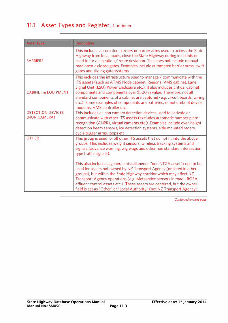
State Highway Database Operations Manual Effective date: 1st January 2014 Manual No.: SM050 Page 11-3
11.1 Asset Types and Register, Continued
Asset Type Description
BARRIERS
This includes automated barriers or barrier arms used to access the State Highway from local roads, close the State Highway during incidents or used to for delineation / route deviation. This does not include manual road open / closed gates. Examples include automated barrier arms, swift gates and sliding gate systems.
CABINET & EQUIPMENT
This includes the infrastructure used to manage / communicate with the ITS assets (such as ATMS Node cabinet, Regional VMS cabinet, Lane Signal Unit (LSU) Power Enclosure etc.). It also includes critical cabinet components and components over $500 in value. Therefore, not all standard components of a cabinet are captured (e.g. circuit boards, wiring etc.). Some examples of components are batteries, remote reboot device, modems, VMS controller etc.
DETECTION DEVICES (NON CAMERA)
This includes all non camera detection devices used to activate or communicate with other ITS assets (excludes automatic number plate recognition (ANPR), virtual cameras etc.). Examples include over-height detection beam sensors, ice detection systems, side mounted radars, cycle trigger arms, loops etc.
OTHER This group is used for all other ITS assets that do not fit into the above groups. This includes weight sensors, wireless tracking systems and signals (advance warning, wig wags and other non standard intersection type traffic signals). This also includes a general miscellaneous “non NTZA asset” code to be used for assets not owned by NZ Transport Agency (or listed in other groups), but within the State Highway corridor which may affect NZ Transport Agency operations (e.g. Metservice sensors in road - ROSA, effluent control assets etc.). These assets are captured, but the owner field is set as “Other” or “Local Authority” (not NZ Transport Agency).
Continued on next page
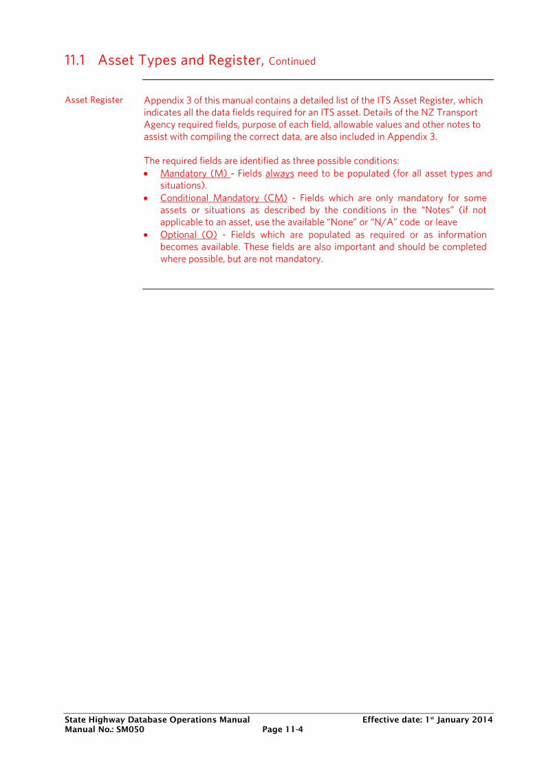
State Highway Database Operations Manual Effective date: 1st January 2014 Manual No.: SM050 Page 11-4
11.1 Asset Types and Register, Continued
Asset Register Appendix 3 of this manual contains a detailed list of the ITS Asset Register, which indicates all the data fields required for an ITS asset. Details of the NZ Transport Agency required fields, purpose of each field, allowable values and other notes to assist with compiling the correct data, are also included in Appendix 3. The required fields are identified as three possible conditions: • Mandatory (M) - Fields always need to be populated (for all asset types and
situations). • Conditional Mandatory (CM) - Fields which are only mandatory for some
assets or situations as described by the conditions in the “Notes” (if not applicable to an asset, use the available “None” or “N/A” code or leave
• Optional (O) - Fields which are populated as required or as information becomes available. These fields are also important and should be completed where possible, but are not mandatory.
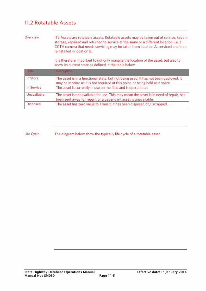
State Highway Database Operations Manual Effective date: 1st January 2014 Manual No.: SM050 Page 11-5
11.2 Rotatable Assets
Overview ITS Assets are rotatable assets. Rotatable assets may be taken out of service, kept in
storage, repaired and returned to service at the same or a different location, i.e. a CCTV camera that needs servicing may be taken from location A, serviced and then reinstalled in location B. It is therefore important to not only manage the location of the asset, but also to know its current state as defined in the table below:
State Description
In Store The asset is in a functional state, but not being used. It has not been deployed. It may be in store as it is not required at this point, or being held as a spare.
In Service The asset is currently in use on the field and is operational.
Unavailable The asset is not available for use. This may mean the asset is in need of repair, has been sent away for repair, or a dependant asset is unavailable.
Disposed The asset has zero value to Transit; it has been disposed of / scrapped.
Life Cycle The diagram below show the typically life cycle of a rotatable asset.
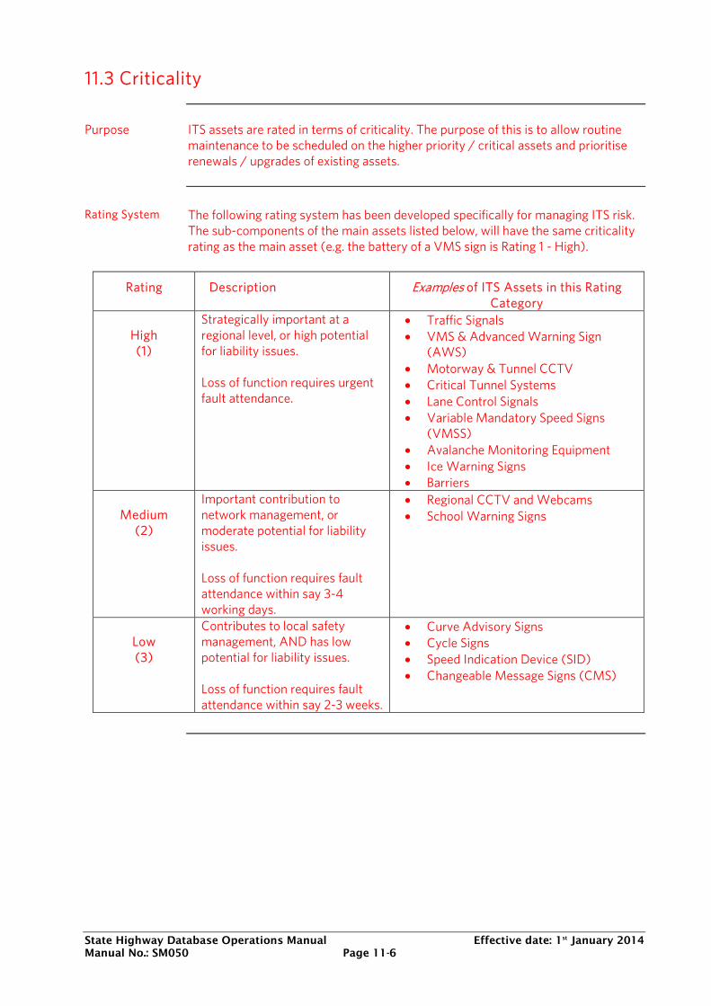
State Highway Database Operations Manual Effective date: 1st January 2014 Manual No.: SM050 Page 11-6
11.3 Criticality
Purpose ITS assets are rated in terms of criticality. The purpose of this is to allow routine
maintenance to be scheduled on the higher priority / critical assets and prioritise renewals / upgrades of existing assets.
Rating System The following rating system has been developed specifically for managing ITS risk. The sub-components of the main assets listed below, will have the same criticality rating as the main asset (e.g. the battery of a VMS sign is Rating 1 - High).
Rating Description Examples of ITS Assets in this Rating Category
High (1)
Strategically important at a regional level, or high potential for liability issues. Loss of function requires urgent fault attendance.
• Traffic Signals • VMS & Advanced Warning Sign
(AWS) • Motorway & Tunnel CCTV • Critical Tunnel Systems • Lane Control Signals • Variable Mandatory Speed Signs
(VMSS) • Avalanche Monitoring Equipment • Ice Warning Signs • Barriers
Medium
(2)
Important contribution to network management, or moderate potential for liability issues. Loss of function requires fault attendance within say 3-4 working days.
• Regional CCTV and Webcams • School Warning Signs
Low (3)
Contributes to local safety management, AND has low potential for liability issues. Loss of function requires fault attendance within say 2-3 weeks.
• Curve Advisory Signs • Cycle Signs • Speed Indication Device (SID) • Changeable Message Signs (CMS)
State Highway Database Operations Manual Effective date: 1st January 2014 Manual No.: SM050 Page 11-7
11.4 Data Capture Process and Responsibility
Process The typical ITS data transfer process is as follows:
ITS data process flow
Responsibility The responsibility for the collection and loading of ITS data is described below in terms of projects and general maintenance: Data Collection and Verification • ITS Projects
o The contractor / consultant responsible for completing the as-built information for the project, is responsible for collating the required ITS data in the correct format. Level 1 certification is required.
Continued on next page
State Highway Database Operations Manual Effective date: 1st January 2014 Manual No.: SM050 Page 11-8
11.4 Data Capture Process and Responsibility, Continued
Responsibility - continued
o The NZ Transport Agency appointed project manager is responsible for ensuring the data is accurate / complete (matches completed works) and has been verified to be in the correct format by a Level 1 certified person. The project Manager is also responsible for the supply of asset data and as-built drawings to the Network Management Consultant (NMC).
• Maintenance & Support: Moves, Additions & Changes (MACs) • The maintenance contractor is responsible for the capture of changes to the
asset base, including spares (in store) and deployed assets. o Data changes are to be communicated to the NZ Transport Agency
appointed Engineer to Contract or Engineers representative within a pre-defined period, by a Level 1 certified person and in the appropriate format (e.g. via an electronic version of the data collection sheet).
• The Engineer is responsible for verifying the data is in the correct format and is accurate / complete (matches completed works / claims) before passing it to the NMC. The Engineer requires Level 1 certification or needs to engage a suitably qualified person to complete the review.
Data processing
The Network Management Consultant (NMC) receives all ITS data updates (as described above). The NMC needs to perform data checking to ensure that data supplied is in the correct format and meets the SHDOM requirements: • Data incomplete or not in the correct format: NMC to send back to the data
provider for rework. • Data is correct and acceptable: Upload into the database by a Level 2 certified
person. • Send an email to the engineer to contract or project manager confirming data
updates have been completed.
All persons involved in collecting or uploading data in the above process will need to be ITS Level 1 (collection and review) or Level 2 certified (upload to the database), to ensure data quality. Individuals completing high level project reviews are not required to be certified, but should ensure the data was collected by a certified person and the information provided matches the project works.
State Highway Database Operations Manual Effective date: 1st January 2014 Manual No.: SM050 Page 11-9
11.5 Activities
Typical activities Updating the ITS table may be due to a variety of activities, resulting in a change to
the asset, such as: New installations: New assets installed as part of Capital or minor projects (where no existing assets are currently installed). The new asset is added to the database with a state of “In Service” or “Unavailable” (not online / activated yet). General Maintenance: The replacement of components in the field or swapping components between asset locations and stores as required in maintaining the operation of existing ITS assets. This will result in a number of possible actions:
• A new asset added to the database with a state of “In Service”. • An existing asset being replaced and the state updated to “Disposed” (if not
repairable) or “Unavailable” (sent for repair). • An asset from the store being deployed into the field and the state updated from
“In Store” to “In Service” with the location details updated to the deployed location.
• Asset components in the field being rotated to more critical locations with failures, which results in a location update for the rotated asset and a state change for the failed asset (“Disposed” or “Unavailable”)
Renewals and upgrades: Replacing assets or upgrading components of active ITS assets as part of a planned forward work plan. This will result in the addition of new assets (“In Service”), as well as the change in location details (swapped to another location or store) and the state of the existing assets to “Disposed” or “In Store” (some usable components). Removal / Disposal: Assets can be removed from the network or disposed of as a result of: • Failed components (not repairable) or obsolete assets being disposed; • Assets removed from a location where it is no longer required and put in store. These assets will be updated with a state of “Disposed” or “In Store”, with the locations updated to the new store location (disposals do not need a location change).
Continued on next page
State Highway Database Operations Manual Effective date: 1st January 2014 Manual No.: SM050 Page 11-10
11.5 Activities, Continued
Typical activities continued
Relocation: Assets or components can be rotated between locations on the network for various reasons. This may include rotating working assets / components in the field from less critical locations to replace failed assets at critical locations. The location details and state could be updated depending on the status of the failing asset. Assets are rotated between the store and the field to allow components to be sent for repair (without returning to a location to re-install a repaired component). This will result in a location update for both assets, as well as a state change to “In Service” (for asset from store) and “Unavailable” or “In Store” (for the asset being repaired). Purchase new stock / existing stock: New assets are purchased as spares and kept in storage. Their location details will be specific to the store location and their state will remain “In Store” until they are deployed onto the network. Existing stock in store may be previously purchased stock or working / repaired assets from the field to be used as spares. Their location details are changed to fit their current location and state will change from “In Service” or “Unavailable” to “In store” and vice versa as they are rotated between the field and the store.
Maintenance Costs
Some activities related to the general maintenance of ITS assets (e.g. graffiti cleaning etc) and the replacement of minor components not captured as an individual ITS asset (e.g. circuit boards, wiring etc.), will not result in an update to any ITS assets captured. These activities are captured as maintenance cost records, in the normal way maintenance activities are recorded for other assets.
Continued on next page
State Highway Database Operations Manual Effective date: 1st January 2014 Manual No.: SM050 Page 11-11
11.5 Activities, Continued
General
If any maintenance or project activities (as described above), results in a change of an asset’s state, location or other details (e.g. maintenance contractor), the ITS table needs to be updated. Maintenance activities may result in assets or components being temporarily removed to be repaired, before being re-installed at the same location. If removal / reinstatement is still current at the time of the data delivery, then the database is updated to reflect the asset as “unavailable”. This will minimise unnecessary repetitive changes to the database, which may not result in a permanent change. If the repair is unsuccessful and the component requires replacement or removal, the database will need to be updated to indicate the replacement of the failed asset / components. Monthly data submission for updates is recommended as best practice to ensure asset data is kept up to date. Assets are never deleted from the database, even if disposed, but are rather managed through updating the state. Assets located in or rotated to the store may be difficult to differentiate and track, as they do not have a unique location. To ensure the correct asset information is captured and updated when rotating assets between the store and the field, it is critical that a unique and visible form of identification is captured for each asset. This may include the visible serial number or a unique name labelled on the asset (noted in the “Field Name” of asset data). A suitable identification system or process needs to be agreed for a maintenance contract before work commences.
Section 12: Maintenance Activities
Database Operations Manual Effective date: Jan 1st 2014 Manual No.: SM050 Page 12-1
12
MAINTENANCE ACTIVITIES
12.0 Introduction
Overview The capture of an electronic data record for each routine maintenance
activity that is undertaken on state highways assets is critical to understand how the asset is performing, and assists in: • Understanding the total cost of ownership of state highway assets; • Quantifying historical repairs, types, faults and locations; • Determining the optimal time to intervene with renewal/replacement
treatments as the cost of maintaining the asset changes; • Monitoring of the application of the maintenance intervention strategy; • Identify assets that are not performing as expected in the forward
works programme, i.e. the extent of failures exceeds what is expected for the remaining asset’s life expectations;
• Cross-checking that the underlying asset registers are being updated correctly, i.e. often where there is a maintenance activity record there should be a corresponding change to the asset register record, and vice versa, such as work carried out on signs and culverts.
Historical maintenance activities are important inputs into justification of major treatments, such as surfacing and pavement renewal treatments and as an input for tenderers on maintenance contracts to understand historical network performance.
In this Section The topics in this section are listed below:
Topic See Page
12.1 Overview of Process 40 12.2 Delivery Requirements 41
Section 12: Maintenance Activities
Database Operations Manual Effective date: Jan 1st 2014 Manual No.: SM050 Page 12-2
12.1 Overview of Process
Data delivery Maintenance activity data will be loaded into the maintenance cost module of the
NZTA asset information management system, currently being the RAMM database, in accordance with the contract document deliverable requirements. The maintenance cost module for RAMM is designed to accept data from as many source formats as possible. The most likely source of maintenance activity data is an electronic download from a contractor’s maintenance management system following the appropriate quality checks.
Maintenance Cost Module
It is assumed that contractors will already be using a maintenance management system. For this reason the Maintenance Costs module is not designed to replace a contractor’s maintenance management system. The purposes of the maintenance cost module are to: • Allow input from different cost/activity recording systems • Convert maintenance costs from a variety of suppliers to consistent terms • Provide a repository of historical maintenance achievement for data analysis.
Training and Support
Please refer to RAMM Software Ltd for training and their online RAMM User Guide.
Definitions The following terminology is used to describe the delivery process:
Maintenance Activity Data Source, this is the raw data loaded from the contractor’s maintenance management system. Maintenance Cost Table, this is the converted data. This associates the location of the repair to the appropriate carriageway section. Maintenance Cost Batch, unique identifier for each loading session. Producer Statement, this is a statement within the contractor’s monthly report, confirming that the quantities of work being delivered to NZTA’s asset information system represent the actual quantities of work carried out on the network.
Section 12: Maintenance Activities
Database Operations Manual Effective date: Jan 1st 2014 Manual No.: SM050 Page 12-3
12.2 Delivery Requirements
Data requirements
This document is to be used in conjunction with Appendix 4: Maintenance Activities, which details the specific coding structures for the data. In 2013 two significant changes to the data requirements of maintenance activities occurred: Standardised units of measures, Appendix 4: Maintenance Activities prescribes for each activity what the required unit of measure is to be captured in the contractor’s maintenance management system and delivered to NZTA, Quantity based data. The quantity of the maintenance activity is important as it is the primary element for analysis which is not affected by commercial or risk based pricing influences. The unit cost attributed to each activity shall be agreed with NZTA.
Importing Process
The following steps are an overview of the process to load maintenance activity data into the Maintenance Cost Module in NZTA’s asset information management system:
Step Action 1 The contractor unloads the data from the maintenance activity
data source. 2 Ensure that the data is correct, i.e. locations, dimensions of
activity, rate, units of measure and codes are in accordance with Appendix 4: Maintenance Activities.
3 Create a maintenance cost batch header in RAMM Manager detailing the period that the maintenance activity data represents.
4 Import maintenance activity data into the maintenance cost table via RAMM Manager’s import wizard, validating and ensuring no errors.
5 Print summary report from RAMM Manager and include as part of the contract monthly report producer statement.
Producer Statement
The contractor will provide a producer statement indicating that the maintenance activity monthly deliverable represents the actual quantities of work carried out on the network. The producer statement is confirmation by the contractor that they have carried out the maintenance activities in accordance with the contract specifications. Work covered by this statement should have been supervised and checked by suitably qualified persons as per the Quality Management Plan.

Section 12: Maintenance Activities
Database Operations Manual Effective date: Jan 1st 2014 Manual No.: SM050 Page 12-4