Embed Size (px)
Citation preview
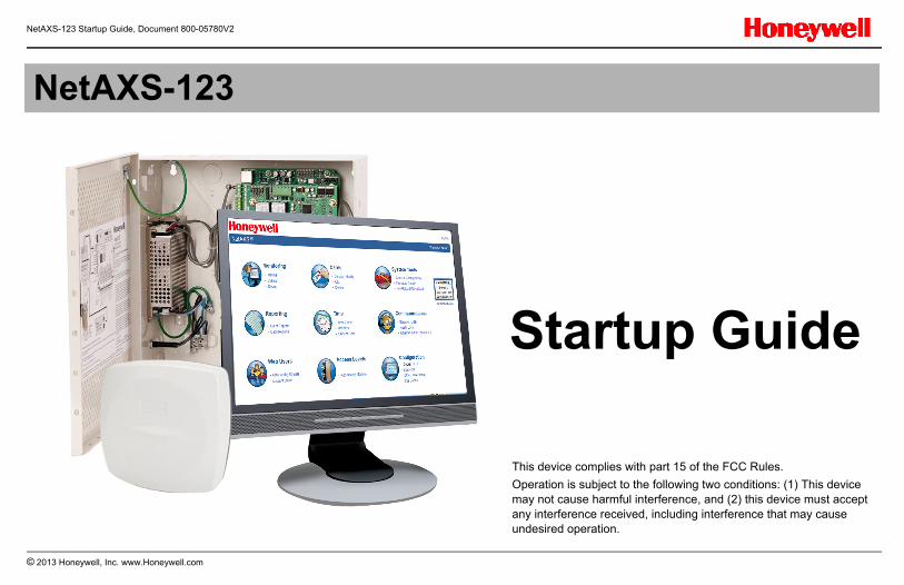
NetAXS-123 Startup Guide, Document 800-05780V2
© 2013 Honeywell, Inc. www.Honeywell.com 1
NetAXS-123
Startup Guide
This device complies with part 15 of the FCC Rules.
Operation is subject to the following two conditions: (1) This device may not cause harmful interference, and (2) this device must accept any interference received, including interference that may cause undesired operation.
DC OUT
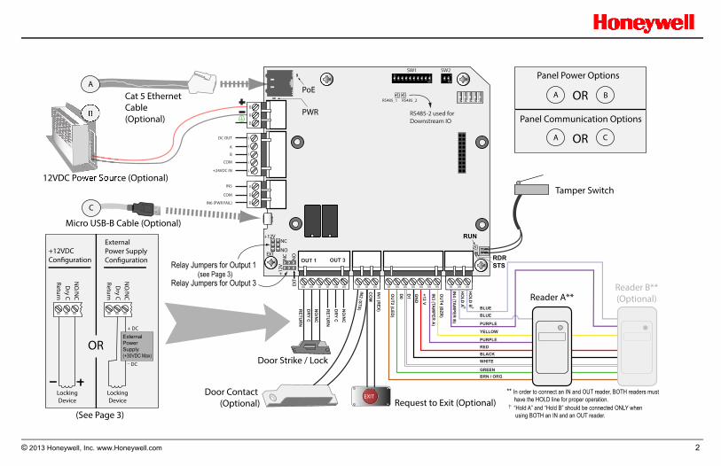
A
B
COM
+24VDC IN
IN5
COM
IN6 (PWR FAIL)
HO
LD B
HO
LD A
BLUE
BRN / ORGGREEN
WHITEBLACKREDPURPLE
PURPLE
BLUE
YELLOW
IN4 (TA
MPER
B)
OU
T4 (BZR
)
IN3 (TA
MPER
A)
+12 V
GN
D
D1
D0
OU
T2 (LED)
IN1 (R
EX)
CO
M
IN2 (STS)N
O/N
C
DRY C
RETU
RN
NO
/NC
DRY C
RETU
RN
NO
110
NO
1
RS485-2 used for Downstream IO
SW2SW1
RS485_1 RS485_2
OUT 1 OUT 3
EXITDoor Contact (Optional)
+12V
+12V
EXT
EXT
NC
NC
NO
NO
Door Strike / Lock
Cat 5 Ethernet Cable(Optional)
Request to Exit (Optional)
Tamper Switch12VDC Power Source (Optional)
Relay Jumpers for Output 1(see Page 3)
Relay Jumpers for Output 3
(See Page 3)
Micro USB-B Cable (Optional)
A
B
C
A
A
B
C
OR
OR
Panel Power Options
Panel Communication Options
Reader A**Reader B**(Optional)
PoE
PWR
RUN
RDRSTS
ReturnD
ry CN
O/N
C
Locking Device
ReturnD
ry CN
O/N
C
Locking Device
External Power Supply (+30VDC Max)
+ DC
DC
OR
+12VDC Configuration
External Power Supply Configuration
** In order to connect an IN and OUT reader, BOTH readers must have the HOLD line for proper operation.
“Hold A” and “Hold B” should be connected ONLY when using BOTH an IN and an OUT reader.
© 2013 Honeywell, Inc. www.Honeywell.com 2
NetAXS-123 Startup Guide, Document 800-05780V2
TABLE OF CONTENTS1) Introduction ............................................................................................ 32) Before You Start ..................................................................................... 33) Device Connection Order ....................................................................... 44) Powering Up ........................................................................................... 45) Connecting to the Web Server ............................................................... 56) Logging In to the System ....................................................................... 77) System Configuration ............................................................................. 8APPENDIX A) Adding a Panel ................................................................. 14APPENDIX B) Adding a User ................................................................... 15APPENDIX C) Changing the Ethernet Default IP Address ...................... 16APPENDIX D) Enabling the In and Out Readers ..................................... 16APPENDIX E) Additional Features ........................................................... 17APPENDIX F) Monitoring Status............................................................... 20APPENDIX G) Adding Additional Doors ................................................... 22APPENDIX H) Resetting the Panel .......................................................... 22
1) IntroductionThis document describes the basic setup, wiring and configuration steps needed for the NetAXS-123 access control system.
NetAXS-123 can be configured in many different ways, depending on the specific needs of the end-users. This document covers a single panel, 1 door system. Additional doors are set up, wired and configured in a similar manner to the first door. This document does not cover all of these configurations.
For further configuration and setup information including installations related to WIN-PAK and/or RS-485 communications please consult the NetAXS-123 User Guide and NetAXS-123 Installation Guide; both on NetAXS-123 Product CD.
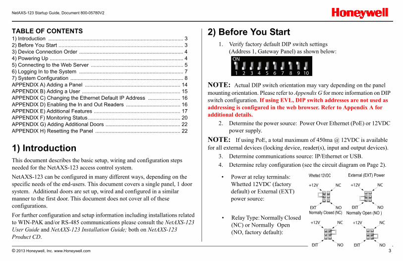
2) Before You Start1. Verify factory default DIP switch settings
(Address 1, Gateway Panel) as shown below:
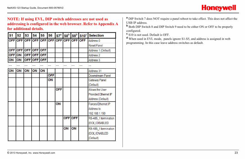
NOTE: Actual DIP switch orientation may vary depending on the panel mounting orientation. Please refer to Appendix G for more information on DIP switch configuration. If using EVL, DIP switch addresses are not used as addressing is configured in the web browser. Refer to Appendix A for additional details.
2. Determine the power source: Power Over Ethernet (PoE) or 12VDC power supply.
NOTE: If using PoE, a total maximum of 450ma @ 12VDC is available for all external devices (locking device, reader(s), input and output devices).
3. Determine communications source: IP/Ethernet or USB.
4. Determine relay configuration (see the circuit diagram on Page 2).
NO
1 2 3 4 5 6 7 8 9 10
+12V NC
EXT NO
+12V NC
EXT NO
Whetted 12VDC External (EXT) Power • Power at relay terminals: Whetted 12VDC (factory default) or External (EXT) power source:
• Relay Type: Normally Closed (NC) or Normally Open (NO, factory default):
+12V NC
EXT NO
+12V NC
EXT NO
Normally Open (NO )Normally Closed (NC)
© 2013 Honeywell, Inc. www.Honeywell.com 3
NetAXS-123 Startup Guide, Document 800-05780V2
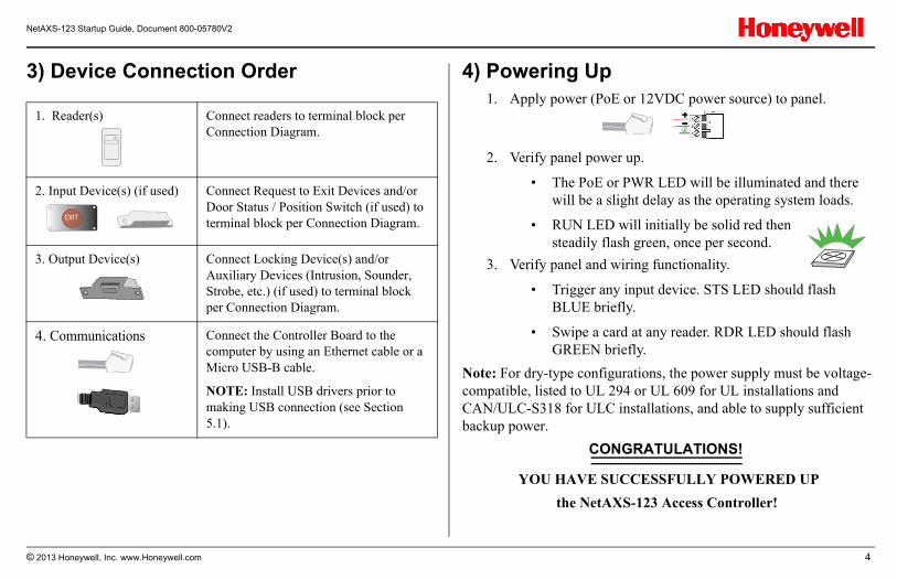
3) Device Connection Order 4) Powering Up1. Apply power (PoE or 12VDC power source) to panel.
2. Verify panel power up.
• The PoE or PWR LED will be illuminated and there will be a slight delay as the operating system loads.
• RUN LED will initially be solid red then steadily flash green, once per second.
3. Verify panel and wiring functionality.
• Trigger any input device. STS LED should flash BLUE briefly.
• Swipe a card at any reader. RDR LED should flash GREEN briefly.
Note: For dry-type configurations, the power supply must be voltage-compatible, listed to UL 294 or UL 609 for UL installations and CAN/ULC-S318 for ULC installations, and able to supply sufficient backup power.
YOU HAVE SUCCESSFULLY POWERED UP
the NetAXS-123 Access Controller!
1. Reader(s) Connect readers to terminal block per Connection Diagram.
2. Input Device(s) (if used) Connect Request to Exit Devices and/or Door Status / Position Switch (if used) to terminal block per Connection Diagram.
3. Output Device(s) Connect Locking Device(s) and/or Auxiliary Devices (Intrusion, Sounder, Strobe, etc.) (if used) to terminal block per Connection Diagram.
4. Communications Connect the Controller Board to the computer by using an Ethernet cable or a Micro USB-B cable.
NOTE: Install USB drivers prior to making USB connection (see Section 5.1).
EXIT
CONGRATULATIONS!
© 2013 Honeywell, Inc. www.Honeywell.com 4
NetAXS-123 Startup Guide, Document 800-05780V2
5) Connecting to the Web Server This section describes two configurations for connecting a computer to the NetAXS-123 web server:
• Connecting via USB port.
• Connecting via Ethernet port.
NOTE: The panel that you are connecting to the computer is the Gateway panel. DIP switch 6 on a Gateway panel must be set to ON for a successful connection.
5.1 Connecting via USB Port
Warning: Do NOT connect the USB cable to the panel until AFTER the drivers are installed.
Follow these steps to set up the NetAXS-123 USB connection. (This procedure should be performed only once.)
1. Insert the NetAXS-123 Product CD into your Windows-based computer. The NetAXS-123 product menu opens in the web browser.
Note: If the product menu does not open automatically in your browser, right click on the Start button and select Explore. In the folder tree, find and click the CD drive that is reading the NetAXS-123 Product CD.
2. Click Install USB Drivers on the product menu to start the USB driver installation wizard.
3. Click Next to display the Ready to Install the Program screen.
© 2013 Honeywell, Inc. www.Honeywell.com 5
NetAXS-123 Startup Guide, Document 800-05780V2
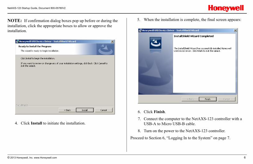
NOTE: If confirmation dialog boxes pop up before or during the installation, click the appropriate boxes to allow or approve the installation.
4. Click Install to initiate the installation.
5. When the installation is complete, the final screen appears:
6. Click Finish.
7. Connect the computer to the NetAXS-123 controller with a USB-A to Micro USB-B cable.
8. Turn on the power to the NetAXS-123 controller.
Proceed to Section 6, “Logging In to the System” on page 7.
© 2013 Honeywell, Inc. www.Honeywell.com 6
NetAXS-123 Startup Guide, Document 800-05780V2
5.2 Connecting via Ethernet Port
You can connect the NetAXS-123 panel to a PC either directly with a standard or cross-over ethernet cable as well as through an ethernet switch with standard ethernet patch cables.
Perform the following steps:
1. In order to connect to the NetAXS-123 for the first time, configure the computer's network connection:
a. Select Start > Settings > Control Panel.
b. Click Network and Dial-up Connections.
c. Identify your local Ethernet connection (commonly labeled Local Area Connection), and right-click the icon to display the Local Area Connection Properties screen.
d. Highlight the Internet Protocol (TCP/IP) connection.
e. Click Properties to display your system’s current Internet Protocol properties.
Important: Keep a record of your computer’s current network configuration as it appears in this screen. You will need to re-instate this configuration later.
f. Select "Use the following IP address."
g. Enter "192.168.1.10" in the IP address field.
h. Enter "255.255.255.0" in the Subnet mask field.
i. Click OK to accept the entries.
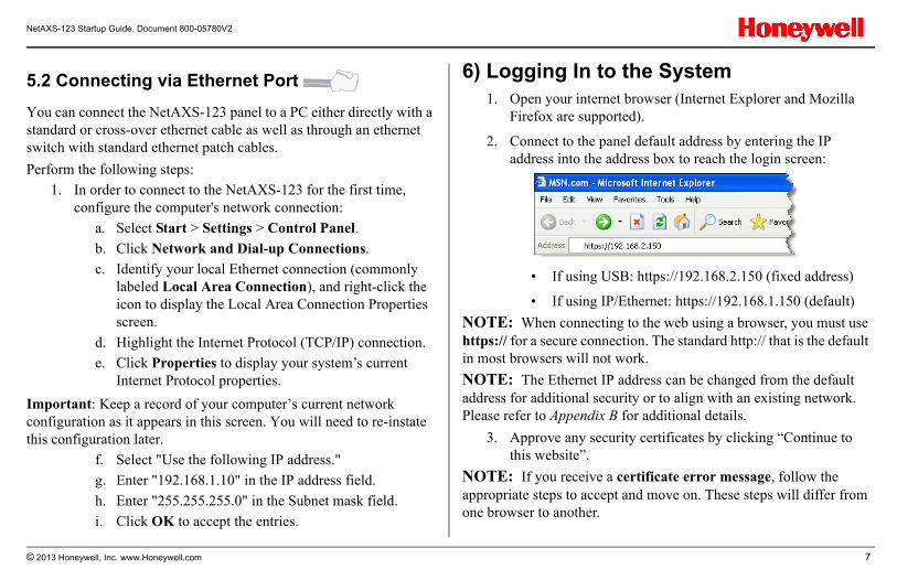
6) Logging In to the System1. Open your internet browser (Internet Explorer and Mozilla
Firefox are supported).
2. Connect to the panel default address by entering the IP address into the address box to reach the login screen:
• If using USB: https://192.168.2.150 (fixed address)
• If using IP/Ethernet: https://192.168.1.150 (default)
NOTE: When connecting to the web using a browser, you must use https:// for a secure connection. The standard http:// that is the default in most browsers will not work.
NOTE: The Ethernet IP address can be changed from the default address for additional security or to align with an existing network. Please refer to Appendix B for additional details.
3. Approve any security certificates by clicking “Continue to this website”.
NOTE: If you receive a certificate error message, follow the appropriate steps to accept and move on. These steps will differ from one browser to another.
© 2013 Honeywell, Inc. www.Honeywell.com 7
NetAXS-123 Startup Guide, Document 800-05780V2
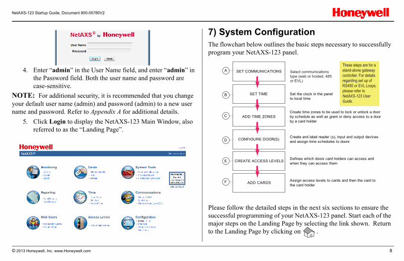
4. Enter “admin” in the User Name field, and enter “admin” in the Password field. Both the user name and password are case-sensitive.
NOTE: For additional security, it is recommended that you change your default user name (admin) and password (admin) to a new user name and password. Refer to Appendix A for additional details.
5. Click Login to display the NetAXS-123 Main Window, also referred to as the “Landing Page”.
7) System ConfigurationThe flowchart below outlines the basic steps necessary to successfully program your NetAXS-123 panel.
Please follow the detailed steps in the next six sections to ensure the successful programming of your NetAXS-123 panel. Start each of the major steps on the Landing Page by selecting the link shown. Return to the Landing Page by clicking on .
A SET COMMUNICATIONS
CONFIGURE DOOR(S)
ADD TIME ZONES
SET TIME
CREATE ACCESS LEVELS
ADD CARDS
E
D
C
B
F
Set the clock in the panel to local time
Create and label reader (s), input and output devices and assign time schedules to doors
Assign access levels to cards and then the card to the card holder
Create time zones to be used to lock or unlock a door by schedule as well as grant or deny access to a door by a card holder
Defines which doors card holders can access and when they can access them
Select communications type (web or hosted, 485 or EVL)
These steps are for a stand-alone gateway controller. For details regarding set up of RS485 or EVL Loops, please refer to NetAXS-123 User Guide.
© 2013 Honeywell, Inc. www.Honeywell.com 8
NetAXS-123 Startup Guide, Document 800-05780V2
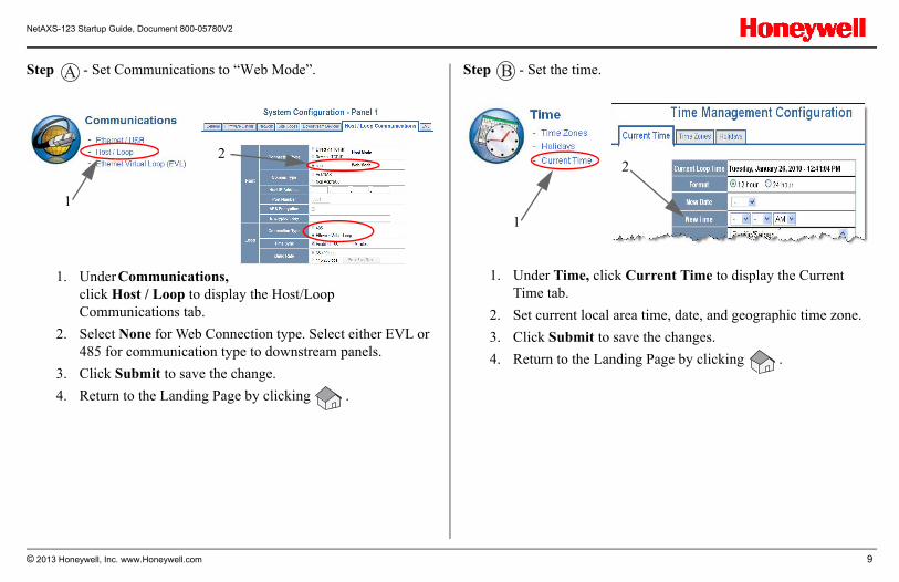
Step - Set Communications to “Web Mode”. Step - Set the time.A
1. Under Communications, click Host / Loop to display the Host/Loop Communications tab.
2. Select None for Web Connection type. Select either EVL or 485 for communication type to downstream panels.
3. Click Submit to save the change.
4. Return to the Landing Page by clicking .
1
2
B
1. Under Time, click Current Time to display the Current Time tab.
2. Set current local area time, date, and geographic time zone.
3. Click Submit to save the changes.
4. Return to the Landing Page by clicking .
1
2
© 2013 Honeywell, Inc. www.Honeywell.com 9
NetAXS-123 Startup Guide, Document 800-05780V2
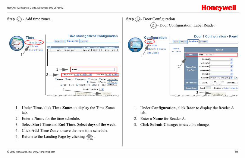
Step - Add time zones. Step - Door Configuration
- Door Configuration: Label Reader
C
1. Under Time, click Time Zones to display the Time Zones tab.
2. Enter a Name for the time schedule.
3. Select Start Time and End Time. Select days of the week.
4. Click Add Time Zone to save the new time schedule.
5. Return to the Landing Page by clicking .
6
1
23
4
DD1
1. Under Configuration, click Door to display the Reader A tab.
2. Enter a Name for Reader A.
3. Click Submit Changes to save the change.
1
2
3
© 2013 Honeywell, Inc. www.Honeywell.com 10
NetAXS-123 Startup Guide, Document 800-05780V2
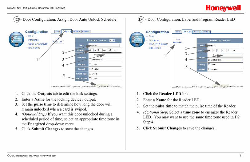
- Door Configuration: Assign Door Auto Unlock Schedule - Door Configuration: Label and Program Reader LEDD2
1. Click the Outputs tab to edit the lock settings.
2. Enter a Name for the locking device / output.3. Set the pulse time to determine how long the door will
remain unlocked when a card is swiped.4. (Optional Step) If you want this door unlocked during a
scheduled period of time, select an appropriate time zone in the Energized drop-down menu.
5. Click Submit Changes to save the changes.
1
2
3
4
5
D3
1. Click the Reader LED link.
2. Enter a Name for the Reader LED.
3. Set the pulse time to match the pulse time of the Reader.
4. (Optional Step) Select a time zone to energize the Reader LED. You may want to use the same time zone used in D2 Step 4.
5. Click Submit Changes to save the changes.
1
23
4
5
© 2013 Honeywell, Inc. www.Honeywell.com 11
NetAXS-123 Startup Guide, Document 800-05780V2
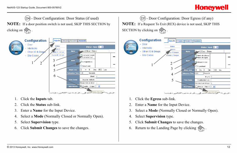
- Door Configuration: Door Status (if used)
NOTE: If a door position switch is not used, SKIP THIS SECTION by
clicking on .
- Door Configuration: Door Egress (if any)
NOTE: If a Request To Exit (REX) device is not used, SKIP THIS
SECTION by clicking on .
D4
1. Click the Inputs tab.
2. Click the Status sub-link.
3. Enter a Name for the Input Device.
4. Select a Mode (Normally Closed or Normally Open).
5. Select Supervision type.
6. Click Submit Changes to save the changes.
31 2
456
D5
1. Click the Egress sub-link.
2. Enter a Name for the Input Device.
3. Select a Mode (Normally Closed or Normally Open).
4. Select Supervision type.
5. Click Submit Changes to save the changes.
6. Return to the Landing Page by clicking .
213
4
5
© 2013 Honeywell, Inc. www.Honeywell.com 12
NetAXS-123 Startup Guide, Document 800-05780V2
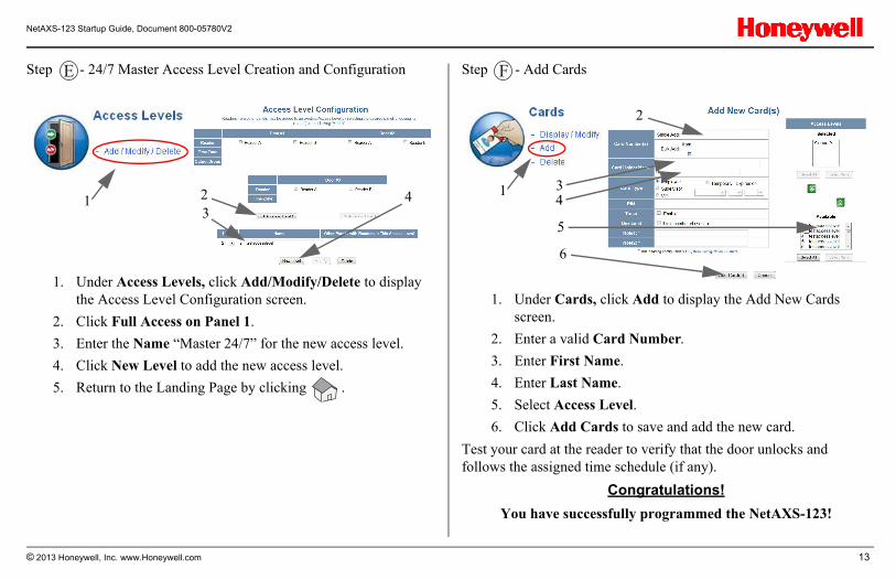
Step - 24/7 Master Access Level Creation and Configuration Step - Add Cards
Test your card at the reader to verify that the door unlocks and follows the assigned time schedule (if any).
Congratulations!
You have successfully programmed the NetAXS-123!
E
1. Under Access Levels, click Add/Modify/Delete to display the Access Level Configuration screen.
2. Click Full Access on Panel 1.
3. Enter the Name “Master 24/7” for the new access level.
4. Click New Level to add the new access level.
5. Return to the Landing Page by clicking .
1 23
4
F
1. Under Cards, click Add to display the Add New Cards screen.
2. Enter a valid Card Number.
3. Enter First Name.
4. Enter Last Name.
5. Select Access Level.
6. Click Add Cards to save and add the new card.
1
2
34
5
6
© 2013 Honeywell, Inc. www.Honeywell.com 13
NetAXS-123 Startup Guide, Document 800-05780V2
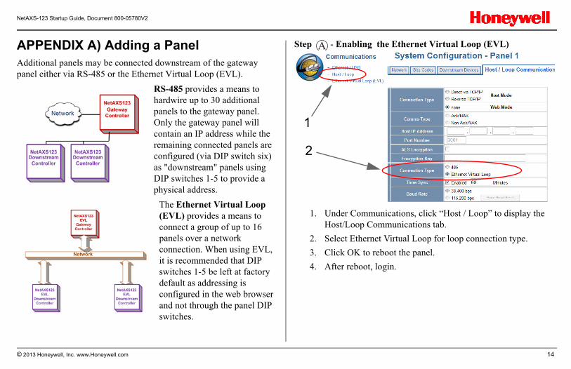
APPENDIX A) Adding a PanelAdditional panels may be connected downstream of the gateway panel either via RS-485 or the Ethernet Virtual Loop (EVL).
RS-485 provides a means to hardwire up to 30 additional panels to the gateway panel. Only the gateway panel will contain an IP address while the remaining connected panels are configured (via DIP switch six) as "downstream" panels using DIP switches 1-5 to provide a physical address.
The Ethernet Virtual Loop (EVL) provides a means to connect a group of up to 16 panels over a network connection. When using EVL, it is recommended that DIP switches 1-5 be left at factory default as addressing is configured in the web browser and not through the panel DIP switches.
Step - Enabling the Ethernet Virtual Loop (EVL)
1. Under Communications, click “Host / Loop” to display the Host/Loop Communications tab.
2. Select Ethernet Virtual Loop for loop connection type.
3. Click OK to reboot the panel.
4. After reboot, login.
A
2
1
© 2013 Honeywell, Inc. www.Honeywell.com 14
NetAXS-123 Startup Guide, Document 800-05780V2
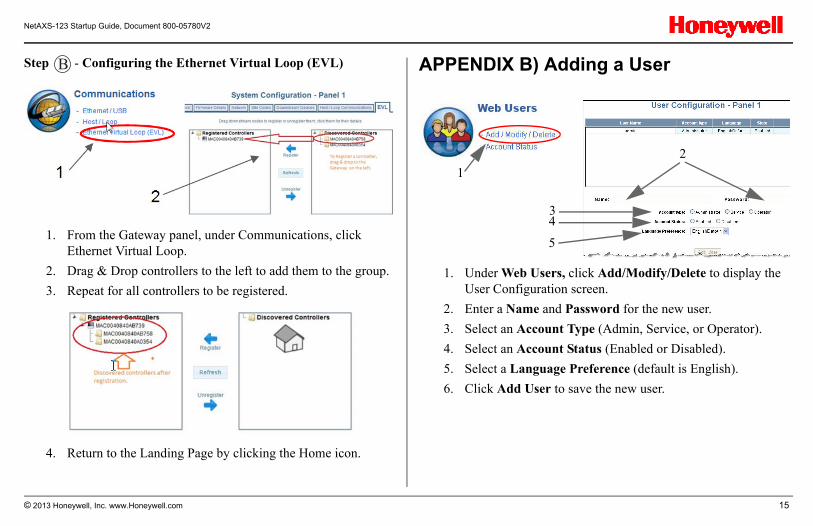
Step - Configuring the Ethernet Virtual Loop (EVL)
1. From the Gateway panel, under Communications, click Ethernet Virtual Loop.
2. Drag & Drop controllers to the left to add them to the group.
3. Repeat for all controllers to be registered.
4. Return to the Landing Page by clicking the Home icon.
APPENDIX B) Adding a UserB
1. Under Web Users, click Add/Modify/Delete to display the User Configuration screen.
2. Enter a Name and Password for the new user.
3. Select an Account Type (Admin, Service, or Operator).
4. Select an Account Status (Enabled or Disabled).
5. Select a Language Preference (default is English).
6. Click Add User to save the new user.
1
2
34
5
© 2013 Honeywell, Inc. www.Honeywell.com 15
NetAXS-123 Startup Guide, Document 800-05780V2
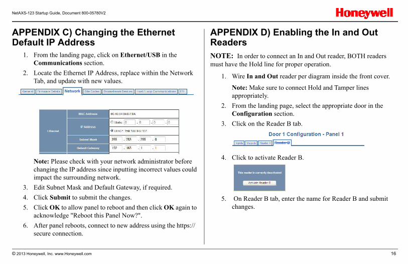
APPENDIX C) Changing the Ethernet Default IP Address
1. From the landing page, click on Ethernet/USB in the Communications section.
2. Locate the Ethernet IP Address, replace within the Network Tab, and update with new values.
Note: Please check with your network administrator before changing the IP address since inputting incorrect values could impact the surrounding network.
3. Edit Subnet Mask and Default Gateway, if required.
4. Click Submit to submit the changes.
5. Click OK to allow panel to reboot and then click OK again to acknowledge "Reboot this Panel Now?".
6. After panel reboots, connect to new address using the https:// secure connection.
APPENDIX D) Enabling the In and Out Readers NOTE: In order to connect an In and Out reader, BOTH readers must have the Hold line for proper operation.
1. Wire In and Out reader per diagram inside the front cover.
Note: Make sure to connect Hold and Tamper lines appropriately.
2. From the landing page, select the appropriate door in the Configuration section.
3. Click on the Reader B tab.
4. Click to activate Reader B.
5. On Reader B tab, enter the name for Reader B and submit changes.
© 2013 Honeywell, Inc. www.Honeywell.com 16
NetAXS-123 Startup Guide, Document 800-05780V2
APPENDIX E) Additional FeaturesThe following section provides a brief description of additional features contained within the NetAXS-123 system. For further details on set-up and use of each feature, please refer to the NetAXS-123 Resource CD or NetAXS-123 User Guide, # 800-05168.
Card Import
The NetAXS-123 has the ability to import a data file that contains card holder information to assist in quickly adding card holders information to the panel.
Database Backup
The NetAXS-123 allows you to save a backup file of each panel on your PC for safe keeping.
Deleting Cards
Cards may be deleted either by number, a range of numbers or by Card Holder Last Name.
Groups
NetAXS-123 supports output groups which are most commonly used for elevator control.
Downstream IO Devices
NetAXS-123 now supports auxiliary Input and Output Devices (NX4IN and NX4OUT boards). Refer to the installation and user guides for details on wiring and configuration details.
Ethernet Virtual Loop (EVL)
Ethernet Virtual Loop feature allows multiple IP Network connected controllers to be managed from a single IP Address.
Holidays
Holidays are special days that take precedence over a standard day. Holidays are most often used for a day when no work is scheduled at the facility, employees are not to have premises access and the doors are to remained locked.
Reports
Events Reports: Allows generation of card event reports by last name and card number.
Card Reports: Allows the ability to view cards and card data by last name as well as card number.
© 2013 Honeywell, Inc. www.Honeywell.com 17
NetAXS-123 Startup Guide, Document 800-05780V2
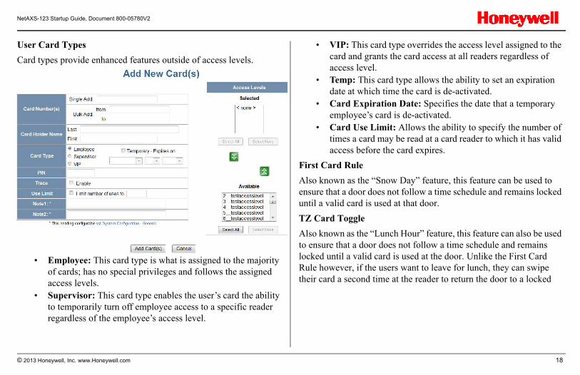
User Card Types
Card types provide enhanced features outside of access levels.
• Employee: This card type is what is assigned to the majority of cards; has no special privileges and follows the assigned access levels.
• Supervisor: This card type enables the user’s card the ability to temporarily turn off employee access to a specific reader regardless of the employee’s access level.
• VIP: This card type overrides the access level assigned to the card and grants the card access at all readers regardless of access level.
• Temp: This card type allows the ability to set an expiration date at which time the card is de-activated.
• Card Expiration Date: Specifies the date that a temporary employee’s card is de-activated.
• Card Use Limit: Allows the ability to specify the number of times a card may be read at a card reader to which it has valid access before the card expires.
First Card Rule
Also known as the “Snow Day” feature, this feature can be used to ensure that a door does not follow a time schedule and remains locked until a valid card is used at that door.
TZ Card Toggle
Also known as the “Lunch Hour” feature, this feature can also be used to ensure that a door does not follow a time schedule and remains locked until a valid card is used at the door. Unlike the First Card Rule however, if the users want to leave for lunch, they can swipe their card a second time at the reader to return the door to a locked
© 2013 Honeywell, Inc. www.Honeywell.com 18
NetAXS-123 Startup Guide, Document 800-05780V2
state. After lunch, the users can then present their card to the reader again and the door returns to following the assigned time schedule.
Both TZ Card Toggle and First Card Rule cannot be enabled at the same time.
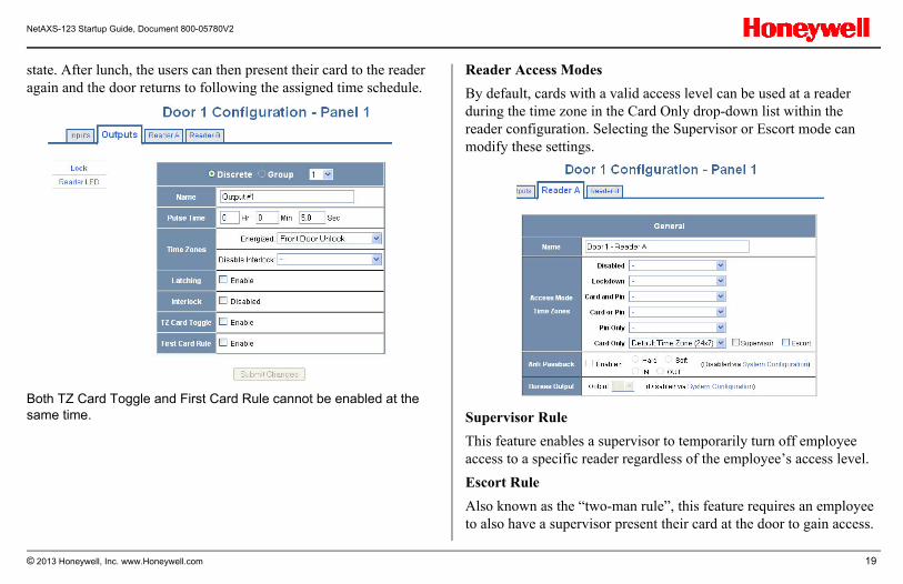
Reader Access Modes
By default, cards with a valid access level can be used at a reader during the time zone in the Card Only drop-down list within the reader configuration. Selecting the Supervisor or Escort mode can modify these settings.
Supervisor Rule
This feature enables a supervisor to temporarily turn off employee access to a specific reader regardless of the employee’s access level.
Escort Rule
Also known as the “two-man rule”, this feature requires an employee to also have a supervisor present their card at the door to gain access.
© 2013 Honeywell, Inc. www.Honeywell.com 19
NetAXS-123 Startup Guide, Document 800-05780V2
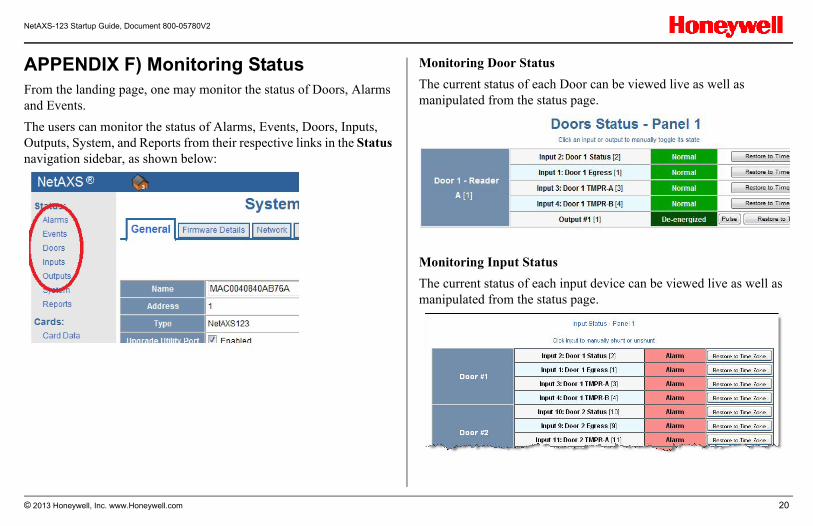
APPENDIX F) Monitoring StatusFrom the landing page, one may monitor the status of Doors, Alarms and Events.
The users can monitor the status of Alarms, Events, Doors, Inputs, Outputs, System, and Reports from their respective links in the Status navigation sidebar, as shown below:
Monitoring Door Status
The current status of each Door can be viewed live as well as manipulated from the status page.
Monitoring Input Status
The current status of each input device can be viewed live as well as manipulated from the status page.
© 2013 Honeywell, Inc. www.Honeywell.com 20
NetAXS-123 Startup Guide, Document 800-05780V2
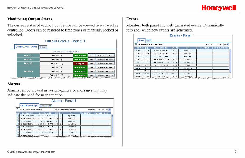
Monitoring Output Status
The current status of each output device can be viewed live as well as controlled. Doors can be restored to time zones or manually locked or unlocked.
Alarms
Alarms can be viewed as system-generated messages that may indicate the need for user attention.
Events
Monitors both panel and web-generated events. Dynamically refreshes when new events are generated.
© 2013 Honeywell, Inc. www.Honeywell.com 21
NetAXS-123 Startup Guide, Document 800-05780V2
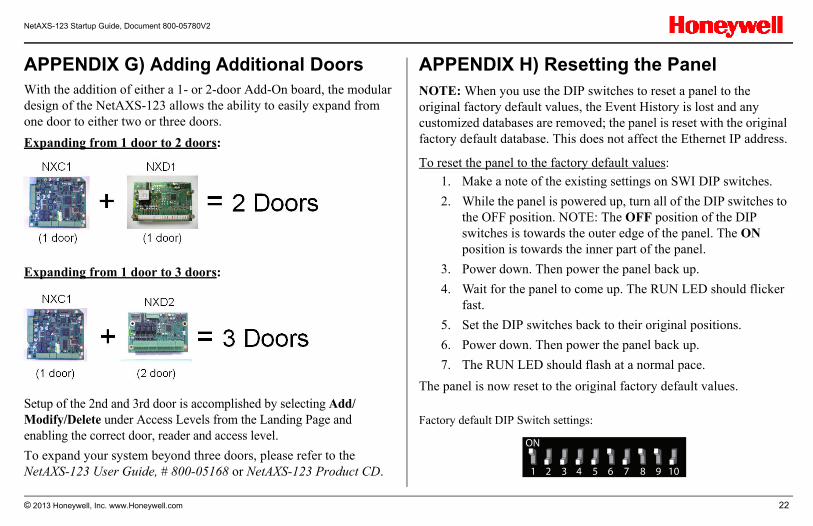
APPENDIX G) Adding Additional DoorsWith the addition of either a 1- or 2-door Add-On board, the modular design of the NetAXS-123 allows the ability to easily expand from one door to either two or three doors.
Expanding from 1 door to 2 doors:
Expanding from 1 door to 3 doors:
Setup of the 2nd and 3rd door is accomplished by selecting Add/Modify/Delete under Access Levels from the Landing Page and enabling the correct door, reader and access level.
To expand your system beyond three doors, please refer to the NetAXS-123 User Guide, # 800-05168 or NetAXS-123 Product CD.
APPENDIX H) Resetting the PanelNOTE: When you use the DIP switches to reset a panel to the original factory default values, the Event History is lost and any customized databases are removed; the panel is reset with the original factory default database. This does not affect the Ethernet IP address.
To reset the panel to the factory default values:
1. Make a note of the existing settings on SWI DIP switches.
2. While the panel is powered up, turn all of the DIP switches to the OFF position. NOTE: The OFF position of the DIP switches is towards the outer edge of the panel. The ON position is towards the inner part of the panel.
3. Power down. Then power the panel back up.
4. Wait for the panel to come up. The RUN LED should flicker fast.
5. Set the DIP switches back to their original positions.
6. Power down. Then power the panel back up.
7. The RUN LED should flash at a normal pace.
The panel is now reset to the original factory default values.
Factory default DIP Switch settings:
NO
1 2 3 4 5 6 7 8 9 10
© 2013 Honeywell, Inc. www.Honeywell.com 22
NetAXS-123 Startup Guide, Document 800-05780V2
NOTE: If using EVL, DIP switch addresses are not used as addressing is configured in the web browser. Refer to Appendix A for additional details.
a DIP Switch 7 does NOT require a panel reboot to take effect. This does not affect the USB IP address.b Both DIP Switch 8 and DIP Switch 9 need to be either ON or OFF to be properly configured.c S10 is not used. Default is OFF.d When used in EVL mode, panels ignore S1-S5, and address is assigned in web programming. In this case leave address switches as default.
© 2013 Honeywell, Inc. www.Honeywell.com 23
NetAXS-123 Startup Guide, Document 800-05780V2
Technical SupportNeed Support? We’re Always There For Our Customers!
Contact Technical Support before, during or after a system installation whenever troubleshooting or programming assistance is needed.
Call 1-800-323-4576, Option 2 Email: [email protected] (For North America Authorized Dealers only)
After Hours? Check out our website:https://www.honeywellaccess.com/contact/tech/index.html
Technical Support ServicesHoneywell Access Systems' technical support group is available to assist Honeywell dealers with issues they may encounter with Honeywell Systems Group hardware and software during system installation.
Product MatrixFind product information including datasheets, manuals, images, drawings, A & E Specs and other information.
Download CenterExisting customers get valuable software upgrade information.
Technical FAQsRead frequently asked questions ranging from the basic to the unique along with product bulletins.
Document 800-05780V2
August 2013
© Honeywell International, All Rights Reserved
Specifications subject to change without notice
For more information see NetAXS-123 Resource CD
Technical support : 1-800-323-4576, Option 2
Honeywell Access Systems
2700 Blankenbaker Pkwy, Suite 150, Louisville, KY 40299 | 1-800-223-9436
© 2013 Honeywell, Inc. www.Honeywell.com 24