Embed Size (px)
Citation preview
Starting Lockout Functionin TDM Servo Drive Modules
DOK-ANAX**-TDM*ANL*FKT-ANW1-EN-P
Applications manual
mannesmannRexroth
engineering
Indramat258241
2 TDM Starting Lockout • 9.555.012.4-05 •4/94 •
Title:
Type of Documentation:
Doc. No.:
Internal File Ref.:
Replaces:
The purposeof this document
Copyright:
Validity:
Copying of this document, and giving it to others and the use orcommunication of the contents thereof without express authority areforbidden. Offenders are liable to the payment of damages. All rightsare reserved in the event of the grant of a patent or the registrationof a utility model or design.
We reserve the right to make changes to the documents and inproduct delivery.
About this Documentation
Starting Lockout Function in TDM Servo Drive Modules
Application Manual
9.555.012.4-05 EN / 4/94
File No. 4 / •startinglockout TDM EN
9.555.012.4-03 DE / 3/93
This document serves:
– to define possible application and operating conditions
– to assist in project planning and installation
– the commissioning and monitoring of the starting lockout function
3• TDM Starting Lockout • 9.555.012.4-05 • 4/94
Please note the guidelines outlined in Section 3 prior tocommissioning the starting lockout!
Table of Contents
Table of Contents Page
1. Possible applications of the starting lockout 7
1.1. A safe way to power down separateworking areas in machinery or plant ................................... 7
1.2. Operating individual axes during installation .................... 10
2. How the starting lockout works 11
2.1. The function of the motor control ...................................... 11
2.2. Using the starting lockout signal to safelypower down the motor ...................................................... 11
3. Installation and operating guidelines 14
3.1. Application guidelines for disconnecting the power mains,standstills and securing against unintentional start-ups ... 14
3.1.1. Using the master switch to disconnect the mains ............. 14
3.1.2. Using the mains contactor to disconnect the mains ......... 14
3.1.3. Using the starting lockout to secure against intentionalstart ups ............................................................................14
3.2. Connecting terminals ....................................................... 15
3.3. Sequence and procedures when using the startinglockout ...............................................................................16
3.4. Testing ..............................................................................19
3.5. Examples of appliations .................................................... 19
4. Controller types and related plans 23
4.1. Summary of the types of controllers ................................ 23
4.2. Frontal view .......................................................................24
4.3. Dimensional data .............................................................. 29
4.4. Installation dimensions...................................................... 31
4.5. Terminal interconnect diagrams ....................................... 34

4 TDM Starting Lockout • 9.555.012.4-05 •4/94 •
5• TDM Starting Lockout • 9.555.012.4-05 • 4/94
1.1. A safe way to powerdown separate working areasin machinery or plant
1. Applications
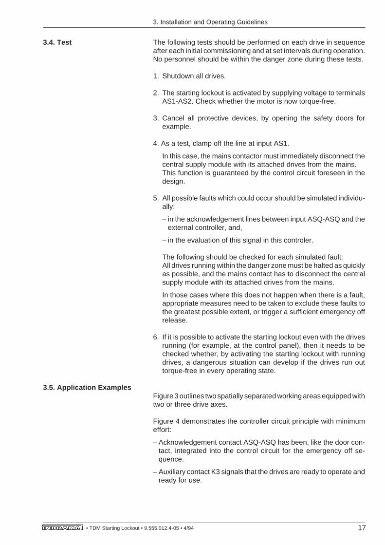
Production systems, transfer lines and machine tools often consist ofspatially separated working areas, e.g., processing units, transport,handling and storage systems (see Figure 3).
It is frequently necessary for personnel to either work or accesssomething in one working area while machinery is running in anadjacent working area. This means that the drive axes within anindividual’s working area must be secured against any uninten-tional motions so that an individual is not at risk from dangerousdrive motions caused by a fault somewhere else in the facility.
If the drive axes in adjacent working areas and in the danger zone arecentrally connected to the power mains by a supply unit (e.g., supplymodules TVM, KDV, TVD, KVR), then each direct-drive motor mustbe individually secured against unintentional motions. The dangerzone is the area in which the individual is working.
The starting lockout built into every INDRAMAT drive module makesit easy to safely power down the motor of each axis with a simpleswitch. This switch disconnects the output stage from the controlelectronics with the use of a relay in the hardware. The user gains thefollowing advantages:
1. Savings in cost and spaceA single power supply unit can feed the drive axes of severalworking areas. Individual power supply units are not needed foreach drive axes in every spatially separated working area.
In several applications, a large three-phase motor contactor withone or two axes is built into the motor supply lines. The motorcontactors make it possible to safely switch off these axis motors,and to use only one supply unit to operate all drives.
This function is now easy to perform without a power contactor onthe drive module by controlling the starting lockout input. Thisrepresents a savings in cost and space in the control cabinet.
1. Possible applications of the starting lockout
6 TDM Starting Lockout • 9.555.012.4-05 •4/94 •
2. Increased safety and reliability:
Personnel safety and facility reliability are increased because amains contactor is not needed to disconnect the motor from thedrive module.
– Eliminated are breakdowns caused by frequent switching, gum-ming or burning of the contacts of this contactor due to high loadcurrents.
The danger of damage to the motor mains contacts from improperhandling or commissioning is eliminated.
– The motors no longer brake uncontrolled with a power failure.
A motor contactor without a mechanical locking mechanism isdropped in a power failure. This means the motor will idle and theDC bus energy cannot be used for braking.
– The existing mains contactor is presently used to secure againstunintentional motions. It is switched on and off once during everyduty cycle. With a starting lockout in an INDRAMAT drive modulethe mains contactor does not need to be frequently switched, i.e.,with every cycle. It is only used with E-stops, for maintenance andinspection work throughout the plant, and with every total shut-down. There is less wear and tear, and failures occur lessfrequently.
– If two faults occur simultaneously, then a motor can run upuncontrolled if a motor contactor is used to secure against uninten-tional motions .
Example:
– speed command voltage at maximum due to fault in NC, and,
– the motor contactor fails.
In the unlikely event that two faults occur simultaneously in thepower supply, then the motor will only jerk if an internal startinglockout is in the INDRAMAT drive amplifier.
The internal control circuits and the output stage control areinternally locked for additional safety. An external motor contactordoes not ensure an additional internal locking of the drive electron-ics.
1. Applications
7• TDM Starting Lockout • 9.555.012.4-05 • 4/94
1. Applications
– The drive is secured by applying power to the starting lockoutinput. This meets the following safety requirements:
I. Quickest possible standstillThe drives must be brought to a standstill „as quickly as possible“in an emergency, in other words, in a dangerous situation (VDEGuidelines 0113/EN 60204, Part 1, Para. 5.6.1).
If an external voltage failure should occur in the control circuit of theAS starting lockout while the motor is rotating, then the drive is notswitched off and cannot continue to run. If a drive is running orsomething is being processed at the time this happens, no tool orworkpiece will be damaged once the drive is cleared.There can be a controlled electrical shutdown of the drives via theNC and the drive module.
II. No automatic restartsThe drives cannot automatically restart when power is reappliedto the starting lockout input (VDE 0113/EN 60204, Part 1, Para.5.4, VDI 2853, Sec. 3.1.2.3). The drives are blocked.
III. Remaining in a safe state with a faultA drive will remain in a safe state even with a fault, e.g., the controlvoltage drops off at the lockout input. This is in accordance with theGuidelines VDE 0113/EN 60204, Part 1, Para. 5.7.2 („Specialcurrent circuits that serve safety purposes must take on theirsecure state in the event of a failure.“), and VDE 2853, Para.3.1.2.1.1.
This condition is met because
– the controller enable signal and the command input keep the driveblocked, and,
– once the fault has occurred, the mains contactor immediatelydisconnects the power supply unit from the mains via the mainscontactor by the acknowledgement contact on the drive controller.This completely switches all drives dead.
8 TDM Starting Lockout • 9.555.012.4-05 •4/94 •
1.2. Operating individual axesduring installation
Drives are frequently run individually during installation. In this caseas well, personnel is often found within the danger zone. Generally,the acknowledgement switch is used to switch on the mains contactorto operate the axes. The mains contactor is then switched off againif unwanted movement occurs, or at the end of an operation.
The safety of personnel within a danger zone is increased, if thestarting lockout is additionally built into INDRAMAT’s drive modules.It helps to secure against unwanted starts during installation . Thisis possible because the internal, forcibly-connected contacts meanthat the axes not being run can be additionally blocked.
In addition, using this relay to switch the motors on and off reduceswear and tear. In effect, it also increases reliability and safety.
1. Applications
9• TDM Starting Lockout • 9.555.012.4-05 • 4/94
2.1. Motor controller function
2. How the StartingLockout Works
2. How the Starting Lockout Works
The power for motor current and thus the torque are advanced via thefinal output stage (driver) of the drive module. The extent of thecurrent in the three phases of the three-phase motor is transmitted bythe controller electronics to the final output stage in the form of aswitch-mode pulse-width modulated signal.
In this case, the controller electronics serve the following purpose:
The greater the width of the pulse or the switch-mode ratio, thegreater the motor current. The three currents in the three phases ofthe motor must additionally be adjusted, in terms of amount andphase position, to the rotor position given at that point in time, forsufficient torque to be produced.
There can be no motor revolutions at the motor shaft if there is nopulse-width modulated signal at the final output stage.
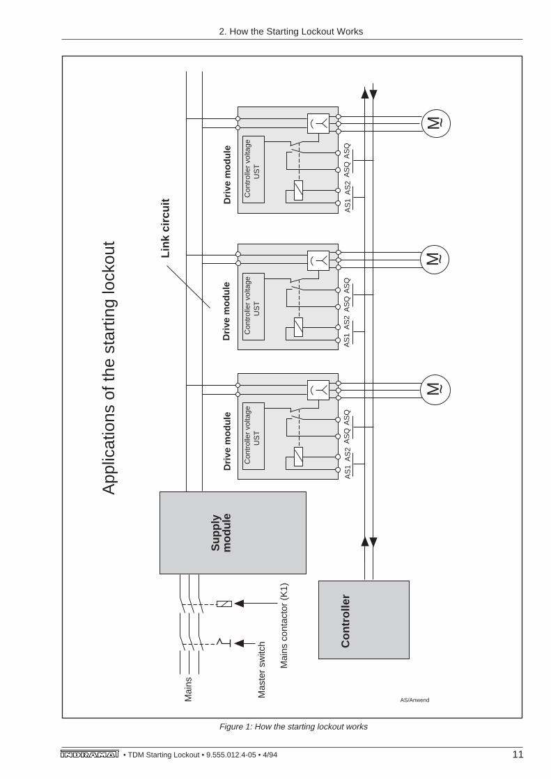
The signal at terminals AS1-AS2 of INDRAMAT’s drive moduleactivates an internal relay which has two forcibly-connected contacts(see Fig. 1). The relay has been quality controlled.
– The first contact of this relay separates the internal controller voltageof the final output stage in the hardware.
– The control and controller electronics are simultaneously and addi-tionally blocked. This achieves double redundancy.
– The second contact (acknowledgement contact) signals the activa-tion of the first contact to the outside.
A disconnection of the output stage controller is signalled via thisadditional acknowledgement contact (contact) ASQ-ASQ, to verifywhether the relay has actually been activated or not. This contact isforcibly-connected to the primary contact.
A relay failure or a wire break in the conductors to the starting lockoutinputs AS1-AS2 is immediately recognized by this zero-potentialacknowledgement contact in the external control. The central mainscontactor is then immediately disconnected.
This means it is not possible, in the event of a fault and given allconceivable possibilities, that a switch-mode motor current (alternat-ing current) could be produced within the electrical facilities of themachine which could make the motor move.
It is also not possible for a current to flow through the motor even whena fault occurs in one of the six final output stages. The drive does notmove. This fault is immediately acknowledged
– as soon as personnel has moved out of the danger zone,
– when the machine or sector of the facility has been properlyreblocked.
2.2. Using the starting lock-out signal to secure poweroff
10 TDM Starting Lockout • 9.555.012.4-05 •4/94 •
and the drive is reactivated
– by disconnecting starting lockout inputs AS1-AS2,
– by electronically enabling the controller amplifier, and,
– by entering the speed set-point.
This fault causes an excessively high current which triggers aresponse from the fuses in the drive module. Then the mainscontactor disconnects all drives from the mains. Message „BS“ on thedefective drive module also displays the fault overccurrent.
2. How the Starting Lockout Works
11• TDM Starting Lockout • 9.555.012.4-05 • 4/94
M
Sup
ply
mod
ule
Con
trol
ler
Con
trol
ler
volta
ge
US
T
Driv
e m
odul
eD
rive
mod
ule
Link
circ
uit
AS
1A
S2
AS
QA
SQ
AS
1A
S2
AS
QA
SQ
~M ~
~
Mai
ns
Mas
ter
switc
h
Mai
ns c
onta
ctor
(K
1)
AS/Anwend
App
licat
ions
of t
he s
tart
ing
lock
out
Con
trol
ler
volta
ge
US
T
M
Con
trol
ler
volta
ge
US
T
Driv
e m
odul
e
AS
1A
S2
AS
QA
SQ
Figure 1: How the starting lockout works
2. How the Starting Lockout Works
12 TDM Starting Lockout • 9.555.012.4-05 •4/94 •
It is not permitted in these cases to just disconnect the mainscontactor or activate the starting lockout.
3. Installation andOperating Guidelines
3.1. Guidelines fordisconnecting the mains,for shutdowns and securingagainst unwanted starts
The NC and the drive module cannot be used to operate thedrives once the starting lockout has been activated. Themotor is torque-free. A controlled operation of the axes is nolonger possible.
During the planning stage and at that time when the machineis commissioned it should be determined that the startinglockout can only be activated when the motor is standingstill. This applies to those cases where a torque-free operationof the drive can cause damage. It is therefore necessary withhanging axes to tightly clamp the axis before activating themechanical brake.
3. Installation and Operating Guidelines
The master switch must be used to disconnect all of the machine’selectrical equipment from the mains in the following instances:
– when cleaning the machine
– for maintenance and repairs
– prior to long breaks in operation
3.1.1. Using the master switchto disconnect the mains
The master switch must adhere to the guidelines outlined in EN60204/VDE 0113, Sec. 5.6.2. It is of extreme importance that it canbe locked into an off position.
In an emergency off/emergency stop situation the mains contactormust be disconnected directly so that all main current circuits areswitched to zero potential. Those main current circuits that servesafety purposes must be disconnected first, but not until thesemeasures have been concluded.An emergency off situation is defined as danger to either personnelor machinery in the presence of several faults or problems.
The starting lockout exclusively serves to secure the attached motorsagainst unintentional starts caused by a fault. Activating it while themotor is running does not automatically guarantee that the drives willbe safely shutdown.
3.1.2. Using the mainscontactor to disconnect themains
3.1.3. Using the startinglockout to secure againstunwanted starts
13• TDM Starting Lockout • 9.555.012.4-05 • 4/94
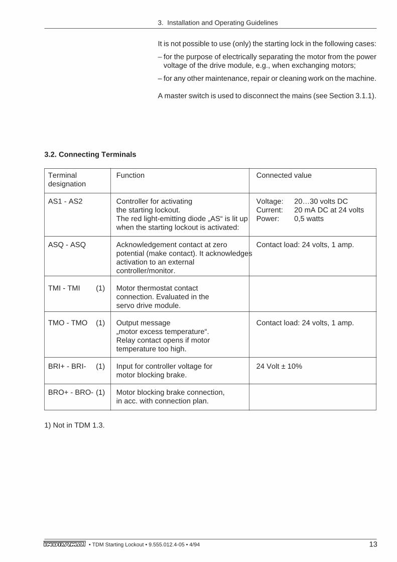
3.2. Connecting Terminals
Terminal Function Connected valuedesignation
AS1 - AS2 Controller for activating Voltage: 20…30 volts DCthe starting lockout. Current: 20 mA DC at 24 voltsThe red light-emitting diode „AS“ is lit up Power: 0,5 wattswhen the starting lockout is activated:
ASQ - ASQ Acknowledgement contact at zero Contact load: 24 volts, 1 amp.potential (make contact). It acknowledgesactivation to an externalcontroller/monitor.
TMI - TMI (1) Motor thermostat contactconnection. Evaluated in theservo drive module.
TMO - TMO (1) Output message Contact load: 24 volts, 1 amp.„motor excess temperature“.Relay contact opens if motortemperature too high.
BRI+ - BRI- (1) Input for controller voltage for 24 Volt ± 10%motor blocking brake.
BRO+ - BRO- (1) Motor blocking brake connection,in acc. with connection plan.
1) Not in TDM 1.3.
3. Installation and Operating Guidelines
It is not possible to use (only) the starting lock in the following cases:
– for the purpose of electrically separating the motor from the powervoltage of the drive module, e.g., when exchanging motors;
– for any other maintenance, repair or cleaning work on the machine.
A master switch is used to disconnect the mains (see Section 3.1.1).
14 TDM Starting Lockout • 9.555.012.4-05 •4/94 •
3. Installation and Operating Guidelines
The function and reliability of the starting lockout in its interaction withall other system components of the machine or facility are only asgood and as safe as the extent to which the following guidelines weretaken into consideration during planning and were checked duringthe commissioning of the machine.
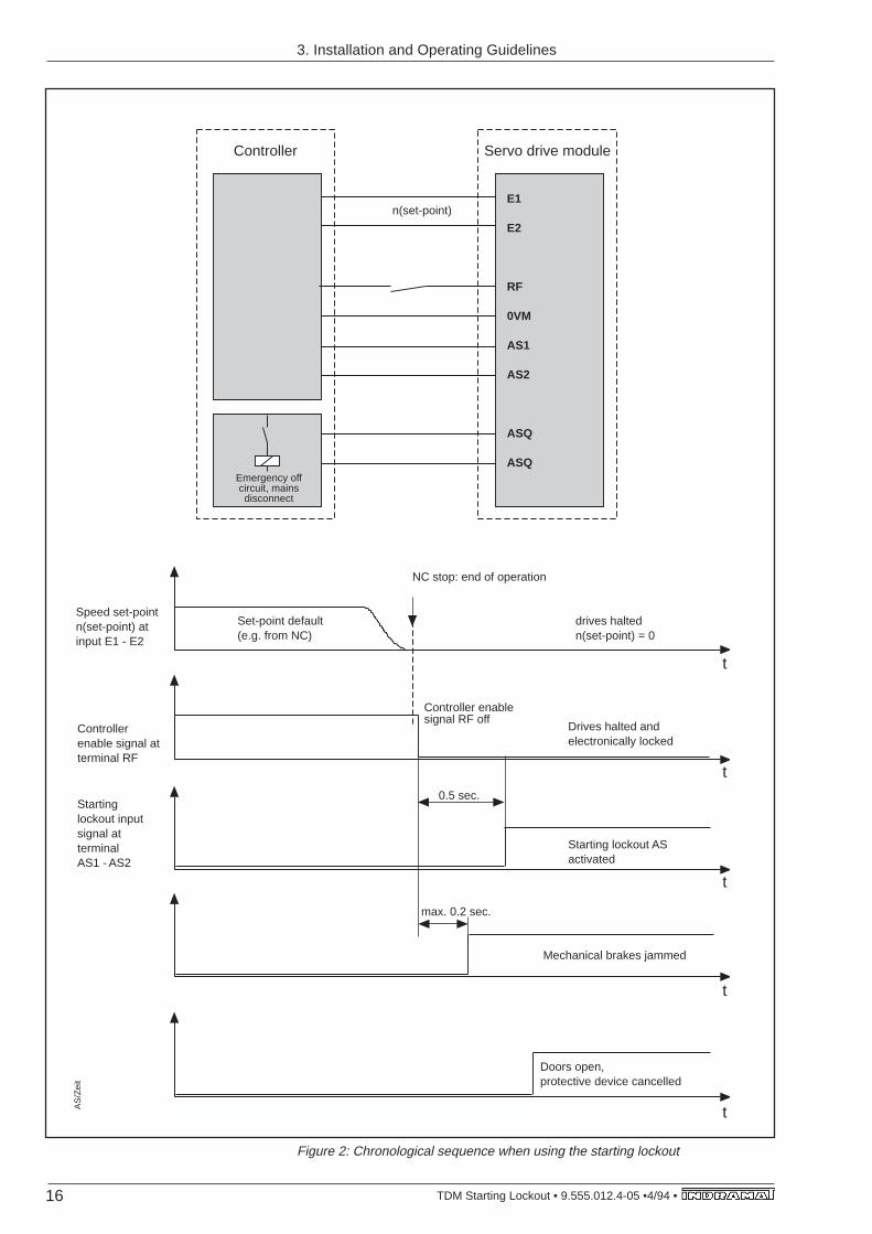
Figure 2 outlines the chronological sequence:
1. Shutdown drives:
The drives which are to be shutdown must first be brought to restbefore the starting lockout can be activated.
The starting lockout can only be used where a torque-free slowingdown can cause damage, and can only be activated when the motoris standing still. It is otherwise not possible to electrically shutdown arunning drive with the use of a drive module.
A starting lockout should only be activated, even when the motor isrunning, if a safe slowing down without a brake via the drive moduleis guaranteed.
2. Drive electronically blocked:
The speed set-point input (terminals E1-E2, E3-OVM, E4-OVM)must be set to zero, and the controller enable input signal (terminalRF) of the drive amplifier must be connected to OVM. This increasesboth safety and redundancy.
3. Activating the starting lockout:
A voltage of 20 ... 30 volts must be placed between the input terminalsAS1-AS2 to activate the starting lockout (0.5 watts at 24 volts ofapplied voltage).The switching of the starting lockout relay in the drive amplifier ishereby confirmed to the external controller by closing the potential-free acknowledgement contact (output ASQ-ASQ).
The red diode „AS“ on the front plate lights up simultaneously.
4. Commissioning operation:
If one or several axes are to be operated during the commissioningoperation with protective devices cancelled, then this should only bepossible if qualified personnel enable this type of operation with a keyswitch.
All drives must otherwise be disconnected from the mains via theemergency off circuit, in this case automatically. The respectivecommissioning guidelines must be followed.
5. Cancelling the protective devices
The protective devices for the drive’s defined danger zone can nowbe cancelled. Guard doors can, for example, be opened, locks andcutoffs for the danger zone can be cancelled.
3.3. Sequence and cyclewhen using the starting lock-out
15• TDM Starting Lockout • 9.555.012.4-05 • 4/94
3. Installation and Operating Guidelines
Once the protective devices have been cancelled, then the automaticemergency stop must be immediately activated if one of the followingfaults occur. All the drives connected to the central supply module arehalted and hereby disconnected from the mains via the mainscontactor:
– Activation of the starting lockout is not acknowledged. The acknowl-edgement contact (output ASQ-ASQ) remains open. The emer-gency off circuit must open because it is necessary for the externalcontroller to definitely recognize this fault.Possible causes: The controller signal does not arrive at input AS1-AS2 of the drive amplifier, or the internal starting lockout relay isdefective.
– There is a fault in the acknowledgement line between output ASQ-ASQ and the external controller, which evaluates the acknowledge-ment via this acknowledgement contact. Or there is a fault in thecontroller itself.
6. Access ready:
Once all the preceding steps have been performed and checked, thenall the drives in the disconnected working area have been securedagainst unwanted movement.It is now possible for personnel to enter this zone and access theequipment.
16 TDM Starting Lockout • 9.555.012.4-05 •4/94 •
Mechanical brakes jammed
E1
E2
RF
0VM
AS1
AS2
ASQ
ASQ
Controller
Emergency off circuit, mains disconnect
Speed set-pointn(set-point) atinput E1 - E2
Controller enable signal at terminal RF
Starting lockout input signal at terminalAS1 - AS2
t
t0.5 sec.
NC stop: end of operation
drives haltedn(set-point) = 0
Controller enable signal RF off
Drives halted and electronically locked
t
Starting lockout AS activated
t
t
Doors open,protective device cancelled
AS
/Zei
t
Servo drive module
n(set-point)
Set-point default(e.g. from NC)
max. 0.2 sec.
3. Installation and Operating Guidelines
Figure 2: Chronological sequence when using the starting lockout
17• TDM Starting Lockout • 9.555.012.4-05 • 4/94
3.4. Test
3. Installation and Operating Guidelines
The following tests should be performed on each drive in sequenceafter each initial commissioning and at set intervals during operation.No personnel should be within the danger zone during these tests.
1. Shutdown all drives.
2. The starting lockout is activated by supplying voltage to terminalsAS1-AS2. Check whether the motor is now torque-free.
3. Cancel all protective devices, by opening the safety doors forexample.
4. As a test, clamp off the line at input AS1.
In this case, the mains contactor must immediately disconnect thecentral supply module with its attached drives from the mains.This function is guaranteed by the control circuit foreseen in thedesign.
5. All possible faults which could occur should be simulated individu-ally:
– in the acknowledgement lines between input ASQ-ASQ and theexternal controller, and,
– in the evaluation of this signal in this controler.
The following should be checked for each simulated fault:All drives running within the danger zone must be halted as quicklyas possible, and the mains contact has to disconnect the centralsupply module with its attached drives from the mains.
In those cases where this does not happen when there is a fault,appropriate measures need to be taken to exclude these faults tothe greatest possible extent, or trigger a sufficient emergency offrelease.
6. If it is possible to activate the starting lockout even with the drivesrunning (for example, at the control panel), then it needs to bechecked whether, by activating the starting lockout with runningdrives, a dangerous situation can develop if the drives run outtorque-free in every operating state.
Figure 3 outlines two spatially separated working areas equipped withtwo or three drive axes.
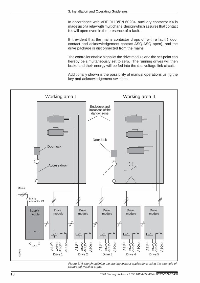
Figure 4 demonstrates the controller circuit principle with minimumeffort:
– Acknowledgement contact ASQ-ASQ has been, like the door con-tact, integrated into the control circuit for the emergency off se-quence.
– Auxiliary contact K3 signals that the drives are ready to operate andready for use.
3.5. Application Examples
18 TDM Starting Lockout • 9.555.012.4-05 •4/94 •
Access door
Mains
Working area I Working area II
Enclosure and limitations of the
danger zone
Door lock
Door lock
Supplymodule
Drivemodule
Mains contactor K1
Bb 1
AS
1
AS
2
AS
Q
AS
Q
Drive 1 Drive 2 Drive 3 Drive 4 Drive 5
AS
/Prin
z
Drivemodule
AS
1
AS
2
AS
Q
AS
Q
AS
1
AS
2
AS
Q
AS
Q
Drivemodule
AS
1
AS
2
AS
Q
AS
Q
Drivemodule
AS
1
AS
2
AS
Q
AS
Q
AS
Q
Drivemodule
AS
1
AS
2
AS
Q
AS
Q
Figure 3: A sketch outlining the starting lockout applications using the example ofseparated working areas.
3. Installation and Operating Guidelines
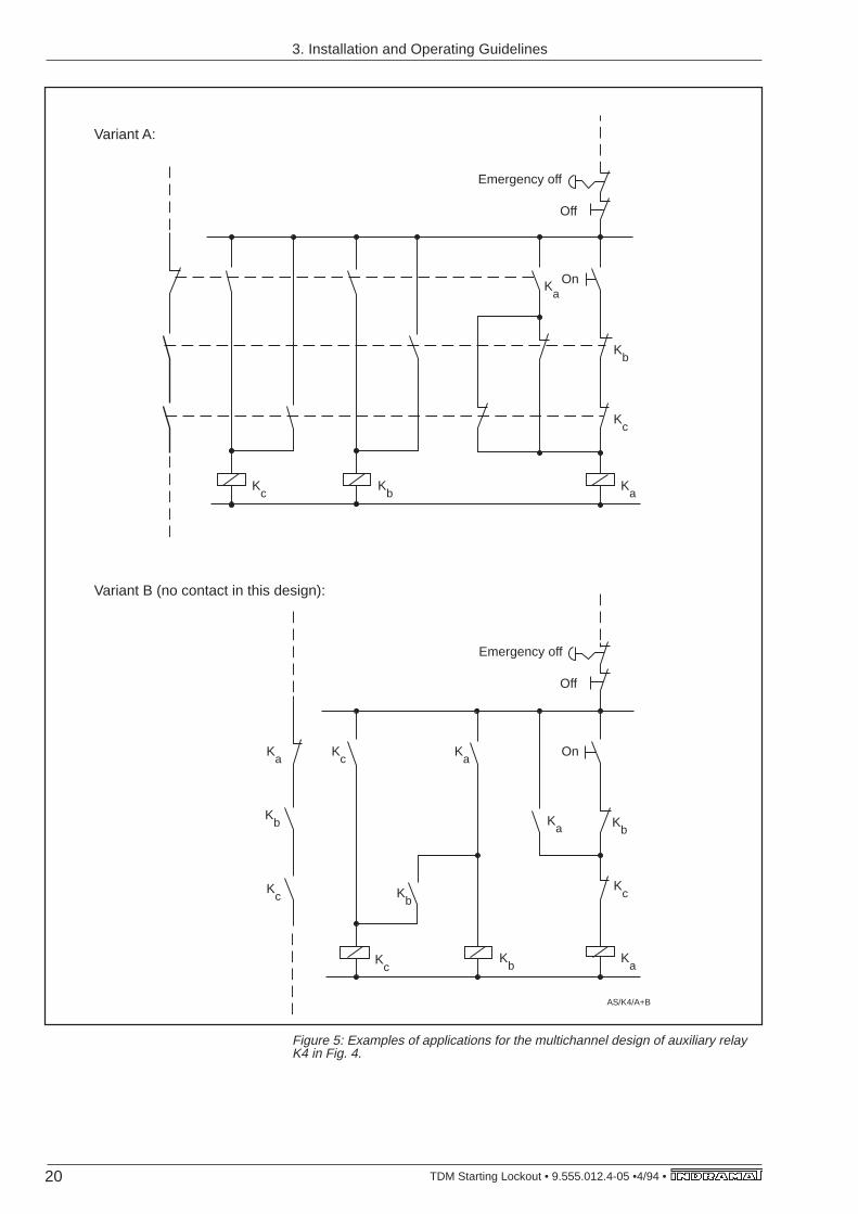
In accordance with VDE 0113/EN 60204, auxiliary contactor K4 ismade up of a relay with multichanel design which assures that contactK4 will open even in the presence of a fault.
It it evident that the mains contactor drops off with a fault (=doorcontact and acknowledgement contact ASQ-ASQ open), and thedrive package is disconnected from the mains.
The controller enable signal of the drive module and the set-point canhereby be simultaneously set to zero. The running drives will thenbrake and their energy will be fed into the d.c. voltage link circuit.
Additionally shown is the possibility of manual operations using thekey and acknowledgement switches.
19• TDM Starting Lockout • 9.555.012.4-05 • 4/94
Figure 4: Examples of starting lockout applications: Controller circuitry of Fig. 3.
24V
-
Sta
rtin
g lo
ckou
tof
the
driv
esW
orki
ng a
rea
II
Sta
rtin
g lo
ckou
tof
the
driv
esW
orki
ng a
rea
II
Sup
ply
unit
for
faul
t re
cogn
ition
re
ady
to
oper
ate
Bb1
Driv
es lo
cked
in w
orki
ng a
rea
II
Driv
es lo
cked
in w
orki
ng a
rea
I
24V
-
Doo
r co
ntac
t for
w
orki
ng a
rea
I
Doo
r co
ntac
t for
wor
king
are
a II
Em
erge
ncy-
Sto
p
Off
On
Mul
ticha
nnel
au
xilia
ry
rela
ys w
ith
cont
act
mon
itorin
g
Mai
ns
cont
acto
r K
1230V
~
AS/manuell
AS
Q
AS
Q
K4A
SQ
AS
Q
AS
QA
S2
AS
2A
S2
AS
2A
S2
AS
1A
S1
AS
1A
S1
AS
1K
3
K3
3. Installation and Operating Guidelines
20 TDM Starting Lockout • 9.555.012.4-05 •4/94 •
Kb
Kc
Ka
Kc
Kb
Ka
On
Emergency off
Off
Ka
On
Emergency off
Off
KbK
c
AS/K4/A+B
Kc
Kb
Ka
Ka
Kb
Kc
Kc
Kb
Ka
Variant A:
Variant B (no contact in this design):
Figure 5: Examples of applications for the multichannel design of auxiliary relayK4 in Fig. 4.
3. Installation and Operating Guidelines
21• TDM Starting Lockout • 9.555.012.4-05 • 4/94
4. Controller typesand related plans
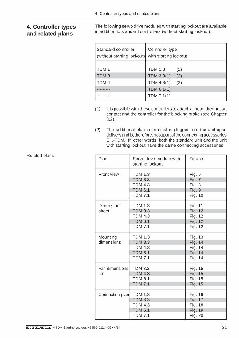
The following servo drive modules with starting lockout are availablein addition to standard controllers (without starting lockout).
Standard controller Controller type
(without starting lockout) with starting lockout
TDM 1 TDM 1.3 (2)
TDM 3 TDM 3.3(1) (2)
TDM 4 TDM 4.3(1) (2)
--------- TDM 6.1(1)
--------- TDM 7.1(1)
(1) It is possible with these controllers to attach a motor thermostatcontact and the controller for the blocking brake (see Chapter3.2).
(2) The additional plug-in terminal is plugged into the unit upondelivery and is, therefore, not a part of the connecting accessoriesE...-TDM. In other words, both the standard unit and the unitwith starting lockout have the same connecting accessories.
Related plansPlan Servo drive module with Figures
starting lockout
Front view TDM 1.3 Fig. 6TDM 3.3 Fig. 7TDM 4.3 Fig. 8TDM 6.1 Fig. 9TDM 7.1 Fig. 10
Dimension TDM 1.3 Fig. 11sheet TDM 3.3 Fig. 12
TDM 4.3 Fig. 12TDM 6.1 Fig. 12TDM 7.1 Fig. 12
Mounting TDM 1.3 Fig. 13dimensions TDM 3.3 Fig. 14
TDM 4.3 Fig. 14TDM 6.1 Fig. 14TDM 7.1 Fig. 14
Fan dimensions TDM 3.3 Fig. 15for TDM 4.3 Fig. 15
TDM 6.1 Fig. 15TDM 7.1 Fig. 15
Connection plan TDM 1.3 Fig. 16TDM 3.3 Fig. 17TDM 4.3 Fig. 18TDM 6.1 Fig. 19TDM 7.1 Fig. 20
4. Controller types and related plans
22 TDM Starting Lockout • 9.555.012.4-05 •4/94 •
+15
V
0VM
-15V
Tach
o
BLC
1
BLC
2
BLC
3
0VM
X5
X6
ZERO ADJ
RESET
S1
X8
L+
L-
A3
A2
A1
POSITION FOR OPERATING PARAMETERPROGRAMMING MODULE, PLUG INCORRECT MODULE, BEFORE START UPPlatz für Betriebsdaten-Programmierungs-modul. Vor dem Einschalten korrektesModul einstecken.
TDM ...-100-300-W0236226 K39/91
CONTROLLERAC SERVO
SN240060-02029 A01
X1
X2
Servo drive module
Electrical connecting accessoriesand programming module
AC
PO
WE
R O
UT
PU
T
DA
NG
ER
HIG
H V
OLT
AG
EM
otor
ansc
hluß
WARNING300 VDC INPUT
DISCHARGE TIMEEntladezeit > 1 Min.
POWER SUPPLY OUTPUTVOLTAGE RATING, MUST
NOT EXCEED POWERINPUT VOLTAGE DATA
Nur mit Versorgungseinheitgleicher od. kleinerer POWER-Spannungsangabe betreiben
+24V±15VBLC1BLC2BLC3
TachoPOWER
RFBbTSBS
Offset
adjust
E3
E1
E4
E2
Bb
Bb
RF
+15
V
-15V Ired MA
Tsen
se
0VM
0VM
1 2 3 4 5 6 7 8 9 10 11 12 13 14 15
1 2 3 4 5 6 7 8 9 10
FrontanTDM13
Busbars
Bus terminal X1
Programming module MOD with rating plate
Plug-in terminals 1 2 3 4
AS
1
AS
2
AS
Q
AS
Q
X9
1 2 3 4
Contr.: TDM 1.3-100-300-W1Motor: MAC 112D-.-FD-.-CCurrent (A): peak/cont.: 100/75Operating rpm: 2000 MA: 0,05 V/A
MOD 1/1X077-002Input rpm/VE1/E2 2000/10E3 2000/10E4 2000/10
OPERATING PARAMETER: PROGRAMMING MODULE
ATTENTION: MOTOR AND CONTROLLER-TYPE INDICATED ON THE MODULE MUST AGREE
WITH THE DEVISES IN USE. OTHERWISE LACK OF PERFORMANCE
AND DANGER OF DAMAGE MAY OCCUR
Betriebsdaten-Programmierungsmodul
Achtung : Motor- und Verstärkertypenangaben müssen mit der
Installation übereinstimmen, sonst Schädigungsgefahr.
AS
1 2 3 4 5 6 7 8 9 10
1 2 3 4 5 6 7 8 9 10 11 12 13 14 15
ATTENTION!NEVER REMOVE OR INSTALL THISPLUG WHILE VOLTAGE IS APPLIED.BLACK CABLE ON THE BOTTOM!Verbindung nie unter Spannunglösen bzw. stecken.Schwarze Leitung immer unten!
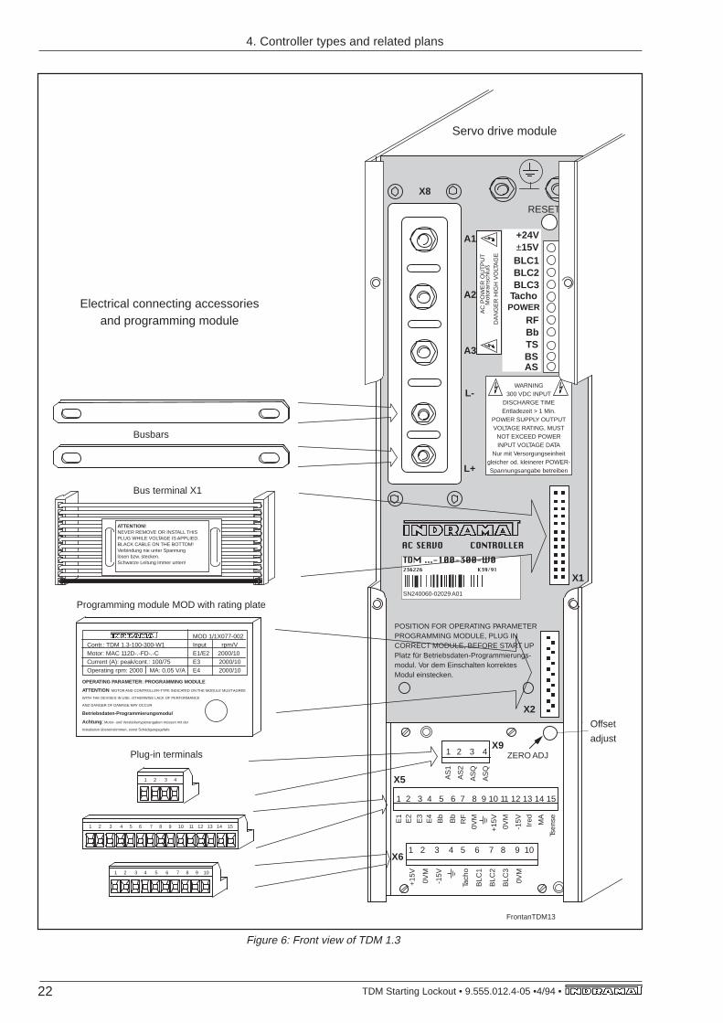
Figure 6: Front view of TDM 1.3
4. Controller types and related plans
23• TDM Starting Lockout • 9.555.012.4-05 • 4/94
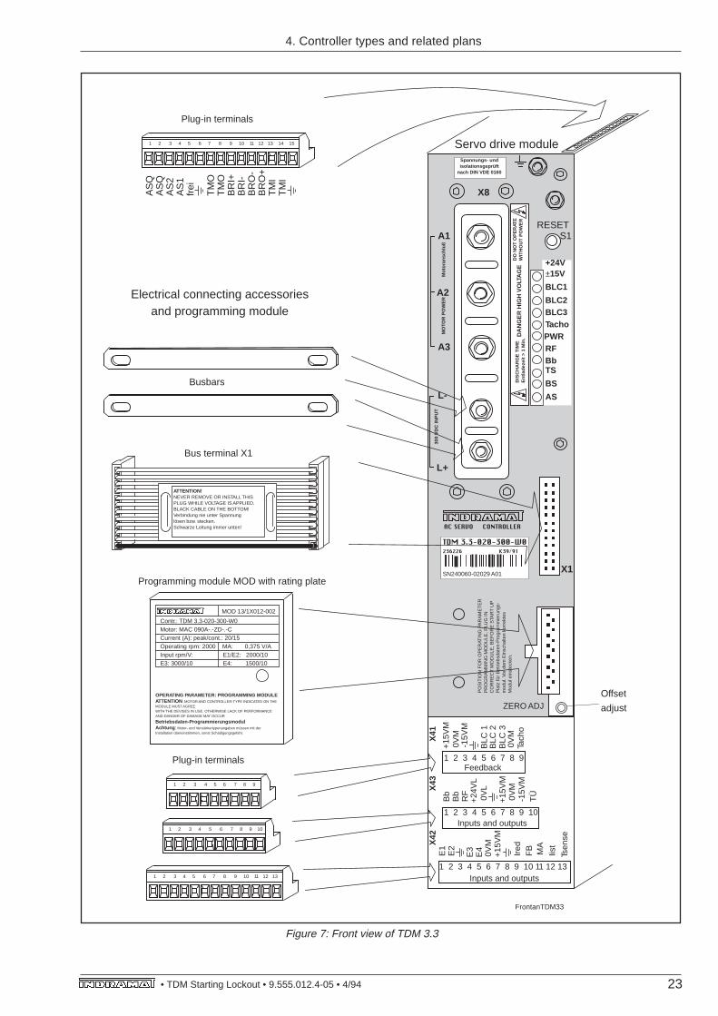
Figure 7: Front view of TDM 3.3
ZERO ADJ
RESETS1
X8
L+
L-
A3
A2
A1
PO
SIT
ION
FO
R O
PE
RAT
ING
PA
RA
ME
TE
RP
RO
GR
AM
MIN
G M
OD
ULE
, PLU
G IN
CO
RR
EC
T M
OD
ULE
, BE
FO
RE
STA
RT
UP
Pla
tz fü
r B
etrie
bsda
ten-
Pro
gram
mie
rung
s-m
odul
. Vor
dem
Ein
scha
lten
korr
ekte
sM
odul
ein
stec
ken.
CONTROLLERAC SERVO
X1
Servo drive module
Electrical connecting accessoriesand programming module
TDM 3.3-020-300-W0236226 K39/91
SN240060-02029 A01
DA
NG
ER
HIG
H V
OLT
AG
ED
O N
OT
OP
ER
ATE
WIT
HO
UT
PO
WE
R
Spannungs- undisolationsgeprüft
nach DIN VDE 0160
+24V±15V
BLC1
BLC2BLC3TachoPWRRFBbTS
BS
Offset
adjust
FrontanTDM33
Inputs and outputs
Feedback
Inputs and outputs
1 2 3 4 5 6 7 8 9
1 2 3 4 5 6 7 8 9 10
1 2 3 4 5 6 7 8 9 10 11 12 13
E1
E2
E3
E4
+15
VM
+15
VM
Ired
0VM
FB MA
Iist
TÜ
Tsen
se
1 2 3 4 5 6 7 8 9 10
Bb
-15V
M0V
M
RF
Bb
+24
VL
0VL
1 2 3 4 5 6 7 8 9
+15
VM
-15V
M0V
M
0VM
BLC
2B
LC 1
BLC
3
Tach
o
X41
X42
X43
Contr.: TDM 3.3-020-300-W0Motor: MAC 090A-.-ZD-.-CCurrent (A): peak/cont.: 20/15Operating rpm: 2000 MA: 0,375 V/AInput rpm/V: E1/E2: 2000/10E3: 3000/10 E4: 1500/10
MOD 13/1X012-002
OPERATING PARAMETER: PROGRAMMING MODULEATTENTION: MOTOR AND CONTROLLER-TYPE INDICATED ON THEMODULE MUST AGREEWITH THE DEVISES IN USE. OTHERWISE LACK OF PERFORMANCEAND DANGER OF DAMAGE MAY OCCUR
Betriebsdaten-ProgrammierungsmodulAchtung : Motor- und Verstärkertypenangaben müssen mit derInstallation übereinstimmen, sonst Schädigungsgefahr.
MO
TOR
PO
WE
R
Mot
oran
schl
uß
300
VD
C IN
PU
T
DIS
CH
AR
GE
TIM
EE
ntla
deze
it >
1 M
in.
AS
Busbars
Bus terminal X1
Programming module MOD with rating plate
Plug-in terminals
1 2 3 4 5 6 7 8 9 10 11 12 13
1 2 3 4 5 6 7 8 9 10 11 12 13 14 15A
SQ
AS
QA
S2
AS
1fr
ei
TM
OT
MO
BR
I+B
RI-
BR
O-
BR
O+
TM
IT
MI
Plug-in terminals
ATTENTION!NEVER REMOVE OR INSTALL THISPLUG WHILE VOLTAGE IS APPLIED.BLACK CABLE ON THE BOTTOM!Verbindung nie unter Spannunglösen bzw. stecken.Schwarze Leitung immer unten!
4. Controller types and related plans
24 TDM Starting Lockout • 9.555.012.4-05 •4/94 •
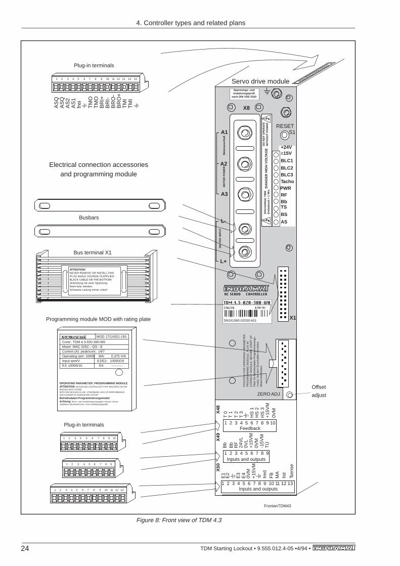
Figure 8: Front view of TDM 4.3
ZERO ADJ
RESETS1
X8
L+
L-
A3
A2
A1
PO
SIT
ION
FO
R O
PE
RAT
ING
PA
RA
ME
TE
RP
RO
GR
AM
MIN
G M
OD
ULE
, PLU
G IN
CO
RR
EC
T M
OD
ULE
, BE
FO
RE
STA
RT
UP
Pla
tz fü
r B
etrie
bsda
ten-
Pro
gram
mie
rung
s-m
odul
. Vor
dem
Ein
scha
lten
korr
ekte
sM
odul
ein
stec
ken.
CONTROLLERAC SERVO
X1
Servo drive module
Electrical connection accessoriesand programming module
TDM 4.3-020-300-W0236226 K39/91
SN241060-02030 A01
DA
NG
ER
HIG
H V
OLT
AG
ED
O N
OT
OP
ER
ATE
WIT
HO
UT
PO
WE
R
Spannungs- undisolationsgeprüft
nach DIN VDE 0160
+24V±15V
BLC1
BLC2BLC3TachoPWRRFBbTS
BS
Offset
adjust
FrontanTDM43
Inputs and outputs
Feedback
Inputs and outputs1 2 3 4 5 6 7 8 9 10 11 12 13
E1
E2
E3
E4
+15
VM
+15
VM
Ired
0VM
FB
MA
Iist
TÜ
Tsen
se
1 2 3 4 5 6 7 8 9
Bb
-15V
M0V
M
RF
Bb
24V
L0V
L
1 2 3 4 5 6 7 8 9 10
T 0
T 2
T 1
0VM
HS
2H
S 1
HS
3X48
X50
X49
MO
TOR
PO
WE
R
Mot
oran
schl
uß
300
VD
C IN
PU
T
DIS
CH
AR
GE
TIM
EE
ntla
deze
it >
1 M
in.
ASBusbars
Bus terminal X1
Programming module MOD with rating plate
Plug-in terminals
T 3
+15
VM
1 2 3 4 5 6 7 8 9 10 11 12 13 14 15
AS
QA
SQ
AS
2A
S1
frei
TM
OT
MO
BR
I+B
RI-
BR
O-
BR
O+
TM
IT
MI
Plug-in terminals
1 2 3 4 5 6 7 8 9
1 2 3 4 5 6 7 8 9 10
1 2 3 4 5 6 7 8 9 10 11 12 13
Contr.: TDM 4.3-020-300-W0Motor: MAC 025C-.-QS-.-ECurrent (A): peak/cont.: 14/7Operating rpm: 10000 MA: 0,375 V/AInput rpm/V: E1/E2: 10000/10E3: 10000/10 E4: ----------
MOD 17/1X001-193
OPERATING PARAMETER: PROGRAMMING MODULEATTENTION: MOTOR AND CONTROLLER-TYPE INDICATED ON THEMODULE MUST AGREEWITH THE DEVISES IN USE. OTHERWISE LACK OF PERFORMANCEAND DANGER OF DAMAGE MAY OCCUR
Betriebsdaten-ProgrammierungsmodulAchtung : Motor- und Verstärkertypenangaben müssen mit derInstallation übereinstimmen, sonst Schädigungsgefahr.
ATTENTION!NEVER REMOVE OR INSTALL THISPLUG WHILE VOLTAGE IS APPLIED.BLACK CABLE ON THE BOTTOM!Verbindung nie unter Spannunglösen bzw. stecken.Schwarze Leitung immer unten!
4. Controller types and related plans
25• TDM Starting Lockout • 9.555.012.4-05 • 4/94
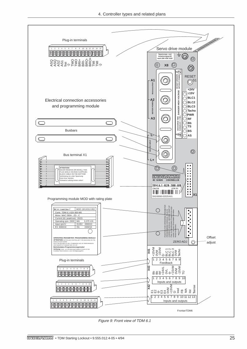
Figure 9: Front view of TDM 6.1
ZERO ADJ
RESETS1
X8
L+
L-
A3
A2
A1
PO
SIT
ION
FO
R O
PE
RAT
ING
PA
RA
ME
TE
RP
RO
GR
AM
MIN
G M
OD
ULE
, PLU
G IN
CO
RR
EC
T M
OD
ULE
, BE
FO
RE
STA
RT
UP
Pla
tz fü
r B
etrie
bsda
ten-
Pro
gram
mie
rung
s-m
odul
. Vor
dem
Ein
scha
lten
korr
ekte
sM
odul
ein
stec
ken.
CONTROLLERAC SERVO
X1
Servo drive module
Electrical connection accessoriesand programming module
TDM 6.1-020-300-W0236226 K39/91
SN240060-02029 A01
DA
NG
ER
HIG
H V
OLT
AG
ED
O N
OT
OP
ER
ATE
WIT
HO
UT
PO
WE
R
Spannungs- undisolationsgeprüft
nach DIN VDE 0160
+24V±15V
BLC1
BLC2BLC3TachoPWRRFBbTS
BS
Offset
adjust
FrontanTDM6
Inputs and outputs
Feedback
Inputs and outputs
1 2 3 4 5 6 7 8 9
1 2 3 4 5 6 7 8 9 10
1 2 3 4 5 6 7 8 9 10 11 12 13
E1
E2
E3
E4
+15
VM
+15
VM
Ired
0VM
FB MA
Iist
TÜ
Tsen
se
1 2 3 4 5 6 7 8 9 10
Bb
-15V
M0V
M
RF
Bb
+24
VL
0VL
1 2 3 4 5 6 7 8 9
+15
VM
-15V
M0V
M
0VM
BLC
2B
LC 1
BLC
3
Tach
o
X41
X42
X43
Contr.: TDM 6.1-020-300-W0Motor: MAC 090A-.-ZD-.-CCurrent (A): peak/cont.: 20/15Operating rpm: 2000 MA: 0,375 V/AInput rpm/V: E1/E2: 2000/10E3: 3000/10 E4: 1500/10
MOD 19/1X012-002
OPERATING PARAMETER: PROGRAMMING MODULEATTENTION: MOTOR AND CONTROLLER-TYPE INDICATED ON THEMODULE MUST AGREEWITH THE DEVISES IN USE. OTHERWISE LACK OF PERFORMANCEAND DANGER OF DAMAGE MAY OCCUR
Betriebsdaten-ProgrammierungsmodulAchtung : Motor- und Verstärkertypenangaben müssen mit derInstallation übereinstimmen, sonst Schädigungsgefahr.
MO
TOR
PO
WE
R
Mot
oran
schl
uß
300
VD
C IN
PU
T
DIS
CH
AR
GE
TIM
EE
ntla
deze
it >
1 M
in.
AS
Busbars
Bus terminal X1
Programming module MOD with rating plate
Plug-in terminals
1 2 3 4 5 6 7 8 9 10 11 12 13
1 2 3 4 5 6 7 8 9 10 11 12 13 14 15
AS
QA
SQ
AS
2A
S1
frei
TM
OT
MO
BR
I+B
RI-
BR
O-
BR
O+
TM
IT
MI
Plug-in terminals
ATTENTION!NEVER REMOVE OR INSTALL THISPLUG WHILE VOLTAGE IS APPLIED.BLACK CABLE ON THE BOTTOM!Verbindung nie unter Spannunglösen bzw. stecken.Schwarze Leitung immer unten!
4. Controller types and related plans
26 TDM Starting Lockout • 9.555.012.4-05 •4/94 •
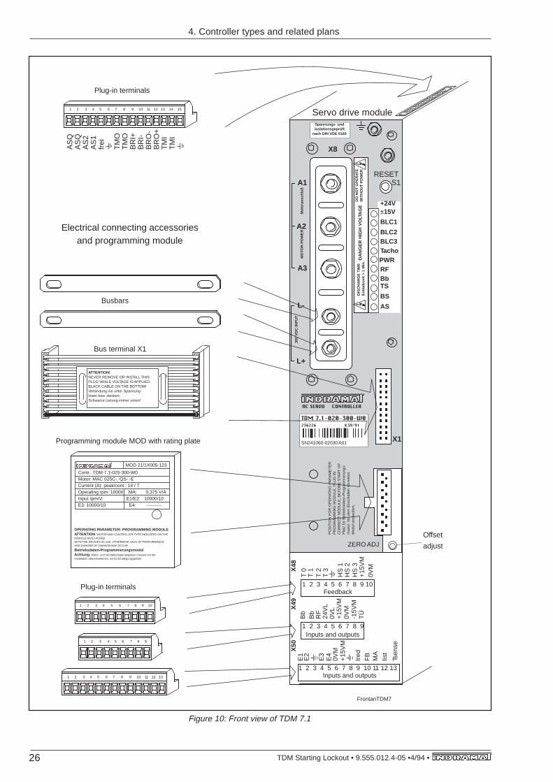
Figure 10: Front view of TDM 7.1
ZERO ADJ
RESETS1
X8
L+
L-
A3
A2
A1
PO
SIT
ION
FO
R O
PE
RAT
ING
PA
RA
ME
TE
RP
RO
GR
AM
MIN
G M
OD
ULE
, PLU
G IN
CO
RR
EC
T M
OD
ULE
, BE
FO
RE
STA
RT
UP
Pla
tz fü
r B
etrie
bsda
ten-
Pro
gram
mie
rung
s-m
odul
. Vor
dem
Ein
scha
lten
korr
ekte
sM
odul
ein
stec
ken.
CONTROLLERAC SERVO
X1
Servo drive module
Electrical connecting accessoriesand programming module
TDM 7.1-020-300-W0236226 K39/91
SN241060-02030 A01
DA
NG
ER
HIG
H V
OLT
AG
ED
O N
OT
OP
ER
ATE
WIT
HO
UT
PO
WE
R
Spannungs- undisolationsgeprüft
nach DIN VDE 0160
+24V±15V
BLC1
BLC2BLC3TachoPWRRFBbTS
BS
Offset
adjust
FrontanTDM7
Inputs and outputs
Feedback
Inputs and outputs1 2 3 4 5 6 7 8 9 10 11 12 13
E1
E2
E3
E4
+15
VM
+15
VM
Ired
0VM
FB
MA
Iist
TÜ
Tsen
se
1 2 3 4 5 6 7 8 9
Bb
-15V
M0V
M
RF
Bb
24V
L0V
L
1 2 3 4 5 6 7 8 9 10
T 0
T 2
T 1
0VM
HS
2H
S 1
HS
3X48
X50
X49
MO
TOR
PO
WE
R
Mot
oran
schl
uß
300
VD
C IN
PU
T
DIS
CH
AR
GE
TIM
EE
ntla
deze
it >
1 M
in.
ASBusbars
Bus terminal X1
Programming module MOD with rating plate
Plug-in terminals
T 3
+15
VM
1 2 3 4 5 6 7 8 9 10 11 12 13 14 15
AS
QA
SQ
AS
2A
S1
frei
TM
OT
MO
BR
I+B
RI-
BR
O-
BR
O+
TM
IT
MI
Plug-in terminals
1 2 3 4 5 6 7 8 9
1 2 3 4 5 6 7 8 9 10
1 2 3 4 5 6 7 8 9 10 11 12 13
Contr.: TDM 7.1-020-300-W0Motor: MAC 025C-.-QS-.-ECurrent (A): peak/cont.: 14 / 7Operating rpm: 10000 MA: 0,375 V/AInput rpm/V: E1/E2: 10000/10E3: 10000/10 E4: ----------
MOD 21/1X005-123
OPERATING PARAMETER: PROGRAMMING MODULEATTENTION: MOTOR AND CONTROLLER-TYPE INDICATED ON THEMODULE MUST AGREEWITH THE DEVISES IN USE. OTHERWISE LACK OF PERFORMANCEAND DANGER OF DAMAGE MAY OCCUR
Betriebsdaten-ProgrammierungsmodulAchtung : Motor- und Verstärkertypenangaben müssen mit derInstallation übereinstimmen, sonst Schädigungsgefahr.
ATTENTION!NEVER REMOVE OR INSTALL THISPLUG WHILE VOLTAGE IS APPLIED.BLACK CABLE ON THE BOTTOM!Verbindung nie unter Spannunglösen bzw. stecken.Schwarze Leitung immer unten!
4. Controller types and related plans
27• TDM Starting Lockout • 9.555.012.4-05 • 4/94
325
Out
let f
or c
oolin
g ai
rm
in. 8
0 m
m fo
rco
olin
g ai
r ou
tlet
355
min
. 80
mm
for
cool
ing
air
inle
t
Acc
ess
for
cool
ing
air
Tig
hten
ing
torq
ue M
(N
m)
for
term
inal
bol
t: M
6 =
5 N
mT
ight
enin
g to
rque
M
(Nm
) fo
r te
rmin
al b
olt:
M5
= 3
Nm
Tig
hten
ing
torq
ue M
(N
m)
for
term
inal
bol
t: M
5 =
1,5
Nm
A A
7
373
390
60
9
Maßblatt TDM13
20
Onl
y ap
plie
s to
des
ign
with
fan
12
X2
7
17
105
A
Saf
ety
guar
d
X9
X6
X5
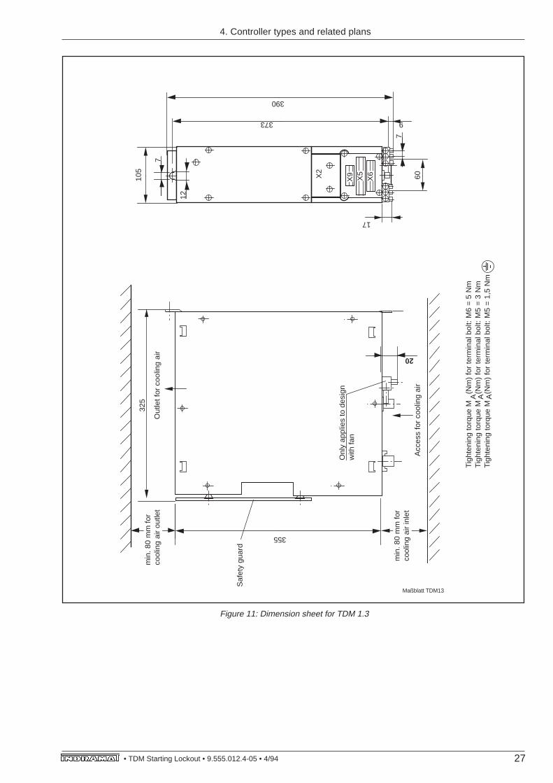
Figure 11: Dimension sheet for TDM 1.3
4. Controller types and related plans
28 TDM Starting Lockout • 9.555.012.4-05 •4/94 •
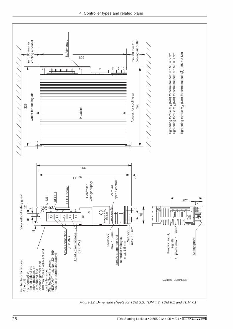
Figure 12: Dimension sheets for TDM 3.3, TDM 4.3, TDM 6.1 and TDM 7.1
325
Out
let f
or c
oolin
g ai
r
Hea
tsin
k
min
. 80
mm
for
cool
ing
air
outle
t
355Saf
ety
guar
d
min
. 80
mm
for
cool
ing
air
outle
t32
6
Acc
ess
for
cool
ing
air
Tigh
teni
ng to
rque
M
(Nm
) fo
r te
rmin
al b
olt X
8: M
6 =
5 N
mTi
ghte
ning
torq
ue M
(N
m)
for
term
inal
bol
t X8:
M5
= 3
Nm
Tigh
teni
ng to
rque
M
(Nm
) fo
r te
rmin
al b
olt
:
M5
= 3
Nm
A A
S1
A1
A2
A3 L- L+
X8
X1
Pro
gram
min
gm
odul
e
ZE
RO
-AD
J
712
373
390
70
7
9+1
Zer
o ad
j.sp
eed
cont
rol
Set
poi
ntm
ax. 1
.5 m
m
Rea
dy to
ope
rate
and
cont
rolle
r vo
ltage
sm
ax. 1
.5 m
m
Fee
dbac
km
ax. 1
.5 m
m
Con
trol
ler
volta
ge s
uppl
y
Load
- d
irect
vol
tage
( 2
x M
5 )
LED
Dis
play
RE
SE
T
M5
Mot
or c
onne
ctio
n (
3 x
M6
)
Vie
w w
ithou
t saf
ety
guar
d
Maßblatt/TDM33/43/6/7
A
12848
Saf
ety
guar
d
Fun
ctio
n in
put,
sign
als
15 p
oles
, max
. 1.5
mm
2
5
Fan
baf
fle o
nly
req
uire
d if
the
unit
- is
mou
nted
on
the
left
side
of t
he d
rive
pack
age,
or,
- is
mou
nted
at a
dis
tanc
e gr
eate
r th
an 1
00 m
m fr
om a
n ad
jace
nt u
nit
on
the
left
side
.(F
an b
affle
with
scr
ews
IND
RA
MA
T m
at. N
o.: 2
24 8
69m
ust b
e or
dere
d se
para
tely
)
4. Controller types and related plans
29• TDM Starting Lockout • 9.555.012.4-05 • 4/94
min
. 400
min
. 2
325
min. 80 355
Com
plet
ely
clos
edho
usin
g or
cab
inet
TV
MT
DM
TD
MT
DM
TD
M
105
min
. 80
min
. 80
105
TD
M1/
Ein
bau
min. 80
607
373
390
4. Controller types and related plans
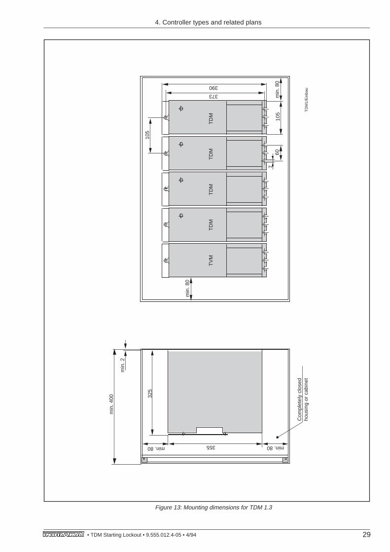
Figure 13: Mounting dimensions for TDM 1.3
30 TDM Starting Lockout • 9.555.012.4-05 •4/94 •
min
. 400
min
. 2
325
min. 80 355
Com
plet
ely
clos
edho
usin
g or
cab
inet
TV
M
74±0
,5
min
. 80
min
. 80
70 TD
M3/
4/6/
7Ein
bau
min. 80
7
373
390
TD
MT
DM
TD
MT
DM
TD
M
92±0
,5
105
60
4. Controller types and related plans
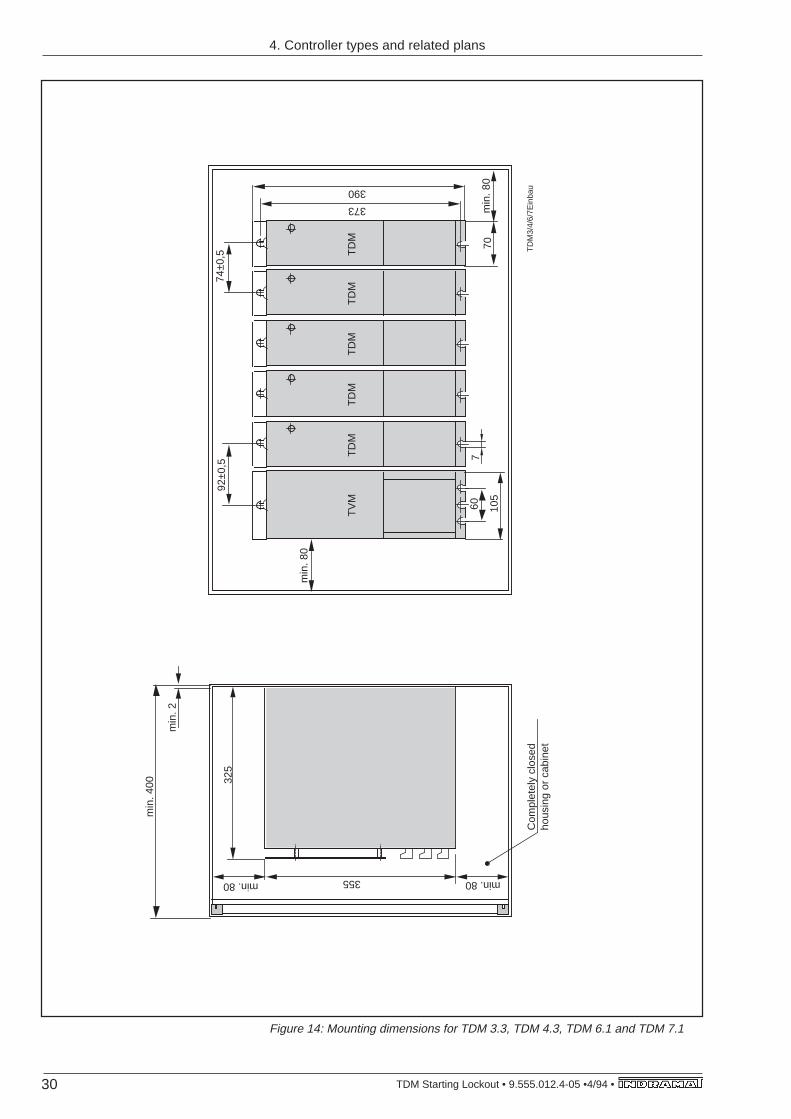
Figure 14: Mounting dimensions for TDM 3.3, TDM 4.3, TDM 6.1 and TDM 7.1
31• TDM Starting Lockout • 9.555.012.4-05 • 4/94
290,5
min
. 200
61
65,5
X74
F7
X73
290,5
min
. 200
61
65,5
8080
Standard modulecooling unit LE 5-024 (24 volt fan)
Cooling unit LE 5 (115 volt or 220 volt fan)
LE5
TDM …
24V-Connection
TDM …
Standard type:
Obsolete type:
4. Controller types and related plans
Figure 15: Fan dimensions for TDM 3.3, TDM 4.3, TDM 6.1 and TDM 7.1
32 TDM Starting Lockout • 9.555.012.4-05 •4/94 •
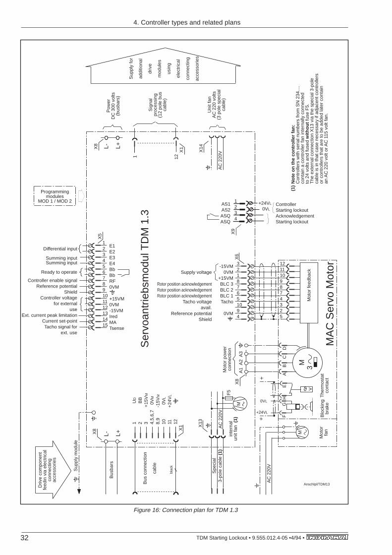
Figure 16: Connection plan for TDM 1.3
1 12
A1
A2
A3
X8
M
blac
k
X1
M
AC
220
V
X13
Spe
cial
3-po
le c
able
(1)
M3
MA
C S
ervo
Mot
or
F
GH
E
A
B
C
D
ϑ >
Blo
ckin
gbr
ake
The
rmos
tat
cont
act
Mot
or fe
edba
ck
+24VL
0VL
L- L+
L- L+
X8
X6
-15VM0VM
+15VMBLC 3BLC 2BLC 1Tacho
0VM
1
U
D
2
B
B3
+
15V
M
4,5,
6,7
0V
M
8,9
-15
VM
10
0V
L
11
+24
VL
12
X8
X14
AC
220
V
AC
220
V
E1E2E3E4BbBbRF0VM
+15VM0VM-15VMIredMATsense
X5
X1
F5
Anschlpl/TDM13
Bus
bars
Sup
ply
mod
ule
Sig
nal
proc
essi
ng(1
2 po
le b
us
cabl
e)
Sup
ply
for
addi
tiona
l
driv
e
mod
ules
usin
g
elec
tric
al
conn
ectin
g
acce
ssor
ies
Pow
erD
C 3
00 v
olts
(bus
bars
)
Mot
or p
ower
conn
ectio
n
Ser
voan
trie
bsm
odul
TD
M 1
.3
Uni
t fan
AC
220
vol
ts(3
pol
e sp
ecia
l ca
ble)
Mot
orfa
n
Bus
con
nect
ion
cabl
e
Driv
e co
mpo
nent
fe
edin
via
ele
ctric
al
conn
ectin
g ac
cess
orie
s
inte
rnal
unit
fan
(1)
Programming modules
MOD 1 / MOD 2
Not
e on
the
cont
rolle
r fa
n:C
ontr
olle
rs w
ith s
eria
l num
bers
from
SN
234
....
cont
ain
a co
ntro
ller
fan
inte
rnal
ly c
onne
cted
to 2
4 vo
lts a
nd fu
sed
with
out
fuse
F5.
The
ext
erna
l con
nect
ion
X13
via
the
spec
ial 3
-pol
e ca
ble
is in
that
cas
e ne
cess
ary
if ad
jace
nt c
ontr
olle
rs
or c
ontr
olle
rs th
at a
re to
be
adde
d la
ter
cont
ain
an A
C 2
20 v
olt o
r AC
115
vol
t fan
.
(1)
123456789101112131415
Differential input
Summing inputSumming input
Ready to operate
Controller enable signalReference potential
ShieldController voltage
for externaluse
Ext. current peak limitationCurrent set-pointTacho signal for
ext. use
32187651094
1211109874325
Supply voltage
Rotor position acknowledgementRotor position acknowledgementRotor position acknowledgement
Tacho voltageavail.
Reference potentialShield
ControllerStarting lockoutAcknowledgementStarting lockout
+24VL
0VL
X9
AS1AS2ASQASQ
1234
4. Controller types and related plans
33• TDM Starting Lockout • 9.555.012.4-05 • 4/94
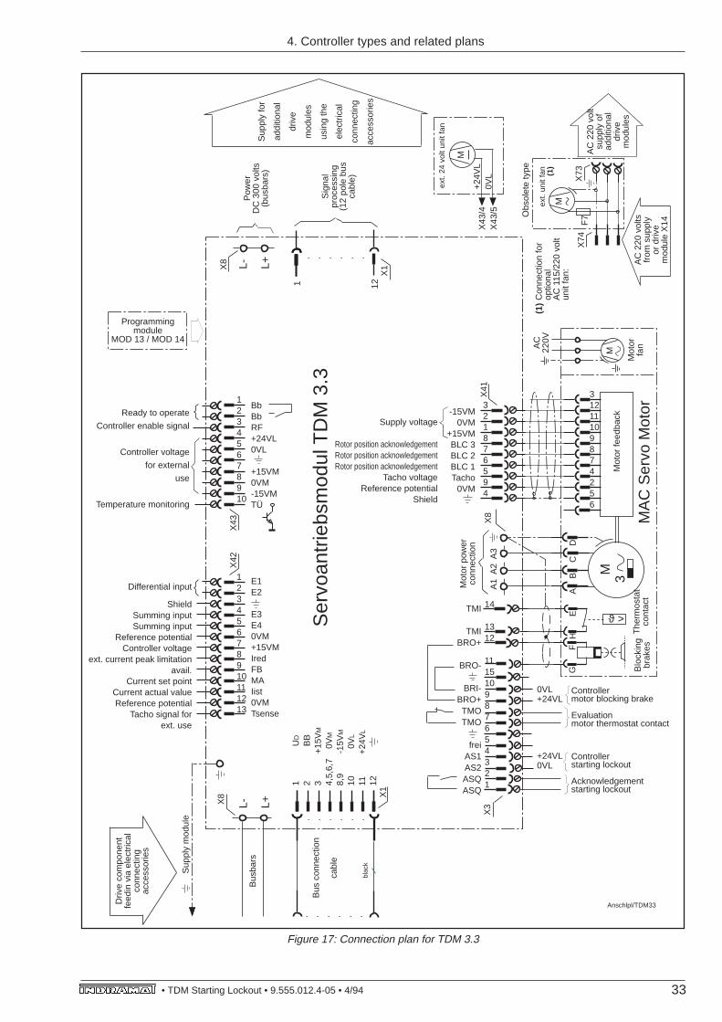
Figure 17: Connection plan for TDM 3.3
1 12bl
ack
X1
M
L- L+
L- L+
X8
1
U
D
2
B
B3
+
15V
M
4,5,
6,7
0V
M
8,9
-15
VM
10
0V
L
11
+24
VL
12
X8
X1
X42
X43
F7
X73
X74
Anschlpl/TDM33
Bus
bars
Sup
ply
mod
ule
Sig
nal
proc
essi
ng(1
2 po
le b
us
cabl
e)
Sup
ply
for
addi
tiona
l
driv
e
mod
ules
usin
g th
e
elec
tric
al
conn
ectin
g
acce
ssor
ies
Pow
erD
C 3
00 v
olts
(bus
bars
)
Ser
voan
trie
bsm
odul
TD
M 3
.3
AC
220
vol
tsfr
om s
uppl
yor
driv
em
odul
e X
14
Bus
con
nect
ion
cabl
e
Driv
e co
mpo
nent
fe
edin
via
ele
ctric
al
conn
ectin
g ac
cess
orie
s
AC
220
vol
tsu
pply
of
addi
tiona
l dr
ive
mod
ules
ext.
unit
fan
(1)
BbBbRF+24VL0VL
+15VM0VM-15VMTÜ
Programmingmodule
MOD 13 / MOD 14
12345678910
Ready to operate
Controller enable signal
Controller voltage
for external
use
Temperature monitoring
12345678910111213
Differential input
ShieldSumming inputSumming input
Reference potentialController voltage
ext. current peak limitationavail.
Current set pointCurrent actual valueReference potential
Tacho signal forext. use
E1E2
E3E40VM+15VMIredFBMAIist0VMTsense
M
ext.
24 v
olt u
nit f
an
Con
nect
ion
for
optio
nal
AC
115
/220
vol
tun
it fa
n:
(1)
+24
VL
0VL
X43
/4X
43/5
A1
A2
A3
X8
M3
MA
C S
ervo
Mot
or
G
FH
E
A
B
C
D
ϑ >
X3
Mot
or p
ower
conn
ectio
n
Blo
ckin
g br
akes
The
rmos
tat
cont
act
X41
Mot
or fe
edba
ck
AC
220V
Mot
orfa
n
M
321876594
31211109874256
-15VM0VM
+15VMBLC 3BLC 2BLC 1Tacho
0VM
Supply voltage
Rotor position acknowledgementRotor position acknowledgementRotor position acknowledgement
Tacho voltageReference potential
Shield
TMI
TMIBRO+
BRO-
BRI-BRO+TMOTMO
freiAS1AS2ASQASQ
14
1312
111510987654321
Controllermotor blocking brake
Evaluationmotor thermostat contact
Controllerstarting lockout
Acknowledgementstarting lockout
0VL+24VL
+24VL0VL
Obs
olet
e ty
pe
4. Controller types and related plans
34 TDM Starting Lockout • 9.555.012.4-05 •4/94 •
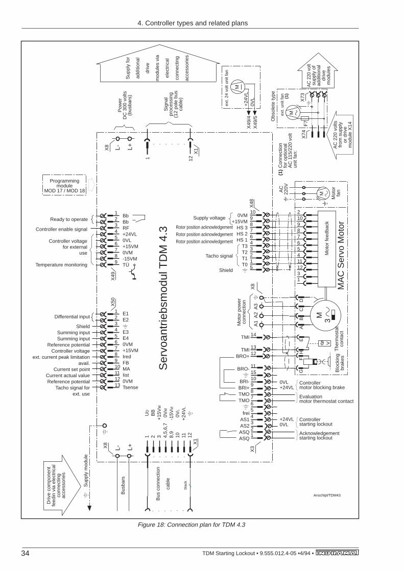
Figure 18: Connection plan for TDM 4.3
1 12bl
ack
X1
L- L+
L- L+
X8
1
U
D
2
B
B3
+
15V
M
4,5,
6,7
0V
M
8,9
-15
VM
10
0V
L
11
+24
VL
12
X8
X1
Anschlpl/TDM43Bus
bars
Sup
ply
mod
ule
Sig
nal
proc
essi
ng(1
2 po
le b
us
cabl
e)
Sup
ply
for
addi
tiona
l
driv
e
mod
ules
via
elec
tric
al
conn
ectin
g
acce
ssor
ies
Pow
erD
C 3
00 v
olts
(bus
bars
)
Ser
voan
trie
bsm
odul
TD
M 4
.3B
us c
onne
ctio
n
cabl
e
Driv
e co
mpo
nent
fe
edin
via
ele
ctric
al
conn
ectin
g ac
cess
orie
s
Programming module
MOD 17 / MOD 18
X50
X49
BbBbRF+24VL0VL+15VM0VM-15VMTÜ
123456789
Controller enable signal
Controller voltagefor external
use
Temperature monitoring
12345678910111213
Differential input
ShieldSumming inputSumming input
Reference potentialController voltage
ext. current peak limitationavail.
Current set pointCurrent actual valueReference potential
Tacho signal forext. use
E1E2
E3E40VM+15VMIredFBMAIist0VMTsense
A1
A2
A3
X8
M3
MA
C S
ervo
Mot
or
G
FH
E
A
B
C
D
X48
ϑ >
X3
Mot
or p
ower
conn
ectio
n
Blo
ckin
g br
akes
The
rmos
tat
cont
act
Mot
or fe
edba
ck
TMI
TMIBRO+
BRO-
BRI-BRI+TMOTMO
freiAS1AS2ASQASQ
14
1312
111510987654321
Controllermotor blocking brake
Evaluationmotor thermostat contact
Controllerstarting lockout
Acknowledgementstarting lockout
0VL+24VL
+24VL0VL
210987654111231
10987643215
0VM+15VM
HS 3HS 2HS 1
T3T2T1T0
Rotor position acknowledgement
Rotor position acknowledgement
Rotor position acknowledgement
Tacho signal
Shield
Supply voltage
AC
220V
Mot
or
fan
M
Ready to operate
M
F7
X73
X74
AC
220
vol
tsfr
om s
uppl
yor
driv
em
odul
e X
14
AC
220
vol
tsu
pply
of
addi
tiona
l dr
ive
mod
ules
ext.
unit
fan
(1)
M
ext.
24 v
olt u
nit f
an
Con
nect
ion
for
optio
nal
AC
115
/220
vol
tun
it fa
n:
(1)
+24
VL
0VL
X49
/4X
49/5 Obs
olet
e ty
pe
4. Controller types and related plans
35• TDM Starting Lockout • 9.555.012.4-05 • 4/94
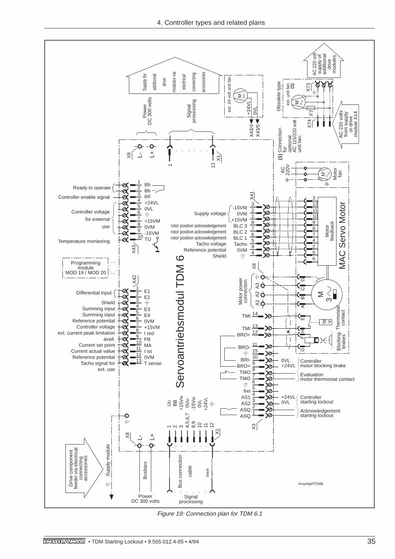
Figure 19: Connection plan for TDM 6.1
A1
A2
A3
X8
M3
MA
C S
ervo
Mot
or
G
FH
E
A
B
C
D
blac
k
X1
L- L+
L- L+
X8
ϑ >
1
U
D
2
B
B3
+
15V
M
4,5,
6,7
0V
M
8,9
-15
VM
10
0V
L
11
+24
VL
12
X8
X42
Anschlpl/TDM6
X3
Bus
bars
Sup
ply
mod
ule
Supp
ly fo
r
addi
tiona
l
drive
mod
ules
via
elec
trica
l
conn
ectin
g
acce
ssor
ies
Pow
erD
C 3
00 v
olts
Mot
or p
ower
conn
ectio
n
Ser
voan
trie
bsm
odul
TD
M 6
Blo
ckin
g br
akes
The
rmos
tat
cont
act
Bus
con
nect
ion
cabl
e
Programming module
MOD 19 / MOD 20
Driv
e co
mpo
nent
fe
edin
via
ele
ctric
al
conn
ectin
g ac
cess
orie
s
X41
Mot
or
feed
back
X43
1 12X
1
Sig
nal
proc
essi
ng
AC
220V
Mot
orfa
n
M
PowerDC 300 volts
Signalprocessing
321876594
31211109874256
-15VM0VM
+15VMBLC 3BLC 2BLC 1Tacho
0VM
Supply voltage
rotor position acknowledgementrotor position acknowledgementrotor position acknowledgement
Tacho voltageReference potential
Shield
TMI
TMIBRO+
BRO-
BRI-BRO+TMOTMO
freiAS1AS2ASQASQ
14
1312
111510987654321
Controllermotor blocking brake
Evaluationmotor thermostat contact
Controllerstarting lockout
Acknowledgementstarting lockout
0VL+24VL
+24VL0VL
12345678910
Controller enable signal
Controller voltage
for external
use
Temperature monitoring
BbBbRF+24VL0VL
+15VM0VM-15VMTÜ
ShieldSumming inputSumming input
Reference potentialController voltage
ext. current peak limitationavail.
Current set pointCurrent actual valueReference potential
Tacho signal forext. use
Differential input E1E2
E3E40VM+15VMI redFBMAI ist0VMT sense
Ready to operate
12345678910111213
M
F7
X73
X74
AC
220
vol
tsfr
om s
uppl
yor
driv
em
odul
e X
14
AC
220
vol
tsu
pply
of
addi
tiona
l dr
ive
mod
ules
ext.
unit
fan
(1)
M
ext.
24 v
olt u
nit f
an
Con
nect
ion
for
optio
nal
AC
115
/220
vol
tun
it fa
n:
(1)
+24
VL
0VL
X43
/4X
43/5
Obs
olet
e ty
pe
4. Controller types and related plans
36 TDM Starting Lockout • 9.555.012.4-05 •4/94 •
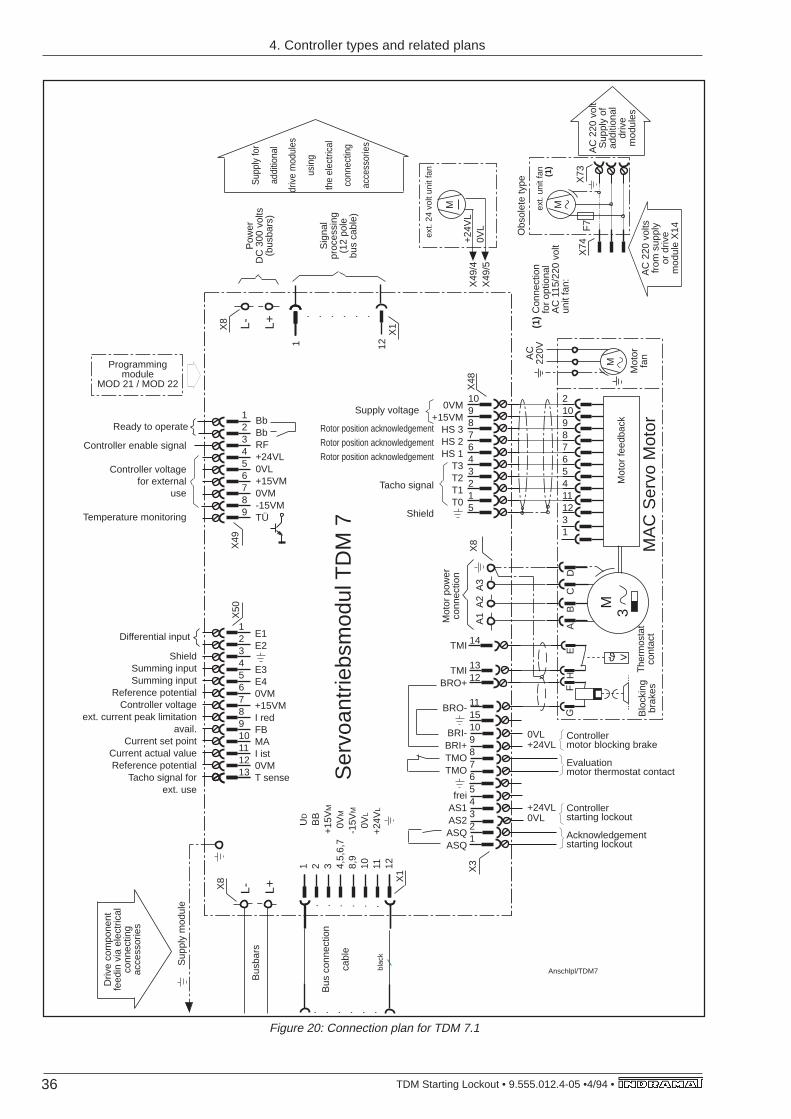
Figure 20: Connection plan for TDM 7.1
1 12
A1
A2
A3
X8
M3
MA
C S
ervo
Mot
or
G
FH
E
A
B
C
D
blac
k
X1
L- L+
L- L+
X8
X48
ϑ >
1
U
D
2
B
B3
+
15V
M
4,5,
6,7
0V
M
8,9
-15
VM
10
0V
L
11
+24
VL
12
X8
X1
X50
X49
Anschlpl/TDM7
X3
Bus
bars
Sup
ply
mod
ule
Sig
nal
proc
essi
ng(1
2 po
lebu
s ca
ble)
Sup
ply
for
addi
tiona
l
driv
e m
odul
es
usin
g
the
elec
trica
l
conn
ectin
g
acce
ssor
ies
Pow
erD
C 3
00 v
olts
(bus
bars
)
Mot
or p
ower
conn
ectio
n
Ser
voan
trie
bsm
odul
TD
M 7
Blo
ckin
gbr
akes
Ther
mos
tat
cont
act
Mot
or fe
edba
ck
Bus
con
nect
ion
cabl
e
Programming module
MOD 21 / MOD 22
Driv
e co
mpo
nent
fe
edin
via
ele
ctric
al
conn
ectin
g ac
cess
orie
s
123456789
Controller enable signal
Controller voltagefor external
use
Temperature monitoring
BbBbRF+24VL0VL+15VM0VM-15VMTÜ
TMI
TMIBRO+
BRO-
BRI-BRI+TMOTMO
freiAS1AS2ASQASQ
14
1312
111510987654321
Controllermotor blocking brake
Evaluationmotor thermostat contact
Controllerstarting lockout
Acknowledgementstarting lockout
0VL+24VL
+24VL0VL
ShieldSumming inputSumming input
Reference potentialController voltage
ext. current peak limitationavail.
Current set pointCurrent actual valueReference potential
Tacho signal forext. use
Differential input E1E2
E3E40VM+15VMI redFBMAI ist0VMT sense
Ready to operate
12345678910111213
210987654111231
10987643215
0VM+15VM
HS 3HS 2HS 1
T3T2T1T0
Rotor position acknowledgement
Rotor position acknowledgement
Rotor position acknowledgement
Tacho signal
Shield
Supply voltage
AC
220V
Mot
orfa
n
M
M
F7
X73
X74
AC
220
vol
ts
from
sup
ply
or d
rive
mod
ule
X14
AC
220
vol
tS
uppl
y of
addi
tiona
ldr
ive
mod
ules
ext.
unit
fan
(1)
M
ext.
24 v
olt u
nit f
an
Con
nect
ion
for
optio
nal
AC
115
/220
vol
tun
it fa
n:
(1)
+24
VL
0VL
X49
/4X
49/5
Obs
olet
e ty
pe
4. Controller types and related plans

37• TDM Starting Lockout • 9.555.012.4-05 • 4/94

Indramat