Embed Size (px)
Citation preview

FS-B35XX Series Start-up Guide 0
Start-up Guide
FieldServer FS-B35XX Series
MSAsafety.com
Document Revision: 3.A
T18602
APPLICABILITY & EFFECTIVITY Effective for all systems manufactured after January 2021.

FS-B35XX Series Start-up Guide 2
MSA Safety
1991 Tarob Court
Milpitas, CA 95035
Website: www.MSAsafety.com
U.S. Support Information:
+1 408 964-4443
+1 800 727-4377
Email: [email protected]
EMEA Support Information:
+31 33 808 0590
Email: [email protected]

FS-B35XX Series Start-up Guide 3
Table of Contents
1 FieldServer FS-B35 Series Description .......................................................................................... 5 1.1 Certifications ............................................................................................................................. 5
1.1.1 BTL Mark – BACnet Testing Laboratory .................................................................................. 5 1.1.2 LonMark Certification ............................................................................................................... 5
2 Equipment Setup .............................................................................................................................. 6 2.1 Supplied Equipment ................................................................................................................. 6 2.2 Mounting ................................................................................................................................... 7 2.3 Physical Dimensions ................................................................................................................ 8 2.4 Wiring ........................................................................................................................................ 8
3 Connecting to the Device ................................................................................................................ 9 3.1 RS-232 Connection .................................................................................................................. 9 3.2 RS-485 Connection .................................................................................................................. 9 3.3 Ethernet Connection ................................................................................................................. 9
3.3.1 Ethernet Port Behavior (N1 & N2) .......................................................................................... 10
4 Operation ......................................................................................................................................... 11 4.1 Power-up the Device .............................................................................................................. 11 4.2 Connect the PC to the FieldServer via Ethernet Port ............................................................. 11 4.3 Using FieldServer Toolbox to Find the IP Address ................................................................ 11 4.4 Assign Network Settings for the FieldServer .......................................................................... 12
5 Configuring the FieldServer .......................................................................................................... 13 5.1 Retrieve the Sample Configuration File .................................................................................. 13 5.2 Change the Configuration File to Meet the Application .......................................................... 13 5.3 Load the Updated Configuration File ...................................................................................... 14
5.3.1 Using the FS-GUI to Load a Configuration File ..................................................................... 14 5.3.2 Retrieve the Configuration File for Modification or Backup .................................................... 15
5.4 Test and Commission the FieldServer ................................................................................... 16
6 Troubleshooting ............................................................................................................................. 17 6.1 Communicating with the FieldServer Over the Network ........................................................ 17 6.2 Take a Diagnostic Capture ..................................................................................................... 18 6.3 Securing FieldServer with Password ...................................................................................... 20 6.4 LED Functions ........................................................................................................................ 21
6.4.1 LED Identification and Function ............................................................................................. 21 6.4.2 LED Interpretation .................................................................................................................. 22 6.4.3 LED Power-up Sequence ....................................................................................................... 22
6.5 Internet Browser Software Support ........................................................................................ 22
7 Additional Information ................................................................................................................... 23 7.1 Supplied Connector Kit (FS-8915-11) .................................................................................... 23 7.2 Specifications.......................................................................................................................... 24
8 Limited 2 Year Warranty ................................................................................................................ 25

FS-B35XX Series Start-up Guide 4
List of Figures
Figure 1: FieldServer FS-B35XX Series Showing Din Mounting Option ...................................................... 7 Figure 2: FieldServer FS-B35XX Series Showing Dimensions .................................................................... 8 Figure 3: RS-232 Connection Ports .............................................................................................................. 9 Figure 4: RS-435 Connection Ports .............................................................................................................. 9 Figure 5: Ethernet Connection Ports ............................................................................................................. 9 Figure 6: FieldServer Toolbox ..................................................................................................................... 11 Figure 7: Changing IP Address via FS-GUI ................................................................................................ 12 Figure 8: FS-GUI File Transfer.................................................................................................................... 13 Figure 9: FS-GUI Loading Files .................................................................................................................. 14 Figure 10: Retrieve Configuration File ........................................................................................................ 15 Figure 11: FS-GUI Connections .................................................................................................................. 16 Figure 12: FS-GUI Passwords Page ........................................................................................................... 20 Figure 13: Password Recovery Page ......................................................................................................... 20 Figure 14: FieldServer Connector ............................................................................................................... 23 Figure 15: Specifications ............................................................................................................................. 24

Description
FS-B35XX Series Start-up Guide 5
1 FieldServer FS-B35 Series Description
The FieldServer FS-B35 Series is a high performance, cost effective Building and Industrial Automation
multi-protocol gateway providing protocol translation between serial, Ethernet, and LonWorks1 devices and
networks.
NOTE: For troubleshooting assistance refer to Section 6, or any of the troubleshooting
appendices in the related driver supplements. Check the MSA Safety website for technical
support resources and the latest versions of documentation that may be of assistance.
1.1 Certifications
1.1.1 BTL Mark – BACnet2 Testing Laboratory
1.1.2 LonMark Certification
1 LonWorks is a registered trademark of Echelon Corporation. 2 BACnet is a registered trademark of ASHRAE.
The BTL Mark is a symbol that indicates that a product has passed a series of rigorous tests conducted by an independent laboratory which verifies that the product correctly implements the BACnet features claimed in the listing. The mark is a symbol of a high-quality BACnet product.
Go to www.BACnetInternational.net for more information about the BACnet Testing Laboratory. Click here for the BACnet PIC Statement.
LonMark International is the recognized authority for certification, education, and promotion of interoperability standards for the benefit of manufacturers, integrators and end users. LonMark International has developed extensive product certification standards and tests to provide the integrator and user with confidence that products from multiple manufacturers utilizing LonMark devices work together. MSA Safety has more LonMark Certified gateways than any other gateway manufacturer, including the ProtoCessor, ProtoCarrier and ProtoNode for OEM applications and the full featured, configurable gateways.

Equipment Setup
FS-B35XX Series Start-up Guide 6
2 Equipment Setup
2.1 Supplied Equipment
FS-B35XX Series FieldServer
• Preloaded with Modbus RTU driver, SMT Ethernet driver and any other drivers ordered. A sample
configuration file is also pre-loaded onto the FieldServer.
• All instruction manuals, driver manuals, configuration manuals and support utilities are available on
the USB drive provided in the optional accessory kit, or on the MSA Safety website.
USB Flash Drive loaded with:
o FS-B35XX Series Start-up Guide
o FieldServer Configuration Manual
o All FieldServer Driver Manuals
o Support Utilities
o Any additional folders related to special files configured
for a specific FieldServer
o Additional components as required - see Driver Manual Supplement for details
Accessories:
o DB9F/RJ45 Connection Adapter (Part # FS-8917-02)
o Adapter for hyperterminal connection to the Sys Port (Part # FS8917-26)
o Power Supply (Part # 69196)
o Detachable Power Cord (Part # 53029)
o 7 pin mini connector (RS-485) (Part # 59232)
o 5 pin mini connector (Power) (Part # 59231)
o 2 pin mini connector – High Temp (LonWorks® connection) (Part # 59230)
o Self-Adhesive feet (Part # 69178)
o Small accessory kit containing four unpinned DB9 connectors (Part # 8915-11)

Equipment Setup
FS-B35XX Series Start-up Guide 7
2.2 Mounting
The following mounting options are available:
• Wall or panel.
• Free standing or table.
• DIN rail (Part # FS-8915-30) - not included.
NOTE: Install only as instructed, failure to follow the installation guidelines or using screws
without the DIN rail mounting bracket could result in permanent damage to the product.
NOTE: If the FieldServer is removed from the din rail, use the original screws to reattach. Longer screws will damage the FieldServer.
Figure 1: FieldServer FS-B35XX Series Showing Din Mounting Option

Equipment Setup
FS-B35XX Series Start-up Guide 8
2.3 Physical Dimensions
2.4 Wiring
The power socket is a “screw terminal” type. It is recommended to use of the power supply sent with the
unit. If an alternative power supply is desired, select an external power supply that has been certified for
safety for the correct destination country and an output rating that is considered acceptable. Refer to
Section 7.2 for detailed specifications.
NOTE: USE COPPER CONDUCTORS ONLY.
Figure 2: FieldServer FS-B35XX Series Showing Dimensions
Installation
FS-B35XX Series Start-up Guide 9
3 Connecting to the Device
3.1 RS-232 Connection
Connect a RJ-45 cable (A) directly between Port P1/Port P2 and the remote RS-232 device. If using a
custom-built cable, make sure that the pinout on the FieldServer side of the cable is limited to the use of
pins 2(TX), 3(RX) and 5(GND).
NOTE: The Sys Port is for diagnostic use only and should not be used to connect to a Node.
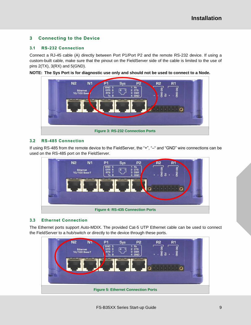
3.2 RS-485 Connection
If using RS-485 from the remote device to the FieldServer, the “+”, “–“ and “GND” wire connections can be
used on the RS-485 port on the FieldServer.
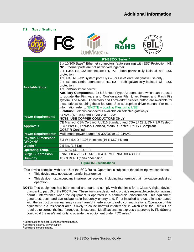
3.3 Ethernet Connection
The Ethernet ports support Auto-MDIX. The provided Cat-5 UTP Ethernet cable can be used to connect
the FieldServer to a hub/switch or directly to the device through these ports.
Figure 3: RS-232 Connection Ports
Figure 4: RS-435 Connection Ports
Figure 5: Ethernet Connection Ports

Installation
FS-B35XX Series Start-up Guide 10
3.3.1 Ethernet Port Behavior (N1 & N2)
The N1 and N2 Ethernet ports share an Ethernet stack. Therefore, the IP addresses of N1 and N2 must be
on separate subnets and must be connected to separate networks.
There is only 1 Gateway IP Address in the FS-B35XX. This means that when using both N1 and N2 Ethernet
ports simultaneously, only 1 Ethernet port can connect to a larger network through the Gateway IP Address
while the other is limited to a local network.
In the configuration file of the FS-B35XX, the choice of N1 or N2 is irrelevant. As a server, the FS-B35XX
will accept messages from either N1 or N2 port. As a client, the FS-B35XX will choose the correct port to
transmit a message based on the IP address of the remote device.

Operation
FS-B35XX Series Start-up Guide 11
4 Operation
4.1 Power-up the Device
• Apply power to the device. Ensure that the power supply used complies with
the specifications provided in 7.2.
• The power light should burn a steady green when the FieldServer is powered
up. Refer to Section 6.4 for more information on the various LED functions.
4.2 Connect the PC to the FieldServer via Ethernet Port
• The Ethernet ports support Auto-MDIX. The provided Cat-5 UTP Ethernet cable can be used to
connect the FieldServer to a hub/switch or directly to the device through either of the N1 or N2
ports.
• It is important that the PC/Laptop is on the same subnet as the FieldServer.
• If connecting 2 FieldServers together using the N1 and N2 ports, the ports need to be on different
subnets. The default IP Address on the FieldServer N1 port is 192.168.2.101 and the N2 port is
192.168.3.101. Refer to Section 3.3.1 and the FieldServer Toolbox Manual.
4.3 Using FieldServer Toolbox to Find the IP Address
• Check that a Cat-5 Ethernet cable (straight through or cross-over) is connected between the local
PC and FieldServer or the local PC is connected to the same subnet as the FieldServer.
• Ensure that FieldServer Toolbox is loaded onto the local PC. Otherwise, download the
FieldServer-Toolbox.zip via the MSA Safety website.
• Extract the executable file and complete the installation.
• Double click on the FS Toolbox Utility.
• Check the FieldServer IP Addresses from the device listings.
• Type the appropriate IP Address into the browser address bar to move onto registering the
FieldServer (Section 4.4).
Figure 6: FieldServer Toolbox

Operation
FS-B35XX Series Start-up Guide 12
4.4 Assign Network Settings for the FieldServer
• From the FS-GUI landing page, click on “Setup” to expand the navigation tree and then select
“Network Settings” to access the IP Settings menu. (Figure 7)
• Modify the IP Address (N1 IP Address field) of the FieldServer Ethernet port.
• If necessary, change the Netmask (N1 Netmask field).
• If necessary, change the IP Gateway (Default Gateway field).
NOTE: Do not change the DHCP Server State (N1 DHCP Server State field).
NOTE: If the FieldServer is connected to a managed switch/router, the IP Gateway of the
FieldServer should be set to the IP Address of that managed switch/router.
• Click the “System Restart” button at the bottom of the page to apply changes and restart the
FieldServer.
• Unplug Ethernet cable from PC and connect it to the network switch or router.
• Record the IP Address assigned to the FieldServer for future reference.
NOTE: The SMC Cloud button (see Figure 7) allows users to connect to the SMC
Cloud, MSA Safety’s device cloud solution for IIoT. The SMC Cloud enables secure remote
connection to field devices through a FieldServer and its local applications for
configuration, management, maintenance. For more information about the SMC Cloud,
refer to the SMC Cloud Start-up Guide.
Figure 7: Changing IP Address via FS-GUI

Configuring the Gateway
FS-B35XX Series Start-up Guide 13
5 Configuring the FieldServer
5.1 Retrieve the Sample Configuration File
The configuration of the FieldServer is provided to the FieldServer’s operating system via a comma-delimited file called “CONFIG.CSV”.
If a custom configuration was ordered, the FieldServer will be programmed with the relevant device registers in the Config.csv file for the first time start-up. If not, the product is shipped with a sample config.csv that shows an example of the drivers ordered.
• In the main menu of the FS-GUI screen, go to “Setup”, then “File Transfer”, and finally “Retrieve”.
• Click on “config.csv”, and open or save the file.
5.2 Change the Configuration File to Meet the Application
Refer to the FieldServer Configuration Manual in conjunction with the Driver supplements for information on configuring the FieldServer.
Figure 8: FS-GUI File Transfer

Configuring the Gateway
FS-B35XX Series Start-up Guide 14
5.3 Load the Updated Configuration File
5.3.1 Using the FS-GUI to Load a Configuration File
• In the main menu of the FS-GUI screen, click “Setup”, then “File Transfer” and finally “Update”.
• Browse and select the .csv file, open, then click “Submit”.
• Once download is complete, a message bar will appear confirming that the configuration was
updated successfully.
• Click the System Restart Button to put the new file into operation. Note that it is possible to do
multiple downloads to the FieldServer before resetting it.
NOTE: It is possible to do multiple downloads to the FieldServer before resetting it.
Figure 9: FS-GUI Loading Files

Configuring the Gateway
FS-B35XX Series Start-up Guide 15
5.3.2 Retrieve the Configuration File for Modification or Backup
To get a copy of the configuration file for modifying or backing up a configuration on a local computer, do the following:
• In the main menu of the FS-GUI screen, click “Setup”, then “File Transfer”.
• Click the “config.csv” link under the “Retrieve” heading in the middle section of the screen.
o The file will automatically download to the web browser’s default download location.
• Edit or store the file as desired.
NOTE: Before using any backup configuration file to reset the configuration settings, check that
the backup file is not an old version.
Figure 10: Retrieve Configuration File

Configuring the Gateway
FS-B35XX Series Start-up Guide 16
5.4 Test and Commission the FieldServer
• Connect the FieldServer to the third party device(s), and test the application.
• From the main menu of the FS-GUI click on “View”, then “Connections” to see the number of
messages on each protocol.
NOTE: For troubleshooting assistance refer to Section 6, or any of the troubleshooting
appendices in the related driver supplements and configuration manual. MSA Safety also
offers a technical support page on the MSA Safety website, which contains a significant
number of resources and the latest versions of documentation that may be of assistance.
Figure 11: FS-GUI Connections

Troubleshooting
FS-B35XX Series Start-up Guide 17
6 Troubleshooting
6.1 Communicating with the FieldServer Over the Network
• Confirm that the network cabling is correct.
• Confirm that the computer network card is operational and correctly configured.
• Confirm that there is an Ethernet adapter installed in the software configuration, and that it is
configured to run the TCP/IP protocol.
• Open Command Prompt.
• Type in “ipconfig”.
• The account settings should be displayed.
• Ensure that the IP address is on the same Subnet of the FieldServer.
o Default N1 IP Address is 192.168.2.101
o Default N2 IP Address is 192.168.3.101
• The IP address of the FieldServer can be changed using the FS-GUI. Refer to the FieldServer FS-
GUI manual for more information.

Troubleshooting
FS-B35XX Series Start-up Guide 18
6.2 Take a Diagnostic Capture
When there is a problem on-site that cannot easily be resolved, perform a Diagnostic Capture before
contacting support. Once the Diagnostic Capture is complete, email it to technical support. The
Diagnostic Capture will accelerate diagnosis of the problem.
NOTE: While all necessary documentation is shipped with the FieldServer on the USB flash drive,
these documents are constantly being updated. Newer versions may be available on the
MSA Safety website.
• Ensure that FieldServer Toolbox is loaded onto the local PC. Otherwise, download the
FieldServer-Toolbox.zip via the MSA Safety website.
• Extract the executable file and complete the installation.
• Connect a standard Cat-5 Ethernet cable between the PC and FieldServer.
• Double click on the FS Toolbox Utility.
• Step 1: Take a Log
o Click on the diagnose icon of the desired device

Troubleshooting
FS-B35XX Series Start-up Guide 19
o Ensure “Full Diagnostic" is selected (this is the default)
NOTE: If desired, the default capture period can be changed.
o Click on the Start Diagnostic button
o Wait for the capture period to finish and the Diagnostic Test Complete window will appear
• Step 2: Send Log
o Once the diagnostic test is complete, a .zip file is saved on the PC
o Choose “Open” to launch explorer and have it point directly at the correct folder
o Send the Diagnostic zip file to technical support

Troubleshooting
FS-B35XX Series Start-up Guide 20
6.3 Securing FieldServer with Password
Access to the FieldServer can be restricted by enabling a password on the FS-GUI Passwords page – click
Setup and then Passwords in the navigation panel. There are 2 access levels defined by 2 account names:
Admin and User.
• The Admin account has unrestricted access to the FieldServer.
• The User account can view any FieldServer information but cannot make any changes or restart
the FieldServer.
The password needs to be a minimum of eight characters and is case sensitive.
If the password is lost, click cancel on the password authentication popup window, and e-mail the password
recovery token to [email protected] to receive a temporary password from the FieldServer
support team. This will allow access to the FieldServer in order to set a new password.
Figure 12: FS-GUI Passwords Page
Figure 13: Password Recovery Page

Troubleshooting
FS-B35XX Series Start-up Guide 21
6.4 LED Functions
6.4.1 LED Identification and Function
Light Description
Power The power light should show steady green at all times when the FieldServer is powered.
Run
The run light indicates that the FieldServer firmware is running. It should flash green
once per second once the FieldServer has booted up. Note that it may take a while from
power up to boot up the FieldServer if the loaded configuration is particularly large.
HSB Active
Two FieldServers can be connected in a hot standby configuration to ensure reliability
in the case of a vital system failure on the Active FieldServer. Refer to the FieldServer
Configuration Manual for more information. A steady amber light indicates which
FieldServer in a hot standby pair is currently active.
Node
Offline
An amber light will burn when a configured node in the FieldServer is detected as being
offline. See Node overview screen in the remote user interface for further details
Config Err An amber light will burn if a configuration error exists in the active configuration. See
Error screen in the remote user interface for description of configuration error.
Comm Err The communications light will turn amber if there is a communications error detected.
To establish the cause of the error, go to the error screen of the FS-GUI interface.
Sys Err
The system light will burn red if there is a system error on the FieldServer. If this occurs,
immediately report the related “system error” shown in the error screen of the FS-GUI
interface to technical support for evaluation.
RS-232
Lights
(P1, P2)
These lights are related to the RS-232 serial ports provided on the FieldServer. The Rx
(Receive) light will flash red if the FieldServer is receiving data. The Tx (Transmit) light
will flash red if the FieldServer is sending data. The frequency of the flashing is directly
related to the frequency of data transfer.
RS-485
Lights
(R1, R2)
These lights are related to the RS-485 serial ports provided on the FieldServer. The Rx
(Receive) light will flash red if the FieldServer is receiving data. The Tx (Transmit) light
will flash red if the FieldServer is sending data. (Note that due to the nature of 2-wire
RS-485 the Rx light will flash every time the Tx light flashes). The frequency of the
flashing is directly related to the frequency of data transfer.
Ethernet
Lights
(N1,N2)
These lights are related to the two Ethernet network ports provided on the FieldServer.
The 10/100 light indicates connection speed. LED Off = 10; LED On = 100. The Act
(Activity) light indicates link and activity on the network. The LED will be Off if there is
no link, On if there is a link and blinking represents activity on the link.
LonWorks® This light indicates activity on the LonWorks® port. Refer to Section 6.4.2 for behavior
interpretation.

Troubleshooting
FS-B35XX Series Start-up Guide 22
6.4.2 LED Interpretation
Sys Err
HSB Active
Com Err
Config Err
Active Node
Offline Run PWR Description
FLASH ON Indicating Power.
ON FLASH ON One of the configured nodes
is offline.
ON FLASH ON FieldServer is active in a Hot
Standby configuration.
ON FLASH ON System Error. Contact
support.
OFF FLASH ON RELEASE DCC running.
ON FLASH ON Configuration error.
FLASH FLASH ON Demo Mode.
Flash Once
Flash Once
Flash Once
Flash Once
Flash Once
Flash Once
Flash Once
ON Sequence of LEDs – shows a
boot cycle attempt.
LonWorks LED Interpretation:
Explicit Implicit – Not Commissioned Implicit – Commissioned
Off Flashing Off
6.4.3 LED Power-up Sequence
1. Start-up: All LED’s on.
2. Load Bios: Run LED will switch off after completion.
3. Load U-boot: HSB Active LED will switch off after completion.
4. Load Linux Kernel: Node Offline LED will switch off after completion.
5. Load Ethernet driver: Config LED will switch off after completion.
6. Load Flash File: Sys LED will switch off after completion.
7. Load Application Firmware: Sys Error LED will switch off after completion.
6.5 Internet Browser Software Support
The following web browsers are supported:
• Chrome Rev. 57 and higher
• Firefox Rev. 35 and higher
• Microsoft Edge Rev. 41 and higher
• Safari Rev. 3 and higher
NOTE: Internet Explorer is no longer supported as recommended by Microsoft.
NOTE: Computer and network firewalls must be opened for Port 80 to allow FieldServer GUI to
function.

Additional Information
FS-B35XX Series Start-up Guide 23
7 Additional Information
7.1 Supplied Connector Kit (FS-8915-11)
The following connector is supplied to facilitate RS-232 communications on the RJ-45 RS-232 port. The
table in the diagram shows the functions applied to each of the RJ-45 pins by the FieldServer to assist in
determination of the required pinout configuration for connection to the third party device.
NOTE: FS-B35XX Series RS-232 numbering convention is reverse to the 10BaseT numbering.
FS-8917-02
WIRE LIST
Figure 14: FieldServer Connector
Additional Information
FS-B35XX Series Start-up Guide 24
7.2 Specifications
FS-B35XX Series 3
Available Ports
2 x 10/100 BaseT Ethernet connectors (auto sensing) with ESD Protection: N1, N2. Ethernet ports are not networked together. 2 x RJ45 RS-232 connectors: P1, P2 – both galvanically isolated with ESD protection. 1 x RJ45 RS-232 System port: Sys – For FieldServer diagnostic use only. 2 x RS-485 Serial connectors: R1, R2 – both galvanically isolated with ESD protection. 1 x LonWorks® connector. Auxiliary Components: 2x USB Host (Type A) connectors which can be used to update the Firmware and Configuration File, Linux Kernel and Flash File system. The Node ID selectors and LonWorks® Service button are available for those drivers requiring these features. See appropriate driver manual. For more information refer to “ENOTE – Loading Files using USB”. Fieldbus: Fieldbus connectors available on selected gateways.
Power Requirements 24 VAC (+/- 10%) and 12-30 VDC, 12W NOTE: USE COPPER CONDUCTORS ONLY
Approvals CE Marked, CSA Certified: UL916 Standard and CSA @ 22.2, DNP 3.0 Tested, FCC: Part 15, LonMark Certified, Modbus Tested, RoHS3 Compliant, GOST-R Certified
Power Requirements4 Multi-mode power adapter: 9-30VDC or 12-24VAC
Physical Dimensions (WxDxH) 5 6.3 W x 5.4 D x 1.95 H inches (16 x 13.7 x 5 cm)
Weight 4 2.5 lbs. (1.5 Kg)
Operating Temp. 0 – 60°C (32 – 140°F)
Surge Suppression EN61000-4-2 ESD EN61000-4-3 EMC EN61000-4-4 EFT
Humidity 10 - 90% RH (non-condensing)
Figure 15: Specifications
“This device complies with part 15 of the FCC Rules. Operation is subject to the following two conditions:
• This device may not cause harmful interference
• This device must accept any interference received, including interference that may cause undesired operation.
NOTE: This equipment has been tested and found to comply with the limits for a Class A digital device, pursuant to part 15 of the FCC Rules. These limits are designed to provide reasonable protection against harmful interference when the equipment is operated in a commercial environment. This equipment generates, uses, and can radiate radio frequency energy and, if not installed and used in accordance with the instruction manual, may cause harmful interference to radio communications. Operation of this equipment in a residential area is likely to cause harmful interference in which case the user will be required to correct the interference at his expense. Modifications not expressly approved by FieldServer could void the user's authority to operate the equipment under FCC rules.”
3 Specifications subject to change without notice. 4 Excluding external power supply. 5 Excluding mounting tabs.

Limited Warranty
FS-B35XX Series Start-up Guide 25
8 Limited 2 Year Warranty
MSA Safety warrants its products to be free from defects in workmanship or material under normal use and
service for two years after date of shipment. MSA Safety will repair or replace any equipment found to be
defective during the warranty period. Final determination of the nature and responsibility for defective or
damaged equipment will be made by MSA Safety personnel.
All warranties hereunder are contingent upon proper use in the application for which the product was
intended and do not cover products which have been modified or repaired without MSA Safety’s approval
or which have been subjected to accident, improper maintenance, installation or application; or on which
original identification marks have been removed or altered. This Limited Warranty also will not apply to
interconnecting cables or wires, consumables or to any damage resulting from battery leakage.
In all cases MSA Safety’s responsibility and liability under this warranty shall be limited to the cost of the
equipment. The purchaser must obtain shipping instructions for the prepaid return of any item under this
warranty provision and compliance with such instruction shall be a condition of this warranty.
Except for the express warranty stated above, MSA Safety disclaims all warranties with regard to the
products sold hereunder including all implied warranties of merchantability and fitness and the express
warranties stated herein are in lieu of all obligations or liabilities on the part of MSA Safety for damages
including, but not limited to, consequential damages arising out of/or in connection with the use or
performance of the product.