Embed Size (px)
Citation preview
w w w . t n b . c a A1
Star Teck ® Teck and Tray Cable Fittings
Table of Contents
The Whole Family. ............................................................................A2–A3
Specifications .................................................................................. A4–A5
Hazardous Locations – CEC Classifications ..................................... A6–A9
Hazardous Locations – Class, Zone and Division Certifications ............. A10
Quick Reference ....................................................................................A11
Star Teck® (ST) – Series Fittings for Teck and ACWU Cable ...........A12–A13
Star Teck XP® (STX) – Hazardous Location
Series Fittings for Teck Cable ....................................................... A14–A15
Star Teck Extreme® (STE) – Series Fittings
for Teck Cable and ACWU Cable .............................................. A16–A17
Bond Star® – Grounding Locknut .................................................. A18–A19
Star Teck Extreme DirectorTM (STED) – Teck Cable Fittings .......... A20–A21
Star Teck Extreme XP® (STEX) – Hazardous Location
Series Fittings for Teck Cable ................................................. A22–A23
10464 Series – Watertight Fittings / ACWU .......................................... A24
90º Watertight Fittings and Non-Watertight Teck Cable Fittings ............A25
Tray StarTM HLT Series – Hazardous Location
Fittings for Tray Cable ...........................................................................A26
Flexible Cord and Cable Fittings ............................................................A27
Accessories ..........................................................................................A28
w w w . t n b . c aA2
Teck and Tray Cable FittingsStar Teck ®
The Whole FamilyStar Teck® Cable Fittings – A tradition of industry firsts
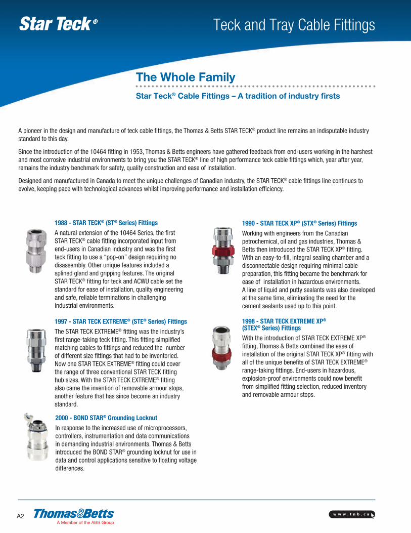
1988 - STAR TECK® (ST® Series) Fittings
A natural extension of the 10464 Series, the first STAR TECK® cable fitting incorporated input from end-users in Canadian industry and was the first teck fitting to use a “pop-on” design requiring no disassembly. Other unique features included a splined gland and gripping features. The original STAR TECK® fitting for teck and ACWU cable set the standard for ease of installation, quality engineering and safe, reliable terminations in challenging industrial environments.
1990 - STAR TECK XP® (STX® Series) Fittings
Working with engineers from the Canadian petrochemical, oil and gas industries, Thomas & Betts then introduced the STAR TECK XP® fitting. With an easy-to-fill, integral sealing chamber and a disconnectable design requiring minimal cable preparation, this fitting became the benchmark for ease of installation in hazardous environments. A line of liquid and putty sealants was also developed at the same time, eliminating the need for the cement sealants used up to this point.
1997 - STAR TECK EXTREME® (STE® Series) Fittings
The STAR TECK EXTREME® fitting was the industry’s first range-taking teck fitting. This fitting simplified matching cables to fittings and reduced the number of different size fittings that had to be inventoried. Now one STAR TECK EXTREME® fitting could cover the range of three conventional STAR TECK fitting hub sizes. With the STAR TECK EXTREME® fitting also came the invention of removable armour stops, another feature that has since become an industry standard.
1998 - STAR TECK EXTREME XP®
(STEX® Series) Fittings
With the introduction of STAR TECK EXTREME XP® fitting, Thomas & Betts combined the ease of installation of the original STAR TECK XP® fitting with all of the unique benefits of STAR TECK EXTREME® range-taking fittings. End-users in hazardous, explosion-proof environments could now benefit from simplified fitting selection, reduced inventory and removable armour stops.
2000 - BOND STAR® Grounding Locknut
In response to the increased use of microprocessors, controllers, instrumentation and data communications in demanding industrial environments. Thomas & Betts introduced the BOND STAR® grounding locknut for use in data and control applications sensitive to floating voltage differences.
A pioneer in the design and manufacture of teck cable fittings, the Thomas & Betts STAR TECK® product line remains an indisputable industry standard to this day.
Since the introduction of the 10464 fitting in 1953, Thomas & Betts engineers have gathered feedback from end-users working in the harshest and most corrosive industrial environments to bring you the STAR TECK® line of high performance teck cable fittings which, year after year, remains the industry benchmark for safety, quality construction and ease of installation.
Designed and manufactured in Canada to meet the unique challenges of Canadian industry, the STAR TECK® cable fittings line continues to evolve, keeping pace with technological advances whilst improving performance and installation efficiency.

w w w . t n b . c a A3
Teck and Tray Cable FittingsStar Teck ®
The Whole FamilyStar Teck Extreme Director™ (STED) – Teck Cable Fittings
STAR TECK EXTREME DIRECTOR™ Cable Fitting The latest industry first.
Terminating teck cable can be a time consuming process, especially when angle adjustments are required. Current termination methods such as 90-degree elbows and LB conduit bodies take up a lot of space and lack flexibility.
To address these issues, Thomas & Betts is proud to introduce its latest “industry first” - the STAR TECK EXTREME DIRECTORTM fitting, the electrical industry’s first truly adjustable, range-taking fitting.
Compared to traditional 90-degree termination methods, the STAR TECK EXTREME DIRECTORTM fitting adjusts from 90 to 180 degrees. A full circular bore makes cable insertion trouble-free. Alignment guides serve as handy reference points for aligning installed fittings at the same angle.
What’s more, the STAR TECK EXTREME DIRECTORTM fitting requires no disassembly prior to installation and can also be easily disconnected.
Revolutionary
w w w . t n b . c aA4
Teck and Tray Cable FittingsStar Teck ®
Please noteThe excerpts and other material herein, whether relating to the National Electrical Code, the Underwriters Laboratories, Inc. listing, to industry practice or otherwise, are not intended to provide all relevant information required for use and installation. Reference to original or primary source material and data is mandatory before any application or use is made of the product.
CSA CertifiedCSA Certified for use in hazardous locations of class I, II, III. Suitable for locations of class I with a class I certified anti-explosion firewall. cCSAus Certified for use in hazardous locations; i.e. e II, Class I, Zone I, AEx e II compliant with C.C.C. and N.E.C.
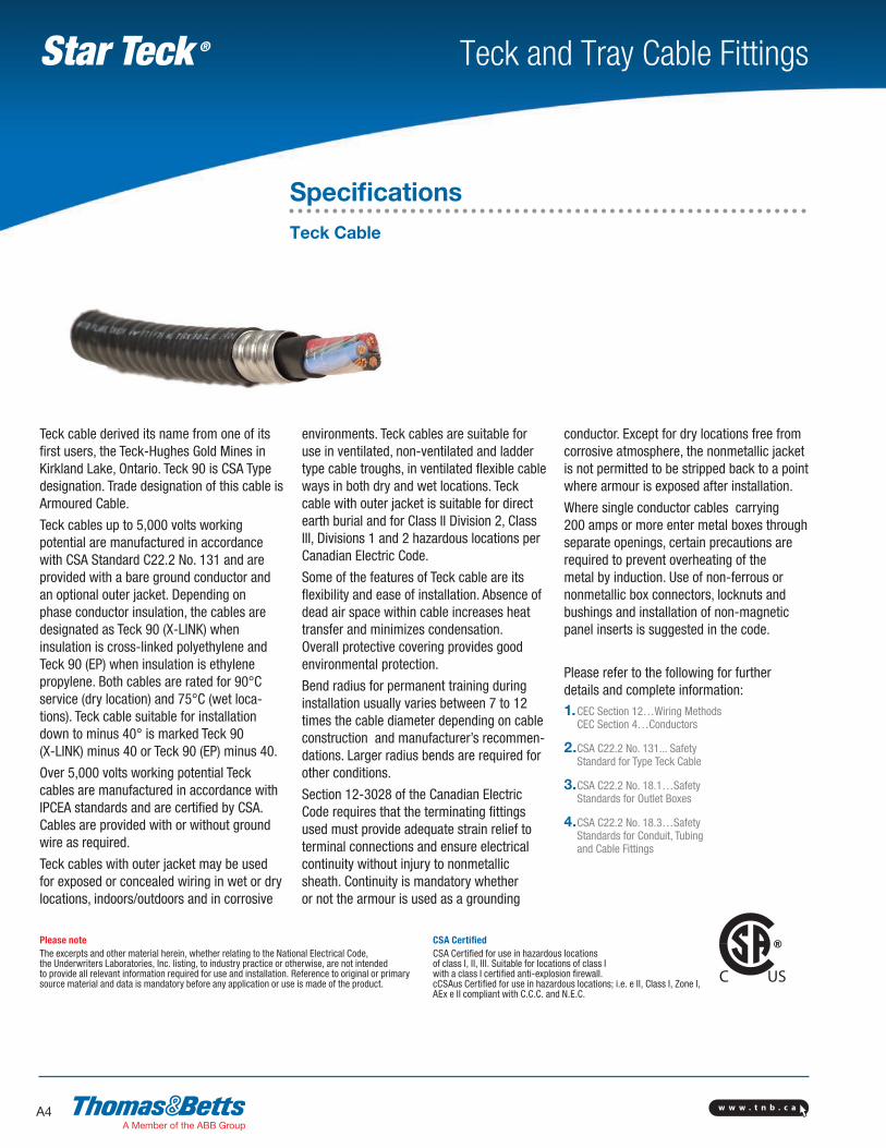
Teck cable derived its name from one of its first users, the Teck-Hughes Gold Mines in Kirkland Lake, Ontario. Teck 90 is CSA Type designation. Trade designation of this cable is Armoured Cable.
Teck cables up to 5,000 volts working potential are manufactured in accordance with CSA Standard C22.2 No. 131 and are provided with a bare ground conductor and an optional outer jacket. Depending on phase conductor insulation, the cables are designated as Teck 90 (X-LINK) when insulation is cross-linked polyethylene and Teck 90 (EP) when insulation is ethylene propylene. Both cables are rated for 90°C service (dry location) and 75°C (wet loca-tions). Teck cable suitable for installation down to minus 40° is marked Teck 90 (X-LINK) minus 40 or Teck 90 (EP) minus 40.
Over 5,000 volts working potential Teck cables are manufactured in accordance with IPCEA standards and are certified by CSA. Cables are provided with or without ground wire as required.
Teck cables with outer jacket may be used for exposed or concealed wiring in wet or dry locations, indoors/outdoors and in corrosive
environments. Teck cables are suitable for use in ventilated, non-ventilated and ladder type cable troughs, in ventilated flexible cable ways in both dry and wet locations. Teck cable with outer jacket is suitable for direct earth burial and for Class II Division 2, Class III, Divisions 1 and 2 hazardous locations per Canadian Electric Code.
Some of the features of Teck cable are its flexibility and ease of installation. Absence of dead air space within cable increases heat transfer and minimizes condensation. Overall protective cove ring provides good environmental protection.
Bend radius for permanent training during installation usually varies between 7 to 12 times the cable diameter depending on cable construction and manufacturer’s recommen-dations. Larger radius bends are required for other conditions.
Section 12-3028 of the Canadian Electric Code requires that the terminating fittings used must pro vide adequate strain relief to terminal connections and ensure electrical continuity without injury to nonmetallic sheath. Continuity is mandatory whether or not the armour is used as a grounding
conductor. Except for dry locations free from corrosive atmosphere, the nonmetallic jacket is not permitted to be stripped back to a point where armour is exposed after installation.
Where single conductor cables carrying 200 amps or more enter metal boxes through separate openings, certain precautions are required to prevent overheating of the metal by induction. Use of non-ferrous or nonmetallic box connectors, locknuts and bushings and installation of non-magnetic panel inserts is suggested in the code.
Please refer to the following for further details and complete information:1. CEC Section 12…Wiring Methods
CEC Section 4…Conductors
2. CSA C22.2 No. 131... Safety Standard for Type Teck Cable
3. CSA C22.2 No. 18.1…Safety Standards for Outlet Boxes
4. CSA C22.2 No. 18.3…Safety Standards for Conduit, Tubing and Cable Fittings
SpecificationsTeck Cable
w w w . t n b . c a A5
Teck and Tray Cable FittingsStar Teck ®
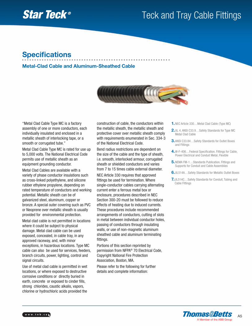
“Metal Clad Cable Type MC is a factory assembly of one or more conductors, each individually insulated and enclosed in a metallic sheath of interlocking tape, or a smooth or corrugated tube.”
Metal Clad Cable Type MC is rated for use up to 5,000 volts. The National Electrical Code permits use of metallic sheath as an equipment grounding conductor.
Metal Clad Cables are available with a variety of phase conductor insulations such as cross-linked polyethylene, and silicone rubber ethylene propylene, depending on rated temperature of conductors and working potential. Metallic sheath can be of galvanized steel, aluminum, copper or bronze. A special outer covering such as PVC or Neoprene over metallic sheath is usually provided for environmental protection.
Metal clad cable is not permitted in locations where it could be subject to physical damage. Metal clad cable can be used exposed, concealed, in cable tray, in any approved raceway, and, with minor exceptions, in hazardous locations. Type MC cable can also be used for services, feeders, branch circuits, power, lighting, control and signal circuits.
Use of metal clad cable is permitted in wet locations, or where exposed to destructive corrosive conditions or directly buried in earth, concrete or exposed to cinder fills, strong chlorides, caustic alkalis, vapors, chlorine or hydrochloric acids provided the
construction of cable, the conductors within the metallic sheath, the metallic sheath and protective cover over metallic sheath comply with requirements enumerated in Sec. 334-3 of the National Electrical Code.
Bend radius restrictions are dependent on the size of the cable and the type of sheath, i.e. smooth, interlocked armour, corrugated sheath or shielded conductors and varies from 7 to 15 times cable external diameter.
NEC Article 330 requires that approved fittings be used for termination. Where single-conductor cables carrying alternating current enter a ferrous metal box or enclosure, procedures described in NEC Section 300-20 must be followed to reduce effects of heating due to induced currents. These procedures include recommended arrangements of conductors, cutting of slots in metal between individual conductor holes, passing of conductors through insulating walls, or use of non-magnetic aluminum sheathed cable and aluminum terminating fittings.
Portions of this section reprinted by permission from NFPA® 70 Electrical Code, Copyright National Fire Protection Association, Boston, MA.
Please refer to the following for further details and complete information:
1. NEC Article 330…Metal Clad Cable (Type MC)
2. UL 4, ANSI C33.9…Safety Standards for Type MC Metal Clad Cable
3. ANSI C33.84…Safety Standards for Outlet Boxes and Fittings
4. W-F-406…Federal Specification. Fittings for Cable, Power Electrical and Conduit Metal, Flexible
5. NEMA FM-1…Standards Publication. Fittings and Supports for Conduit and Cable Assemblies
6. UL514A…Safety Standards for Metallic Outlet Boxes
7. UL514C…Safety Standards for Conduit, Tubing and Cable Fittings
SpecificationsMetal-Clad Cable and Aluminum-Sheathed Cable
w w w . t n b . c aA6
Teck and Tray Cable FittingsStar Teck ®
CEC Code Changes In 1998, the Canadian Electrical Code® (CEC) adopted the International Electrotechnical Commis-sion’s (IEC) “Three Zone Area” Classification System for Class I hazardous locations. The Zone System is an alternate classification for Class I hazardous lo-cations and was adopted to promote harmonization with international standards.
The Division System for Class I hazardous locations continues to be used for existing facilities and is expected to remain in use at least for the next few editions of the CEC. For this reason, this catalogue’s certification information for Class I hazardous loca-tions includes both the pre-1998 Division System and the new IEC Zone System.
The following pages provide an overview of CEC hazardous location classifications.
Classes The Canadian Electrical Code® (CEC), Part I, Section 18-Hazardous Locations, identifies three classes of hazardous locations:• Class I - Gas and Vapour Environments• Class II - Dust Environments• Class III - Fibers and Flyings Environments
The 1998 revisions to the CEC affect only Class I-Gas and Vapour Environments.
Hazardous location is defined by the CEC as premises, buildings or parts thereof in which there exists the hazard of fire or explosion due to highly flammable gases and/or flammable, volatile liquid mixtures that are manufactured, used or stored in other than the original containers.
This definition can also be extended to include combustible dust and easily ignitable fibers that are likely to be present in sufficient quantities to produce an explosive mixture.
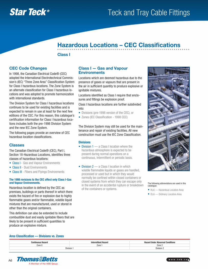
Class I — Gas and Vapour EnvironmentsLocations which are deemed hazardous due to the presence of gases or vapours that are present in the air in sufficient quantity to produce explosive or ignitable mixtures.
Locations identified as Class I require that enclo-sures and fittings be explosion proof.
Class I hazardous locations are further subdivided into:• Divisions (pre-1998 version of the CEC), or• Zones (IEC Classification - 1998 CEC)
The Division System may still be used for the main-tenance and repair of existing facilities. All new construction must use the IEC Zone Classification.
Divisions• Division 1 — a Class I location where the
hazardous atmosphere is expected to be present during normal operations on a continuous, intermittent or periodic basis.
• Division 2 — a Class I location in which volatile flammable liquids or gases are handled, processed or used but in which they would normally be confined within closed containers or closed systems from which they can escape only in the event of an accidental rupture or breakdown of the containers or systems.
The following abbreviations are used in this catalogue:
• HLA — Hazardous Location Area
• OLA — Ordinary Location Area
Area Classification — Divisions vs. Zones
Continuous Hazard Intermittent Hazard Hazard Under Abnormal ConditionsZone 0 Zone 1 Zone 2
Division 1 Division 2
Hazardous Locations – CEC ClassificationsClass I
w w w . t n b . c a A7
Teck and Tray Cable FittingsStar Teck ®
Zones• Zone 0 — Class I locations in which explosive
gas atmospheres are present continuously or are present for long periods.
• Zone 1 — Class I locations in which: i. explosive gas atmospheres are likely to occur in normal
operation; or
ii. explosive gas atmospheres may exist frequently because of repair or maintenance operations or because of leakage; or
iii. the location is adjacent to a Class I, Zone 0 location, from which explosive gas atmospheres could be communicated.
• Zone 2 — Class I locations in which: iv. explosive gas atmospheres are not likely to occur in
normal operation and if they do occur they will exist for a short time only; or
v. flammable volatile liquids, flammable gases or vapours are handled, processed, or used, but in which liquids, gases or vapours are normally
confined within closed containers or closed systems from which they can escape only as a result of accidental rupture or breakdown of the containers or systems or the abnormal operation of the equipment by which the liquids or gases are han-dled, processed or used; or
vi. explosive gas atmospheres are normally prevented by adequate ventilation but they may occur as a result of failure or abnormal operation of the ventilation system; or
vii. the location is adjacent to a Class I, Zone 1 location from which explosive gas atmospheres could be communicated, unless such communication is prevented by adequate positive-pressure ventilation from a source of clean air, and effective safe-guards against ventilation failure are provided.
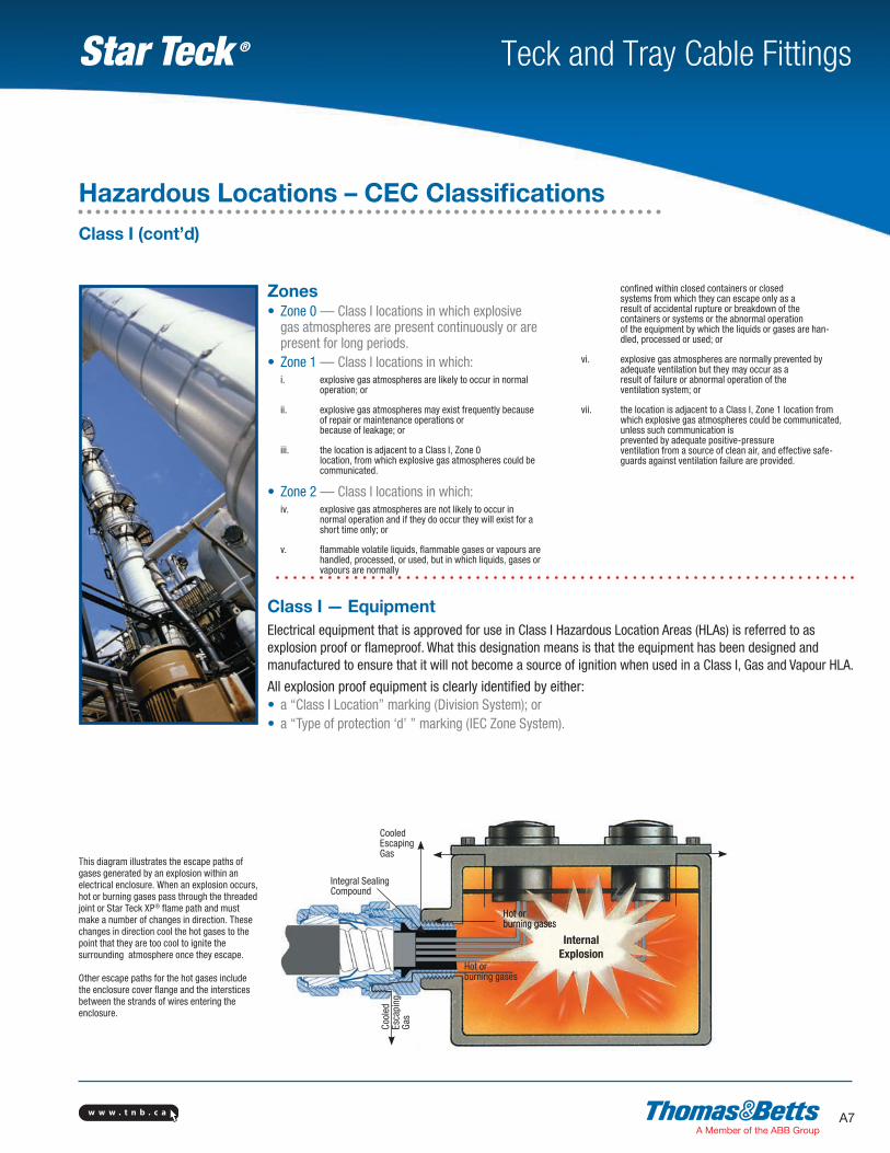
This diagram illustrates the escape paths of gases generated by an explosion within an electrical enclosure. When an explosion occurs, hot or burning gases pass through the threaded joint or Star Teck XP® flame path and must make a number of changes in direction. These changes in direction cool the hot gases to the point that they are too cool to ignite the surrounding atmosphere once they escape.
Other escape paths for the hot gases include the enclosure cover flange and the interstices between the strands of wires entering the enclosure.
Class I — EquipmentElectrical equipment that is approved for use in Class I Hazardous Location Areas (HLAs) is referred to as explosion proof or flameproof. What this designation means is that the equipment has been designed and manufactured to ensure that it will not become a source of ignition when used in a Class I, Gas and Vapour HLA.
All explosion proof equipment is clearly identified by either:• a “Class I Location” marking (Division System); or • a “Type of protection ‘d’ ” marking (IEC Zone System).
Hot or burning gases
Integral Sealing Compound
InternalExplosion
Cool
ed
Esca
ping
Ga
s
Hazardous Locations – CEC ClassificationsClass I (cont’d)
Cooled Escaping Gas
Hot or burning gases
w w w . t n b . c aA8
Teck and Tray Cable FittingsStar Teck ®
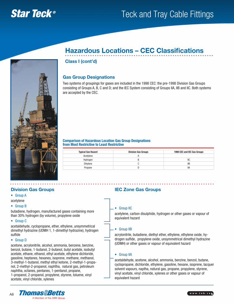
Gas Group DesignationsTwo systems of groupings for gases are included in the 1998 CEC: the pre-1998 Division Gas Groups consisting of Groups A, B, C and D; and the IEC System consisting of Groups IIA, IIB and IIC. Both systems are accepted by the CEC.
Division Gas Groups• Group Aacetylene• Group B butadiene, hydrogen, manufactured gases containing more than 30% hydrogen (by volume), propylene oxide• Group C acetaldehyde, cyclopropane, ether, ethylene, unsymmetrical dimethyl hydrazine (UDMH 1, 1-dimethyl hydrazine), hydrogen sulfide• Group D acetone, acrylonitrile, alcohol, ammonia, benzene, benzine, benzol, butane, 1-butanol, 2-butanol, butyl acetate, isobutyl acetate, ethane, ethanol, ethyl acetate, ethylene dichloride, gasoline, heptanes, hexanes, isoprene, methane, methanol, 3-methyl-1-butanol, methyl ethyl ketone, 2-methyl-1-propa-nol, 2-methyl-2-propanol, naphtha, natural gas, petroleum naphtha, octanes, pentanes, 1-pentanol, propane, 1-propanol, 2-propanol, propylene, styrene, toluene, vinyl acetate, vinyl chloride, xylenes
IEC Zone Gas Groups
• Group IIC
acetylene, carbon disulphide, hydrogen or other gases or vapour of equivalent hazard
• Group IIB
acrylonitrile, butadiene, diethyl ether, ethylene, ethylene oxide, hy-drogen sulfide, propylene oxide, unsymmetrical dimethyl hydrazine (UDMH) or other gases or vapour of equivalent hazard
• Group IIA
acetaldehyde, acetone, alcohol, ammonia, benzine, benzol, butane, cyclopropane, dichloride, ethylene, gasoline, hexane, isoprene, lacquer solvent vapours, naptha, natural gas, propane, propylene, styrene, vinyl acetate, vinyl chloride, xylenes or other gases or vapour of equivalent hazard
Comparison of Hazardous Location Gas Group Designations from Most Restrictive to Least Restrictive
Typical Gas Hazard Division Gas Groups 1998 CEC and IEC Gas GroupsAcetylene A
Hydrogen B IIC
Ethylene C IIB
Propane D IIA
Hazardous Locations – CEC ClassificationsClass I (cont’d)
w w w . t n b . c a A9
Teck and Tray Cable FittingsStar Teck ®
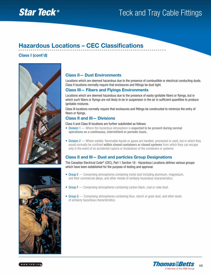
Class II— Dust EnvironmentsLocations which are deemed hazardous due to the presence of combustible or electrical conducting dusts. Class II locations normally require that enclosures and fittings be dust tight.
Class III— Fibers and Flyings EnvironmentsLocations which are deemed hazardous due to the presence of easily ignitable fibers or flyings, but in which such fibers or flyings are not likely to be in suspension in the air in sufficient quantities to produce ignitable mixtures.
Class III locations normally require that enclosures and fittings be constructed to minimize the entry of fibers or flyings.
Class II and III— DivisionsClass II and Class III locations are further subdivided as follows:• Division 1 — Where the hazardous atmosphere is expected to be present during normal
operations on a continuous, intermittent or periodic basis.
• Division 2 — Where volatile, flammable liquids or gases are handled, processed or used, but in which they would normally be confined within closed containers or closed systems from which they can escape only in the event of an accidental rupture or breakdown of the containers or systems.
Class II and III— Dust and particles Group DesignationsThe Canadian Electrical Code® (CEC), Part 1 Section 18 - Hazardous Locations defines various groups which have been established for the purpose of testing and approval.
• Group E — Comprising atmospheres containing metal dust including aluminum, magnesium, and their commercial alloys, and other metals of similarly hazardous characteristics.
• Group F — Comprising atmospheres containing carbon black, coal or coke dust.
• Group G — Comprising atmospheres containing flour, starch or grain dust, and other dusts of similarly hazardous characteristics.
Hazardous Locations – CEC ClassificationsClass I (cont’d)
w w w . t n b . c aA10
Teck and Tray Cable FittingsStar Teck ®
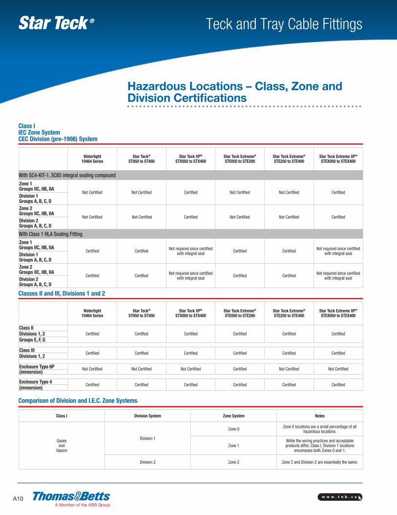
Class I IEC Zone System CEC Division (pre-1998) System
Classes II and III, Divisions 1 and 2
Watertight 10464 Series
Star Teck® ST050 to ST400
Star Teck XP® STX050 to STX400
Star Teck Extreme® STE050 to STE200
Star Teck Extreme® STE250 to STE400
Star Teck Extreme XP® STEX050 to STEX400
With SC4-KIT-1, SC65 integral sealing compoundZone 1 Groups IIC, IIB, IIA
Not Certified Not Certified Certified Not Certified Not Certified CertifiedDivision 1 Groups A, B, C, DZone 2 Groups IIC, IIB, IIA
Not Certified Not Certified Certified Not Certified Not Certified CertifiedDivision 2 Groups A, B, C, D
With Class 1 HLA Sealing FittingZone 1 Groups IIC, IIB, IIA
Certified Certified Not required since certified with integral seal Certified Certified Not required since certified
with integral sealDivision 1 Groups A, B, C, DZone 2 Groups IIC, IIB, IIA
Certified Certified Not required since certified with integral seal Certified Certified Not required since certified
with integral sealDivision 2 Groups A, B, C, D
Watertight 10464 Series
Star Teck® ST050 to ST400
Star Teck XP® STX050 to STX400
Star Teck Extreme® STE050 to STE200
Star Teck Extreme® STE250 to STE400
Star Teck Extreme XP® STEX050 to STEX400
Class IICertified Certified Certified Certified Certified CertifiedDivisions 1, 2
Groups E, F, G
Class IIICertified Certified Certified Certified Certified Certified
Divisions 1, 2
Enclosure Type 6P Not Certified Not Certified Not Certified Certified Not Certified Not Certified(immersion)
Enclosure Type 4Certified Certified Certified Certified Certified Certified
(immersion)
Comparison of Division and I.E.C. Zone Systems
Class I Division System Zone System Notes
Gases and
Vapors
Division 1
Zone 0 Zone 0 locations are a small percentage of all hazardous locations.
Zone 1While the wiring practices and acceptable products differ, Class I, Division 1 locations
encompass both Zones 0 and 1.
Division 2 Zone 2 Zone 2 and Division 2 are essentially the same.
Hazardous Locations – Class, Zone and Division Certifications
w w w . t n b . c a A11
Teck and Tray Cable FittingsStar Teck ®
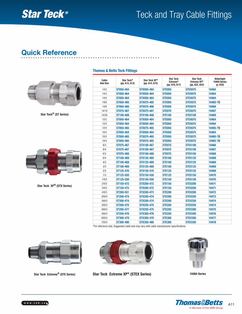
Star Teck® (ST Series)
Thomas & Betts Teck Fittings
CableHub Size
Star Teck® (pp. A12, A13)
Star Teck XP® (pp. A14, A15)
Star TeckExtreme®
(pp. A16, A17)
Star Teck Extreme XP® (pp. A22, A23)
Watertight10464 Series
(p. A24)
14/2 ST050-464 STX050-464 STE050 STEX075 1046414/3 ST050-464 STX050-464 STE050 STEX075 1046414/4 ST050-464 STX050-464 STE050 STEX075 1046414/6 ST050-465 STX075-465 STE050 STEX075 10465-TB14/8 ST050-466 STX075-466 STE050 STEX075 1046614/10 ST075-467 STX075-467 STE075 STEX075 1046714/20 ST100-469 STX100-468 STE100 STEX100 1046912/2 ST050-464 STX050-464 STE050 STEX075 1046412/3 ST050-464 STX050-464 STE050 STEX075 1046412/4 ST050-465 STX075-465 STE050 STEX075 10465-TB10/2 ST050-464 STX050-464 STE050 STEX075 1046410/3 ST050-465 STX075-465 STE050 STEX075 10465-TB10/4 ST050-465 STX075-465 STE050 STEX075 10465-TB8/3 ST075-467 STX100-467 STE075 STEX100 104668/4 ST075-467 STX100-467 STE075 STEX100 104676/3 ST075-468 STX100-468 STE075 STEX100 104686/4 ST100-469 STX125-469 STE100 STEX125 104684/3 ST100-469 STX125-469 STE100 STEX125 104693/3 ST100-469 STX125-469 STE100 STEX125 104692/3 ST125-470 STX150-470 STE125 STEX125 104691/3 ST125-550 STX150-550 STE125 STEX150 10470
1/0/3 ST125-550 STX150-550 STE150 STEX150 104702/0/3 ST150-472 STX200-472 STE150 STEX200 104713/0/3 ST150-472 STX200-472 STE150 STEX200 104714/0/3 ST200-551 STX200-473 STE200 STEX200 10472250/3 ST200-474 STX200-474 STE200 STEX250 10473300/3 ST200-474 STX200-474 STE200 STEX250 10474350/3 ST200-475 STX250-475 STE200 STEX250 10474400/3 ST250-477 STX250-475 STE250 STEX300 10475500/3 ST250-478 STX300-478 STE250 STEX300 10476600/3 ST300-479 STX300-479 STE300 STEX300 10477750/3 ST300-480 STX350-480 STE300 STEX350 10478
*For reference only. Suggested cable size may vary with cable manufacturer specifications
Star Teck XP® (STX Series)
Star Teck Extreme® (STE Series) Star Teck Extreme XP® (STEX Series) 10464 Series
Quick Reference
w w w . t n b . c aA12
Teck and Tray Cable FittingsStar Teck ®
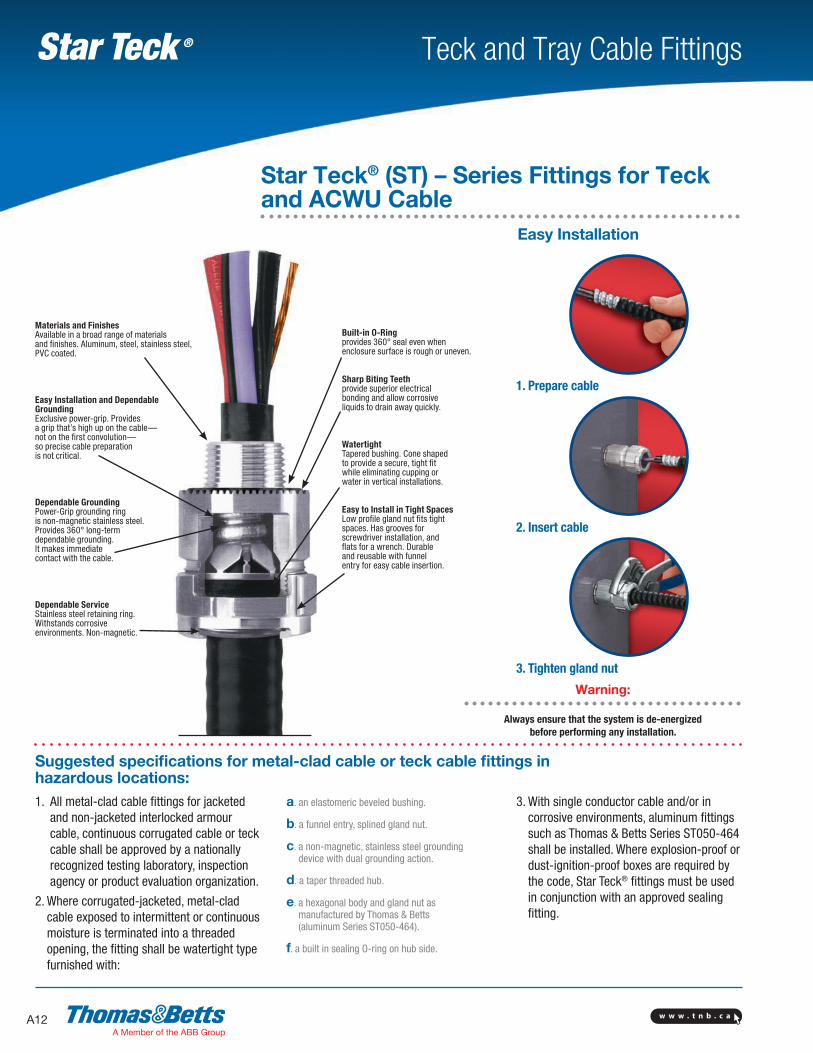
Warning: Always ensure that the system is de-energized
before performing any installation.
Built-in O-Ringprovides 360° seal even when enclosure surface is rough or uneven.
Sharp Biting Teethprovide superior electrical bonding and allow corrosive liquids to drain away quickly.
WatertightTapered bushing. Cone shaped to provide a secure, tight fit while eliminating cupping or water in vertical installations.
Easy to Install in Tight SpacesLow profile gland nut fits tight spaces. Has grooves for screwdriver installation, and flats for a wrench. Durable and reusable with funnel entry for easy cable insertion.
Materials and FinishesAvailable in a broad range of materials and finishes. Aluminum, steel, stainless steel, PVC coated.
Easy Installation and Dependable GroundingExclusive power-grip. Provides a grip that’s high up on the cable— not on the first convolution— so precise cable preparation is not critical.
Dependable GroundingPower-Grip grounding ring is non-magnetic stainless steel. Provides 360° long-term dependable grounding. It makes immediate contact with the cable.
Dependable ServiceStainless steel retaining ring. Withstands corrosive environments. Non-magnetic.
1. All metal-clad cable fittings for jacketed and non-jacketed interlocked armour cable, continuous corrugated cable or teck cable shall be approved by a nationally recognized testing laboratory, inspection agency or product evaluation organization.
2. Where corrugated-jacketed, metal-clad cable exposed to intermittent or continuous moisture is terminated into a threaded opening, the fitting shall be watertight type furnished with:
a. an elastomeric beveled bushing.
b. a funnel entry, splined gland nut.
c. a non-magnetic, stainless steel grounding device with dual grounding action.
d. a taper threaded hub.
e. a hexagonal body and gland nut as manufactured by Thomas & Betts (aluminum Series ST050-464).
f. a built in sealing O-ring on hub side.
3. With single conductor cable and/or in corrosive environments, aluminum fittings such as Thomas & Betts Series ST050-464 shall be installed. Where explosion-proof or dust-ignition-proof boxes are required by the code, Star Teck® fittings must be used in conjunction with an approved sealing fitting.
Suggested specifications for metal-clad cable or teck cable fittings in hazardous locations:
1. Prepare cable
2. Insert cable
3. Tighten gland nut
Star Teck® (ST) – Series Fittings for Teck and ACWU Cable
Easy Installation
w w w . t n b . c a A13
Teck and Tray Cable FittingsStar Teck ®
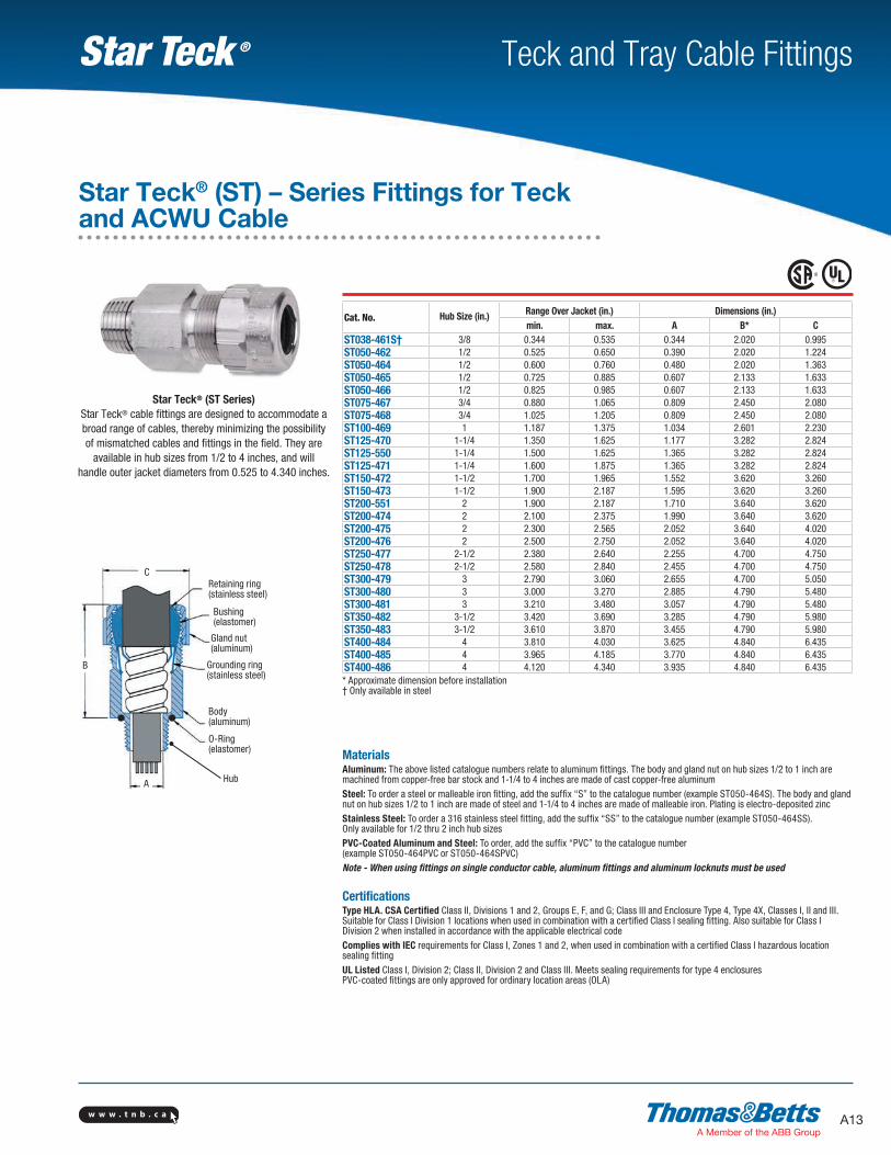
MaterialsAluminum: The above listed catalogue numbers relate to aluminum fittings. The body and gland nut on hub sizes 1/2 to 1 inch are machined from copper-free bar stock and 1-1/4 to 4 inches are made of cast copper-free aluminumSteel: To order a steel or malleable iron fitting, add the suffix “S” to the catalogue number (example ST050-464S). The body and gland nut on hub sizes 1/2 to 1 inch are made of steel and 1-1/4 to 4 inches are made of malleable iron. Plating is electro-deposited zincStainless Steel: To order a 316 stainless steel fitting, add the suffix “SS” to the catalogue number (example ST050-464SS). Only available for 1/2 thru 2 inch hub sizesPVC-Coated Aluminum and Steel: To order, add the suffix “PVC” to the catalogue number (example ST050-464PVC or ST050-464SPVC)Note - When using fittings on single conductor cable, aluminum fittings and aluminum locknuts must be used
CertificationsType HLA. CSA Certified Class II, Divisions 1 and 2, Groups E, F, and G; Class III and Enclosure Type 4, Type 4X, Classes I, II and III. Suitable for Class I Division 1 locations when used in combination with a certified Class I sealing fitting. Also suitable for Class I Division 2 when installed in accordance with the applicable electrical codeComplies with IEC requirements for Class I, Zones 1 and 2, when used in combination with a certified Class I hazardous location sealing fittingUL Listed Class I, Division 2; Class II, Division 2 and Class III. Meets sealing requirements for type 4 enclosures PVC-coated fittings are only approved for ordinary location areas (OLA)
Cat. No. Hub Size (in.) Range Over Jacket (in.) Dimensions (in.)min. max. A B* C
ST038-461S† 3/8 0.344 0.535 0.344 2.020 0.995ST050-462 1/2 0.525 0.650 0.390 2.020 1.224ST050-464 1/2 0.600 0.760 0.480 2.020 1.363ST050-465 1/2 0.725 0.885 0.607 2.133 1.633ST050-466 1/2 0.825 0.985 0.607 2.133 1.633ST075-467 3/4 0.880 1.065 0.809 2.450 2.080ST075-468 3/4 1.025 1.205 0.809 2.450 2.080ST100-469 1 1.187 1.375 1.034 2.601 2.230ST125-470 1-1/4 1.350 1.625 1.177 3.282 2.824ST125-550 1-1/4 1.500 1.625 1.365 3.282 2.824ST125-471 1-1/4 1.600 1.875 1.365 3.282 2.824ST150-472 1-1/2 1.700 1.965 1.552 3.620 3.260ST150-473 1-1/2 1.900 2.187 1.595 3.620 3.260ST200-551 2 1.900 2.187 1.710 3.640 3.620ST200-474 2 2.100 2.375 1.990 3.640 3.620ST200-475 2 2.300 2.565 2.052 3.640 4.020ST200-476 2 2.500 2.750 2.052 3.640 4.020ST250-477 2-1/2 2.380 2.640 2.255 4.700 4.750ST250-478 2-1/2 2.580 2.840 2.455 4.700 4.750ST300-479 3 2.790 3.060 2.655 4.700 5.050ST300-480 3 3.000 3.270 2.885 4.790 5.480ST300-481 3 3.210 3.480 3.057 4.790 5.480ST350-482 3-1/2 3.420 3.690 3.285 4.790 5.980ST350-483 3-1/2 3.610 3.870 3.455 4.790 5.980ST400-484 4 3.810 4.030 3.625 4.840 6.435ST400-485 4 3.965 4.185 3.770 4.840 6.435ST400-486 4 4.120 4.340 3.935 4.840 6.435* Approximate dimension before installation† Only available in steel
B
C
A
Retaining ring (stainless steel)
Bushing (elastomer)
Gland nut (aluminum)
Grounding ring (stainless steel)
Body (aluminum)
O-Ring (elastomer)
Hub
Star Teck® (ST Series)Star Teck® cable fittings are designed to accommodate a broad range of cables, thereby minimizing the possibility of mismatched cables and fittings in the field. They are
available in hub sizes from 1/2 to 4 inches, and will handle outer jacket diameters from 0.525 to 4.340 inches.
Star Teck® (ST) – Series Fittings for Teck and ACWU Cable
w w w . t n b . c aA14
Teck and Tray Cable FittingsStar Teck ®
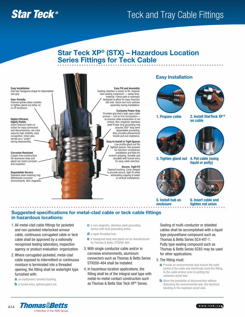
Easy InstallationHub has hexagonal shape for dependable tool grip.
User-friendlyInternal splines allow installer to tighten gland nut either on or off enclosure.
Highly Efficient, Highly VisibleUnion features twist-on action for easy connection and disconnection; red color assures high visibility, easy recognition. Union also serves as a “puller” during disassembly.
Corrosion ResistantCopper-free construction. All-aluminum body and gland nut resist corrosion and oxydation.
Dependable ServiceStainless steel retaining ring. Withstands corrosive environments. Non-magnetic.
Easy Fill and AssemblySealing chamber is easier to fill, requires
less sealing compound — saves time, material. Flame path is optimally
designed to allow for easy insertion into hub. Quick-turn lock unitizes
assembly during installation.
Exclusive Power GripProvides grip that’s high upon cable armour— not on first convolution—
so precise cable preparation is not critical. Non-magnetic stainless steel Power Grip grounding ring
assures 360° long-term dependable grounding.
Also provides phenomenal tensile pull out resistance.
Easy to Install in Tight SpacesLow profile gland nut fits
tightest spaces. Has grooves for hammer/ screwdriver installation and flats for
wrench-gripping. Durable and reusable with funnel entry
for easy cable insertion.
Secure, Tight FitTapered bushing. Cone-shaped to provide secure, tight fit while
eliminating cupping of water in vertical installations.
1. All metal-clad cable fittings for jacketed and non-jacketed interlocked armour cable, continuous corrugated cable or teck cable shall be approved by a nationally recognized testing laboratory, inspection agency or product evaluation organization.
2. Where corrugated-jacketed, metal-clad cable exposed to intermittent or continuous moisture is terminated into a threaded opening, the fitting shall be watertight type furnished with:
a. an elastomeric beveled bushing.
b. a funnel entry, splined gland nut.
c. a non-magnetic, stainless steel grounding device with dual grounding action.
d. a taper threaded hub.
e. a hexagonal body and gland nut as manufactured by Thomas & Betts, STX050-464.
3. With single conductor cable and/or in corrosive environments, aluminum connectors such as Thomas & Betts Series STX050-464 shall be installed.
4. In hazardous location applications, the fitting shall be of the integral seal type with metal-to-metal contact construction such as Thomas & Betts Star Teck XP® Series.
Sealing of multi-conductor or shielded cables shall be accomplished with a liquid type polyurethane compound such as Thomas & Betts Series SC4-KIT-1. Putty type sealing compound such as Thomas & Betts Series SC65 may be used for other applications.
5. The fitting must: a. Provide an environmental seal around the outer
jacket of the cable and electrically bond the fitting to the cable armour prior to potting the explosion-proof seal.
b. Allow the possibility of disconnection without disturbing the environmental seal, the electrical bonding or the explosion-proof seal.
Suggested specifications for metal-clad cable or teck cable fittings in hazardous locations:
Easy Installation
1. Prepare cable 2. Install StarTeck XP ® on cable
3. Tighten gland nut 4. Pot cable (using liquid or putty)
5. Install hub on enclosure
6. Insert cable and tighten red union
Star Teck XP® (STX) – Hazardous Location Series Fittings for Teck Cable
w w w . t n b . c a A15
Teck and Tray Cable FittingsStar Teck ®
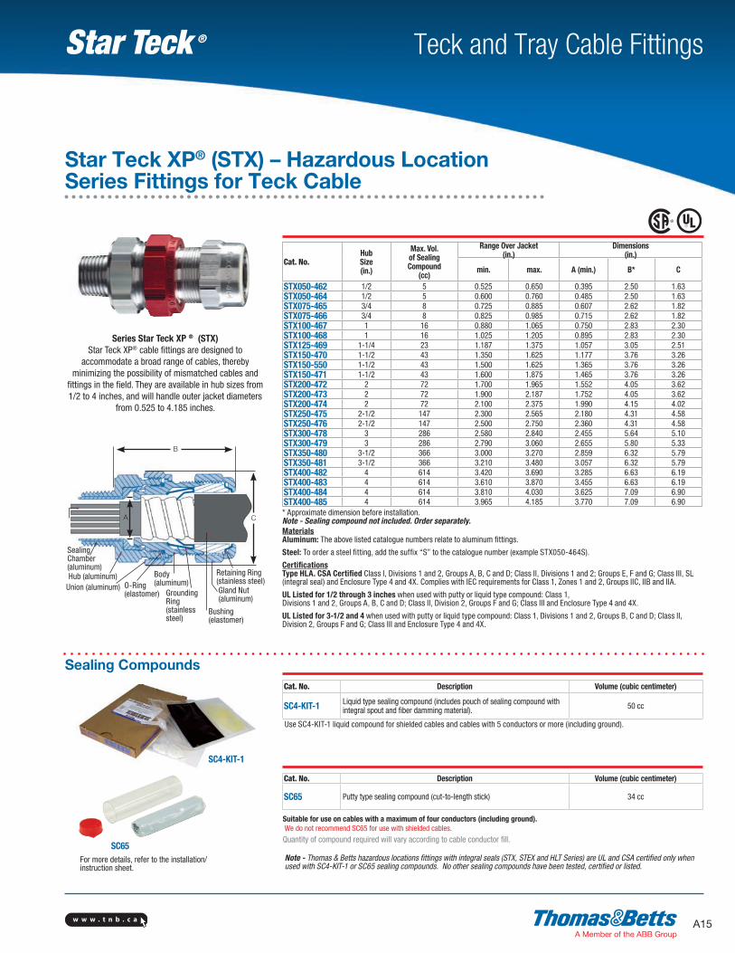
Hub (aluminum)Union (aluminum)
Body (aluminum)
Gland Nut (aluminum)
Bushing (elastomer)
Retaining Ring (stainless steel)
CA
B
Grounding Ring(stainless steel)
Sealing Chamber(aluminum)
O-Ring (elastomer)
Ø
Ø
Ø
Ø Ø
ØØ
Ø
Ø
Note - Thomas & Betts hazardous locations fittings with integral seals (STX, STEX and HLT Series) are UL and CSA certified only when used with SC4-KIT-1 or SC65 sealing compounds. No other sealing compounds have been tested, certified or listed.
SC65
Cat. No.Hub Size (in.)
Max. Vol. of Sealing Compound
(cc)
Range Over Jacket (in.)
Dimensions (in.)
min. max. A (min.) B* C
STX050-462 1/2 5 0.525 0.650 0.395 2.50 1.63STX050-464 1/2 5 0.600 0.760 0.485 2.50 1.63STX075-465 3/4 8 0.725 0.885 0.607 2.62 1.82STX075-466 3/4 8 0.825 0.985 0.715 2.62 1.82STX100-467 1 16 0.880 1.065 0.750 2.83 2.30STX100-468 1 16 1.025 1.205 0.895 2.83 2.30STX125-469 1-1/4 23 1.187 1.375 1.057 3.05 2.51STX150-470 1-1/2 43 1.350 1.625 1.177 3.76 3.26STX150-550 1-1/2 43 1.500 1.625 1.365 3.76 3.26STX150-471 1-1/2 43 1.600 1.875 1.465 3.76 3.26STX200-472 2 72 1.700 1.965 1.552 4.05 3.62STX200-473 2 72 1.900 2.187 1.752 4.05 3.62STX200-474 2 72 2.100 2.375 1.990 4.15 4.02STX250-475 2-1/2 147 2.300 2.565 2.180 4.31 4.58STX250-476 2-1/2 147 2.500 2.750 2.360 4.31 4.58STX300-478 3 286 2.580 2.840 2.455 5.64 5.10STX300-479 3 286 2.790 3.060 2.655 5.80 5.33STX350-480 3-1/2 366 3.000 3.270 2.859 6.32 5.79STX350-481 3-1/2 366 3.210 3.480 3.057 6.32 5.79STX400-482 4 614 3.420 3.690 3.285 6.63 6.19STX400-483 4 614 3.610 3.870 3.455 6.63 6.19STX400-484 4 614 3.810 4.030 3.625 7.09 6.90STX400-485 4 614 3.965 4.185 3.770 7.09 6.90* Approximate dimension before installation.Note - Sealing compound not included. Order separately.Materials Aluminum: The above listed catalogue numbers relate to aluminum fittings.
Steel: To order a steel fitting, add the suffix “S” to the catalogue number (example STX050-464S).
Certifications Type HLA. CSA Certified Class I, Divisions 1 and 2, Groups A, B, C and D; Class II, Divisions 1 and 2; Groups E, F and G; Class III, SL (integral seal) and Enclosure Type 4 and 4X. Complies with IEC requirements for Class 1, Zones 1 and 2, Groups IIC, IIB and IIA.
UL Listed for 1/2 through 3 inches when used with putty or liquid type compound: Class 1, Divisions 1 and 2, Groups A, B, C and D; Class II, Division 2, Groups F and G; Class III and Enclosure Type 4 and 4X.
UL Listed for 3-1/2 and 4 when used with putty or liquid type compound: Class 1, Divisions 1 and 2, Groups B, C and D; Class II, Division 2, Groups F and G; Class III and Enclosure Type 4 and 4X.
Cat. No. Description Volume (cubic centimeter)
SC65 Putty type sealing compound (cut-to-length stick) 34 cc
Suitable for use on cables with a maximum of four conductors (including ground). We do not recommend SC65 for use with shielded cables.
Quantity of compound required will vary according to cable conductor fill.
Cat. No. Description Volume (cubic centimeter)
SC4-KIT-1 Liquid type sealing compound (includes pouch of sealing compound with integral spout and fiber damming material). 50 cc
Use SC4-KIT-1 liquid compound for shielded cables and cables with 5 conductors or more (including ground).
Sealing Compounds
For more details, refer to the installation/ instruction sheet.
Series Star Teck XP ® (STX)Star Teck XP® cable fittings are designed to
accommodate a broad range of cables, thereby minimizing the possibility of mismatched cables and
fittings in the field. They are available in hub sizes from 1/2 to 4 inches, and will handle outer jacket diameters
from 0.525 to 4.185 inches.
SC4-KIT-1
Star Teck XP® (STX) – Hazardous Location Series Fittings for Teck Cable
Ø
w w w . t n b . c aA16
Teck and Tray Cable FittingsStar Teck ®
1. All metal-clad cable fittings for jacketed and non-jacketed interlocked armour cable, continuous corrugated cable or teck cable shall be approved by a nationally recognized testing laboratory, inspection agency or product evaluation organization.
2. Where corrugated-jacketed, metal-clad cable exposed to intermittent or continuous moisture is terminated into a threaded opening, the fitting shall be watertight type furnished with:
a. an elastomeric beveled bushing. b. a funnel entry, splined gland nut. c. a non-magnetic, stainless steel grounding
device with dual grounding action. d. a taper threaded hub. e. a hexagonal body and gland nut as
manufactured by Thomas & Betts (aluminum Series STE050).
3. A synthetic rubber sealing device shall be captivated in a shoulder groove providing optimized sealing even on irregular surfaces. The configuration shall also prevent over-compression of the seal such as Thomas & Betts Series STE050, by incorporating a shoulder groove.
4. With single conductor cable and/or in corrosive environments, aluminum fittings such as Thomas & Betts Series STE050 shall be installed.
5. All metal-clad cable fittings, for jacketed and non-jacketed interlocked armour cable, shall provide external bonding/ground-ing teeth capable of penetrating surface finishes to contact enclosure base metal. (Thomas & Betts Series STE050.)
Suggested specifications for metal-clad cable or teck cable fittings in hazardous locations:
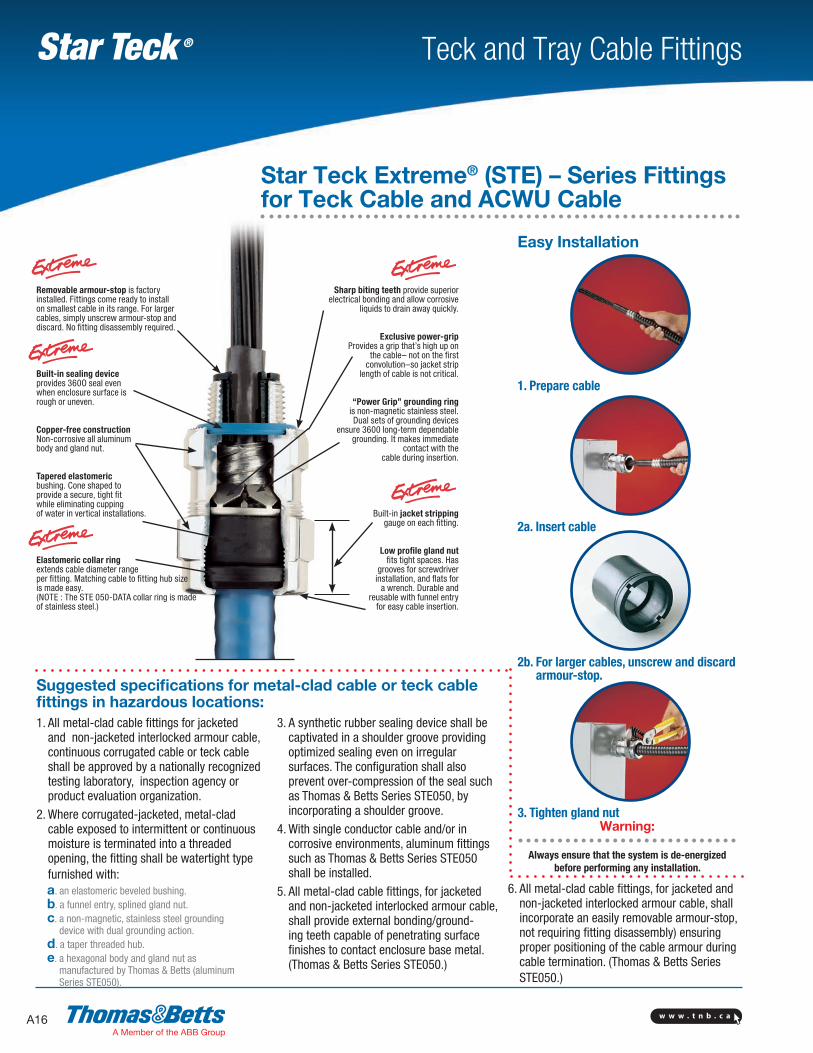
Sharp biting teeth provide superior electrical bonding and allow corrosive
liquids to drain away quickly.
Exclusive power-gripProvides a grip that’s high up on
the cable– not on the first convolution–so jacket strip
length of cable is not critical.
“Power Grip” grounding ring is non-magnetic stainless steel. Dual sets of grounding devices
ensure 3600 long-term dependable grounding. It makes immediate
contact with the cable during insertion.
Built-in jacket stripping gauge on each fitting.
Low profile gland nut fits tight spaces. Has
grooves for screwdriver installation, and flats for
a wrench. Durable and reusable with funnel entry
for easy cable insertion.
Removable armour-stop is factory installed. Fittings come ready to install on smallest cable in its range. For larger cables, simply unscrew armour-stop and discard. No fitting disassembly required.
Built-in sealing device provides 360O seal even when enclosure surface is rough or uneven.
Copper-free constructionNon-corrosive all aluminum body and gland nut.
Tapered elastomeric bushing. Cone shaped to provide a secure, tight fit while elimin ating cupping of water in vertical installations.
Elastomeric collar ring extends cable diameter range per fitting. Matching cable to fitting hub size is made easy.(NOTE : The STE 050-DATA collar ring is made of stainless steel.)
Easy Installation
1. Prepare cable
2a. Insert cable
2b. For larger cables, unscrew and discard armour-stop.
3. Tighten gland nut
Star Teck Extreme® (STE) – Series Fittings for Teck Cable and ACWU Cable
6. All metal-clad cable fittings, for jacketed and non-jacketed interlocked armour cable, shall incorporate an easily removable armour-stop, not requiring fitting disassembly) ensuring proper positioning of the cable armour during cable termination. (Thomas & Betts Series STE050.)
Warning: Always ensure that the system is de-energized
before performing any installation.
w w w . t n b . c a A17
Teck and Tray Cable FittingsStar Teck ®
Broadest range of teck cable diameters per hub size Star Teck Extreme® Cat. No.
Star Teck® Cat. No.
Hub Size (NPT) (in.)
Range over Jacket (in.) Min. - Max.
Eleven catalogue numbers cover the range from 0.500 to 4.340 inches. v ST038-461S 3/8 0.344 - 0.535STE050-DATA - 1/2 0.500 - 0.700
STE0500.600 - 0.985
ST050-462
1/2
0.525 - 0.650ST050-464 0.526 - 0.760ST050-465 0.725 - 0.885ST050-466 0.825 - 0.985
STE0750.860 - 1.205
ST075-467 3/40.880 - 1.065
ST075-468 1.250 - 1.205STE1000.950 - 1.375 ST100-469 1 1.187 - 1.375
STE1251.150 - 1.625
ST125-4701-1/4
1.350 - 1.625ST125-550 1.500 - 1.625ST125-471 1.600 - 1.875
STE1501.440 - 1.965
ST150-472 1-1/21.700 - 1.965
ST150-473 1.900 - 2.187
STE2001.825 - 2.375
ST200-551
2
1.900 - 2.187ST200-474 2.100 - 2.375ST200-475 2.300 - 2.565ST200-476 2.500 - 2.750
STE2502.265 - 2.840
ST250-477 2-1/22.380 - 2.640
ST250-478 2.580 - 2.840
STE3002.670 - 3.270
ST300-4793
2.790 - 3.060ST300-480 3.000 - 3.270ST300-481 3.210 - 3.480
STE3503.220 - 3.870
ST350-482 3-1/23.420 - 3.690
ST350-483 3.610 - 3.870
STE4003.665 - 4.340
ST400-4844
3.810 - 4.030ST400-485 3.965 - 4.185ST400-486 4.120 - 4.340
Cat. No.Hub Size (in.)
StripLenght
(in.)
GlandTorque(lb-in.)
Range OverJacket (in.)
Range OverArmour (in.)
A1Throat Dia.Min. (in.)
w/ ArmourStop
A2Throat Dia. Min. (in.)
w/o Armour Stop
B* Overall
(in.)
CMax.O.D.(in.)
Min. Max. Min. Max.
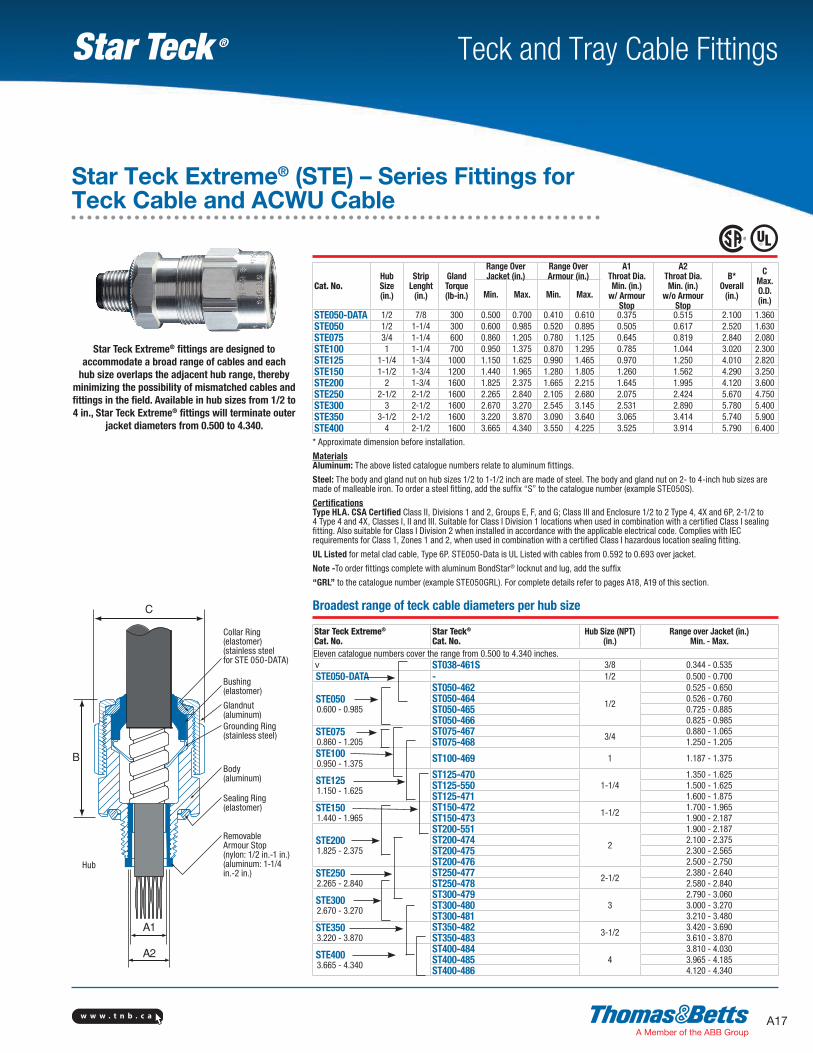
STE050-DATA 1/2 7/8 300 0.500 0.700 0.410 0.610 0.375 0.515 2.100 1.360STE050 1/2 1-1/4 300 0.600 0.985 0.520 0.895 0.505 0.617 2.520 1.630STE075 3/4 1-1/4 600 0.860 1.205 0.780 1.125 0.645 0.819 2.840 2.080STE100 1 1-1/4 700 0.950 1.375 0.870 1.295 0.785 1.044 3.020 2.300STE125 1-1/4 1-3/4 1000 1.150 1.625 0.990 1.465 0.970 1.250 4.010 2.820STE150 1-1/2 1-3/4 1200 1.440 1.965 1.280 1.805 1.260 1.562 4.290 3.250STE200 2 1-3/4 1600 1.825 2.375 1.665 2.215 1.645 1.995 4.120 3.600STE250 2-1/2 2-1/2 1600 2.265 2.840 2.105 2.680 2.075 2.424 5.670 4.750STE300 3 2-1/2 1600 2.670 3.270 2.545 3.145 2.531 2.890 5.780 5.400STE350 3-1/2 2-1/2 1600 3.220 3.870 3.090 3.640 3.065 3.414 5.740 5.900STE400 4 2-1/2 1600 3.665 4.340 3.550 4.225 3.525 3.914 5.790 6.400
* Approximate dimension before installation.
Materials Aluminum: The above listed catalogue numbers relate to aluminum fittings.
Steel: The body and gland nut on hub sizes 1/2 to 1-1/2 inch are made of steel. The body and gland nut on 2- to 4-inch hub sizes are made of malleable iron. To order a steel fitting, add the suffix “S” to the catalogue number (example STE050S).
Certifications Type HLA. CSA Certified Class II, Divisions 1 and 2, Groups E, F, and G; Class III and Enclosure 1/2 to 2 Type 4, 4X and 6P, 2-1/2 to 4 Type 4 and 4X, Classes I, II and III. Suitable for Class I Division 1 locations when used in combination with a certified Class I sealing fitting. Also suitable for Class I Division 2 when installed in accordance with the applicable electrical code. Complies with IEC requirements for Class 1, Zones 1 and 2, when used in combination with a certified Class I hazardous location sealing fitting.
UL Listed for metal clad cable, Type 6P. STE050-Data is UL Listed with cables from 0.592 to 0.693 over jacket.
Note -To order fittings complete with aluminum BondStar® locknut and lug, add the suffix
“GRL” to the catalogue number (example STE050GRL). For complete details refer to pages A18, A19 of this section.
Collar Ring (elastomer) (stainless steel for STE 050-DATA)
Bushing (elastomer)
Glandnut (aluminum) Grounding Ring(stainless steel)
Body (aluminum)
Sealing Ring (elastomer)
Removable Armour Stop (nylon: 1/2 in.-1 in.) (aluminum: 1-1/4 in.-2 in.)
Hub
Star Teck Extreme® fittings are designed to accommodate a broad range of cables and each
hub size overlaps the adjacent hub range, thereby minimizing the possibility of mismatched cables and fittings in the field. Available in hub sizes from 1/2 to 4 in., Star Teck Extreme® fittings will terminate outer
jacket diameters from 0.500 to 4.340.
Star Teck Extreme® (STE) – Series Fittings for Teck Cable and ACWU Cable
w w w . t n b . c aA18
Teck and Tray Cable FittingsStar Teck ®
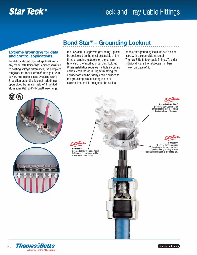
Extreme grounding for data and control applications.For data and control panel applications or any other installation that is highly sensitive to floating voltage differences, the complete range of Star Teck Extreme® fittings (1/2 in. to 4 in. hub sizes) is also available with a 3-position grounding locknut including an open-sided lay-in lug made of tin-plated aluminum. With a #4-14 AWG wire range,
the CSA and UL approved grounding lug can be positioned on the most accessible of the three grounding locations on the circum-ference of the installed grounding locknut. When installation requires multiple incoming cables, each individual lug terminating the connections can be “daisy chain” bonded to the grounding bus, ensuring the same electrical potential throughout the cables.
Bond Star® grounding locknuts can also be used with the complete range of Thomas & Betts teck cable fittings. To order individually, use the catalogue numbers shown on page A19.
BondStar® Open-sided lay-in grounding lug is CSA and UL approved and has a #4-14 AWG wire range.
Exclusive BondStar® grounding locknut is ideal for
any application that is sensitive to floating voltage differences.
BondStar® Choice of three grounding
locations on the circumference of the installed grounding locknut
facilitates installation of grounding lug.
Bond Star® – Grounding Locknut
w w w . t n b . c a A19
Teck and Tray Cable FittingsStar Teck ®
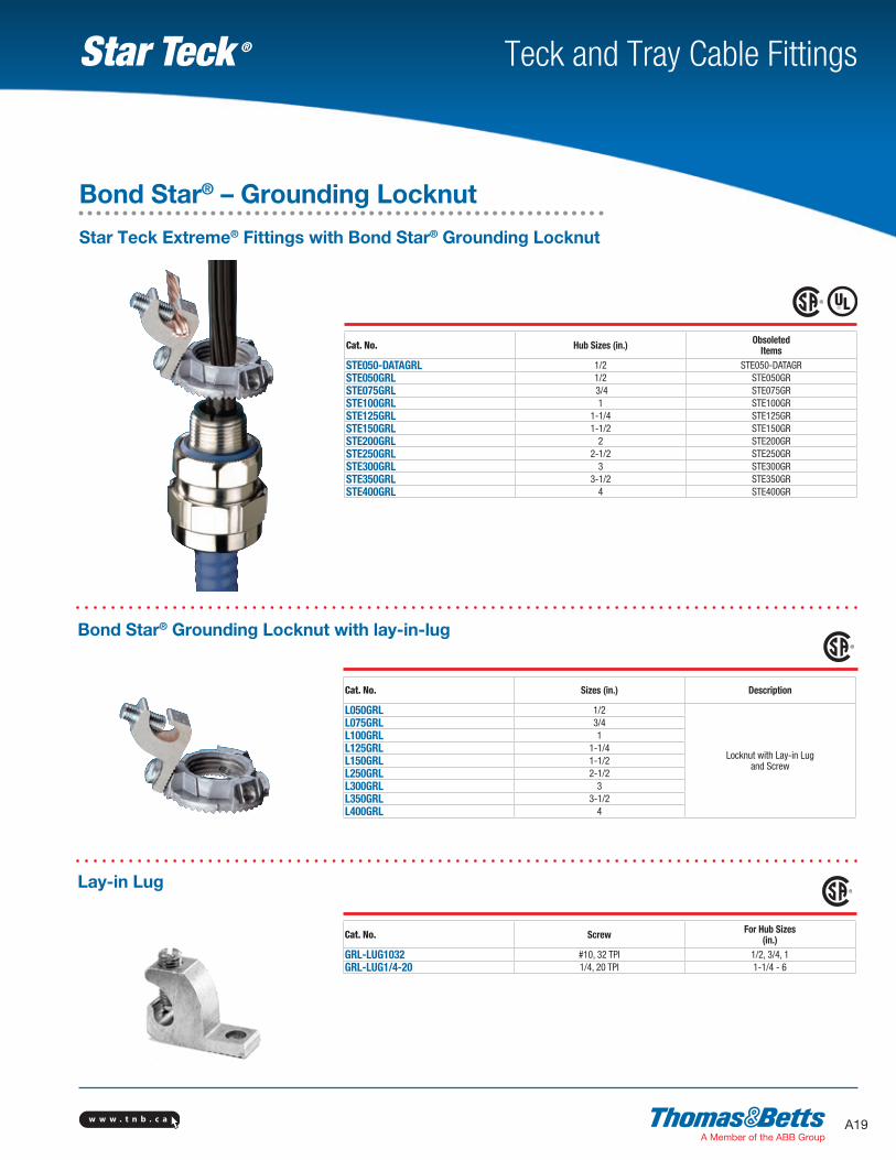
Star Teck Extreme® Fittings with Bond Star® Grounding Locknut
Cat. No. Hub Sizes (in.) Obsoleted Items
STE050-DATAGRL 1/2 STE050-DATAGRSTE050GRL 1/2 STE050GRSTE075GRL 3/4 STE075GRSTE100GRL 1 STE100GRSTE125GRL 1-1/4 STE125GRSTE150GRL 1-1/2 STE150GRSTE200GRL 2 STE200GRSTE250GRL 2-1/2 STE250GRSTE300GRL 3 STE300GRSTE350GRL 3-1/2 STE350GRSTE400GRL 4 STE400GR
Cat. No. Sizes (in.) Description
L050GRL 1/2
Locknut with Lay-in Lug and Screw
L075GRL 3/4L100GRL 1L125GRL 1-1/4L150GRL 1-1/2L250GRL 2-1/2L300GRL 3L350GRL 3-1/2L400GRL 4
Cat. No. Screw For Hub Sizes (in.)
GRL-LUG1032 #10, 32 TPI 1/2, 3/4, 1 GRL-LUG1/4-20 1/4, 20 TPI 1-1/4 - 6
Bond Star® Grounding Locknut with lay-in-lug
Lay-in Lug
Bond Star® – Grounding Locknut
w w w . t n b . c aA20
Teck and Tray Cable FittingsStar Teck ®
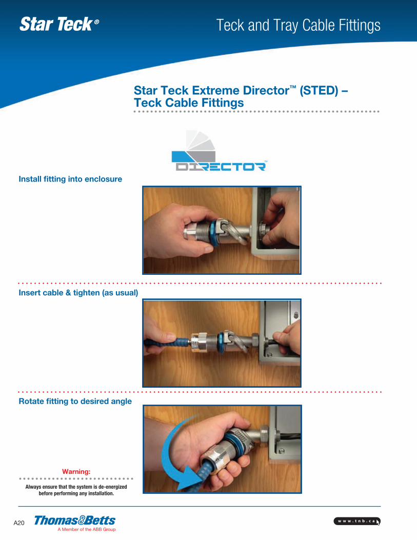
Rotate fitting to desired angle
Install fitting into enclosure
Insert cable & tighten (as usual)
Star Teck Extreme Director™ (STED) – Teck Cable Fittings
Warning: Always ensure that the system is de-energized
before performing any installation.
w w w . t n b . c a A21
Teck and Tray Cable FittingsStar Teck ®
Cat. No.Hub Size(in.)
Gland Torque (lb.-in.)
Range Over Jacket (in.) Range Over Armour (in.) Throat Dia. (Min. in.)Overall
(in.)min. max. min. max. With
Armour StopWithout
Armour Stop
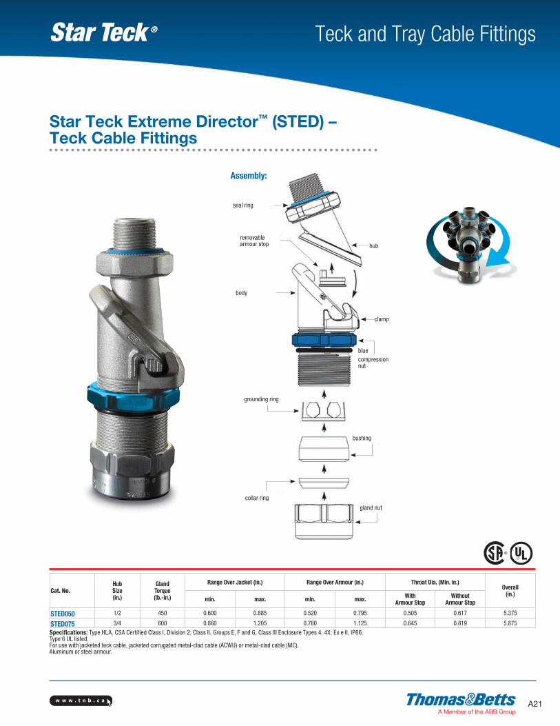
STED050 1/2 450 0.600 0.885 0.520 0.795 0.505 0.617 5.375
STED075 3/4 600 0.860 1.205 0.780 1.125 0.645 0.819 5.875
Specifications: Type HLA. CSA Certified Class I, Division 2; Class II, Groups E, F and G, Class III Enclosure Types 4, 4X; Ex e II, IP66. Type 6 UL listed.For use with jacketed teck cable, jacketed corrugated metal-clad cable (ACWU) or metal-clad cable (MC).Aluminum or steel armour.
Assembly:
bluecompressionnut
collar ring
grounding ring
bushing
clamp
hub
seal ring
body
removablearmour stop
gland nut
Star Teck Extreme Director™ (STED) – Teck Cable Fittings
w w w . t n b . c aA22
Teck and Tray Cable FittingsStar Teck ®
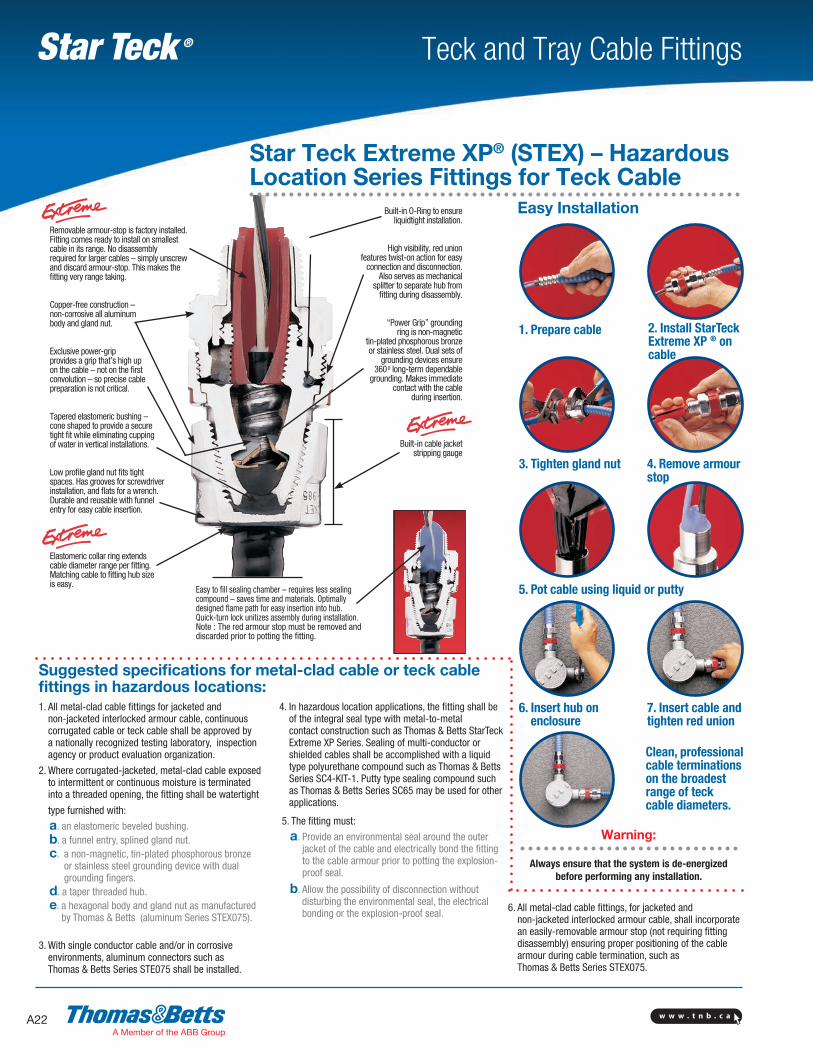
Removable armour-stop is factory installed. Fitting comes ready to install on smallest cable in its range. No disassembly required for larger cables – simply unscrew and discard armour-stop. This makes the fitting very range taking.
Copper-free construction – non-corrosive all aluminum body and gland nut.
Exclusive power-grip provides a grip that’s high up on the cable – not on the first convolution – so precise cable preparation is not critical.
Tapered elastomeric bushing – cone shaped to provide a secure tight fit while elimin ating cupping of water in vertical installations.
Low profile gland nut fits tight spaces. Has grooves for screwdriver installation, and flats for a wrench. Durable and reusable with funnel entry for easy cable insertion.
Elastomeric collar ring extends cable diameter range per fitting. Matching cable to fitting hub size is easy.
Built-in O-Ring to ensure liquidtight installation.
High visibility, red union features twist-on action for easy
connection and disconnection. Also serves as mechanical
splitter to separate hub from fitting during disassembly.
“Power Grip” grounding ring is non-magnetic
tin-plated phosphorous bronze or stainless steel. Dual sets of
grounding devices ensure 3600 long-term dependable
grounding. Makes immediate contact with the cable
during insertion.
Built-in cable jacket stripping gauge
Easy to fill sealing chamber – requires less sealing compound – saves time and materials. Optimally designed flame path for easy insertion into hub. Quick-turn lock unitizes assembly during installation.Note : The red armour stop must be removed and discarded prior to potting the fitting.
Easy Installation
1. Prepare cable 2. Install StarTeck Extreme XP ® on cable
3. Tighten gland nut 4. Remove armour stop
6. Insert hub on enclosure
7. Insert cable and tighten red union
5. Pot cable using liquid or putty
Clean, professional cable terminations on the broadest range of teck cable diameters.
Star Teck Extreme XP® (STEX) – Hazardous Location Series Fittings for Teck Cable
1. All metal-clad cable fittings for jacketed and non-jacketed interlocked armour cable, continuous corrugated cable or teck cable shall be approved by a nationally recognized testing laboratory, inspection agency or product evaluation organization.
2. Where corrugated-jacketed, metal-clad cable exposed to intermittent or continuous moisture is terminated into a threaded opening, the fitting shall be watertight
type furnished with:
a. an elastomeric beveled bushing. b. a funnel entry, splined gland nut. c. a non-magnetic, tin-plated phosphorous bronze
or stainless steel grounding device with dual grounding fingers.
d. a taper threaded hub. e. a hexagonal body and gland nut as manufactured
by Thomas & Betts (aluminum Series STEX075).
3. With single conductor cable and/or in corrosive environments, aluminum connectors such as Thomas & Betts Series STE075 shall be installed.
4. In hazardous location applications, the fitting shall be of the integral seal type with metal-to-metal contact construction such as Thomas & Betts StarTeck Extreme XP Series. Sealing of multi-conductor or shielded cables shall be accomplished with a liquid type polyurethane compound such as Thomas & Betts Series SC4-KIT-1. Putty type sealing compound such as Thomas & Betts Series SC65 may be used for other applications.
5. The fitting must:
a. Provide an environmental seal around the outer jacket of the cable and electrically bond the fitting to the cable armour prior to potting the explosion-proof seal.
b. Allow the possibility of disconnection without disturbing the environmental seal, the electrical bonding or the explosion-proof seal.
Suggested specifications for metal-clad cable or teck cable fittings in hazardous locations:
6. All metal-clad cable fittings, for jacketed and non-jacketed interlocked armour cable, shall incorporate an easily-removable armour stop (not requiring fitting disassembly) ensuring proper positioning of the cable armour during cable termination, such as Thomas & Betts Series STEX075.
Warning: Always ensure that the system is de-energized
before performing any installation.
w w w . t n b . c a A23
Teck and Tray Cable FittingsStar Teck ®
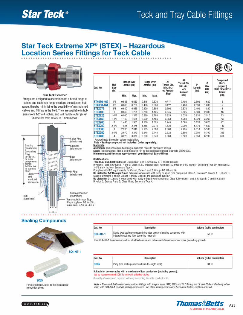
C
A2
Collar Ring (elastomer)
Bushing(elastomer)GroundingRing (3/4 to 1in.-tin plated phosphorous bronze; 1-1/4 in. to 4 in. stainless steel)
Union(red anodized aluminum)
Glandnut (aluminum)
Body (aluminum)
O-Ring (elastomer)
Hub(Aluminum)
Sealing Chamber(Aluminum)
Removable Armour Stop(Polypropylene: 1/2 in.-2 in.)(Aluminum: 2-1/2 in.-4 in.)
A1
B
Ø
Ø Ø
Ø
Ø
Ø
Ø
Ø
Ø
Ø
Star Teck Extreme® fittings are designed to accommodate a broad range of cables and each hub range overlaps the adjacent hub
range, thereby minimizing the possibility of mismatched cables and fittings in the field. They are available in hub sizes from 1/2 to 4 inches, and will handle outer jacket
diameters from 0.525 to 3.870 inches.
Cat. No.Hub Size (in.)
Range Over Jacket (in.)
Range Over Armour (in.)
A1 Throat Dia. Min. (in.)
w/ Armour Stop
A2 Throat Dia. Min. (in.)
w/o Armour
Stop
B* Length
(in.)
C Max. O.D. (in.)
Compound Req’d
(approx.) SC65 /SC4-KIT-1
Liquid (CC)Min. Max. Min. Max.
STX050-462 1/2 0.525 0.650 0.415 0.570 N/A*** 0.400 2.500 1.630 5STX050-464 1/2 0.600 0.760 0.490 0.680 N/A*** 0.480 2.530 1.630 5STEX075 3/4 0.600 0.985 0.520 0.895 0.500 0.670 3.400 1.820 8STEX100 1 0.860 1.205 0.780 1.125 0.645 0.825 3.580 2.300 16STEX125 1-1/4 0.950 1.375 0.870 1.295 0.829 1.076 3.920 2.510 23STEX150 1-1/2 1.150 1.625 0.990 1.465 0.953 1.280 5.020 3.260 43STEX200 2 1.440 1.965 1.280 1.805 1.245 1.565 5.120 3.620 72STEX250 2-1/2 1.825 2.375 1.665 2.215 1.630 2.000 5.170 4.580 147STEX300 3 2.265 2.840 2.105 2.680 2.066 2.495 6.610 5.100 286STEX350 3-1/2 2.670 3.270 2.545 3.145 2.522 2.895 7.380 5.790 366STEX400 4 3.220 3.870 3.090 3.640 3.060 3.520 7.650 6.190 614* Approximate dimension before installation. Note - Sealing compound not included. Order separately.MaterialsAluminum: The above listed catalogue numbers relate to aluminum fittings.Steel: To order a steel fitting, add the suffix «S» to the catalogue number (example STEX050S).Minimum quantities may apply (consult your Regional Sales Office). CertificationsType HLA. CSA Certified Class I, Divisions 1 and 2, Groups A, B, C and D; Class II, Divisions 1 and 2; Groups E, F and G; Class III, SL (integral seal); hub sizes 1/2 through 2-1/2 inches - Enclosure Type 6P; hub sizes 3, 3-1/2 and 4 inches - Enclosure Type 4. Complies with IEC requirements for Class I, Zones 1 and 2, Groups IIC, IIB and IIA.UL Listed for 1/2 through 2 inch hub sizes when used with putty or liquid type compound: Class 1, Division 2, Groups A, B, C and D; Class II, Divisions 1 and 2, Groups F and G; Class III and Enclosure Type 6P.UL Listed for 3-1/2 and 4 when used with putty or liquid type compound: Class 1, Divisions 1 and 2, Groups B, C and D; Class II, Division 2, Groups F and G; Class III and Enclosure Type 4.
Star Teck Extreme XP® (STEX) – Hazardous Location Series Fittings for Teck Cable
Note - Thomas & Betts hazardous locations fittings with integral seals (STX, STEX and HLT Series) are UL and CSA certified only when used with SC4-KIT-1 or SC65 sealing compounds. No other sealing compounds have been tested, certified or listed.
SC65
Cat. No. Description Volume (cubic centimeter)
SC65 Putty type sealing compound (cut-to-length stick) 34 cc
Suitable for use on cables with a maximum of four conductors (including ground). We do not recommend SC65 for use with shielded cables.
Quantity of compound required will vary according to cable conductor fill.
Cat. No. Description Volume (cubic centimeter)
SC4-KIT-1 Liquid type sealing compound (includes pouch of sealing compound with integral spout and fiber damming material). 50 cc
Use SC4-KIT-1 liquid compound for shielded cables and cables with 5 conductors or more (including ground).
Sealing Compounds
For more details, refer to the installation/ instruction sheet.
SC4-KIT-1
w w w . t n b . c aA24
Teck and Tray Cable FittingsStar Teck ®
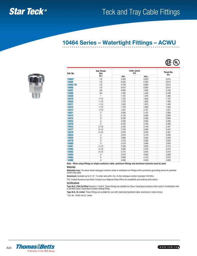
Cat. No.Hub Thread
Size (in.)
Cable Jacket O.D. Throat Dia.
(in.)min. max.
10462* 1/2 0.562 0.625 0.61510464 1/2 0.625 0.760 0.61510465-TB 1/2 0.750 0.885 0.61510466 1/2 0.875 0.985 0.61510467 3/4 0.880 1.065 0.78010468 3/4 1.055 1.205 0.78010469 1 1.187 1.375 1.00010470 1-1/4 1.375 1.625 1.18710550 1-1/4 1.375 1.625 1.40010471 1-1/4 1.625 1.875 1.40010472 1-1/2 1.750 1.965 1.56310473 1-1/2 1.937 2.187 1.62110551 2 2.000 2.187 2.00010474 2 2.156 2.360 2.00010475 2 2.350 2.565 2.00010552 2 2.350 2.565 2.09210476 2 2.535 2.750 2.09210553 2-1/2 2.535 2.750 2.43710477 2-1/2 2.735 2.985 2.43710478 2-1/2 2.970 3.220 2.43710554 3 2.975 3.125 3.05010555 3 3.080 3.250 3.05010479 3 3.210 3.380 3.05010480 3 3.310 3.480 3.05010481 3-1/2 3.430 3.620 3.31010482 3-1/2 3.560 3.750 3.31010483 3-1/2 3.710 3.870 3.31010484 4 3.810 4.000 3.56010485 4 3.930 4.120 3.67010486 4 4.060 4.250 3.800
Note - When using fittings on single conductor cable, aluminum fittings and aluminum locknuts must be used.
Materials
Malleable Iron: The above listed catalogue numbers relate to malleable iron fittings with a protective grounding sleeve for jacketed metal-clad cable.
Aluminum: Available up to 2-1/2”. To order add suffix «AL» to the catalogue number (example 10478AL).
PVC-Coated Aluminum and Steel: Contact your Regional Sales Office for availability and ordering information.
Certifications
Type HLA. CSA Certified Classes I, II and III. These fittings are suitable for Class I hazardous locations when used in combination with a certified Class I hazardous location sealing fitting.
Type OLA. UL Listed. These fittings are suitable for use with interlocked jacketed cable, aluminum or steel armour.
*Cat. No. 10462 not UL Listed
10464 Series – Watertight Fittings – ACWU
w w w . t n b . c a A25
Teck and Tray Cable FittingsStar Teck ®
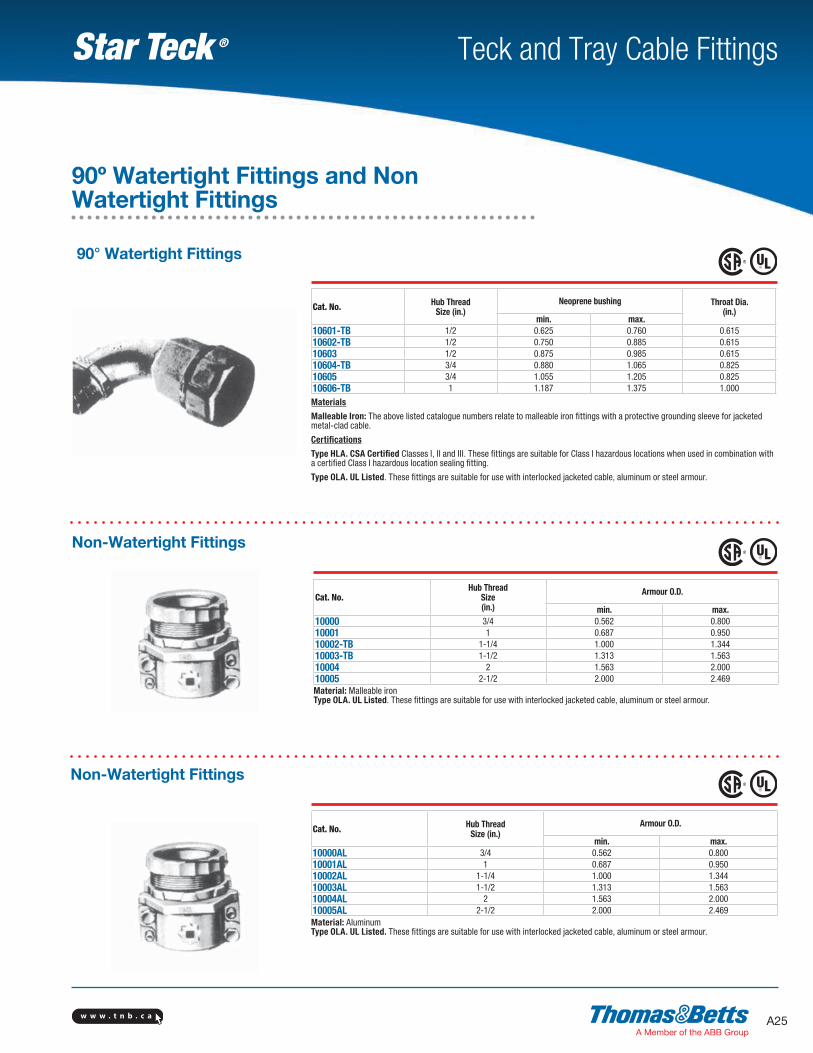
90° Watertight Fittings
Cat. No. Hub Thread Size (in.)
Neoprene bushing Throat Dia. (in.)
min. max. 10601-TB 1/2 0.625 0.760 0.61510602-TB 1/2 0.750 0.885 0.61510603 1/2 0.875 0.985 0.61510604-TB 3/4 0.880 1.065 0.82510605 3/4 1.055 1.205 0.82510606-TB 1 1.187 1.375 1.000
Materials
Malleable Iron: The above listed catalogue numbers relate to malleable iron fittings with a protective grounding sleeve for jacketed metal-clad cable.
Certifications
Type HLA. CSA Certified Classes I, II and III. These fittings are suitable for Class I hazardous locations when used in combination with a certified Class I hazardous location sealing fitting.
Type OLA. UL Listed. These fittings are suitable for use with interlocked jacketed cable, aluminum or steel armour.
Cat. No.Hub Thread
Size (in.)
Armour O.D.
min. max. 10000 3/4 0.562 0.80010001 1 0.687 0.95010002-TB 1-1/4 1.000 1.34410003-TB 1-1/2 1.313 1.56310004 2 1.563 2.00010005 2-1/2 2.000 2.469Material: Malleable ironType OLA. UL Listed. These fittings are suitable for use with interlocked jacketed cable, aluminum or steel armour.
Cat. No. Hub Thread Size (in.)
Armour O.D.
min. max. 10000AL 3/4 0.562 0.80010001AL 1 0.687 0.95010002AL 1-1/4 1.000 1.34410003AL 1-1/2 1.313 1.56310004AL 2 1.563 2.00010005AL 2-1/2 2.000 2.469Material: AluminumType OLA. UL Listed. These fittings are suitable for use with interlocked jacketed cable, aluminum or steel armour.
Non-Watertight Fittings
Non-Watertight Fittings
90º Watertight Fittings and Non Watertight Fittings
w w w . t n b . c aA26
Teck and Tray Cable FittingsStar Teck ®
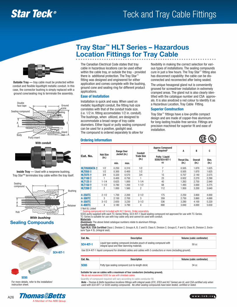
The Canadian Electrical Code states that tray cable in hazardous locations can be used either within the cable tray, or outside the tray - provided there is additional protection. The Tray Star™ fitting was designed and engineered for either application and comes complete with the bushing, ground cone and sealing ring for different product applications.
Ease of InstallationInstallation is quick and easy. When used on metallic liquidtight conduit, the fitting hub size correlates with that of the conduit trade size. (i.e. 1/2 in. fitting accomodates 1/2 in. conduit). The bushings, when utilized, are designed to accommodate a broad range of tray cable diameters. Either liquid or putty sealing compound can be used for a positive, gastight seal. The compound is ordered separately to allow for
flexibility in making the correct selection for vari-ous types of installations. The sealing compounds cure in just a few hours. The Tray Star™ fitting also has disconnect capability: the cable can be dis-connected and reconnected after being sealed.
The unique hexagonal gland nut is conveniently grooved for screwdriver installation in extremely cramped areas. The gland nut is also clearly iden-tified with the catalogue number and CSA approv-als. It is also anodized a red colour to identify it as a Hazardous Location, Tray Cable Fitting.
Superior ConstructionTray Star™ fittings have a low-profile compact design and are made of copper-free aluminum for long-lasting trouble-free service. Fittings are precision machined for superior fit and ease of installation.
With conduit
CA
BDouble face tape
Sealing compound
Ground cone
Sealing ring
Gland nut
Putty insertBody
Sealing compound
Hub
A
B
C
Bushing
Retainer
With bushing
Outside Tray — tray cable must be protected within conduit and flexible liquidtight metallic conduit. In this case, the connector bushing is simply replaced with a ground cone/sealing ring to terminate the assembly.
Ordering Information
Cat. No. Hub Size (in.)
Range Over Jacket (in.) Conduit
Trade Size (in.)
Approx Compound Required* A B C
Putty / Liquid SC65/SC4-KIT-1
ccThroat Dia.
(in.)Overall
(in.)Dim. (in.)min. max.
HLT050DATA † 1/2 0.250 0.310 1/2 7 0.505 1.870 1.625HLT050 † 1/2 0.300 0.400 1/2 7 0.505 1.870 1.625HLT075 † 3/4 0.320 0.570 3/4 15 0.707 2.140 2.075HLT100 † 1 0.400 0.750 1 23 0.932 2.270 2.290HLT125 † 1-1/4 0.625 1.000 1-1/4 45 1.263 2.750 2.840HLT150 † 1-1/2 0.780 1.200 1-1/2 68 1.493 3.000 3.275HLT200 † 2 1.000 1.560 2 112 1.950 3.200 3.640
4-250TC 2-1/2 1.700 2.200 2-1/2 175 2.250 3.800 4.0004-300TC 3 2.150 2.700 3 359 2.750 3.860 4.6904-350TC 3-1/2 2.650 3.230 3-1/2 536 3.280 4.100 5.2204-400TC 4 3.180 3.790 4 690 3.840 4.000 5.630† Not UL Listed* Sealing compound not included with HLT-Series. Order separately.SC65 putty supplied with each TC-Series fitting. SC4-KIT-1 liquid sealing compound not approved for use with TC-Series.TC-Series is suitable for use with tray cable only and cannot be used with conduit.MaterialsAluminum: The above listed catalogue numbers relate to aluminum fittings.CertificationsType HLA. CSA Certified Class I, Division 2, Groups A, B, C and D; Class II, Division 2, Groups E, F and G; Class III, Division 2, Enclo-sure Type 4 SL (integral seal).
Tray Star™ HLT Series – Hazardous Location Fittings for Tray Cable
Note - Thomas & Betts hazardous locations fittings with integral seals (STX, STEX and HLT Series) are UL and CSA certified only when used with SC4-KIT-1 or SC65 sealing compounds. No other sealing compounds have been tested, certified or listed.
SC65
Cat. No. Description Volume (cubic centimeter)
SC65 Putty type sealing compound (cut-to-length stick) 34 cc
Suitable for use on cables with a maximum of four conductors (including ground). We do not recommend SC65 for use with shielded cables.
Quantity of compound required will vary according to cable conductor fill.
Cat. No. Description Volume (cubic centimeter)
SC4-KIT-1 Liquid type sealing compound (includes pouch of sealing compound with integral spout and fiber damming material). 50 cc
Use SC4-KIT-1 liquid compound for shielded cables and cables with 5 conductors or more (including ground).
Sealing Compounds
For more details, refer to the installation/ instruction sheet.
SC4-KIT-1
Inside Tray — Used with a neoprene bushing, Tray StarTM terminates tray cable within the tray itself.
w w w . t n b . c a A27
Teck and Tray Cable FittingsStar Teck ®
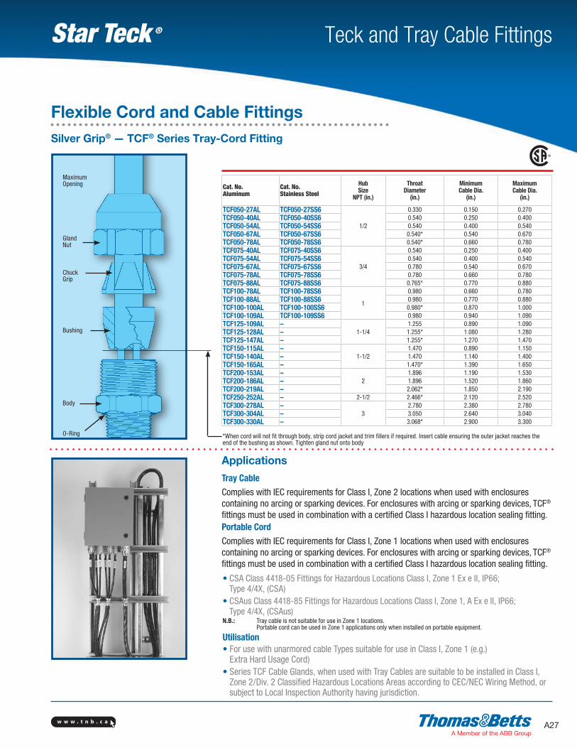
Tray Cable
Complies with IEC requirements for Class I, Zone 2 locations when used with enclosures containing no arcing or sparking devices. For enclosures with arcing or sparking devices, TCF® fittings must be used in combination with a certified Class I hazardous location sealing fitting.Portable Cord
Complies with IEC requirements for Class I, Zone 1 locations when used with enclosures containing no arcing or sparking devices. For enclosures with arcing or sparking devices, TCF® fittings must be used in combination with a certified Class I hazardous location sealing fitting.
*When cord will not fit through body, strip cord jacket and trim fillers if required. Insert cable ensuring the outer jacket reaches the end of the bushing as shown. Tighten gland nut onto body
Applications
• CSA Class 4418-05 Fittings for Hazardous Locations Class I, Zone 1 Ex e II, IP66; Type 4/4X, (CSA)
• CSAus Class 4418-85 Fittings for Hazardous Locations Class I, Zone 1, A Ex e II, IP66; Type 4/4X, (CSAus)
N.B.: Tray cable is not suitable for use in Zone 1 locations. Portable cord can be used in Zone 1 applications only when installed on portable equipment.
Utilisation• For use with unarmored cable Types suitable for use in Class I, Zone 1 (e.g.)
Extra Hard Usage Cord)• Series TCF Cable Glands, when used with Tray Cables are suitable to be installed in Class I,
Zone 2/Div. 2 Classified Hazardous Locations Areas according to CEC/NEC Wiring Method, or subject to Local Inspection Authority having jurisdiction.
O-Ring
Body
Bushing
ChuckGrip
MaximumOpening
GlandNut
Cat. No.Aluminum
Cat. No.Stainless Steel
HubSize
NPT (in.)
Throat Diameter
(in.)
MinimumCable Dia.
(in.)
Maximum Cable Dia.
(in.)
TCF050-27AL TCF050-27SS6
1/2
0.330 0.150 0.270TCF050-40AL TCF050-40SS6 0.540 0.250 0.400TCF050-54AL TCF050-54SS6 0.540 0.400 0.540TCF050-67AL TCF050-67SS6 0.540* 0.540 0.670TCF050-78AL TCF050-78SS6 0.540* 0.660 0.780TCF075-40AL TCF075-40SS6
3/4
0.540 0.250 0.400TCF075-54AL TCF075-54SS6 0.540 0.400 0.540TCF075-67AL TCF075-67SS6 0.780 0.540 0.670TCF075-78AL TCF075-78SS6 0.780 0.660 0.780TCF075-88AL TCF075-88SS6 0.765* 0.770 0.880TCF100-78AL TCF100-78SS6
1
0.980 0.660 0.780TCF100-88AL TCF100-88SS6 0.980 0.770 0.880TCF100-100AL TCF100-100SS6 0.980* 0.870 1.000TCF100-109AL TCF100-109SS6 0.980 0.940 1.090TCF125-109AL –
1-1/41.255 0.890 1.090
TCF125-128AL – 1.255* 1.080 1.280TCF125-147AL – 1.255* 1.270 1.470TCF150-115AL –
1-1/21.470 0.890 1.150
TCF150-140AL – 1.470 1.140 1.400TCF150-165AL – 1.470* 1.390 1.650TCF200-153AL –
21.896 1.190 1.530
TCF200-186AL – 1.896 1.520 1.860TCF200-219AL – 2.062* 1.850 2.190TCF250-252AL – 2-1/2 2.466* 2.120 2.520TCF300-278AL –
32.780 2.380 2.780
TCF300-304AL – 3.050 2.640 3.040TCF300-330AL – 3.068* 2.900 3.300
Flexible Cord and Cable FittingsSilver Grip® — TCF® Series Tray-Cord Fitting

w w w . t n b . c aA28
Teck and Tray Cable FittingsStar Teck ®
AccessoriesFitting SelectorsIdentifying the correct fitting is made easy with Thomas & Betts fitting selectors. Whether for use with power, instrumentation or data transmission cables, simply align the selector with the cable brand, voltage and gauge being used and the appropriate StarTeck® fitting catalogue numbers are identified in the selector window.
Two selectors are currently available through your local electrical distributor or Thomas & Betts Regional Sales Office:• Star Teck® (ST) Series and Star Teck XP® (STX) Series Selector• Star Teck Extreme® (STE) Series and Star Teck Extreme XP® (STEX) Series Selector
Cat. No.: STARTECK RULER
Cat. No.: 2520 RULER
Cat. No.: HLT RULER
Fitting ScalesThese wrap-around belt scales allow end-users to match cable to fitting on site, quickly and easily. The belts wrap around the circumference of the cable, clearly identifying the appropriate size(s) of fitting to use. The belt also incorporates a strip length gauge that indicates the correct length of armour to expose for proper grounding.
The belt scales are available through your local electrical distributor or Thomas & Betts Regional Sales Office.
Cat. No.: STARTECK REG (Blue) (ST) & (STX) Series
Cat. No.: STARTECK EXT (Red) (STE) & (STEX) Series