Embed Size (px)
Citation preview
Submitted on
March 2008
Prepared by
ofStar Cement Meghalaya Ltd.
DRAFTRapid Environmental Impact Assessment
&
Environmental Management Planfor
Clinkerisation Plant of Production Capacity 5300 TPD and Captive Power Plant of capacity 30 MW
at Lumshnong, P.O. Khliehriat,
Jaintia Hills, Meghalaya
Bhagavathi Ana Labs Ltd., Hyderabad

TERMS OF REFERENCE
· F. No. J-11011/754/2007-IA II (I)Government of India
Ministry of Environment and Forests(I.A. Division)
Paryavaran BhawanCGO Complex, Lodhi Road
New Delhi - 110 003
E-mail: [email protected]: 011: 2436 7668
To, /'\_.~/s Star Cement Meghalaya Ltd.Village Lumshnong, Taluka KhliehriatDistrict Jaintia Hills
Meghalaya
E-mail: [email protected]; Fax No. 011-27033824
Dated ihJanuary, 2008
Subject: Cement Clinker Unit (1.50 Million TPA) and Captive Power Plant (30 MW) atVillage Lumshnong, Taluka Khliehriat, District Jaintia Hills, Meghalaya by M/sStar Cement Meghalaya Ltd. - TORs reg.
Ref. : Your letter no. MOEF/SCML/21 06/07-08 dated 21st June, 2007.
Sir,Kindly refer your letter no. MOEF/SCML/2106/07-08 dated 21st June, 2007 alongwith
project documents including Form-I, Pre-feasibility Report and draft 'Terms of Reference' as perthe EIA Notification, 2006. It is noted that proposal is for the Cement Clinker Unit (1.50 MillionTPA) and Captive Power Plant (30 MW) at Village Lumshnong, Taluka Khliehriat, District JaintiaHills, Meghalaya by M/s Star Cement Meghalaya Ltd.
Draft Terms of Reference (TOR) have been discussed and finalized during the 74th
Meeting of the Expert Appraisal Committee (Industry) held during 13th_14th November, 2007 forpreparation of EIA/EMP. Following are the 'TORs':
1. Present land use based on GIS and satellite imagery should be included.2. Information on National Park/Sanctuary/Reserve Forests within 10 km radius of the
project site, if any, should be included.3. List of all the industries located within 10 km radius.4. Site-specific micro-meteorological data including inversion height and mixing height
should be incorporated.5. Information on the status of environment clearance for the Captive lime stone mine
should be included.6. Air quality modeling for the expansion plant including existing cement plant should be
incorporated.7. Sources of secondary emissions, its control and monitoring as per the CPCB
guidelines 'should be included.8. Impact of the transport of the raw materials and end products on the surrounding
environment including agriculturallahd.
-2-
9. A write up on use of high calorific hazardous wastes in kiln and commitmentregarding use of hazardous waste should be included.
10. Sulphur balance for the coal to be used.11. Chemical characterization of RSPM and incorporation of RSPM data. Location of
one AAQMS in downwind direction should be included.12. One-month data for gaseous emissions other than monsoon season should be
included.13. 'Permission' for the drawl of water from water streams and Lubha river and bore
wells will be 3,116 m3/day for CPP and 1,600 m3/day for clinker plant from theconcerned department. Water balance cycle data including quantity of effluentgenerated, recycled and reused and discharged should be included.
14. Surface water quality of nearby river (60 m upstream and 60 m downstream) andother nearby water bodies should be included.
15. Efforts made to minimize use of ground water. A chapter on hydrology study by theState Govt. should be included. Ground water monitoring minimum at 8 locationsshould be included.
16. Surface as well as roof top rain water harvesting and ground water recharge shouldbe included.
17. Scheme of proper storage of fly ash, gypsum and clinker should be included.18. Risk assessment and damage control should be incorporated.19. Occupational health of the workers should be incorporated.20. Green belt development plan for 33 % area as per CPCB guidelines should be
incorporated.21. Socio-economic development activities should be included.22. Rehabilitation and resettlement plan in consultation with the State Govt.23. Compliance to the recommendations mentioned in the CREP guidelines should be
included.
These 'TORs' should be considered for the preparation of draft EIA / EMP report for theCement Clinker Unit (1.50 Million TPA) and Captive Power Plant (30 MW) at VillageLumshnong, Taluka Khliehriat, District Jaintia Hills, Meghalaya in addition to all the relevantinformation as per the 'General Structure of EIA' given in Appendix III and IliA in the EIANotification, 2006. The draft EIA/EMP as per TORs should be submitted to the Chairman,Meghalaya State Pollution Control Board (MSPCB), Shillong for public consultation. TheMSPCB shall conduct the public hearing/public consultation as per the provisions of EIAnotification, 2006.
You are requested to kindly submit the final EIA/EMP prepared as per TORs andincorporating all the issues raised during Public Hearing / Public Consultation to the Ministry forconsidering the proposal for environmental clearance.
Copy to: The Chairman, Meghalaya State· Pollution ControlLumpygngad, Shillong - 793 014, Meghalaya.
~DJ:-(Dr. P.B. Rastogi)Additional Director
Board, 'Arden' Phase-III,
~(Dr. P.B. Rastogi)Additional Director
F. No. J-11011/754/2007-IA II (I)Government of India
Minis.try of Environment and Forests(I.A. Division)
Paryavaran BhawanCGO Complex, Lodhi Road
New Delhi -110 003
To, /M/s Star Cement Meghalaya Ltd.Village Lumshnong, Taluka KhliehriatDistrict Jaintia HillsMeghalaya
E-mail: [email protected]: 011: 2436 7668
Dated 1ih March, 2008
Sir,
E-mail: [email protected] [email protected] ; Fax No. : 011-27033824
Subject: Cement Clinker Unit (1.75 Million TPA) and Captive Power Plant (30 MW) atVillage Lumshnong, Taluka Khliehriat, District Jaintia Hills, Meghalaya by MIsStar Cement Meghalaya ltd. - TORs reg.
Ref. : 1. Ministry's even no. letter dated 7th January, 2008.2. Your letter no. SCMLlMOEFI 2007-08 dated 18th February, 2007.
Kindly refer your letter no. SCML/MOEF/ 2007-08 dated 18th February, 2007 whereinyou have requested for the permission to enhance clinker production from 1.50 TPA Clinker to1.75 TPA with no increase in cost and power production from Captive Power Plant (30 MW) tomake use of built-in margins.
Draft Terms of Reference (TOR) discussed and finalized during the 74th Meeting of theExpert Appraisal Committee (Industry) held during 13th_14th November, 2007 for preparation ofEIA/EMP for the Cement Clinker Unit (1. 50 Million TPA) and Captive Power Plant (30 MW) willnow be for the enhanced capacity of the Cement Clinker Unit (1.75 Million TPA) and CaptivePower Plant (30 MW) at Village Lumshnong, Taluka Khliehriat, District Jaintia Hills, Meghalayasubject to no increase in cost of the project, power production from Captive Power Plant (30MW) and pollution load.
You are now requested to prepare draft EIA/EMP report as per the 'TORs' awarded videMinistry's even no. letter dated th January, 2008 for the Cement Clinker Unit (1.75 Million TPA)and Captive Power Plant (30 MW) at Village Lumshnong, Taluka Khliehriat, District Jaintia Hills,Meghalaya in addition to all the relevant information as per the 'General Structure of EIA' givenin Appendix III and IliA in the EIA Notification, 2006. The draft EIAIEMP as per TORs should besubmitted to the Chairman, Meghalaya State Pollution Control Board (MSPCB), Shillong forpublic consultation. The MSPCB shall conduct the public hearing/public consultation as per theprovisions of EIA notification, 2006.
You are also requested to kindly submit the final EIA/EMP prepared as per TORs andincorporating all the issues raised during Public Hearing / Public Consultation to the Ministry for
considering the proposal for environmental clearance. ~ / . 0. ~~\'}~'l\CD
(Dr. .B. Rastogi)Director
Copy to: The Chairman, Meghalaya State Pollution Control Board, 'Arden' Phase-III,
Lumpygngad, Shillong - 793 014, Meghalaya. n ~}~0~v\>\(Dr. P.B. Rastogi)
Director

COMPLIANCE OF TERMS OF REFERENCE
S.No MoEF-TOR Point Compliance status 1 Hydrogeological Environment
a Information and data on hydrogeology and geology of the project area and preparation of hydro-morphological map of the project area
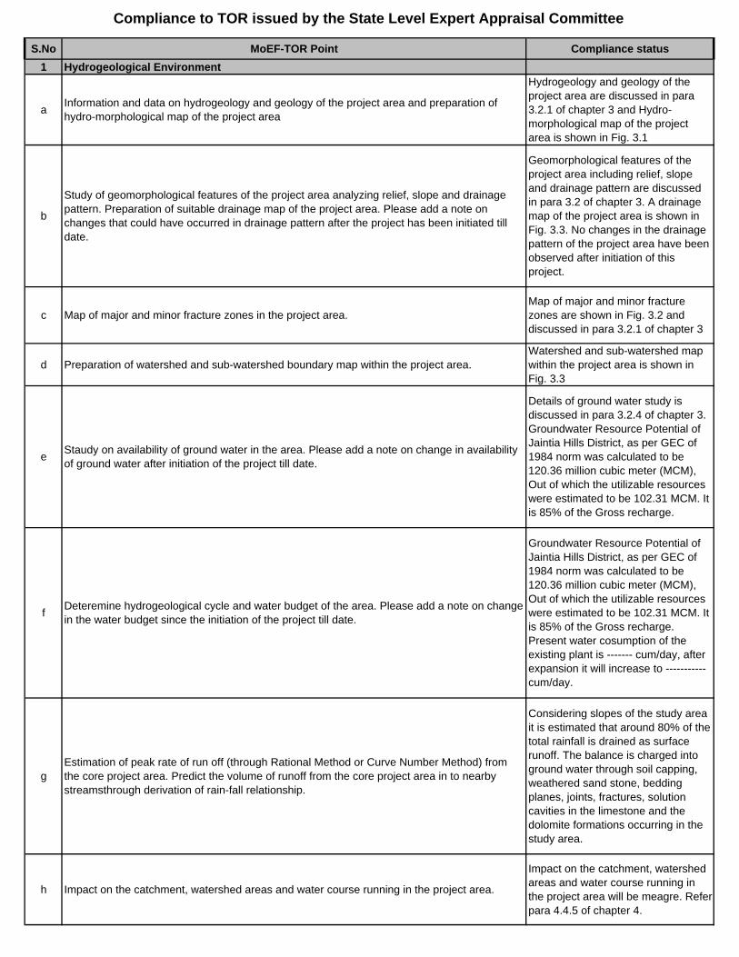
Hydrogeology and geology of the project area are discussed in para 3.2.1 of chapter 3 and Hydro-morphological map of the project area is shown in Fig. 3.1
b
Study of geomorphological features of the project area analyzing relief, slope and drainage pattern. Preparation of suitable drainage map of the project area. Please add a note on changes that could have occurred in drainage pattern after the project has been initiated till date.
Geomorphological features of the project area including relief, slope and drainage pattern are discussed in para 3.2 of chapter 3. A drainage map of the project area is shown in Fig. 3.3. No changes in the drainage pattern of the project area have been observed after initiation of this project.
c Map of major and minor fracture zones in the project area.Map of major and minor fracture zones are shown in Fig. 3.2 and discussed in para 3.2.1 of chapter 3
d Preparation of watershed and sub-watershed boundary map within the project area.Watershed and sub-watershed map within the project area is shown in Fig. 3.3
e Staudy on availability of ground water in the area. Please add a note on change in availability of ground water after initiation of the project till date.
Details of ground water study is discussed in para 3.2.4 of chapter 3. Groundwater Resource Potential of Jaintia Hills District, as per GEC of 1984 norm was calculated to be 120.36 million cubic meter (MCM), Out of which the utilizable resources were estimated to be 102.31 MCM. It is 85% of the Gross recharge.
f Deteremine hydrogeological cycle and water budget of the area. Please add a note on change in the water budget since the initiation of the project till date.
Groundwater Resource Potential of Jaintia Hills District, as per GEC of 1984 norm was calculated to be 120.36 million cubic meter (MCM), Out of which the utilizable resources were estimated to be 102.31 MCM. It is 85% of the Gross recharge. Present water cosumption of the existing plant is ------- cum/day, after expansion it will increase to -----------cum/day.
gEstimation of peak rate of run off (through Rational Method or Curve Number Method) from the core project area. Predict the volume of runoff from the core project area in to nearby streamsthrough derivation of rain-fall relationship.
Considering slopes of the study area it is estimated that around 80% of the total rainfall is drained as surface runoff. The balance is charged into ground water through soil capping, weathered sand stone, bedding planes, joints, fractures, solution cavities in the limestone and the dolomite formations occurring in the study area.
h Impact on the catchment, watershed areas and water course running in the project area.
Impact on the catchment, watershed areas and water course running in the project area will be meagre. Refer para 4.4.5 of chapter 4.
Compliance to TOR issued by the State Level Expert Appraisal Committee
S.No MoEF-TOR Point Compliance status
Compliance to TOR issued by the State Level Expert Appraisal Committee
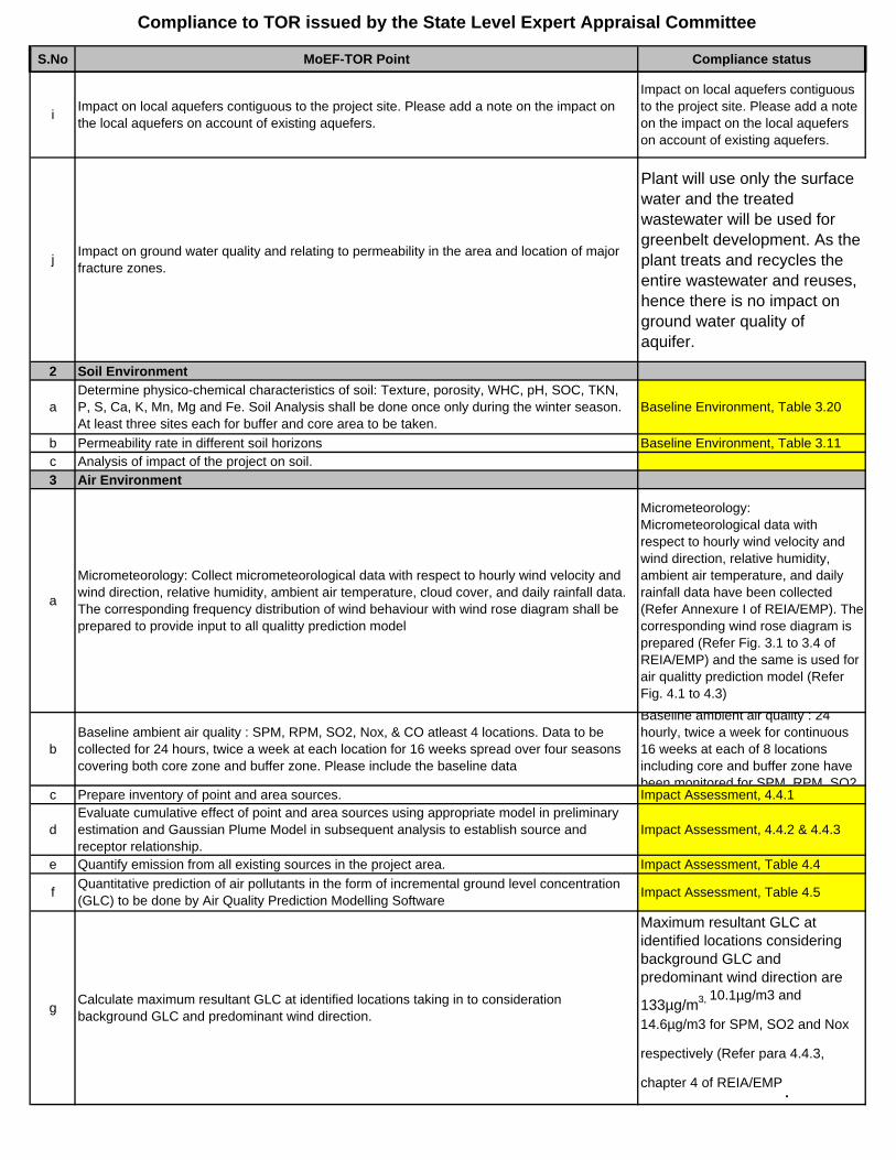
i Impact on local aquefers contiguous to the project site. Please add a note on the impact on the local aquefers on account of existing aquefers.
Impact on local aquefers contiguous to the project site. Please add a note on the impact on the local aquefers on account of existing aquefers.
j Impact on ground water quality and relating to permeability in the area and location of major fracture zones.
Plant will use only the surface water and the treated wastewater will be used for greenbelt development. As the plant treats and recycles the entire wastewater and reuses, hence there is no impact on ground water quality of aquifer.
2 Soil Environment
aDetermine physico-chemical characteristics of soil: Texture, porosity, WHC, pH, SOC, TKN, P, S, Ca, K, Mn, Mg and Fe. Soil Analysis shall be done once only during the winter season. At least three sites each for buffer and core area to be taken.
Baseline Environment, Table 3.20
b Permeability rate in different soil horizons Baseline Environment, Table 3.11c Analysis of impact of the project on soil.3 Air Environment
a
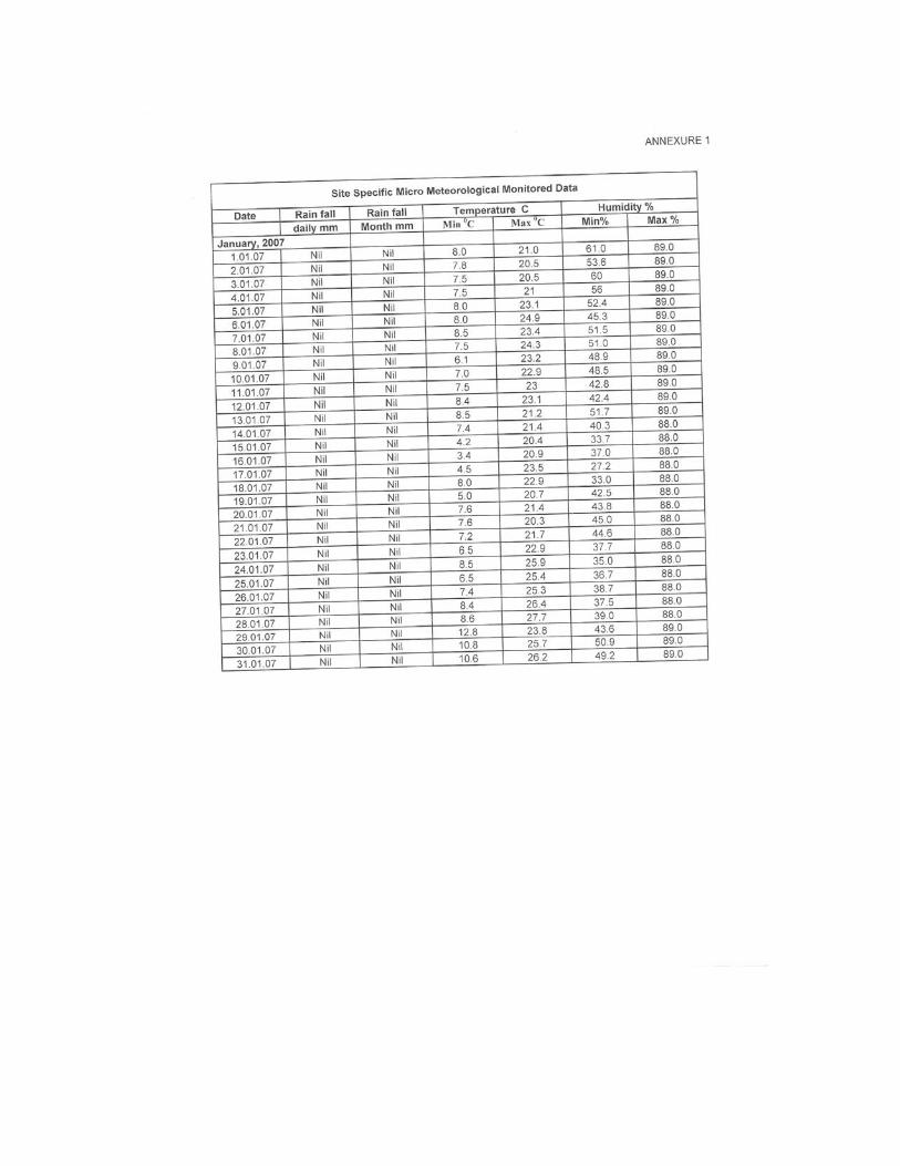
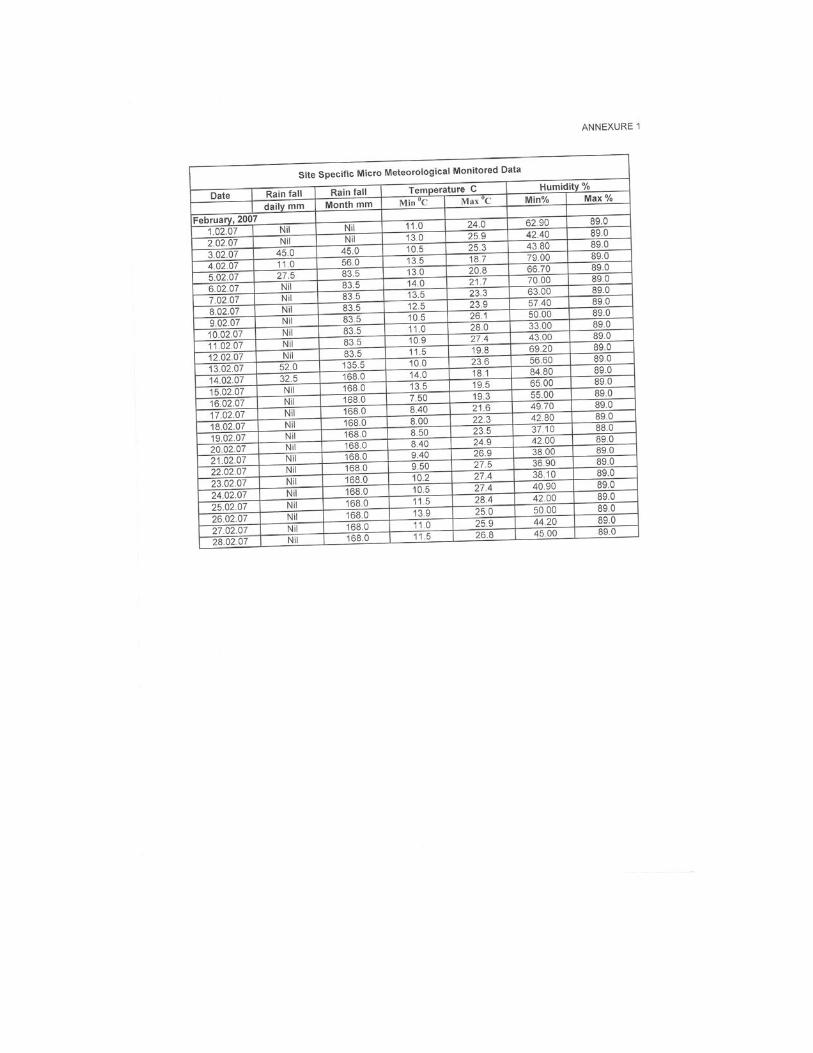
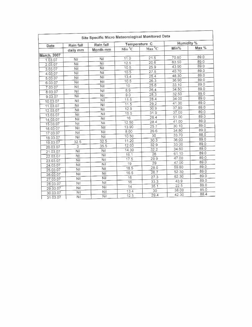
Micrometeorology: Collect micrometeorological data with respect to hourly wind velocity and wind direction, relative humidity, ambient air temperature, cloud cover, and daily rainfall data. The corresponding frequency distribution of wind behaviour with wind rose diagram shall be prepared to provide input to all qualitty prediction model
Micrometeorology: Micrometeorological data with respect to hourly wind velocity and wind direction, relative humidity, ambient air temperature, and daily rainfall data have been collected (Refer Annexure I of REIA/EMP). The corresponding wind rose diagram is prepared (Refer Fig. 3.1 to 3.4 of REIA/EMP) and the same is used for air qualitty prediction model (Refer Fig. 4.1 to 4.3)
bBaseline ambient air quality : SPM, RPM, SO2, Nox, & CO atleast 4 locations. Data to be collected for 24 hours, twice a week at each location for 16 weeks spread over four seasons covering both core zone and buffer zone. Please include the baseline data
Baseline ambient air quality : 24 hourly, twice a week for continuous 16 weeks at each of 8 locations including core and buffer zone have been monitored for SPM RPM SO2
c Prepare inventory of point and area sources. Impact Assessment, 4.4.1
dEvaluate cumulative effect of point and area sources using appropriate model in preliminary estimation and Gaussian Plume Model in subsequent analysis to establish source and receptor relationship.
Impact Assessment, 4.4.2 & 4.4.3
e Quantify emission from all existing sources in the project area. Impact Assessment, Table 4.4
f Quantitative prediction of air pollutants in the form of incremental ground level concentration (GLC) to be done by Air Quality Prediction Modelling Software Impact Assessment, Table 4.5
g Calculate maximum resultant GLC at identified locations taking in to consideration background GLC and predominant wind direction.
Maximum resultant GLC at identified locations considering background GLC and predominant wind direction are
133µg/m3, 10.1µg/m3 and
14.6µg/m3 for SPM, SO2 and Nox
respectively (Refer para 4.4.3,
chapter 4 of REIA/EMP.
S.No MoEF-TOR Point Compliance status
Compliance to TOR issued by the State Level Expert Appraisal Committee
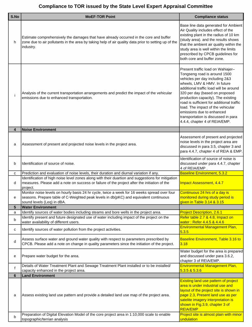
hEstimate comprehensively the damages that have already occurred in the core and buffer zone due to air pollutants in the area by taking help of air quality data prior to setting up of the industry.
Base line data generated for Ambient Air Quality includes effect of the existing plant in the radius of 10 km (study area). and the results shows that the ambient air quality within the study area is well within the limits prescribed by CPCB guidelines for both core and buffer zone.
i Analysis of the current transportation arrangements and predict the impact of the vehicular emissions due to enhanced transportation.
Present traffic load on Wahiajer– Tongseng road is around 1500 vehicles per day including 2&3 wheels, LMV & HMV. In future additional traffic load will be around 320 per day (based on proposed production capacity). The existing road is sufficient for additional traffic load. The impact of the vehicular emissions due to enhanced transportation is discussed in para 4.4.4, chapter 4 of REIA/EMP.
4 Noise Environment
a Assessment of present and projected noise levels in the project area.
Assessment of present and projected noise levels in the project area are discussed in para 3.5, chapter 3 and para 4.4.7, chapter 4 of REIA & EMP.
b Identification of source of noise.Identification of source of noise is discussed under para 4.4.7, chapter 4 of REIA/EMP .
c Prediction and evaluation of noise levels, their duration and diurnal variation if any. Baseline Environment, 5.3.2
dIdentification of high noise level zones along with their duartion and suggestions for mitigation measures. Please add a note on success or failure of the project after the initiation of the project.
Impact Assessment, 4.4.7
eMonitor noise levels on hourly basis 24 hr cycle, twice a week for 16 weeks spread over four seasons. Prepare table of C-Weighted peak levels in db(pKC) and equivalent continuous sound levels (Leq) in dBA.
Continuous 24 hrs of a day is monitored during study period is given in Table 3.14 & 3.15
5 Water Environmenta Identify sources of water bodies including steams and bore wells in the project area. Project Description, 2.6.1
b Identify present and future designated use of water including impact of the project on the water availability of different users.
Refer table 2.7 & 4.8, Impact on water : Refer 4.4.5 & 4.4.6
c Identify sources of water pollution from the project activities. Environmental Management Plan, 5.3.5
d Assess surface water and ground water quality with respect to parameters prescribed by CPCB. Please add a note on change in quality parameters since the initiation of the project.
Baseline Environment, Table 3.16 to 3.18
e Prepare water budget for the area.Water budget for the area is prepared and discussed under para 3.6.2, chapter 3 of REIA/EMP.
f Details of Water Treatment Plant and Sewage Treatment Plant installed or to be installed/ capacity enhanced in the project area.
Environmental Management Plan, 5.3.5 & 5.3.6
6 Land Environment
a Assess existing land use pattern and provide a detailed land use map of the project area.
Existing land use pattern of project area is under industrial use and layout of the project site is shown in page 2.3, Present land use as per satelite imagery interpretation is shown in Fig.3.9, chapter 3 of REIA/EMP
b Preparation of Digital Elevation Model of the core project area in 1:10,000 scale to enable topographic/terrian analysis
Project site is almost plain with minor undulation
S.No MoEF-TOR Point Compliance status
Compliance to TOR issued by the State Level Expert Appraisal Committee
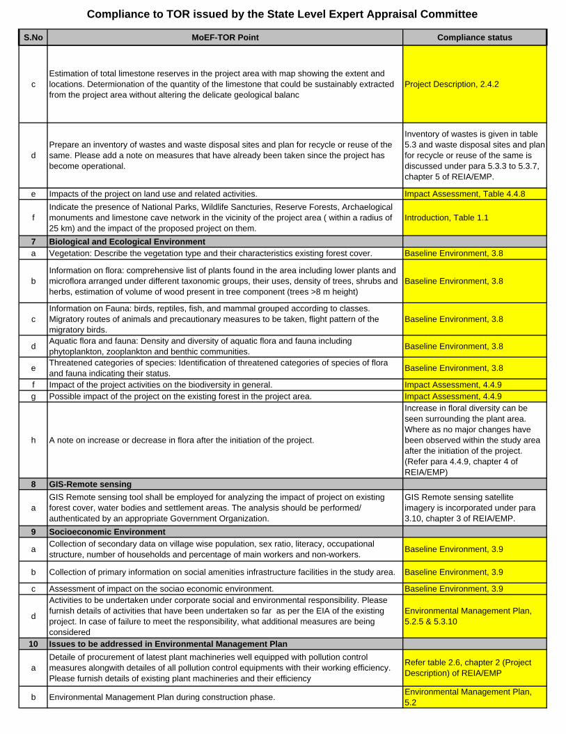
cEstimation of total limestone reserves in the project area with map showing the extent and locations. Determionation of the quantity of the limestone that could be sustainably extracted from the project area without altering the delicate geological balanc
Project Description, 2.4.2
dPrepare an inventory of wastes and waste disposal sites and plan for recycle or reuse of the same. Please add a note on measures that have already been taken since the project has become operational.
Inventory of wastes is given in table 5.3 and waste disposal sites and plan for recycle or reuse of the same is discussed under para 5.3.3 to 5.3.7, chapter 5 of REIA/EMP.
e Impacts of the project on land use and related activities. Impact Assessment, Table 4.4.8
fIndicate the presence of National Parks, Wildlife Sancturies, Reserve Forests, Archaelogical monuments and limestone cave network in the vicinity of the project area ( within a radius of 25 km) and the impact of the proposed project on them.
Introduction, Table 1.1
7 Biological and Ecological Environmenta Vegetation: Describe the vegetation type and their characteristics existing forest cover. Baseline Environment, 3.8
bInformation on flora: comprehensive list of plants found in the area including lower plants and microflora arranged under different taxonomic groups, their uses, density of trees, shrubs and herbs, estimation of volume of wood present in tree component (trees >8 m height)
Baseline Environment, 3.8
cInformation on Fauna: birds, reptiles, fish, and mammal grouped according to classes. Migratory routes of animals and precautionary measures to be taken, flight pattern of the migratory birds.
Baseline Environment, 3.8
d Aquatic flora and fauna: Density and diversity of aquatic flora and fauna including phytoplankton, zooplankton and benthic communities. Baseline Environment, 3.8
e Threatened categories of species: Identification of threatened categories of species of flora and fauna indicating their status. Baseline Environment, 3.8
f Impact of the project activities on the biodiversity in general. Impact Assessment, 4.4.9g Possible impact of the project on the existing forest in the project area. Impact Assessment, 4.4.9
h A note on increase or decrease in flora after the initiation of the project.
Increase in floral diversity can be seen surrounding the plant area. Where as no major changes have been observed within the study area after the initiation of the project. (Refer para 4.4.9, chapter 4 of REIA/EMP)
8 GIS-Remote sensing
aGIS Remote sensing tool shall be employed for analyzing the impact of project on existing forest cover, water bodies and settlement areas. The analysis should be performed/ authenticated by an appropriate Government Organization.
GIS Remote sensing satellite imagery is incorporated under para 3.10, chapter 3 of REIA/EMP.
9 Socioeconomic Environment
a Collection of secondary data on village wise population, sex ratio, literacy, occupational structure, number of households and percentage of main workers and non-workers. Baseline Environment, 3.9
b Collection of primary information on social amenities infrastructure facilities in the study area. Baseline Environment, 3.9
c Assessment of impact on the sociao economic environment. Baseline Environment, 3.9
d
Activities to be undertaken under corporate social and environmental responsibility. Please furnish details of activities that have been undertaken so far as per the EIA of the existing project. In case of failure to meet the responsibility, what additional measures are being considered
Environmental Management Plan, 5.2.5 & 5.3.10
10 Issues to be addressed in Environmental Management Plan
aDetaile of procurement of latest plant machineries well equipped with pollution control measures alongwith detailes of all pollution control equipments with their working efficiency. Please furnish details of existing plant machineries and their efficiency
Refer table 2.6, chapter 2 (Project Description) of REIA/EMP
b Environmental Management Plan during construction phase. Environmental Management Plan, 5.2
S.No MoEF-TOR Point Compliance status
Compliance to TOR issued by the State Level Expert Appraisal Committee
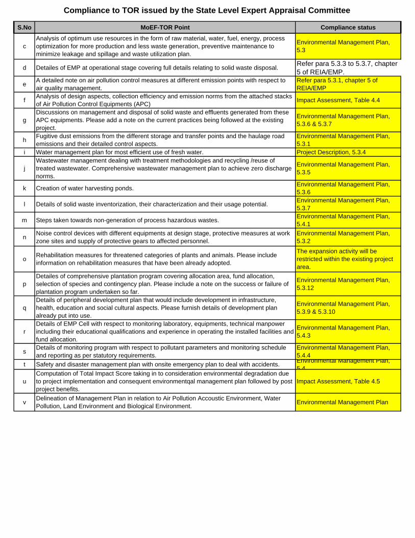
cAnalysis of optimum use resources in the form of raw material, water, fuel, energy, process optimization for more production and less waste generation, preventive maintenance to minimize leakage and spillage and waste utilization plan.
Environmental Management Plan, 5.3
d Detailes of EMP at operational stage covering full details relating to solid waste disposal. Refer para 5.3.3 to 5.3.7, chapter 5 of REIA/EMP.
e A detailed note on air pollution control measures at different emission points with respect to air quality management.
Refer para 5.3.1, chapter 5 of REIA/EMP
f Analysis of design aspects, collection efficiency and emission norms from the attached stacks of Air Pollution Control Equipments (APC) Impact Assessment, Table 4.4
g Discussions on management and disposal of solid waste and effluents generated from these APC equipments. Please add a note on the current practices being followed at the existing project.
Environmental Management Plan, 5.3.6 & 5.3.7
h Fugitive dust emissions from the different storage and transfer points and the haulage road emissions and their detailed control aspects.
Environmental Management Plan, 5.3.1
i Water management plan for most efficient use of fresh water. Project Description, 5.3.4
jWastewater management dealing with treatment methodologies and recycling /reuse of treated wastewater. Comprehensive wastewater management plan to achieve zero discharge norms.
Environmental Management Plan, 5.3.5
k Creation of water harvesting ponds. Environmental Management Plan, 5.3.6
l Details of solid waste inventorization, their characterization and their usage potential. Environmental Management Plan, 5.3.7
m Steps taken towards non-generation of process hazardous wastes. Environmental Management Plan, 5.4.1
n Noise control devices with different equipments at design stage, protective measures at work zone sites and supply of protective gears to affected personnel.
Environmental Management Plan, 5.3.2
o Rehabilitation measures for threatened categories of plants and animals. Please include information on rehabilitation measures that have been already adopted.
The expansion activity will be restricted within the existing project area.
pDetailes of comprehensive plantation program covering allocation area, fund allocation, selection of species and contingency plan. Please include a note on the success or failure of plantation program undertaken so far.
Environmental Management Plan, 5.3.12
qDetails of peripheral development plan that would include development in infrastructure, health, education and social cultural aspects. Please furnish details of development plan already put into use.
Environmental Management Plan, 5.3.9 & 5.3.10
rDetails of EMP Cell with respect to monitoring laboratory, equipments, technical manpower including their educational qualifications and experience in operating the installed facilities and fund allocation.
Environmental Management Plan, 5.4.3
s Details of monitoring program with respect to pollutant parameters and monitoring schedule and reporting as per statutory requirements.
Environmental Management Plan, 5.4.4
t Safety and disaster management plan with onsite emergency plan to deal with accidents. Environmental Management Plan, 5 4
uComputation of Total Impact Score taking in to consideration environmental degradation due to project implementation and consequent environmentqal management plan followed by post project benefits.
Impact Assessment, Table 4.5
v Delineation of Management Plan in relation to Air Pollution Accoustic Environment, Water Pollution, Land Environment and Biological Environment. Environmental Management Plan

EXECUTIVE SUMMARY
EExxeeccuuttiivvee SSuummmmaarryy
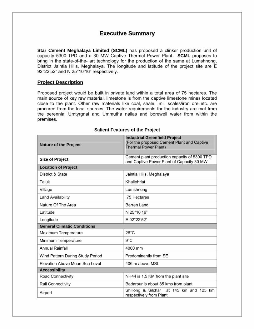
Star Cement Meghalaya Limited (SCML) has proposed a clinker production unit of capacity 5300 TPD and a 30 MW Captive Thermal Power Plant. SCML proposes to bring in the state-of-the- art technology for the production of the same at Lumshnong, District Jaintia Hills, Meghalaya. The longitude and latitude of the project site are E 92°22’52” and N 25°10’16” respectively. Project Description Proposed project would be built in private land within a total area of 75 hectares. The main source of key raw material, limestone is from the captive limestone mines located close to the plant. Other raw materials like coal, shale mill scales/iron ore etc. are procured from the local sources. The water requirements for the industry are met from the perennial Umtyrgnai and Ummutha nallas and borewell water from within the premises.
Salient Features of the Project
Nature of the Project Industrial Greenfield Project (For the proposed Cement Plant and Captive Thermal Power Plant)
Size of Project Cement plant production capacity of 5300 TPD and Captive Power Plant of Capacity 30 MW
Location of Project District & State Jaintia Hills, Meghalaya
Taluk Khaliehriat
Village Lumshnong
Land Availability 75 Hectares
Nature Of The Area Barren Land
Latitude N 25°10’16”
Longitude E 92°22’52” General Climatic Conditions Maximum Temperature 26°C
Minimum Temperature 9°C
Annual Rainfall 4000 mm
Wind Pattern During Study Period Predominantly from SE
Elevation Above Mean Sea Level 406 m above MSL Accessibility Road Connectivity NH44 is 1.5 KM from the plant site
Rail Connectivity Badarpur is about 85 kms from plant
Airport Shillong & Silchar at 145 km and 125 km respectively from Plant
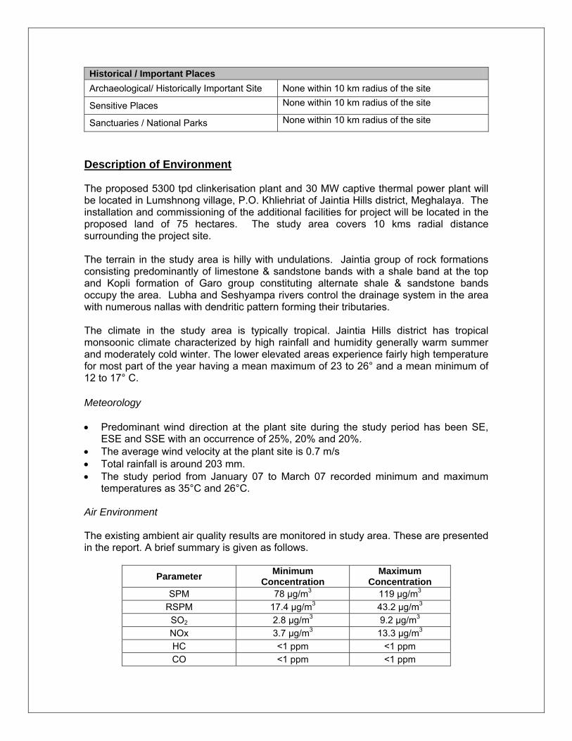
Historical / Important Places Archaeological/ Historically Important Site None within 10 km radius of the site
Sensitive Places None within 10 km radius of the site
Sanctuaries / National Parks None within 10 km radius of the site
Description of Environment The proposed 5300 tpd clinkerisation plant and 30 MW captive thermal power plant will be located in Lumshnong village, P.O. Khliehriat of Jaintia Hills district, Meghalaya. The installation and commissioning of the additional facilities for project will be located in the proposed land of 75 hectares. The study area covers 10 kms radial distance surrounding the project site. The terrain in the study area is hilly with undulations. Jaintia group of rock formations consisting predominantly of limestone & sandstone bands with a shale band at the top and Kopli formation of Garo group constituting alternate shale & sandstone bands occupy the area. Lubha and Seshyampa rivers control the drainage system in the area with numerous nallas with dendritic pattern forming their tributaries. The climate in the study area is typically tropical. Jaintia Hills district has tropical monsoonic climate characterized by high rainfall and humidity generally warm summer and moderately cold winter. The lower elevated areas experience fairly high temperature for most part of the year having a mean maximum of 23 to 26° and a mean minimum of 12 to 17° C. Meteorology • Predominant wind direction at the plant site during the study period has been SE,
ESE and SSE with an occurrence of 25%, 20% and 20%. • The average wind velocity at the plant site is 0.7 m/s • Total rainfall is around 203 mm. • The study period from January 07 to March 07 recorded minimum and maximum
temperatures as 35°C and 26°C. Air Environment The existing ambient air quality results are monitored in study area. These are presented in the report. A brief summary is given as follows.
Parameter Minimum Concentration
Maximum Concentration
SPM 78 μg/m3 119 μg/m3
RSPM 17.4 μg/m3 43.2 μg/m3
SO2 2.8 μg/m3 9.2 μg/m3
NOx 3.7 μg/m3 13.3 μg/m3
HC <1 ppm <1 ppm CO <1 ppm <1 ppm
• The ambient air quality monitoring results suggest that the SPM, RPM, SO2, NOx, HC and CO monitored at all the locations were found to be within the NAAQ Standards.
• Air pollution control equipment and measures would be in place in the plant to
ensure that the air pollution concentration does not exceed the prescribed limits stipulated by State Pollution Control Board, CPCB & MoEF.
Noise Environment • The noise levels were within the prescribed limits when compared with Ambient Air
Quality Standards in respect of Noise. • Noise control is achieved by selecting a low noise producing equipment, which would
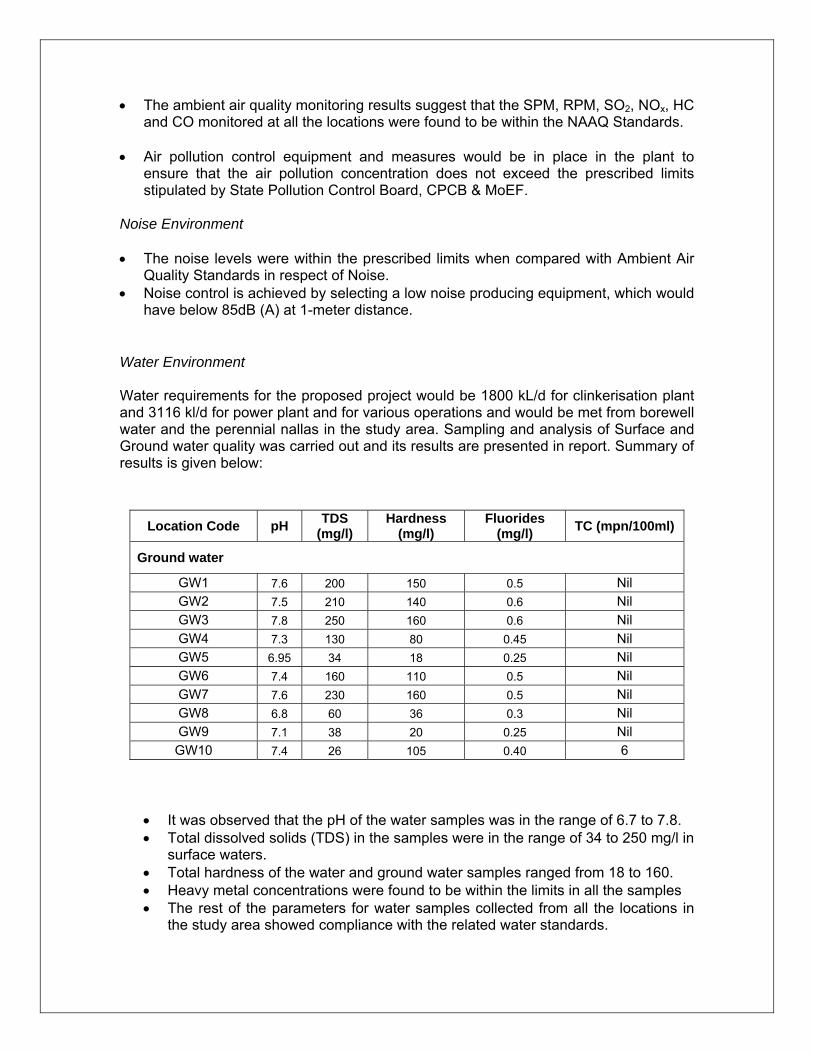
have below 85dB (A) at 1-meter distance. Water Environment Water requirements for the proposed project would be 1800 kL/d for clinkerisation plant and 3116 kl/d for power plant and for various operations and would be met from borewell water and the perennial nallas in the study area. Sampling and analysis of Surface and Ground water quality was carried out and its results are presented in report. Summary of results is given below:
• It was observed that the pH of the water samples was in the range of 6.7 to 7.8. • Total dissolved solids (TDS) in the samples were in the range of 34 to 250 mg/l in
surface waters. • Total hardness of the water and ground water samples ranged from 18 to 160. • Heavy metal concentrations were found to be within the limits in all the samples • The rest of the parameters for water samples collected from all the locations in
the study area showed compliance with the related water standards.
Location Code pH TDS (mg/l)
Hardness (mg/l)
Fluorides (mg/l) TC (mpn/100ml)
Ground water
GW1 7.6 200 150 0.5 Nil GW2 7.5 210 140 0.6 Nil GW3 7.8 250 160 0.6 Nil GW4 7.3 130 80 0.45 Nil GW5 6.95 34 18 0.25 Nil GW6 7.4 160 110 0.5 Nil GW7 7.6 230 160 0.5 Nil GW8 6.8 60 36 0.3 Nil GW9 7.1 38 20 0.25 Nil GW10 7.4 26 105 0.40 6
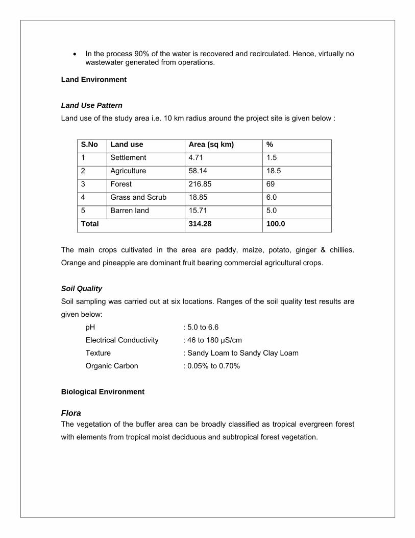
• In the process 90% of the water is recovered and recirculated. Hence, virtually no wastewater generated from operations.
Land Environment Land Use Pattern
Land use of the study area i.e. 10 km radius around the project site is given below :
S.No Land use Area (sq km) %
1 Settlement 4.71 1.5
2 Agriculture 58.14 18.5
3 Forest 216.85 69
4 Grass and Scrub 18.85 6.0
5 Barren land 15.71 5.0
Total 314.28 100.0
The main crops cultivated in the area are paddy, maize, potato, ginger & chillies.
Orange and pineapple are dominant fruit bearing commercial agricultural crops.
Soil Quality
Soil sampling was carried out at six locations. Ranges of the soil quality test results are
given below:
pH : 5.0 to 6.6
Electrical Conductivity : 46 to 180 μS/cm
Texture : Sandy Loam to Sandy Clay Loam
Organic Carbon : 0.05% to 0.70%
Biological Environment
Flora The vegetation of the buffer area can be broadly classified as tropical evergreen forest
with elements from tropical moist deciduous and subtropical forest vegetation.
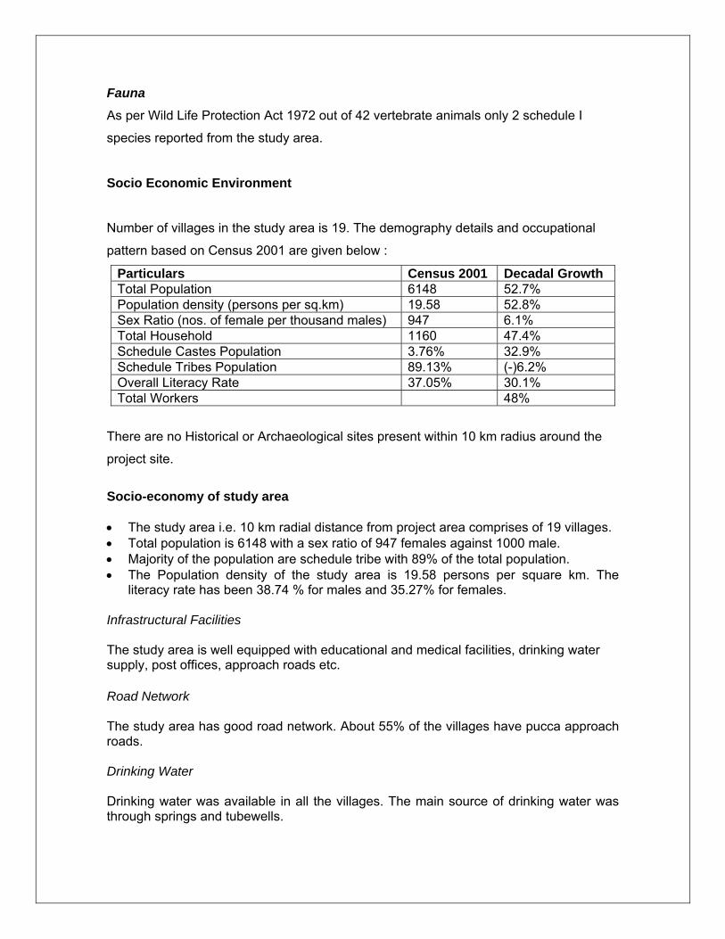
Fauna
As per Wild Life Protection Act 1972 out of 42 vertebrate animals only 2 schedule I
species reported from the study area.
Socio Economic Environment
Number of villages in the study area is 19. The demography details and occupational
pattern based on Census 2001 are given below :
Particulars Census 2001 Decadal Growth Total Population 6148 52.7% Population density (persons per sq.km) 19.58 52.8% Sex Ratio (nos. of female per thousand males) 947 6.1% Total Household 1160 47.4% Schedule Castes Population 3.76% 32.9% Schedule Tribes Population 89.13% (-)6.2% Overall Literacy Rate 37.05% 30.1% Total Workers 48%
There are no Historical or Archaeological sites present within 10 km radius around the
project site.
Socio-economy of study area • The study area i.e. 10 km radial distance from project area comprises of 19 villages. • Total population is 6148 with a sex ratio of 947 females against 1000 male. • Majority of the population are schedule tribe with 89% of the total population. • The Population density of the study area is 19.58 persons per square km. The
literacy rate has been 38.74 % for males and 35.27% for females. Infrastructural Facilities The study area is well equipped with educational and medical facilities, drinking water supply, post offices, approach roads etc. Road Network The study area has good road network. About 55% of the villages have pucca approach roads. Drinking Water Drinking water was available in all the villages. The main source of drinking water was through springs and tubewells.
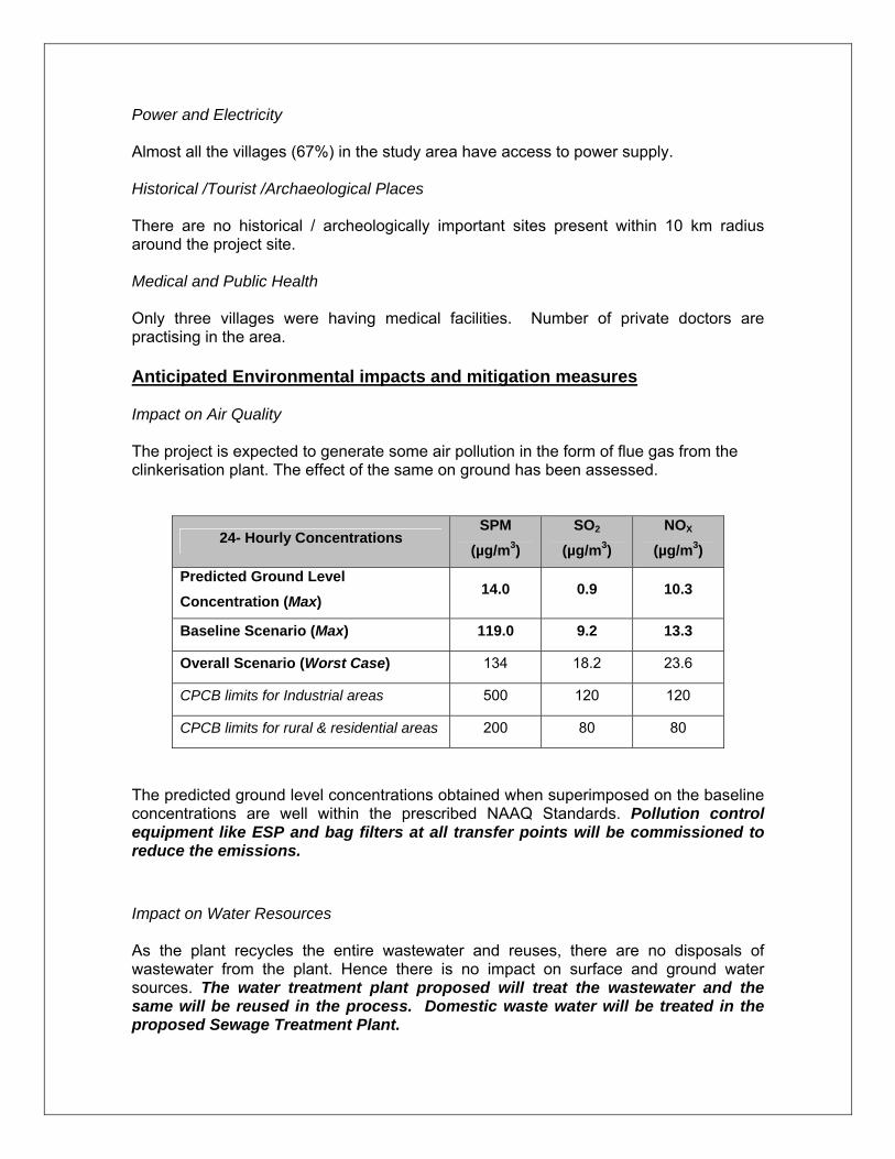
Power and Electricity Almost all the villages (67%) in the study area have access to power supply. Historical /Tourist /Archaeological Places There are no historical / archeologically important sites present within 10 km radius around the project site. Medical and Public Health Only three villages were having medical facilities. Number of private doctors are practising in the area. Anticipated Environmental impacts and mitigation measures Impact on Air Quality The project is expected to generate some air pollution in the form of flue gas from the clinkerisation plant. The effect of the same on ground has been assessed.
24- Hourly Concentrations SPM
(µg/m3) SO2
(µg/m3) NOX
(µg/m3)
Predicted Ground Level Concentration (Max)
14.0 0.9 10.3
Baseline Scenario (Max) 119.0 9.2 13.3
Overall Scenario (Worst Case) 134 18.2 23.6
CPCB limits for Industrial areas 500 120 120
CPCB limits for rural & residential areas 200 80 80
The predicted ground level concentrations obtained when superimposed on the baseline concentrations are well within the prescribed NAAQ Standards. Pollution control equipment like ESP and bag filters at all transfer points will be commissioned to reduce the emissions. Impact on Water Resources As the plant recycles the entire wastewater and reuses, there are no disposals of wastewater from the plant. Hence there is no impact on surface and ground water sources. The water treatment plant proposed will treat the wastewater and the same will be reused in the process. Domestic waste water will be treated in the proposed Sewage Treatment Plant.
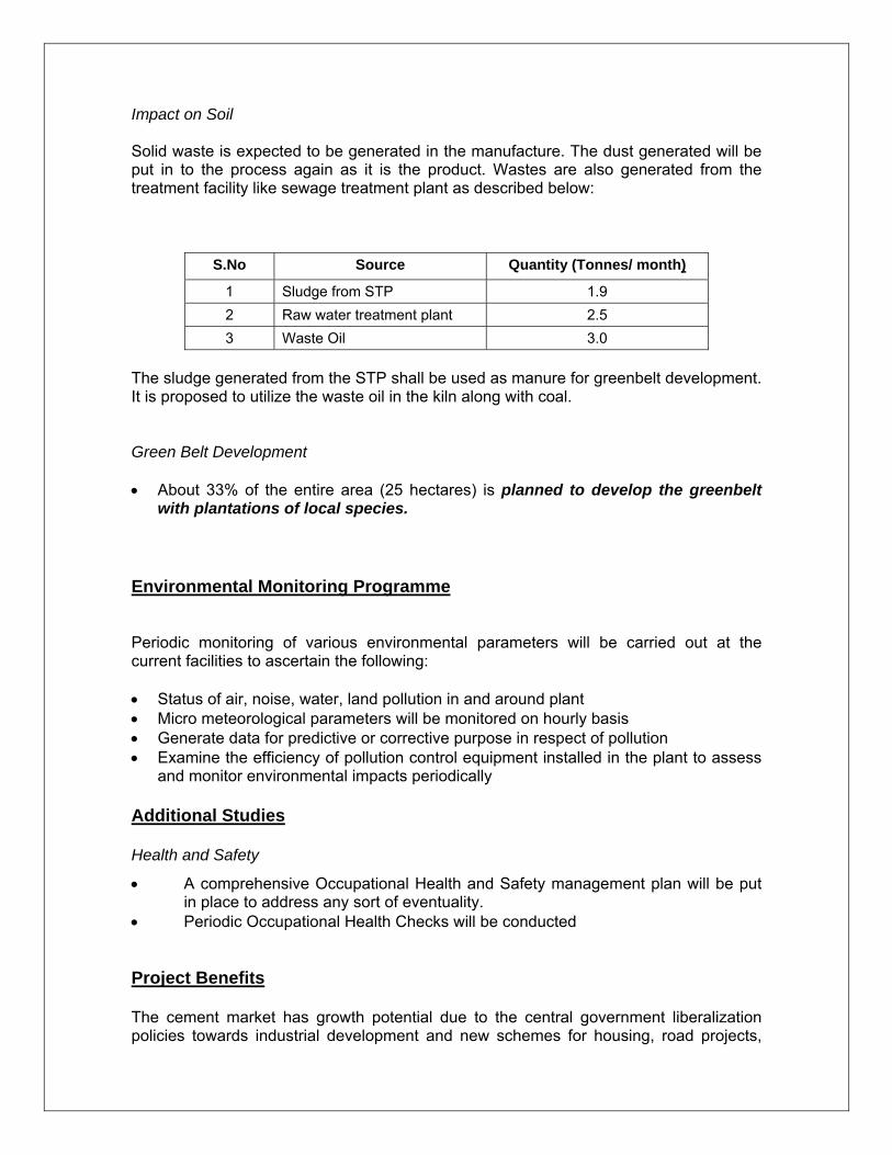
Impact on Soil Solid waste is expected to be generated in the manufacture. The dust generated will be put in to the process again as it is the product. Wastes are also generated from the treatment facility like sewage treatment plant as described below:
S.No Source Quantity (Tonnes/ month)
1 Sludge from STP 1.9 2 Raw water treatment plant 2.5 3 Waste Oil 3.0
The sludge generated from the STP shall be used as manure for greenbelt development. It is proposed to utilize the waste oil in the kiln along with coal. Green Belt Development • About 33% of the entire area (25 hectares) is planned to develop the greenbelt
with plantations of local species. Environmental Monitoring Programme Periodic monitoring of various environmental parameters will be carried out at the current facilities to ascertain the following: • Status of air, noise, water, land pollution in and around plant • Micro meteorological parameters will be monitored on hourly basis • Generate data for predictive or corrective purpose in respect of pollution • Examine the efficiency of pollution control equipment installed in the plant to assess
and monitor environmental impacts periodically Additional Studies Health and Safety
• A comprehensive Occupational Health and Safety management plan will be put in place to address any sort of eventuality.
• Periodic Occupational Health Checks will be conducted Project Benefits
The cement market has growth potential due to the central government liberalization policies towards industrial development and new schemes for housing, road projects,
hydel projects etc. Cement demand is anticipated to increase at an annual growth rate of 9 to 10%. Continuous demand for exports to South-East Asian countries along with the increased requirement of the domestic sector have led all the cement manufacturers in the country to plan for increased capacities. Enhancement of production capacity would add additional income to the nation. Socio-economic Benefits • A total of 407 personnel would be employed for the plant. The project creates many
opportunities for auxiliary industries, ships & establishments and indirect employment.
• The industrial development in the region facilitates the improvement of basic amenities like organized water supply, good roads, proper medical facilities and educational facilities.
Environmental Management Plan SCML is adopting corporate philosophy of eco-friendly development. The management firmly believes in the concept of sustainable industrial operations at all their facilities. To maintain ecological balance of the area, SCML has proposed to take adequate measures to mitigate all possible adverse impacts at its proposed project. An amount of Rs. 13.30 crores has been earmarked for pollution control and monitoring equipment. Conclusions • Rapid Environmental Impact Assessment study reveals that the impact due to the
proposed plant on Air environment, Water quality, Noise and Soil quality is minimal.
• It can be summarized that the industrial development at Lumshnong, P.O. Khliehriat, Jaintia Hills district, Meghalaya shall lead to a sustainable development of the region.

CONTENTS
Table of Contents
S.No Particulars Page No
1.0 Introduction 1 1.1 Need for the project-Demand Scenario 1 1.2 Present Proposal 1 1.3 Site selection criteria 1 1.4 Scope of the Study 3 1.4.1 Objectives 3 1.4.2 EIA Methodology 3 1.4.3 Environmental Focus Areas 4 2.0 Project Description 6 2.1 General Overview 6 2.2 Project Location 6 2.3 Detailed Process & Technology Description-Clinker Unit 9 2.3.1 Salient Features of the Cement Plant 9 2.3.2 Raw Materials Requirement 9 2.3.3 Manufacturing Process 11 2.3.4 System Details 12 2.3.4.1 Crushing 12 2.3.4.2 Storage 12 2.3.5 Pyro Process Section 14 2.3.6 Quality Control 15 2.4 Detailed Process & Technology Description-Power Plant 17 2.4.1 Fuel Sources and specifications 17 2.4.2 Power cycle configuration 18 2.4.3 Steam generators and auxiliaries 20 2.4.4 Utilities and services 23 2.4.5 Instrumentation and Control System 25 2.5 Infrastructure 27 2.6 Manpower 27 2.7 Township 28 2.8 Land Break up 28 3.0 Baseline Environment 31 3.1 Geography, Geomorphology & Geology of the Area 32 3.1.1 Topography 32 3.1.2 Geomorphology 32 3.1.3 Geology 33 3.1.4 Hydrogeology 34 3.1.5 Drainage pattern 35 3.1.6 Water Balance of study area 35 3.1.7 Climate 36 3.2 Baseline Environmental Results for Study Period (Summer ‘07) 37 3.2.1 Micro Meteorology 37 3.2.1.1 Temperature 37 3.2.1.2 Relative humidity 37 3.2.1.3 Rainfall 37 3.2.1.4 Wind speed 37 3.2.1.5 Wind direction 37 3.3 Ambient Air Quality (AAQ) 39 3.3.1 Observations of Ambient Air Quality 42 3.4 Noise Environment 43 3.4.1 Observations of Noise Levels Data 45 3.5 Water Environment 46 3.5.1 Observations of Water Quality Data 50 3.6 Soil Quality 50 3.6.1 Observations of Soil Quality Data 52
3.7 Biological Environment 53 3.7.1 Flora 53 3.7.2 Fauna 57 3.8 Socio Economic Environment 60 3.8.1 Cropping Pattern 63 3.9 Land Use Pattern 63 4.0 Environmental Impact Assessment 65 4.1 Prediction of Impacts 65 4.2 Assessment / Evaluation of Impacts 65 4.2.1 Environmental Setting 67 4.3 Impacts during construction phase 67 4.4 Impacts during operation phase 68 4.4.1 Air Pollution 69 4.4.2 Simulation Model for Prediction (ISCST) 73 4.4.3 Post Project Scenario 76 4.4.4 Impact of Vehicular Emissions 80 4.4.5 Impact on Water Quality 81 4.4.6 Impact on Ground Water 81 4.4.7 Impact on Noise Levels 82 4.4.8 Solid Waste Generation and Impact 82 4.4.9 Impact on Ecology 82 4.4.10 Demography and Socio-economics 83 4.4.11 Impact on Human Settlements 83 4.4.12 Impact on Health 83 5.0 Environmental Management Plan 84 5.1 Environmental Management Plan-Introduction 84 5.2 Environmental Management Plan during Construction Phase 84 5.2.1 Air Environment 84 5.2.2 Noise Environment 84 5.2.3 Water Environment 85 5.2.4 Land Environment 85 5.2.5 Socio-economic Environment 85 5.2.6 Safety and Health 85 5.3 Environmental Management Plan during Operations Phase 86 5.3.1 Air Environment 86 5.3.2 Noise Environment 87 5.3.3 Solid Waste Management 88 5.3.4 Water Resources/ Quality Management 89 5.3.5 Wastewater 89 5.3.6 Sewage treatment plant 89 5.3.7 Solid Waste 90 5.3.8 House keeping 91 5.3.9 Occupational Safety & Health 91 5.3.10 Measures to improve socio-economic conditions 92 5.3.11 Land use management 93 5.2.12 Greenbelt Development 93 5.4 Disaster Management Plan 96 5.4.1 Identification of Hazard & Preventive/Controlling Measures 97 5.4.2 Main Component of the On-Site Disaster Management Plan 100 5.4.3 Environmental Management Cell 103 5.4.4 Environmental Monitoring 104
List of Figures
S.No Particulars Page No
2.1 Project Location Map 6 2.2 Project Site Layout Plan 7
2.3 Project Site Layout Plan for Power plant 8 3.1 Geological Map of study area 33 3.2 Hydrogeomorphological map of study area
32
3.3 Drainage Pattern of the Study Area 35 3.4 24 Hrs. Wind rose Diagram 38 3.5 00-08 Hrs. Wind rose Diagram 38 3.6 08-16 Hrs. Wind rose Diagram 38 3.7 16-24 Hrs. Wind rose Diagram 38 3.8 Map Showing Air Quality Stations 41 3.9 Map showing Noise Monitoring Locations 44
3.10 Map showing Water Quality Monitoring Locations 47 3.11 Map showing Soil Sampling Locations 51 3.12 Land Use Pattern of the study area 64 4.1 Predicted 24- Hourly Average GLCs of SPM (ug/m3) 77 4.2 Predicted 24-Hourly Average GLCs of SO2 (ug/m3) 78 4.3 Predicted 24-Hourly Average GLCs of NOx (ug/m3) 79
List of Tables
S.No Particulars Page No
1.1 Salient features of project 2 2.1 Requirement of raw materials 9 2.2 Quality of raw material 10 2.3 Analysis of fuels 10 2.4 List of major equipments and storages recommended 16 2.5 Meghalaya Coal Analysis Results 18 3.1 Environmental Attributes & Frequency of Monitoring 39 3.2 Methodology of AAQ Sampling and analysis 40 3.3 AAQ Sampling Location Details 40 3.4 AAQ Summary during Summer Season (Mar’07–May’07) 42 3.5 Noise Monitoring Locations 43 3.6 Equivalent Noise Levels in the Study Area (10 km radius) 45 3.7 Water sampling locations 46 3.8 Summary of Water Quality Analysis Results 48 3.9 Summary of Water Quality Analysis Results 49
3.10 Location of Soil Sampling Stations 50 3.11 Soil Quality Analysis Results 52 3.12 Tree Species Available in the Study Area 53 3.13 Shrub/Herbs Species Available in the Study Area 55 3.14 Climbers/Epiphytes Species Available in the Study Area 57 3.15 Vertebrates Available in the Study Area 57 3.16 Invertebrates Available in the Study Area 59 3.17 Classification of the Villages Based on Population Size 60 3.18 Demographic Details of the Study Area 61 3.19 Occupational Pattern of the Study Area 61 3.20 Land Use Pattern of the Study Area 63 4.1 Environmental Impact Matrix 66 4.2 Nature of Impacts during Construction Phase 68 4.3 Nature of Impacts during Operation Phase 68 4.4 Stack & Emission Details 75 4.5 Post Project Scenario 76 4.6 Estimate of Trucks for Transport 80 4.7 Emissions through transportation 80 4.8 Water Requirements 81 4.9 Noise Levels at Different Sources 82

5.1 Characteristics of effluents 90 5.2 Details Solid Waste Generation 90 5.3 Land Use in the project site 93 5.4 Species Preferred to be planted 94 5.5 Details of Flammable Materials 96 5.6 Details of Storage of Petroleum Products 96 5.7 Proposed Environmental Monitoring Schedule 104 5.8 Comprehensive management plan for risk analysis and possible hazards 106 5.9 Annexure 114

INTRODUCTION
Star Cement Meghalaya Limited, Meghalaya
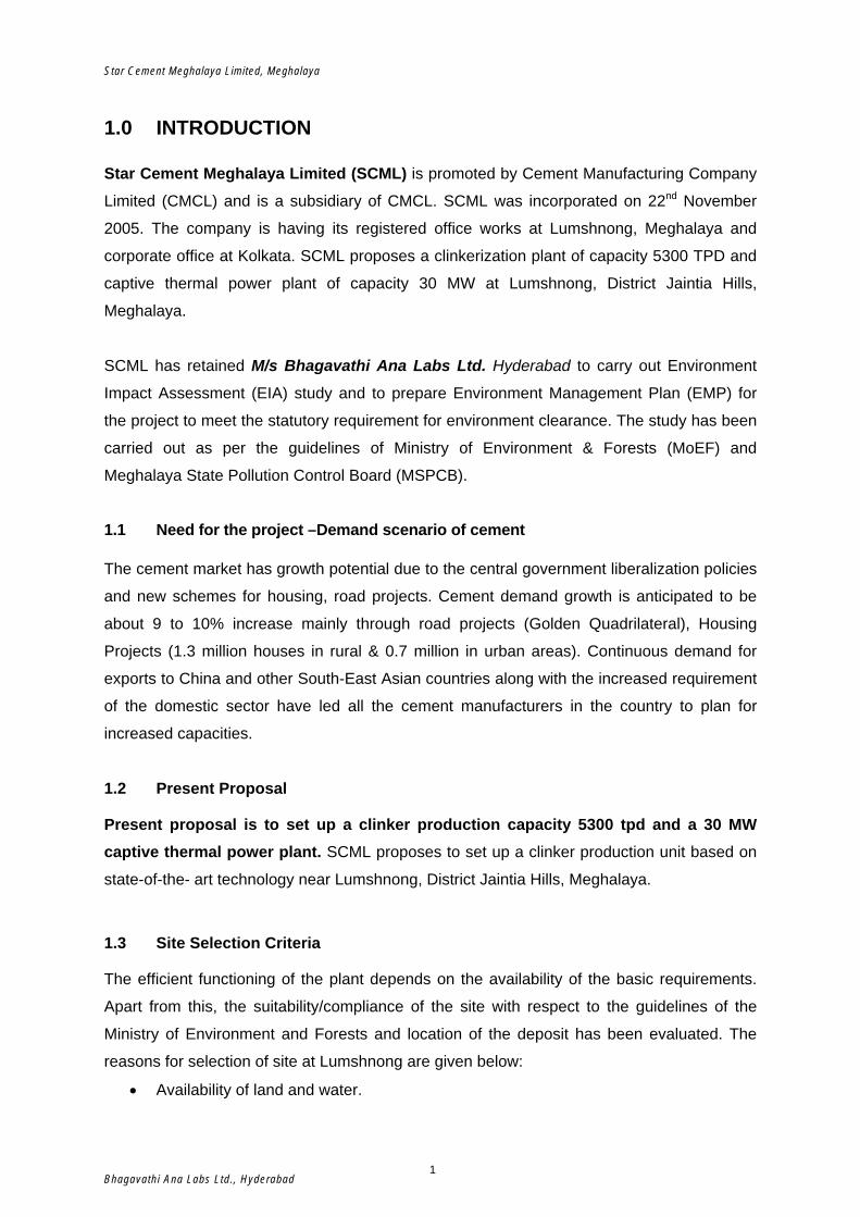
1.0 INTRODUCTION Star Cement Meghalaya Limited (SCML) is promoted by Cement Manufacturing Company
Limited (CMCL) and is a subsidiary of CMCL. SCML was incorporated on 22nd November
2005. The company is having its registered office works at Lumshnong, Meghalaya and
corporate office at Kolkata. SCML proposes a clinkerization plant of capacity 5300 TPD and
captive thermal power plant of capacity 30 MW at Lumshnong, District Jaintia Hills,
Meghalaya.
SCML has retained M/s Bhagavathi Ana Labs Ltd. Hyderabad to carry out Environment
Impact Assessment (EIA) study and to prepare Environment Management Plan (EMP) for
the project to meet the statutory requirement for environment clearance. The study has been
carried out as per the guidelines of Ministry of Environment & Forests (MoEF) and
Meghalaya State Pollution Control Board (MSPCB).
1.1 Need for the project –Demand scenario of cement
The cement market has growth potential due to the central government liberalization policies
and new schemes for housing, road projects. Cement demand growth is anticipated to be
about 9 to 10% increase mainly through road projects (Golden Quadrilateral), Housing
Projects (1.3 million houses in rural & 0.7 million in urban areas). Continuous demand for
exports to China and other South-East Asian countries along with the increased requirement
of the domestic sector have led all the cement manufacturers in the country to plan for
increased capacities.
1.2 Present Proposal
Present proposal is to set up a clinker production capacity 5300 tpd and a 30 MW captive thermal power plant. SCML proposes to set up a clinker production unit based on
state-of-the- art technology near Lumshnong, District Jaintia Hills, Meghalaya.
1.3 Site Selection Criteria
The efficient functioning of the plant depends on the availability of the basic requirements.
Apart from this, the suitability/compliance of the site with respect to the guidelines of the
Ministry of Environment and Forests and location of the deposit has been evaluated. The
reasons for selection of site at Lumshnong are given below:
• Availability of land and water.
Bhagavathi Ana Labs Ltd., Hyderabad 1
Star Cement Meghalaya Limited, Meghalaya
• Compliance of the site with the siting guidelines of MOEF.
• Proximity of the limestone deposit.
• Availability of road to facilitate transportation of equipment, raw material and product.
• Availability of labour force during construction and operation phase.
• Accessibility of the site from environmental aspects.
• No national park or wild life sanctuary exists within 10 km of the plant.
• There are no sensitive places of archaeological, historical, cultural, and religious or
tourist importance within 10 km of the plant.
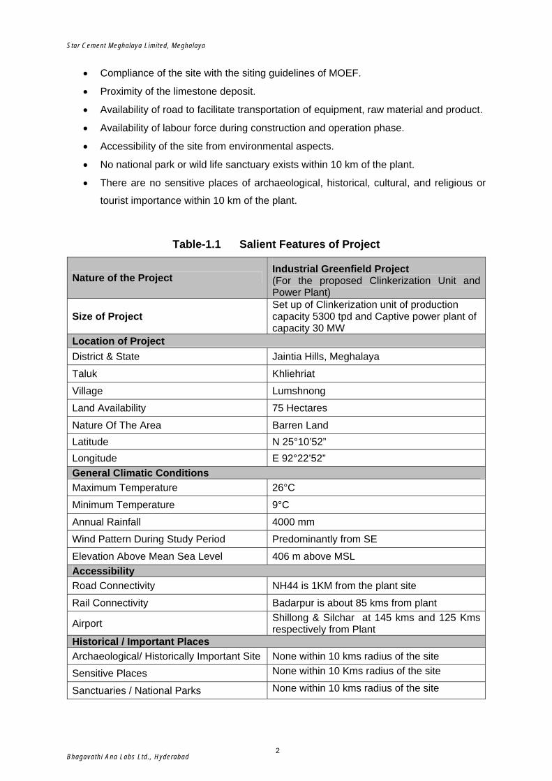
Table-1.1 Salient Features of Project
Nature of the Project Industrial Greenfield Project (For the proposed Clinkerization Unit and Power Plant)
Size of Project Set up of Clinkerization unit of production capacity 5300 tpd and Captive power plant of capacity 30 MW
Location of Project District & State Jaintia Hills, Meghalaya
Taluk Khliehriat
Village Lumshnong
Land Availability 75 Hectares
Nature Of The Area Barren Land Latitude N 25°10’52” Longitude E 92°22’52” General Climatic Conditions Maximum Temperature 26°C
Minimum Temperature 9°C
Annual Rainfall 4000 mm
Wind Pattern During Study Period Predominantly from SE
Elevation Above Mean Sea Level 406 m above MSL Accessibility Road Connectivity NH44 is 1KM from the plant site
Rail Connectivity Badarpur is about 85 kms from plant
Airport Shillong & Silchar at 145 kms and 125 Kms respectively from Plant
Historical / Important Places Archaeological/ Historically Important Site None within 10 kms radius of the site
Sensitive Places None within 10 Kms radius of the site
Sanctuaries / National Parks None within 10 kms radius of the site
Bhagavathi Ana Labs Ltd., Hyderabad 2
Star Cement Meghalaya Limited, Meghalaya
1.4 Scope of the Study The scope of the study includes detailed characterization of various environmental
components like air, noise, water, land and socio-economics within an area of 10 km radius
around the proposed project site.
1.4.1 Objectives
The objectives set for carrying out this EIA study were based upon the
requirements that fulfill the new Environment Impact Assessment Notification 2006
under the aegis of MoEF and its various amendments. These objectives are
described hereunder,
• Literature review that includes identification of relevant data and articles from
various publications, various government agencies and other sources;
• Collection of available secondary data
• Environmental monitoring so as to establish the baseline environmental status of
the study area
• Identify various existing pollution loads due to industrial and domestic activities in
the ambient zone
• Prediction of impacts on environmental attributes
• Evaluate the predicted impacts on the various environmental attributes in the
study area by using scientifically developed and widely accepted Environmental
Impact Assessment (EIA) Methodologies
• Preparation of an Environmental Management Plan (EMP) outlining the
measures for improving the environmental quality
• Identify critical environmental attributes required to be monitored
1.4.2 EIA Methodology
Environmental Impact Assessment study has been conducted within an area of 10 km
radius around the project area. The various steps involved in the study for a particular
project are divided into three following phases.
• Identification of significant environmental parameters and assessing the status
within the impact zone
• Prediction of Impacts envisaged due to proposed scheme on various
environmental parameters
Bhagavathi Ana Labs Ltd., Hyderabad 3
Star Cement Meghalaya Limited, Meghalaya
• Evaluation of impacts after superimposing the predicted scenario over the
baseline scenario to prepare Environmental Management Plan
Accordingly, field studies were carried out during the study period to establish the existing
conditions. To determine the magnitude of significant potential impacts and to ensure that
the environmental considerations are given adequate weightage, subsequently, a
preliminary environmental screening was carried out. The environmental screening was
based on the available secondary data supplemented by regular field visits. During
screening, significant environmental issues were examined for all the alternatives. Primary
and secondary data were collected to describe the existing environmental set-up. The
methodology adopted is presented in the form of a flow chart. Keeping in view the activities
envisaged and size of the project activities, the work carried out is briefly reported below and
has been described in detail in the subsequent sections.
1.4.3 Environmental Focus Areas
A) Air Environment
The prevailing ambient air quality status of the study region was assessed through a network
of 8 ambient air-monitoring stations during pre-monsoon season (2007). Different pollution
parameters viz. Suspended Particulate Matter (SPM), Respirable Suspended Particulate
Matter (RSPM), Sulphur-di-oxide (SO2), Oxides of nitrogen (NOX) and HC & CO. were
identified for representing the baseline status of ambient air quality within the study region.
High Volume Samplers and Respirable Dust Samplers have been used for continuous
monitoring of these parameters
Micro-meteorological parameters like wind speed & direction were continuously recorded
using an automatic weather station during study period. The recorded data were used to
determine predominant meteorological conditions, which are useful in characterizing the
baseline air quality status and in prediction of impacts on air environment.
B) Noise Environment
Noise is generated by many activities associated with the plant activities. Noise pollution
survey has been carried out in the study area to assess the impacts of the plant activities.
Noise level surveys were carried out in and around the project study area. Noise levels (A-
weighted) were recorded using a Portable Noise Level Meter.
Bhagavathi Ana Labs Ltd., Hyderabad 4
Star Cement Meghalaya Limited, Meghalaya
C) Water Environment
There are many perennial nallahs and springs scattered in the study area charged with rain
water and aquifers. Primary and secondary information on water resources (ground/surface)
was collected. The parameters of prime importance selected under physico-chemical
characteristics were estimated to describe the baseline environmental status of the water
resources during the pre-monsoon ( January to March, 07).
D) Land Environment
Soil samples were collected from different locations within the project study area during the
study period and were analyzed for various physico-chemical parameters.
E) Socio-Economic Environment
Socio-economic information such as, demographic pattern, population density, literacy
levels, gender ratio, educational facilities, agriculture, income, medical facilities, etc., was
collected through basic surveys and from few reliable secondary sources. The same has
been analyzed and presented in the subsequent chapters.
Bhagavathi Ana Labs Ltd., Hyderabad 5

PROJECT DESCRIPTION
Star Cement Meghalaya Limited, Meghalaya
2.0 PROJECT DESCRIPTION 2.1 General Overview The State of Meghalaya is located between latitudes of 25º00' and 26º10' N and longitudes
of 89º45' and 92º47'E with an altitude ranging from 50-1961 meters above Main Sea Level
(MSL) and covers 22.4 lakhs ha (22,429 Sq.kms). The State is bounded by Assam in the
North, East and West and Bangladesh in the South and West.
Agriculture is the mainstay of the people of the State. About 85 percent of the population of
the State live in rural areas and depend on agriculture for their livelihood. Of the total
geographical area, about 13 percent is under cultivation. Efforts are being made to increase
irrigation potential of the State and bring more area under cultivation. It is in the primitive
stage of shifting cultivation in major parts of the State. Shifting Cultivation locally named as
‘Jhuming’ is practiced extensively on the hill-slopes in the Garo Hills and part of the Khasi
and Jaintia Hills Districts. The soil and climatic condition of the State is suitable for growing
different types of agricultural crops from cereals to fruits in both tropical and temperate
climatic environment occurring on different altitudes.
Meghalaya is basically an Agricultural State with about 80% of its total population depending
entirely on Agriculture for their livelihood. In Meghalaya, summer is for a period of about 5
months, from May to September, with torrential rains caused by the South West Monsoon.
Rainfall varies from place to place and from altitude to altitude. The amount of rainfall over
Cherrapunjee and Mawsynram is quite heavy.
Only 50% of the villages in Meghalaya get electricity. Most people depend upon their land for
livelihood. Recently, new industrial units were set up in view of the positive industrial policy
of the Meghalaya Government
2.2 Project Location
The proposed project is situated at Lumshnong, P.O. Khliehriat, Jaintia Hills district,
Meghalaya. The longitude and latitude of the project site are E 92°22’52” and N 25°10’52”.
The project would be in the premises of the existing plant with a total area of 35 Hectares.
This area comprises of Operational area, green-belt area, open area designated for different
purposes. Necessary approach roads and raw material storage areas is also earmarked.
Project Location Map is presented as Fig-2.1.
Bhagavathi Ana Labs Ltd., Hyderabad 9
Star Cement Meghalaya Limited, Meghalaya
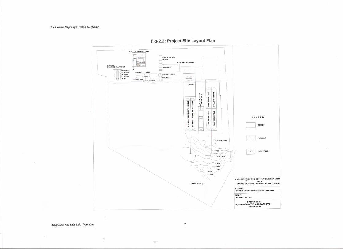
Fig-2.2: Project Site Layout Plan
CLINKER
LOADING PLAT FORM
mUN'RUNT
CLINKER
HOPPER
CLINKER
J SILO
~RAW MIll8AGtEHOUSE
COOLER KILN
I I I I U (1JfENDING SILOT.A.DUCT I
COO~R ESP D COAL MIllCCT BUILDING
==D
~-IlNALlAH
CLIENT:STAR CEMENT MEGHALAYA LIMITED
PROJECT,S~')O TPD C;'~~NT CLINKER UNlll30 MW CAPTIVE THERMAL POWER PLAN
CHECK POST 0
LEGEND
B CONTOURS
D NAlLAH
DROAD
;TrTLE:PLANT LAYOUT
PREPARED BY
Mjs.BHAGAVATHI ANA LABS lTDHYDERABAD
Bhagavathi Ana Labs Ltd., Hyderabad 7
Star Cement Meghalaya Limited, Meghalaya
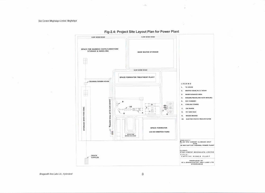
Fig-2.4: Project Site Layout Plan for Power Plant
••".""M· -=ll"'" ". ""~ '"","'"'=" 1STORAGE & HAN DLING
6.0M WIDE ROAD
RAW WATER STORAGE
SPACE FORWATER TREATMENT PLANT
oJ0(ou'"ou.ow:z:IIIwCl0('"otIII
'CRUSHER/SCREEN HOUSE
"~,"!
~~~0(
~l:l.•
.8
6.0M WIDE ROAD
~;~l~~J
LEGEND
1.
TG HOUSE
2.
SWITCH GEAR/M.C.C ROOM
3.
MAINTAINANCE AREA
4.
BOIlER(TRAVELING GATE BOILER)
5.
RCC CHIMNEY
~
6.COOLING TOWER
7.
cw PUMPS
7 I8.
FLY ASH SILO
6 ..WEIGH BRIDGE
10.
ELECTRO STATIC PRECIPITATOR
SPACE FORWATER
132 KV SWITCH YARD
PROJECT:
i~3"JO TPD CEMAE~~ CLINKER UNIT30 MW CAPTIVE THERMAL POWER PLANT
Bhagavathi Ana Labs Ltd., Hyderabad
~RUCKTIPPLER
[)
CLIENT:STAR CEMENT MEGHALAYA LIMITED
TIT L E :CAPTIVE POWER PLANT
PREPARED BY
M/s.BHAGAVATHI ANA LABS LTDHYDERABAD
Star Cement Meghalaya Limited, Meghalaya
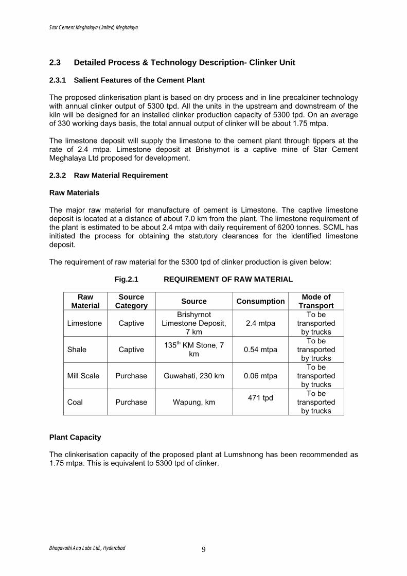
2.3 Detailed Process & Technology Description- Clinker Unit 2.3.1 Salient Features of the Cement Plant The proposed clinkerisation plant is based on dry process and in line precalciner technology with annual clinker output of 5300 tpd. All the units in the upstream and downstream of the kiln will be designed for an installed clinker production capacity of 5300 tpd. On an average of 330 working days basis, the total annual output of clinker will be about 1.75 mtpa. The limestone deposit will supply the limestone to the cement plant through tippers at the rate of 2.4 mtpa. Limestone deposit at Brishyrnot is a captive mine of Star Cement Meghalaya Ltd proposed for development. 2.3.2 Raw Material Requirement Raw Materials The major raw material for manufacture of cement is Limestone. The captive limestone deposit is located at a distance of about 7.0 km from the plant. The limestone requirement of the plant is estimated to be about 2.4 mtpa with daily requirement of 6200 tonnes. SCML has initiated the process for obtaining the statutory clearances for the identified limestone deposit. The requirement of raw material for the 5300 tpd of clinker production is given below:
Fig.2.1 REQUIREMENT OF RAW MATERIAL
Raw
Material Source
Category Source Consumption Mode of Transport
Limestone Captive Brishyrnot
Limestone Deposit, 7 km
2.4 mtpa To be
transported by trucks
Shale Captive 135th KM Stone, 7 km 0.54 mtpa
To be transported by trucks
Mill Scale Purchase Guwahati, 230 km 0.06 mtpa To be
transported by trucks
Coal Purchase Wapung, km 471 tpd
To be transported by trucks
Plant Capacity The clinkerisation capacity of the proposed plant at Lumshnong has been recommended as 1.75 mtpa. This is equivalent to 5300 tpd of clinker.
Bhagavathi Ana Labs Ltd., Hyderabad 9
Star Cement Meghalaya Limited, Meghalaya
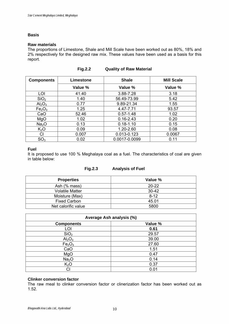
Basis Raw materials The proportions of Limestone, Shale and Mill Scale have been worked out as 80%, 18% and 2% respectively for the designed raw mix. These values have been used as a basis for this report.
Fig.2.2 Quality of Raw Material
Limestone Shale Mill Scale Components
Value % Value % Value % LOI 41.40 3.88-7.28 3.18 SiO2 1.40 56.49-73.99 5.42 Al2O3 0.77 9.89-21.34 1.55 Fe2O3 1.25 4.47-7.71 93.57 CaO 52.46 0.57-1.48 1.02 MgO 1.02 0.16-2.43 0.20 Na2O 0.13 0.18-1.10 0.15 K2O 0.09 1.20-2.60 0.08 Cl 0.007 0.013-0.123 0.0067
SO3 0.02 0.0017-0.0099 0.11 Fuel It is proposed to use 100 % Meghalaya coal as a fuel. The characteristics of coal are given in table below:
Fig.2.3 Analysis of Fuel
Properties Value %
Ash (% mass) 20-22 Volatile Matter 30-42 Moisture (Max) 8-12 Fixed Carbon 45.01
Net calorific value 5800
Average Ash analysis (%) Components Value %
LOI 0.61 SiO2 29.57 Al2O3 39.00 Fe2O3 27.60 CaO 1.51 MgO 0.47 Na2O 0.14 K2O 0.37 Cl 0.01
Clinker conversion factor The raw meal to clinker conversion factor or clinerization factor has been worked out as 1.52.
Bhagavathi Ana Labs Ltd., Hyderabad 10
Star Cement Meghalaya Limited, Meghalaya
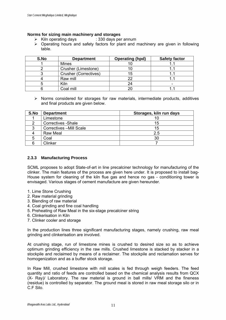
Norms for sizing main machinery and storages
Kiln operating days : 330 days per annum Operating hours and safety factors for plant and machinery are given in following
table.
S.No Department Operating (hpd) Safety factor 1 Mines 10 1.1 2 Crusher (Limestone) 10 1.1 3 Crusher (Correctives) 15 1.1 4 Raw mill 22 1.1 5 Kiln 24 - 6 Coal mill 20 1.1
Norms considered for storages for raw materials, intermediate products, additives
and final products are given below. S.No Department Storages, kiln run days
1 Limestone 10 2 Correctives -Shale 15 3 Correctives –Mill Scale 15 4 Raw Meal 2.5 5 Coal 30 6 Clinker 7
2.3.3 Manufacturing Process SCML proposes to adopt State-of-art in line precalciner technology for manufacturing of the clinker. The main features of the process are given here under. It is proposed to install bag-House system for cleaning of the kiln flue gas and hence no gas - conditioning tower is envisaged. Various stages of cement manufacture are given hereunder. 1. Lime Stone Crushing 2. Raw material grinding 3. Blending of raw material 4. Coal grinding and fine coal handling 5. Preheating of Raw Meal in the six-stage precalciner string 6. Clinkerisation in Kiln 7. Clinker cooler and storage In the production lines three significant manufacturing stages, namely crushing, raw meal grinding and clinkerisation are involved. At crushing stage, run of limestone mines is crushed to desired size so as to achieve optimum grinding efficiency in the raw mills. Crushed limestone is stacked by stacker in a stockpile and reclaimed by means of a reclaimer. The stockpile and reclamation serves for homogenization and as a buffer stock storage. In Raw Mill, crushed limestone with mill scales is fed through weigh feeders. The feed quantity and ratio of feeds are controlled based on the chemical analysis results from QCX (X- Ray)/ Laboratory. The raw material is ground in ball mills/ VRM and the fineness (residue) is controlled by separator. The ground meal is stored in raw meal storage silo or in C.F Silo.
Bhagavathi Ana Labs Ltd., Hyderabad 11
Star Cement Meghalaya Limited, Meghalaya
Clinkerisation is the heart of cement manufacturing process, where the raw meal fed to the preheater at controlled rate through electronic weigh-feeder and or solid flow meters. The feed enters the kiln through cyclones and precalciner and the fuel is fired at the kiln outlet end and precalciner. The counter current of hot gases against the material flow right from preheater top stage to kiln outlet converts raw mix to clinker by pyroprocessing stages like calcinations and clinkerisation. The clinker is cooled in air – quenched cooler. Clinker is transported to clinker yard for storage. 2.3.4 System Details 2.3.4.1 Crushing Limestone crusher It has been recommended to install a single/double rotor crusher for limestone at the plant site. The ROM limestone shall be carried by tippers from quarry to plant site. The capacity of the crusher will be 1100 tph. For feeding the ROM material to the crusher at plant, a crusher feed hopper of mass flow design may be installed before the crusher. Material from the feed hopper discharge to the crusher is envisaged by a heavy duty Apron conveyor. The typical feed lump size to the crusher will be maximum 1,200 mm edge length. The size distribution of crushed material will be controlled to achieve 100 % passing 75 mm sieve with the maximum product size as 100 mm. Suitable belt conveyor is proposed from crusher to stacker belt at plant site. Correctives crusher It has been recommended to install a single/double rotor crusher for correctives at the plant site. The correctives shall be carried by tippers from quarry to plant site. The capacity of the crusher will be 190 tph. For feeding the correctives to the crusher at plant, a crusher feed hopper of mass flow design may be installed before the crusher. Material from the feed hopper discharge to the crusher is envisaged by a heavy duty Apron conveyor. 2.3.4.2 Storage Limestone storage Two nos of Chevron type, longitudinal stockpiles of 2 x 35,000 t capacity have been proposed for storage and homogenization of the crushed limestone. The storage capacity of limestone has been considered for 10 days consumption. The crushed limestone received from the crusher shall be stacked with the help of stacker of capacity 1,200 tph. Correctives storage Considering the wide variation in the quality of shale, two nos of Chevron type, longitudinal stockpiles of 2 x 1400 t capacity have been proposed for storage and homogenization of the crushed shale and a 2500 t stockpile for mill scale. The storage capacity of shale and mill scale have been considered for 15 days consumption. The crushed material received from the crusher shall be stacked with the help of single boom stacker of capacity 225 tph. For extraction of shale a bridge type reclaimer of capacity 185 tph has been considered.
Bhagavathi Ana Labs Ltd., Hyderabad 12
Star Cement Meghalaya Limited, Meghalaya
Limestone pre-blending Two nos. Chevron type, longitudinal mix stockpiles have been proposed for storage and homogenization of crushed limestone at the plant site. A stacker shall be installed for limestone stacking. For material extraction, a bridge type reclaimer has been considered. While stacking of limestone in one mix pile, the material reclaiming will be done from the other. Reclaimed material shall be transported to the mix material hoppers in the raw mill department through a series of belt conveyors. Raw material drying and grinding For raw material drying & grinding, the following options have been considered at the plant site. ¢ Closed circuit ball mill (CCBM) ¢ Closed circuit roller press (CCRP) ¢ Vertical roller mill (VRM) In view of the various pros and cons for different alternatives (like high drying capacity, low energy consumption, financial considerations, etc.), the installation of a VRM has been recommended. The VRM shall be equipped with a new generation, high efficiency separator. An external reject recirculation system will be provided in VRM circuit for energy saving. Hot gas from the PH fan exit shall be used for drying the moisture content of the raw materials. For situations like start up, and when the kiln stops but the raw meal has to be operated, a suitably designed hot air generator (HAG) may be installed. Mill product shall have maximum 0.5 % moisture. For mill feeding, steel hoppers of mass flow design, shall be installed. An Apron feeder and weigh feeder shall be installed below each hopper for the weighing and proportioning. Mill vent gas shall be dedusted in twin cyclones. Exit gas from the cyclones shall be transported to the Bag house through the raw mill fan. Gas from the raw mill fan along with the gas from pH fan exit shall be dedusted in the Bag house. Product collected at the bottom of the cyclones and bag house shall be transported to the raw meal storage silo through a set of chain conveyors, bucket elevator and air slides. Material collected from the Bag house bottom shall be transported to the kiln feed bin when kiln operates and to raw meal silo when kiln stops but raw mill operates. The bag house will be designed to meet the requirements of the environmental norms. A separate bag filter will be provided for dedusting of the feed hoppers and mill auxiliaries. Raw material blending and kiln feed Blending will be performed to minimize the variations in chemistry of raw meal. For homogenization of the raw meal, it is recommended to provide a continuous, controlled flow type blending silo with design blending ratio as minimum 7. The proposed capacity of the raw meal silo will be 22,000 t. Provision will be made for the recirculation of material from silo discharge to silo feeding. A kiln feed system, comprising of a steel bin shall be installed beneath the blending silo. The system shall use gravimetric feed control by solid flow meters. A system having bucket elevators and air slides has been considered for feeding the material to preheater (PH).
Bhagavathi Ana Labs Ltd., Hyderabad 13
Star Cement Meghalaya Limited, Meghalaya
Coal crushing and storage Coal received at site shall be unloaded by truck tippler into a receiving hopper and shall be transported to the coal crusher through an apron feeder & a set of belt conveyors. A roll crusher shall be installed for crushing the as received coal. Crushed coal will be stacked in the covered storage through stacker and belt conveyors having water spray system to prevent the dust nuisance. From the storage, coal will be reclaimed to its hopper in coal mill section through a series of belt conveyors. Coal drying and grinding In view of high drying capacity and low energy consumption, a VRM of capacity 35 tph shall be installed for coal drying & grinding at the proposed plant site. The VRM shall be equipped with a new generation, high efficiency separator. For coal drying, hot gas from the PH exit will be supplied through a booster fan to the VRM after dedusting it in a cyclone. Dust laden mill vent gas shall be transported to the coal mill bag filter. Fine coal product collected at the bottom of the bag filter shall be transported to the respective fuel bins through screw conveyors. For fuels to be fired, 2 nos. bins and 3 nos. F.K Pump shall be provided. For the situations like start- up phase and when kiln stops but the coal mill has to be operated, a suitably designed HAG may be installed. HAG will be common for raw mill as well as coal mill. Fine coal will have about 1 % moisture. 2.3.5 Pyro process section Kiln, PH & Precalciner (PC) A dry-process kiln installation has been envisaged. The PH may have 5 or 6 stage cyclones. With higher number of cyclone stages in the PH results in lower specific heat consumption and lower PH exit gas temperature. On the other hand, the total pressure drop across the PH increases and hence, the specific power consumption of the PH fan increases with increasing the number of PH stages. As such, there is no appreciable moisture content in the raw materials and fuel. Thus, there is no requirement of higher PH exit gas temperature. In view of this and economy in the specific heat consumption, it has been recommended to install twin string, 6 stage PH having new generation, high efficiency cyclones with low-pressure drop. The overall separation efficiency of the PH will be minimum 92 %. A low NOx, In-line calciner is envisaged to be installed. About 40 % fuel shall be fired in kiln and the balance 60 % fuel shall be fired in PC. The kiln feed material from storage silo shall be introduced into the PH by means of a system having bucket elevator and air slides. The material will be preheated in the PH before entering the PC. Fuel firing in the PC shall be controlled to achieve about 95 % calcination of the material at its discharge. A separate tertiary air duct (TAD) will be installed to transport the preheated air from the clinker cooler to the PC. For each PH string, a high efficiency, suitably designed PH fan will be installed for handling the gas from PH exit. Kiln burner A modern, low NOx, multi - channel type burner with low primary air consumption shall be installed for coal firing in the kiln. Clinker cooler A new generation, high heat recuperation efficiency (minimum 75 %) clinker cooler shall be installed. A cooler ESP and a cooler ESP fan shall be installed for dedusting and venting of the cooler exhaust gas. For a situation when the cooler exit gas temperature exceeds a certain value of say 300°C, the provision will be made for gas cooling by water spray in duct between cooler exit and cooler ESP.
Bhagavathi Ana Labs Ltd., Hyderabad 14
Star Cement Meghalaya Limited, Meghalaya
Specific heat consumption For the suitably designed pyro processing system as recommended, the specific heat consumption is generally specified as about 720-730 Kcal/ kg clinker. However, the expected average specific heat consumption will be more than this value due to operational abnormalities like variations in the quality of kiln feed material and fuel, variations in feed rate, sudden dislodging of coating, etc. Expected average specific heat consumption will be about 740 Kcal/ kg clinker, which is the value considered in this report. Clinker transport & storage Clinker from the clinker cooler discharge shall be transported by deep pan conveyor (DPC) to the clinker silo of capacity 32,000 t made of RCC structure at the proposed plant site. An off spec silo, of about 1,000 t has also been considered for under burnt clinker at the plant site. 2.3.6 Quality control The quality control department at the proposed plant shall have the following facilities: - For Chemical Analysis
X-ray fluorescence (XRF)
X-ray fluorescence can be used for on-line proportioning & control of raw mix preparation. Generally, 5-13 elemental oxides can be analyzed. Provisions for installation of Auto sample collection, Auto sample preparation employing robotic
Technology & its pneumatic transportation to laboratory are envisaged.
X-ray diffractometer (XRD) It can be used for estimation of phases (C3S, C2S, C3A, C4AF) & free lime in clinker.
Conventional chemical analysis equipment.
- For Physical Analysis Facilities for testing the physical properties like sieve analysis, setting time, soundness, fineness, CCS, grind ability, moisture content, lime reactivity and drying shrinkage, etc. - Particle Size Distribution (PSD) For determining the PSD of the raw mix, kiln feed material, PH return dust, clinker, cements, etc. a laser diffraction type PSD analyzer may be installed having typical particle size range of 0.3 mm – 400 micron. - Quality Control PlanTo produce good quality cement, it is imperative that sampling & testing of various raw materials, fuels, in -process materials and the final product is carried out regularly at the required intervals for taking corrective action timely. To ensure consistent product quality and to permit the trouble free and cost effective operation, the quality control plan for sampling & testing of various raw materials, in-process materials and the final product is suggested. While proposing the methods and procedures for quality control, the following aspects have been taken into account:
Requirements and norms, particularly in cement testing. Corrective measures to be undertaken as quickly as possible in the process
operation.
Bhagavathi Ana Labs Ltd., Hyderabad 15
Star Cement Meghalaya Limited, Meghalaya
Desired degree of automation. Available raw materials and process equipment.
Facilities and equipment envisaged for quality control of raw materials and finished products for the proposed plant are as follows: Raw mix preparation - Raw material control in quarry
- Raw material control before pre -blending - Raw meal control after raw mill
Pyro - processing - Kiln feed - Fuel - Clinker
Laboratory The laboratory will be accommodated in the Central Control Room (CCR) building at the proposed plant site. The laboratory shall have the provision of chemical and physical testing facilities for raw materials, clinker etc.
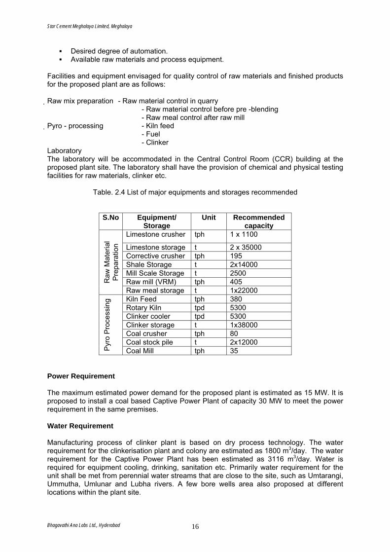
Table. 2.4 List of major equipments and storages recommended
S.No Equipment/
Storage Unit Recommended
capacity Limestone crusher tph 1 x 1100
Limestone storage t 2 x 35000 Corrective crusher tph 195 Shale Storage t 2x14000 Mill Scale Storage t 2500 Raw mill (VRM) tph 405 R
aw M
ater
ial
Pre
para
tion
Raw meal storage t 1x22000 Kiln Feed tph 380 Rotary Kiln tpd 5300 Clinker cooler tpd 5300 Clinker storage t 1x38000 Coal crusher tph 80 Coal stock pile t 2x12000
Pyr
o P
roce
ssin
g
Coal Mill tph 35 Power Requirement The maximum estimated power demand for the proposed plant is estimated as 15 MW. It is proposed to install a coal based Captive Power Plant of capacity 30 MW to meet the power requirement in the same premises. Water Requirement Manufacturing process of clinker plant is based on dry process technology. The water requirement for the clinkerisation plant and colony are estimated as 1800 m3/day. The water requirement for the Captive Power Plant has been estimated as 3116 m3/day. Water is required for equipment cooling, drinking, sanitation etc. Primarily water requirement for the unit shall be met from perennial water streams that are close to the site, such as Umtarangi, Ummutha, Umlunar and Lubha rivers. A few bore wells area also proposed at different locations within the plant site.
Bhagavathi Ana Labs Ltd., Hyderabad 16
Star Cement Meghalaya Limited, Meghalaya
Utilities Water supply The water requirement for the plant and colony are estimated as 1800 m3/day. The water requirement for the Captive Power Plant has been estimated as 3116 m3/day. Water is required for equipment cooling, drinking, sanitation, horticulture, etc. Normally, the water requirements shall be met from perennial water streams that are close to the site, such as Umtargnai, Ummutha, Umlunar and Lubha rivers. A few bore wells area also proposed at different locations within the plant site. A suitably designed water treatment and chlorination plant shall be installed. Water shall be stored in a underground tank for plant and overhead (OH) tank for drinking purpose. For plant equipment, water shall be recirculated after cooling to avoid any wastage and only losses shall be made up from fresh water. Compressed air supply Centralized compressor and blower room have been envisaged for the sake of overall economy, effectiveness and ease of operation and maintenance. The compressed air is required mainly for dust collection equipment and operation of pneumatic valves. Blowers will be used for aeration of silos. One no. centralized compressor rooms are proposed for the proposed plant. Blowers may be suitably accommodated under buildings/ silos near points of utility. Central Control Room (CCR) A CCR building is envisaged to be constructed at the plant site. Operation of the raw mill, coal mill, pyro processing section and cement mill will be carried out from this control room. Pollution control equipment The installation of the following pollution control equipment are proposed:
Bag house for raw mill and PH fan exit gases Cooler ESP for cooler vent gases Coal mill bag filter Cement mill bag filter Bag filters for dedusting of storages and auxiliaries in different departments
Pollution monitoring equipment
On line Gas analyser for O2, CO emission at Kiln inlet, PC outlet and PH outlet On line dust monitor at kiln stack, clinker cooler stack. Off line dust emission monitoring kit
2.4 Detailed Process & Technology Description-Power Plant It is proposed to set up the captive power plant of 30 MW capacity. Fuel proposed for the CPP is Meghalaya coal and Bamboo. Hence, a conventional Rankine steam cycle plant has been considered for 30 MW CPP. 2.4.1 Fuel Sources and Specification The fuel envisaged for the boiler is Meghalaya coal and lops & Tops of Bamboo. Fuels Coal and Bamboo chips are available in the adjoining regions of the study area. The raw material is procured from the local market nearby in the state.
Bhagavathi Ana Labs Ltd., Hyderabad 17
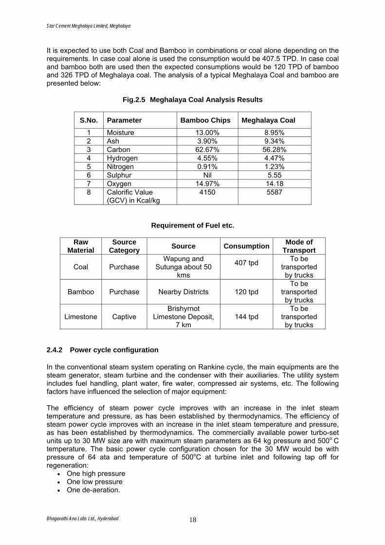
Star Cement Meghalaya Limited, Meghalaya
It is expected to use both Coal and Bamboo in combinations or coal alone depending on the requirements. In case coal alone is used the consumption would be 407.5 TPD. In case coal and bamboo both are used then the expected consumptions would be 120 TPD of bamboo and 326 TPD of Meghalaya coal. The analysis of a typical Meghalaya Coal and bamboo are presented below:
Fig.2.5 Meghalaya Coal Analysis Results
S.No. Parameter Bamboo Chips Meghalaya Coal
1 Moisture 13.00% 8.95% 2 Ash 3.90% 9.34% 3 Carbon 62.67% 56.28% 4 Hydrogen 4.55% 4.47% 5 Nitrogen 0.91% 1.23% 6 Sulphur Nil 5.55 7 Oxygen 14.97% 14.18 8 Calorific Value
(GCV) in Kcal/kg 4150 5587
Requirement of Fuel etc.
Raw Material
Source Category Source Consumption Mode of
Transport
Coal Purchase Wapung and
Sutunga about 50 kms
407 tpd
To be transported by trucks
Bamboo Purchase Nearby Districts 120 tpd To be
transported by trucks
Limestone Captive Brishyrnot
Limestone Deposit, 7 km
144 tpd To be
transported by trucks
2.4.2 Power cycle configuration In the conventional steam system operating on Rankine cycle, the main equipments are the steam generator, steam turbine and the condenser with their auxiliaries. The utility system includes fuel handling, plant water, fire water, compressed air systems, etc. The following factors have influenced the selection of major equipment: The efficiency of steam power cycle improves with an increase in the inlet steam temperature and pressure, as has been established by thermodynamics. The efficiency of steam power cycle improves with an increase in the inlet steam temperature and pressure, as has been established by thermodynamics. The commercially available power turbo-set units up to 30 MW size are with maximum steam parameters as 64 kg pressure and 500o C temperature. The basic power cycle configuration chosen for the 30 MW would be with pressure of 64 ata and temperature of 500oC at turbine inlet and following tap off for regeneration:
• One high pressure • One low pressure • One de-aeration.
Bhagavathi Ana Labs Ltd., Hyderabad 18
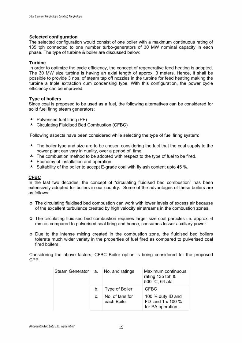
Star Cement Meghalaya Limited, Meghalaya
Selected configuration The selected configuration would consist of one boiler with a maximum continuous rating of 135 tph connected to one number turbo-generators of 30 MW nominal capacity in each phase. The type of turbine & boiler are discussed below: Turbine In order to optimize the cycle efficiency, the concept of regenerative feed heating is adopted. The 30 MW size turbine is having an axial length of approx. 3 meters. Hence, it shall be possible to provide 3 nos. of steam tap off nozzles in the turbine for feed heating making the turbine a triple extraction cum condensing type. With this configuration, the power cycle efficiency can be improved. Type of boilers Since coal is proposed to be used as a fuel, the following alternatives can be considered for solid fuel firing steam generators:
Pulverised fuel firing (PF) Circulating Fluidised Bed Combustion (CFBC)
Following aspects have been considered while selecting the type of fuel firing system:
The boiler type and size are to be chosen considering the fact that the coal supply to the power plant can vary in quality, over a period of time.
The combustion method to be adopted with respect to the type of fuel to be fired. Economy of installation and operation. Suitability of the boiler to accept E-grade coal with fly ash content upto 45 %.
CFBC In the last two decades, the concept of “circulating fluidised bed combustion” has been extensively adopted for boilers in our country. Some of the advantages of these boilers are as follows:
The circulating fluidised bed combustion can work with lower levels of excess air because of the excellent turbulence created by high velocity air streams in the combustion zones.
The circulating fluidised bed combustion requires larger size coal particles i.e. approx. 6 mm as compared to pulverised coal firing and hence, consumes lesser auxiliary power.
Due to the intense mixing created in the combustion zone, the fluidised bed boilers tolerate much wider variety in the properties of fuel fired as compared to pulverised coal fired boilers.
Considering the above factors, CFBC Boiler option is being considered for the proposed CPP.
Steam Generator a. No. and ratings Maximum continuous rating 135 tph & 500 oC, 64 ata.
b. Type of Boiler CFBC c. No. of fans for
each Boiler 100 % duty ID and FD and 1 x 100 % for PA operation .
Bhagavathi Ana Labs Ltd., Hyderabad 19
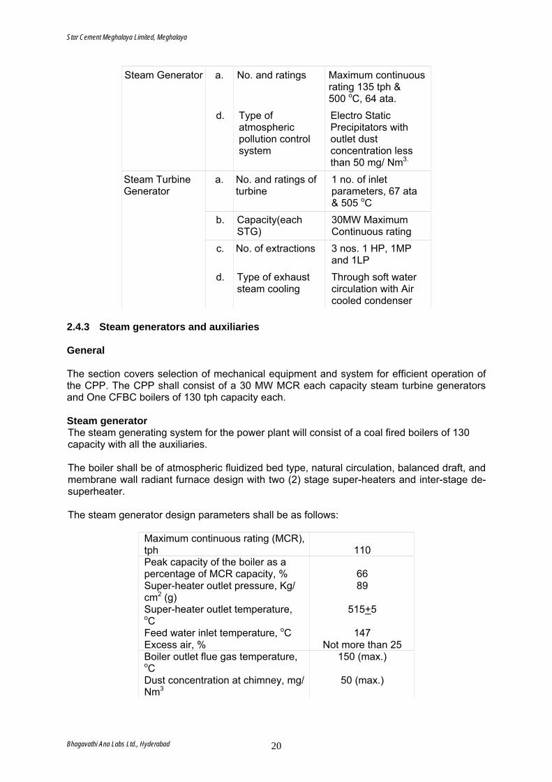
Star Cement Meghalaya Limited, Meghalaya
Steam Generator a. No. and ratings Maximum continuous rating 135 tph & 500 oC, 64 ata.
d. Type of atmospheric pollution control system
Electro Static Precipitators with outlet dust concentration less than 50 mg/ Nm3.
Steam Turbine Generator
a. No. and ratings of turbine
1 no. of inlet parameters, 67 ata & 505 oC
b. Capacity(each STG)
30MW Maximum Continuous rating
c. No. of extractions 3 nos. 1 HP, 1MP and 1LP
d. Type of exhaust steam cooling
Through soft water circulation with Air cooled condenser
2.4.3 Steam generators and auxiliaries General The section covers selection of mechanical equipment and system for efficient operation of the CPP. The CPP shall consist of a 30 MW MCR each capacity steam turbine generators and One CFBC boilers of 130 tph capacity each. Steam generator The steam generating system for the power plant will consist of a coal fired boilers of 130 capacity with all the auxiliaries. The boiler shall be of atmospheric fluidized bed type, natural circulation, balanced draft, and membrane wall radiant furnace design with two (2) stage super-heaters and inter-stage de-superheater. The steam generator design parameters shall be as follows:
Maximum continuous rating (MCR), tph 110 Peak capacity of the boiler as a percentage of MCR capacity, % 66 Super-heater outlet pressure, Kg/ cm2 (g)
89
Super-heater outlet temperature, oC
515+5
Feed water inlet temperature, oC 147 Excess air, % Not more than 25 Boiler outlet flue gas temperature, oC
150 (max.)
Dust concentration at chimney, mg/ Nm3
50 (max.)
Bhagavathi Ana Labs Ltd., Hyderabad 20
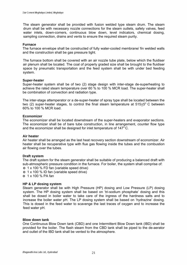
Star Cement Meghalaya Limited, Meghalaya
The steam generator shall be provided with fusion welded type steam drum. The steam drum shall be with necessary nozzle connections for the steam outlets, safety valves, feed water inlets, down-comers, continuous blow down, level indicators, chemical dosing, sampling connection, drains and vents to ensure the required steam purity. Furnace The furnace envelope shall be constructed of fully water-cooled membrane/ fin welded walls and the construction shall be gas pressure tight. The furnace bottom shall be covered with an air nozzle tube plate, below which the fluidiser air plenum shall be located. The coal of properly graded size shall be brought to the fluidiser space by pneumatic transportation and the feed system shall be with under bed feeding system. Super-heater Super-heater system shall be of two (2) stage design with inter-stage de-superheating to achieve the rated steam temperature over 60 % to 100 % MCR load. The super-heater shall be combination of convection and radiation type. The inter-stage attemperator or a de-super-heater of spray type shall be located between the two (2) super-heater stages, to control the final steam temperature at 515+5o C between 60% to 100 % MCR load. Economizer The economizer shall be located downstream of the super-heaters and evaporator sections. The economizer shall be of bare tube construction, in line arrangement, counter flow type and the economizer shall be designed for inlet temperature of 147o C. Air heater Air heater shall be arranged as the last heat recovery section downstream of economizer. Air heater shall be recuperative type with flue gas flowing inside the tubes and the combustion air flowing over the tubes. Draft system The draft system for the steam generator shall be suitable of producing a balanced draft with sub-atmospheric pressure condition in the furnace. For boiler, the system shall comprise of:
1 x 100 % FD fan (variable speed drive) 1 x 100 % ID fan (variable speed drive) 1 x 100 % PA fan
HP & LP dosing system Steam generator shall be with High Pressure (HP) dosing and Low Pressure (LP) dosing system. The HP dosing system shall be based on ‘tri-sodium phosphate’ dosing and this shall be dosed in boiler water to take care of the ingress of the hardness salts and to increase the boiler water pH. The LP dosing system shall be based on ‘hydrazine’ dosing. This is dosed in the feed water to scavenge the last traces of oxygen and to increase the feed water pH. Blow down tank One Continuous Blow Down tank (CBD) and one Intermittent Blow Down tank (IBD) shall be provided for the boiler. The flash steam from the CBD tank shall be piped to the de-aerator and outlet of the IBD tank shall be vented to the atmosphere.
Bhagavathi Ana Labs Ltd., Hyderabad 21
Star Cement Meghalaya Limited, Meghalaya
De-aerator One De-aerator of de-aerating capacity equal to twenty percent (20 %) higher than the gross MCR steam generation capacity of boiler with a de-aerated water storage tank of minimum 20 minutes operation will be provided. Boiler feed water pump Two working and one standby boiler feed water pumps have been envisaged for complete power plant. Steam turbine and auxiliaries Steam turbine This project envisages 30 MW triple extraction-cum-condensing turbo-generators, one for each phase.
The turbine shall be designed for the operation with the inlet steam parameters at 67 ata and 505o C and shall be with automatic controlled extraction steam.
Turbines will have air cooled Condenser and exhaust pressure shall be around 0.17 Kg/ cm2.
The turbines shall be horizontal, single cylinder, triple extraction-cum-condensing type. All casings and stator blade carriers shall be horizontally split.
The controlled extraction steam from the turbine shall be delivered to the heaters/ de-aerators in saturated condition.
A de-superheater to bring the steam temperature from the extraction steam temperature down to the required level is envisaged.
Lubrication system A pressure lubrication and control oil system shall be provided for the turbo-generator unit to supply oil at the required pressure to the steam turbine, gearbox, generator and governing system. The lubrication oil system shall supply oil to the turbine generator under all the load conditions, including the turning gear operation. The oil system with each Turbine shall be following:
One hundred percent (100 %) capacity centrifugal/ gear type, main oil pump. One (1) no. of one hundred percent (100 %) capacity auxiliary oil pump of centrifugal
type, arranged to cut in automatically if the oil pressure falls to a preset value. This pump shall also meet the requirements during the start up and shut down.
One (1) no., centrifugal type, DC emergency oil pump to provide adequate lubrication in the event of a failure of the main driven pump. This pump also shall cut in automatically at a preset value of the oil pressure.
Emergency gravity lube oil system comprising of overhead tank with SS lining and complete interconnecting SS oil piping.
Two nos. 100 % capacity (one working and one standby) water-cooled air coolers. Two 100 % duty oil filters
Turbine governer The turbine governing system shall be electro-hydraulic type, designed for high accuracy, speed and sensitivity of response. The governor shall ensure controlled acceleration of the turbo generator and shall prevent over-speed without tripping the unit under any operating condition or in the even maximum load rejection. The governor shall be configurable in the field. The governing system shall have the following important functions:
Speed control Over speed control Load control Steam pressure control
Bhagavathi Ana Labs Ltd., Hyderabad 22
Star Cement Meghalaya Limited, Meghalaya
The governing system shall be digital governor with all parameter control from plant distributed control system (DCS) system. Air cooled condenser The waste heat produced in the thermal process of the plant has to be transferred to the atmosphere by using adequate cooling system. Environmental concern and climatic conditions are the main factors in the selection of the most suitable power station process. Due easy availability of water, Turbine Condenser will be Air-cooled Surface condenser type. Exhaust pressure shall be around 0.17 Kg/ cm2. Turbine control The turbine control shall be through the centrally located PC based PLC system. The control system shall provide redundancy for key functions by use of separate sensors and monitors. The control system shall include all the standard control monitoring and alarming. In addition to centralized monitoring, some of the essential parameters mounted in local shall be:
Inlet steam pressure temperature and flow Uncontrolled extraction steam pressure and temperature Exhaust steam pressure, temperature and flow Lube oil header pressure Control oil header pressure Steam turbine/ generator speed indicator Steam turbine/ generator stop push button Turbine back propose control Emergency shutdown push button
Coal crushing & storage in bunker For boiler application, the coal has to be reduced to average 6 mm size which necessitates crushing of the coal. The vibrating screen shall be provided before crusher to screen out coal size below 6 mm and coarse particle shall be fed to the impact crusher. The output shall be fed to the vibrating screen. The oversize particle above 6mm shall be re-circulated. The screened material shall be conveyed to the coal bunker near the boiler. 2.4.4 Utilities and service Compressed air system Compressed air is required for meeting the needs of various mechanical equipment and for instruments. A centralized compressor is envisaged to be installed for this economizing the overall cost. The compressors shall be fitted with all auxiliaries like receivers, dryers, moisture and oil separators and also necessary control panels. The compressor dew point shall be restricted to -30oC. Outlet from service air compressor shall be routed to various areas like steam generator, TG Hall extension, coal handling, etc. In addition to this, a separate compressor for cleaning and other miscellaneous purposes shall be provided. HP & LP piping The piping for the CPP has been divided as follows:
Power cycle piping Low pressure utility piping Cooling water piping
Bhagavathi Ana Labs Ltd., Hyderabad 23

Star Cement Meghalaya Limited, Meghalaya
Fire water piping Compressed air piping
Power cycle piping The power cycle piping of each unit shall consist of mainly the following:
Main stream piping from generator to turbine inlet Interconnection between main steam piping and auxiliary steam header through a
Pressure Reducing and Desuperheating Station (PRDS) Boiler feed water pump suction piping Boiler feed water suction piping and common feed water header Boiler feed water pump recirculation piping Condensate extraction pump discharge piping Condensate extraction pump suction piping Heat exchanger piping Boiler blow down piping
Low pressure utility piping
Raw water Reverse Osmosis (RO) Plant water
Cooling water piping
Heat Exchanger for main plant area Heat Exchanger for compressed air system
Fire fight piping
For fire Hydrants Compressed air piping
Instrument air Service air
Fire protection piping Fire protection in the proposed power plant is envisaged for the following purposes:
Early Detection Alarm Suppression of Fire
The entire fire protection shall be designed to meet above requirement effectively and quickly as per the guidelines set out by the Tariff Advisory Committee. For detection of fire, necessary smoke and heat detectors and manual call buttons with centralized zonal control room have been envisaged. Suitable alarm system shall also be provided along with detection system. Fire protection system shall consist of:
Fire Hydrants Portable Fire Extinguishers Heat sensing cable for cable trays Spray system for power transfer & lube oil system
The hydrant system shall consist of one electric driven water pump and one diesel engine driven standby pump along with necessary length of hose to be laid around vulnerable points. Various water pumping points shall be provided along the length of hose as per requirement.
Bhagavathi Ana Labs Ltd., Hyderabad 24
Star Cement Meghalaya Limited, Meghalaya
Portable fire extinguishers shall consist of a combination of different type of extinguishers like foam type, CO2 type, etc. Air conditioning Air conditioning has been considered for the following:
Control room Group level controller and Electronic panel room UPS panel room SWAS room
Based on estimated heat load, the capacity of air-conditioning unit works out to:
15 TR for controller and electronic panel room 20 TR for Control room 50 TR for UPS room and SWAS room
Based on the heat load, operational ease, flexibility and reliability of the system, the air cooled package type is being considered. Ventilation The ventilation system for turbine building is provided to evacuate the heat liberated from the operating equipment and to prevent ingress of atmospheric dust. For effective draft, induced draft ventilation system shall be provided for turbine building by installing sufficient roof exhausters. All the air entering the turbine building shall rise through various floor grills/ gratings and the hot air shall finally be exhausted through roof exhausters. For switchgear/ MCC room, the clean air is required for protection of the equipment. Air filters are used in supply air and dampers are provided to maintain positive pressure of 3-4 mmWG inside the room. In order to have controlled atmosphere, the ventilation system shall consist of:
Air intake louvers Viscous and fine filters Evaporative cooler Centrifugal blower
2.4.5 Instrumentation and Control System General This section covers the design philosophy to be adopted for Instrumentation and Control (I&C) system for the proposed CPP and Power Evacuation system. Design philosophy and system configuration Station shall be provided with PLC based comprehensive integrated Instrumentation and Control system to operate, control and monitor Steam Generator and auxiliaries, steam turbine generator and auxiliaries, power evacuation and the plant common auxiliary system with a distributed structure. This has the following advantages: • Increased reliability • Better availability • Higher system security • Increased flexibility • Modularity and expandability • Higher maintainability • Drift free control • Lower power consumption
Bhagavathi Ana Labs Ltd., Hyderabad 25
Star Cement Meghalaya Limited, Meghalaya
• Improved man-machine communication with colour graphic VDU based control stations
The PLC system will have complete control capabilities that include closed loop control,
The PLC system will include following main sub-systems operating in a totally integrated
The plant supervisory system shall perform control of process parameters like flow,
The plant shall be divided into three sub-sections as given below:
& Utilities
operation, interlocking, plant shut-down, PI/ PID control and
fety and Burner management related digital inputs/ outputs shall be monitored
ce sub-system shall have an engineering console primarily for tuning,
lant s
entire CPP shall be effected from the Supervisory
icated such that
ed control system shall be controlling operations of:
, Ash handling & Plant water system)
nalytical instruments
lytical Instruments would be provided for continuous monitoring of
• Faster response time
open loop control, computation and interfacing for data acquisition, graphic displays, logging, annunciation, data storage and retrieval. •
fashion for the total plant operation.
temperature, pressure, level, power, current, voltage and analytical. In addition, it shall also perform functions like performance calculations, utility displays, operator guidance message displays, logs, historical storage and retrieval etc.
Boiler Turbine Auxiliaries
Execution of sequenceplant start-up for the above sub-sections shall be achieved with respective group level PLCs. PLCs will be interfaced with Supervisory Processor located in the control room. The saand controlled. Engineer interfaconfiguring, programming and maintaining the system.
Redundant communication sub-system shall be considered for interconnecting all the PLCs & sub systems with plant supervisory control system.
upervisory system P The operation and control of the
Processors in the Central Control Room (CCR). For ease of operation and reliability, the operator interface with the plant shall be through a set of three operator stations and one engineering station, each completely independent of the other.
conditions, each operator station shall be dedUnder normal operating
the operator in-charge for a particular area of operation shall be able to carry out his activities independently. In case of failure of any one of the operator stations (hardware/ display), any one of the operating stations shall be assignable to monitor/ control the additional area of operation, without any disturbance to the plant operation. The system configuration shall be with universal data base.
The distribut• Boiler & auxiliaries • Turbine & auxiliaries• Utilities (Coal handling
AAdequate number of anademineralised water, condensate, feed water for plant operation & pollution control requirement. Local instruments
Bhagavathi Ana Labs Ltd., Hyderabad 26
Star Cement Meghalaya Limited, Meghalaya
Adequate number of local instruments would be provided to enable local operators to nitor equipment/ process operation.
All the thermocouples and RTDs shall be of duplex type.
C office suitable technical office & laboratory / QC office shall be constructed for the project
nd Security office suitable General stores, administrative, time & security office shall be constructed for the
small dispensary with first aid facilities will be provided in the plant premises.
ire detection and extinguishing system shall be provided in all buildings.
wo nos. electronic weighbridges are envisaged to take care of the incoming and outgoing . These may be located near the main entrance of the plant.
pace shall be provided in the packing plant department for the storage of bags at the ite.
he parking for trucks may be planned outside the main gate for the proposed plant.
residential colony to provide accommodation for key plant personnel is required at the plant sites. Initially, senior management and essential services related personnel
.5 Infrastructure
utilities and other infrastructural facilities in the cement plant and ower plant. Adequate storage facility for limestone in open stack yard and clinker and coal
.6 Manpower he total manpower requirement of the plant will be 475, out of which 196 persons of
rsons in various shifts have been envisaged on contract.
supervise and mo All transmitters for measurement and control will be electronic type of two-wire system
with galvanically isolated 4-20 mA DC output.
Miscellaneous services Technical & Laboratory/QAactivities and operation phase at the site. General Stores, Administrative & Time aAproject activities and operation phase at the site. Dispensary A Fire fighting system F Weighbridge Tmaterials at site Bags Godown Sproposed plant s Parking T Colony Aproposedwould be accommodated in the colony. Later, the number of houses in the colony can be increased, if required. The colony shall have other facilities like dispensary, shopping complex, guesthouse, etc 2 SCML will install complete punder closed sheds will be provided to meet the requirements of the plant. Workshop facility both for mechanical and electrical equipment repairs and maintenance is also proposed. 2Tgeneral shift and 279 pe
Bhagavathi Ana Labs Ltd., Hyderabad 27
Star Cement Meghalaya Limited, Meghalaya
2.7 Township CML. will provide a common full-fledged township comprising of housing facilities for plant,
onnel and supporting staff along with other amenities such as School,
.8 Land Break Up near Lumshnong for its proposed Cement Plant,
township. Of which 28 ha will be allotted for the greenbelt.
Smine and security persGuest House, Dispensary, and Shopping Complex etc. 2SCML proposed to acquire 75 ha of landCaptive Power Plant and
Bhagavathi Ana Labs Ltd., Hyderabad 28

REIA & EMP
Star Cement Meghalaya Limited, Meghalaya
Bhagavathi Ana Labs Ltd., Hyderabad 31
3.0 PRESENT ENVIRONMENTAL SCENARIO
Any developmental activity may cause some environmental impacts on the surrounding
environment. In order to know the cumulative impacts due to the proposed plant on the
surrounding environment, it is very important to know the baseline environmental status in
the study area. This section provides the background information about the study area with
an overall description of environmental baseline of the area where the proposed plant would
take place. Various baseline environmental parameters, with each respective inference, as
per the table below were monitored as primary data and the secondary data was collected
for the analysis.
3.0.1 Study Area The proposed project is set up near Lumshnong, P.O. Khliehriat, Jaintia Hills District,
Meghalaya. The study area is 10 km radial distance surrounding the project site.
Table-3.1 Baseline Environmental Parameters
Parameter Inference
Micro-meteorological studies
To assess the air pollution impacts on the neighbouring environment.
Air quality data
To assess the baseline air quality status prior to the commencement of the project. Predicted concentrations will be superimposed on the baseline values to know the overall baseline scenario during the operational phase.
Water quality and soil quality in the study area
Even though the proposed plant does not generate any wastewater from the process, it is proposed to identify the baseline water quality for future reference.
Ecological environment
Baseline ecological data was collected to identify any presence of endangered species and the impact due to proposed plant.
Land use and land cover data
To identify land cover and land use pattern in the study area. This forms the actual baseline data in the study area. The same was compared with Survey of India Toposheet 83C/8.
Socio economic and demographic data
Relevant secondary data has been collected from various sources to know the baseline socioeconomic status in the study area.
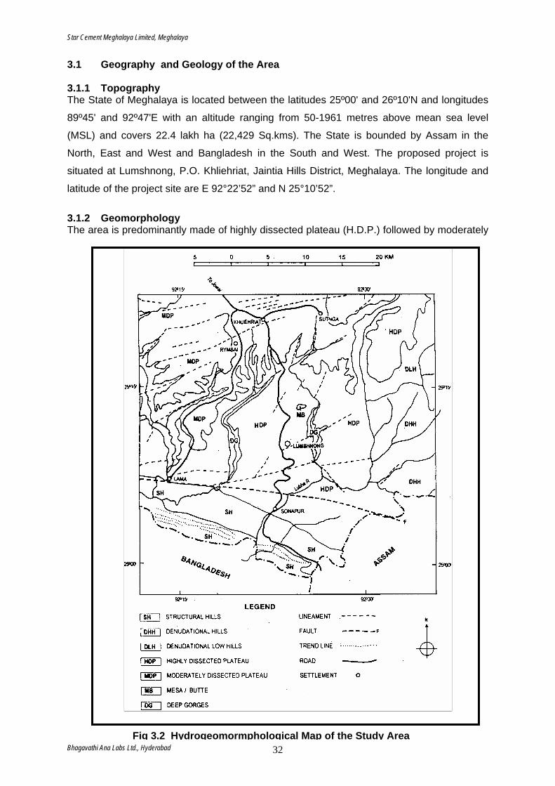
Star Cement Meghalaya Limited, Meghalaya
3.1 Geography and Geology of the Area 3.1.1 Topography The State of Meghalaya is located between the latitudes 25º00' and 26º10'N and longitudes
89º45' and 92º47'E with an altitude ranging from 50-1961 metres above mean sea level
(MSL) and covers 22.4 lakh ha (22,429 Sq.kms). The State is bounded by Assam in the
North, East and West and Bangladesh in the South and West. The proposed project is
situated at Lumshnong, P.O. Khliehriat, Jaintia Hills District, Meghalaya. The longitude and
latitude of the project site are E 92°22’52” and N 25°10’52”.
3.1.2 Geomorphology The area is predominantly made of highly dissected plateau (H.D.P.) followed by moderately
Bhagavat 32Fig 3.2 Hydrogeomormphological Map of the Study Area
hi Ana Labs Ltd., Hyderabad
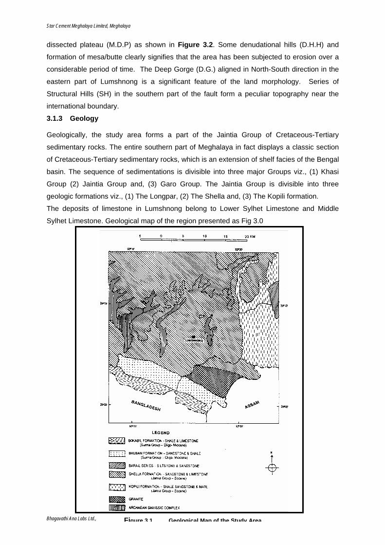
Star Cement Meghalaya Limited, Meghalaya
dissected plateau (M.D.P) as shown in Figure 3.2. Some denudational hills (D.H.H) and
formation of mesa/butte clearly signifies that the area has been subjected to erosion over a
considerable period of time. The Deep Gorge (D.G.) aligned in North-South direction in the
eastern part of Lumshnong is a significant feature of the land morphology. Series of
Structural Hills (SH) in the southern part of the fault form a peculiar topography near the
international boundary.
3.1.3 Geology Geologically, the study area forms a part of the Jaintia Group of Cretaceous-Tertiary
sedimentary rocks. The entire southern part of Meghalaya in fact displays a classic section
of Cretaceous-Tertiary sedimentary rocks, which is an extension of shelf facies of the Bengal
basin. The sequence of sedimentations is divisible into three major Groups viz., (1) Khasi
Group (2) Jaintia Group and, (3) Garo Group. The Jaintia Group is divisible into three
geologic formations viz., (1) The Longpar, (2) The Shella and, (3) The Kopili formation.
The deposits of limestone in Lumshnong belong to Lower Sylhet Limestone and Middle
Sylhet Limestone. Geological map of the region presented as Fig 3.0
Bhagavathi Ana Labs Ltd., Hyderabad 33Figure 3.1 Geological Map of the Study Area

Star Cement Meghalaya Limited, Meghalaya
The regional stratigraphic sequence of the area is a follows:
Age Group/Series Stage Beds
Oligocene Barail Series - Sandstone & Shale Upper Eocene
Garo Group Kopili Formation Grey shale with alternate layers of Sandstone & Siltstone
Lower to Middle Eocene
Jaintia Group Sylhet Limestone Prang Limestone Narpuh Sandstone Umlatdoh Limestone Lakadong Sandstone Lakadong Limestone
Palaeocene ----- Therria Sandstone
Sandstone
3.1.4 Hydrogeology Lumshnong is located at Highly Dissected Plateau (HDP). The area is composed of
sedimentary rocks of Cretaceous-Tertiary origin. Some fractures are also present in the
region. The area is characterized mainly by Karst topography (Limestone) followed by
sandstone, granite, and gneisses resulting in undulating uplands with gullies. The area
possesses semi-confined to confined aquifers with moderate permeability suitable for bore
wells and even deep bore wells along fracture zone. Presence of some cavernous limestone
areas indicates the underground water availability in this region. The area is marked with
springs and seepages. Therefore, the area is suitable for dug wells and shallow tube wells etc.
Many perennial streams are available in the area, which often make principal source of water
for human use.
Parallel deep gorges aligned in North-South direction in the eastern and western part of
Lumshnong are also present in the region. These areas are the formations of Archean
Gneissic Complex. There are highly deformed massive rocks with fractures. The gorges are
often very steep and interspersed with sharp crested hills. As a result, parallel deep valleys
are noticed in the east and west part of Lumshnong.
Hydrgeologically, the Jaintia district can be divided into three units namely- consolidated,
semi-consolidated and unconsolidated formations. Consolidated formations comprise of the
oldest rock formation namely the peneplained genesis complex and quartzite. Groundwater
occurs under both water table and semi-confined condition in these consolidated formations.
Unconsolidated formations mainly are represented by recent alluvium formation occurring near
the southern fringe of the district adjacent to Bangladesh.
Bhagavathi Ana Labs Ltd., Hyderabad 34
Star Cement Meghalaya Limited, Meghalaya
The major part of the district is covered by semi-consolidated formation covering Amlarem and
Khliehriat blocks constituting the Shella formation and study area is also part of the same. This
type of formation has:
• fairly thick and discontinuous aquifer down to 250m. Groundwater occurs under semi-
confined to confined conditions. Water level rests at 4-9m below ground level and yield
ranges from 25–150 m³/hr; and
• Groundwater occurs under unconfined to semi-confined conditions in cavernous
limestone & sandstone and yield ranges from 25–150 m³/hr.
3.1.5 Drainage pattern The geological formations, its resultant topography and tendency of headward erosion by
rainwater have led to the creation of drainage network in the area. The prevailing weather and
climate in the study area is characterized by heavy rainfall, which favours the action of
streams to a considerable extent.
Predominantly two different kinds of drainage patterns can be seen in the study area. They
are mainly dendretic and trellis pattern. The Lubha and Shesyampa are the main rivers in
study area showing common dendretic patterns. In a massively dissected region of horizontal
strata, the smaller streams show no predominant directional orientation or control. Lubha river
and its tributaries Um Lunar, Um Saugat and Dongtangle depict clear picture of dendretic or
tree like drainage pattern in the study area. This kind of drainage pattern has generally
developed in the most dissected parts of the plateau. In this case the consequent river
receives number of tributaries, which are fed by innumerable smaller streams. The
Seshympa, the main river controlling the drainage pattern west of NH-44, with the streams of
Wah Lariang, Umbadoh and Um Utha also shows similar dendretic pattern of drainage
system. The upper most part of Seshympa river from where it is originated shows trellis
pattern of drainage. In this case, the consequent stream cuts across the crest and
subsequent streams follow the strike valleys. Innumerable first order and second order
streams signify the high density of drainage system of the project area. Drainage pattern of
the area presented in Figure 3.1
Bhagavathi Ana Labs Ltd., Hyderabad 35
Star Cement Meghalaya Limited, Meghalaya
3.1.6 Water Balance of study area The area receives heavy rainfall and rainy season extends from April to October. The annual
rainfall recorded during the last one year at site is 4587mm. Major part of rainfall (about 80%)
is drained as surface runoff. The balance is charged into ground water through soil capping,
weathered sand stone, bedding planes, joints, fractures, solution cavities in the limestone and
the dolomite formations occurring in the study area.
The data on water balance of the area is not available from secondary sources. At present the
Groundwater resource estimation is going on for the entire state of Meghalaya based on the
latest Groundwater Estimation Committee (GEC 1997) norms. However, Groundwater
Resource Potential of Jaintia Hills District was calculated to be 120.36 million cubic meter
(MCM) based on GEC of 1984 norm. Out of the total resource, the utilizable resources were
estimated to be 102.31 MCM, which is 85% of the Gross recharge. As per norm, 15% of the
gross recharge has to be kept for drinking and allied purpose.
It is proposed to meet the water requirement for ongoing project from Umtyrngai nallahs from
April to October which is 200 m from project site and during the lean season i.e. from
November to March, part of water requirements shall have to drawn from a point 500 m further
east after the confluence of Umutha nallahs. Out of the buffer zone area of 314sq.km, an area
of about 40 sq. km forms the catchments area for sustaining surface and subsurface water
flow in Umtyrngai and Umutha nallahs.
The proposed water withdrawal locations at Umtyrngai and Umutha nallahs proposed to
sustain the water requirement of the plant are located on the downstream side of the villages
Lumshnong and Wahizar which depend upon for their water requirements from the upstream
side of the respective nallahs. No irrigation facilities are available in the area for cultivation
mainly due to rugged and rock terrain and absence of level and plain areas. The seasonal
agriculture and orchards in the area are sustained by monsoon rains. Further on the
downstream side there are no villages and commercial establishments and the nallahs join
Umlunar river further 2.0 km east which is a tributary of Lubha river.
3.1.7 Climate The climate in the study area is typically tropical. The region experiences tropical monsoonic
climate that varies from Western to Eastern part of the plateau. The lower elevated areas
experience fairly high temperature for most part of the year having a mean maximum of 23 to
Bhagavathi Ana Labs Ltd., Hyderabad 36
Star Cement Meghalaya Limited, Meghalaya
26° and a mean minimum of 12 to 17° C. The mean summer temperature is 26°C and the
mean winter temperature is 9° C. The mean annual rainfall varies from 2000-4000 mm with
most rainfall concentrated from May to September.
3.2 Baseline Environmental Results for the Study Period (Pre-monsoon ‘07) 3.2.1 Micro Meteorology A meteorological station was installed during the months from January, 2007 to March, 2007
to record various meteorological parameters on hourly basis to understand the Wind pattern,
Temperature variation, Relative humidity and Rainfall. On-site monitoring was undertaken for
recording of various meteorological variables, viz., wind speed, wind direction, relative
humidity and temperature in order to generate site-specific data. The data generated is
computed to obtain wind-roses of the area. The wind direction describes three quadrants of
24-hour time period. The wind roses plotted for the wind directions recorded during the study
period from January,2007 to March, 2007 is presented in this report.
Bhagavathi Ana Labs Ltd., Hyderabad 37
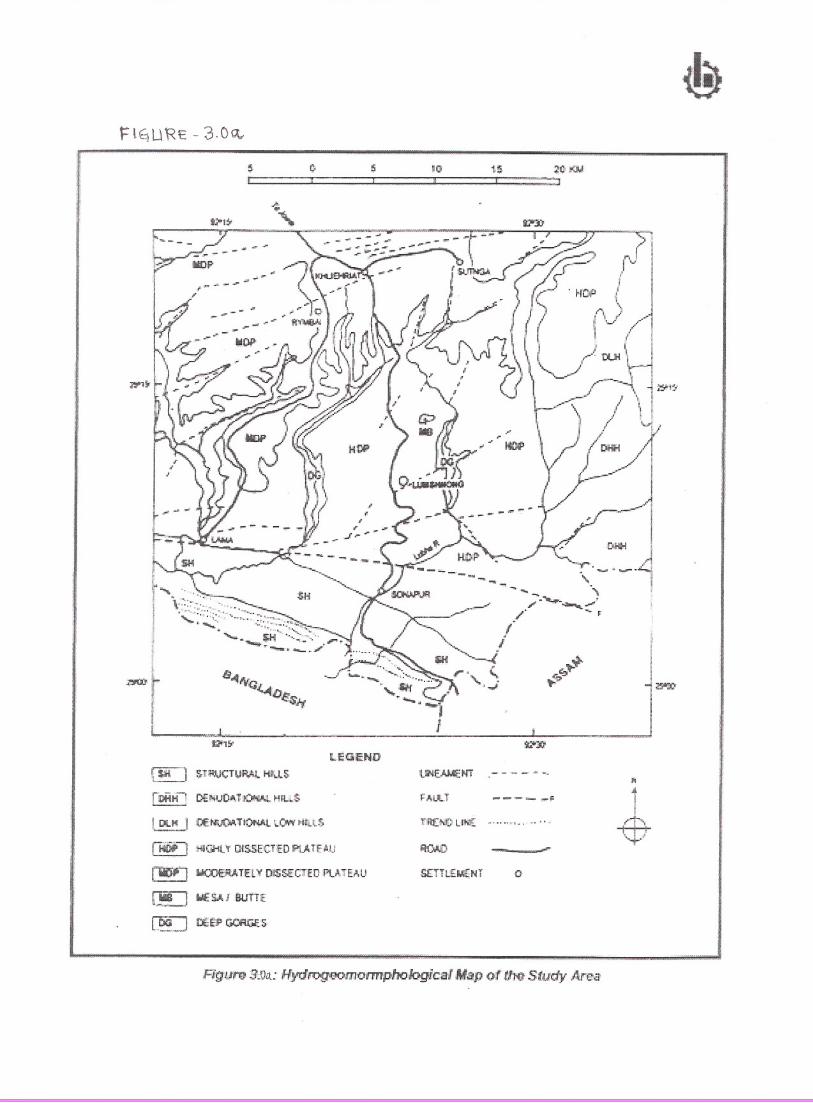
10:::::;;::::;:J
t !S :?I) :I{jJ.
, .. '..~ '-;J
c $;tl 1 501'~CT UP.1<t IitLl S
r~H' DE!,!IJCI"'b~ ~lfU:S
IDlJ-il I (:.€I'.llJQATH)f.;Al r...Clt'¥tltlf.S,
[Iijiioi :riJ("iHty Ol5SECTtD f'ij.TE'AJJ
~l WC~TEL'!!, DlS~-.EC1'E[!pt},TE},U
~ ~$.I. rBUiiE:
~-=:JtEsP C)ORG.I=.s
i-$
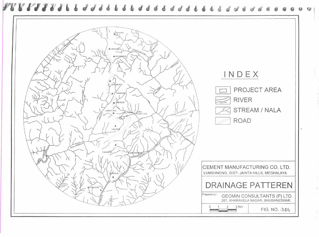
IN D EX
DRAINAGE PATTERENPrepared by- GEOMIN CONSULTANTS (P) LTD.
267, KHARAVElA NAGAR, BHUBANESWAR.
FIG. NO. -3.0b
[gJ PROJECT AREA
~ RIVER
~ STREAM / NALA
L ,:<:/"l ROAD
9 : ? ~ Km
CEMENT MANUFACTURING CO. LTD.lUMSHNONG, DIST- JAINTA HillS, MEGHALAYA
~J"JJJ&'d'~~~d4d~"'a4~~~~~~$O@~1
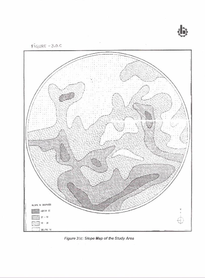
!
:I;1
Star Cement Meghalaya Limited, Meghalaya
3.2.1.1 Temperature The study period from January, 2007 to March, 2007 recorded minimum and maximum temperatures as 3.40 C and 35.10C respectively. 3.2.1.2 Relative humidity The region generally experiences tropical climatic condition throughout the year except
during winters. The lowest relative humidity recorded during the study period was 45% and
highest as 90%. Day times experience higher humidity levels as compared to nights.
3.2.1.3 Rainfall The study area experiences good rainfall. During study period total 203.5 mm rain fall was
recorded. It was observed that there was no rain fall during January, 2007 and rainy days
recorded were few during February & March, 2007.
3.2.1.4 Wind speed The average wind speed ranged from 0.6 m/s during the study period. The calm periods
were recorded as 46.62% of the total count of 22 08 hours during the study period.
3.2.1.5 Wind direction The pre-dominant wind direction in the study area is mostly South-west during the study
period.
Fig – 3.3 24 Hrs. Wind rose Diagram
Entire study period
Fig- 3.4 00-08 Hrs. Wind rose Diagram
Entire study period
Bhagavathi Ana Labs Ltd., Hyderabad 1
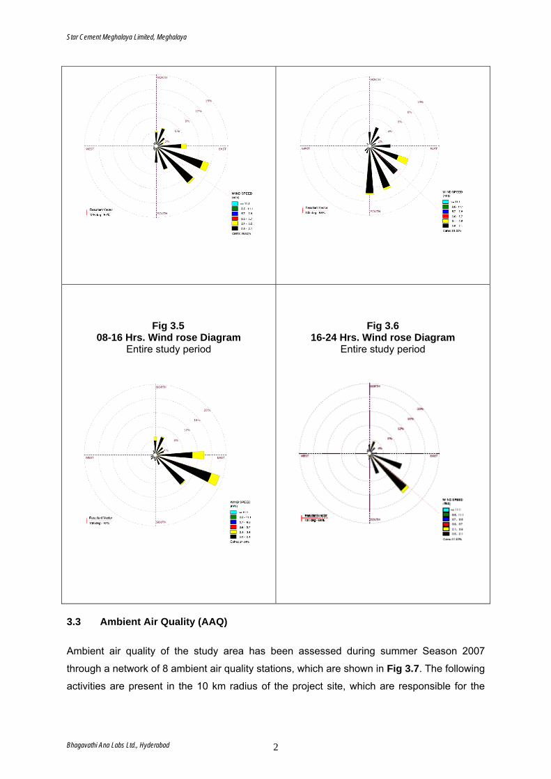
Star Cement Meghalaya Limited, Meghalaya
Fig 3.5 08-16 Hrs. Wind rose Diagram
Entire study period
Fig 3.6 16-24 Hrs. Wind rose Diagram
Entire study period
3.3 Ambient Air Quality (AAQ) Ambient air quality of the study area has been assessed during summer Season 2007
through a network of 8 ambient air quality stations, which are shown in Fig 3.7. The following
activities are present in the 10 km radius of the project site, which are responsible for the
Bhagavathi Ana Labs Ltd., Hyderabad 2
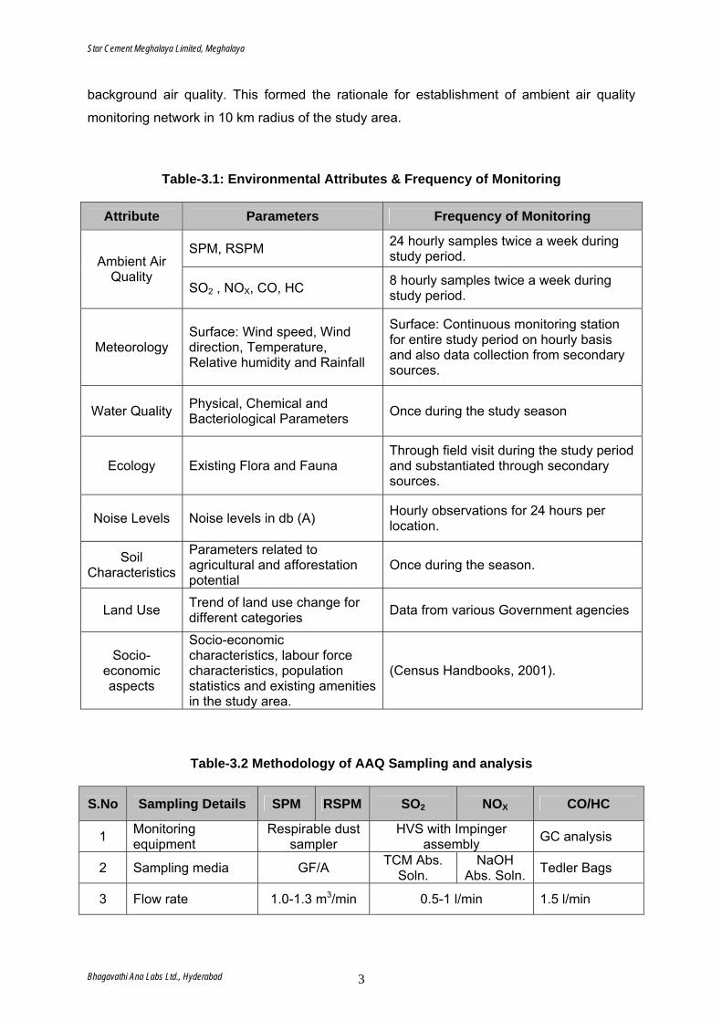
Star Cement Meghalaya Limited, Meghalaya
background air quality. This formed the rationale for establishment of ambient air quality
monitoring network in 10 km radius of the study area.
Table-3.1: Environmental Attributes & Frequency of Monitoring
Attribute Parameters Frequency of Monitoring
SPM, RSPM 24 hourly samples twice a week during study period. Ambient Air
Quality SO2 , NOX, CO, HC 8 hourly samples twice a week during
study period.
Meteorology Surface: Wind speed, Wind direction, Temperature, Relative humidity and Rainfall
Surface: Continuous monitoring station for entire study period on hourly basis and also data collection from secondary sources.
Water Quality Physical, Chemical and Bacteriological Parameters Once during the study season
Ecology Existing Flora and Fauna Through field visit during the study period and substantiated through secondary sources.
Noise Levels
Noise levels in db (A) Hourly observations for 24 hours per
location.
Soil Characteristics
Parameters related to agricultural and afforestation potential
Once during the season.
Land Use Trend of land use change for different categories Data from various Government agencies
Socio-economic aspects
Socio-economic characteristics, labour force characteristics, population statistics and existing amenities in the study area.
(Census Handbooks, 2001).
Table-3.2 Methodology of AAQ Sampling and analysis
S.No Sampling Details SPM RSPM SO2 NOX CO/HC
1 Monitoring equipment
Respirable dust sampler
HVS with Impinger assembly GC analysis
2 Sampling media GF/A TCM Abs. Soln.
NaOH Abs. Soln. Tedler Bags
3 Flow rate 1.0-1.3 m3/min 0.5-1 l/min 1.5 l/min
Bhagavathi Ana Labs Ltd., Hyderabad 3
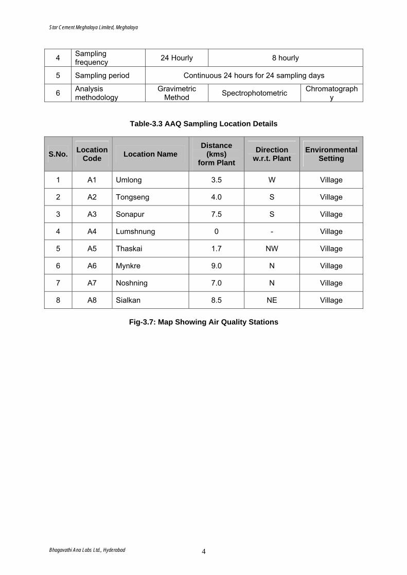
Star Cement Meghalaya Limited, Meghalaya
4 Sampling frequency 24 Hourly 8 hourly
5 Sampling period Continuous 24 hours for 24 sampling days
6 Analysis methodology
Gravimetric Method Spectrophotometric Chromatograph
y
Table-3.3 AAQ Sampling Location Details
S.No. Location Code Location Name
Distance (kms)
form Plant Direction
w.r.t. Plant Environmental
Setting
1 A1 Umlong 3.5 W Village
2 A2 Tongseng 4.0 S Village
3 A3 Sonapur 7.5 S Village
4 A4 Lumshnung 0 - Village
5 A5 Thaskai 1.7 NW Village
6 A6 Mynkre 9.0 N Village
7 A7 Noshning 7.0 N Village
8 A8 Sialkan 8.5 NE Village
Fig-3.7: Map Showing Air Quality Stations
Bhagavathi Ana Labs Ltd., Hyderabad 4
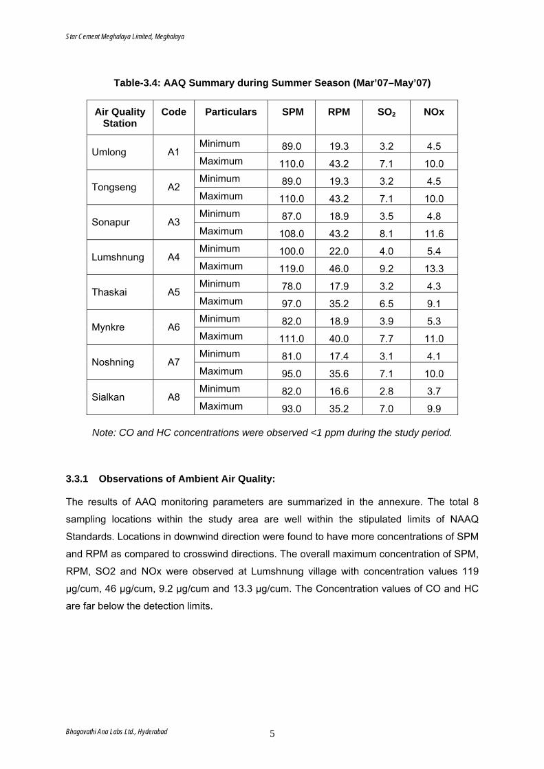
Star Cement Meghalaya Limited, Meghalaya
Table-3.4: AAQ Summary during Summer Season (Mar’07–May’07)
Air Quality Station
Code Particulars SPM RPM SO2 NOx
Minimum 89.0 19.3 3.2 4.5 Umlong A1 Maximum 110.0 43.2 7.1 10.0 Minimum 89.0 19.3 3.2 4.5 Tongseng A2 Maximum 110.0 43.2 7.1 10.0 Minimum 87.0 18.9 3.5 4.8 Sonapur A3 Maximum 108.0 43.2 8.1 11.6 Minimum 100.0 22.0 4.0 5.4 Lumshnung A4 Maximum 119.0 46.0 9.2 13.3 Minimum 78.0 17.9 3.2 4.3 Thaskai A5 Maximum 97.0 35.2 6.5 9.1 Minimum 82.0 18.9 3.9 5.3 Mynkre A6 Maximum 111.0 40.0 7.7 11.0 Minimum 81.0 17.4 3.1 4.1 Noshning A7 Maximum 95.0 35.6 7.1 10.0 Minimum 82.0 16.6 2.8 3.7 Sialkan A8 Maximum 93.0 35.2 7.0 9.9
Note: CO and HC concentrations were observed <1 ppm during the study period.
3.3.1 Observations of Ambient Air Quality: The results of AAQ monitoring parameters are summarized in the annexure. The total 8
sampling locations within the study area are well within the stipulated limits of NAAQ
Standards. Locations in downwind direction were found to have more concentrations of SPM
and RPM as compared to crosswind directions. The overall maximum concentration of SPM,
RPM, SO2 and NOx were observed at Lumshnung village with concentration values 119
µg/cum, 46 µg/cum, 9.2 µg/cum and 13.3 µg/cum. The Concentration values of CO and HC
are far below the detection limits.
Bhagavathi Ana Labs Ltd., Hyderabad 5
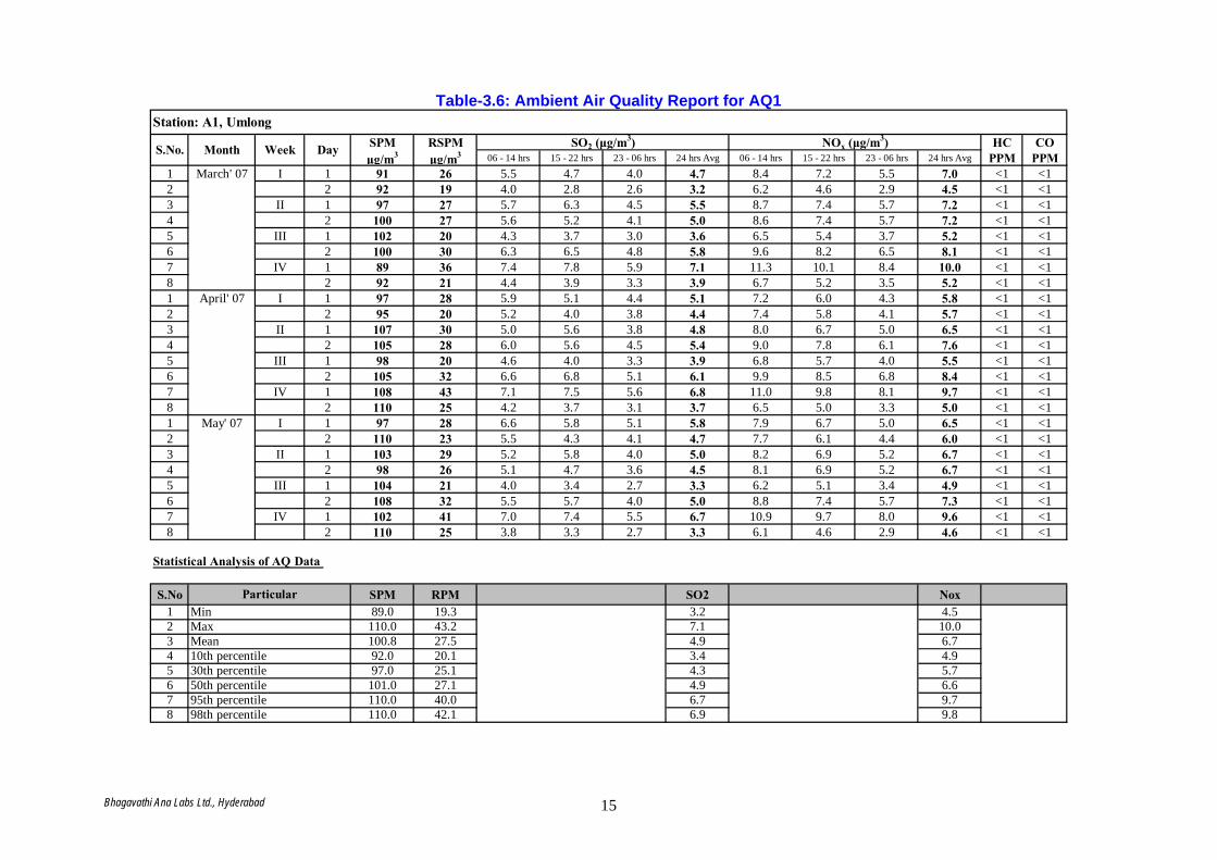
Table-3.6: Ambient Air Quality Report for AQ1
SPM RSPM HC COμg/m3 μg/m3 06 - 14 hrs 15 - 22 hrs 23 - 06 hrs 24 hrs Avg 06 - 14 hrs 15 - 22 hrs 23 - 06 hrs 24 hrs Avg PPM PPM
1 March' 07 I 1 91 26 5.5 4.7 4.0 4.7 8.4 7.2 5.5 7.0 <1 <12 2 92 19 4.0 2.8 2.6 3.2 6.2 4.6 2.9 4.5 <1 <13 II 1 97 27 5.7 6.3 4.5 5.5 8.7 7.4 5.7 7.2 <1 <14 2 100 27 5.6 5.2 4.1 5.0 8.6 7.4 5.7 7.2 <1 <15 III 1 102 20 4.3 3.7 3.0 3.6 6.5 5.4 3.7 5.2 <1 <16 2 100 30 6.3 6.5 4.8 5.8 9.6 8.2 6.5 8.1 <1 <17 IV 1 89 36 7.4 7.8 5.9 7.1 11.3 10.1 8.4 10.0 <1 <18 2 92 21 4.4 3.9 3.3 3.9 6.7 5.2 3.5 5.2 <1 <11 April' 07 I 1 97 28 5.9 5.1 4.4 5.1 7.2 6.0 4.3 5.8 <1 <12 2 95 20 5.2 4.0 3.8 4.4 7.4 5.8 4.1 5.7 <1 <13 II 1 107 30 5.0 5.6 3.8 4.8 8.0 6.7 5.0 6.5 <1 <14 2 105 28 6.0 5.6 4.5 5.4 9.0 7.8 6.1 7.6 <1 <15 III 1 98 20 4.6 4.0 3.3 3.9 6.8 5.7 4.0 5.5 <1 <16 2 105 32 6.6 6.8 5.1 6.1 9.9 8.5 6.8 8.4 <1 <17 IV 1 108 43 7.1 7.5 5.6 6.8 11.0 9.8 8.1 9.7 <1 <18 2 110 25 4.2 3.7 3.1 3.7 6.5 5.0 3.3 5.0 <1 <11 May' 07 I 1 97 28 6.6 5.8 5.1 5.8 7.9 6.7 5.0 6.5 <1 <12 2 110 23 5.5 4.3 4.1 4.7 7.7 6.1 4.4 6.0 <1 <13 II 1 103 29 5.2 5.8 4.0 5.0 8.2 6.9 5.2 6.7 <1 <14 2 98 26 5.1 4.7 3.6 4.5 8.1 6.9 5.2 6.7 <1 <15 III 1 104 21 4.0 3.4 2.7 3.3 6.2 5.1 3.4 4.9 <1 <16 2 108 32 5.5 5.7 4.0 5.0 8.8 7.4 5.7 7.3 <1 <17 IV 1 102 41 7.0 7.4 5.5 6.7 10.9 9.7 8.0 9.6 <1 <18 2 110 25 3.8 3.3 2.7 3.3 6.1 4.6 2.9 4.6 <1 <1
S.No SPM RPM SO2 Nox1 89.0 19.3 3.2 4.52 110.0 43.2 7.1 10.03 100.8 27.5 4.9 6.74 92.0 20.1 3.4 4.95 97.0 25.1 4.3 5.76 101.0 27.1 4.9 6.67 110.0 40.0 6.7 9.78 110.0 42.1 6.9 9.8
SO2 (μg/m3) NOx (μg/m3)Month Week DayS.No.
Min
98th percentile
Station: A1, Umlong
Statistical Analysis of AQ Data
Particular
MaxMean10th percentile30th percentile50th percentile95th percentile
Bhagavathi Ana Labs Ltd., Hyderabad 15
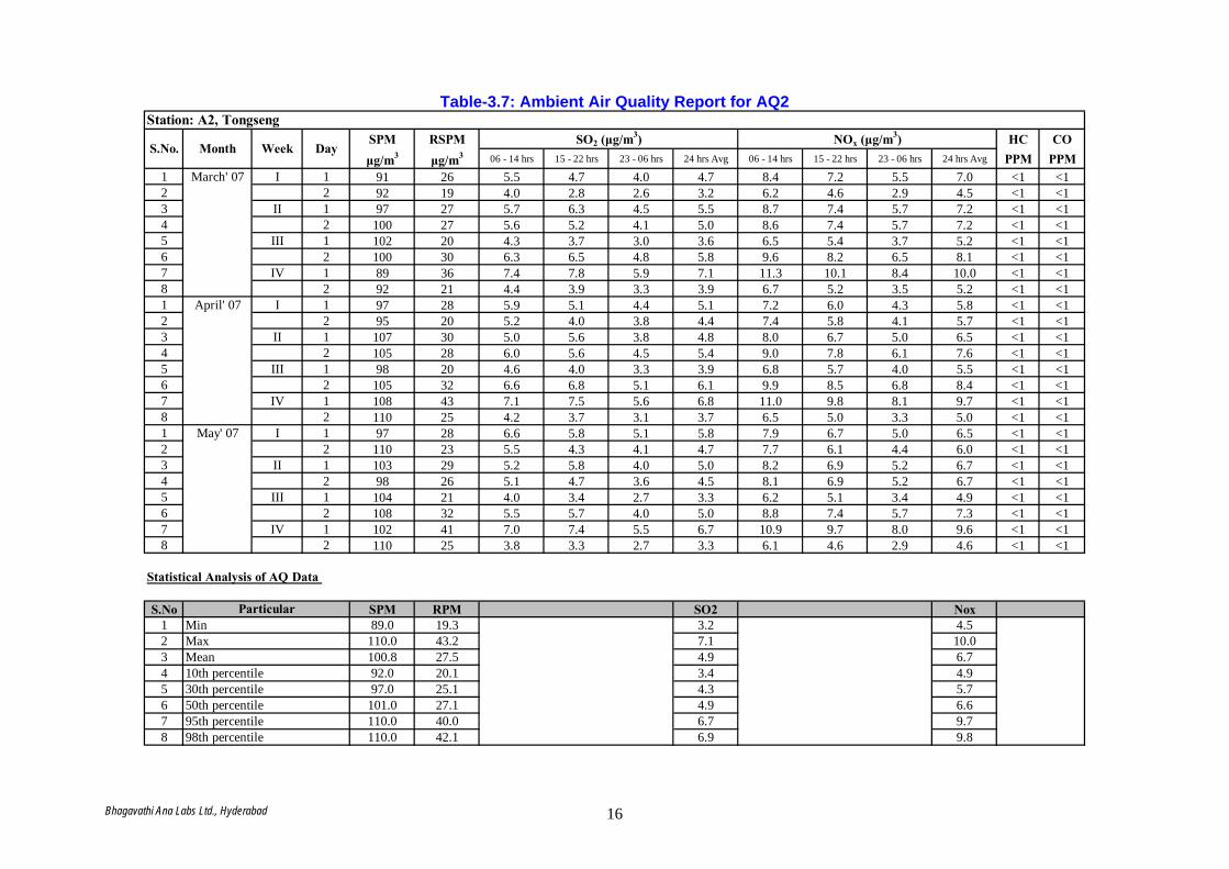
Table-3.7: Ambient Air Quality Report for AQ2
SPM RSPM HC COμg/m3 μg/m3 06 - 14 hrs 15 - 22 hrs 23 - 06 hrs 24 hrs Avg 06 - 14 hrs 15 - 22 hrs 23 - 06 hrs 24 hrs Avg PPM PPM
1 March' 07 I 1 91 26 5.5 4.7 4.0 4.7 8.4 7.2 5.5 7.0 <1 <12 2 92 19 4.0 2.8 2.6 3.2 6.2 4.6 2.9 4.5 <1 <13 II 1 97 27 5.7 6.3 4.5 5.5 8.7 7.4 5.7 7.2 <1 <14 2 100 27 5.6 5.2 4.1 5.0 8.6 7.4 5.7 7.2 <1 <15 III 1 102 20 4.3 3.7 3.0 3.6 6.5 5.4 3.7 5.2 <1 <16 2 100 30 6.3 6.5 4.8 5.8 9.6 8.2 6.5 8.1 <1 <17 IV 1 89 36 7.4 7.8 5.9 7.1 11.3 10.1 8.4 10.0 <1 <18 2 92 21 4.4 3.9 3.3 3.9 6.7 5.2 3.5 5.2 <1 <11 April' 07 I 1 97 28 5.9 5.1 4.4 5.1 7.2 6.0 4.3 5.8 <1 <12 2 95 20 5.2 4.0 3.8 4.4 7.4 5.8 4.1 5.7 <1 <13 II 1 107 30 5.0 5.6 3.8 4.8 8.0 6.7 5.0 6.5 <1 <14 2 105 28 6.0 5.6 4.5 5.4 9.0 7.8 6.1 7.6 <1 <15 III 1 98 20 4.6 4.0 3.3 3.9 6.8 5.7 4.0 5.5 <1 <16 2 105 32 6.6 6.8 5.1 6.1 9.9 8.5 6.8 8.4 <1 <17 IV 1 108 43 7.1 7.5 5.6 6.8 11.0 9.8 8.1 9.7 <1 <18 2 110 25 4.2 3.7 3.1 3.7 6.5 5.0 3.3 5.0 <1 <11 May' 07 I 1 97 28 6.6 5.8 5.1 5.8 7.9 6.7 5.0 6.5 <1 <12 2 110 23 5.5 4.3 4.1 4.7 7.7 6.1 4.4 6.0 <1 <13 II 1 103 29 5.2 5.8 4.0 5.0 8.2 6.9 5.2 6.7 <1 <14 2 98 26 5.1 4.7 3.6 4.5 8.1 6.9 5.2 6.7 <1 <15 III 1 104 21 4.0 3.4 2.7 3.3 6.2 5.1 3.4 4.9 <1 <16 2 108 32 5.5 5.7 4.0 5.0 8.8 7.4 5.7 7.3 <1 <17 IV 1 102 41 7.0 7.4 5.5 6.7 10.9 9.7 8.0 9.6 <1 <18 2 110 25 3.8 3.3 2.7 3.3 6.1 4.6 2.9 4.6 <1 <1
S.No SPM RPM SO2 Nox1 89.0 19.3 3.2 4.52 110.0 43.2 7.1 10.03 100.8 27.5 4.9 6.74 92.0 20.1 3.4 4.95 97.0 25.1 4.3 5.76 101.0 27.1 4.9 6.67 110.0 40.0 6.7 9.78 110.0 42.1 6.9 9.8
Station: A2, Tongseng
S.No. Month Week DaySO2 (μg/m3) NOx (μg/m3)
Statistical Analysis of AQ Data
ParticularMinMaxMean10th percentile30th percentile50th percentile95th percentile98th percentile
Bhagavathi Ana Labs Ltd., Hyderabad 16

Table-3.8: Ambient Air Quality Report for AQ3
SPM RSPM HC COμg/m3 μg/m3 06 - 14 hrs 15 - 22 hrs 23 - 06 hrs 24 hrs Avg 06 - 14 hrs 15 - 22 hrs 23 - 06 hrs 24 hrs Avg PPM PPM
1 March' 07 I 1 87 25 5.3 4.5 3.8 4.5 8.0 6.8 5.1 6.7 <1 <12 2 90 19 5.9 4.7 4.5 5.0 9.0 7.4 5.7 7.4 <1 <13 II 1 92 26 5.4 6.0 4.2 5.2 8.2 6.9 5.2 6.8 <1 <14 2 98 26 5.5 5.1 4.0 4.9 8.4 7.2 5.5 7.1 <1 <15 III 1 100 20 4.2 3.6 2.9 3.5 6.4 5.3 3.6 5.1 <1 <16 2 107 32 6.7 6.9 5.2 6.3 10.2 8.8 7.1 8.7 <1 <17 IV 1 102 41 8.5 8.9 7.0 8.1 13.0 11.8 10.1 11.6 <1 <18 2 100 23 7.2 6.7 6.1 6.7 11.0 9.5 7.8 9.4 <1 <11 April' 07 I 1 105 30 6.3 5.5 4.8 5.6 6.8 5.6 3.9 5.5 <1 <12 2 98 21 7.1 5.9 5.7 6.2 10.2 8.6 6.9 8.6 <1 <13 II 1 102 29 4.7 5.3 3.5 4.5 7.5 6.2 4.5 6.1 <1 <14 2 100 27 5.9 5.5 4.4 5.3 8.8 7.6 5.9 7.5 <1 <15 III 1 96 19 5.0 4.4 3.7 4.3 6.7 5.6 3.9 5.4 <1 <16 2 105 32 7.0 7.2 5.5 6.6 10.5 9.1 7.4 9.0 <1 <17 IV 1 108 43 8.2 8.6 6.7 7.8 12.7 11.5 9.8 11.3 <1 <18 2 102 23 7.0 6.5 5.9 6.5 10.8 9.3 7.6 9.2 <1 <11 May' 07 I 1 106 31 7.0 6.2 5.5 6.3 7.5 6.3 4.6 6.2 <1 <12 2 98 21 7.4 6.2 6.0 6.5 10.5 8.9 7.2 8.9 <1 <13 II 1 100 28 4.9 5.5 3.7 4.7 7.7 6.4 4.7 6.3 <1 <14 2 103 28 5.0 4.6 3.5 4.4 7.9 6.7 5.0 6.6 <1 <15 III 1 102 20 4.8 4.2 3.5 4.1 6.1 5.0 3.3 4.8 <1 <16 2 97 29 5.9 6.1 4.4 5.5 9.4 8.0 6.3 7.9 <1 <17 IV 1 106 42 8.1 8.5 6.6 7.7 12.6 11.4 9.7 11.2 <1 <18 2 100 23 6.6 6.1 5.5 6.1 10.4 8.9 7.2 8.8 <1 <1
S.No SPM RPM SO2 Nox1 87.0 18.9 3.5 4.82 108.0 43.2 8.1 11.63 100.2 27.4 5.7 7.84 93.2 20.1 4.3 5.45 98.0 23.0 4.9 6.56 100.0 26.7 5.5 7.47 106.9 42.2 7.8 11.38 107.5 42.8 8.0 11.5
Station: A3, Sonapur
S.No. Month Week DaySO2 (μg/m3) NOx (μg/m3)
Statistical Analysis of AQ Data
ParticularMinMaxMean10th percentile30th percentile50th percentile95th percentile98th percentile
Bhagavathi Ana Labs Ltd., Hyderabad 17
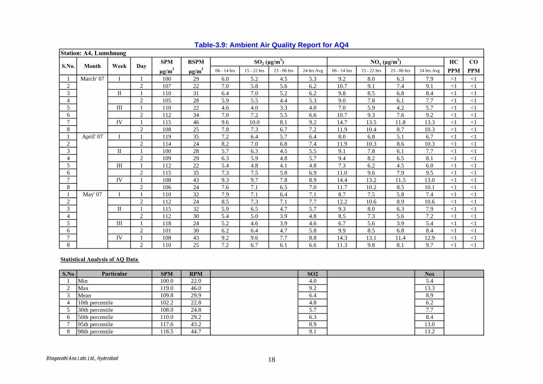
Table-3.9: Ambient Air Quality Report for AQ4
SPM RSPM HC COμg/m3 μg/m3 06 - 14 hrs 15 - 22 hrs 23 - 06 hrs 24 hrs Avg 06 - 14 hrs 15 - 22 hrs 23 - 06 hrs 24 hrs Avg PPM PPM
1 March' 07 I 1 100 29 6.0 5.2 4.5 5.3 9.2 8.0 6.3 7.9 <1 <12 2 107 22 7.0 5.8 5.6 6.2 10.7 9.1 7.4 9.1 <1 <13 II 1 110 31 6.4 7.0 5.2 6.2 9.8 8.5 6.8 8.4 <1 <14 2 105 28 5.9 5.5 4.4 5.3 9.0 7.8 6.1 7.7 <1 <15 III 1 110 22 4.6 4.0 3.3 4.0 7.0 5.9 4.2 5.7 <1 <16 2 112 34 7.0 7.2 5.5 6.6 10.7 9.3 7.6 9.2 <1 <17 IV 1 115 46 9.6 10.0 8.1 9.2 14.7 13.5 11.8 13.3 <1 <18 2 108 25 7.8 7.3 6.7 7.2 11.9 10.4 8.7 10.3 <1 <11 April' 07 I 1 119 35 7.2 6.4 5.7 6.4 8.0 6.8 5.1 6.7 <1 <12 2 114 24 8.2 7.0 6.8 7.4 11.9 10.3 8.6 10.3 <1 <13 II 1 100 28 5.7 6.3 4.5 5.5 9.1 7.8 6.1 7.7 <1 <14 2 109 29 6.3 5.9 4.8 5.7 9.4 8.2 6.5 8.1 <1 <15 III 1 112 22 5.4 4.8 4.1 4.8 7.3 6.2 4.5 6.0 <1 <16 2 115 35 7.3 7.5 5.8 6.9 11.0 9.6 7.9 9.5 <1 <17 IV 1 108 43 9.3 9.7 7.8 8.9 14.4 13.2 11.5 13.0 <1 <18 2 106 24 7.6 7.1 6.5 7.0 11.7 10.2 8.5 10.1 <1 <11 May' 07 I 1 110 32 7.9 7.1 6.4 7.1 8.7 7.5 5.8 7.4 <1 <12 2 112 24 8.5 7.3 7.1 7.7 12.2 10.6 8.9 10.6 <1 <13 II 1 115 32 5.9 6.5 4.7 5.7 9.3 8.0 6.3 7.9 <1 <14 2 112 30 5.4 5.0 3.9 4.8 8.5 7.3 5.6 7.2 <1 <15 III 1 118 24 5.2 4.6 3.9 4.6 6.7 5.6 3.9 5.4 <1 <16 2 101 30 6.2 6.4 4.7 5.8 9.9 8.5 6.8 8.4 <1 <17 IV 1 108 43 9.2 9.6 7.7 8.8 14.3 13.1 11.4 12.9 <1 <18 2 110 25 7.2 6.7 6.1 6.6 11.3 9.8 8.1 9.7 <1 <1
S.No SPM RPM SO2 Nox1 100.0 22.0 4.0 5.42 119.0 46.0 9.2 13.33 109.8 29.9 6.4 8.94 102.2 22.8 4.8 6.25 108.0 24.8 5.7 7.76 110.0 29.2 6.3 8.47 117.6 43.2 8.9 13.08 118.5 44.7 9.1 13.2
Station: A4, Lumshnung
S.No. Month Week DaySO2 (μg/m3) NOx (μg/m3)
Statistical Analysis of AQ Data
ParticularMinMaxMean10th percentile30th percentile50th percentile95th percentile98th percentile
Bhagavathi Ana Labs Ltd., Hyderabad 18
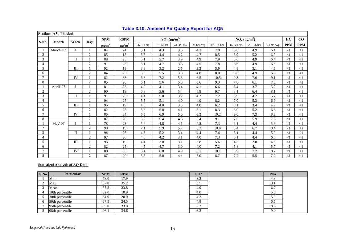
Table-3.10: Ambient Air Quality Report for AQ5
SPM RSPM HC COμg/m3 μg/m3 06 - 14 hrs 15 - 22 hrs 23 - 06 hrs 24 hrs Avg 06 - 14 hrs 15 - 22 hrs 23 - 06 hrs 24 hrs Avg PPM PPM
1 March' 07 I 1 84 24 5.1 4.3 3.6 4.3 7.8 6.6 4.9 6.4 <1 <12 2 85 18 5.6 4.4 4.2 4.7 8.5 6.9 5.2 6.9 <1 <13 II 1 88 25 5.1 5.7 3.9 4.9 7.9 6.6 4.9 6.4 <1 <14 2 91 25 5.1 4.7 3.6 4.5 7.8 6.6 4.9 6.5 <1 <15 III 1 92 18 3.8 3.2 2.5 3.2 5.9 4.8 3.1 4.6 <1 <16 2 84 25 5.3 5.5 3.8 4.8 8.0 6.6 4.9 6.5 <1 <17 IV 1 82 33 6.8 7.2 5.3 6.5 10.5 9.3 7.6 9.1 <1 <18 2 85 20 6.1 5.6 5.0 5.6 9.3 7.8 6.1 7.8 <1 <11 April' 07 I 1 81 23 4.9 4.1 3.4 4.1 6.6 5.4 3.7 5.2 <1 <12 2 90 19 6.8 5.6 5.4 5.9 9.7 8.1 6.4 8.1 <1 <13 II 1 91 25 4.4 5.0 3.2 4.2 7.2 5.9 4.2 5.7 <1 <14 2 94 25 5.5 5.1 4.0 4.9 8.2 7.0 5.3 6.9 <1 <15 III 1 95 19 4.6 4.0 3.3 4.0 6.2 5.1 3.4 4.9 <1 <16 2 82 25 5.6 5.8 4.1 5.1 8.3 6.9 5.2 6.8 <1 <17 IV 1 85 34 6.5 6.9 5.0 6.2 10.2 9.0 7.3 8.8 <1 <18 2 87 20 5.9 5.4 4.8 5.4 9.1 7.6 5.9 7.6 <1 <11 May' 07 I 1 78 23 5.6 4.8 4.1 4.8 7.3 6.1 4.4 5.9 <1 <12 2 90 19 7.1 5.9 5.7 6.2 10.0 8.4 6.7 8.4 <1 <13 II 1 94 26 4.6 5.2 3.4 4.4 7.4 6.1 4.4 5.9 <1 <14 2 97 26 4.6 4.2 3.1 4.0 7.3 6.1 4.4 6.0 <1 <15 III 1 95 19 4.4 3.8 3.1 3.8 5.6 4.5 2.8 4.3 <1 <16 2 82 25 4.5 4.7 3.0 4.0 7.2 5.8 4.1 5.7 <1 <17 IV 1 88 35 6.4 6.8 4.9 6.1 10.1 8.9 7.2 8.7 <1 <18 2 87 20 5.5 5.0 4.4 5.0 8.7 7.2 5.5 7.2 <1 <1
S.No SPM RPM SO2 Nox1 78.0 17.9 3.2 4.32 97.0 35.2 6.5 9.13 87.8 23.8 4.9 6.74 82.0 18.9 4.0 5.05 84.9 20.0 4.3 5.96 87.5 24.5 4.8 6.57 95.0 33.8 6.2 8.88 96.1 34.6 6.3 9.0
Station: A5, Thaskai
S.No. Month Week DaySO2 (μg/m3) NOx (μg/m3)
Statistical Analysis of AQ Data
ParticularMinMaxMean10th percentile30th percentile50th percentile95th percentile98th percentile
Bhagavathi Ana Labs Ltd., Hyderabad 15
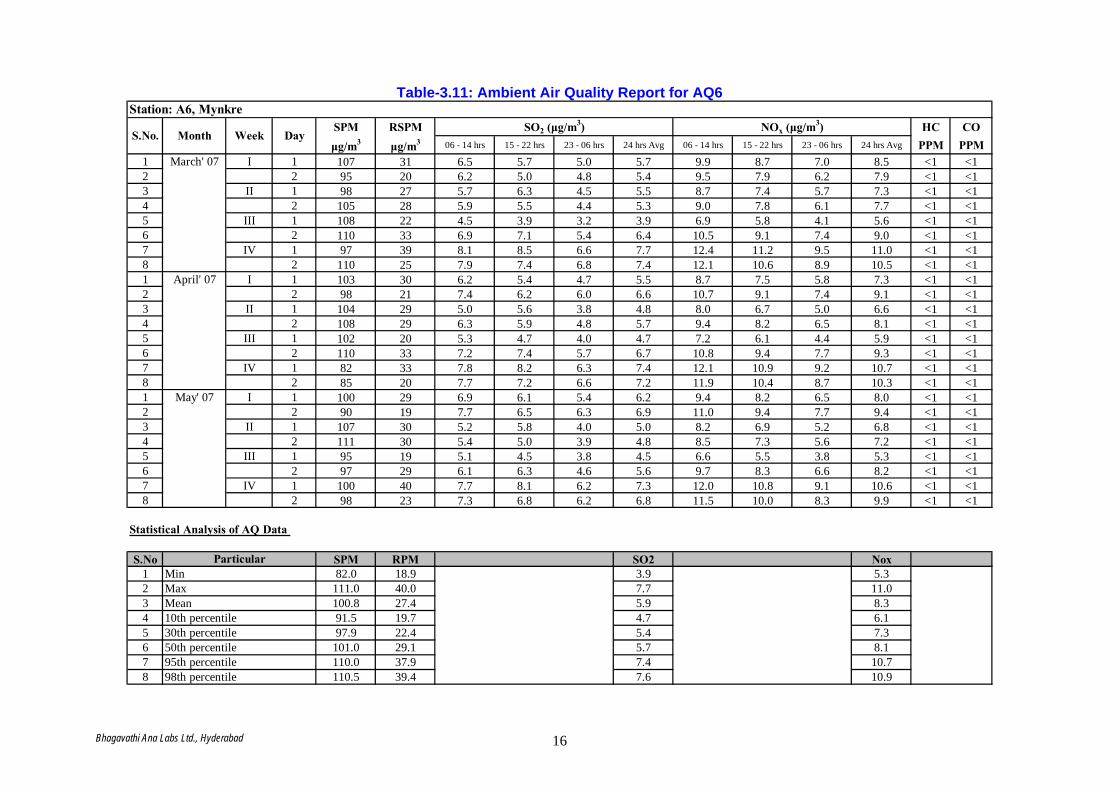
Table-3.11: Ambient Air Quality Report for AQ6
SPM RSPM HC COμg/m3 μg/m3 06 - 14 hrs 15 - 22 hrs 23 - 06 hrs 24 hrs Avg 06 - 14 hrs 15 - 22 hrs 23 - 06 hrs 24 hrs Avg PPM PPM
1 March' 07 I 1 107 31 6.5 5.7 5.0 5.7 9.9 8.7 7.0 8.5 <1 <12 2 95 20 6.2 5.0 4.8 5.4 9.5 7.9 6.2 7.9 <1 <13 II 1 98 27 5.7 6.3 4.5 5.5 8.7 7.4 5.7 7.3 <1 <14 2 105 28 5.9 5.5 4.4 5.3 9.0 7.8 6.1 7.7 <1 <15 III 1 108 22 4.5 3.9 3.2 3.9 6.9 5.8 4.1 5.6 <1 <16 2 110 33 6.9 7.1 5.4 6.4 10.5 9.1 7.4 9.0 <1 <17 IV 1 97 39 8.1 8.5 6.6 7.7 12.4 11.2 9.5 11.0 <1 <18 2 110 25 7.9 7.4 6.8 7.4 12.1 10.6 8.9 10.5 <1 <11 April' 07 I 1 103 30 6.2 5.4 4.7 5.5 8.7 7.5 5.8 7.3 <1 <12 2 98 21 7.4 6.2 6.0 6.6 10.7 9.1 7.4 9.1 <1 <13 II 1 104 29 5.0 5.6 3.8 4.8 8.0 6.7 5.0 6.6 <1 <14 2 108 29 6.3 5.9 4.8 5.7 9.4 8.2 6.5 8.1 <1 <15 III 1 102 20 5.3 4.7 4.0 4.7 7.2 6.1 4.4 5.9 <1 <16 2 110 33 7.2 7.4 5.7 6.7 10.8 9.4 7.7 9.3 <1 <17 IV 1 82 33 7.8 8.2 6.3 7.4 12.1 10.9 9.2 10.7 <1 <18 2 85 20 7.7 7.2 6.6 7.2 11.9 10.4 8.7 10.3 <1 <11 May' 07 I 1 100 29 6.9 6.1 5.4 6.2 9.4 8.2 6.5 8.0 <1 <12 2 90 19 7.7 6.5 6.3 6.9 11.0 9.4 7.7 9.4 <1 <13 II 1 107 30 5.2 5.8 4.0 5.0 8.2 6.9 5.2 6.8 <1 <14 2 111 30 5.4 5.0 3.9 4.8 8.5 7.3 5.6 7.2 <1 <15 III 1 95 19 5.1 4.5 3.8 4.5 6.6 5.5 3.8 5.3 <1 <16 2 97 29 6.1 6.3 4.6 5.6 9.7 8.3 6.6 8.2 <1 <17 IV 1 100 40 7.7 8.1 6.2 7.3 12.0 10.8 9.1 10.6 <1 <18 2 98 23 7.3 6.8 6.2 6.8 11.5 10.0 8.3 9.9 <1 <1
S.No SPM RPM SO2 Nox1 82.0 18.9 3.9 5.32 111.0 40.0 7.7 11.03 100.8 27.4 5.9 8.34 91.5 19.7 4.7 6.15 97.9 22.4 5.4 7.36 101.0 29.1 5.7 8.17 110.0 37.9 7.4 10.78 110.5 39.4 7.6 10.9
Station: A6, Mynkre
S.No. Month Week DaySO2 (μg/m3) NOx (μg/m3)
Statistical Analysis of AQ Data
ParticularMinMaxMean10th percentile30th percentile50th percentile95th percentile98th percentile
Bhagavathi Ana Labs Ltd., Hyderabad 16
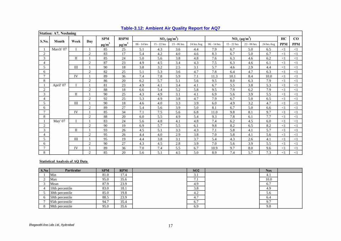
Table-3.12: Ambient Air Quality Report for AQ7
SPM RSPM HC COμg/m3 μg/m3 06 - 14 hrs 15 - 22 hrs 23 - 06 hrs 24 hrs Avg 06 - 14 hrs 15 - 22 hrs 23 - 06 hrs 24 hrs Avg PPM PPM
1 March' 07 I 1 85 25 5.1 4.3 3.6 4.4 7.9 6.7 5.0 6.5 <1 <12 2 83 17 5.4 4.2 4.0 4.6 8.3 6.7 5.0 6.7 <1 <13 II 1 85 24 5.0 5.6 3.8 4.8 7.6 6.3 4.6 6.2 <1 <14 2 87 23 4.9 4.5 3.4 4.3 7.5 6.3 4.6 6.1 <1 <15 III 1 90 18 3.8 3.2 2.5 3.1 5.7 4.6 2.9 4.4 <1 <16 2 82 25 5.1 5.3 3.6 4.7 7.8 6.4 4.7 6.3 <1 <17 IV 1 89 36 7.4 7.8 5.9 7.1 11.3 10.1 8.4 10.0 <1 <18 2 86 20 6.2 5.7 5.1 5.6 9.5 8.0 6.3 7.9 <1 <11 April' 07 I 1 81 23 4.9 4.1 3.4 4.1 6.7 5.5 3.8 5.3 <1 <12 2 88 18 6.6 5.4 5.2 5.8 9.5 7.9 6.2 7.9 <1 <13 II 1 90 25 4.3 4.9 3.1 4.1 6.9 5.6 3.9 5.5 <1 <14 2 92 25 5.3 4.9 3.8 4.7 7.9 6.7 5.0 6.5 <1 <15 III 1 90 18 4.6 4.0 3.3 3.9 6.0 4.9 3.2 4.7 <1 <16 2 89 27 5.4 5.6 3.9 5.0 8.1 6.7 5.0 6.6 <1 <17 IV 1 85 34 7.1 7.5 5.6 6.8 11.0 9.8 8.1 9.7 <1 <18 2 88 20 6.0 5.5 4.9 5.4 9.3 7.8 6.1 7.7 <1 <11 May' 07 I 1 83 24 5.6 4.8 4.1 4.8 7.4 6.2 4.5 6.0 <1 <12 2 90 19 6.9 5.7 5.5 6.1 9.8 8.2 6.5 8.2 <1 <13 II 1 93 26 4.5 5.1 3.3 4.3 7.1 5.8 4.1 5.7 <1 <14 2 95 26 4.4 4.0 2.9 3.8 7.0 5.8 4.1 5.6 <1 <15 III 1 95 19 4.4 3.8 3.1 3.7 5.4 4.3 2.6 4.1 <1 <16 2 90 27 4.3 4.5 2.8 3.9 7.0 5.6 3.9 5.5 <1 <17 IV 1 89 36 7.0 7.4 5.5 6.7 10.9 9.7 8.0 9.6 <1 <18 2 85 20 5.6 5.1 4.5 5.0 8.9 7.4 5.7 7.3 <1 <1
S.No SPM RPM SO2 Nox1 81.0 17.4 3.1 4.12 95.0 35.6 7.1 10.03 87.9 23.9 4.9 6.74 83.0 18.1 3.8 4.95 85.0 19.8 4.2 5.66 88.5 23.9 4.7 6.47 94.7 35.4 6.7 9.78 95.0 35.6 6.9 9.8
Station: A7, Noshning
S.No. Month Week DaySO2 (μg/m3) NOx (μg/m3)
Statistical Analysis of AQ Data
ParticularMinMaxMean10th percentile30th percentile50th percentile95th percentile98th percentile
Bhagavathi Ana Labs Ltd., Hyderabad 17
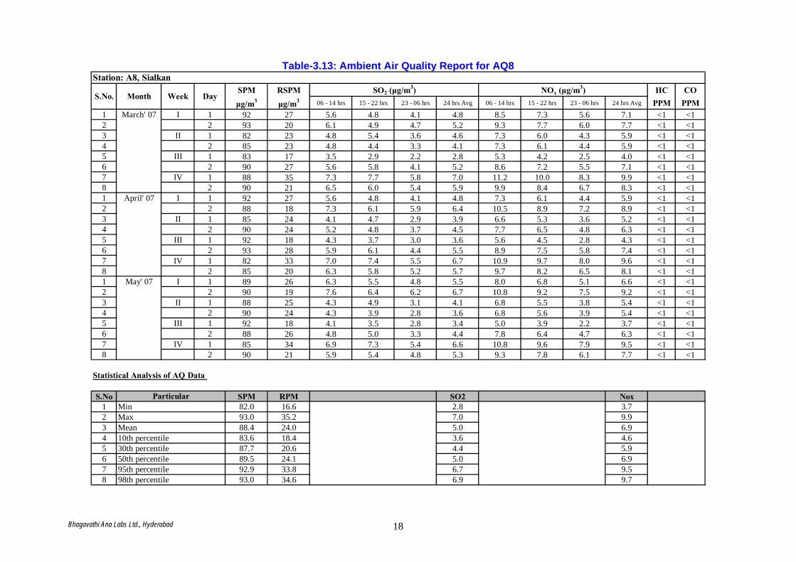
Table-3.13: Ambient Air Quality Report for AQ8
SPM RSPM HC COμg/m3 μg/m3 06 - 14 hrs 15 - 22 hrs 23 - 06 hrs 24 hrs Avg 06 - 14 hrs 15 - 22 hrs 23 - 06 hrs 24 hrs Avg PPM PPM
1 March' 07 I 1 92 27 5.6 4.8 4.1 4.8 8.5 7.3 5.6 7.1 <1 <12 2 93 20 6.1 4.9 4.7 5.2 9.3 7.7 6.0 7.7 <1 <13 II 1 82 23 4.8 5.4 3.6 4.6 7.3 6.0 4.3 5.9 <1 <14 2 85 23 4.8 4.4 3.3 4.1 7.3 6.1 4.4 5.9 <1 <15 III 1 83 17 3.5 2.9 2.2 2.8 5.3 4.2 2.5 4.0 <1 <16 2 90 27 5.6 5.8 4.1 5.2 8.6 7.2 5.5 7.1 <1 <17 IV 1 88 35 7.3 7.7 5.8 7.0 11.2 10.0 8.3 9.9 <1 <18 2 90 21 6.5 6.0 5.4 5.9 9.9 8.4 6.7 8.3 <1 <11 April' 07 I 1 92 27 5.6 4.8 4.1 4.8 7.3 6.1 4.4 5.9 <1 <12 2 88 18 7.3 6.1 5.9 6.4 10.5 8.9 7.2 8.9 <1 <13 II 1 85 24 4.1 4.7 2.9 3.9 6.6 5.3 3.6 5.2 <1 <14 2 90 24 5.2 4.8 3.7 4.5 7.7 6.5 4.8 6.3 <1 <15 III 1 92 18 4.3 3.7 3.0 3.6 5.6 4.5 2.8 4.3 <1 <16 2 93 28 5.9 6.1 4.4 5.5 8.9 7.5 5.8 7.4 <1 <17 IV 1 82 33 7.0 7.4 5.5 6.7 10.9 9.7 8.0 9.6 <1 <18 2 85 20 6.3 5.8 5.2 5.7 9.7 8.2 6.5 8.1 <1 <11 May' 07 I 1 89 26 6.3 5.5 4.8 5.5 8.0 6.8 5.1 6.6 <1 <12 2 90 19 7.6 6.4 6.2 6.7 10.8 9.2 7.5 9.2 <1 <13 II 1 88 25 4.3 4.9 3.1 4.1 6.8 5.5 3.8 5.4 <1 <14 2 90 24 4.3 3.9 2.8 3.6 6.8 5.6 3.9 5.4 <1 <15 III 1 92 18 4.1 3.5 2.8 3.4 5.0 3.9 2.2 3.7 <1 <16 2 88 26 4.8 5.0 3.3 4.4 7.8 6.4 4.7 6.3 <1 <17 IV 1 85 34 6.9 7.3 5.4 6.6 10.8 9.6 7.9 9.5 <1 <18 2 90 21 5.9 5.4 4.8 5.3 9.3 7.8 6.1 7.7 <1 <1
S.No SPM RPM SO2 Nox1 82.0 16.6 2.8 3.72 93.0 35.2 7.0 9.93 88.4 24.0 5.0 6.94 83.6 18.4 3.6 4.65 87.7 20.6 4.4 5.96 89.5 24.1 5.0 6.97 92.9 33.8 6.7 9.58 93.0 34.6 6.9 9.7
Station: A8, Sialkan
S.No. Month Week DaySO2 (μg/m3) NOx (μg/m3)
Statistical Analysis of AQ Data
ParticularMinMaxMean10th percentile30th percentile50th percentile95th percentile98th percentile
Bhagavathi Ana Labs Ltd., Hyderabad 18

Bhagavathi Ana Labs Ltd., Hyderabad 19
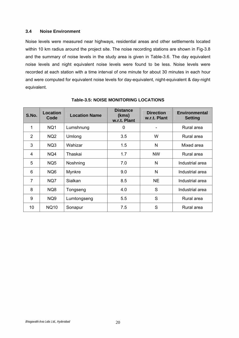
3.4 Noise Environment Noise levels were measured near highways, residential areas and other settlements located
within 10 km radius around the project site. The noise recording stations are shown in Fig-3.8
and the summary of noise levels in the study area is given in Table-3.6. The day equivalent
noise levels and night equivalent noise levels were found to be less. Noise levels were
recorded at each station with a time interval of one minute for about 30 minutes in each hour
and were computed for equivalent noise levels for day-equivalent, night-equivalent & day-night
equivalent.
Table-3.5: NOISE MONITORING LOCATIONS
S.No. Location Code Location Name
Distance (kms)
w.r.t. Plant Direction
w.r.t. Plant Environmental
Setting
1 NQ1 Lumshnung 0 - Rural area
2 NQ2 Umlong 3.5 W Rural area
3 NQ3 Wahizar 1.5 N Mixed area
4 NQ4 Thaskai 1.7 NW Rural area
5 NQ5 Noshning 7.0 N Industrial area
6 NQ6 Mynkre 9.0 N Industrial area
7 NQ7 Sialkan 8.5 NE Industrial area
8 NQ8 Tongseng 4.0 S Industrial area
9 NQ9 Lumtongseng 5.5 S Rural area
10 NQ10 Sonapur 7.5 S Rural area
Bhagavathi Ana Labs Ltd., Hyderabad 20

Fig-3.8: Map showing Noise Monitoring Locations
Bhagavathi Ana Labs Ltd., Hyderabad 21
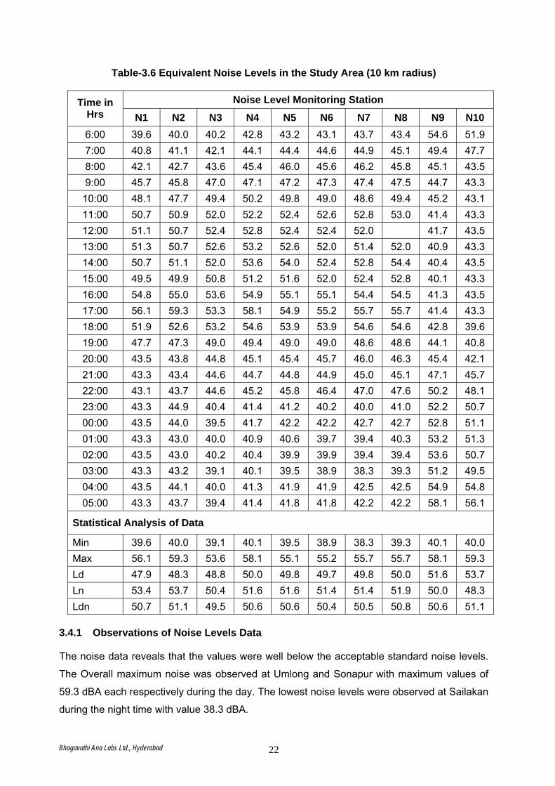
Table-3.6 Equivalent Noise Levels in the Study Area (10 km radius)
Noise Level Monitoring Station Time in Hrs N1 N2 N3 N4 N5 N6 N7 N8 N9 N10 6:00 39.6 40.0 40.2 42.8 43.2 43.1 43.7 43.4 54.6 51.9 7:00 40.8 41.1 42.1 44.1 44.4 44.6 44.9 45.1 49.4 47.7 8:00 42.1 42.7 43.6 45.4 46.0 45.6 46.2 45.8 45.1 43.5 9:00 45.7 45.8 47.0 47.1 47.2 47.3 47.4 47.5 44.7 43.3
10:00 48.1 47.7 49.4 50.2 49.8 49.0 48.6 49.4 45.2 43.1 11:00 50.7 50.9 52.0 52.2 52.4 52.6 52.8 53.0 41.4 43.3 12:00 51.1 50.7 52.4 52.8 52.4 52.4 52.0 41.7 43.5 13:00 51.3 50.7 52.6 53.2 52.6 52.0 51.4 52.0 40.9 43.3 14:00 50.7 51.1 52.0 53.6 54.0 52.4 52.8 54.4 40.4 43.5 15:00 49.5 49.9 50.8 51.2 51.6 52.0 52.4 52.8 40.1 43.3 16:00 54.8 55.0 53.6 54.9 55.1 55.1 54.4 54.5 41.3 43.5 17:00 56.1 59.3 53.3 58.1 54.9 55.2 55.7 55.7 41.4 43.3 18:00 51.9 52.6 53.2 54.6 53.9 53.9 54.6 54.6 42.8 39.6 19:00 47.7 47.3 49.0 49.4 49.0 49.0 48.6 48.6 44.1 40.8 20:00 43.5 43.8 44.8 45.1 45.4 45.7 46.0 46.3 45.4 42.1 21:00 43.3 43.4 44.6 44.7 44.8 44.9 45.0 45.1 47.1 45.7 22:00 43.1 43.7 44.6 45.2 45.8 46.4 47.0 47.6 50.2 48.1 23:00 43.3 44.9 40.4 41.4 41.2 40.2 40.0 41.0 52.2 50.7 00:00 43.5 44.0 39.5 41.7 42.2 42.2 42.7 42.7 52.8 51.1 01:00 43.3 43.0 40.0 40.9 40.6 39.7 39.4 40.3 53.2 51.3 02:00 43.5 43.0 40.2 40.4 39.9 39.9 39.4 39.4 53.6 50.7 03:00 43.3 43.2 39.1 40.1 39.5 38.9 38.3 39.3 51.2 49.5 04:00 43.5 44.1 40.0 41.3 41.9 41.9 42.5 42.5 54.9 54.8 05:00 43.3 43.7 39.4 41.4 41.8 41.8 42.2 42.2 58.1 56.1
Statistical Analysis of Data
Min 39.6 40.0 39.1 40.1 39.5 38.9 38.3 39.3 40.1 40.0 Max 56.1 59.3 53.6 58.1 55.1 55.2 55.7 55.7 58.1 59.3 Ld 47.9 48.3 48.8 50.0 49.8 49.7 49.8 50.0 51.6 53.7 Ln 53.4 53.7 50.4 51.6 51.6 51.4 51.4 51.9 50.0 48.3 Ldn 50.7 51.1 49.5 50.6 50.6 50.4 50.5 50.8 50.6 51.1
3.4.1 Observations of Noise Levels Data The noise data reveals that the values were well below the acceptable standard noise levels.
The Overall maximum noise was observed at Umlong and Sonapur with maximum values of
59.3 dBA each respectively during the day. The lowest noise levels were observed at Sailakan
during the night time with value 38.3 dBA.
Bhagavathi Ana Labs Ltd., Hyderabad 22
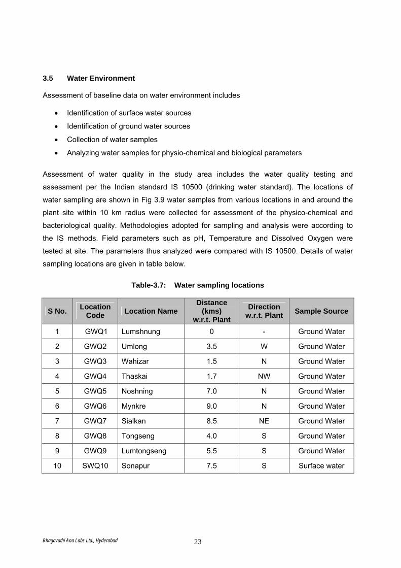
3.5 Water Environment Assessment of baseline data on water environment includes
• Identification of surface water sources
• Identification of ground water sources
• Collection of water samples
• Analyzing water samples for physio-chemical and biological parameters
Assessment of water quality in the study area includes the water quality testing and
assessment per the Indian standard IS 10500 (drinking water standard). The locations of
water sampling are shown in Fig 3.9 water samples from various locations in and around the
plant site within 10 km radius were collected for assessment of the physico-chemical and
bacteriological quality. Methodologies adopted for sampling and analysis were according to
the IS methods. Field parameters such as pH, Temperature and Dissolved Oxygen were
tested at site. The parameters thus analyzed were compared with IS 10500. Details of water
sampling locations are given in table below.
Table-3.7: Water sampling locations
S No. Location Code Location Name
Distance (kms)
w.r.t. Plant Direction
w.r.t. Plant Sample Source
1 GWQ1 Lumshnung 0 - Ground Water
2 GWQ2 Umlong 3.5 W Ground Water
3 GWQ3 Wahizar 1.5 N Ground Water
4 GWQ4 Thaskai 1.7 NW Ground Water
5 GWQ5 Noshning 7.0 N Ground Water
6 GWQ6 Mynkre 9.0 N Ground Water
7 GWQ7 Sialkan 8.5 NE Ground Water
8 GWQ8 Tongseng 4.0 S Ground Water
9 GWQ9 Lumtongseng 5.5 S Ground Water
10 SWQ10 Sonapur 7.5 S Surface water
Bhagavathi Ana Labs Ltd., Hyderabad 23

Fig-3.9: Map showing Water Quality Monitoring Locations
Bhagavathi Ana Labs Ltd., Hyderabad 24
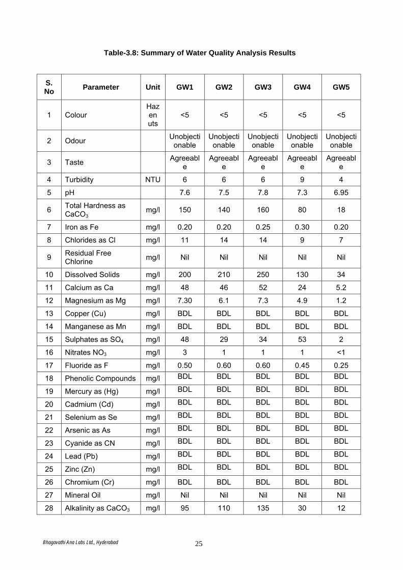
Table-3.8: Summary of Water Quality Analysis Results
S. No Parameter Unit GW1 GW2 GW3 GW4 GW5
1 Colour Hazen uts
<5 <5 <5 <5 <5
2 Odour Unobjectionable
Unobjectionable
Unobjectionable
Unobjectionable
Unobjectionable
3 Taste Agreeable
Agreeable
Agreeable
Agreeable
Agreeable
4 Turbidity NTU 6 6 6 9 4
5 pH 7.6 7.5 7.8 7.3 6.95
6 Total Hardness as CaCO3
mg/l 150 140 160 80 18
7 Iron as Fe mg/l 0.20 0.20 0.25 0.30 0.20
8 Chlorides as Cl mg/l 11 14 14 9 7
9 Residual Free Chlorine mg/l Nil Nil Nil Nil Nil
10 Dissolved Solids mg/l 200 210 250 130 34
11 Calcium as Ca mg/l 48 46 52 24 5.2
12 Magnesium as Mg mg/l 7.30 6.1 7.3 4.9 1.2
13 Copper (Cu) mg/l BDL BDL BDL BDL BDL
14 Manganese as Mn mg/l BDL BDL BDL BDL BDL
15 Sulphates as SO4 mg/l 48 29 34 53 2
16 Nitrates NO3 mg/l 3 1 1 1 <1
17 Fluoride as F mg/l 0.50 0.60 0.60 0.45 0.25
18 Phenolic Compounds mg/l BDL BDL BDL BDL BDL
19 Mercury as (Hg) mg/l BDL BDL BDL BDL BDL
20 Cadmium (Cd) mg/l BDL BDL BDL BDL BDL
21 Selenium as Se mg/l BDL BDL BDL BDL BDL
22 Arsenic as As mg/l BDL BDL BDL BDL BDL
23 Cyanide as CN mg/l BDL BDL BDL BDL BDL
24 Lead (Pb) mg/l BDL BDL BDL BDL BDL
25 Zinc (Zn) mg/l BDL BDL BDL BDL BDL
26 Chromium (Cr) mg/l BDL BDL BDL BDL BDL
27 Mineral Oil mg/l Nil Nil Nil Nil Nil
28 Alkalinity as CaCO3 mg/l 95 110 135 30 12
Bhagavathi Ana Labs Ltd., Hyderabad 25
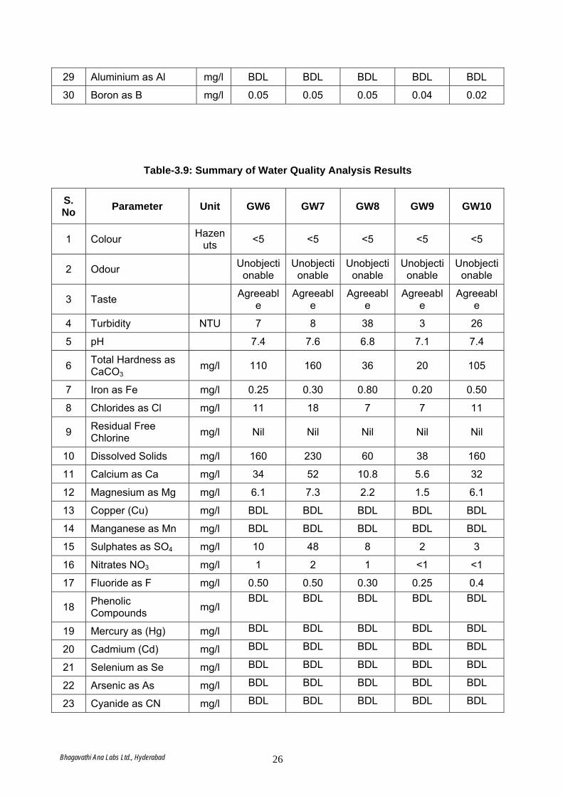
29 Aluminium as Al mg/l BDL BDL BDL BDL BDL
30 Boron as B mg/l 0.05 0.05 0.05 0.04 0.02
Table-3.9: Summary of Water Quality Analysis Results
S. No Parameter Unit GW6 GW7 GW8 GW9 GW10
1 Colour Hazen uts <5 <5 <5 <5 <5
2 Odour Unobjectionable
Unobjectionable
Unobjectionable
Unobjectionable
Unobjectionable
3 Taste Agreeable
Agreeable
Agreeable
Agreeable
Agreeable
4 Turbidity NTU 7 8 38 3 26
5 pH 7.4 7.6 6.8 7.1 7.4
6 Total Hardness as CaCO3
mg/l 110 160 36 20 105
7 Iron as Fe mg/l 0.25 0.30 0.80 0.20 0.50
8 Chlorides as Cl mg/l 11 18 7 7 11
9 Residual Free Chlorine mg/l Nil Nil Nil Nil Nil
10 Dissolved Solids mg/l 160 230 60 38 160
11 Calcium as Ca mg/l 34 52 10.8 5.6 32
12 Magnesium as Mg mg/l 6.1 7.3 2.2 1.5 6.1
13 Copper (Cu) mg/l BDL BDL BDL BDL BDL
14 Manganese as Mn mg/l BDL BDL BDL BDL BDL
15 Sulphates as SO4 mg/l 10 48 8 2 3
16 Nitrates NO3 mg/l 1 2 1 <1 <1
17 Fluoride as F mg/l 0.50 0.50 0.30 0.25 0.4
18 Phenolic Compounds mg/l
BDL BDL BDL BDL BDL
19 Mercury as (Hg) mg/l BDL BDL BDL BDL BDL
20 Cadmium (Cd) mg/l BDL BDL BDL BDL BDL
21 Selenium as Se mg/l BDL BDL BDL BDL BDL
22 Arsenic as As mg/l BDL BDL BDL BDL BDL
23 Cyanide as CN mg/l BDL BDL BDL BDL BDL
Bhagavathi Ana Labs Ltd., Hyderabad 26
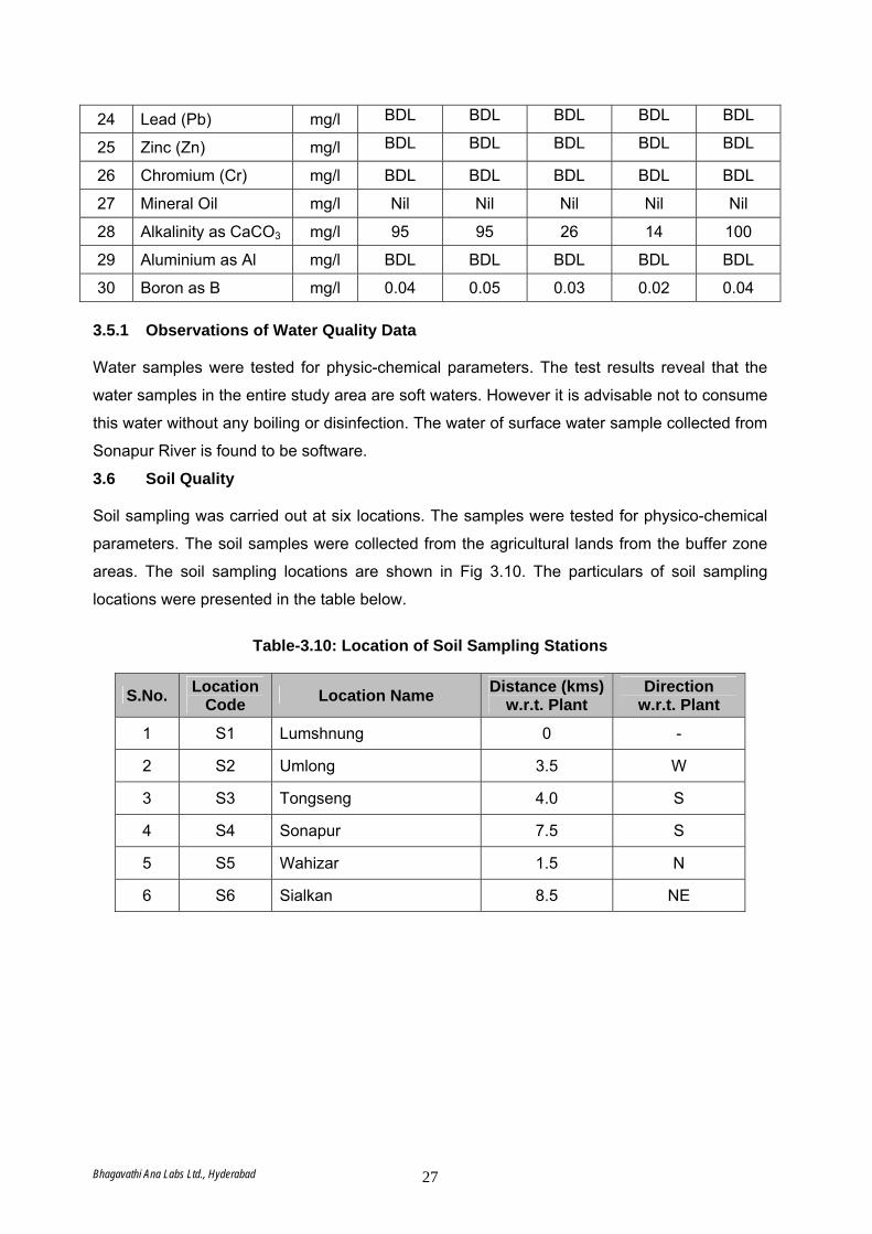
24 Lead (Pb) mg/l BDL BDL BDL BDL BDL
25 Zinc (Zn) mg/l BDL BDL BDL BDL BDL
26 Chromium (Cr) mg/l BDL BDL BDL BDL BDL
27 Mineral Oil mg/l Nil Nil Nil Nil Nil
28 Alkalinity as CaCO3 mg/l 95 95 26 14 100
29 Aluminium as Al mg/l BDL BDL BDL BDL BDL
30 Boron as B mg/l 0.04 0.05 0.03 0.02 0.04 3.5.1 Observations of Water Quality Data Water samples were tested for physic-chemical parameters. The test results reveal that the
water samples in the entire study area are soft waters. However it is advisable not to consume
this water without any boiling or disinfection. The water of surface water sample collected from
Sonapur River is found to be software.
3.6 Soil Quality Soil sampling was carried out at six locations. The samples were tested for physico-chemical
parameters. The soil samples were collected from the agricultural lands from the buffer zone
areas. The soil sampling locations are shown in Fig 3.10. The particulars of soil sampling
locations were presented in the table below.
Table-3.10: Location of Soil Sampling Stations
S.No. Location Code Location Name Distance (kms)
w.r.t. Plant Direction
w.r.t. Plant
1 S1 Lumshnung 0 -
2 S2 Umlong 3.5 W
3 S3 Tongseng 4.0 S
4 S4 Sonapur 7.5 S
5 S5 Wahizar 1.5 N
6 S6 Sialkan 8.5 NE
Bhagavathi Ana Labs Ltd., Hyderabad 27

Fig-3.10: Map showing Soil Sampling Locations
Bhagavathi Ana Labs Ltd., Hyderabad 28
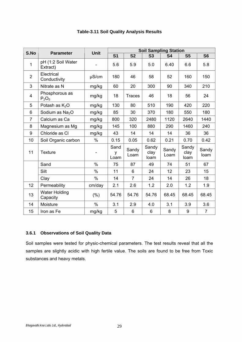
Table-3.11 Soil Quality Analysis Results
Soil Sampling Station S.No Parameter Unit S1 S2 S3 S4 S5 S6
1 pH (1:2 Soil Water Extract) - 5.6 5.9 5.0 6.40 6.6 5.8
2 Electrical Conductivity μS/cm 180 46 58 52 160 150
3 Nitrate as N mg/kg 60 20 300 90 340 210
4 Phosphorous as P2O5
mg/kg 18 Traces 46 18 56 24
5 Potash as K2O mg/kg 130 80 510 190 420 220 6 Sodium as Na2O mg/kg 85 30 370 180 550 180 7 Calcium as Ca mg/kg 800 320 2480 1120 2640 1440 8 Magnesium as Mg mg/kg 145 100 880 290 1460 240 9 Chloride as Cl mg/kg 43 14 14 14 36 36
10 Soil Organic carbon % 0.15 0.05 0.62 0.21 0.70 0.42
11 Texture - Sand
y Loam
Sandy Loam
Sandy clay loam
Sandy Loam
Sandy clay loam
Sandy loam
Sand % 75 87 49 74 51 67 Silt % 11 6 24 12 23 15 Clay % 14 7 24 14 26 18
12 Permeability cm/day 2.1 2.6 1.2 2.0 1.2 1.9
13 Water Holding Capacity (%) 54.76 54.76 54.76 68.45 68.45 68.45
14 Moisture % 3.1 2.9 4.0 3.1 3.9 3.6 15 Iron as Fe mg/kg 5 6 6 8 9 7
3.6.1 Observations of Soil Quality Data Soil samples were tested for physic-chemical parameters. The test results reveal that all the
samples are slightly acidic with high fertile value. The soils are found to be free from Toxic
substances and heavy metals.
Bhagavathi Ana Labs Ltd., Hyderabad 29
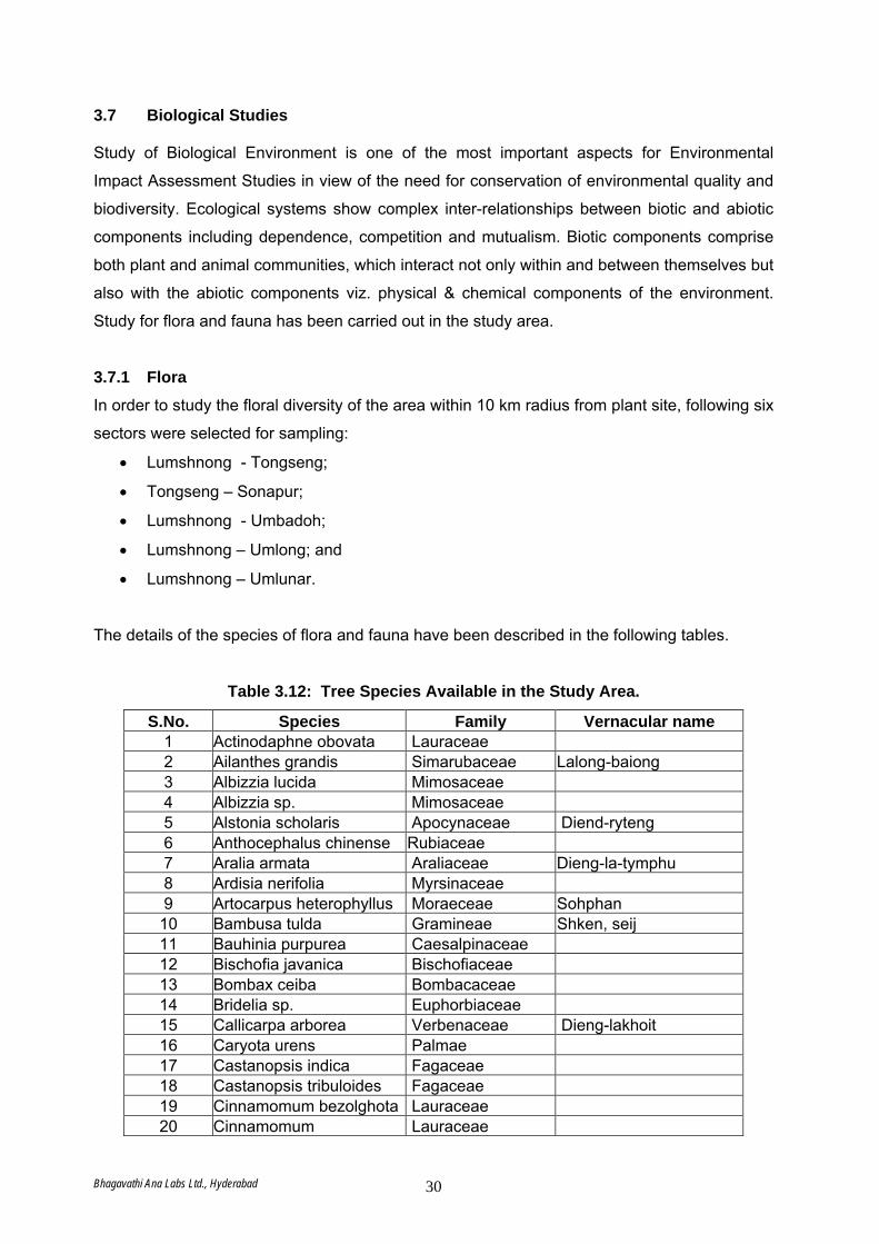
3.7 Biological Studies Study of Biological Environment is one of the most important aspects for Environmental
Impact Assessment Studies in view of the need for conservation of environmental quality and
biodiversity. Ecological systems show complex inter-relationships between biotic and abiotic
components including dependence, competition and mutualism. Biotic components comprise
both plant and animal communities, which interact not only within and between themselves but
also with the abiotic components viz. physical & chemical components of the environment.
Study for flora and fauna has been carried out in the study area.
3.7.1 Flora In order to study the floral diversity of the area within 10 km radius from plant site, following six
sectors were selected for sampling:
• Lumshnong - Tongseng;
• Tongseng – Sonapur;
• Lumshnong - Umbadoh;
• Lumshnong – Umlong; and
• Lumshnong – Umlunar.
The details of the species of flora and fauna have been described in the following tables.
Table 3.12: Tree Species Available in the Study Area.
S.No. Species Family Vernacular name 1 Actinodaphne obovata Lauraceae 2 Ailanthes grandis Simarubaceae Lalong-baiong 3 Albizzia lucida Mimosaceae 4 Albizzia sp. Mimosaceae 5 Alstonia scholaris Apocynaceae Diend-ryteng 6 Anthocephalus chinense Rubiaceae 7 Aralia armata Araliaceae Dieng-la-tymphu 8 Ardisia nerifolia Myrsinaceae 9 Artocarpus heterophyllus Moraeceae Sohphan
10 Bambusa tulda Gramineae Shken, seij 11 Bauhinia purpurea Caesalpinaceae 12 Bischofia javanica Bischofiaceae 13 Bombax ceiba Bombacaceae 14 Bridelia sp. Euphorbiaceae 15 Callicarpa arborea Verbenaceae Dieng-lakhoit 16 Caryota urens Palmae 17 Castanopsis indica Fagaceae 18 Castanopsis tribuloides Fagaceae 19 Cinnamomum bezolghota Lauraceae 20 Cinnamomum Lauraceae
Bhagavathi Ana Labs Ltd., Hyderabad 30
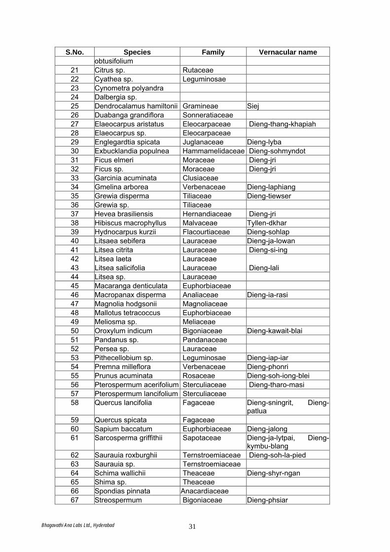
S.No. Species Family Vernacular name obtusifolium
21 Citrus sp. Rutaceae 22 Cyathea sp. Leguminosae 23 Cynometra polyandra 24 Dalbergia sp. 25 Dendrocalamus hamiltonii Gramineae Siej 26 Duabanga grandiflora Sonneratiaceae 27 Elaeocarpus aristatus Eleocarpaceae Dieng-thang-khapiah 28 Elaeocarpus sp. Eleocarpaceae 29 Englegardtia spicata Juglanaceae Dieng-lyba 30 Exbucklandia populnea Hammamelidaceae Dieng-sohmyndot 31 Ficus elmeri Moraceae Dieng-jri 32 Ficus sp. Moraceae Dieng-jri 33 Garcinia acuminata Clusiaceae 34 Gmelina arborea Verbenaceae Dieng-laphiang 35 Grewia disperma Tiliaceae Dieng-tiewser 36 Grewia sp. Tiliaceae 37 Hevea brasiliensis Hernandiaceae Dieng-jri 38 Hibiscus macrophyllus Malvaceae Tyllen-dkhar 39 Hydnocarpus kurzii Flacourtiaceae Dieng-sohlap 40 Litsaea sebifera Lauraceae Dieng-ja-lowan 41 Litsea citrita Lauraceae Dieng-si-ing 42 Litsea laeta Lauraceae 43 Litsea salicifolia Lauraceae Dieng-lali 44 Litsea sp. Lauraceae 45 Macaranga denticulata Euphorbiaceae 46 Macropanax disperma Analiaceae Dieng-ia-rasi 47 Magnolia hodgsonii Magnoliaceae 48 Mallotus tetracoccus Euphorbiaceae 49 Meliosma sp. Meliaceae 50 Oroxylum indicum Bigoniaceae Dieng-kawait-blai 51 Pandanus sp. Pandanaceae 52 Persea sp. Lauraceae 53 Pithecellobium sp. Leguminosae Dieng-iap-iar 54 Premna milleflora Verbenaceae Dieng-phonri 55 Prunus acuminata Rosaceae Dieng-soh-iong-blei 56 Pterospermum acerifolium Sterculiaceae Dieng-tharo-masi 57 Pterospermum lancifolium Sterculiaceae 58 Quercus lancifolia Fagaceae Dieng-sningrit, Dieng-
patlua 59 Quercus spicata Fagaceae 60 Sapium baccatum Euphorbiaceae Dieng-jalong 61 Sarcosperma griffithii Sapotaceae Dieng-ja-lytpai, Dieng-
kymbu-blang 62 Saurauia roxburghii Ternstroemiaceae Dieng-soh-la-pied 63 Saurauia sp. Ternstroemiaceae 64 Schima wallichii Theaceae Dieng-shyr-ngan 65 Shima sp. Theaceae 66 Spondias pinnata Anacardiaceae 67 Streospermum Bigoniaceae Dieng-phsiar
Bhagavathi Ana Labs Ltd., Hyderabad 31
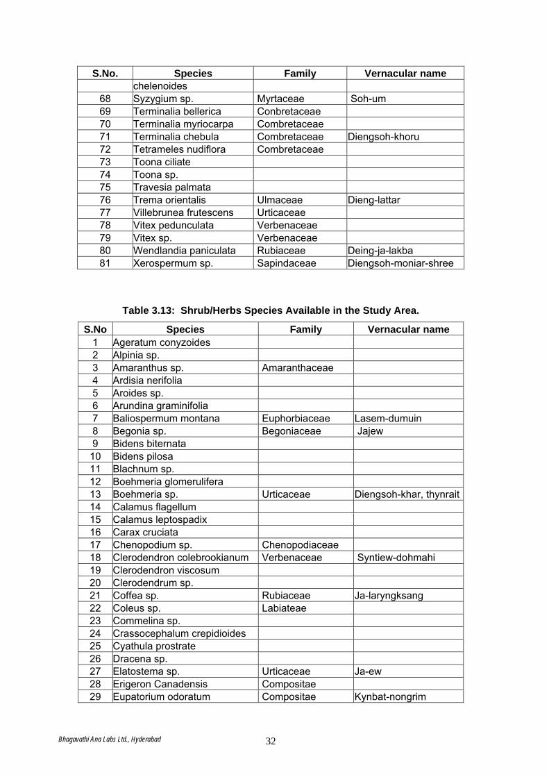
S.No. Species Family Vernacular name chelenoides
68 Syzygium sp. Myrtaceae Soh-um 69 Terminalia bellerica Conbretaceae 70 Terminalia myriocarpa Combretaceae 71 Terminalia chebula Combretaceae Diengsoh-khoru 72 Tetrameles nudiflora Combretaceae 73 Toona ciliate 74 Toona sp. 75 Travesia palmata 76 Trema orientalis Ulmaceae Dieng-lattar 77 Villebrunea frutescens Urticaceae 78 Vitex pedunculata Verbenaceae 79 Vitex sp. Verbenaceae 80 Wendlandia paniculata Rubiaceae Deing-ja-lakba 81 Xerospermum sp. Sapindaceae Diengsoh-moniar-shree
Table 3.13: Shrub/Herbs Species Available in the Study Area.
S.No Species Family Vernacular name 1 Ageratum conyzoides 2 Alpinia sp. 3 Amaranthus sp. Amaranthaceae 4 Ardisia nerifolia 5 Aroides sp. 6 Arundina graminifolia 7 Baliospermum montana Euphorbiaceae Lasem-dumuin 8 Begonia sp. Begoniaceae Jajew 9 Bidens biternata
10 Bidens pilosa 11 Blachnum sp. 12 Boehmeria glomerulifera 13 Boehmeria sp. Urticaceae Diengsoh-khar, thynrait 14 Calamus flagellum 15 Calamus leptospadix 16 Carax cruciata 17 Chenopodium sp. Chenopodiaceae 18 Clerodendron colebrookianum Verbenaceae Syntiew-dohmahi 19 Clerodendron viscosum 20 Clerodendrum sp. 21 Coffea sp. Rubiaceae Ja-laryngksang 22 Coleus sp. Labiateae 23 Commelina sp. 24 Crassocephalum crepidioides 25 Cyathula prostrate 26 Dracena sp. 27 Elatostema sp. Urticaceae Ja-ew 28 Erigeron Canadensis Compositae 29 Eupatorium odoratum Compositae Kynbat-nongrim
Bhagavathi Ana Labs Ltd., Hyderabad 32
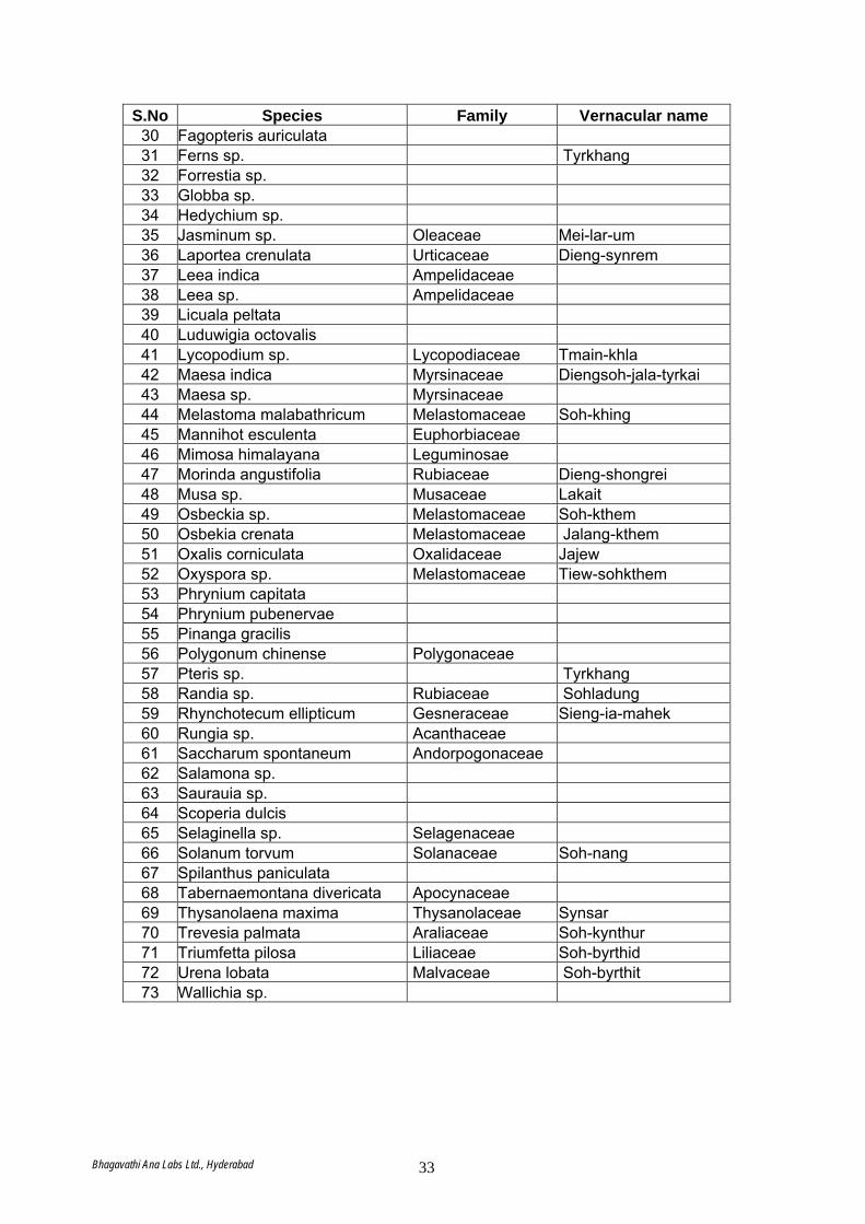
S.No Species Family Vernacular name 30 Fagopteris auriculata 31 Ferns sp. Tyrkhang 32 Forrestia sp. 33 Globba sp. 34 Hedychium sp. 35 Jasminum sp. Oleaceae Mei-lar-um 36 Laportea crenulata Urticaceae Dieng-synrem 37 Leea indica Ampelidaceae 38 Leea sp. Ampelidaceae 39 Licuala peltata 40 Luduwigia octovalis 41 Lycopodium sp. Lycopodiaceae Tmain-khla 42 Maesa indica Myrsinaceae Diengsoh-jala-tyrkai 43 Maesa sp. Myrsinaceae 44 Melastoma malabathricum Melastomaceae Soh-khing 45 Mannihot esculenta Euphorbiaceae 46 Mimosa himalayana Leguminosae 47 Morinda angustifolia Rubiaceae Dieng-shongrei 48 Musa sp. Musaceae Lakait 49 Osbeckia sp. Melastomaceae Soh-kthem 50 Osbekia crenata Melastomaceae Jalang-kthem 51 Oxalis corniculata Oxalidaceae Jajew 52 Oxyspora sp. Melastomaceae Tiew-sohkthem 53 Phrynium capitata 54 Phrynium pubenervae 55 Pinanga gracilis 56 Polygonum chinense Polygonaceae 57 Pteris sp. Tyrkhang 58 Randia sp. Rubiaceae Sohladung 59 Rhynchotecum ellipticum Gesneraceae Sieng-ia-mahek 60 Rungia sp. Acanthaceae 61 Saccharum spontaneum Andorpogonaceae 62 Salamona sp. 63 Saurauia sp. 64 Scoperia dulcis 65 Selaginella sp. Selagenaceae 66 Solanum torvum Solanaceae Soh-nang 67 Spilanthus paniculata 68 Tabernaemontana divericata Apocynaceae 69 Thysanolaena maxima Thysanolaceae Synsar 70 Trevesia palmata Araliaceae Soh-kynthur 71 Triumfetta pilosa Liliaceae Soh-byrthid 72 Urena lobata Malvaceae Soh-byrthit 73 Wallichia sp.
Bhagavathi Ana Labs Ltd., Hyderabad 33
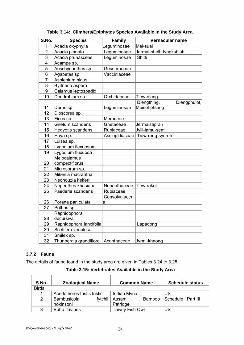
Table 3.14: Climbers/Epiphytes Species Available in the Study Area.
S.No. Species Family Vernacular name 1 Acacia oxyphylla Leguminosae Mei-suai 2 Acacia pinnata Leguminosae Jermai-sheih-lyngkshiah 3 Acacia prunascens Leguminosae Shitli 4 Acampe sp. 5 Aeschynanthus sp. Gesneraceae 6 Agapetes sp. Vacciniaceae 7 Asplenium nidus 8 Byttneria aspera 9 Calamus leptospadix
10 Dendrobium sp. Orchidaceae Tiew-dieng
11 Derris sp. Leguminosae Diengthing, Diengphulot, Meisohphlang
12 Dioscorea sp. 13 Ficus sp. Moraceae 14 Gnetum scandens Gnetaceae Jermaisaprah 15 Hedyotis scandens Rubiaceae Jylli-iamu-sem 16 Hoya sp. Asclepidiaceae Tiew-reng-synreh 17 Luisea sp. 18 Lygodium flexuosum 19 Lygodium fluxuosa
20 Melocalamus compectiflorus
21 Microsorum sp. 22 Mikenia macrantha 23 Neohouzia helferii 24 Nepenthes khasiana Nepenthaceae Tiew-rakot 25 Paederia scandens Rubiaceae
26 Porana paniculata Convolvulaceae
27 Pothos sp.
28 Raphidophora decursiva
29 Raphidophora lancifolia Lapadong 30 Scefflera venulosa 31 Smilex sp. 32 Thunbergia grandiflora Acanthaceae Jyrmi-khnong
3.7.2 Fauna The details of fauna found in the study area are given in Tables 3.24 to 3.25.
Table 3.15: Vertebrates Available in the Study Area
S.No.
Zoological Name
Common Name
Schedule status
Birds 1 Acridotheres tristis tristis Indian Myna US 2 Bambusicola fytchii
hokinsoni Assam Bamboo Patridge
Schedule I Part III
3 Bubo flavipes Tawny Fish Owl US
Bhagavathi Ana Labs Ltd., Hyderabad 34
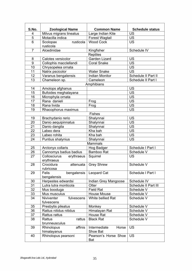
S.No.
Zoological Name
Common Name
Schedule status
4 Milvus migrans lineatus Large Indian Kite US 5 Motacilla indica Forest Wagtail US 6 Scolopax rusticola
rusticola Wood Cock US
7 Alcedinidae Kingfisher Schedule IV Reptiles
8 Calotes versicolor Garden Lizard US 9 Collophis macclellandi Coral Snake US
10 Chrysopelea ornata US 11 Natrix pscicolor Water Snake US 12 Varanus bengalensis Indian Monitor Schedule II Part II 13 Chameleon sp. Cameleon Schedule II Part I
Amphibians 14 Amolops afghanus US 15 Bufoides meghalayana US 16 Microphyla ornata US 17 Rana danieli Frog US 18 Rana livida Frog US 19 Rhacophorus maximus US
Fishes 19 Brachydanio rerio Shalynnai US 20 Danio aequipinnatus Shalynnai US 21 Danio dangila Shalynnai US 22 Labeo dera Kha bah US 23 Labeo rohita Kha bah US 24 Puntius shalynius Shalynnai US
Mammals 25 Arctonyx collaris Hog Badger Schedule I Part I 26 Cannomys badius badius Bamboo Rat Schedule V 27 Collosciurus erythraeus
erythraeus Squirrel US
28 Crocidura attenuata rubricosa
Grey Shrew Schedule V
29 Felis bengalensis bengalensis
Leopard Cat Schedule I Part I
30 Herpestes edwardsi Indian Grey Mangoose Schedule IV 31 Lutra lutra monticola Otter Schedule II Part III 32 Mus booduga Field Rat Schedule V 33 Mus musculus House Mouse Schedule V 34 Niviventer fulvescens
fulvescens White bellied Rat Schedule V
35 Presbytis pileatus Monkey Schedule V 36 Rattus nitidus nitidus Himalayan Rat Schedule V 37 Rattus rattus House Rat Schedule V 38 Rattus rattus
brunneusculus Black Rat Schedule V
39 Rhinolopus affinis himalayanus
Intermediate Horse Shoe Bat
US
40 Rhinolopus pearsoni Pearson’s Horse Shoe Bat
US
Bhagavathi Ana Labs Ltd., Hyderabad 35
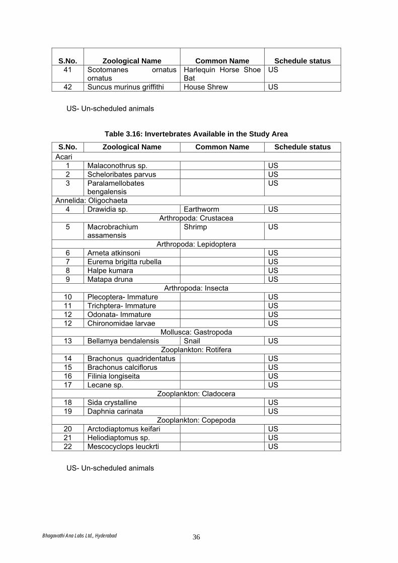
S.No.
Zoological Name
Common Name
Schedule status
41 Scotomanes ornatus ornatus
Harlequin Horse Shoe Bat
US
42 Suncus murinus griffithi House Shrew US
US- Un-scheduled animals
Table 3.16: Invertebrates Available in the Study Area
S.No. Zoological Name Common Name Schedule status Acari
1 Malaconothrus sp. US 2 Scheloribates parvus US 3 Paralamellobates
bengalensis US
Annelida: Oligochaeta 4 Drawidia sp. Earthworm US
Arthropoda: Crustacea 5 Macrobrachium
assamensis Shrimp US
Arthropoda: Lepidoptera 6 Arneta atkinsoni US 7 Eurema brigitta rubella US 8 Halpe kumara US 9 Matapa druna US
Arthropoda: Insecta 10 Plecoptera- Immature US 11 Trichptera- Immature US 12 Odonata- Immature US 12 Chironomidae larvae US
Mollusca: Gastropoda 13 Bellamya bendalensis Snail US
Zooplankton: Rotifera 14 Brachonus quadridentatus US 15 Brachonus calciflorus US 16 Filinia longiseita US 17 Lecane sp. US
Zooplankton: Cladocera 18 Sida crystalline US 19 Daphnia carinata US
Zooplankton: Copepoda 20 Arctodiaptomus keifari US 21 Heliodiaptomus sp. US 22 Mescocyclops leuckrti US
US- Un-scheduled animals
Bhagavathi Ana Labs Ltd., Hyderabad 36
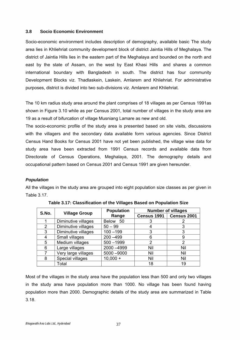
3.8 Socio Economic Environment Socio-economic environment includes description of demography, available basic The study
area lies in Khliehriat community development block of district Jaintia Hills of Meghalaya. The
district of Jaintia Hills lies in the eastern part of the Meghalaya and bounded on the north and
east by the state of Assam, on the west by East Khasi Hills and shares a common
international boundary with Bangladesh in south. The district has four community
Development Blocks viz. Thadlaskein, Laskein, Amlarem and Khliehriat. For administrative
purposes, district is divided into two sub-divisions viz. Amlarem and Khliehriat.
The 10 km radius study area around the plant comprises of 18 villages as per Census 1991as
shown in Figure 3.10 while as per Census 2001, total number of villages in the study area are
19 as a result of bifurcation of village Musniang Lamare as new and old.
The socio-economic profile of the study area is presented based on site visits, discussions
with the villagers and the secondary data available form various agencies. Since District
Census Hand Books for Census 2001 have not yet been published, the village wise data for
study area have been extracted from 1991 Census records and available data from
Directorate of Census Operations, Meghalaya, 2001. The demography details and
occupational pattern based on Census 2001 and Census 1991 are given hereunder.
Population
All the villages in the study area are grouped into eight population size classes as per given in
Table 3.17.
Table 3.17: Classification of the Villages Based on Population Size
Number of villages S.No. Village Group Population Range Census 1991 Census 2001
1 Diminutive villages Below 50 3 2 2 Diminutive villages 50 – 99 4 3 3 Diminutive villages 100 –199 3 3 4 Small villages 200 –499 6 9 5 Medium villages 500 –1999 2 2 6 Large villages 2000 –4999 Nil Nil 7 Very large villages 5000 –9000 Nil Nil 8 Special villages 10,000 + Nil Nil Total 18 19
Most of the villages in the study area have the population less than 500 and only two villages
in the study area have population more than 1000. No village has been found having
population more than 2000. Demographic details of the study area are summarized in Table
3.18.
Bhagavathi Ana Labs Ltd., Hyderabad 37
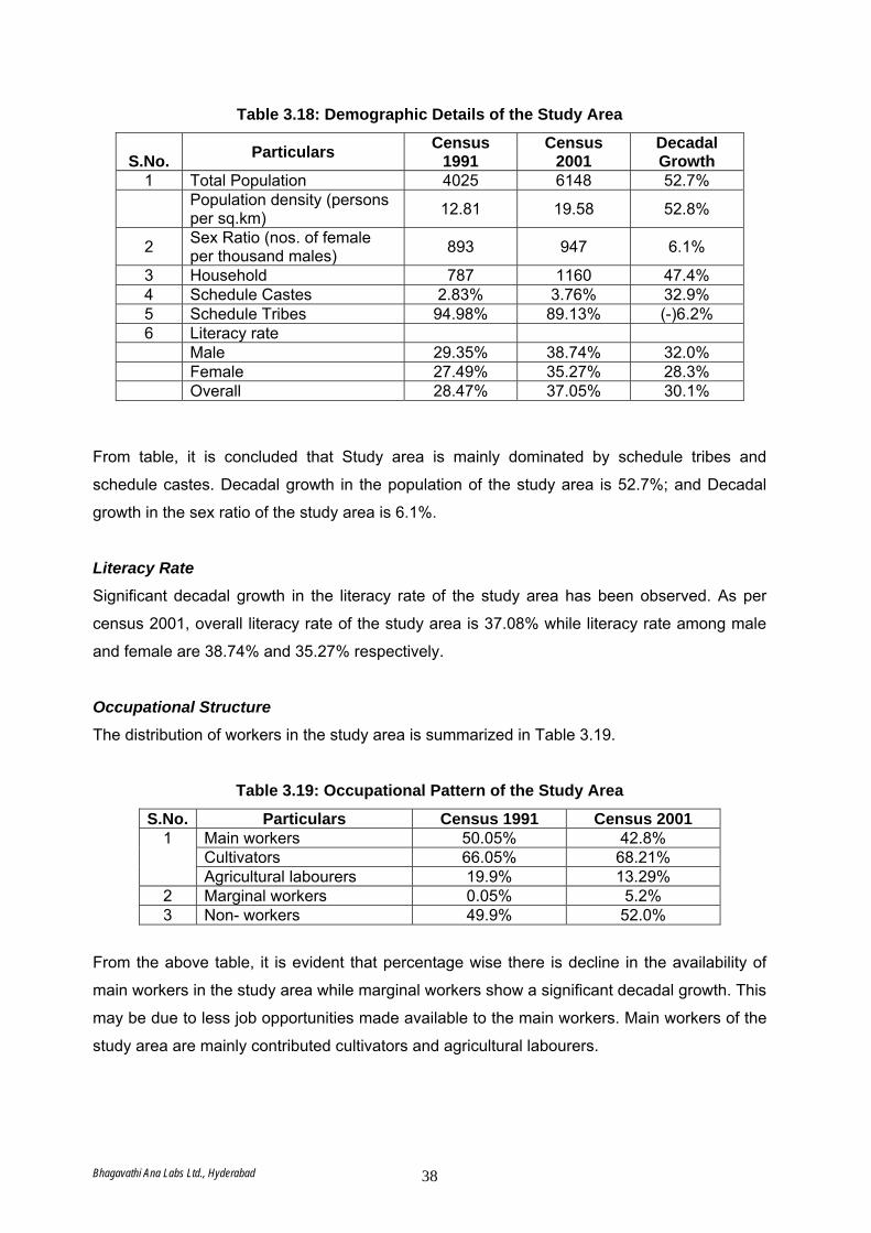
Table 3.18: Demographic Details of the Study Area
S.No. Particulars Census
1991 Census
2001 Decadal Growth
1 Total Population 4025 6148 52.7%
Population density (persons per sq.km) 12.81 19.58 52.8%
2 Sex Ratio (nos. of female per thousand males) 893 947 6.1%
3 Household 787 1160 47.4% 4 Schedule Castes 2.83% 3.76% 32.9% 5 Schedule Tribes 94.98% 89.13% (-)6.2% 6 Literacy rate Male 29.35% 38.74% 32.0% Female 27.49% 35.27% 28.3% Overall 28.47% 37.05% 30.1%
From table, it is concluded that Study area is mainly dominated by schedule tribes and
schedule castes. Decadal growth in the population of the study area is 52.7%; and Decadal
growth in the sex ratio of the study area is 6.1%.
Literacy Rate
Significant decadal growth in the literacy rate of the study area has been observed. As per
census 2001, overall literacy rate of the study area is 37.08% while literacy rate among male
and female are 38.74% and 35.27% respectively.
Occupational Structure
The distribution of workers in the study area is summarized in Table 3.19.
Table 3.19: Occupational Pattern of the Study Area
S.No. Particulars Census 1991 Census 2001 Main workers 50.05% 42.8% Cultivators 66.05% 68.21%
1
Agricultural labourers 19.9% 13.29% 2 Marginal workers 0.05% 5.2% 3 Non- workers 49.9% 52.0%
From the above table, it is evident that percentage wise there is decline in the availability of
main workers in the study area while marginal workers show a significant decadal growth. This
may be due to less job opportunities made available to the main workers. Main workers of the
study area are mainly contributed cultivators and agricultural labourers.
Bhagavathi Ana Labs Ltd., Hyderabad 38
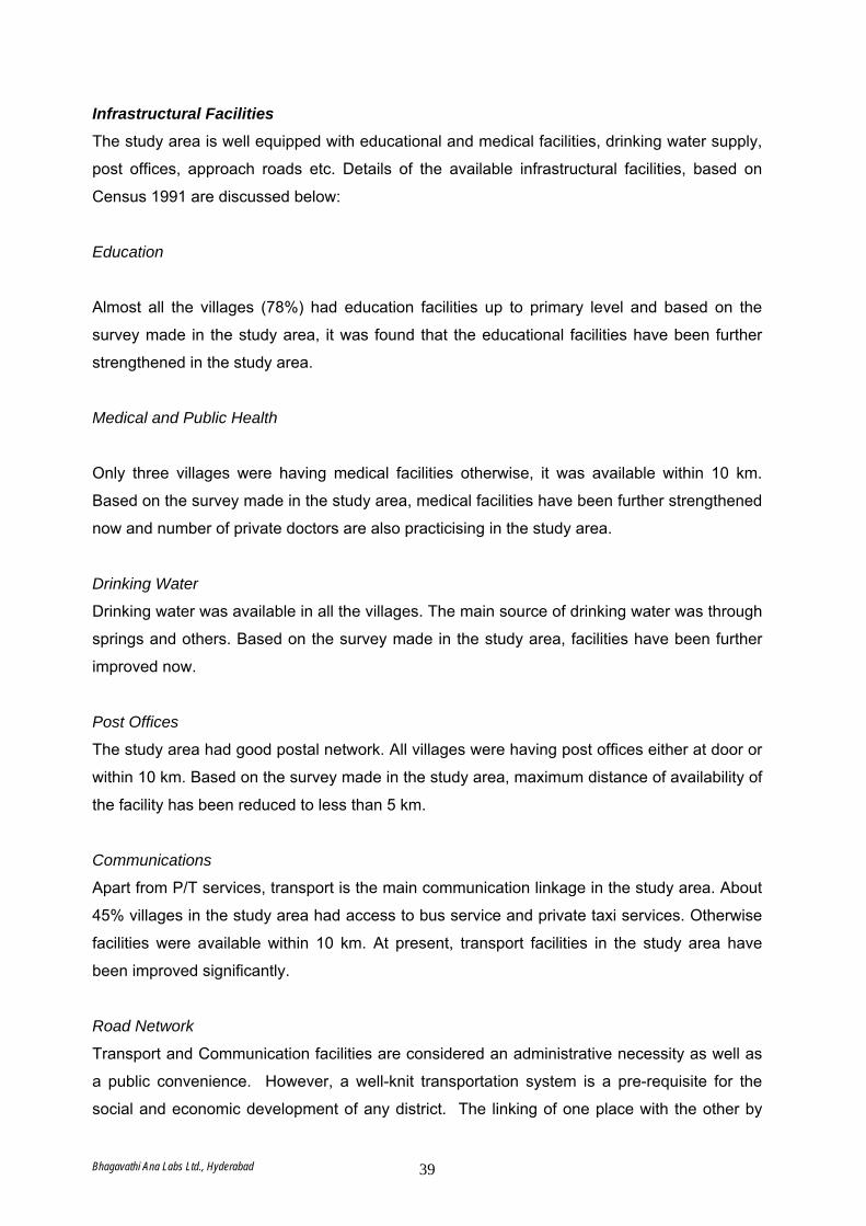
Infrastructural Facilities
The study area is well equipped with educational and medical facilities, drinking water supply,
post offices, approach roads etc. Details of the available infrastructural facilities, based on
Census 1991 are discussed below:
Education
Almost all the villages (78%) had education facilities up to primary level and based on the
survey made in the study area, it was found that the educational facilities have been further
strengthened in the study area.
Medical and Public Health
Only three villages were having medical facilities otherwise, it was available within 10 km.
Based on the survey made in the study area, medical facilities have been further strengthened
now and number of private doctors are also practicising in the study area.
Drinking Water
Drinking water was available in all the villages. The main source of drinking water was through
springs and others. Based on the survey made in the study area, facilities have been further
improved now.
Post Offices
The study area had good postal network. All villages were having post offices either at door or
within 10 km. Based on the survey made in the study area, maximum distance of availability of
the facility has been reduced to less than 5 km.
Communications
Apart from P/T services, transport is the main communication linkage in the study area. About
45% villages in the study area had access to bus service and private taxi services. Otherwise
facilities were available within 10 km. At present, transport facilities in the study area have
been improved significantly.
Road Network
Transport and Communication facilities are considered an administrative necessity as well as
a public convenience. However, a well-knit transportation system is a pre-requisite for the
social and economic development of any district. The linking of one place with the other by
Bhagavathi Ana Labs Ltd., Hyderabad 39
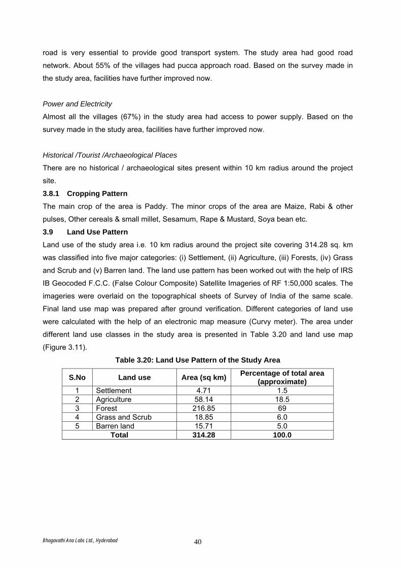
road is very essential to provide good transport system. The study area had good road
network. About 55% of the villages had pucca approach road. Based on the survey made in
the study area, facilities have further improved now.
Power and Electricity
Almost all the villages (67%) in the study area had access to power supply. Based on the
survey made in the study area, facilities have further improved now.
Historical /Tourist /Archaeological Places
There are no historical / archaeological sites present within 10 km radius around the project
site.
3.8.1 Cropping Pattern The main crop of the area is Paddy. The minor crops of the area are Maize, Rabi & other
pulses, Other cereals & small millet, Sesamum, Rape & Mustard, Soya bean etc.
3.9 Land Use Pattern Land use of the study area i.e. 10 km radius around the project site covering 314.28 sq. km
was classified into five major categories: (i) Settlement, (ii) Agriculture, (iii) Forests, (iv) Grass
and Scrub and (v) Barren land. The land use pattern has been worked out with the help of IRS
IB Geocoded F.C.C. (False Colour Composite) Satellite Imageries of RF 1:50,000 scales. The
imageries were overlaid on the topographical sheets of Survey of India of the same scale.
Final land use map was prepared after ground verification. Different categories of land use
were calculated with the help of an electronic map measure (Curvy meter). The area under
different land use classes in the study area is presented in Table 3.20 and land use map
(Figure 3.11).
Table 3.20: Land Use Pattern of the Study Area
S.No Land use Area (sq km) Percentage of total area (approximate)
1 Settlement 4.71 1.5 2 Agriculture 58.14 18.5 3 Forest 216.85 69 4 Grass and Scrub 18.85 6.0 5 Barren land 15.71 5.0
Total 314.28 100.0
Bhagavathi Ana Labs Ltd., Hyderabad 40

Figure 3.11 Land Use Pattern of the Study Area
The forest cover is 216.85 sq. km, which accounts for 69% of the geographical area.
Agriculture is the next important land use in the area. Most of the agricultural lands account for
orchard, paddy fields etc. The tone and texture of imageries clearly identified the grass and
scrubs, which account for about 6% of the total geographical area. Barren land which occupies
about 5% of the area includes broken land, rocky knobs, boulders and sandy river bed.
Bhagavathi Ana Labs Ltd., Hyderabad 41

Bhagavathi Ana Labs Ltd., Hyderabad 42
ENVIRONMENTAL IMPACT ASSESSMENT
Star Cement Meghalaya Limited, Meghalaya
Bhagavathi Ana Labs Ltd., Hyderabad 65
4.0 IMPACT ASSESSMENT This chapter presents identification and appraisal of various impacts from the proposed
clinkerization and captive power plants in the study area.
4.1 Prediction of Impacts Prediction of Impacts is the most important component in the Environmental Impact
Assessment studies. Several scientific techniques and methodologies are available to predict
impacts of developmental activities on physical, ecological and socio-economic
environments. Such predictions are superimposed over the baseline (pre-project) status of
environmental quality to derive the ultimate (Post-project) scenario of environmental
conditions.
The prediction of impacts helps in minimizing the adverse impacts on environmental quality
during pre and post project execution. In case of water, land and socio-economic
environments, the predictions have been made based on available scientific knowledge and
judgments.
In this chapter, an attempt has been made to predict the incremental rise of various ground
level concentrations above the baseline status due to the emissions from this proposed
expansion project.
4.2 Assessment / Evaluation of Impacts The identification and general assessment of impacts of the proposed project has been
carried out in the earlier section. The impact of activities related to proposed project on each
environmental attribute was assessed. The environmental impact evaluation presented in this
section describes the cumulative impact of all project activities on each environmental
attribute in the local environmental setting. The impact on various environmental attributes is
expressed in appropriate units so as to arrive at an aggregate score of the “Environmental
Impact” of the project. This exercise results in a whole number, which could be used in
decision making without any ambiguity.
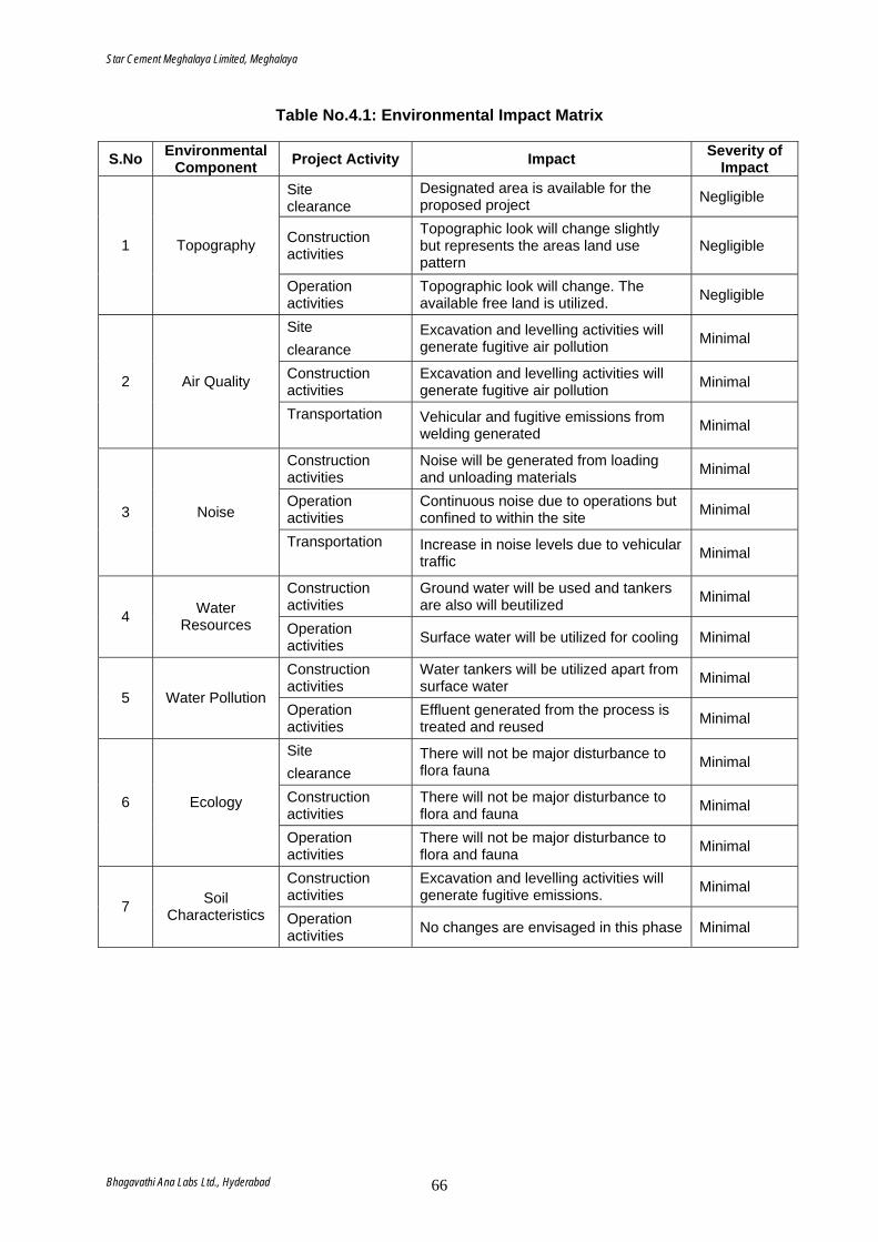
Star Cement Meghalaya Limited, Meghalaya
Bhagavathi Ana Labs Ltd., Hyderabad 66
Table No.4.1: Environmental Impact Matrix
S.No Environmental Component Project Activity Impact Severity of
Impact Site clearance
Designated area is available for the proposed project Negligible
Construction activities
Topographic look will change slightly but represents the areas land use pattern
Negligible 1 Topography
Operation activities
Topographic look will change. The available free land is utilized. Negligible
Site clearance
Excavation and levelling activities will generate fugitive air pollution Minimal
Construction activities
Excavation and levelling activities will generate fugitive air pollution Minimal 2 Air Quality
Transportation
Vehicular and fugitive emissions from welding generated Minimal
Construction activities
Noise will be generated from loading and unloading materials Minimal
Operation activities
Continuous noise due to operations but confined to within the site Minimal 3 Noise
Transportation
Increase in noise levels due to vehicular traffic Minimal
Construction activities
Ground water will be used and tankers are also will beutilized Minimal
4 Water Resources Operation
activities Surface water will be utilized for cooling Minimal
Construction activities
Water tankers will be utilized apart from surface water Minimal
5 Water Pollution Operation activities
Effluent generated from the process is treated and reused Minimal
Site clearance
There will not be major disturbance to flora fauna Minimal
Construction activities
There will not be major disturbance to flora and fauna Minimal 6 Ecology
Operation activities
There will not be major disturbance to flora and fauna Minimal
Construction activities
Excavation and levelling activities will generate fugitive emissions. Minimal
7 Soil Characteristics Operation
activities No changes are envisaged in this phase Minimal
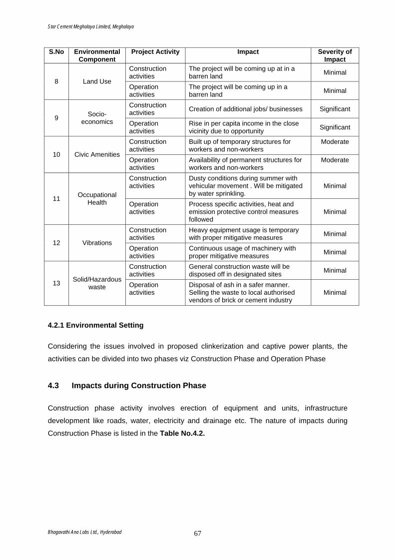
Star Cement Meghalaya Limited, Meghalaya
Bhagavathi Ana Labs Ltd., Hyderabad 67
S.No Environmental Component
Project Activity Impact Severity of Impact
Construction activities
The project will be coming up at in a barren land Minimal
8 Land Use Operation activities
The project will be coming up in a barren land Minimal
Construction activities Creation of additional jobs/ businesses Significant
9 Socio-economics Operation
activities Rise in per capita income in the close vicinity due to opportunity Significant
Construction activities
Built up of temporary structures for workers and non-workers
Moderate
10 Civic Amenities Operation activities
Availability of permanent structures for workers and non-workers
Moderate
Construction activities
Dusty conditions during summer with vehicular movement . Will be mitigated by water sprinkling.
Minimal
11 Occupational Health Operation
activities Process specific activities, heat and emission protective control measures followed
Minimal
Construction activities
Heavy equipment usage is temporary with proper mitigative measures Minimal
12 Vibrations Operation activities
Continuous usage of machinery with proper mitigative measures Minimal
Construction activities
General construction waste will be disposed off in designated sites Minimal
13 Solid/Hazardous waste Operation
activities Disposal of ash in a safer manner. Selling the waste to local authorised vendors of brick or cement industry
Minimal
4.2.1 Environmental Setting
Considering the issues involved in proposed clinkerization and captive power plants, the
activities can be divided into two phases viz Construction Phase and Operation Phase
4.3 Impacts during Construction Phase Construction phase activity involves erection of equipment and units, infrastructure
development like roads, water, electricity and drainage etc. The nature of impacts during
Construction Phase is listed in the Table No.4.2.
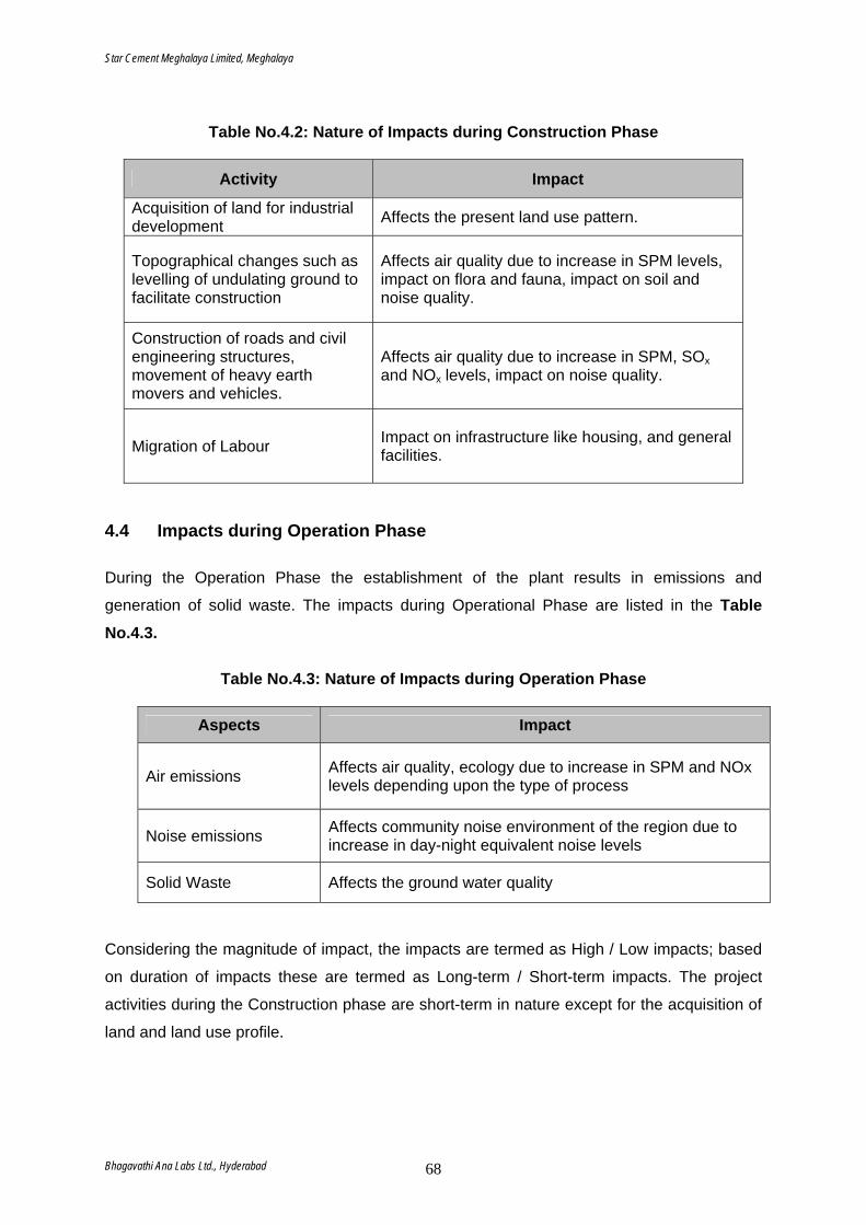
Star Cement Meghalaya Limited, Meghalaya
Bhagavathi Ana Labs Ltd., Hyderabad 68
Table No.4.2: Nature of Impacts during Construction Phase
Activity Impact
Acquisition of land for industrial development Affects the present land use pattern.
Topographical changes such as levelling of undulating ground to facilitate construction
Affects air quality due to increase in SPM levels, impact on flora and fauna, impact on soil and noise quality.
Construction of roads and civil engineering structures, movement of heavy earth movers and vehicles.
Affects air quality due to increase in SPM, SOx and NOx levels, impact on noise quality.
Migration of Labour Impact on infrastructure like housing, and general facilities.
4.4 Impacts during Operation Phase
During the Operation Phase the establishment of the plant results in emissions and
generation of solid waste. The impacts during Operational Phase are listed in the Table No.4.3.
Table No.4.3: Nature of Impacts during Operation Phase
Aspects Impact
Air emissions Affects air quality, ecology due to increase in SPM and NOx levels depending upon the type of process
Noise emissions Affects community noise environment of the region due to increase in day-night equivalent noise levels
Solid Waste Affects the ground water quality
Considering the magnitude of impact, the impacts are termed as High / Low impacts; based
on duration of impacts these are termed as Long-term / Short-term impacts. The project
activities during the Construction phase are short-term in nature except for the acquisition of
land and land use profile.
Star Cement Meghalaya Limited, Meghalaya
Bhagavathi Ana Labs Ltd., Hyderabad 69
4.4.1 Air Pollution
Major sources of air pollution are emission from mills, bag houses, kiln, crushers and stock
piles. Fugitive Dust Emissions are also inevitable from Raw Material Handling System and
the packaging and transportation sections. The types of pollutants discharged and their
concentrations are presented in the subsequent sections in this chapter.
Emissions released from the plant during operation phase will get dispersed in the
atmosphere and finally reach the ground at a specified distance from the sources. In the
proposed cement plant the possible environmental impacts on air quality has been
envisaged due to the following sources.
Cement Plant Point Source Emissions
Emissions from various chimneys have been considered as point sources, from the
proposed plant. Each point source is identified based on the location of the each stack and
emission strength and flue gas properties. Suitable pollution control systems will be installed
to clean the flue gas at each point source emissions.
The list of point sources and their characteristics are discussed in the Table. For the purpose
of air pollution modelling, controlled emissions at the out let of each pollution control system
have been considered.
However in the proposed cement plant, a closed clinker stock pile has been proposed and
suitable ventilation system with bag filter is proposed and hence the emissions from the
stock piles have been considered as point sources with controlled emissions.
Captive Thermal Power Plant Point Source Emissions
Emissions from the chimney have been considered as point source. The source is identified
based on the location of the stack and emission strength and flue gas properties. Suitable
pollution control systems will be installed to clean the flue gas.
Star Cement Meghalaya Limited, Meghalaya
Bhagavathi Ana Labs Ltd., Hyderabad 70
Transportation of Raw Material & Finished Goods
The emissions from transportation of Raw Material and Finished Goods within the study area
have been considered as line source emissions all along the road. For calculation of
emission factors, the roads have been considered as asphalted/Cement concrete. Emissions from Various Sources Particulate Matter Cement Plant
Major pollutant emitted from the cement plant is Particulate matter. Various major sources of
particulate emission from the proposed cement plant constitute flue gases from Kiln/Raw
mill, Coal mill, cement mill and cooler. Other sources of particulate system include
Limestone crusher, Raw material storage cum blending silo, Raw Coal handling & crushing,
Clinker stock pile, Clinker transport to cement mill, Clinker Hopper at cement mill section,
Cement Silo and Packing Machines. All the pollution control equipment in the proposed
cement plant are designed for an outlet emission of less than 50 mg/Nm3.
It is proposed to install a bag house for raw mill/Kiln, bag filter for coal mill and cement mill
and ESP for cooler. At all other sources, SCML proposes to install suitable bag filter
systems. All the pollution control systems will be designed for on outlet concentration less
than 50 mg/Nm3. The dust collected from the various pollution control equipment will be
recycled in the cement manufacturing process. The other pollutants generated from the
cement plant are SO2 and NOX. SO2 emissions have been computed based on the sulphur
content in the coal and quantity of coal fired in the kiln.
Captive Power Plant Particulate matter in power plant is due to the ash content of coal. The ash is collected at the
bottom in wet form as bottom ash. This will be grinded and used for cement manufacturing.
An ESP with outlet concentration of 50 mg/Nm3 will be provided.
Captive Limestone Mines Fugitive dust emissions from material handling and transportation on unpaved haulage roads
will result in particulate matter emissions.
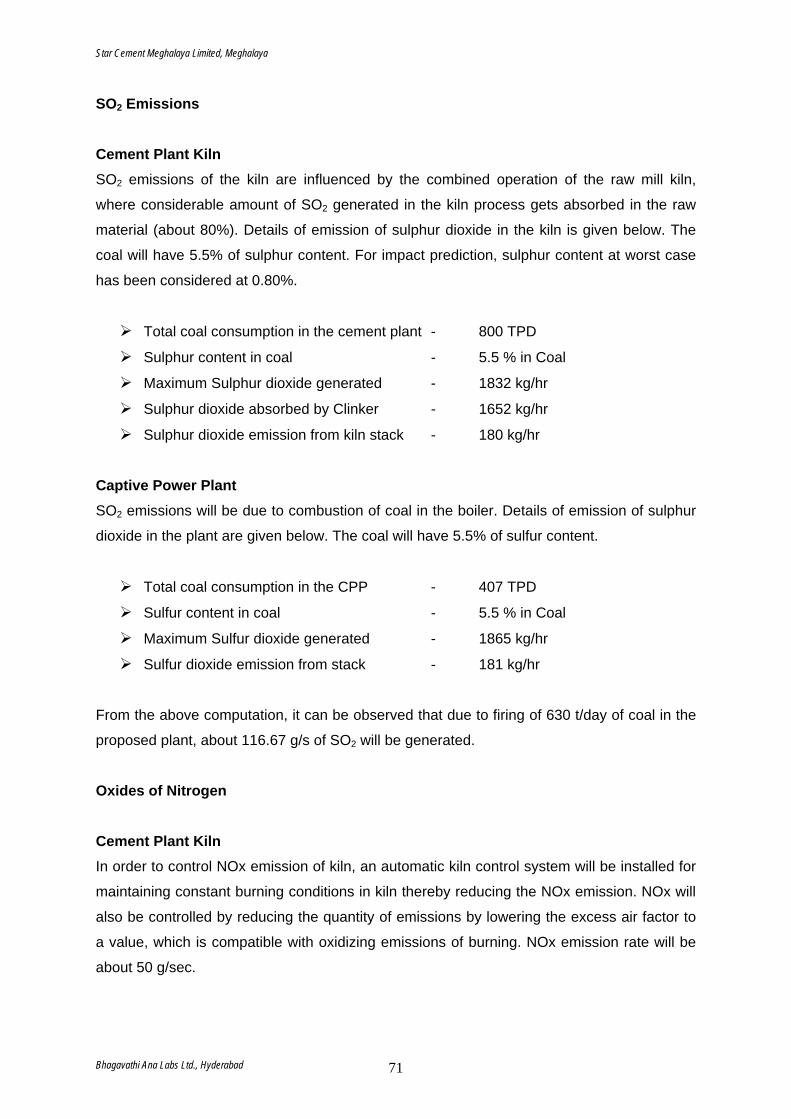
Star Cement Meghalaya Limited, Meghalaya
Bhagavathi Ana Labs Ltd., Hyderabad 71
SO2 Emissions Cement Plant Kiln SO2 emissions of the kiln are influenced by the combined operation of the raw mill kiln,
where considerable amount of SO2 generated in the kiln process gets absorbed in the raw
material (about 80%). Details of emission of sulphur dioxide in the kiln is given below. The
coal will have 5.5% of sulphur content. For impact prediction, sulphur content at worst case
has been considered at 0.80%.
Total coal consumption in the cement plant - 800 TPD
Sulphur content in coal - 5.5 % in Coal
Maximum Sulphur dioxide generated - 1832 kg/hr
Sulphur dioxide absorbed by Clinker - 1652 kg/hr
Sulphur dioxide emission from kiln stack - 180 kg/hr
Captive Power Plant SO2 emissions will be due to combustion of coal in the boiler. Details of emission of sulphur
dioxide in the plant are given below. The coal will have 5.5% of sulfur content.
Total coal consumption in the CPP - 407 TPD
Sulfur content in coal - 5.5 % in Coal
Maximum Sulfur dioxide generated - 1865 kg/hr
Sulfur dioxide emission from stack - 181 kg/hr
From the above computation, it can be observed that due to firing of 630 t/day of coal in the
proposed plant, about 116.67 g/s of SO2 will be generated.
Oxides of Nitrogen Cement Plant Kiln In order to control NOx emission of kiln, an automatic kiln control system will be installed for
maintaining constant burning conditions in kiln thereby reducing the NOx emission. NOx will
also be controlled by reducing the quantity of emissions by lowering the excess air factor to
a value, which is compatible with oxidizing emissions of burning. NOx emission rate will be
about 50 g/sec.
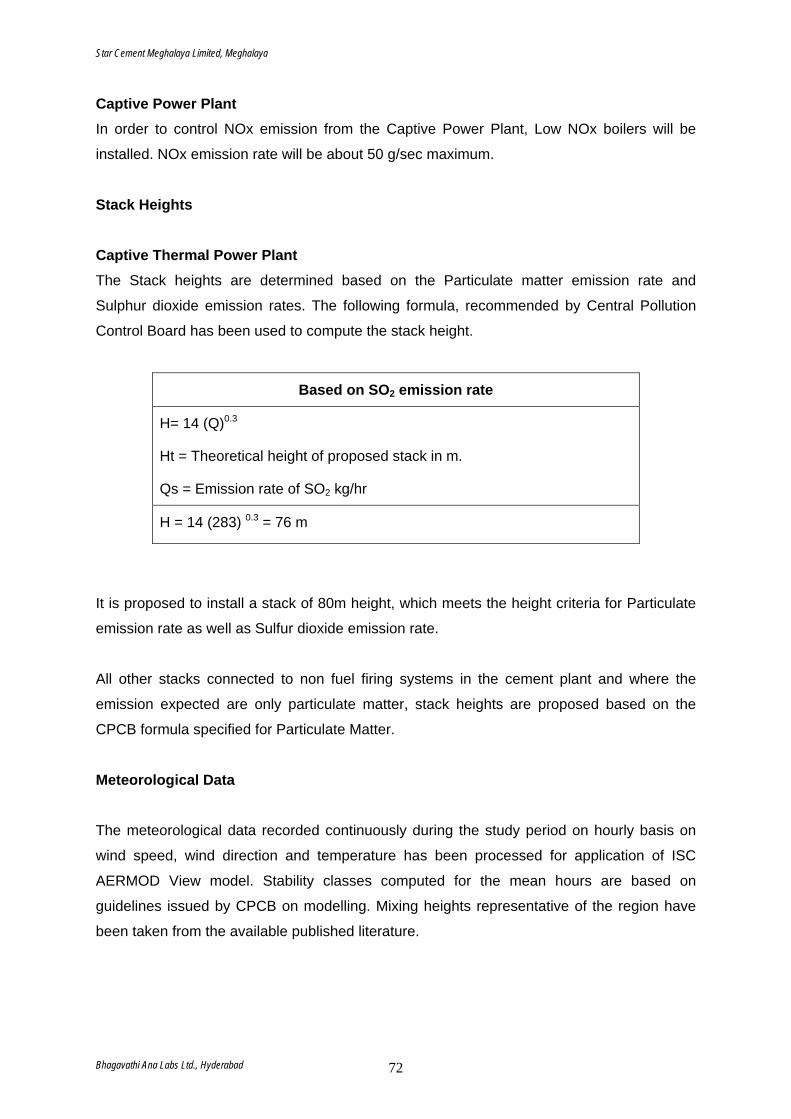
Star Cement Meghalaya Limited, Meghalaya
Bhagavathi Ana Labs Ltd., Hyderabad 72
Captive Power Plant In order to control NOx emission from the Captive Power Plant, Low NOx boilers will be
installed. NOx emission rate will be about 50 g/sec maximum.
Stack Heights
Captive Thermal Power Plant The Stack heights are determined based on the Particulate matter emission rate and
Sulphur dioxide emission rates. The following formula, recommended by Central Pollution
Control Board has been used to compute the stack height.
Based on SO2 emission rate
H= 14 (Q)0.3
Ht = Theoretical height of proposed stack in m.
Qs = Emission rate of SO2 kg/hr
H = 14 (283) 0.3 = 76 m
It is proposed to install a stack of 80m height, which meets the height criteria for Particulate
emission rate as well as Sulfur dioxide emission rate.
All other stacks connected to non fuel firing systems in the cement plant and where the
emission expected are only particulate matter, stack heights are proposed based on the
CPCB formula specified for Particulate Matter.
Meteorological Data The meteorological data recorded continuously during the study period on hourly basis on
wind speed, wind direction and temperature has been processed for application of ISC
AERMOD View model. Stability classes computed for the mean hours are based on
guidelines issued by CPCB on modelling. Mixing heights representative of the region have
been taken from the available published literature.
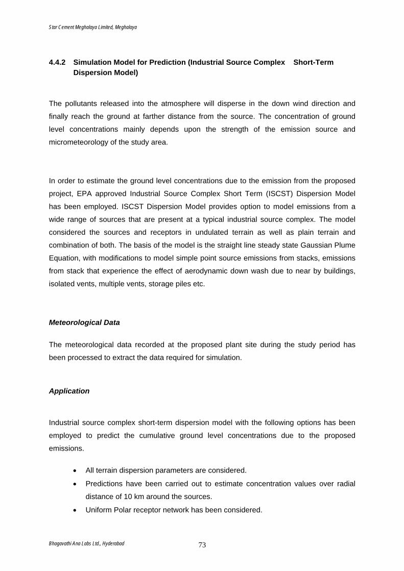
Star Cement Meghalaya Limited, Meghalaya
Bhagavathi Ana Labs Ltd., Hyderabad 73
4.4.2 Simulation Model for Prediction (Industrial Source Complex Short-Term Dispersion Model) The pollutants released into the atmosphere will disperse in the down wind direction and
finally reach the ground at farther distance from the source. The concentration of ground
level concentrations mainly depends upon the strength of the emission source and
micrometeorology of the study area.
In order to estimate the ground level concentrations due to the emission from the proposed
project, EPA approved Industrial Source Complex Short Term (ISCST) Dispersion Model
has been employed. ISCST Dispersion Model provides option to model emissions from a
wide range of sources that are present at a typical industrial source complex. The model
considered the sources and receptors in undulated terrain as well as plain terrain and
combination of both. The basis of the model is the straight line steady state Gaussian Plume
Equation, with modifications to model simple point source emissions from stacks, emissions
from stack that experience the effect of aerodynamic down wash due to near by buildings,
isolated vents, multiple vents, storage piles etc.
Meteorological Data
The meteorological data recorded at the proposed plant site during the study period has
been processed to extract the data required for simulation.
Application
Industrial source complex short-term dispersion model with the following options has been
employed to predict the cumulative ground level concentrations due to the proposed
emissions.
• All terrain dispersion parameters are considered.
• Predictions have been carried out to estimate concentration values over radial
distance of 10 km around the sources.
• Uniform Polar receptor network has been considered.
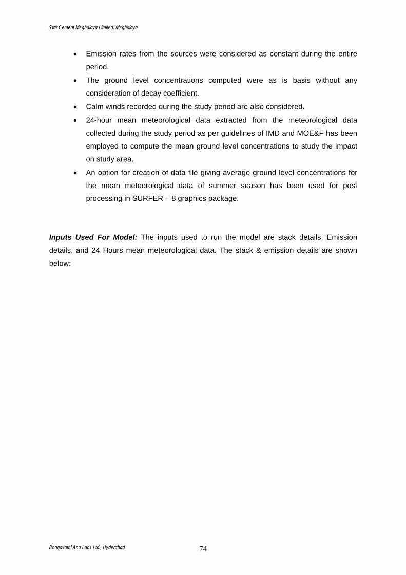
Star Cement Meghalaya Limited, Meghalaya
Bhagavathi Ana Labs Ltd., Hyderabad 74
• Emission rates from the sources were considered as constant during the entire
period.
• The ground level concentrations computed were as is basis without any
consideration of decay coefficient.
• Calm winds recorded during the study period are also considered.
• 24-hour mean meteorological data extracted from the meteorological data
collected during the study period as per guidelines of IMD and MOE&F has been
employed to compute the mean ground level concentrations to study the impact
on study area.
• An option for creation of data file giving average ground level concentrations for
the mean meteorological data of summer season has been used for post
processing in SURFER – 8 graphics package.
Inputs Used For Model: The inputs used to run the model are stack details, Emission
details, and 24 Hours mean meteorological data. The stack & emission details are shown
below:
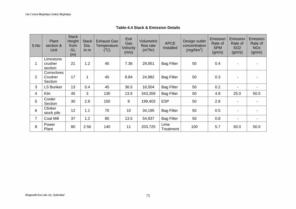
Star Cement Meghalaya Limited, Meghalaya
Bhagavathi Ana Labs Ltd., Hyderabad 75
Table-4.4 Stack & Emission Details
S.No Plant
section & Unit
Stack Height from GL (m)
Stack Dia. in m
Exhaust Gas Temperature
(0C)
Exit Gas
Velocity (m/s)
Volumetric flow rate (m3/hr)
APCE Installed
Design outlet concentration
(mg/Nm3)
Emission Rate of SPM
(gm/s)
Emission Rate of
SO2 (gm/s)
Emission Rate of
NOx (gm/s)
1 Limestone crusher section
21 1.2 45 7.36 29,951 Bag Filter 50 0.4 - -
2 Correctives Crusher Section
17 1 45 8.84 24,982 Bag Filter 50 0.3 - -
3 LS Bunker 13 0.4 45 36.5 16,504 Bag Filter 50 0.2 - -
4 Kiln 45 3 130 13.5 343,359 Bag Filter 50 4.8 25.0 50.0
5 Cooler Section 30 2.8 150 9 199,403 ESP 50 2.8 - -
6 Clinker stock pile 12 1.1 70 10 34,195 Bag Filter 50 0.5 - -
7 Coal Mill 37 1.2 80 13.5 54,937 Bag Filter 50 0.8 - -
8 Power Plant 80 2.56 140 11 203,725 Lime
Treatment 100 5.7 50.0 50.0
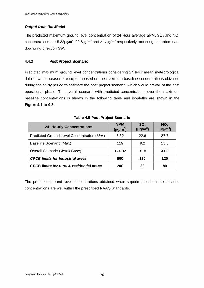
Star Cement Meghalaya Limited, Meghalaya
Bhagavathi Ana Labs Ltd., Hyderabad 76
Output from the Model The predicted maximum ground level concentration of 24 Hour average SPM, SO2 and NOx
concentrations are 5.32µg/m3, 22.6µg/m3 and 27.7µg/m3 respectively occurring in predominant
downwind direction SW.
4.4.3 Post Project Scenario Predicted maximum ground level concentrations considering 24 hour mean meteorological
data of winter season are superimposed on the maximum baseline concentrations obtained
during the study period to estimate the post project scenario, which would prevail at the post
operational phase. The overall scenario with predicted concentrations over the maximum
baseline concentrations is shown in the following table and isopleths are shown in the
Figure 4.1.to 4.3.
Table-4.5 Post Project Scenario
24- Hourly Concentrations SPM (µg/m3)
SO2
(µg/m3) NOX
(µg/m3) Predicted Ground Level Concentration (Max) 5.32 22.6 27.7
Baseline Scenario (Max) 119 9.2 13.3
Overall Scenario (Worst Case) 124.32 31.8 41.0
CPCB limits for Industrial areas 500 120 120
CPCB limits for rural & residential areas 200 80 80 The predicted ground level concentrations obtained when superimposed on the baseline
concentrations are well within the prescribed NAAQ Standards.
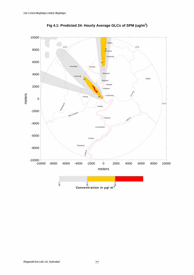
Star Cement Meghalaya Limited, Meghalaya
Bhagavathi Ana Labs Ltd., Hyderabad 77
Fig 4.1: Predicted 24- Hourly Average GLCs of SPM (ug/m3)
-10000 -8000 -6000 -4000 -2000 0 2000 4000 6000 8000 10000
meters
-10000
-8000
-6000
-4000
-2000
0
2000
4000
6000
8000
10000
met
ers
1.00
2.50
4.00
Mynkre
Umrasong
Nongsning
Shiehruphi
Thangskei
Wahiajer
Umbadoh
Lumshnong
Umlaper
Tongseng
Lumtongseng
Sonapur
Shymplong
Umlong
Umrasong
Umrasiang Musiang
Sialkan
Um lu
nar
Lubha R
Lubh
a R
Wah Lanang N
Sesh
ympa
R
25 15 25 15'
25 15'
Concentration in µg/m3
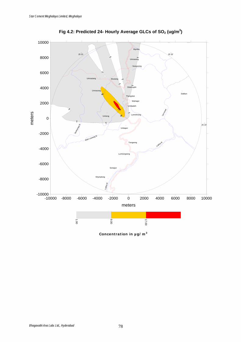
Star Cement Meghalaya Limited, Meghalaya
Bhagavathi Ana Labs Ltd., Hyderabad 78
Fig 4.2: Predicted 24- Hourly Average GLCs of SO2 (ug/m3)
-10000 -8000 -6000 -4000 -2000 0 2000 4000 6000 8000 10000
meters
-10000
-8000
-6000
-4000
-2000
0
2000
4000
6000
8000
10000
met
ers
1.00
9.00
17.00
Mynkre
Umrasong
Nongsning
Shiehruphi
Thangskei
Wahiajer
Umbadoh
Lumshnong
Umlaper
Tongseng
Lumtongseng
Sonapur
Shymplong
Umlong
Umrasong
Umrasiang Musiang
Sialkan
Um lu
nar
Lubha R
Lubh
a R
Wah Lanang N
Sesh
ympa
R
25 15 25 15'
25 15'
Concentration in µg/m3
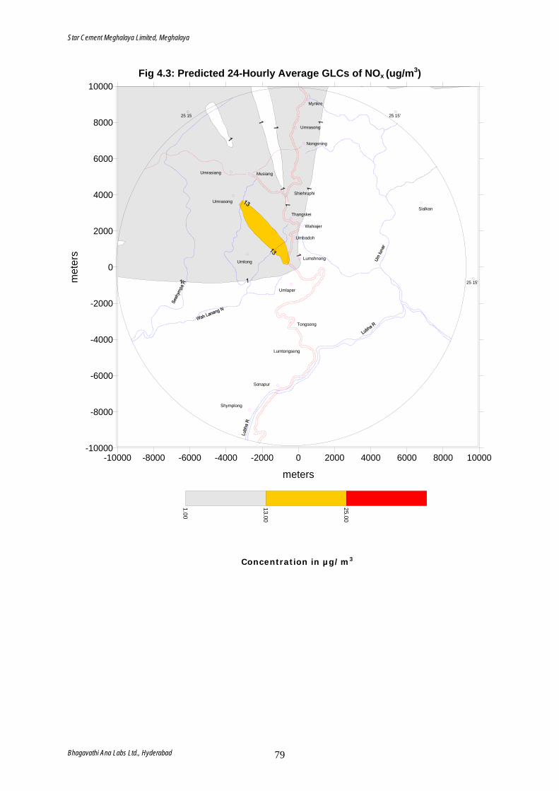
Star Cement Meghalaya Limited, Meghalaya
Bhagavathi Ana Labs Ltd., Hyderabad 79
Fig 4.3: Predicted 24-Hourly Average GLCs of NOx (ug/m3)
-10000 -8000 -6000 -4000 -2000 0 2000 4000 6000 8000 10000
meters
-10000
-8000
-6000
-4000
-2000
0
2000
4000
6000
8000
10000m
eter
s
1.00
13.00
25.00
Mynkre
Umrasong
Nongsning
Shiehruphi
Thangskei
Wahiajer
Umbadoh
Lumshnong
Umlaper
Tongseng
Lumtongseng
Sonapur
Shymplong
Umlong
Umrasong
Umrasiang Musiang
Sialkan
25 15 25 15'
25 15'
Concentration in µg/m3
Star Cement Meghalaya Limited, Meghalaya
Bhagavathi Ana Labs Ltd., Hyderabad 80
4.4.4 Impact of Vehicular Emissions The major emission from the vehicular traffic is carbon monoxide and hydrocarbon. In order
to estimate the incremental rise of HC & CO from the traffic, a vehicular impact assessment
study has been carried out. The following is the estimation of trucks for transport of the iron
ore:
Table 4.6 Estimate of Trucks for Transport
Particular Quantity
Total quantity to be transported, MTPA 4.77 Capacity of each truck (tonnes) 20 Road length (average) 1.0 kms Road width (assumed) 10 mts Atmospheric stability considered for worst case Stable conditions Wind speed (worst case scenario) 1 m/s
From the above table, it can be seen that the total number of truck trips per hour required for
transport of 1.75 MTPA of lime stone will be 70 trips. In order to assess the impacts on the
air environment due to emissions from the trucks, an EPA approved CALINE4 model was
run for the worst meteorological condition considering the total length of the road within the
study area. CALINE4 is a line source air quality models developed by the California
Department of Transportation (Caltrans) and is approved by EPA. It is based on the
Guassian diffusion equation. The model assesses the air quality impacts near road ways.
Given source strength, meteorology and site geometry, CALINE4 can predict pollutant
concentrations for receptors located within 200 meters of the roadway. The following are the
emission rates of various pollutants considered for estimation of impact
Table 4.7 Emissions through transportation
Parameters Emissions Trip length m
Trucks per hour
1000 70 HC & CO 1.5 g/mi
Maximum incremental value of HC & CO has been predicted at a distance of 100 m from the
road with maximum predicted value of 0.2 ppm. The predicted concentration reduces to less
than 0.1 ppm at a distance of 200 m from the road. The impact becomes nil beyond a
distance of 900m.
Star Cement Meghalaya Limited, Meghalaya
Bhagavathi Ana Labs Ltd., Hyderabad 81
4.4.5 Impact on Water Quality
The water requirement for the plant and colony are estimated as 1800 m3/day. The water
requirement for the Captive Power Plant has been estimated as 3116 m3/day. Water is
required for equipment cooling, drinking, sanitation etc. Primarily water requirement for the
unit shall be met from perennial water streams / rivers that are close to the site, such as
Umtargnai, Ummutha, Umlunar and Lubha rivers. A few bore wells in the area also proposed
at different locations within the plant site.
The water distribution system includes an underground raw water tank and a pump house.
The raw water shall be treated in clarifier and in multi grade sand filter followed by
chlorination before sending to consumer points. The water consumed will be recycled after
treatment and shall be utilized in the process. The total Water requirement has been
presented below:
Table 4.8 Water Requirements
Purpose Water Requirement (m3/day) Source
Clinker Unit:
Process 600 Cooling water 525 Dust suppression 125 Domestic at Plant 50 Green belt 50 Colony 450 Total 1800
Power Plant:
Soft water make up 2400 Air Washer system 168 Rejects & blow down 384 Boiler Makeup water 164 Total 3116
Surface water/ Ground water
4.4.6 Impact on Ground Water It is proposed to recycle and reuse the water. Hence the treated wastewater is used for
greenbelt development. SCML adopts the conservation of water policy; hence the water
Star Cement Meghalaya Limited, Meghalaya
Bhagavathi Ana Labs Ltd., Hyderabad 82
drawal will be in accordance to the water conservation policy. Hence the impact of the
project on the ground water and the aquifers from where the water is drawn will be minimal.
4.4.7 Impact on Noise Levels Any industrial complex in general consists of several sources of noise in clusters or single. In
order to predict ambient noise levels at various sensitive areas noise levels were monitored.
Noise levels are mainly generated from plant, boilers, generators, pumps and cooling towers
in the plant. Various equipments like Turbine, Generator, Boilers feed pump, Condensate,
Cooling Tower and ID & FD Fans would be designed to 85 dB (A). Noise levels monitored
are presented below:
Table 4.9 Noise Levels at Different Sources
Name of Source Noise Level at 1 m distance
Mills 86-100 Pumps 85-100 Forced draft fans 85-100 Induced draft fans 77-97 Compressors 82-105 Air Compressor 95 Diesel Generator 75 Coal mill 90
4.4.8 Solid Waste Generation and Impact Solid waste generation is inevitable in any production industry. Safe and scientific
arrangement for handling, storage and disposal of all solid wastes such as fly ash from air
pollution control devices has been planned. Majority of this waste is reused in the cement
manufacturing process.
4.4.9 Impact on Ecology There are no reserved forests located in the close proximity to the plant. The project will not
have adverse impacts on the existing flora and fauna. As the forest is far from the proposed
project, the impact will be minimal. Hence there will not be any severe impact on biodiversity.

Star Cement Meghalaya Limited, Meghalaya
Bhagavathi Ana Labs Ltd., Hyderabad 83
4.4.10 Demography and Socio-economics The impacts of the proposed Cement Plant on demography and socio economic condition
are as follows.
Increase in employment opportunities and Reduction in migrants to outside for
employment.
The project would need total 475 employees.
Increase in literacy rate.
Growth in service sectors
Increase in consumer prices of indigenous produce and services, land prices, house
rent rates and Labour prices.
Improvement in socio cultural environment of the study area.
Improvement in transport, communication, health and educational services.
Increase in employment due to increased business, trade commerce and service
sector.
The overall impact on the socio economic environment will be beneficial.
4.4.11 Impact on Human Settlements Due to the support services requirement of the guest community in the proposed plant, the
host community will be benefited by way of generation of employment opportunities,
increased demand for the local produce and services. Hence, there will be rise in the income
level of the host community.
4.4.12 Impact on Health Adequate air pollution, water and noise control measures will be provided in proposed plant
to conform to regulatory standards. The environmental management and emergency
preparedness plans are proposed to ensure that the probability of undesired events and
consequences are greatly reduced, and adequate mitigation is provided in case of an
emergency. The overall impact on Human health is negligible during operation of plant.

ENVIRONMENTAL MANAGEMENT PLAN
Star Cement Meghalaya Limited, Meghalaya
5.0. ENVIRONMENTAL MANAGEMENT PLAN
5.1 Environmental Management Plan - Introduction M/s Star Cement Meghalaya Limited (SCML), is planning to adopt corporate
philosophy of eco-friendly development. The management firmly believes in the concept
of sustainable industrial operations at all their facilities. To maintain ecological balance of
the area, SCML has proposed to take adequate measures to mitigate all possible
adverse impacts at its proposed new project. SCML has proposed a capital of Rs.13.0
Crores for the Environmental Protection and Social cost for the proposed new project.
SCML has incorporated all necessary steps to mitigate the environmental pollution in the
design stage itself. Environmental Management Plan of the plant details the
environmental quality control measures proposed by SCML during construction and
operations phase of the project. EMP also details the Post Project Monitoring to be
undertaken by the plant authorities in order to maintain environmental quality within the
stipulated standard limits specified by State Pollution Control Board, CPCB and Ministry
of Environment and Forests.
5.2 Environmental Management Plan during Construction Phase 5.2.1 Air Environment The construction of proposed plant would result in the increase of SPM concentrations
due to fugitive dust over a short period. Frequent water sprinkling in the vicinity of the
construction sites would be undertaken and will be continued after the completion of
plant construction, as there is scope for heavy truck mobility. It will be ensured that both
gasoline and diesel powered vehicles are properly maintained to comply with exhaust
emission requirements.
5.2.2 Noise Environment There will be marginal increase in noise levels during construction phase, which is
temporary. No construction activities are planned during night time, which may
contribute to the existing baseline.
Bhagavathi Ana Labs, Hyderabad 84
Star Cement Meghalaya Limited, Meghalaya
5.2.3 Water Environment During construction, all the existing infra-structural services including water supply,
sewage, drainage facilities and electrification will be available for use. The construction
site would be provided with suitable toilet facilities for the workers to allow proper
standards of hygiene. These facilities would be connected to the STP of the operating
unit to minimise impact on the environment.
5.2.4 Land Environment Generally cutting of herbaceous vegetation, during the construction phase results in the
loosening of the top soil. There is no such removal of vegetation in the proposed site.
Further plantation measures would help in preventing soil erosion.
5.2.5 Socio-economic Environment Any construction activity will benefit the local population in a number of ways. The
company management shall give preference to local people through both direct and
indirect employment. It shall provide ample opportunity to the locals to up-lift their living
standards by organizing events that propagate mutual benefits to all, such as health
camps, awareness campaigns, donations to poorer sections of society and
downtrodden. Educational needs of the region should be improved by encouraging the
workers to allow their children to attend schools. Sufficient funds shall be allocated for
these and other emergency needs. Compensation packages to the kin of those workers
who loose / disable their working ability due to any accident.
5.2.6 Safety and Health Adequate space will be provided for construction of temporary sheds for construction
workers mobilized by the contractors. SCML will supply potable water for the
construction workers. The safety department will supervise the safe working of the
contractor and their employees. Work spots will be maintained clean, provided with
optimum lighting and enough ventilation to eliminate dust/fumes. A comprehensive
Occupational Health and Safety management plan is put in place to address any sort of
eventuality.
Bhagavathi Ana Labs, Hyderabad 85
Star Cement Meghalaya Limited, Meghalaya
5.3 Environmental Management Plan during Operations Phase
5.3.1 Air Environment Air pollution is inevitable from the manufacture of cement. The major pollutant emerged
out of operations is particulate matter.
Stack Emissions Management Dust emission is the main pollutant emitted from various stacks in a Cement Plant while
other emissions are SO2, NOx and CO. The following measures are being envisaged to
be adopted:
• Suitably modifications in the ESP/ additional Bag filters are installed downstream of
the stacks which will separate out the incoming dust in flue gas and limit the dust
concentration at its designed outlet concentration of 50 mg/Nm3;
• The dust generated from coal handling plant will be insignificant because of handling
of fine coal in closed circuit. For further suppression of dust adequate water spray
system is being provided;
• In the event of failure of any pollution control equipment, automatic tripping in the
control system is provided;
• For ESP operations, interlocking is provided with supply to electrode, which means
that any distribution in the power supply to electrode will switch the whole unit off;
• A well-designed burner system, shall limit the temperature to a reasonably low value
of NOx. Further it is proposed to go for low NOx Calciner to minimize the NOx
generation and emission;
• Impact of CO emission is negligible in view of the firing technique of keeping a
positive oxygen balance. However, regular monitoring and continuous auto regulation
of fuel and air by automatic combustion control system is proposed to be installed;
• All vehicles and their exhausts would be well maintained and regularly tested for
emission concentration;
• Adequate thickness of insulating material with proper fastening is being provided to
control the thermal pollution;
• Provision of regular preventive maintenance of pollution control equipment; and
Bhagavathi Ana Labs, Hyderabad 86
Star Cement Meghalaya Limited, Meghalaya
• Stack emissions shall be regularly monitored by SCML/ MSPCB/ external agencies on
periodic basis.
Fugitive Emission Management The following measures are being adopted:
• Jet Pulse bag filters at all dry material conveying and transfer points;
• Dust suppression system by water sprinkler at dump hopper of coal/limestone;
• Regular dust suppression with water sprinkler on the haul roads;
• Level sensor to have a gap of only half-meter in between stacking boom and top of
pile;
Tree plantation will be done on more than 33% area of plant and in addition avenue
plantation will be done on both sides of the internal road and near the main office
building as well as at the parking area also.
5.3.2 Noise Environment Some of the design features provided to ensure low noise levels are as per given below:
• All rotating items shall be well lubricated and provided with enclosures as far as
possible to reduce noise transmission. Extensive vibration monitoring system is
being provided to check and reduce vibrations. Vibration isolators are being provided
to reduce vibration and noise wherever possible;
• In general, noise generating items such as fans, blowers, compressors, pumps,
motors etc. are so specified as to limit their speeds to less than 1500 rpm and reduce
noise levels. Static and dynamic balancing of equipment will be insisted upon and
will be verified during inspection and installation;
• Provision of silencers are made wherever possible;
• The insulation provided for prevention of loss of heat and personnel safety shall also
act as noise reducers;
• Layouts of equipment foundations and structures are being designed keeping in view
the requirement of noise abatement;
• Central control room(s) provided for operation and supervision of plant and
equipment will be air-conditioned, insulated and free from plant noise. Necessary
Bhagavathi Ana Labs, Hyderabad 87
Star Cement Meghalaya Limited, Meghalaya
enclosures will also be provided on the working platforms/areas to provide local
protection in high noise level areas;
• Proper lubrication and housekeeping to avoid excessive noise generation;
• In case where the operation of the equipment warrants the presence of operators in
close proximity to equipment, the operators will be provided with necessary safety
and protection equipment such as ear plugs, ear muffs etc.;
• By provision of green belt in and around the plant premises;
• Occupational Health and Safety Administration System (OHSAS) for evaluation of
exposure of noise pollution on the associated staff and comparing it with permissible
exposure and subsequently taking corrective actions shall be developed;
By these measures, it is anticipated that noise levels in the plant will be maintained
below 75 dB(A) at the boundary of the plant premises. Earth mounds and plantations in
the zone between plant and township would further attenuate noise level.
5.3.3 Solid Waste Management
• Waste oil shall be stored in leak proof steel drums and sent to the “Spent Oil Storage
Site”. The waste oil drums shall be properly identified with label of what is contained
both in local language and English. It is proposed to be disposed off by burning it in
the cement kiln under controlled conditions or by selling it to authorized vendors;
• The sludge generated from the STP at colony shall be used as manure for greenbelt
development. Regular monitoring shall be carried out to assess its suitability for
greenbelt development;
• The solid waste generated as municipal waste will be collected, segregated and will
be disposed off through authorized vendors.
• Storage area that would be used for fuel & oil drums and grease cartridges storage
would have concrete flooring;
• Litter, fuel, oil drums, used grease cartridges would be collected and removed
properly;
• Dust bins shall be placed at requisite locations; and
• In case of any spillage, area shall be cordoned off and surface soil shall be removed
and disposed as per standard practice at the earliest.
Bhagavathi Ana Labs, Hyderabad 88
Star Cement Meghalaya Limited, Meghalaya
5.3.4 Water Resource/ Quality Management Following measures shall be adopted:
• Continuous attempt shall be made to optimize/reduce the use of water in plant and
colony;
• Continuous attempt shall be made to avoid wastage and leakage of water;
• Regular record of level and flow of surface water sources shall be maintained;
• Regular record of water table in case of tube wells shall be maintained;
• Raw water quality shall be checked on regular basis for essential parameters under
BIS:10500 before and after treatment;
• Drainage system that shall be used for carrying the waste water to the STP shall be
periodically checked for any leakage; and
• Treated wastewater at inlet and outlet of STP shall be monitored on regular basis to
assess the performance of STP.
5.3.5 Wastewater The wastewater generated from the ongoing operations would typically be from the
water treatment plant rejects and the boiler blowdown. Rejects of the water treatment
plant are neutralized and the blowdown is sent to the common drain pit where it gets
cooled naturally.
5.3.6 Sewage Treatment Plant (STP) Wastewater from the colony would be treated in the Sewage Treatment Plant (STP). The
STP would be designed for maximum hydraulic loading of 200 m3/day. Hence it can
handle the possible sewage generated effectively. The scheme of treatment comprises
of primary, secondary and tertiary treatment. The quality of effluent at inlet and outlet are
as given in below table.
Bhagavathi Ana Labs, Hyderabad 89
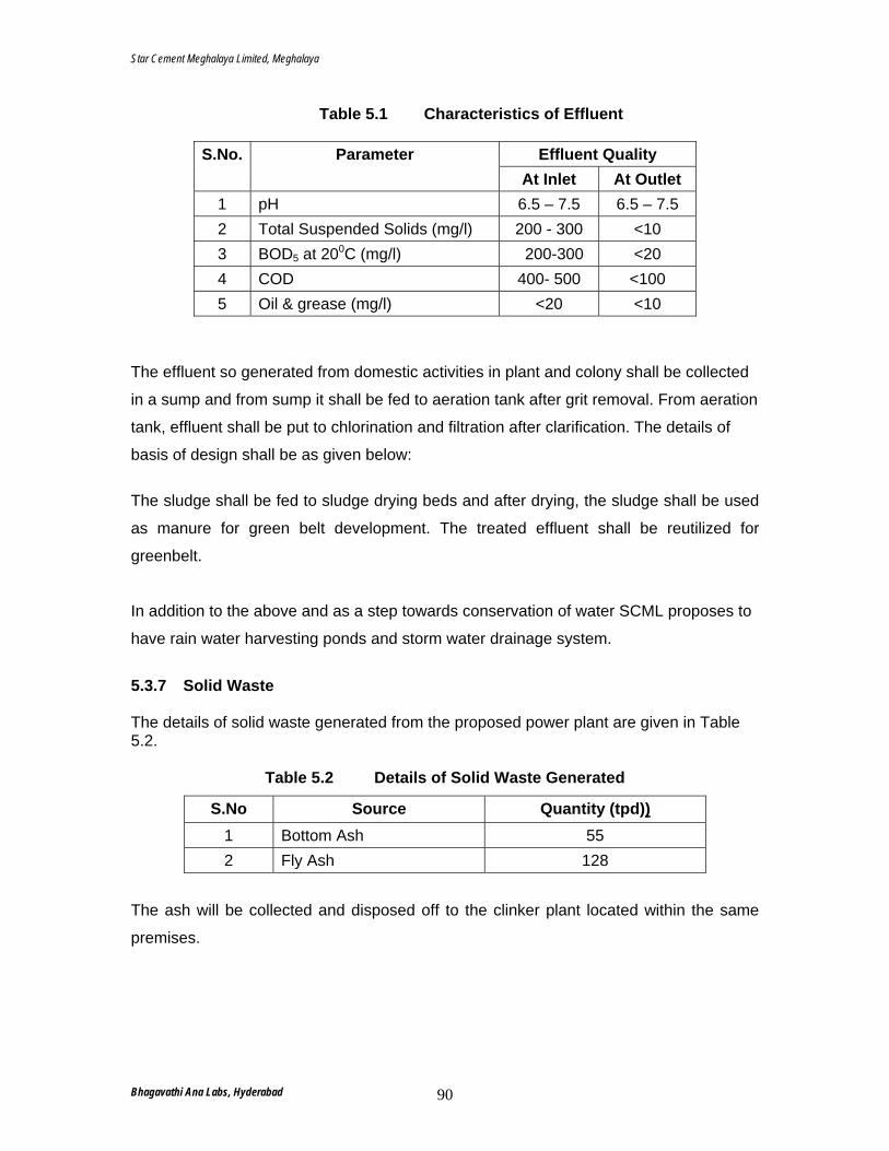
Star Cement Meghalaya Limited, Meghalaya
Table 5.1 Characteristics of Effluent
Effluent Quality S.No. Parameter At Inlet At Outlet
1 pH 6.5 – 7.5 6.5 – 7.5 2 Total Suspended Solids (mg/l) 200 - 300 <10 3 BOD5 at 200C (mg/l) 200-300 <20 4 COD 400- 500 <100 5 Oil & grease (mg/l) <20 <10
The effluent so generated from domestic activities in plant and colony shall be collected
in a sump and from sump it shall be fed to aeration tank after grit removal. From aeration
tank, effluent shall be put to chlorination and filtration after clarification. The details of
basis of design shall be as given below:
The sludge shall be fed to sludge drying beds and after drying, the sludge shall be used
as manure for green belt development. The treated effluent shall be reutilized for
greenbelt.
In addition to the above and as a step towards conservation of water SCML proposes to
have rain water harvesting ponds and storm water drainage system.
5.3.7 Solid Waste The details of solid waste generated from the proposed power plant are given in Table 5.2.
Table 5.2 Details of Solid Waste Generated
S.No Source Quantity (tpd))1 Bottom Ash 55 2 Fly Ash 128
The ash will be collected and disposed off to the clinker plant located within the same
premises.
Bhagavathi Ana Labs, Hyderabad 90
Star Cement Meghalaya Limited, Meghalaya
Waste oil shall be stored in leak proof steel drums and sent to the “Spent Oil Storage
Site”. The waste oil drums shall be properly identified with label of what is contained both
in local language and English. It is proposed to be disposed off by burning it in the
cement kiln under controlled conditions or by selling it to authorized vendors.
The sludge generated from the STP at colony shall be used as manure for greenbelt
development. The solid waste generated from raw water treatment plant shall be
disposed off in leveling low lying patches within the plant and township premises.
However, regular monitoring shall be carried out to assess its suitability for specific
purposes.
The solid waste generated will be collected, segregated and will be disposed off through
authorized vendors.
5.3.8 Housekeeping Salient features of the practices to be adopted are as follows:
• Mechanized cleaning of roads and floor area inside the plant premises by using road
sweeper and mobile vacuum cleaner on regular basis;
• Training on regular basis to all workers and staff about the importance of cleanliness;
• Careful garbage transportation to dumping site and disinfection of transport vehicles
body;
• Decorative plantation to improve aesthetics of the plant; and
• Construction of suitably designed drains all along the roads and boundary of the
plant premises.
5.3.9 Occupational Health & Safety
During cement manufacturing, dust causes the main health hazard. Other health
hazards are due to gas cutting, welding, noise and high temperature and micro ambient
conditions especially near the furnace doors and platforms which may lead to adverse
effects (Heat cramps, heat exhaustion and heat stress reaction) leading to local and
systemic disorders. Injuries in cement industries are usually of minor natures like
bruises, cuts, and abrasion because of manual handling. However, serious accidents
Bhagavathi Ana Labs, Hyderabad 91
Star Cement Meghalaya Limited, Meghalaya
due to common reasons like fall from height and entrapment of limbs in machinery are
possible.
The precautionary measures which shall be followed to reduce the risk due to dust on
the workers engaged in and around the material handling areas are:
• Adequate arrangements are made for preventing the generation of dust by providing
the chutes at transfer points to reduce the falling height of material, preventing
spillage of material by maintaining the handling equipment, isolating the high dust
generating areas by enclosing them in appropriate housing and appropriately
dedusting through high efficiency bag filters;
• Due care shall be taken to maintain continuous water supply in the water spraying
system and all efforts would be made to suppress the dust generated by coal
handling system by water spraying at appropriate points;
• Almost all material handling systems are automatic i.e. unmanned. The workers
engaged in material handling system shall be provided with personal protective
equipment like dust masks, respirators, helmets, face shields etc;
• All workers engaged in material handling system shall be regularly examined for lung
diseases;
• Any worker found to develop symptoms of dust related diseases shall be changed
over to other jobs in cleaner areas; and
• Thermal insulation is being provided wherever necessary to minimize heat radiation
from the equipment, piping, etc. to ensure protection of workers. Insulation is being
done by adequate cleats, wire nets, jackets etc. to avoid loosening. Insulation
thickness is so selected that the covering jacket surface temperature does not
exceed the surrounding ambient temperature by more than 15oC. The effect of
thermal pollution of air will be negligible considering the atmosphere as the ultimate
heat sink and no other industry being located in the vicinity.
5.3.10 Measures to Improve Socio-Economic Conditions In addition to payment of additional royalty, sales tax and excise duty to the
Government, SCML shall continue its efforts to improve the socio-economic status of the
local habitants. Preference shall be given to locals for any direct and indirect
employment based on the availability of skills as required.
Bhagavathi Ana Labs, Hyderabad 92
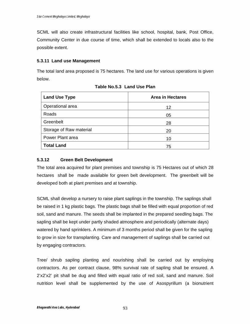
Star Cement Meghalaya Limited, Meghalaya
SCML will also create infrastructural facilities like school, hospital, bank, Post Office,
Community Center in due course of time, which shall be extended to locals also to the
possible extent.
5.3.11 Land use Management The total land area proposed is 75 hectares. The land use for various operations is given
below.
Table No.5.3 Land Use Plan
Land Use Type Area in Hectares
Operational area 12 Roads 05 Greenbelt 28 Storage of Raw material 20 Power Plant area 10 Total Land 75
5.3.12 Green Belt Development The total area acquired for plant premises and township is 75 Hectares out of which 28
hectares shall be made available for green belt development. The greenbelt will be
developed both at plant premises and at township.
SCML shall develop a nursery to raise plant saplings in the township. The saplings shall
be raised in 1 kg plastic bags. The plastic bags shall be filled with equal proportion of red
soil, sand and manure. The seeds shall be implanted in the prepared seedling bags. The
sapling shall be kept under partly shaded atmosphere and periodically (alternate days)
watered by hand sprinklers. A minimum of 3 months period shall be given for the sapling
to grow in size for transplanting. Care and management of saplings shall be carried out
by engaging contractors.
Tree/ shrub sapling planting and nourishing shall be carried out by employing
contractors. As per contract clause, 98% survival rate of sapling shall be ensured. A
2’x2’x2’ pit shall be dug and filled with equal ratio of red soil, sand and manure. Soil
nutrition level shall be supplemented by the use of Asospyrillum (a bionutrient
Bhagavathi Ana Labs, Hyderabad 93
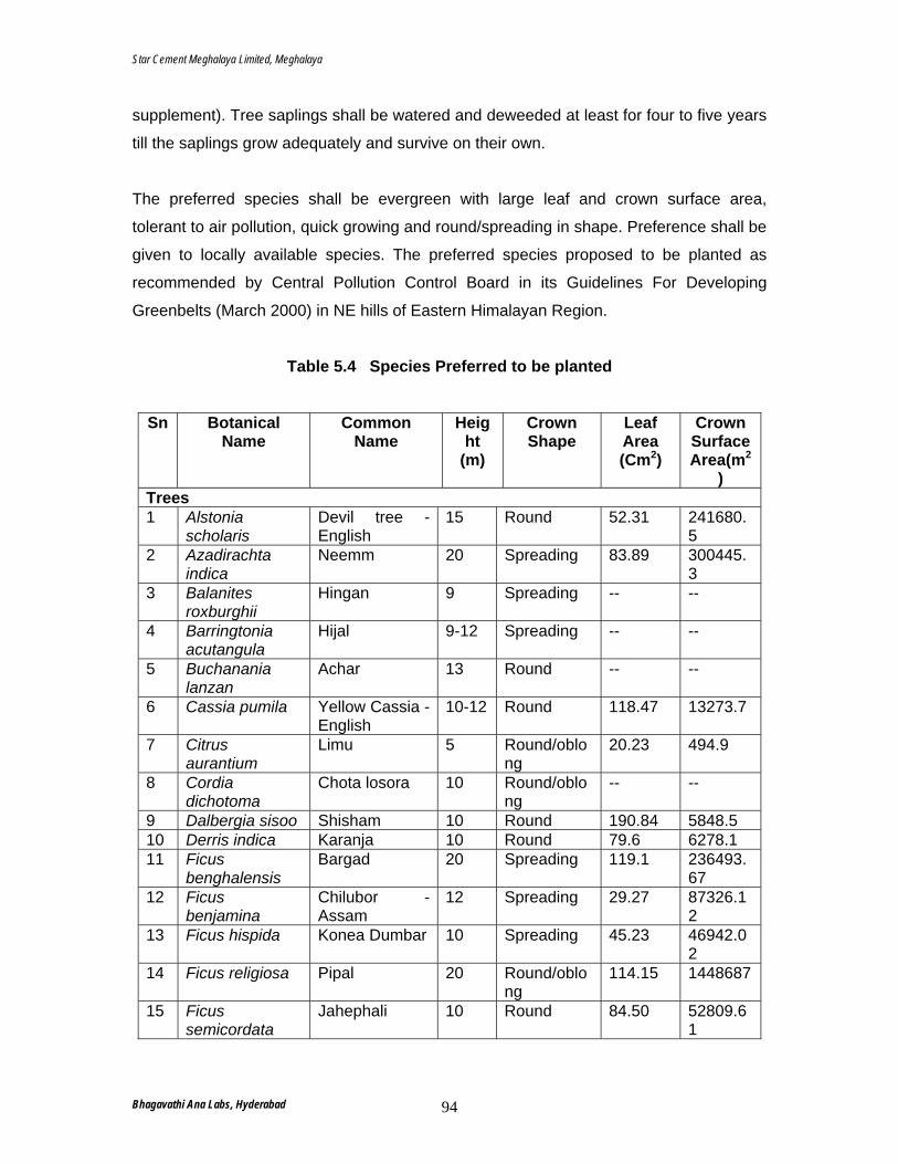
Star Cement Meghalaya Limited, Meghalaya
supplement). Tree saplings shall be watered and deweeded at least for four to five years
till the saplings grow adequately and survive on their own.
The preferred species shall be evergreen with large leaf and crown surface area,
tolerant to air pollution, quick growing and round/spreading in shape. Preference shall be
given to locally available species. The preferred species proposed to be planted as
recommended by Central Pollution Control Board in its Guidelines For Developing
Greenbelts (March 2000) in NE hills of Eastern Himalayan Region.
Table 5.4 Species Preferred to be planted
Sn Botanical Name
Common Name
Height
(m)
Crown Shape
Leaf Area (Cm2)
Crown Surface Area(m2
) Trees 1 Alstonia
scholaris Devil tree - English
15 Round 52.31 241680.5
2 Azadirachta indica
Neemm 20 Spreading 83.89 300445.3
3 Balanites roxburghii
Hingan 9 Spreading -- --
4 Barringtonia acutangula
Hijal 9-12 Spreading -- --
5 Buchanania lanzan
Achar 13 Round -- --
6 Cassia pumila Yellow Cassia - English
10-12 Round 118.47 13273.7
7 Citrus aurantium
Limu 5 Round/oblong
20.23 494.9
8 Cordia dichotoma
Chota losora 10 Round/oblong
-- --
9 Dalbergia sisoo Shisham 10 Round 190.84 5848.5 10 Derris indica Karanja 10 Round 79.6 6278.1 11 Ficus
benghalensis Bargad 20 Spreading 119.1 236493.
67 12 Ficus
benjamina Chilubor - Assam
12 Spreading 29.27 87326.12
13 Ficus hispida Konea Dumbar 10 Spreading 45.23 46942.02
14 Ficus religiosa Pipal 20 Round/oblong
114.15 1448687
15 Ficus semicordata
Jahephali 10 Round 84.50 52809.61
Bhagavathi Ana Labs, Hyderabad 94
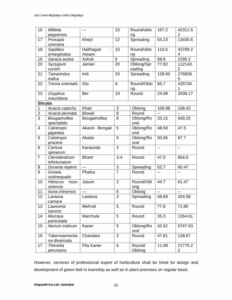
Star Cement Meghalaya Limited, Meghalaya
16 Milletia peguensis
--- 10 Round/oblong
167.2 42311.52
17 Prosopis cineraria
Khejri 12 Spreading 54.23 13430.6
18 Sapildus emarginatus
Haithaguti - Assam
10 Round/oblong
110.6 43789.24
19 Saraca asoka Ashok 5 Spreading 68.8 2295.2 20 Syzygium
cumini Jaman 20 Oblong/Spr
eading 77.82 112143.
2 21 Tamarindus
indica Imli 20 Spreading 128.60 276839.
5 22 Trema orientalis Gio 6 Round/Oblo
ng 65.7 425734.
1 23 Zizyphus
mauritiana Ber 10 Round 24.08 2638.17
Shrubs 1 Acacia catechu Khair 3 Oblong 109.98 108.42 2 Acacia pennata Biswal 8 Round -- -- 3 Bougainvillea
spectabilis Bougainvillea 8 Oblong/Ro
und 33.15 939.25
4 Calotropis gigantea
Akand - Bengali 5 Oblong/Round
48.58 47.5
5 Calotropis procera
Akada 6 Oblong/Round
50.06 87.7
6 Carissa spinarum
Karaunda 3 Round -- --
7 Clerodendrum infortunatum
Bhant 3-4 Round 47.9 854.0
8 Duranta repens --- 3 Spreading 62.7 60.47 9 Grewia
subinequalis Phalsa 7 Round -- --
10 Hibiscus rosa-sinensis
Jasum 3 Round/Oblong
44.7 61.47
11 Ixora chinensis --- 6 Oblong -- -- 12 Lantana
camara Lantana 3 Spreading 48.69 324.58
13 Lawsonia inermis
Mehndi 5 Round 77.8 71.85
14 Murraya paniculata
Marchula 5 Round 35.3 1354.61
15 Nerium indicum Kaner 5 Oblong/Round
32.62 5747.63
16 Tabernaemontana divaricata
Chandani 3 Round 47.81 128.67
17 Thevetia peruviana
Pila Kaner 6 Round/ Oblong
11.08 21775.22
However, services of professional expert of horticulture shall be hired for design and
development of green belt in township as well as in plant premises on regular basis.
Bhagavathi Ana Labs, Hyderabad 95
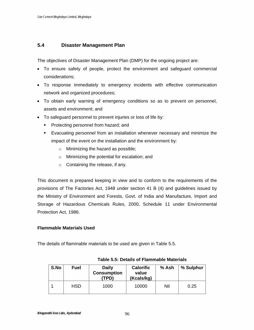
Star Cement Meghalaya Limited, Meghalaya
5.4 Disaster Management Plan
The objectives of Disaster Management Plan (DMP) for the ongoing project are:
• To ensure safety of people, protect the environment and safeguard commercial
considerations;
• To response immediately to emergency incidents with effective communication
network and organized procedures;
• To obtain early warning of emergency conditions so as to prevent on personnel,
assets and environment; and
• To safeguard personnel to prevent injuries or loss of life by:
Protecting personnel from hazard; and
Evacuating personnel from an installation whenever necessary and minimize the
impact of the event on the installation and the environment by:
o Minimizing the hazard as possible;
o Minimizing the potential for escalation; and
o Containing the release, if any.
This document is prepared keeping in view and to conform to the requirements of the
provisions of The Factories Act, 1948 under section 41 B (4) and guidelines issued by
the Ministry of Environment and Forests, Govt. of India and Manufacture, Import and
Storage of Hazardous Chemicals Rules, 2000, Schedule 11 under Environmental
Protection Act, 1986.
Flammable Materials Used The details of flammable materials to be used are given in Table 5.5.
Table 5.5: Details of Flammable Materials
S.No Fuel Daily Consumption
(TPD)
Calorific value
(Kcals/kg)
% Ash % Sulphur
1 HSD 1000 10000 Nil 0.25
Bhagavathi Ana Labs, Hyderabad 96
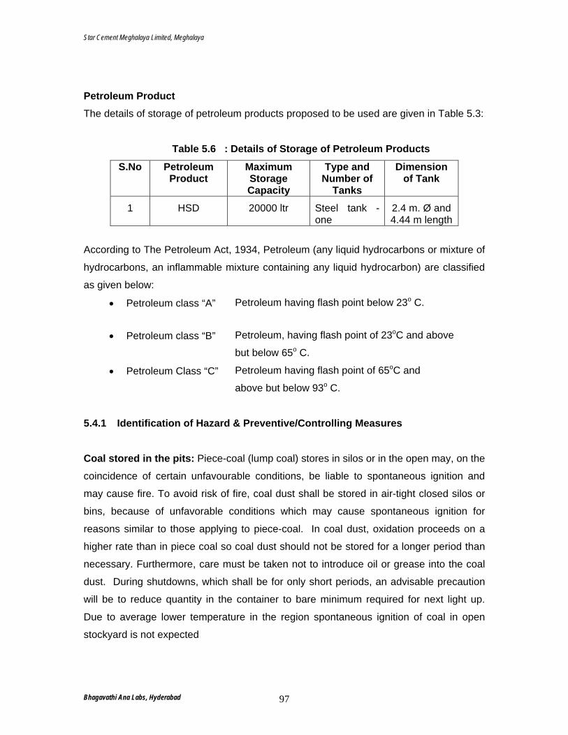
Star Cement Meghalaya Limited, Meghalaya
Petroleum Product The details of storage of petroleum products proposed to be used are given in Table 5.3:
Table 5.6 : Details of Storage of Petroleum Products
S.No Petroleum Product
Maximum Storage Capacity
Type and Number of
Tanks
Dimension of Tank
1 HSD 20000 ltr Steel tank - one
2.4 m. Ø and 4.44 m length
According to The Petroleum Act, 1934, Petroleum (any liquid hydrocarbons or mixture of
hydrocarbons, an inflammable mixture containing any liquid hydrocarbon) are classified
as given below:
• Petroleum class “A” Petroleum having flash point below 23o C.
• Petroleum class “B” Petroleum, having flash point of 23oC and above
but below 65o C.
• Petroleum Class “C” Petroleum having flash point of 65oC and
above but below 93o C.
5.4.1 Identification of Hazard & Preventive/Controlling Measures Coal stored in the pits: Piece-coal (lump coal) stores in silos or in the open may, on the
coincidence of certain unfavourable conditions, be liable to spontaneous ignition and
may cause fire. To avoid risk of fire, coal dust shall be stored in air-tight closed silos or
bins, because of unfavorable conditions which may cause spontaneous ignition for
reasons similar to those applying to piece-coal. In coal dust, oxidation proceeds on a
higher rate than in piece coal so coal dust should not be stored for a longer period than
necessary. Furthermore, care must be taken not to introduce oil or grease into the coal
dust. During shutdowns, which shall be for only short periods, an advisable precaution
will be to reduce quantity in the container to bare minimum required for next light up.
Due to average lower temperature in the region spontaneous ignition of coal in open
stockyard is not expected
Bhagavathi Ana Labs, Hyderabad 97
Star Cement Meghalaya Limited, Meghalaya
Coal stored while firing: When pulverized coal is fired in kiln through burner at burner
platform, chances of explosion or backfire cannot be ruled out.
The following measures shall be adopted to prevent/control hazards associate with coal
handling during operation:
• Adequate number of DCP & CO2 fire extinguishers shall be provided in all vantage
points in the plant;
• All apparatus and conveying lines coming in to contact with pulverized coal shall be
earthed to avoid electrostatic charging;
• Regular monitoring of temperature in the bins;
• Storing limestone dust and sand near bins;
• Provision of pressurized water hydrant;
• Presence of an active safety committee which meets once in a month;
• Provision of security personnel round the clock;
• Provision of flow of water into the coal pit to cool down the temperature; and
• Small coal heaps shall be maintained in coal pit.
Petroleum products: Since fuel oil is a combustible liquid, so most likely hazard is the
fire hazard.
The following measures shall be adopted to prevent/control hazards associate with fuel
oil handling:
• Oil carrying pipes shall be properly insulated with standard hose pipe connections;
• Pumping stations shall be located away from the tanks;
• Provision of well laid out Fire Hydrant System comprising of a water pipeline
network, adequate number of hydrants and monitor points for fire fighting
• Provision of static water reservoir;
• Adequate number of DCP and CO2 Fire extinguishers shall be provided at all
vantage points in the plant;
• Provision of electrical & hand operated sirens at convenient location inside the plant;
• Adequate number of breathers shall be provided at the top of storage tanks;
• Adequate earthing and bonding shall be provided in all storage tanks, handling
machinery and structures, electrical motors;
• Flame-proof electrical fittings shall be provided in storage area;
Bhagavathi Ana Labs, Hyderabad 98
Star Cement Meghalaya Limited, Meghalaya
• Presence of an active safety committee which meets once in a month;
• The surrounding area of the tank & plant shall be always kept clear;
• Standard hose pipe connects shall be always maintained;
• Only authorized persons shall be allowed inside storage area;
• Good Housekeeping shall be strictly maintained;
• No weeds, grass and combustible material in and around the fenced area;
• Adequate lighting in the workplace;
• Use of non-sparking tools and also the right tools for maintenance job
• NO SMOKING signs displayed;
• FIRE SUB-STATION shall be equipped with all accessories such as fire
extinguishers, fire hoses, water tank, one diesel operated fire fighting pump at the oil
storage tank area;
• Free access to hydrant point;
• Mock drills shall be conducted periodically;
• Provision of Security Personnel round the clock at the storage area;
• Leakage of oil shall be prevented and leaked oil if any shall be regularly cleaned by
using saw dust and sand; and
• Oil leakage during oil unloading shall be collected in a pit and transferred to storage
tanks back by pumping.
Specific Hazards
• Pool fire may occur due to accumulation of oil in the oil pit/oil drains. Sand bath
shall be provided at the vulnerable points and adequate number of DCP and CO2
fire extinguishers shall be provided at all vantage points;
• Tank fire may occur due to a) Thunder stroke, b) Short circuit and c) Over
pressurization. Following preventive/ controlling measures shall be put in place:
a) Lightning arrestors shall be provided to the tanks;
b) Flame-proof electrical fittings shall be provided in the storage area;
c) Proper earthing and bonding shall be provided in all storage tanks, handling
machinery and structure, electrical motors; and
d) In case of fire, effort shall be made to shut off all the operation and fire is to
be extinguished under controlled condition.
Bhagavathi Ana Labs, Hyderabad 99
Star Cement Meghalaya Limited, Meghalaya
• DG bursting of gland followed with fire. Effort should be made to shut off source of
fuel and the fire shall be extinguished under controlled condition.
5.4.2 Main Component of the On-Site Disaster Management Plan
Disaster Management Plan does not cover the natural disaster and sabotage activities.
However, duties and responsibilities given in this DMP may be followed to deal with
emergencies, arising out of natural disasters and subrogate activities. The main
components of disaster management plan are as follows:
Emergency Response Organization
Following officers of the plant will be responsible for coordination, in case of emergency
situation in any section of the cement plant:
• Head of Project at Site : Site Controller
• Head-Operation (HOD) : Incident Controller
• Employee who give the first information
about the incident/ accident
: Primary Controller
• Head-Personnel : Liaison Officer
• In-Charge of Security Personnel : Emergency/ Communication Officer
• Medical Officer Responsibility of Key Personnel Site Controller Head of the Project at site or his deputy will assume overall responsibility. As soon as he
is informed of the emergency, he shall proceed to the Emergency Control Center (ECC)
and his duties shall be:
• To assess the magnitude of the incident and decide if employees need to be
evacuated from assembly points;
• To maintain continuous review of possible development and to assess in
consultation with Incident Controller as to whether the shutting down the plant or part
of plant and evacuation of person is required;
• To exercise direct operational control over the areas other than affected;
Bhagavathi Ana Labs, Hyderabad 100
Star Cement Meghalaya Limited, Meghalaya
• To give necessary instructions to Liaison officer and Emergency officer regarding the
help to be obtained from out side agencies like fire brigade, police and medical;
• To advice liaison officer to pass necessary information about the incident to news
media and ensure that the evidences are preserved for inquiries to be conducted by
statutory authorities;
• To liaison with senior officials of Police, Fire, Medical, MSPCB and Factory
Inspectorate; and
• To issue authorized statement to news media.
In Case of Accident During the time of any accident or emergency condition, the person present at site shall
has to inform the Shift In-Charge immediately which shall be followed by:
• Shift In-Charge will inform to respective Department Head, Time Office and Security
Personnel;
• According to the seriousness of the accident, the Department Head will arrange duty
doctors, ambulance and inform the personnel department;
• The department head will immediately report to spot and collect the cause of
accident;
• The department head will make a final report;
• The cause of accident shall be analyzed and rehabilitation measure shall be
implemented; and
• The workmen shall be advised to do the work with more safety measures.
Emergency Shutdown Procedure If necessary, full or partial shut down of the plant shall be followed under the judgment of
the Incident Controller or the Site controller. On hearing the emergency siren/message
over phone, the following procedure will be followed to shutdown the plant.
• The operation/ maintenance department will stop incoming and outgoing petroleum
product supply or coal supply;
• If the unloading of petroleum products/ Coal is in progress that will be stopped and
vehicle/tanker will be sent out of the area;
• Head (Operations) will stop all the production/ maintenance activity if necessary;
Bhagavathi Ana Labs, Hyderabad 101
Star Cement Meghalaya Limited, Meghalaya
• Loading of cement will be stopped and the vehicles will be sent out; and
• The individuals designated for the emergency preparedness will carry out the work
as assigned to him as per the checklist.
Medical Facility Available at SCML: The focus of medical facilities shall be to:
• Equip the hospital/ health center with necessary equipment/ medicines;
• To keep the blood group record of all the employees;
• To train the Doctors for handling emergency situation/ casualties;
• To keep liaison with city hospitals and other hospitals in the area; and
• To keep the list of the blood donors ready.
Keeping in view the above requirement, SCML shall have full fledged Dispensary at the
Plant. Full time doctor, Nurses, paramedical staff, laboratory staff and attendants shall
be employed. Ambulance facility is also proposed to be provided.
Post Emergency Activities
Post emergency activities comprise of steps taken after the emergency is
over so as to establish the reasons of the causation of the emergency and
preventive measures. The steps involved are:
• Collection of records;
• Conducting inquiry and concluding preventive measures;
• Making insurance claims;
• Preparation of inquiry reports with recommendations;
• Rehabilitate the affected persons within the plant and outside the plant;
and
• To restart the plant.
Off – Site Emergency Plan
As per identified hazards, the possibility of “offsite” emergency situation are
ruled out, as SCML is not likely to pose any off site emergency. Hence this
plant does not call for any preparation of an off site emergency plan.
Bhagavathi Ana Labs, Hyderabad 102
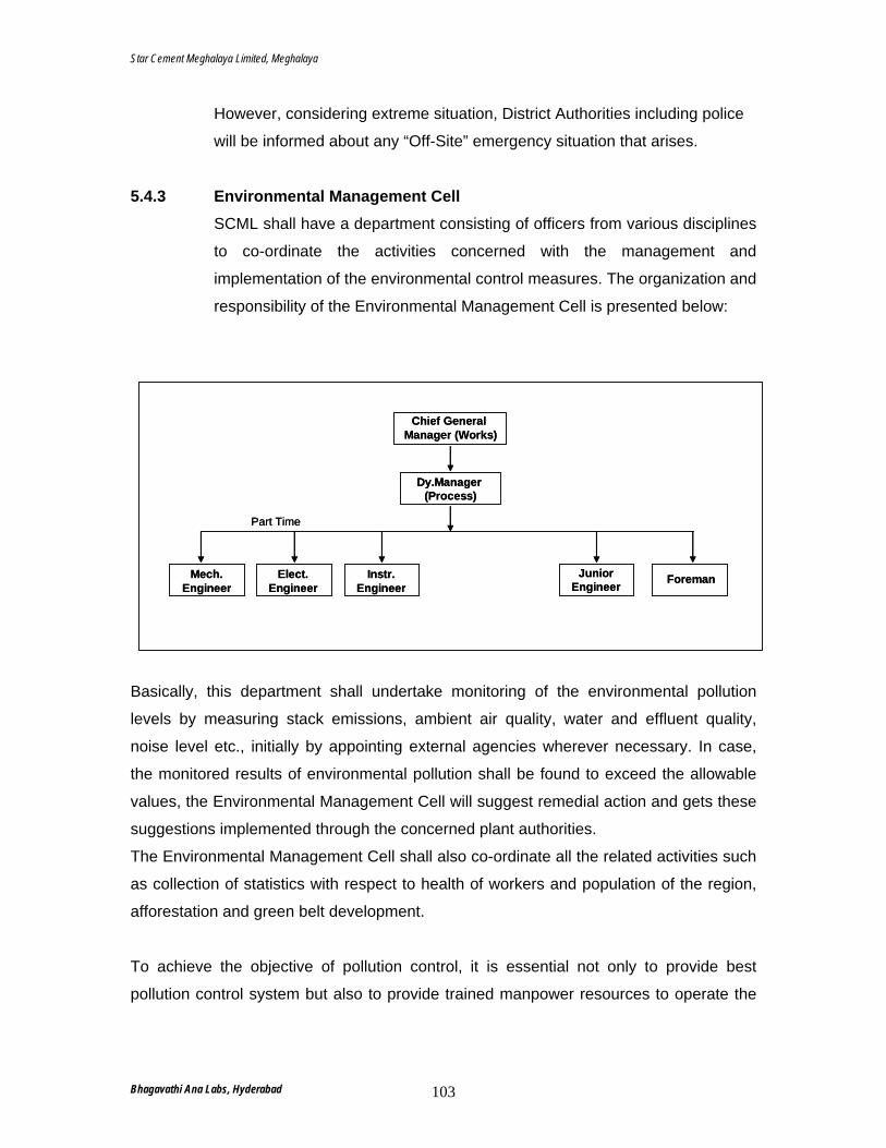
Star Cement Meghalaya Limited, Meghalaya
However, considering extreme situation, District Authorities including police
will be informed about any “Off-Site” emergency situation that arises. 5.4.3 Environmental Management Cell
SCML shall have a department consisting of officers from various disciplines
to co-ordinate the activities concerned with the management and
implementation of the environmental control measures. The organization and
responsibility of the Environmental Management Cell is presented below:
Dy.Manager (Process)
Chief General Manager (Works)
Mech.Engineer
Elect.Engineer
Instr.Engineer
JuniorEngineer Foreman
Part Time
Dy.Manager (Process)
Chief General Manager (Works)
Mech.Engineer
Elect.Engineer
Instr.Engineer
JuniorEngineer Foreman
Part Time
Basically, this department shall undertake monitoring of the environmental pollution
levels by measuring stack emissions, ambient air quality, water and effluent quality,
noise level etc., initially by appointing external agencies wherever necessary. In case,
the monitored results of environmental pollution shall be found to exceed the allowable
values, the Environmental Management Cell will suggest remedial action and gets these
suggestions implemented through the concerned plant authorities.
The Environmental Management Cell shall also co-ordinate all the related activities such
as collection of statistics with respect to health of workers and population of the region,
afforestation and green belt development.
To achieve the objective of pollution control, it is essential not only to provide best
pollution control system but also to provide trained manpower resources to operate the
Bhagavathi Ana Labs, Hyderabad 103
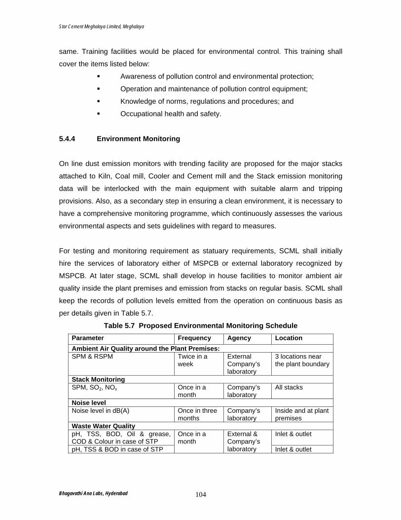
Star Cement Meghalaya Limited, Meghalaya
same. Training facilities would be placed for environmental control. This training shall
cover the items listed below:
Awareness of pollution control and environmental protection;
Operation and maintenance of pollution control equipment;
Knowledge of norms, regulations and procedures; and
Occupational health and safety.
5.4.4 Environment Monitoring
On line dust emission monitors with trending facility are proposed for the major stacks
attached to Kiln, Coal mill, Cooler and Cement mill and the Stack emission monitoring
data will be interlocked with the main equipment with suitable alarm and tripping
provisions. Also, as a secondary step in ensuring a clean environment, it is necessary to
have a comprehensive monitoring programme, which continuously assesses the various
environmental aspects and sets guidelines with regard to measures.
For testing and monitoring requirement as statuary requirements, SCML shall initially
hire the services of laboratory either of MSPCB or external laboratory recognized by
MSPCB. At later stage, SCML shall develop in house facilities to monitor ambient air
quality inside the plant premises and emission from stacks on regular basis. SCML shall
keep the records of pollution levels emitted from the operation on continuous basis as
per details given in Table 5.7.
Table 5.7 Proposed Environmental Monitoring Schedule Parameter Frequency Agency Location Ambient Air Quality around the Plant Premises: SPM & RSPM Twice in a
week External Company’s laboratory
3 locations near the plant boundary
Stack Monitoring SPM, SO2, NOx Once in a
month Company’s laboratory
All stacks
Noise level Noise level in dB(A) Once in three
months Company’s laboratory
Inside and at plant premises
Waste Water Quality pH, TSS, BOD, Oil & grease, COD & Colour in case of STP
Inlet & outlet
pH, TSS & BOD in case of STP
Once in a month
External & Company’s laboratory Inlet & outlet
Bhagavathi Ana Labs, Hyderabad 104

Star Cement Meghalaya Limited, Meghalaya
In addition to above:
• Detailed analysis of treated wastewater shall be carried out for the parameters as
specified in Schedule II by MOEF to assess its suitability for greenbelt development
once in three months; and
• Detailed analysis of sludge from the STP shall also be carried out once in a year for
their suitability to be used as manure.
Bhagavathi Ana Labs, Hyderabad 105
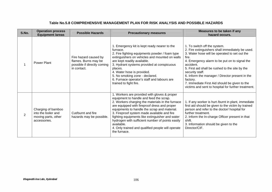
Table No.5.8 COMPREHENSIVE MANAGEMENT PLAN FOR RISK ANALYSIS AND POSSIBLE HAZARDS
S.No. Operation process Equipment /areas Possible Hazards Precautionary measures Measures to be taken if any
hazard occurs.
1 Power Plant
Fire hazard caused by flames. Burns may be possible if directly coming in contact.
1. Emergency kit is kept ready nearer to the furnace. 2. Fire fighting equipments powder / foam type extinguishers on vehicles and mounted on walls are kept readily available. 3. Hydrant systems provided at conspicuous places. 4. Water hose is provided. 5. No smoking zone - declared. 6. Furnace operator’s staff and labours are trained to fight fire.
1. To switch off the system. 2. Fire extinguishers shall immediately be used. 3. Water hose will be operated to set out the fire. 4. Emergency alarm to be put on to signal the accident. 5. First aid shall be rushed to the site by the security staff. 6. Inform the manager / Director present in the factory. 7. Immediate First Aid should be given to the victims and sent to hospital for further treatment.
2
Charging of bamboo into the boiler and moving parts, other accessories.
Cut/burnt and fire hazards may be possible.
1. Workers are provided with gloves & proper equipment to handle and feed the scrap. 2. Workers charging the materials in the furnace are equipped with fireproof dress and proper equipments to handle the scrap and material. 3. Fireproof system made available and fire fighting equipments like extinguisher and water hydrogen with sufficient number of points easily available. 4. Only trained and qualified people will operate the furnace.
1. If any worker is hurt /burnt in plant, immediate first aid should be given to the victim by trained person and refer to the doctor/ hospital for further treatment. 2. Inform the In-charge Officer present in that shift. 3. Information should be given to the Director/CIF.
Bhagavathi Ana Labs, Hyderabad 106
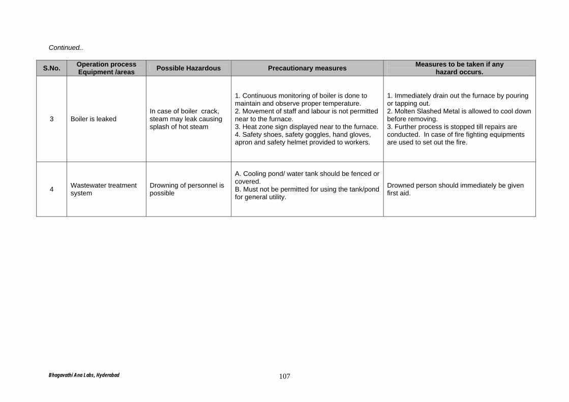
Continued..
S.No. Operation process Equipment /areas Possible Hazardous Precautionary measures Measures to be taken if any
hazard occurs.
3 Boiler is leaked In case of boiler crack, steam may leak causing splash of hot steam
1. Continuous monitoring of boiler is done to maintain and observe proper temperature. 2. Movement of staff and labour is not permitted near to the furnace. 3. Heat zone sign displayed near to the furnace. 4. Safety shoes, safety goggles, hand gloves, apron and safety helmet provided to workers.
1. Immediately drain out the furnace by pouring or tapping out. 2. Molten Slashed Metal is allowed to cool down before removing. 3. Further process is stopped till repairs are conducted. ln case of fire fighting equipments are used to set out the fire.
4 Wastewater treatment system
Drowning of personnel is possible
A. Cooling pond/ water tank should be fenced or covered. B. Must not be permitted for using the tank/pond for general utility.
Drowned person should immediately be given first aid.
Bhagavathi Ana Labs, Hyderabad 107
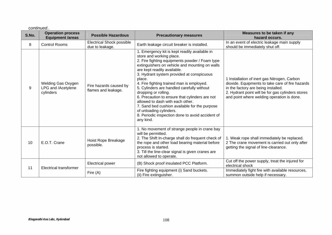
continued.. S.No. Operation process
Equipment /areas Possible Hazardous Precautionary measures Measures to be taken if any hazard occurs.
8 Control Rooms Electrical Shock possible due to leakage. Earth leakage circuit breaker is installed. In an event of electric leakage main supply
should be immediately shut off.
9 Welding Gas Oxygen LPG and /Acetylene cylinders
Fire hazards caused by flames and leakage.
1. Emergency kit is kept readily available in store and working place. 2. Fire fighting equipments powder / Foam type extinguishers on vehicle and mounting on walls are kept readily available. 3. Hydrant system provided at conspicuous place. 4. Fire fighting trained man is employed. 5. Cylinders are handled carefully without dropping or rolling. 6. Precaution to ensure that cylinders are not allowed to dash with each other. 7. Sand bed cushion available for the purpose of unloading cylinders. 8. Periodic inspection done to avoid accident of any kind.
1 Installation of inert gas Nitrogen, Carbon dioxide. Equipments to take care of fire hazards in the factory are being installed. 2. Hydrant point will be for gas cylinders stores and point where welding operation is done.
10 E.O.T. Crane Hoist Rope Breakage possible.
1. No movement of strange people in crane bay will be permitted. 2. The Shift In-charge shall do frequent check of the rope and other load bearing material before process is started. 3. Till the line-clear signal is given cranes are not allowed to operate.
1. Weak rope shall immediately be replaced. 2 The crane movement is carried out only after getting the signal of line-clearance.
Electrical power (B) Shock proof insulated PCC Platform. Cut off the power supply, treat the injured for electrical shock 11 Electrical transformer
Fire (A) Fire fighting equipment (i) Sand buckets. (ii) Fire extinguisher.
Immediately fight fire with available resources, summon outside help if necessary.
Bhagavathi Ana Labs, Hyderabad 108
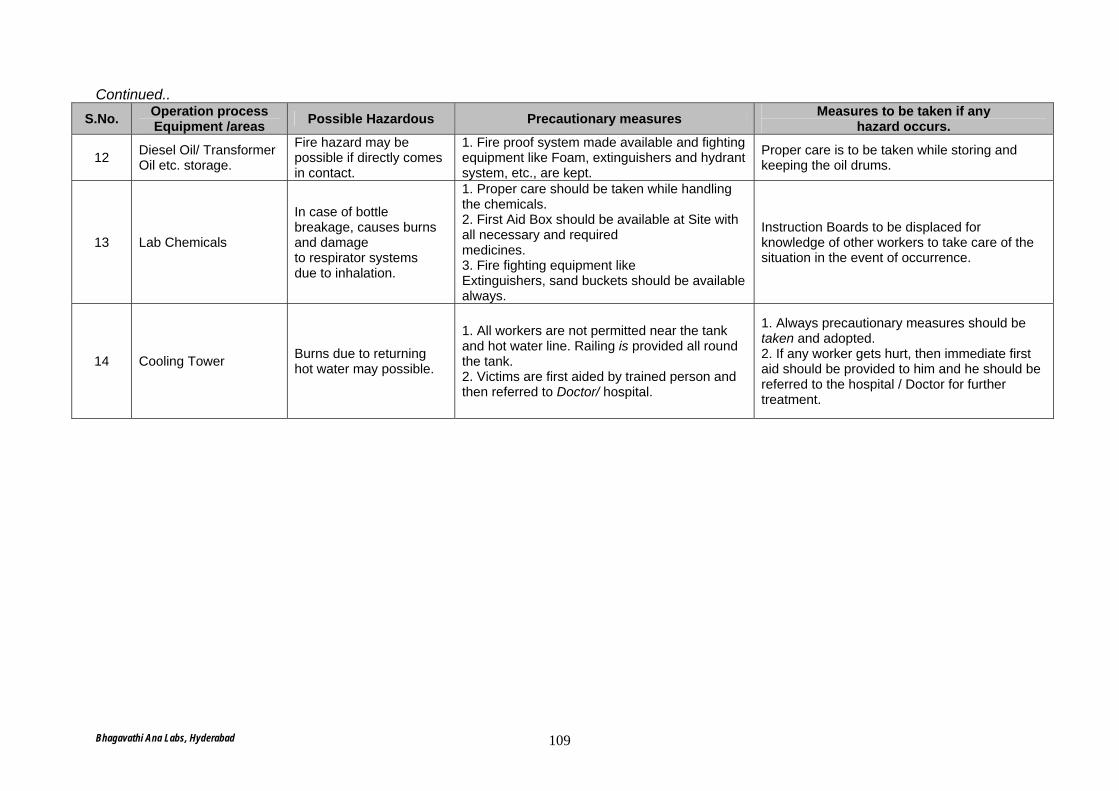
Continued.. S.No. Operation process
Equipment /areas Possible Hazardous Precautionary measures Measures to be taken if any hazard occurs.
12 Diesel Oil/ Transformer Oil etc. storage.
Fire hazard may be possible if directly comes in contact.
1. Fire proof system made available and fighting equipment like Foam, extinguishers and hydrant system, etc., are kept.
Proper care is to be taken while storing and keeping the oil drums.
13 Lab Chemicals
In case of bottle breakage, causes burns and damage to respirator systems due to inhalation.
1. Proper care should be taken while handling the chemicals. 2. First Aid Box should be available at Site with all necessary and required medicines. 3. Fire fighting equipment like Extinguishers, sand buckets should be available always.
Instruction Boards to be displaced for knowledge of other workers to take care of the situation in the event of occurrence.
14 Cooling Tower Burns due to returning hot water may possible.
1. All workers are not permitted near the tank and hot water line. Railing is provided all round the tank. 2. Victims are first aided by trained person and then referred to Doctor/ hospital.
1. Always precautionary measures should be taken and adopted. 2. If any worker gets hurt, then immediate first aid should be provided to him and he should be referred to the hospital / Doctor for further treatment.
Bhagavathi Ana Labs, Hyderabad 109
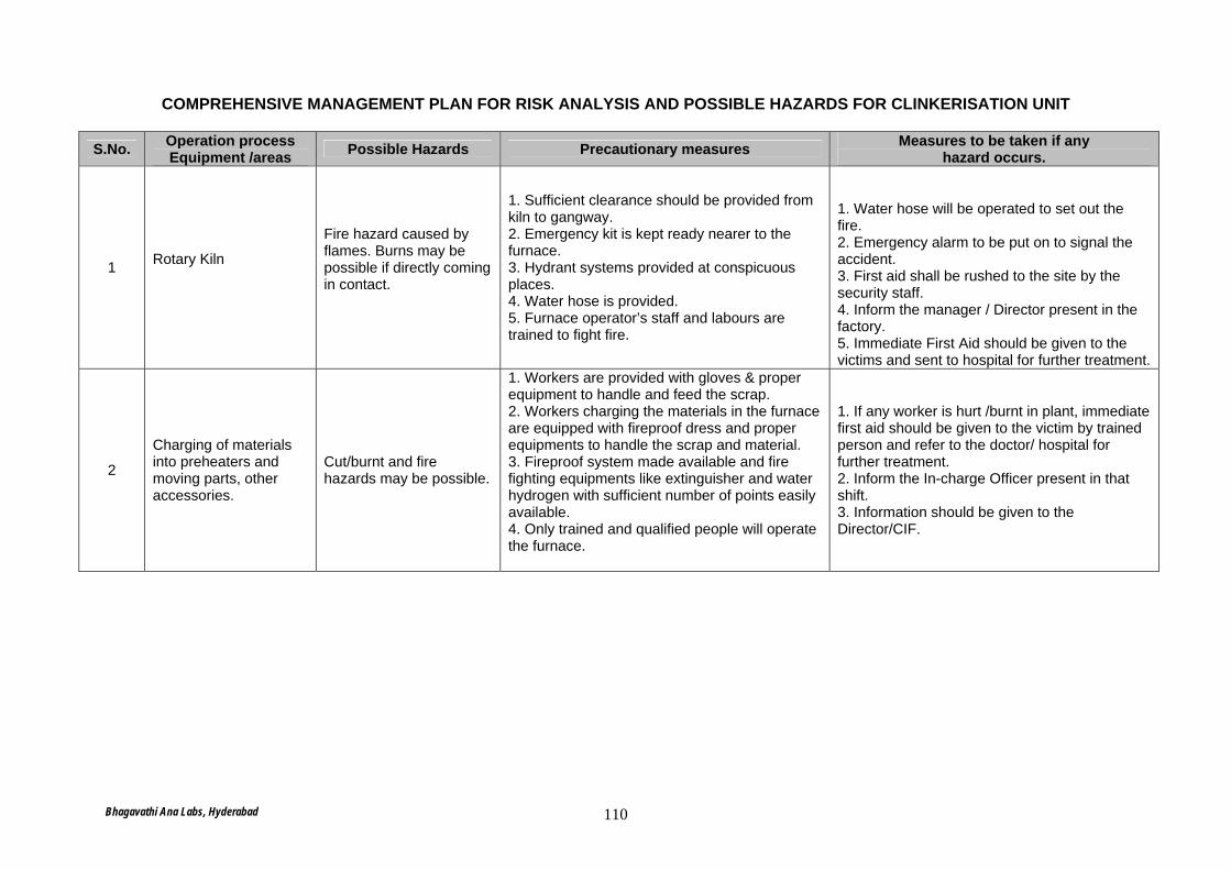
COMPREHENSIVE MANAGEMENT PLAN FOR RISK ANALYSIS AND POSSIBLE HAZARDS FOR CLINKERISATION UNIT
S.No. Operation process Equipment /areas Possible Hazards Precautionary measures Measures to be taken if any
hazard occurs.
1 Rotary Kiln
Fire hazard caused by flames. Burns may be possible if directly coming in contact.
1. Sufficient clearance should be provided from kiln to gangway. 2. Emergency kit is kept ready nearer to the furnace. 3. Hydrant systems provided at conspicuous places. 4. Water hose is provided. 5. Furnace operator’s staff and labours are trained to fight fire.
1. Water hose will be operated to set out the fire. 2. Emergency alarm to be put on to signal the accident. 3. First aid shall be rushed to the site by the security staff. 4. Inform the manager / Director present in the factory. 5. Immediate First Aid should be given to the victims and sent to hospital for further treatment.
2
Charging of materials into preheaters and moving parts, other accessories.
Cut/burnt and fire hazards may be possible.
1. Workers are provided with gloves & proper equipment to handle and feed the scrap. 2. Workers charging the materials in the furnace are equipped with fireproof dress and proper equipments to handle the scrap and material. 3. Fireproof system made available and fire fighting equipments like extinguisher and water hydrogen with sufficient number of points easily available. 4. Only trained and qualified people will operate the furnace.
1. If any worker is hurt /burnt in plant, immediate first aid should be given to the victim by trained person and refer to the doctor/ hospital for further treatment. 2. Inform the In-charge Officer present in that shift. 3. Information should be given to the Director/CIF.
Bhagavathi Ana Labs, Hyderabad 110
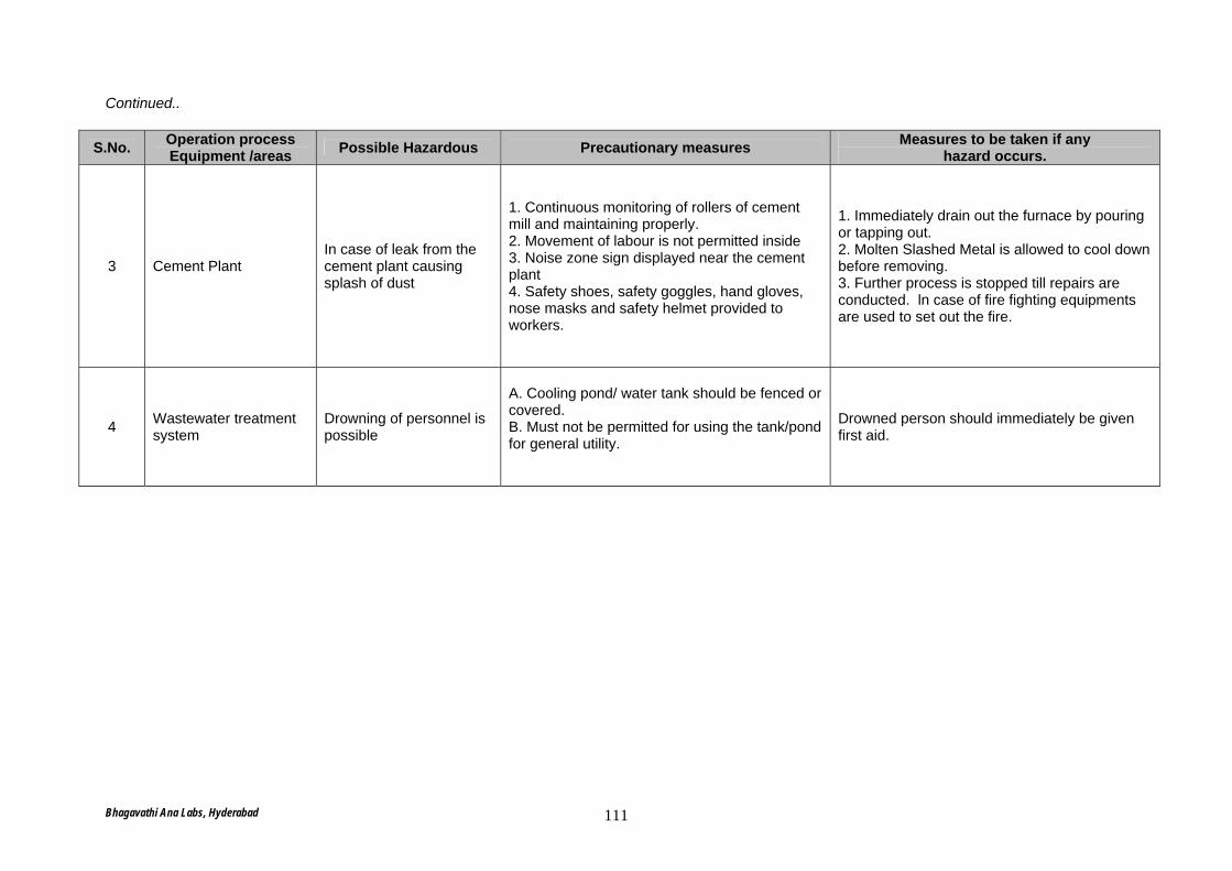
Continued..
S.No. Operation process Equipment /areas Possible Hazardous Precautionary measures Measures to be taken if any
hazard occurs.
3 Cement Plant In case of leak from the cement plant causing splash of dust
1. Continuous monitoring of rollers of cement mill and maintaining properly. 2. Movement of labour is not permitted inside 3. Noise zone sign displayed near the cement plant 4. Safety shoes, safety goggles, hand gloves, nose masks and safety helmet provided to workers.
1. Immediately drain out the furnace by pouring or tapping out. 2. Molten Slashed Metal is allowed to cool down before removing. 3. Further process is stopped till repairs are conducted. ln case of fire fighting equipments are used to set out the fire.
4 Wastewater treatment system
Drowning of personnel is possible
A. Cooling pond/ water tank should be fenced or covered. B. Must not be permitted for using the tank/pond for general utility.
Drowned person should immediately be given first aid.
Bhagavathi Ana Labs, Hyderabad 111
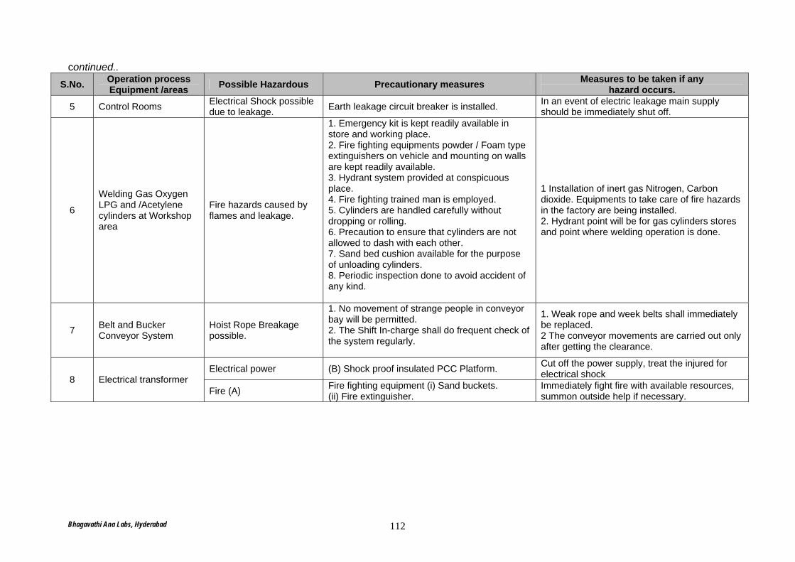
continued.. S.No. Operation process
Equipment /areas Possible Hazardous Precautionary measures Measures to be taken if any hazard occurs.
5 Control Rooms Electrical Shock possible due to leakage. Earth leakage circuit breaker is installed. In an event of electric leakage main supply
should be immediately shut off.
6
Welding Gas Oxygen LPG and /Acetylene cylinders at Workshop area
Fire hazards caused by flames and leakage.
1. Emergency kit is kept readily available in store and working place. 2. Fire fighting equipments powder / Foam type extinguishers on vehicle and mounting on walls are kept readily available. 3. Hydrant system provided at conspicuous place. 4. Fire fighting trained man is employed. 5. Cylinders are handled carefully without dropping or rolling. 6. Precaution to ensure that cylinders are not allowed to dash with each other. 7. Sand bed cushion available for the purpose of unloading cylinders. 8. Periodic inspection done to avoid accident of any kind.
1 Installation of inert gas Nitrogen, Carbon dioxide. Equipments to take care of fire hazards in the factory are being installed. 2. Hydrant point will be for gas cylinders stores and point where welding operation is done.
7 Belt and Bucker Conveyor System
Hoist Rope Breakage possible.
1. No movement of strange people in conveyor bay will be permitted. 2. The Shift In-charge shall do frequent check of the system regularly.
1. Weak rope and week belts shall immediately be replaced. 2 The conveyor movements are carried out only after getting the clearance.
Electrical power (B) Shock proof insulated PCC Platform. Cut off the power supply, treat the injured for electrical shock 8 Electrical transformer
Fire (A) Fire fighting equipment (i) Sand buckets. (ii) Fire extinguisher.
Immediately fight fire with available resources, summon outside help if necessary.
Bhagavathi Ana Labs, Hyderabad 112
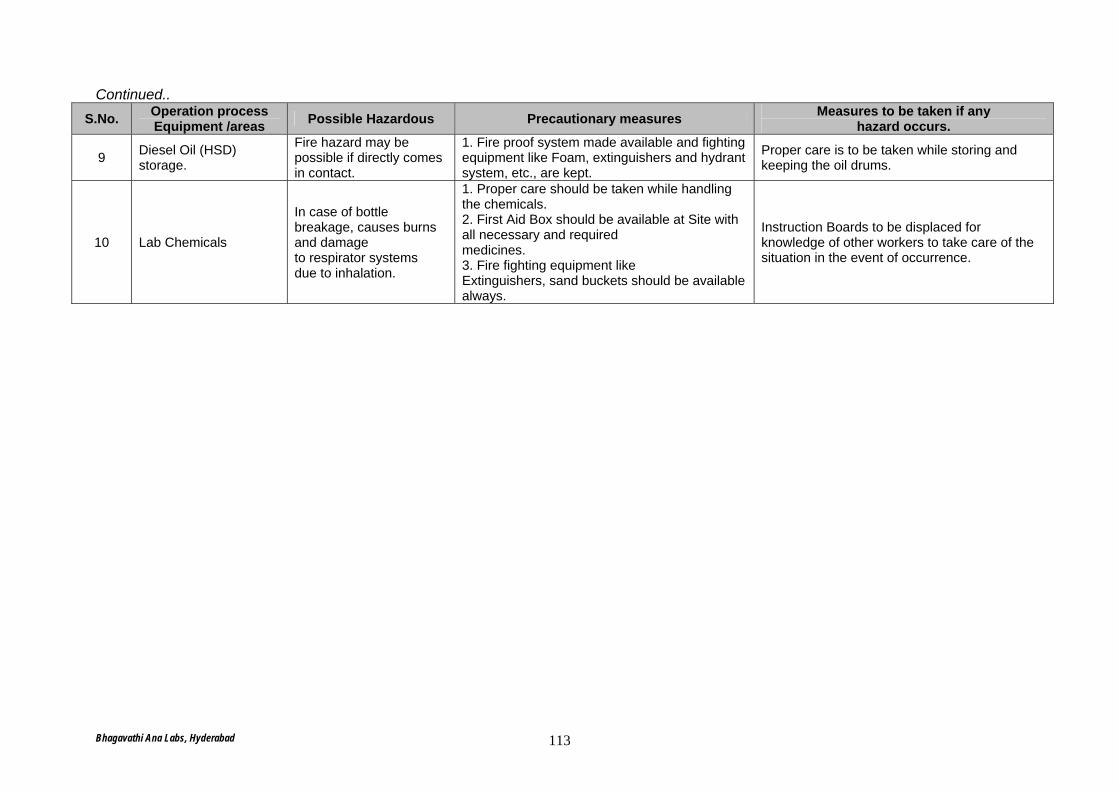
Continued.. S.No. Operation process
Equipment /areas Possible Hazardous Precautionary measures Measures to be taken if any hazard occurs.
9 Diesel Oil (HSD) storage.
Fire hazard may be possible if directly comes in contact.
1. Fire proof system made available and fighting equipment like Foam, extinguishers and hydrant system, etc., are kept.
Proper care is to be taken while storing and keeping the oil drums.
10 Lab Chemicals
In case of bottle breakage, causes burns and damage to respirator systems due to inhalation.
1. Proper care should be taken while handling the chemicals. 2. First Aid Box should be available at Site with all necessary and required medicines. 3. Fire fighting equipment like Extinguishers, sand buckets should be available always.
Instruction Boards to be displaced for knowledge of other workers to take care of the situation in the event of occurrence.
Bhagavathi Ana Labs, Hyderabad 113
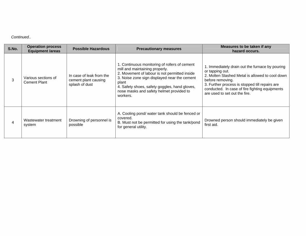
Continued..
S.No. Operation process Equipment /areas Possible Hazardous Precautionary measures Measures to be taken if any
hazard occurs.
3 Various sections of Cement Plant
In case of leak from the cement plant causing splash of dust
1. Continuous monitoring of rollers of cement mill and maintaining properly. 2. Movement of labour is not permitted inside 3. Noise zone sign displayed near the cement plant 4. Safety shoes, safety goggles, hand gloves, nose masks and safety helmet provided to workers.
1. Immediately drain out the furnace by pouring or tapping out. 2. Molten Slashed Metal is allowed to cool down before removing. 3. Further process is stopped till repairs are conducted. ln case of fire fighting equipments are used to set out the fire.
4 Wastewater treatment system
Drowning of personnel is possible
A. Cooling pond/ water tank should be fenced or covered. B. Must not be permitted for using the tank/pond for general utility.
Drowned person should immediately be given first aid.
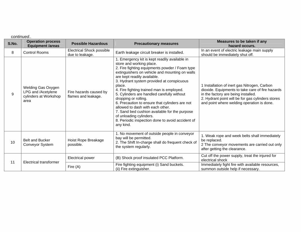
continued.. S.No. Operation process
Equipment /areas Possible Hazardous Precautionary measures Measures to be taken if any hazard occurs.
8 Control Rooms Electrical Shock possible due to leakage. Earth leakage circuit breaker is installed. In an event of electric leakage main supply
should be immediately shut off.
9
Welding Gas Oxygen LPG and /Acetylene cylinders at Workshop area
Fire hazards caused by flames and leakage.
1. Emergency kit is kept readily available in store and working place. 2. Fire fighting equipments powder / Foam type extinguishers on vehicle and mounting on walls are kept readily available. 3. Hydrant system provided at conspicuous place. 4. Fire fighting trained man is employed. 5. Cylinders are handled carefully without dropping or rolling. 6. Precaution to ensure that cylinders are not allowed to dash with each other. 7. Sand bed cushion available for the purpose of unloading cylinders. 8. Periodic inspection done to avoid accident of any kind.
1 Installation of inert gas Nitrogen, Carbon dioxide. Equipments to take care of fire hazards in the factory are being installed. 2. Hydrant point will be for gas cylinders stores and point where welding operation is done.
10 Belt and Bucker Conveyor System
Hoist Rope Breakage possible.
1. No movement of outside people in conveyor bay will be permitted. 2. The Shift In-charge shall do frequent check of the system regularly.
1. Weak rope and week belts shall immediately be replaced. 2 The conveyor movements are carried out only after getting the clearance.
Electrical power (B) Shock proof insulated PCC Platform. Cut off the power supply, treat the injured for electrical shock 11 Electrical transformer
Fire (A) Fire fighting equipment (i) Sand buckets. (ii) Fire extinguisher.
Immediately fight fire with available resources, summon outside help if necessary.
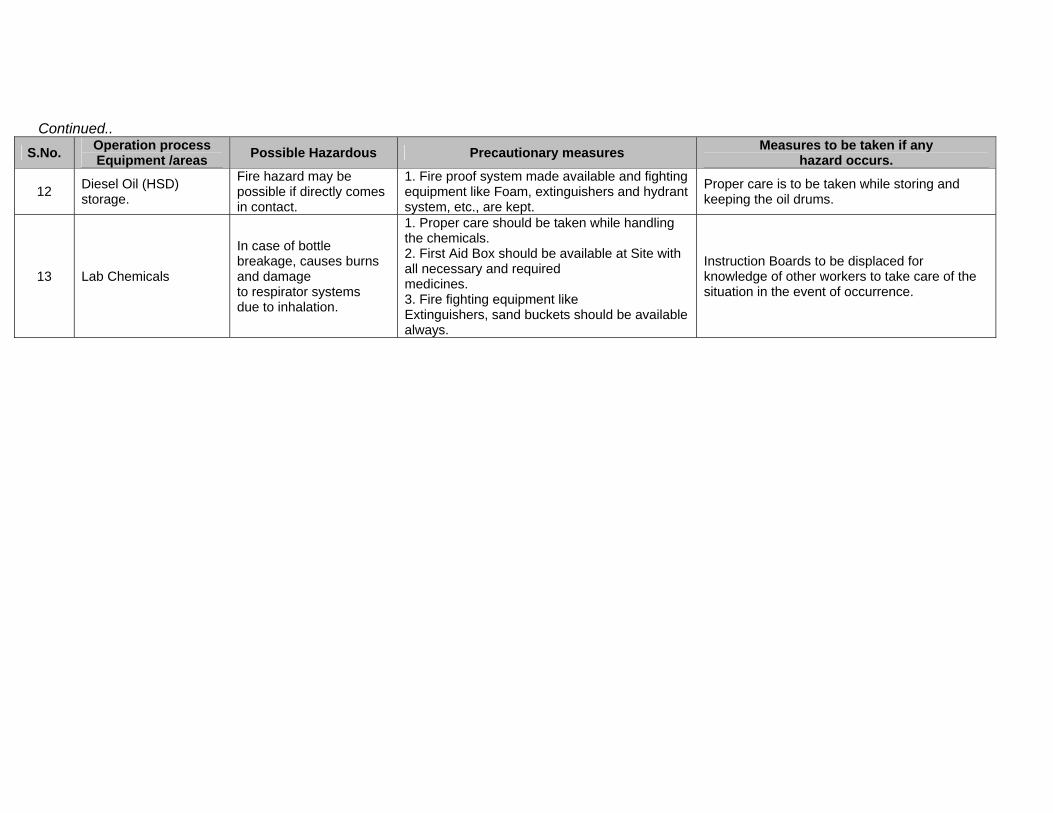
Continued.. S.No. Operation process
Equipment /areas Possible Hazardous Precautionary measures Measures to be taken if any hazard occurs.
12 Diesel Oil (HSD) storage.
Fire hazard may be possible if directly comes in contact.
1. Fire proof system made available and fighting equipment like Foam, extinguishers and hydrant system, etc., are kept.
Proper care is to be taken while storing and keeping the oil drums.
13 Lab Chemicals
In case of bottle breakage, causes burns and damage to respirator systems due to inhalation.
1. Proper care should be taken while handling the chemicals. 2. First Aid Box should be available at Site with all necessary and required medicines. 3. Fire fighting equipment like Extinguishers, sand buckets should be available always.
Instruction Boards to be displaced for knowledge of other workers to take care of the situation in the event of occurrence.