Embed Size (px)
Citation preview
STANG et al.: MEDUSA: A SCALABLE MR CONSOLE USING USB 1
Medusa:A Scalable MR Console Using USB
Pascal P. Stang, Steven M. Conolly, Juan M. Santos, John M. Pauly, Greig C. Scott
Abstract—MRI pulse sequence consoles typically employ closedproprietary hardware, software, and interfaces, making difficultany adaptation for innovative experimental technology. Yet MRIsystems research is trending to higher channel count receivers,transmitters, gradient/shims, and unique interfaces for interven-tional applications. Customized console designs are now feasiblefor researchers with modern electronic components, but high datarates, synchronization, scalability, and cost present importantchallenges. Implementing large multi-channel MR systems withefficiency and flexibility requires a scalable modular architecture.With Medusa, we propose an open system architecture usingthe Universal Serial Bus (USB) for scalability, combined withdistributed processing and buffering to address the high datarates and strict synchronization required by multi-channel MRI.Medusa uses a modular design concept based on digital syn-thesizer, receiver, and gradient blocks, in conjunction with fastprogrammable logic for sampling and synchronization. Medusais a form of synthetic instrument, being reconfigurable for avariety of medical/scientific instrumentation needs. The Medusadistributed architecture, scalability, and data bandwidth limitsare presented, and its flexibility is demonstrated in a variety ofnovel MRI applications.
Index Terms—Medusa, magnetic resonance imaging (MRI),Universal Serial Bus (USB), direct digital synthesizer, digitalreceiver, radio-frequency instrumentation, console, synthetic in-strumentation.
I. INTRODUCTION
MAGNETIC Resonance Imaging, through its ability tomanipulate nuclear spin magnetization, provides excep-
tional versatility to image anatomy and physiological function.MRI pulse sequences require real-time control of RF and gra-dient systems, data acquisition, and processing, all coordinatedby an intelligent console. Historically, MRI console design hasbeen the domain of major systems manufacturers, command-ing significant engineering time and financial resources. Thesesystems, targeted towards major medical and research markets,are typically closed with proprietary hardware, software, andinterfaces, making difficult any expansion or adaptation to
P. P. Stang is with the Magnetic Resonance Systems Research Laboratory,Department of Electrical Engineering, Stanford University, Stanford, CA,94305 USA e-mail: [email protected]
S. M. Conolly is with the Department of Bioengineering, University ofCalifornia, Berkeley, CA, 94720 USA and with the Magnetic ResonanceSystems Research Laboratory, Department of Electrical Engineering, StanfordUniversity, Stanford, CA, 94305 USA
J. M. Santos is with HeartVista, Inc., 715 Colorado Ave - Suite D, PaloAlto, CA 94306 USA
J. M. Pauly and G. C. Scott are with the Magnetic Resonance Systems Re-search Laboratory, Department of Electrical Engineering, Stanford University,Stanford, CA, 94305 USA
Copyright c©2011 IEEE. Personal use of this material is permitted. How-ever, permission to use this material for any other purposes must be obtainedfrom the IEEE by sending a request to [email protected].
new techniques and experiments. FDA regulations on thedesign process, vendor marketing decisions, and reimburse-ment issues create political disincentives to rapid develop-ment. A confluence of these factors hinders innovations ininterventional MRI, MR-guided therapies, and inhibits MRengineering education.
However, with advances in computer infrastructure, anddigital and analog RF integrated circuits, investigators cannow devise custom console designs targeted to their researchneeds [1]–[5]. Even so, MRI research systems are trendingtowards high channel-count receivers [6], [7], transmitterarrays [8], field cameras [9], [10] and even gradient/shimarrays [11], [12]. Meeting modern expectations for highchannel counts, customized interfaces and real-time imagingperformance poses a considerable design challenge. As oneexample, direct RF sampling/synthesis with modern wide-bandanalog-to-digital (ADC) and digital-to-analog (DAC) convert-ers permit typically analog RF operations such as mixing,channel filtering, and modulation to be performed in the digitaldomain, a concept generally known as software defined radio(SDR) [13], [14]. While this has made the RF portion of MRIeasier to realize, SDR approaches place additional pressure onthe systems which must handle the new large flows of digitaldata. Implementing such systems with efficiency and flexibilityrequires a scalable modular system architecture.
Standard multi-core PC’s can now handle user interfaceand image reconstruction duties in real-time [21], yet efficientdata handling and real-time control remains a problem. Tightlyintegrated console hardware, such as PCI cards, provide high-throughput low-latency communication, but sacrifice scalabil-ity, cost effectiveness, and design time. Moreover, the PCthen becomes directly involved with low-level MRI systemoperation - an untenable compromise given typical operatingsystem stability and security. The handling of hard real timetasks with PC (or microcontroller) software may provide highflexibility, but imposes harsh restrictions on software designand inefficient use of available processing power and hardwareresources. For example, one may expend considerable codingeffort and even CPU time to ensure that a controller issimply ready to perform real-time operations. Bus technologieslike USB or Ethernet are intrinsically scalable, but place thePC at arms length from system hardware, forcing real-timesampling and pulse sequence tasks to be handled by thelocal console hardware. Data must be buffered locally, thenefficiently communicated to the PC with low latency.
At the 2005 ISMRM [15], we proposed a USB approachto MRI system design that could address these requirements(Fig. 1). This has now evolved into a full synthetic instrument
STANG et al.: MEDUSA: A SCALABLE MR CONSOLE USING USB 2
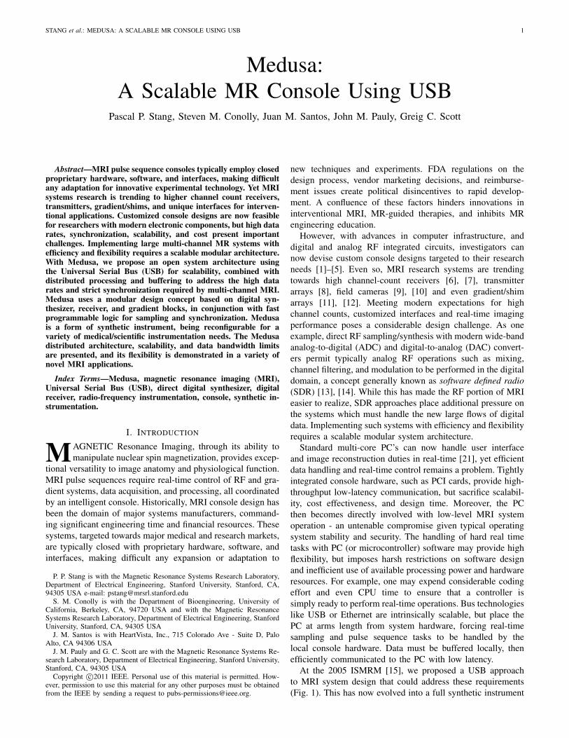
Fig. 1. The first proof-of-concept Medusa console hardware with (a)prototype RF transciever module, (b) prototype gradient control module, and(c) a USB hub with multiple transaction translators.
prototype termed Medusa. Synthetic instrumentation refers tothe use of reconfigurable building blocks to construct advancedinstrumentation, while the name Medusa stems from the sys-tem’s ever-expanding cables resembling a jellyfish or the headof the character from Greek mythology. In our design concept,we have investigated a highly scalable MR system based ondigital synthesizer, digital receiver, and gradient blocks oper-ating as a network of Universal Serial Bus peripherals. The ef-ficacy of this approach will depend upon efficient architectureand design: distributed processing, efficient use of hardware,streamlined efficient data flow, and leveraging of commoditycommunication buses and components. Here, we present thearchitectural details of Medusa, its bandwidth and scalabilitylimits using distributed USB data transport, its performancemetrics for software-defined all-digital RF transmission andreception for parallel scalable MRI systems. Finally, variousconfigurations are demonstrated, and its suitability for othernovel instrumentation applications are discussed.
II. METHODS
A. System Design Philosophy
The Medusa console aims to deliver the complete setof basic MRI console functions including multi-channel RFexcitation and reception, gradient waveform generation, RFcoil and amplifier gating, and an open software platformfor console control, pulse sequencing, and experimentation.Furthermore, we target a modular architecture for scalability,and a performance level sufficient to enable modern fastimaging with RF and gradient bandwidths of at least 250Ksamples per second per channel, support for 100% dutycycle operation, and at least 16 bits of RF receiver dynamicrange. To satisfy these requirements, hardware developmentwas guided by three dominant priorities: use ”digital” RFcomponents to simplify and streamline the RF subsystems,employ a modular architecture with distributed processing forflexible system configuration and scalability to high channelcounts, and leverage commodity PC peripheral interfaces forscalability, fast data transfer, interoperability, cost-efficiency,and a modicum of protection against hardware obsolescence.We chose Universal Serial Bus (USB) as our data transportfor its support of up to 127 devices per bus, guaranteed data
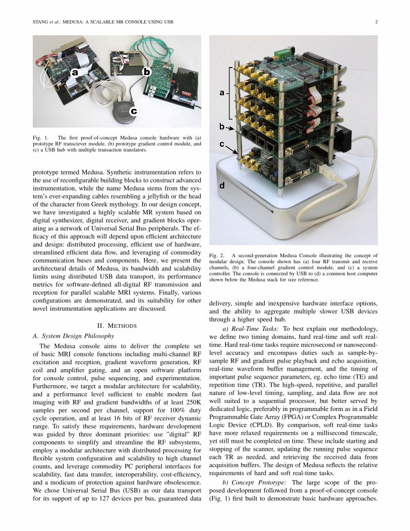
Fig. 2. A second-generation Medusa Console illustrating the concept ofmodular design. The console shown has (a) four RF transmit and receivechannels, (b) a four-channel gradient control module, and (c) a systemcontroller. The console is connected by USB to (d) a common host computershown below the Medusa stack for size reference.
delivery, simple and inexpensive hardware interface options,and the ability to aggregate multiple slower USB devicesthrough a higher speed hub.
a) Real-Time Tasks: To best explain our methodology,we define two timing domains, hard real-time and soft real-time. Hard real-time tasks require microsecond or nanosecond-level accuracy and encompass duties such as sample-by-sample RF and gradient pulse playback and echo acquisition,real-time waveform buffer management, and the timing ofimportant pulse sequence parameters, eg. echo time (TE) andrepetition time (TR). The high-speed, repetitive, and parallelnature of low-level timing, sampling, and data flow are notwell suited to a sequential processor, but better served bydedicated logic, preferably in programmable form as in a FieldProgrammable Gate Array (FPGA) or Complex ProgrammableLogic Device (CPLD). By comparison, soft real-time taskshave more relaxed requirements on a millisecond timescale,yet still must be completed on time. These include starting andstopping of the scanner, updating the running pulse sequenceeach TR as needed, and retrieving the received data fromacquisition buffers. The design of Medusa reflects the relativerequirements of hard and soft real-time tasks.
b) Concept Prototype: The large scope of the pro-posed development followed from a proof-of-concept console(Fig. 1) first built to demonstrate basic hardware approaches.
STANG et al.: MEDUSA: A SCALABLE MR CONSOLE USING USB 3
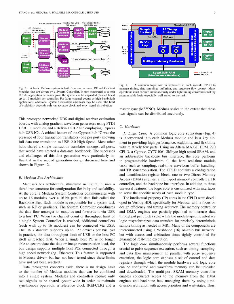
Fig. 3. A basic Medusa system is built from one or more RF and GradientModules that are driven by a System Controller, in turn connected to a hostPC. As application demands grow, the system can be expanded (dashed lines)up to 16 modules per controller. For large channel counts or high-bandwidthapplications, additional System Controllers and hosts may be used. The limitof scalability depends only on accurate clock and sync signal distrubution.
This prototype networked DDS and digital receiver evaluationboards, with analog gradient waveform generators using FTDIUSB 1.1 modules, and a Belkin USB 2 hub employing Cypresshub USB ICs. A critical feature of the Cypress hub IC was thepresence of four transaction translators (one per port) allowingfull data rate translation to USB 2.0 High-Speed. Most otherhubs shared a single transaction translator amongst all ports,that would have created a data-rate bottleneck. The successesand challenges of this first generation were particularly in-fluential in the second generation design discussed here andshown in Figure 2.
B. Medusa Bus Architecture
Medusa’s bus architecture, illustrated in Figure 3, uses atiered tree structure for configuration flexibilty and scalability.At the core, a Medusa System Controller communicates withup to 16 modules over a 16-bit parallel data link called theBackbone Bus. Each module is responsible for a system tasksuch as RF or gradients. The System Controller coordinatesthe data flow amongst its modules and forwards it via USBto a host PC. When the channel count or throughput limit ofa single System Controller is reached, additional controllers(each with up to 16 modules) can be connected via USB.The USB standard supports up to 127 devices per bus, yetin practice, the data throughput limit of USB or the host PCitself is reached first. When a single host PC is no longerable to accomodate the data or image reconstruction load, thebus design supports multiple host PCs connected through ahigh speed network (eg. Ethernet). This feature is supportedin Medusa drivers but has not been tested since these limitshave not yet been reached.
Data throughput concerns aside, there is no design limitto the number of Medusa modules that can be combinedinto a single system. Modules and controllers require onlytwo signals to be shared system-wide in order to maintainsynchronous operation: a reference clock (REFCLK) and a
Fig. 4. A common logic core is replicated in each module CPLD tomanage timing, data sampling, buffering, and sequence flow control. Manyoperations must execute simultaneously under tight timing constraints makingprogammable logic especially well suited to the task.
master sync (MSYNC). Medusa scales to the extent that thesetwo signals can be distributed accurately.
C. Hardware
1) Logic Core: A common logic core subsystem (Fig. 4)is incorporated into each Medusa module and is a key ele-ment in providing high performance, scalability, and flexibilitywith relatively few parts. Using an Altera MAX-II EPM1270CPLD, a Cypress CY7C1061 2Mbyte high-speed SRAM, andan addressable backbone bus interface, the core performsin programmable hardware all the hard real-time moduletasks such as sampling, real-time waveform buffer handling,and TR synchronization. The CPLD contains a configurationand identification register block, one or two Direct MemoryAccess (DMA) engines, a multi-port memory controller, a TRcontroller, and the backbone bus interface. In addition to theseuniversal features, the logic core is customized with interfacesto serve the specific needs of each module type.
The intellectual-property (IP) cores in the CPLD were devel-oped in Verilog HDL specifically for Medusa, with a focus ondesign efficiency and timing accuracy. The memory controllerand DMA engines are partially-pipelined to increase datathroughput per clock cycle, while the module-specific interfacelogic resynchronizes data transfers for precisely deterministicsample timing as needed in MRI. Many of the components areinterconnected using a Wishbone [16] on-chip bus network,but with access and arbitration times tightly controlled forguaranteed real-time execution.
The logic core simultaneously performs several functionscrucial to pulse sequence execution, such as timing, sampling,and data flow management. In parallel with pulse sequenceexecution, the logic core exposes a set of control and dataregisters through which the module hardware and logic corecan be configured and waveform memory can be uploadedand downloaded. The multi-port SRAM memory controllerenables concurrent access to the memory from the DMAengines and backbone bus, managing them by using time-division arbitration with access priorities and wait-states. Thus,
STANG et al.: MEDUSA: A SCALABLE MR CONSOLE USING USB 4
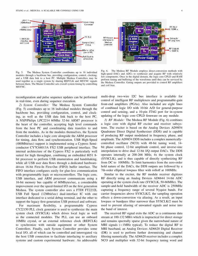
Fig. 5. The Medusa System Controller coordinates up to 16 individualmodules through a backbone bus, providing configuration, control, clocking,and a USB data link to a host PC. Multiple Medusa Controllers may beused together as a single system by sharing REFCLK and MSYNC signalsbetween them. The Master Controller sets overall system timing by controllingMSYNC.
reconfiguration and pulse sequence updates can be performedin real-time, even during sequence execution.
2) System Controller: The Medusa System Controller(Fig. 5) coordinates up to 16 individual modules through thebackbone bus, providing configuration, control, and clock-ing, as well as the USB data link back to the host PC.A NXP/Philips LPC2214 60Mhz 32-bit ARM7 processor isthe heart of the controller, accepting high level commandsfrom the host PC and coordinating data transfers to andfrom the modules. As in the modules themselves, the SystemController includes a logic core alongside the ARM processorfor timing, data flow, and synchronization. USB High-Speed(480Mbit/sec) support is implemented using a Cypress Semi-conductor CY7C68013A FX2 USB peripheral interface. Theinternal architecture of the Cypress FX2 is particularly wellsuited for high throughput, combining an embedded 8051 8-bit processor to perform USB enumeration and handshaking,while all USB user data flows through a dedicated hardware-driven 16-bit First-In First-Out (FIFO) buffer interface. TheFIFO interface configures easily for glue-less communicationwith programmable logic or microcontrollers. The logic core,USB interface, and ARM processor communicate using a16-bit memory bus capable of 60Mbytes/sec, a considerableimprovement over the speed-limited I/O on the first generationMedusa. The system controller also uses a FTDI FT2232LUSB Full Speed (12Mbit/sec) dual-interface IC with oneinterface dedicated to a serial debug terminal, and the other tosupport the legacy first-generation USB protocol and software.
For maximum flexibility, a programmable CypressCY22150 PLL clock generator is used to synthesize the mainsystem clock (SYSCLK) which drives local logic as wellas the connected modules. The PLL can use an onboard10MHz crystal, or an external reference clock (REFCLK)to synchronize with outside equipment or other SystemControllers. Finally, each System Controller provides somelocal I/O, all of which can be controlled and interrogated viathe host USB connection to facilitate interfacing to auxiliarysystems and custom experimental hardware. An addressable
Fig. 6. The Medusa RF Module employs direct-conversion methods withhigh-speed DACs and ADCs to synthesize and acquire RF with relativelyfew components. Once in the digital domain, the logic core CPLD and RAMperform timing and buffering of the waveforms until they can be serviced bythe Medusa Controller. Gating outputs are provided to control RF amplifiersand coil bias.
multi-drop two-wire I2C bus interface is available forcontrol of intelligent RF multiplexers and programmable-gainfront-end amplifiers (PGAs). Also included are eight linesof combined logic I/O with 10-bit A/D for general-purposecontrol and sensing, and a 10-pin JTAG port for in-systemupdating of the logic core CPLD firmware on any module.
3) RF Module: The Medusa RF Module (Fig. 6) combinesa logic core with digital RF exciter and receiver subsys-tems. The exciter is based on the Analog Devices AD9854Quadrature Direct Digital Synthesizer (DDS) and is capableof producing RF output modulated in frequency, phase, andamplitude. The AD9854 DDS includes a complex numerically-controlled oscillator (NCO) with 48-bit tuning word, 14-bit phase control, 12-bit amplitude control, and inverse-sincinterpolation to drive dual 12-bit I/Q output DACs. The DDSoperates internally at 200-266 MHz, 4x the system clock(SYSCLK), and is thus capable of directly synthesizing RFfrom DC to 100MHz. To limit harmonics from the zero-orderhold nature of the DACs, the DDS outputs are followed by a7th-order elliptical lowpass filter with rolloff at 100MHz.
Similar to the exciter, the RF module receiver digitizesRF directly using an Analog Devices AD6644 14-bit ADCoperating at the system clock rate (SYSCLK, 50-66MHz). Thesample-and-hold bandwidth of the receiver ADC is 250MHzcapturing a frequency range of several Nyquist bands. Forcarrier frequencies above SYSCLK/2, the sampling operationeffects a down-conversion via aliasing. As a result, an inputlowpass or bandpass filter narrower than SYSCLK/2 must beused to prevent aliasing of unwanted signals and noise intothe band of interest.
The received RF signal exits the ADC as a continuous datastream at 100-132 MB/s which is impractical for direct storageand remains spectrally sparse given the narrowband nature ofMRI signals (<1MHz typical). To reduce the digital RF toMRI baseband, an Analog Devices AD6620 Digital Receiver(DR) is used to perform further downmixing and channelfiltering numerically. The AD6620 receiver includes a complexNCO and multiplier with 32-bit frequency tuning word and
STANG et al.: MEDUSA: A SCALABLE MR CONSOLE USING USB 5
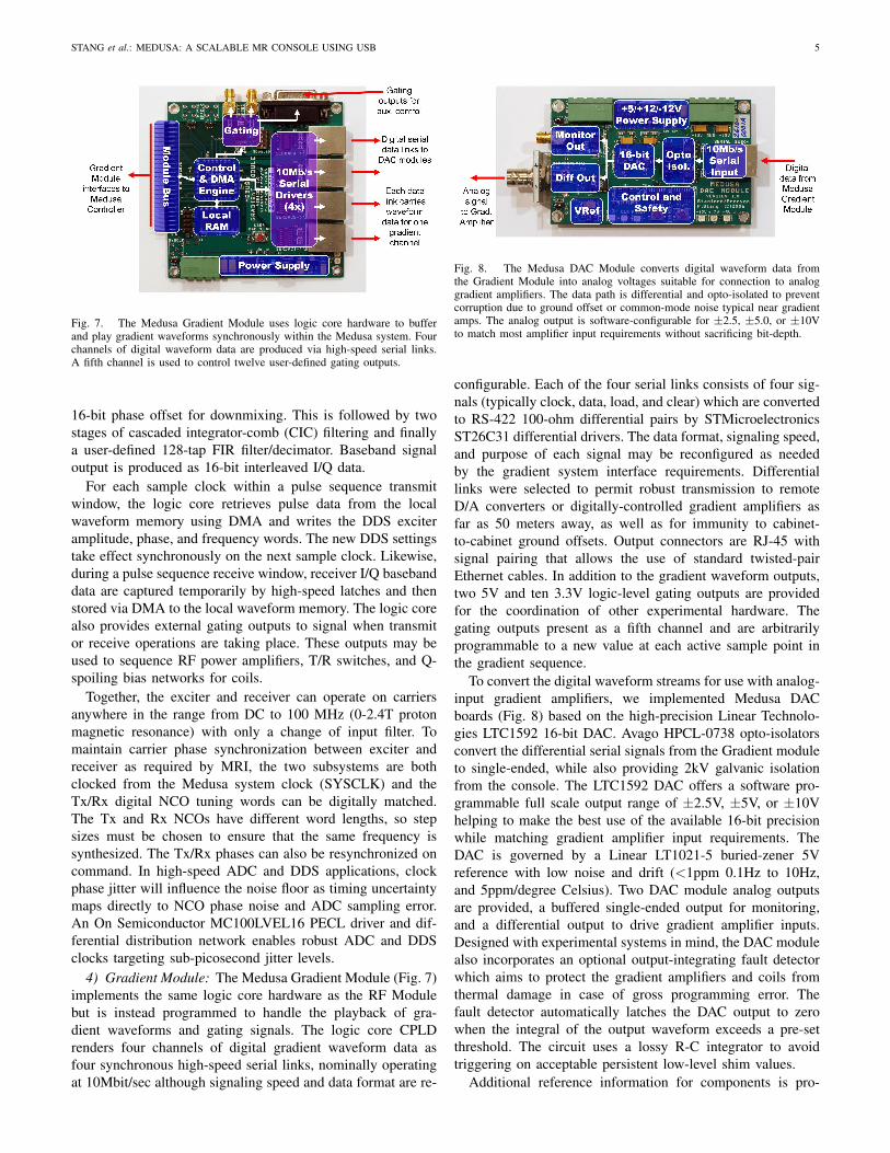
Fig. 7. The Medusa Gradient Module uses logic core hardware to bufferand play gradient waveforms synchronously within the Medusa system. Fourchannels of digital waveform data are produced via high-speed serial links.A fifth channel is used to control twelve user-defined gating outputs.
16-bit phase offset for downmixing. This is followed by twostages of cascaded integrator-comb (CIC) filtering and finallya user-defined 128-tap FIR filter/decimator. Baseband signaloutput is produced as 16-bit interleaved I/Q data.
For each sample clock within a pulse sequence transmitwindow, the logic core retrieves pulse data from the localwaveform memory using DMA and writes the DDS exciteramplitude, phase, and frequency words. The new DDS settingstake effect synchronously on the next sample clock. Likewise,during a pulse sequence receive window, receiver I/Q basebanddata are captured temporarily by high-speed latches and thenstored via DMA to the local waveform memory. The logic corealso provides external gating outputs to signal when transmitor receive operations are taking place. These outputs may beused to sequence RF power amplifiers, T/R switches, and Q-spoiling bias networks for coils.
Together, the exciter and receiver can operate on carriersanywhere in the range from DC to 100 MHz (0-2.4T protonmagnetic resonance) with only a change of input filter. Tomaintain carrier phase synchronization between exciter andreceiver as required by MRI, the two subsystems are bothclocked from the Medusa system clock (SYSCLK) and theTx/Rx digital NCO tuning words can be digitally matched.The Tx and Rx NCOs have different word lengths, so stepsizes must be chosen to ensure that the same frequency issynthesized. The Tx/Rx phases can also be resynchronized oncommand. In high-speed ADC and DDS applications, clockphase jitter will influence the noise floor as timing uncertaintymaps directly to NCO phase noise and ADC sampling error.An On Semiconductor MC100LVEL16 PECL driver and dif-ferential distribution network enables robust ADC and DDSclocks targeting sub-picosecond jitter levels.
4) Gradient Module: The Medusa Gradient Module (Fig. 7)implements the same logic core hardware as the RF Modulebut is instead programmed to handle the playback of gra-dient waveforms and gating signals. The logic core CPLDrenders four channels of digital gradient waveform data asfour synchronous high-speed serial links, nominally operatingat 10Mbit/sec although signaling speed and data format are re-
Fig. 8. The Medusa DAC Module converts digital waveform data fromthe Gradient Module into analog voltages suitable for connection to analoggradient amplifiers. The data path is differential and opto-isolated to preventcorruption due to ground offset or common-mode noise typical near gradientamps. The analog output is software-configurable for ±2.5, ±5.0, or ±10Vto match most amplifier input requirements without sacrificing bit-depth.
configurable. Each of the four serial links consists of four sig-nals (typically clock, data, load, and clear) which are convertedto RS-422 100-ohm differential pairs by STMicroelectronicsST26C31 differential drivers. The data format, signaling speed,and purpose of each signal may be reconfigured as neededby the gradient system interface requirements. Differentiallinks were selected to permit robust transmission to remoteD/A converters or digitally-controlled gradient amplifiers asfar as 50 meters away, as well as for immunity to cabinet-to-cabinet ground offsets. Output connectors are RJ-45 withsignal pairing that allows the use of standard twisted-pairEthernet cables. In addition to the gradient waveform outputs,two 5V and ten 3.3V logic-level gating outputs are providedfor the coordination of other experimental hardware. Thegating outputs present as a fifth channel and are arbitrarilyprogrammable to a new value at each active sample point inthe gradient sequence.
To convert the digital waveform streams for use with analog-input gradient amplifiers, we implemented Medusa DACboards (Fig. 8) based on the high-precision Linear Technolo-gies LTC1592 16-bit DAC. Avago HPCL-0738 opto-isolatorsconvert the differential serial signals from the Gradient moduleto single-ended, while also providing 2kV galvanic isolationfrom the console. The LTC1592 DAC offers a software pro-grammable full scale output range of ±2.5V, ±5V, or ±10Vhelping to make the best use of the available 16-bit precisionwhile matching gradient amplifier input requirements. TheDAC is governed by a Linear LT1021-5 buried-zener 5Vreference with low noise and drift (<1ppm 0.1Hz to 10Hz,and 5ppm/degree Celsius). Two DAC module analog outputsare provided, a buffered single-ended output for monitoring,and a differential output to drive gradient amplifier inputs.Designed with experimental systems in mind, the DAC modulealso incorporates an optional output-integrating fault detectorwhich aims to protect the gradient amplifiers and coils fromthermal damage in case of gross programming error. Thefault detector automatically latches the DAC output to zerowhen the integral of the output waveform exceeds a pre-setthreshold. The circuit uses a lossy R-C integrator to avoidtriggering on acceptable persistent low-level shim values.
Additional reference information for components is pro-
STANG et al.: MEDUSA: A SCALABLE MR CONSOLE USING USB 6
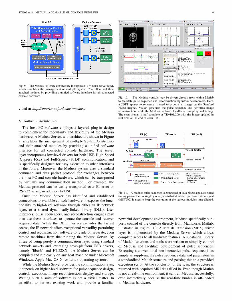
Fig. 9. The Medusa software architecture incorporates a Medusa server layer,which simplifies the management of multiple System Controllers and theirattached modules by providing a unified software interface for all connectedconsole hardware.
vided at http://mrsrl.stanford.edu/∼medusa.
D. Software Architecture
The host PC software employs a layered plug-in designto complement the modularity and flexibility of the Medusahardware. A Medusa Server, with architecture shown in Figure9, simplifies the management of multiple System Controllersand their attached modules by providing a unified softwareinterface for all connected console hardware. The serverlayer incorporates low-level drivers for both USB High-Speed(Cypress FX2) and Full-Speed (FTDI) communication, andis specifically designed for easy extension to other interfacesin the future. Moreover, the Medusa system uses a standardcommand and data packet protocol for exchanges betweenthe host PC and console hardware, which can be transportedby virtually any communication method. For example, theMedusa protocol can be easily transported over Ethernet orRS-232 serial, in addition to USB.
Once the Medusa Server has identified and establishedconnections to available console hardware, it exposes the func-tionality to high-level software through either an IP networklayer, or a shared dynamically-linked library (DLL). Userinterfaces, pulse sequencers, and reconstruction engines maythen use these interfaces to operate the console and recoveracquired data. While the DLL interface provides the fastestaccess, the IP network offers exceptional versatility permittingcontrol and reconstruction software to reside on separate, evenremote machines from that running the Medusa Server. Byvirtue of being purely a communication layer using standardnetwork sockets and leveraging cross-platform USB drivers,namely ’libusb’ and FTD2XX, the Medusa Server can becompiled and run easily on any host machine under MicrosoftWindows, Apple Mac OS X, or Linux operating systems.
While the Medusa Server provides the communication layer,it depends on higher-level software for pulse sequence design,control, execution, image reconstruction, display and storage.Writing such a suite of software is not a trivial matter. Inan effort to harness existing work and provide a familiar
Fig. 10. The Medusa console may be driven directly from within Matlabto facilitate pulse sequence and reconstruction algorithm development. Here,a 2DFT spin-echo sequence is used to acquire an image on the StanfordPMRI magnet. Matlab generates the pulse sequence and performs imagereconstruction, while the Medusa hardware handles all sampling and timing.The scan shown is half complete at TR=101/200 with the image updated inreal-time at the end of each TR.
Fig. 11. A Medusa pulse sequence is composed of data blocks and associatedtiming parameters. A single globally-distributed master synchronization signal(MSYNC) is used to keep the operation of the various modules time-aligned.
powerful development environment, Medusa specifically sup-ports control of the console directly from Mathworks Matlab,illustrated in Figure 10. A Matlab Extension (MEX) driverlayer is implemented by the Medusa Server which allowscomplete access to all hardware features. A substantial libraryof Matlab functions and tools were written to simplify controlof Medusa and facilitate development of pulse sequences.Executing a conventional non-interactive pulse sequence is assimple as supplying the pulse sequence data and parameters ina standardized Matlab structure and passing this to a providedexecution script. At the conclusion of the scan, the structure isreturned with acquired MRI data filled in. Even though Matlabis not a real-time environment, it can run Medusa successfully,even interactively, because the real-time burden is off-loadedto Medusa hardware.
STANG et al.: MEDUSA: A SCALABLE MR CONSOLE USING USB 7
E. Sequence Timing & Coordination
Pulse sequence execution typically begins with identifi-cation and configuration. The host PC software opens aconnection to the Medusa Server and requests a list of allavailable hardware, for example, the number of RF andgradient modules and channels. The pulse sequence (Fig. 11)is then defined by a set of data blocks, and their associatedtiming parameters within a TR interval. The data blocks andparameters are transmitted to the local RAM of each module.At the module level, pulse sequence execution is handledby each logic core independently. A master synchronizationsignal, MSYNC, triggers the beginning of TR, which is thenexecuted to completion on each module. At the rising edgeof each MSYNC signal, the internal TR controller registersthe beginning of a TR and begins counting sample clocks(SMPCLK). The sample counter is continuously monitoredand compared against the start time of the next pulse sequenceelement, eg. gradient waveform, RF pulse, or acquisitionwindow. When the TR controller determines that a pulsesequence element is active or ”in window”, it triggers theDMA engine on each SMPCLK to move data between thewaveform SRAM and module devices. For playback, RF orGradient waveform data is retrieved from waveform memoryand stored into the DDS or gradient shift registers. For RFacquisition, data is moved from the receiver I/Q data latchesand stored back into waveform memory. When the last pulsesequence element in the TR is executed, the TR controllerreturns to idle and waits for the next TR start signal (MSYNC).
Medusa can execute a sequence in two operating modes,streaming and batch, depending on the pulse sequence require-ments and host PC limitations. Streaming mode is preferredbecause it maintains continuous execution. Here, the hostmachine must stream data blocks into each module in advanceof MSYNC, while received data and status messages are readout at the completion of each TR. Real-time modification ofthe scan is possible. In practice, the host must keep a minimumof two TRs loaded (stay two TRs ahead of scan progress).Should the host PC fall behind, the scan will gracefully stopat the last TR that was loaded on-time. Streaming, even at highrate, can be successfully executed with a relatively modest hostmachine, eg. Intel Core2 Duo at 1.8GHz.
In batch mode, the complete pulse sequence is pre-loadedto Medusa in advance of the scan. The waveforms andparameters of most 2D scans can fit completely in the RFand gradient module memories. Once started, the full scan isexecuted without requiring communication from the host PCat all. Acquired MR data are downloaded to the host afterthe scan completes. Batch mode does not support real-timemodification of the scan, but is useful for ultra-fast TR, veryhigh data rates, or a slow host PC. Regardless of operatingmode, any scan can be paused or halted at any time if userintervention is required.
III. RESULTS
Initial Medusa imaging tests were performed on the Stan-ford Pre-Polarized MRI (PMRI) scanner [17]–[20]. PMRIemploys an inhomogenious pulsed resistive electromagnet for
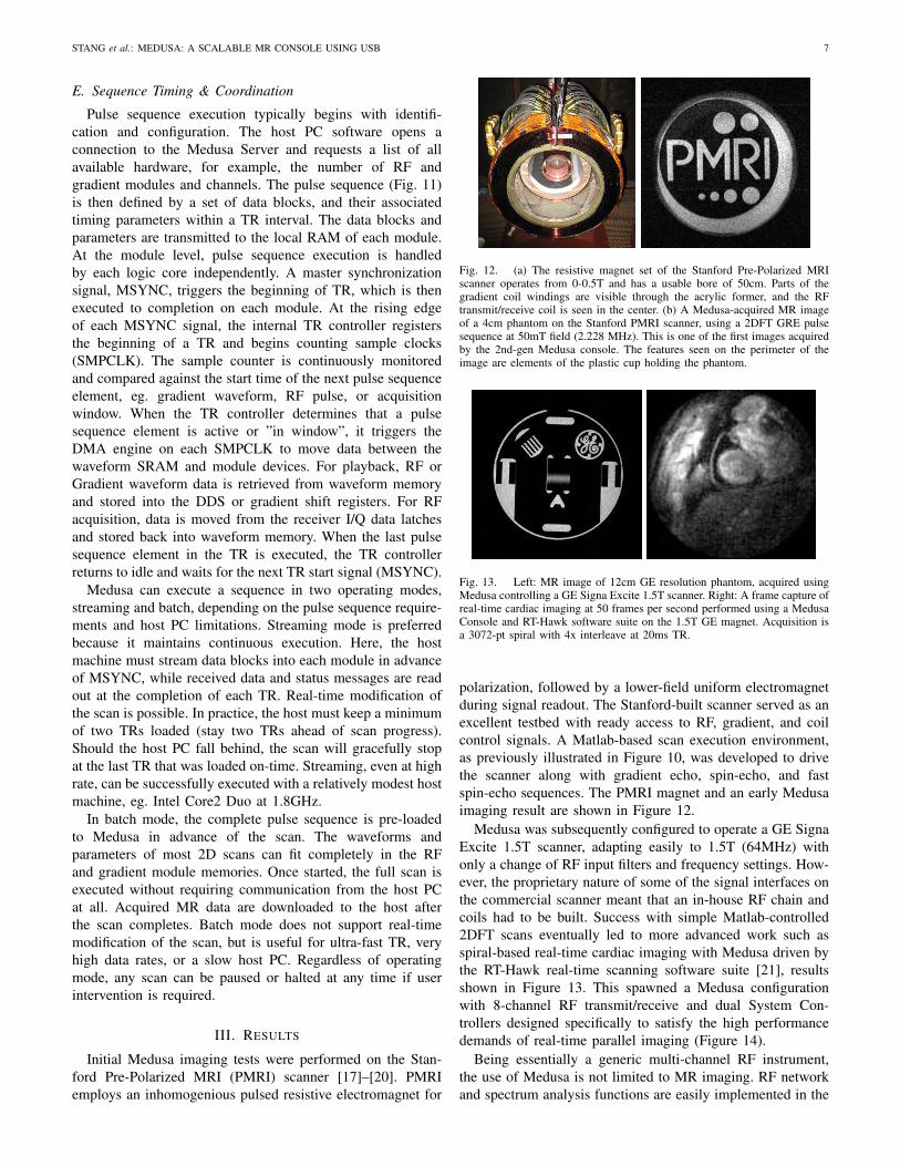
Fig. 12. (a) The resistive magnet set of the Stanford Pre-Polarized MRIscanner operates from 0-0.5T and has a usable bore of 50cm. Parts of thegradient coil windings are visible through the acrylic former, and the RFtransmit/receive coil is seen in the center. (b) A Medusa-acquired MR imageof a 4cm phantom on the Stanford PMRI scanner, using a 2DFT GRE pulsesequence at 50mT field (2.228 MHz). This is one of the first images acquiredby the 2nd-gen Medusa console. The features seen on the perimeter of theimage are elements of the plastic cup holding the phantom.
Fig. 13. Left: MR image of 12cm GE resolution phantom, acquired usingMedusa controlling a GE Signa Excite 1.5T scanner. Right: A frame capture ofreal-time cardiac imaging at 50 frames per second performed using a MedusaConsole and RT-Hawk software suite on the 1.5T GE magnet. Acquisition isa 3072-pt spiral with 4x interleave at 20ms TR.
polarization, followed by a lower-field uniform electromagnetduring signal readout. The Stanford-built scanner served as anexcellent testbed with ready access to RF, gradient, and coilcontrol signals. A Matlab-based scan execution environment,as previously illustrated in Figure 10, was developed to drivethe scanner along with gradient echo, spin-echo, and fastspin-echo sequences. The PMRI magnet and an early Medusaimaging result are shown in Figure 12.
Medusa was subsequently configured to operate a GE SignaExcite 1.5T scanner, adapting easily to 1.5T (64MHz) withonly a change of RF input filters and frequency settings. How-ever, the proprietary nature of some of the signal interfaces onthe commercial scanner meant that an in-house RF chain andcoils had to be built. Success with simple Matlab-controlled2DFT scans eventually led to more advanced work such asspiral-based real-time cardiac imaging with Medusa driven bythe RT-Hawk real-time scanning software suite [21], resultsshown in Figure 13. This spawned a Medusa configurationwith 8-channel RF transmit/receive and dual System Con-trollers designed specifically to satisfy the high performancedemands of real-time parallel imaging (Figure 14).
Being essentially a generic multi-channel RF instrument,the use of Medusa is not limited to MR imaging. RF networkand spectrum analysis functions are easily implemented in the
STANG et al.: MEDUSA: A SCALABLE MR CONSOLE USING USB 8
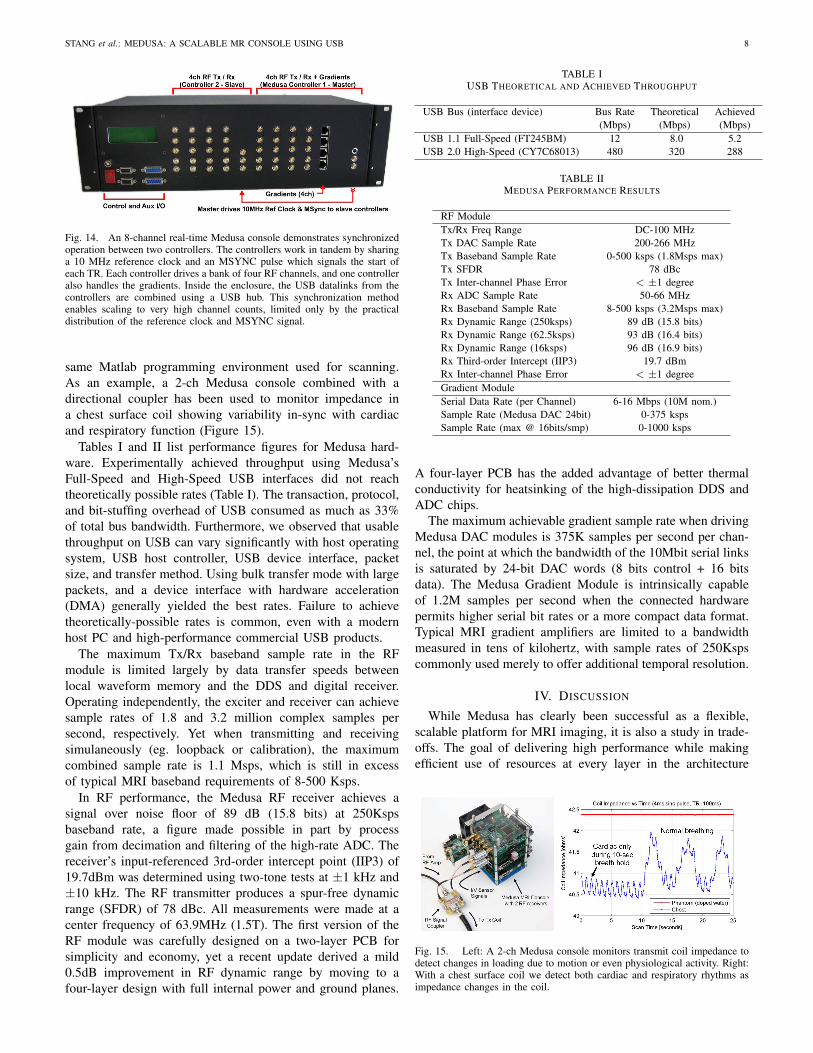
Fig. 14. An 8-channel real-time Medusa console demonstrates synchronizedoperation between two controllers. The controllers work in tandem by sharinga 10 MHz reference clock and an MSYNC pulse which signals the start ofeach TR. Each controller drives a bank of four RF channels, and one controlleralso handles the gradients. Inside the enclosure, the USB datalinks from thecontrollers are combined using a USB hub. This synchronization methodenables scaling to very high channel counts, limited only by the practicaldistribution of the reference clock and MSYNC signal.
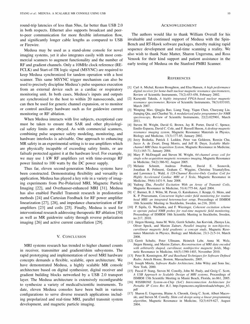
same Matlab programming environment used for scanning.As an example, a 2-ch Medusa console combined with adirectional coupler has been used to monitor impedance ina chest surface coil showing variability in-sync with cardiacand respiratory function (Figure 15).
Tables I and II list performance figures for Medusa hard-ware. Experimentally achieved throughput using Medusa’sFull-Speed and High-Speed USB interfaces did not reachtheoretically possible rates (Table I). The transaction, protocol,and bit-stuffing overhead of USB consumed as much as 33%of total bus bandwidth. Furthermore, we observed that usablethroughput on USB can vary significantly with host operatingsystem, USB host controller, USB device interface, packetsize, and transfer method. Using bulk transfer mode with largepackets, and a device interface with hardware acceleration(DMA) generally yielded the best rates. Failure to achievetheoretically-possible rates is common, even with a modernhost PC and high-performance commercial USB products.
The maximum Tx/Rx baseband sample rate in the RFmodule is limited largely by data transfer speeds betweenlocal waveform memory and the DDS and digital receiver.Operating independently, the exciter and receiver can achievesample rates of 1.8 and 3.2 million complex samples persecond, respectively. Yet when transmitting and receivingsimulaneously (eg. loopback or calibration), the maximumcombined sample rate is 1.1 Msps, which is still in excessof typical MRI baseband requirements of 8-500 Ksps.
In RF performance, the Medusa RF receiver achieves asignal over noise floor of 89 dB (15.8 bits) at 250Kspsbaseband rate, a figure made possible in part by processgain from decimation and filtering of the high-rate ADC. Thereceiver’s input-referenced 3rd-order intercept point (IIP3) of19.7dBm was determined using two-tone tests at ±1 kHz and±10 kHz. The RF transmitter produces a spur-free dynamicrange (SFDR) of 78 dBc. All measurements were made at acenter frequency of 63.9MHz (1.5T). The first version of theRF module was carefully designed on a two-layer PCB forsimplicity and economy, yet a recent update derived a mild0.5dB improvement in RF dynamic range by moving to afour-layer design with full internal power and ground planes.
TABLE IUSB THEORETICAL AND ACHIEVED THROUGHPUT
USB Bus (interface device) Bus Rate Theoretical Achieved(Mbps) (Mbps) (Mbps)
USB 1.1 Full-Speed (FT245BM) 12 8.0 5.2USB 2.0 High-Speed (CY7C68013) 480 320 288
TABLE IIMEDUSA PERFORMANCE RESULTS
RF ModuleTx/Rx Freq Range DC-100 MHzTx DAC Sample Rate 200-266 MHzTx Baseband Sample Rate 0-500 ksps (1.8Msps max)Tx SFDR 78 dBcTx Inter-channel Phase Error < ±1 degreeRx ADC Sample Rate 50-66 MHzRx Baseband Sample Rate 8-500 ksps (3.2Msps max)Rx Dynamic Range (250ksps) 89 dB (15.8 bits)Rx Dynamic Range (62.5ksps) 93 dB (16.4 bits)Rx Dynamic Range (16ksps) 96 dB (16.9 bits)Rx Third-order Intercept (IIP3) 19.7 dBmRx Inter-channel Phase Error < ±1 degreeGradient ModuleSerial Data Rate (per Channel) 6-16 Mbps (10M nom.)Sample Rate (Medusa DAC 24bit) 0-375 kspsSample Rate (max @ 16bits/smp) 0-1000 ksps
A four-layer PCB has the added advantage of better thermalconductivity for heatsinking of the high-dissipation DDS andADC chips.
The maximum achievable gradient sample rate when drivingMedusa DAC modules is 375K samples per second per chan-nel, the point at which the bandwidth of the 10Mbit serial linksis saturated by 24-bit DAC words (8 bits control + 16 bitsdata). The Medusa Gradient Module is intrinsically capableof 1.2M samples per second when the connected hardwarepermits higher serial bit rates or a more compact data format.Typical MRI gradient amplifiers are limited to a bandwidthmeasured in tens of kilohertz, with sample rates of 250Kspscommonly used merely to offer additional temporal resolution.
IV. DISCUSSION
While Medusa has clearly been successful as a flexible,scalable platform for MRI imaging, it is also a study in trade-offs. The goal of delivering high performance while makingefficient use of resources at every layer in the architecture
Fig. 15. Left: A 2-ch Medusa console monitors transmit coil impedance todetect changes in loading due to motion or even physiological activity. Right:With a chest surface coil we detect both cardiac and respiratory rhythms asimpedance changes in the coil.
STANG et al.: MEDUSA: A SCALABLE MR CONSOLE USING USB 9
has been addressed partly through initial design, and partlythrough iteration.
The proof-of-concept prototype highlighted several designpitfalls including insufficient RF and Gradient sample rates dueto underpowered microcontrollers, undersized memory buffers,and the low throughput of USB Full Speed (12Mbit/sec).The loose hardware integration of development kits alsomade multi-channel scale-up difficult. The second-generationMedusa system addressed many of these problems.
By implementing a common logic core to handle hard real-time tasks common to all Medusa modules, we simultaneouslyabsolved the Medusa Controller and host PC from dealingwith precision timing while also simplifying system design,lowering cost, and promoting system modularity and expand-ability. Hard real-time tasks are contained and remain local tothe modules. New or upgraded modules added to the Medusasystem can build upon the same logic core (or implement anew compliant one) along with the circuits to support newfunctionality. Already, the Medusa Gradient module hardwarehas been easily reconfigured in firmware to drive severaldifferent gradient systems including GE and Varian digitally-driven amplifiers, as well as in-house built RF vector multiplierboards in place of the standard Medusa DAC boards.
Likewise, the use of digital RF components yields somekey design advantages and simplifications. Performing down-mixing and channel filtering numerically ensures that multi-channel systems have perfectly matched response withoutdrift due to temperature or component aging. Digitizing RFearly also means fewer analog parts in the receive path thatmust be scrutinized for linearity, dynamic range, and IP3performance. Direct digital conversion of RF eliminates theneed to distribute a local oscillator (LO) common in analogimplementations. However, digital systems do not escape theneed for quality phase and frequency references. The lowphase noise requirement on analog LO signals have an exactcorrollary in the clock jitter specification levied on high-speeddigital sampling clocks. In both cases, a poor quality referencewill lead to unwanted spectral broadening and reduced SNRin the baseband, e.g. clock jitter of just 300 femtoseconds isequivalent to the loss of the least-significant bit on Medusa’s14-bit ADC when acquiring a 64MHz signal.
We see from results (Table II) that the Medusa RF receiverclosely tracks predicted process gain from oversampling. Forsinusoids with random noise, we can expect oversamplingby factor N to yield log2(N)/2 additional bits of dynamicrange. At lower imaging bandwidths, the receiver’s noise-freedynamic range already exceeds the range provided by the 16-bit output data path. A future upgrade of the receiver ADC inspeed or bit-depth would need to be accompanied by a 20 or24-bit digital path to capture the wide dynamic range.
The performance of digital RF components such as DDSand high-speed ADCs are advancing rapidly. Already, thedevices used in the Medusa RF module are old, supersededby newer ICs with a broader frequency range, faster samplingand update rates, and higher dynamic range. Far from makingMedusa obsolete, this merely reinforces the importance ofthe modular system architecture which permits the seamlessupgrade of components as technology improves and needs
grow.Building the Medusa System Controller separately from the
RF and Gradient modules succeeded in minimizing hardwareand allowing easy expansion and upgrade of the modules, butthis came at the price of introducing a potential data bottleneckin the Medusa backbone bus. Future Medusa designs may needto balance the increasing data demands of high channel countsagainst ultimate modularity. For example, a single RF Modulehosting 4 or 8 channels could produce enough data that italone would fill a USB 2.0 data link. For such a design, theRF module should integrate System Controller functionalitywith a dedicated data link.
Moreover, there remains a question of whether USB is thebest bus architecture for Medusa. USB is ubiquetous, fast,cost-efficient, and intrinsically supports multiple devices perbus. By virtue of being entirely host managed, USB does notsuffer from bus collisions and can provide guaranteed datadelivery. While Medusa is now able to saturate a single USB2.0 480Mb/s link under real-time multi-channel operation, theintroduction of USB 3.0 at 4.8Gb/s may provide a compellingupgrade path with backwards compatibility. Multiple Medusasystems working in tandem have already been demonstratedas a method for increasing channel counts. A USB 3.0 hubcan aggregate the data from at least ten Medusa systems eachwith 4 to 8 RF channels, permitting an order of magnitudeincrease in channel count without any hardware redesign.
Nonetheless, USB is not without flaws. Protocol overhead is10-15 percent, and host-managed bus scheduling often reducesusable bandwidth an additional 10-25 percent. Commonlyachievable user data rates are only 60% of the raw bus rate,with relatively long round-trip latencies of 300us to 3ms.The lack of support for broadcast, multicast, and peer-to-peer device communication presents an efficiency and logis-tics problem when distributing global information amongst adistributed system like the Medusa architecture. Consider forexample the need to distribute a time-critical pulse sequencechange due to cardiac trigger. On USB, the message mustbe sent independently to each Medusa Controller, introducingdelay and time skew.
The IEEE 1394a/b bus standard (Firewire 400/800 Mbps)was considered early on as an alternative bus transport toUSB. Even when running at a bitrate slower than USB 2.0,Firewire achieves higher data throughput with up to 95% busutilization and guaranteed bandwidth. Yet Firewire began asa closed standard and despite clear technical advantages stillhas limited market share compared to USB. As a result, thereare far fewer components, tools, and resources for Firewiredevice development, making implementation challenging.
Gigabit Ethernet, although more complex to implementthan USB 2.0, presents some advantages for future Medusahardware generations. Like USB, multiple Ethernet links canbe aggregated into a high-bandwidth backbone using networkswitches. Ethernet network cards and switches are commonlyengineered and specified for high network load and are readilyavailable commercially at low cost. Most products can operateto over 90% network utilization. Tests of modern consumer-level PC hardware with built-in gigabit Ethernet achieved850Mb/s user data throughput when transferring to RAM, and
STANG et al.: MEDUSA: A SCALABLE MR CONSOLE USING USB 10
round-trip latencies of less than 50us, far better than USB 2.0in both respects. Ethernet also supports broadcast and peer-to-peer communication for more flexible information flow,and significantly longer cable lengths as compared to USBor Firewire.
Medusa may be used as a stand-alone console for novelimaging systems, yet it also integrates easily with most com-mercial scanners to augment functionality and the number ofRF and gradient channels. Only a 10MHz clock reference (RE-FCLK) and Start-of-TR logic signal (MSYNC) are required tokeep Medusa synchronized for tandem operation with a hostscanner. This same MSYNC trigger mechanism can also beused to precisely discipline Medusa’s pulse sequence executionfrom an external device such as a cardiac or respiratorymonitoring unit. In both cases, Medusa’s inputs and outputsare synchronized to the host to within 20 nanoseconds, andcan then be used for generic channel expansion, or to monitoror control auxiliary hardware such as for guidewire currentmonitoring or RF ablation.
When Medusa interacts with live subjects, exceptional caremust be taken to ensure that SAR and other physiologi-cal safety limits are obeyed. As with commercial scanners,combining pulse sequence safety modeling, monitoring, andhardware interlocks is advisable. One approach to enhancingMR safety in an experimental setting is to use amplifiers whichare physically incapable of exceeding safety limits, or arefailsafe protected against it at the hardware level. For example,we may use 1 kW RF amplifiers yet with time-average RFpower limited to 100 watts by the DC power supply.
Thus far, eleven second-generation Medusa systems havebeen constructed. Demonstrating flexibility and versatilty inapplication, Medusa has played a key role in a variety of imag-ing experiments from Pre-Polarized MRI, Magnetic ParticleImaging [22], and Overhauser-enhanced MRI [31]. Medusahas also enabled Parallel Transmit research in predistortionmethods [24] and Cartesian Feedback for RF power amplifierlinearization [27], [28], and impedance characterization of RFamplifiers [23] and coils [25]. Finally, Medusa is used forinterventional research addressing therapeutic RF ablation [30]as well as MR guidewire safety through reverse polarizationimaging [26] and active current cancellation [29].
V. CONCLUSION
MRI systems research has trended to higher channel countsin receiver, transmitter and gradient/shim subsystems. Therapid prototyping and implementation of novel MRI hardwareconcepts demands a flexible, scalable, open architecture. Wehave demonstrated Medusa, a highly scalable MR consolearchitecture based on digital synthesizer, digital receiver andgradient building blocks networked by a USB 2.0 transportlayer. The Medusa architecture is extensively reconfigurableto synthesize a variety of medical/scientific instruments. Todate, eleven Medusa consoles have been built in variousconfigurations to serve diverse research applications includ-ing prepolarized and real-time MRI, parallel transmit systemdevelopment, and magnetic particle imaging.
ACKNOWLEDGMENT
The authors would like to thank William Overall for hisinvaluable and continued support of Medusa with the Spin-Bench and RT-Hawk software packages, thereby making rapidsequence development and real-time scanning a reality. Wealso wish to thank Nate Matter, Sharon Ungersma, and RossVenook for their kind support and patient assistance in theearly testing of Medusa on the Stanford PMRI Scanner.
REFERENCES
[1] Carl A. Michal, Kesten Broughton, and Elsa Hansen, A high performancedigital receiver for home-built nuclear magnetic resonance spectrometers,Review of Scientific Instruments, 73(2):453-458, February 2002.
[2] Kazuyuki Takeda, A highly integrated FPGA-based nuclear magneticresonance spectrometer, Review of Scientific Instruments, 78(3):033103,March 2007.
[3] Wenping Mao, Qingjia Bao, Liang Yang, Yiqun Chen, Chaoyang Liu,Jianqing Qiu, and Chaohui Ye, A modularized pulse programmer for NMRspectroscopy, Review of Scientific Instruments, 22(2):025901, March2011.
[4] Steven M. Wright, David G. Brown, Jay R. Porter, David C. Spence,Emilio Esparza, David C. Cole, and F. Russell Huson, A desktop magneticresonance imaging system, Magnetic Resonance Materials in Physics,Biology and Medicine, 13(3):177-85, January 2002.
[5] Jerzy Bodurka, Patrick J. Ledden, Peter van Gelderen, Renxin Chu,Jacco A. de Zwart, Doug Morris, and Jeff H. Duyn, Scalable Multi-channel MRI Data Acquisition System, Magnetic Resonance in Medicine,51(1):165-71, January 2004.
[6] Mary P. McDougall and Steven M. Wright, 64-channel array coil forsingle echo acquisition magnetic resonance imaging, Magnetic Resonancein Medicine, 54(2):386-92, August 2005.
[7] Melanie Schmitt, Andreas Potthast, David E. Sosnovik,Jonathan R. Polimeni, Graham C. Wiggins, Christina Triantafyllou,and Lawrence L. Wald, A 128-Channel Receive-Only Cardiac Coil forHighly Accelerated Cardiac MRI at 3 Tesla, Magnetic Resonance inMedicine, 59(6):1431-9, June 2008.
[8] Yudong Zhu, Parallel Excitation With an Array of Transmit Coils,Magnetic Resonance in Medicine, 51(4):775-84, April 2004.
[9] C. Barmet, B. J. Wilm, M. Pavan, G. Katsikatsos, J. Keupp, G. Mens, andK. P. Pruessmann, Concurrent higher-order field monitoring for routinehead MRI: an integrated heteronuclear setup, Proceedings of ISMRM18th Scientific Meeting in Stockholm, Sweden, no.216, 2010.
[10] P. Sipila, G. Wachutka, and F. Wiesinger, Coherent excitation schemeto operate pulsed NMR probes for real-time magnetic field monitoring,Proceedings of ISMRM 18th Scientific Meeting in Stockholm, Sweden,no.217, 2010.
[11] Jurgen Hennig, Anna M. Welz, Gerrit Schultz, Jan Korvink, Zhenyu Liu,Oliver Speck, and Maxim Zaitsev, Parallel imaging in non-bijective,curvilinear magnetic field gradients: a concept study, Magnetic Reso-nance Materials in Physics, Biology and Medicine, 21(1-2):5-14, March2008.
[12] Gerrit Schultz, Peter Ullmann, Heinrich Lehr, Anna M. Welz,Jurgen Hennig, and Maxim Zaitsev, Reconstruction of MRI data encodedwith arbitrarily shaped, curvilinear, nonbijective magnetic fields, Mag-netic Resonance in Medicine, 64(5):1390-1403, November 2010.
[13] Peter B. Kennington, RF and Baseband Techniques for Software DefinedRadio, Artech House, Boston, Massachusetts, 2005.
[14] Joseph Mitola, Software Radio Architecture, John Wiley and Sons Inc,New York, 2000.
[15] Pascal P. Stang, Steven M. Conolly, John M. Pauly, and Greig C. Scott,A USB Approach to Scalable Design of MRI systems, Proceedings ofISMRM 13th Scientific Meeting in Miami Beach, Florida, no.861, 2005.
[16] WISHBONE System-on-Chip (SoC) Interconnection Architecture forPortable IP Cores Rev B.3, http://opencores.org/downloads/wbspec b3.pdf
[17] Sharon E. Ungersma, Blaine A. Chronik, Greig C. Scott, Albert Macov-ski, and Steven M. Conolly. Shim coil design using a linear programmingalgorithm, Magnetic Resonance in Medicine, 52(3):619-627, August2004.
STANG et al.: MEDUSA: A SCALABLE MR CONSOLE USING USB 11
[18] Nathaniel I. Matter, Greig C. Scott, Ross D. Venook,Sharon E. Ungersma, Thomas Grafendorfer, Albert Macovski, andSteven M. Conolly. Three-dimensional prepolarized magnetic resonanceimaging using rapid acquisition with relaxation enhancement, MagneticResonance in Medicine, 56(5):1085-1095, 2006.
[19] Sharon E. Ungersma, Nathaniel I. Matter, Jonathan W. Hardy,Ross D. Venook, Albert Macovski, Steven M. Conolly, and Greig C. Scott.Magnetic resonance imaging with T1 dispersion contrast Magnetic Res-onance in Medicine, 55(6):1362-1371, 2006.
[20] Ross Venook, Nathaniel Matter, Meena Ramachandran,Sharon Ungersma, Garry Gold, Nicholas Giori, Albert Macovski,Greig Scott, and Steven Conolly. Prepolarized MRI around metalorthopedic implants, Magnetic Resonance in Medicine, 56:177-286,2006.
[21] Juan Santos, Graham A. Wright, and John M. Pauly, Flexible real-timemagnetic resonance imaging framework, Proceedings of IEEE Engineer-ing in Medicine and Biology Society, 2:1048-51, 2004.
[22] Patrick W. Goodwill, Greig C. Scott, Pascal P. Stang, andSteven M. Conolly, Narrowband Magnetic Particle Imaging, IEEE Trans-actions on Medical Imaging, 28(8):1231-1237, 2009.
[23] Greig C. Scott, Pascal P. Stang, Adam Kerr, John M. Pauly, A LoadPull/Hot S22 Analyzer for Transmit Array Amplifiers, Proceedings ofISMRM 17th Scientific Meeting, Honolulu, Hawaii, no.3025, 2009.
[24] Pascal P. Stang, John M. Pauly, and Greig C. Scott, Vector Iterative Pre-Distortion: An Auto-calibration Method for Transmit Arrays, Proceedingsof ISMRM 18th Scientific Meeting in Honolulu, Hawaii, no.491, 2009.
[25] Pascal P. Stang, John M. Pauly, and Greig C. Scott, A Versatile In-Line Sensor For Power Monitoring and Calibration of Transmit Arrays,Proceedings of ISMRM 18th Scientific Meeting in Honolulu, Hawaii,no.494, 2009.
[26] William R. Overall, John M. Pauly, Pascal P. Stang, Greig C. Scott,Ensuring safety of implanted devices under MRI using reversed RFpolarization, Magnetic Resonance in Medicine, 64(3):823-833, 2010.
[27] Marta G. Zanchi, Pascal P. Stang, Adam A. Kerr, John M. Pauly, andGreig C. Scott, Frequency-Offset Cartesian Feedback for MRI Power Am-plifier Linearization, IEEE Transactions on Medical Imaging, 30(2):512-22, 2011.
[28] Marta .G. Zanchi, Pascal P. Stang, Johm M. Pauly, and Greig C. Scott,Tuning the Output Impedance of RF Power Amplifiers with Frequency-Offset Cartesian Feedback, Proceedings of ISMRM 18th Scientific Meet-ing, Stockholm, Sweden, 2010.
[29] Maryam Etezadi-Amoli, Pascal Stang, Marta G. Zanchi, John M. Pauly,Greig C. Scott, and Adam B. Kerr, Controlling induced currents inguidewires using parallel transmit, Proceedings of ISMRM 18th ScientificMeeting, Stockholm, Sweden, 2010.
[30] Kim Shultz, Pascal P. Stang, John M. Pauly, Greig C. Scott, Feasibilityof RF Ablation at the Larmor Frequency for RF Field Visualization,Proceedings of ISMRM 19th Scientific Meeting, Montreal, Canada,no.1760, 2011.
[31] Kang-Hyun Ahn, Greig Scott, Pascal Stang, Steve Conolly, and Dim-itre Hristov, Multiparametric Imaging of Tumor Oxygenation, RedoxStatus, and Anatomical Structure Using Overhauser-Enhanced MRI Pre-polarized MRI System, Magnetic Resonance in Medicine, 65(5):1416-1422, 2011.