Embed Size (px)
Citation preview
Stanford University – Facilities Design Guidelines
February 2018 Page 1 of 14 2018 FDG Section 07 60 00
SECTION 07 60 00
FLASHING AND SHEET METAL
PART 1 - GENERAL
1.1. RELATED DOCUMENTS:
A. Drawings and general provisions of Contract, including General and Supplementary Conditions and other Division-l Specification sections, apply to work of this section.
1.2 GENERAL
A. This portion of the specification sets forth the general requirements and describes materials and workmanship for installing the flashings and sheet metal on the cold applied built-up roofing system.
B. All materials described herein shall be furnished and installed by the roofing contractor unless specifically noted otherwise.
C. Work shall be in accordance with Architectural Sheet Metal Manual, Fifth Edition, as issued by Sheet Metal and Air Conditioning Contractors' National Association, Inc., (SMACNA)
PART 2 - PRODUCTS
2.1. METAL FLASHING
A. Shop fabricated metal components including; metal edge-gravel stops, counter-flashing, parapet wall copings, scuppers, skirt flashing, area divider covers, expansion joint covers, etc.
1. Twenty-two (22) gauge minimum, sheet steel; commercial quality, ASTM A 526 lock forming quality, Kynar 500 coating finish, color to be determined by Stanford.
B. Metal Pipe-jack Flashing: 24 gauge galvanized steel pipe-jack flashing with integral roof flange.
C. Plumbing Vents, Covers and Drains: ASTM B29, four (4) lb sheet lead. Custom made and sized lead flashing jacks and covers are required for all standpipes. Sheet lead shall be used for drain flashings only.
2.2. DRAINS
A. Cast iron bowl main roof drain assembly with cast iron roof membrane clamping ring and metal leaf screen by Zurn, Josam or approved equal. Diameter to match existing and conform to local plumbing codes.
Stanford University – Facilities Design Guidelines
February 2018 Page 2 of 14 2018 FDG Section 07 60 00
2.3. FLASHING MEMBRANE:
A. Flashing ply sheet: ASTM D 146, coated, polyester core base sheet.
Test Typical Value Test Method
______________________________________________________________________________
Tensile Strength
• Machine Direction 100lbf ASTMDl46
• Cross Machine Direction 85 Ibf
Elongation
• Machine Direction 45 % ASTM D 146
• Cross Machine Direction 50 %
Asbestos Content 0% EPA600/M4-82-020
Fire Resistance Pass, Class A ASTM E 108/UL 790
Thickness 60 mils ASTM D 1777
Pliability Pass ASTMD 146
Asphalt 20bs/SQ ASTM D 146
Surfacing 3.0 Ibs/SQ ASTM D 146
Roll Dimensions 39-1/2" x 67' ASTM D 146
Average Roll Weight 611bs. ASTM D 146
Compatibility of Felt Coating With Oliensis Test, No Exudate ASTM D 1370
Asphalt Roofing Bitumen
Average Minimum Adhesion Strength ASTM D 1876
to Felt Coating After Conditioning:
1) 24 Hrs. @ 73Deg F 12.91bf/in.
2) 7 Days @ 73°F 12.5 lbf/in.
3) 30 Days @ 73°F 10.7 lbf/in.
4) 6 Months @ 73°F 13.0 lbf/in.
5) I Year @ 73°F 9.31bf/in.
Penetration 15 units ASTM D 5
Stanford University – Facilities Design Guidelines
February 2018 Page 3 of 14 2018 FDG Section 07 60 00
Softening Point 217 Deg F ASTM D 36
Cold Temperature Bend 20°F, 1/4" Rod ASTM D 3111
Rubber Modifier SEBS Shell Kraton G
Gel Permeation (styrene-ethylene- Chromatography
butylene-styrene)
B. Cap Sheet: 2.8 mm, Granule Surface, Modified Bitumen, Surface Membrane.
Test Typical Value Test Method ______________________________________________________________________________
Thickness, mils (mm) 110 (2.80) ASTM D 5147
Elongation at Max. Load,O +- 3.6Deg. F (-18 +-2 Deg. C), % ASTMD 5147
MD/XMD 3.0/3.0
Ultimate Elongation at 73.4 +- 3.6Deg.F (23 +- 2°C), % ASTM D 5147
MD/XMD 5.0/6.0
Tear Strength at 73.4:+- 3.6°F (23+- 2°C), lbf(N) ASTM D 5147
MD/XMD 55 (245)/70 (311)
Asbestos Content % Zero EPA600/M4-82-020
Fire Resistance Pass, Class A ASTM E 108/UL 790
PART 3 - EXECUTION 3.1. GENERAL FLASHING REQUIREMENTS
A. Preparation:
1. Remove existing flashing materials to substrate. 2. Prime vertical substrate with asphalt primer at approximate
rate of one gallon per 200 sq. ft.
Stanford University – Facilities Design Guidelines
February 2018 Page 4 of 14 2018 FDG Section 07 60 00
3. Install new roofing two inches beyond top edge of cant.
B. Base ply(s):
1. Fully adhere one ply flashing base membrane completely to flashing substrate, cant and roofing in continuous and uniform layer of asphalt mastic.
C. Flashing ply:
1. Fully adhere a top layer of flashing membrane over base p1y(s) in a uniform and continuous layer of asphalt mastic.
2. Mechanically fasten top of flashing to substrate, fasten minimum of 8 inches on center
3. Seal top edge with a 4 inch wide stripping membrane embedded in alternating courses of asphalt mastic.
4. Strip in bottom edge of flashing with 4 inch wide stripping membrane and specified asphalt mastic.
D. Install specified counter flashing system as per detail drawings.
E. Set flanges in asphalt mastic. Seal flanges with two (2) plies of reinforcing membrane embedded between alternating applications of mastic. Extend first ply 4" beyond flange; second ply 2".
F. Metal Skirt Extensions: Wherever existing counter flashing, sleeper covers or curb mounted equipment flashings are not a minimum of 3 inches wide, fabricate and install an extension. Ensure extension is made from the same sheet materials as the other metal flashings and has a drip edge incorporated into its manufacture.
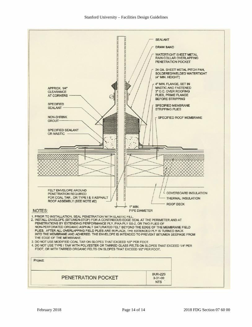
3.2. PITCH PANS
A. Install roofing system onto wood blocking. Apply uniformly thick layer of asphalt mastic to surface receiving metal flange.
B. Install specified pre-fabricated pitch pan around penetration. Prime metal flange, projection, and pitch pan interior with asphalt primer.
C. Nail flange to wood blocking three inches o.c., staggered.
D. Install two (2) ply stripping for metal flanges as described in section 3.1.E.
E. Install membrane cap sheet or surfacing.
F. Fill pitch pan to 3/4" from top with non-shrink grout allow to set up. Seal top of pitch pan with elastomeric mastic.
F. Install storm collar or watershed
Stanford University – Facilities Design Guidelines
February 2018 Page 5 of 14 2018 FDG Section 07 60 00
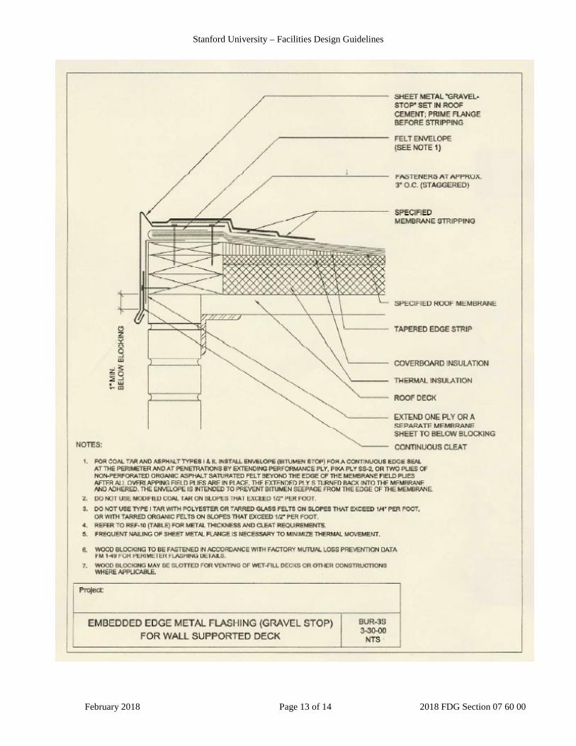
3.3. METAL EDGE
A. Install new roofing to blocking edge as required. Nail with spiral shank or annular shank nails, 8" o.c. Nails to have a 1" integral cap.
B. Prior to setting and nailing horizontal flanges of metal edge flashing, trowel a l/16 inch uniformly thick layer of asphalt mastic to roofing surface receiving metal flange.
C. Fabricate and install metal edge flashing with formed drip edge incorporating 3/4" lock. Secure fascia bottom with 3/4" lock to continuous cleat nailed 16" o.c. Cleat shall be 1 gauge heavier than fascia.
1. Gap fascia ends 1/2";overlap cleat joints 1". Set flange in mastic. Cover fascia ends with cover plate profiled to fascia. Set cover in elastomeric mastic; nail to wood blocking through gap between fascia joints.
2. Nail interior portion of flange to wood blocking 3" o.c. , staggered.
3. Prime metal flange with asphalt primer.
D. Install two (2) ply stripping for metal flanges as described in section 3.1E.
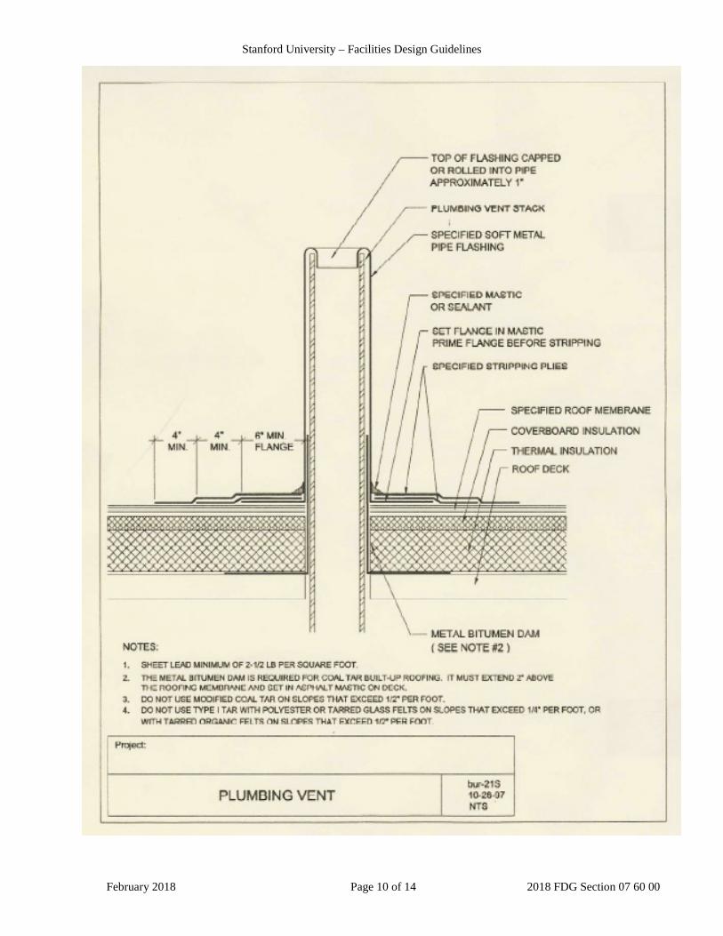
3.4. PLUMBING VENTS
A. Wedge plumbing vent tight against deck
B. Fabricate and install plumbing vent flashing from lead. Flange, four inches wide minimum, extend completely around periphery of vent flashing. Set flange into asphalt mastic. Neatly dress flange with wood block. Prime metal with asphalt primer.
C. Install two (2) ply stripping for metal flanges as described in section 3.1.E.
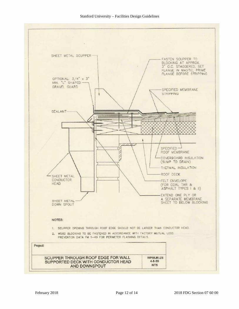
3.5. SCUPPERS
A. Install cant strip as specified to scupper opening
B. Extend new roofing at least two inches beyond top edge of cant Nail six inches o.c. with cap nails.
C. Install specified pre-manufactured scupper in a uniform and continuous layer of mastic. Install scupper head below outside of port and new downspouts as required.
D. Prime metal surfaces to receive flashing membrane.
E. Install modified bitumen base flashing as described in section 3.1.
Stanford University – Facilities Design Guidelines
February 2018 Page 6 of 14 2018 FDG Section 07 60 00
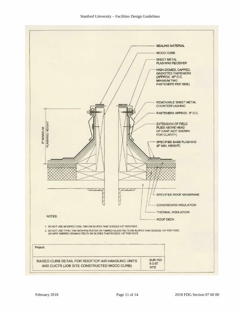
3.6. WOOD CURBS
A. Remove mechanical equipment from curb.
B. Extend new roofing at least two inches beyond top edge of cant. Nail six inches o.c. with cap nails.
C. Install modified bitumen base flashing as described in section 3.1
D. Fabricate and install counter flashing/skirt flashing as required
E. Reinstall mechanical equipment onto curb. Refasten
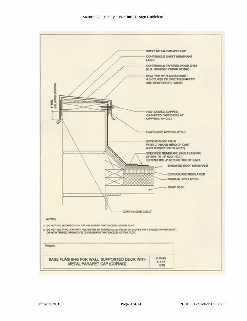
3.7. COPINGS
A. Install wood blocking. Fasten along top edge of wall, ensuring flush will sides of wall. Secure with specified fasteners; 24" o.c. . Drill and countersink bolts and washers.
B. Install continuous cleat on outside edge of blocking. Cleat shall be 1 gauge heavier than coping cover. Lap ends 1 inch. Nail 16 inches o.c.
C. Install shims to provide inward slope.
D. Place a water resistant membrane over top of parapet if membrane is not extended over. Extend a minimum of 2 inches down over edges of coping.
E. Fabricate and install coping cover. Connect coping sections with 1 1/4" standing seam. Extend front and rear sides 2 inches beyond wood blocking. Lower edges should have shop break to form drip edge.
Attach outside edge to cleat. Secure inside edge to wood blocking with specified fasteners 24 inches o.c. At corners, form standing seam and miter.
3.8. STORM COLLARS/PIPE FLASHINGS
A. Apply uniform thick layer of mastic to surface to receive flange.
B. Fabricate and install metal pipe flashing. Flange to extend completely around flashing periphery. Solder all joints. Double solder vertical joints.
C. Nail flange to wood blocking 3 inches o.c, staggered. Prime flange with asphalt primer.
D. Install two (2) ply stripping for metal flanges as described in section 3.1.E.
E. Fabricate storm collar with bolted connection. Cover pipe flashing 3 inches minimum. Tighten bolts. Prime surface with metal primer. Caulk projection/sheet metal interface. Provide watershed. Tool neatly.
Stanford University – Facilities Design Guidelines
February 2018 Page 7 of 14 2018 FDG Section 07 60 00
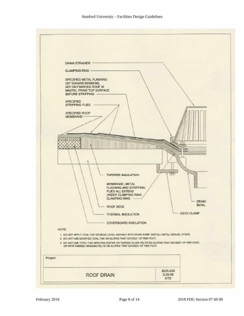
3.9. DRAINS
A. Install tapered edge strip around drain to create a 4'x4' sump area. Seal tapered edge with 3 course of mastic and reinforcing membrane. Install roofing system into sump and drain rim. Plug drain while roof work is being performed in area.
B. Prime lead flashing and apply in a uniform layer of asphalt mastic centered over drain. Extend lead 6 inches beyond rim. Neatly dress lead with wood block. Install two (2) ply stripping for metal flanges as described in section 3.1.G. Neatly cut lead to extend into bowl 1 inch.
C. Install cap sheet membrane. Neatly cut felts with drain at rim. Clamp clamping collar to drain in mastic
D. Remove plug if drain is working at the close of each day.
E. New drains shall have the service connection made to comp1y with all applicable building and plumbing codes.
END OF SECTION
Stanford University – Facilities Design Guidelines
February 2018 Page 8 of 14 2018 FDG Section 07 60 00
Stanford University – Facilities Design Guidelines
February 2018 Page 9 of 14 2018 FDG Section 07 60 00
Stanford University – Facilities Design Guidelines
February 2018 Page 10 of 14 2018 FDG Section 07 60 00
Stanford University – Facilities Design Guidelines
February 2018 Page 11 of 14 2018 FDG Section 07 60 00
Stanford University – Facilities Design Guidelines
February 2018 Page 12 of 14 2018 FDG Section 07 60 00
Stanford University – Facilities Design Guidelines
February 2018 Page 13 of 14 2018 FDG Section 07 60 00
Stanford University – Facilities Design Guidelines
February 2018 Page 14 of 14 2018 FDG Section 07 60 00


![Stanford Nano Shared Facilities | Stanford …€¦ · Web viewFind Tip (or Look around (Coarse tuning)). [ONLY TOP VIEW is shown] Adjust Photodiode. OMEGA: Click on Initial Tuning:](https://img.pdfslide.us/doc/110x75/5f3b30953461494d7a065cb1/stanford-nano-shared-facilities-stanford-web-view-find-tip-or-look-around-coarse.jpg)