1
Printed in Canada June 6, 2013 (#109499) Standpipe Piezometer Instructions For further information contact: Solinst Canada Ltd. Fax: +1 (905) 873-1992; (800) 516-9081 Tel: +1 (905) 873-2255; (800) 661-2023 35 Todd Road, Georgetown, Ontario Canada L7G 4R8 Web Site: www.solinst.com E-mail: [email protected] Model 601 Component List • Piezometer Tip lengths: 6", 1', 2', 3' (15 cm, 30 cm, 60 cm, 90 cm) To Complete an installation you will also need to source the following: • Plain End 3/4" Sch. 40 PVC Extensions (0.804"ID x 1.050"OD) (as required to reach desired depth) • Slip Couplings for Sch. 40 PVC Pipe (one required for each extension) • 3/4" Sch. 40 PVC Slip Cap • Optional Reducer Couplings (used to connect to other sizes of riser pipe) Operating Principles Standpipe Piezometers are designed for placement within a drilled hole to provide a filtered inlet point. Piezometers can also be manually pushed into suitable sediment, such as very loose sands at the base of a borehole, a stream, or into very loose tailings pond sediments. After the Standpipe Piezometer is installed to depth, ground- water enters through the porous filter and into the riser pipe, allowing water level monitoring, metals sampling, permeability measurements, slope stability tests, etc. The 60-micron filter in the 601 Piezometer is also ideal for air sparging and metals sampling. Installation 1. Ensure that all components are clean prior to use. 2. Push the first PVC extension into the slip coupling connected to the Piezometer Tip. 3. Add couplings and extensions until the desired length is reached, and install the Piezometer downhole. 4. After the Piezometer Tip and riser pipe are installed to depth, the installation can be completed by backfilling sand around the filtered Piezometer Tip and finished with sand, gravel or bentonite to the surface, depending on your application. Finish the installation with a slip cap on the top of the final PVC extension. Note: Avoid attempting to pull Model 601 Piezometers out of the soil after placement, since they are held together by friction fit only. 3/4" Sch. 40 PVC Extension Porous HDPE (Vyon) Filter PVC Body Slip Coupling Typical Standpipe Piezometer Installations Bentonite Grout Sand/Gravel Backfill Bentonite Seal Sand Filter 3/4" Sch. 40 PVC (Riser Pipe) Extensions Get Quote | More Info

Standpipe Piezometer Instrctions - Solinst in Canada une 03 (04) Standpipe Piezometer Instrctions or rter inormation contact Solinst anada td Fax: +1 (905) 873-1992; (800) 516-9081

  • Upload
    lenga

  • View
    221

  • Download
    0

Embed Size (px)

Citation preview

Printed in Canada June 6, 2013(#109499)

Standpipe Piezometer Instructions

For further information contact: Solinst Canada Ltd.Fax: +1 (905) 873-1992; (800) 516-9081 Tel: +1 (905) 873-2255; (800) 661-2023

35 Todd Road, Georgetown, Ontario Canada L7G 4R8Web Site: www.solinst.com E-mail: [email protected]

Model 601

Component List

• Piezometer Tip lengths: 6", 1', 2', 3' (15 cm, 30 cm, 60 cm, 90 cm)

To Complete an installation you will also need to source the following:

• Plain End 3/4" Sch. 40 PVC Extensions (0.804"ID x 1.050"OD) (as required to reach desired depth)

• Slip Couplings for Sch. 40 PVC Pipe (one required for each extension)

• 3/4" Sch. 40 PVC Slip Cap• Optional Reducer Couplings

(used to connect to other sizes of riser pipe)

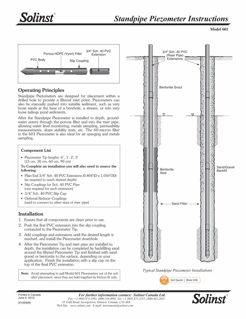
Operating PrinciplesStandpipe Piezometers are designed for placement within a drilled hole to provide a filtered inlet point. Piezometers can also be manually pushed into suitable sediment, such as very loose sands at the base of a borehole, a stream, or into very loose tailings pond sediments.

After the Standpipe Piezometer is installed to depth, ground-water enters through the porous filter and into the riser pipe, allowing water level monitoring, metals sampling, permeability measurements, slope stability tests, etc. The 60-micron filter in the 601 Piezometer is also ideal for air sparging and metals sampling.

Installation1. Ensure that all components are clean prior to use.2. Push the first PVC extension into the slip coupling

connected to the Piezometer Tip.3. Add couplings and extensions until the desired length is

reached, and install the Piezometer downhole. 4. After the Piezometer Tip and riser pipe are installed to

depth, the installation can be completed by backfilling sand around the filtered Piezometer Tip and finished with sand, gravel or bentonite to the surface, depending on your application. Finish the installation with a slip cap on the top of the final PVC extension.

Note: Avoid attempting to pull Model 601 Piezometers out of the soil after placement, since they are held together by friction fit only.

3/4" Sch. 40 PVC ExtensionPorous HDPE (Vyon) Filter

PVC Body Slip Coupling

Typical Standpipe Piezometer Installations

Bentonite Grout

Sand/Gravel BackfillBentonite

Seal

Sand Filter

3/4" Sch. 40 PVC (Riser Pipe) Extensions

Get Quote | More Info