Embed Size (px)
Citation preview
The author(s) shown below used Federal funds provided by the U.S. Department of Justice and prepared the following final report: Document Title: Standoff Detection of Concealed Weapons using
a Terahertz Illuminator with an Uncooled Imager Author: Lothar Moeller Document No.: 233347
Date Received: August 2011 Award Number: 2007-RG-CX-K013 This report has not been published by the U.S. Department of Justice. To provide better customer service, NCJRS has made this Federally-funded grant final report available electronically in addition to traditional paper copies.
Opinions or points of view expressed are those
of the author(s) and do not necessarily reflect the official position or policies of the U.S.
Department of Justice.
Standoff Detection of Concealed Weapons using a
Terahertz Illuminator with an Uncooled Imager
NIJ Award: 2007-RG-CX-K013
Summary
Reporting Period: October 2007 – March 2010
Lothar Moeller, PI
Bell Laboratories, Alcatel-Lucent, [email protected]
We summarize our main project activities, findings, and results made during the
‘reporting period’. In an effort to keep the report clearly arranged and within the given
space constrains, some details are left out, but described in our ‘Final Technical Report’.
The summary is organized by the technical aspects of the project. We document our
R&D work on the following:
• THz imager architecture, specification development, and THz source selection
• THz optics development, characterization, and imaging,
• Antireflection coatings for refractive THz optics
• THz microbolometer characterization
This document is a research report submitted to the U.S. Department of Justice. This report has not been published by the Department. Opinions or points of view expressed are those of the author(s) and do not necessarily reflect the official position or policies of the U.S. Department of Justice.
Introduction
The terror attack December, 25th, 2009 on Delta flight 253 brought to public awareness
significant security deficits at airports and the need for introducing ‘body scanners’ as
additional security measures. Generally, the increasing security requirements for public
spaces, especially airports but not limited to them, has resulted in strong interest in sensor
technologies capable of detecting concealed weapons. A suitable technology would allow
law enforcement officers to rapidly and reliably screen individuals or groups for
concealed threats without any physical contact or significant disruption of the suspect(s)
activities.
Potential threats could be guns, knifes, and explosives carried by a person underneath
clothing or hidden in baggage. Considering the large variety of shapes, viewing
orientations, and methods of disguise, these threats are best evaluated from direct
observation of images acquired by advanced sensor technologies. Furthermore, standoff
detection techniques, where suspects are screened at a distance, would provide an
intrinsic security margin for law enforcement personnel and could expedite the inspection
of larger scenes encompassing multiple suspects.
Terahertz waves can penetrate many non-metallic materials such as paper, cloth, and
leather and thus can be readily used in imaging detection systems suitable for concealed
weapon detection. However, to reliably distinguish handguns, knifes or bomb belts from
commonly carried objects such as cell phones, pens, and watches, high-resolution images
are required, which presents a severe challenge for today’s THz imaging technologies.
Our goal was to investigate and develop the fundamentals of a handheld THz imager for
concealed weapon detection. While stationary cabins for THz imaging are in operation,
This document is a research report submitted to the U.S. Department of Justice. This report has not been published by the Department. Opinions or points of view expressed are those of the author(s) and do not necessarily reflect the official position or policies of the U.S. Department of Justice.
e.g., at airports, embassies, etc., our focus is on designing a small, light-weight and
handheld instrument that can be carried by law enforcement officers during their
deployment.
In this project we have developed for such THz imagers two different kinds of optics, an
active illumination scheme, and detector technology after the imager performance was
specified under consideration of customer needs and architectural constraints.
1.0 Imager architecture and specification development
Two THz-imager architectures based on incoherent and coherent detection were under
consideration for achieving the program objectives. Both schemes have advantages but
differ in complexity.
In an incoherent architecture, a THz beam illuminates the object and the backscattered
THz signal is focused by the optics onto a THz detector array. A lens at the output of the
THz source, possibly designed as zone plate to enable zoom functions, allows for optimal
object illumination within areas of 60 cm and 20 cm diameter at approximately 10 m and
3m standoff distance, respectively. The imaging optics consists of at least two lenses to
achieve good spatial resolution across the image in the focal plane.
In a coherent architecture, the backscattered light is detected by superposing it with a
reference beam that possesses a fixed frequency relation to the backscattered light.
Although a coherent detector would gain about a factor of ~40 in sensitivity, such
architecture is currently infeasible, the project experience shows that commercially
available THz components are not mature enough to be integrated into reliable coherent
imaging schemes. In both architectures the illuminating beam would be 100% intensity
This document is a research report submitted to the U.S. Department of Justice. This report has not been published by the Department. Opinions or points of view expressed are those of the author(s) and do not necessarily reflect the official position or policies of the U.S. Department of Justice.
modulated to enable lock-in amplification on the detector side and background noise
suppression.
Several different objectives that can be combined with incoherent or coherent imager
technology were analyzed. We selected a two lenses Fresnel optics and a Cassegrain
type reflector as objectives for the experimental phase of the development. Both optics’
have intrinsic advantages with respect to several product relevant aspects e.g. low cost,
low loss, and compact size.
A literature search and discussions with law enforcement were used to develop
preliminary performance specifications that would satisfy the needs of various customers.
As a THz imager is a novel device, potential customers have not precisely determined the
best trade off between imager performance and SWAP (Size, Weight, And Power). The
imager’s aperture and spatial resolution are related through fundamental optics principles.
A small aperture lowers the spatial resolution and therefore the image quality. While the
required standoff operation distance is reasonably well established, parameters describing
the required imaging quality in terms of gray-scale resolution, spatial resolution, and size
are not readily available. Detection of concealed weapons up to 10 m distance would be
of high value and would cover several applications.
A 60 cm field of view at 10 m distance would allow for efficient screening of a standing
suspect’s cross section by pivoting the imager in a vertical scanning motion. At 3 m
distance the field of view is about 20 cm in diameter, large enough to image a handgun.
This document is a research report submitted to the U.S. Department of Justice. This report has not been published by the Department. Opinions or points of view expressed are those of the author(s) and do not necessarily reflect the official position or policies of the U.S. Department of Justice.
The specified spatial resolution requires about 60 detector pixels along the diameter of
the THz image.
The power budget of the imaging system was estimated by assuming 0.5 dB loss per lens,
1 dB propagation loss in 10 m air, 32 dB scattered light attenuation at 10 m distance for a
500 mm aperture optics, 35 dB power splitting loss per pixel, and a required minimum
illumination power of 640 pW per pixel to achieve 4-bit grayscale resolution at video
frame rates (detector NEP ~10pW/Sqrt(Hz)). A THz source with 10mW output power
would be sufficient to record images of weapons carried under shirts (~1 dB loss) at 10 m
distance.
The weight of the imager head should be less 10kg so that it can be attached to the
operator’s body (backpack). With our developed lenses we are approaching a weight
target of less than 4 kg which enables handheld operation of the imager.
2.0 THz source selection and optical component development
In the beginning of the project we selected as THz source supplier Teraphysics Inc. who
is designing 240 GHz and 650 GHz BWOs with output powers of about 40 mW for
different US funded R&D programs. While other suppliers offer non-handheld and heavy
BWOs (weight > 50kg) Teraphysics is the only company that plans to produce
miniaturized and strong THz sources. An alternative THz source (output power about 1
mW) consists of a frequency multiplier chain (FMC) based on Schottky diodes from
Virginia Diodes Inc. (VDI). At the time of our proposal submission, Teraphysics was
quite optimistic to get BWO prototypes for lab testing developed within the time frame of
our project. However, it turned out that Teraphysics underestimated the technological
This document is a research report submitted to the U.S. Department of Justice. This report has not been published by the Department. Opinions or points of view expressed are those of the author(s) and do not necessarily reflect the official position or policies of the U.S. Department of Justice.
challenges. In fact, during our project period no samples were available for testing.
During the first phase of the project we ordered from VDI a customized THz source that
outputs much less power than needed for THz imaging, but currently it is the best
available solution in terms of technical parameters.
Two concepts for the imager optics have been simulated, with the goal to design an
objective with the lowest possible complexity to minimize the development risks and
cost. Lens systems comprised of one or two elements were considered in order to keep
the complexity low. An analysis of single-lens optics with 50 cm aperture and reasonably
short focal lengths (<1m) shows that while it is possible to achieve the required spatial
resolution in the center of the image, diffraction effects degrade the image quality at its
edges. A two-lens-system is able to partially compensate for aberration effects leading to
a more evenly distributed spatial resolution across the focal plane while not significantly
reducing the image’s brightness. Relatively thick aperture lens might cause handling
problems of the imager head. A typical conventional lens' weight was estimated to be in
the 40-50 kg range. Fresnel-lens-based objectives offer a twofold advantage compared to
those containing condenser lenses as their thin body leads to weight reduction (several
tens of kg) and also to significantly reduced absorption loss. Also Fresnel lenses can be
manufactured in plastic material making the THz imager much more cost-effective when
produced in volume. While the principle of Fresnel optics is well understood, the
fabrication of large diameter lenses in low loss material is a new field and could be
problematic. Commercially available manufacturing techniques for medium-sized Fresnel
lenses are based on diamond-turning, milling, injection molding, and compression
This document is a research report submitted to the U.S. Department of Justice. This report has not been published by the Department. Opinions or points of view expressed are those of the author(s) and do not necessarily reflect the official position or policies of the U.S. Department of Justice.
molding. Each of these methods can offer advantages with respect to costs for
prototyping or large volume production, maximal manageable lens diameter, and the
selection of materials that are process suitable.
We simulated the Fresnel lenses with ZeMax EE software using its ‘Non-Sequential
Component’ mode which takes into account scatter effects occurring inside the lens. As
the THz imager operates with highly coherent sub-mm waves its diffraction performance
can be enhanced. Each groove (zone) of the lens can be aligned in height relative to its
flat bottom while keeping the surface curvature the same (phase matching).
Manufacturing tolerances (~2um) allow for this technique as they are small compared to
the effective wavelength (~300um). In our performance optimized design the primary
lens and the secondary lens have diameters of 51 cm and 32 cm, respectively and focal
lengths of 631 mm (large lens) and 1400 mm (small lens). The maximum thickness and
the groove depth are 5mm and 2mm, respectively. The lens manufacturing turned out to
be more challenging than estimated by Fresnel Technologies, Inc. TX, as the preparation
of the polypropylene raw material caused some surface curvature that hampered the
diamond-turning.
A verification by various geometrical measurements confirmed that all lens parameters
were within specified tolerances except for the bending of the large lens which was
slightly off but did not impair significantly imaging features.
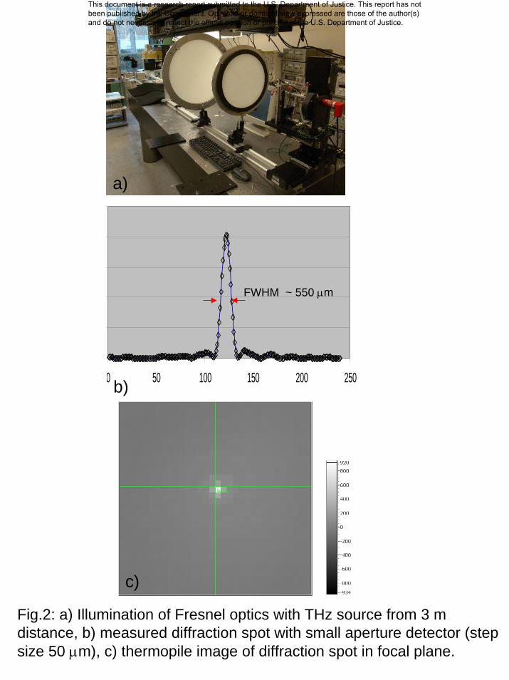
A horizontal scan in 50 um steps across the focal plane shows the intensity distribution
(fig. 2). The measured full-width-half-maximum (FWHM) value of approximately 11
steps or 550 um shows that our optics is diffraction limited and operates at the
theoretically best performance in terms of minimal possible spot size. An image taken
This document is a research report submitted to the U.S. Department of Justice. This report has not been published by the Department. Opinions or points of view expressed are those of the author(s) and do not necessarily reflect the official position or policies of the U.S. Department of Justice.
with a thermopile camera (pixel pitch 300 um) confirms the sharp focus of the optics. We
tested the imaging quality across the focal plane by moving the terahertz source
perpendicularly to the optical axis and found results that are consistent with simulations.
Due to the low sensitivity of the microbolometer and the comparatively weak source
signal, THz imaging could only be demonstrated under simplified experimental
conditions. When the THz source was placed close to the object (about 50 cm spacing) to
not further lose illumination power and the integration time of the lock-in amplifier was
set to 20 s in order to achieve strong noise filtering, images of crumpled aluminum foil
(high reflectivity) could be recorded at 3m stand-off distance with a signal to noise ratio
(SNR) of about 4 dB.
Development of reflective beam optics
Reflective beam optics has the intrinsic advantages of being less sensitive to standing
wave effects and can be built as a compact design. Among five analyzed objective types
we identified a modified Cassegrain optics with a working f-number of about 0.9 as most
suitable for our application.
The layout comprises a larger, concave, primary mirror and a smaller, convex, secondary
mirror that focus the incoming Terahertz radiation on the detector array, which is located
42mm behind the primary mirror (Fig.3) and consists of about 3600 (60 x 60) pixels
where each pixel has a size of 600 um x 600 um square. Adjustment of focus for an
object distance from 3 to 10m is achieved by moving the secondary mirror, while holding
fixed the primary mirror and detector array.
This document is a research report submitted to the U.S. Department of Justice. This report has not been published by the Department. Opinions or points of view expressed are those of the author(s) and do not necessarily reflect the official position or policies of the U.S. Department of Justice.
A contrast level of 0.02 is typically considered just barely resolvable by the human eye.
Therefore this optics, with a contrast level well above 0.15 throughout the entire range
from 0 to 0.5 cycles/mm, exhibits good resolution across the entire field-of-view as
Zemax simulations of the modulation transfer function shows.
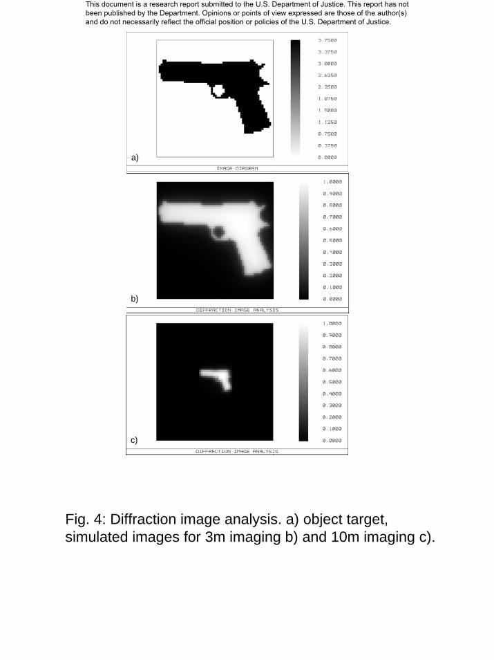
A more intuitive (albeit less quantitative) measure of imaging quality is obtained by
performing a diffraction image analysis of a sample target imaged through the system. In
order to graphically demonstrate the imaging capabilities of the optics, a picture of a
handgun was devised as object target (fig. 4). We scaled the target with 60 x 60 pixels so
that the handgun measures 7.0 inches across, approximately the actual size of a real
weapon. All details of the gun shape appear clearly in the diffraction image analysis for
the case of 3m imaging distance confirming the sufficiently fine resolution of the optics.
At an imaging distance of 10 m the gun appears as an object with approximately
triangular shape. However, when taking a closer look, more details are visible which
make an identification of the object as a weapon possible.
When operating with monochromatic visible light, coma, form errors, and surface
roughness appear as distinguishable error sources, which can be separately analyzed to
characterize the imaging features of the Cassegrain optics. As discovered during the
characterization, the primary mirror possesses an unexpectedly large form error resulting
in significant optical distortion despite careful alignment of the optical system. Several
optical tests were performed showing strong astigmatism and that the edge of the mirror
had a height variation of about 80 um. We speculate that spontaneous stress release inside
the mirror occurred when the reflector was dismounted from the flange of the diamond
This document is a research report submitted to the U.S. Department of Justice. This report has not been published by the Department. Opinions or points of view expressed are those of the author(s) and do not necessarily reflect the official position or policies of the U.S. Department of Justice.
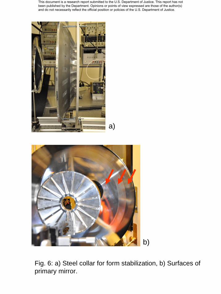
turning machine causing these deformations. Kaleido Technolgy re-evaluated the mirror
surface on their CMM machine, confirmed our findings, and diamond-turned the surface
again after stabilizing the mirror by gluing a steel collar on its back and filling cavities
with epoxy that attenuates possible mirror vibrations during milling. Also the spinning
speed was reduced which resulted in a smaller form error, but increased the surface
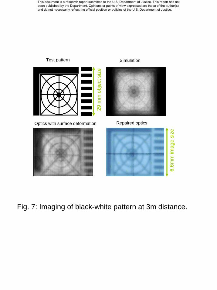
roughness. A black and white test pattern as shown in fig. 7 was projected and recorded
using a digital camera. Obviously, the image quality is significantly higher than before
repair and no higher order distortions are visible. Measured spot sizes and line widths of
HeNe laser light illuminated objects are agreeing reasonably well with simulations.
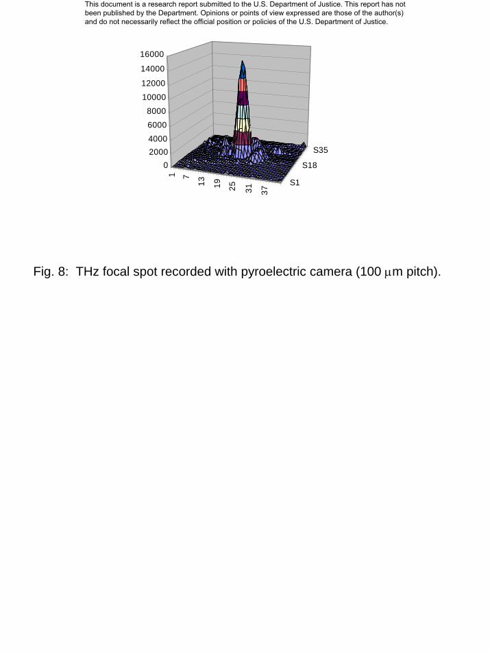
A pyroelectric camera with a pixel pitch of 100 µm (124 x 124 elements) is positioned in
the focal plane of the imager, and has a small spectral response in the THz and visible
wavelength range, which enables a fair comparison between optical and THz imaging
features of the Cassegrain optics. Horizontal and vertical intensity profiles indicate
diffraction effects caused by the limited aperture (fig. 8). The measured Airy radius is
about 0.56 mm which agrees well with simulation (0.57 mm). The small difference could
stem from reading inaccuracies caused by noisy patterns.
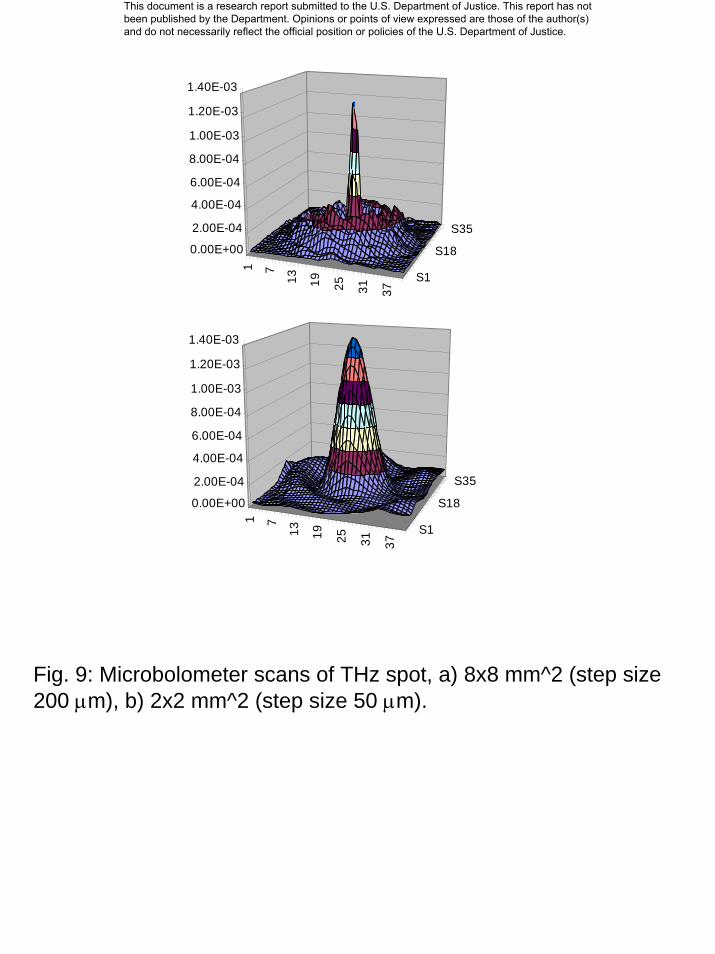
Microbolometer scans of 8mm x 8mm and 2mm x 2mm fields around the intensity
maximum indicate FWHMs of about 500 µm i.e. diffraction limited spot sizes (fig. 9).
However, side peaks appear with larger intensity than diffraction patterns from circular
apertures suggest. One reason for this could be that part of THz undergoes reflections
inside the detector chamber before it gets absorbed by the antenna of the bolometer.
This document is a research report submitted to the U.S. Department of Justice. This report has not been published by the Department. Opinions or points of view expressed are those of the author(s) and do not necessarily reflect the official position or policies of the U.S. Department of Justice.
Refractive Gaussian-to-tophat beam shaper (GTBS) for compact THz illuminator
We have considered several different designs for a beam optics needed to homogeneously
illuminate an object. A beam radiated from the horn antenna of our THz source possesses
in good approximation a Gaussian profile with an aperture angle of about 10 degrees
(vendor spec). However, for efficient illumination of an object a beam with uniform
intensity distribution across the FOV would be ideal if no THz power should be wasted.
Diffusers with radial increasing refraction power can convert a Gaussian profile into one
that approximates a rectangular shape and posses two aspheric surfaces needed to adjust
phase and amplitude of the source beam at the object plane.
To estimate the efficiency of refractive and diffractive GTBSs, we simulated a
homogenous object illumination across areas with a diameter of 0.135 m at 3 m and 0.45
m at 10 m distance. While thinner diffractive elements show lower absorption, refractive
GTBS can be manufactured with smaller fabrication errors and allow for applying an
additional antireflection structure. This results in a better overall efficiency for refractive
elements although their absorption losses are higher.
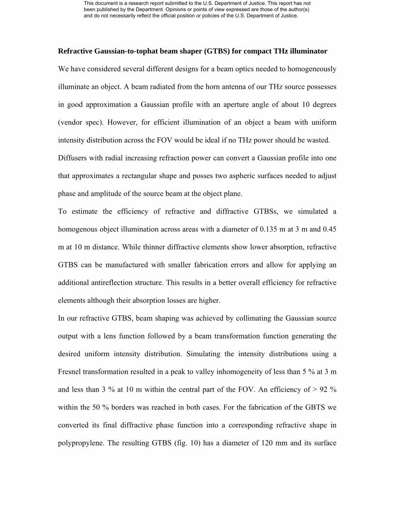
In our refractive GTBS, beam shaping was achieved by collimating the Gaussian source
output with a lens function followed by a beam transformation function generating the
desired uniform intensity distribution. Simulating the intensity distributions using a
Fresnel transformation resulted in a peak to valley inhomogeneity of less than 5 % at 3 m
and less than 3 % at 10 m within the central part of the FOV. An efficiency of > 92 %
within the 50 % borders was reached in both cases. For the fabrication of the GBTS we
converted its final diffractive phase function into a corresponding refractive shape in
polypropylene. The resulting GTBS (fig. 10) has a diameter of 120 mm and its surface
This document is a research report submitted to the U.S. Department of Justice. This report has not been published by the Department. Opinions or points of view expressed are those of the author(s) and do not necessarily reflect the official position or policies of the U.S. Department of Justice.
showed a peak-to-valley deviation from the calculated profile of about λ/10 and a Ra
roughness of about λ/100.
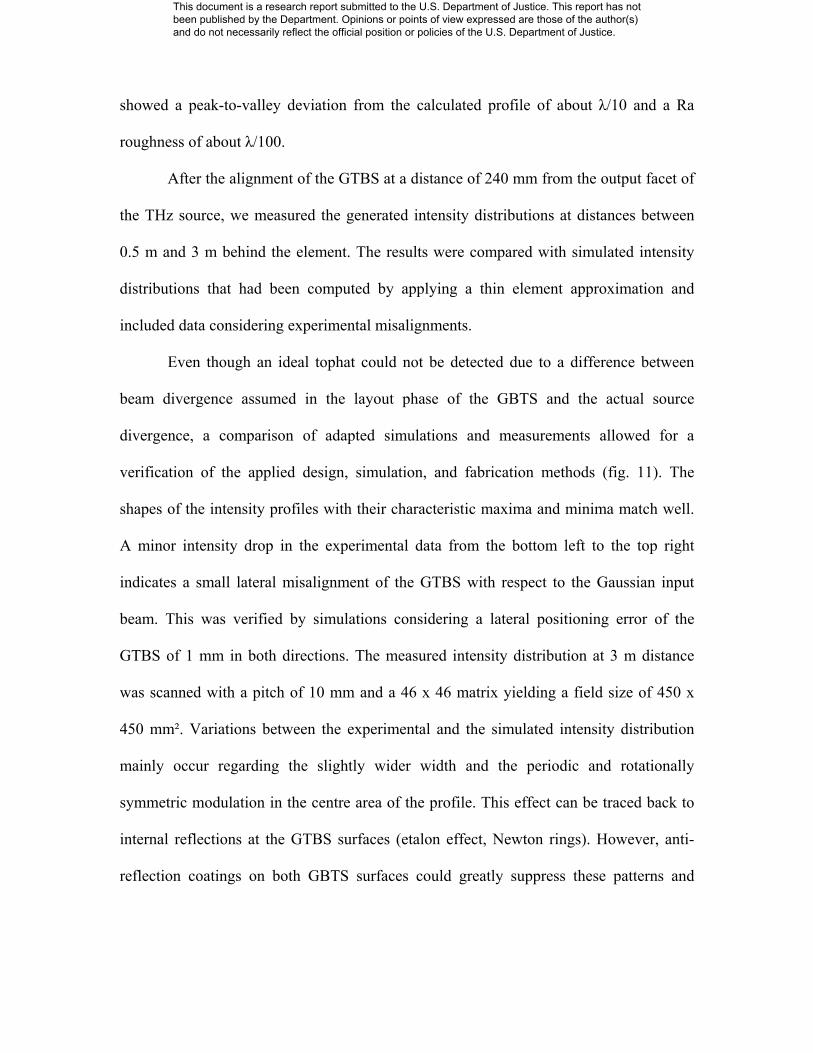
After the alignment of the GTBS at a distance of 240 mm from the output facet of
the THz source, we measured the generated intensity distributions at distances between
0.5 m and 3 m behind the element. The results were compared with simulated intensity
distributions that had been computed by applying a thin element approximation and
included data considering experimental misalignments.
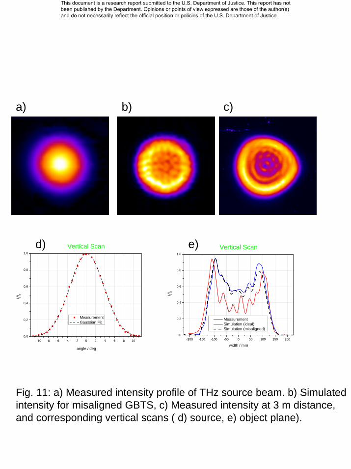
Even though an ideal tophat could not be detected due to a difference between
beam divergence assumed in the layout phase of the GBTS and the actual source
divergence, a comparison of adapted simulations and measurements allowed for a
verification of the applied design, simulation, and fabrication methods (fig. 11). The
shapes of the intensity profiles with their characteristic maxima and minima match well.
A minor intensity drop in the experimental data from the bottom left to the top right
indicates a small lateral misalignment of the GTBS with respect to the Gaussian input
beam. This was verified by simulations considering a lateral positioning error of the
GTBS of 1 mm in both directions. The measured intensity distribution at 3 m distance
was scanned with a pitch of 10 mm and a 46 x 46 matrix yielding a field size of 450 x
450 mm². Variations between the experimental and the simulated intensity distribution
mainly occur regarding the slightly wider width and the periodic and rotationally
symmetric modulation in the centre area of the profile. This effect can be traced back to
internal reflections at the GTBS surfaces (etalon effect, Newton rings). However, anti-
reflection coatings on both GBTS surfaces could greatly suppress these patterns and
This document is a research report submitted to the U.S. Department of Justice. This report has not been published by the Department. Opinions or points of view expressed are those of the author(s) and do not necessarily reflect the official position or policies of the U.S. Department of Justice.
enhance the transmittivity of the device. Other differences (FWHM) can be explained by
a small axial positioning error.
Anti-reflection coatings for plastic lenses
When terahertz radiation encounters a material with a different refractive index, part of
the power is reflected. This occurs at the surfaces of the Fresnel lenses and the GBTS.
Taking the refractive index of polypropylene as np=1.506, the reflection loss at a single
surface is about 4% for perpendicularly incident terahertz radiation. However, if the
reflections from the front and back side of the lens destructively interfere, the total
transmission of the lens can be reduced to about 85% not counting absorption losses
(Fabry-Perot effect).
We have developed surface structures that are compatible with Fresnel lenses and the
GTBS and can efficiently suppress reflection. An anti-reflection coating can be formed
by a λ/4 layer that has an effective refractive index equal to the geometrical mean of the
index of the lens material and the index of the surrounding air. In order to achieve an
effective refractive index equal to √np on the lens surface, small grooves were milled into
polypropylene samples. Different grove profiles were simulated and manufacturing
constraints considered. The best reflection suppression for both polarizations is obtained
with binary gratings (‘zero-order grating’) possessing a groove width and pitch of about
85 um and 200 um, respectively.
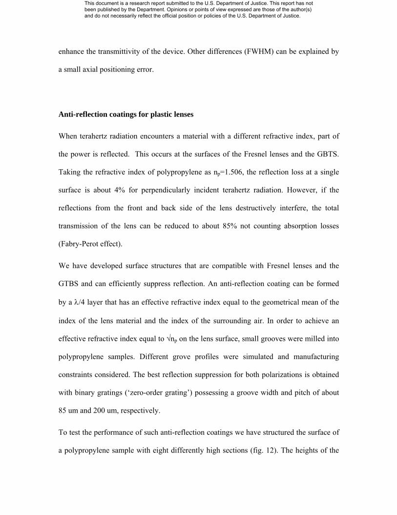
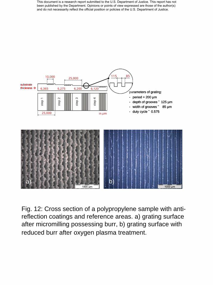
To test the performance of such anti-reflection coatings we have structured the surface of
a polypropylene sample with eight differently high sections (fig. 12). The heights of the
This document is a research report submitted to the U.S. Department of Justice. This report has not been published by the Department. Opinions or points of view expressed are those of the author(s) and do not necessarily reflect the official position or policies of the U.S. Department of Justice.
sections were chosen thus the Fabry-Perot filtering reaches its maximum and minimum
when no anti-reflection coating is applied.
The grooves were cut using ultraprecision micromilling and the adjacent flat reference
areas were prepared with a flycutting spindle, which leads to a very smooth surface finish
(RMS <10 nm).
Measurements of the transmitted power through the sample qualitatively confirmed the
impact of the anti-reflection coating as maximum and minimum transmissivity from
reference areas get reduced or enhanced, respectively. However, more investigation is
required to minimize measurement uncertainties in the analysis.
THz Microbolometer characterization and system integration
Honeywell, Inc. (subcontractor) delivered three different microbolometers used as THz
detector modules, which differed mainly with respect to internal electrical amplifier gain,
antenna bandwidth, and an anti-reflection coated window of their vacuum chambers. The
THz500-40G microbolometer is a single pixel detector, but the basic design can be scaled
to larger two dimensional arrays.
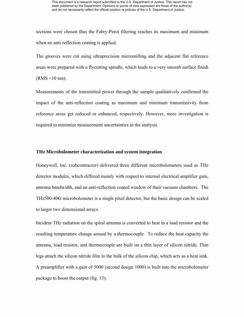
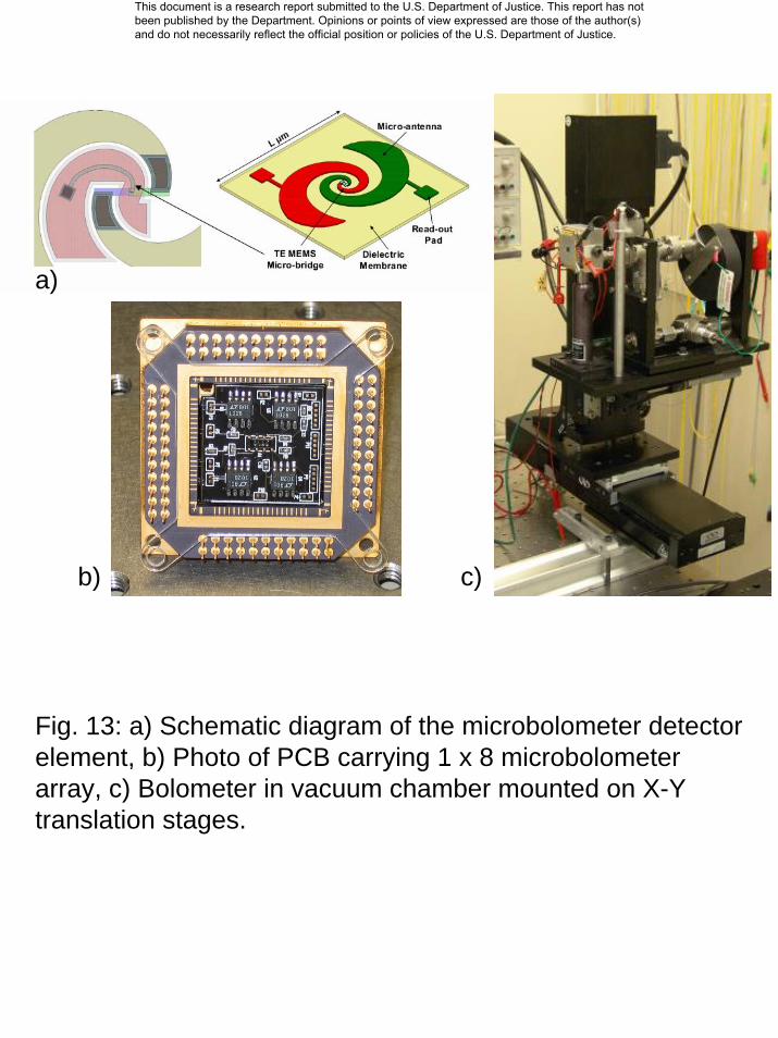
Incident THz radiation on the spiral antenna is converted to heat in a load resistor and the
resulting temperature change sensed by a thermocouple. To reduce the heat capacity the
antenna, load resistor, and thermocouple are built on a thin layer of silicon nitride. Thin
legs attach the silicon nitride film to the bulk of the silicon chip, which acts as a heat sink.
A preamplifier with a gain of 5000 (second design 1000) is built into the microbolometer
package to boost the output (fig. 13).
This document is a research report submitted to the U.S. Department of Justice. This report has not been published by the Department. Opinions or points of view expressed are those of the author(s) and do not necessarily reflect the official position or policies of the U.S. Department of Justice.
Basic electrical and optical parameters (responsivity, noise equivalent power, time
constant, linearity, frequency response) characterizing the microbolometer were
experimentally determined. Responsivity measurements with a thermal source (low
temperature furnace with a blackbody load) confirmed that the bolometer output is
proportional to the temperature of the load. A second measurement approach, based on a
much more intense narrow-band radiation source (VDI THz source), eliminated the need
to know the precise passband of the bolometer. But both measurements indicated a noise
equivalent power (NEP) of about 1 nW / sqrt(Hz). By comparison, the calculated NEP
based on the thermal properties of the microbolometer materials is 7.4 pW / sqrt(Hz), a
factor of more than 100 lower. However, the calculated NEP does not take into account
how efficiently terahertz radiation couples to the antenna and absorber. We believe that a
poor coupling efficiency of the incident beam into the detector structure is the main
reason that causes the NEP to be larger than expected. However, with an AR coated
window of the vacuum chamber an about five times better NEP was achieved and likely
further improvement is possible by redesigning PCB that holds the bolometer as it
impacts the characteristics of the spiral antenna.
The time constant of the bolometer response was measured by intensity switching the
THz source. Up to a switching frequency of 700 Hz the recorded output voltage stayed
flat indicating a time constant of 0.16 ms, which is comfortably short enough for video
rate imaging. In fact, it may also be possible to improve the bolometer NEP by reducing
the thermal conductance of the link to the heat sink, which would simultaneously increase
the time constant.
This document is a research report submitted to the U.S. Department of Justice. This report has not been published by the Department. Opinions or points of view expressed are those of the author(s) and do not necessarily reflect the official position or policies of the U.S. Department of Justice.
The bolometer passband showed some variations across the frequency interval from 610
GHz to 650 GHz. The membrane carrying the bolometer absorber is suspended over a
cavity in the silicon chip that is about one wavelength deep. This can induce resonance
effects that change the tuning of the spiral antenna on the absorber. There may be
additional resonance effects from reflections off the front of the bolometer chip and the
silicon vacuum window.
THz testbed setup
We built up a testbed that allows us to test and characterize the terahertz imager and its
components over distances as large as about 6 m (limited by lab space). The main parts of
the testbed are terahertz sources, computer controlled mechanical stages for detector
positioning, adjustable lens stands, a customized thermopile camera, a pyroelectric
camera, signal processing electronics, computer controlled data recording, and
adjustment tools.
Conclusion
In the project we could successfully develop and demonstrate passive components needed
for compact THz imagers. Both refractive optics based on Fresnel lenses and reflective
optics based on a Cassegrain objective were simulated, manufactured, lab tested, and
characterized. We could experimentally confirm that both designs approach well the
theoretical limit for best performance in terms of spatial resolution and have sufficient
performance to be used in THz imagers. A Gaussian-to-tophat beam shaper was
developed for homogenous illumination of the FOV. Simulations and experimental data
This document is a research report submitted to the U.S. Department of Justice. This report has not been published by the Department. Opinions or points of view expressed are those of the author(s) and do not necessarily reflect the official position or policies of the U.S. Department of Justice.
of recorded intensity distributions fit well. During all phases of the component
development, we have gained very valuable experience, not only by determining
performance limits from THz optics, but also by exploring their manufacturing
feasibility. Technical challenges during component prototyping were finally overcome by
innovative solutions.
We have characterized and integrated into the imager optics a THz detector based on
microbolometer technology that was designed by our subcontractor Honeywell, Inc. The
measured bolometer performance was significantly weaker than expected and not suitable
for THz imaging under real, or lab conditions. The main reasons for the low coupling
efficiency between the bolometer antenna and the THz optics were identified, but for
improvement a re-design of the bolometer hardware is necessary.
We have integrated and characterized in our testbed a THz source from Virginia Diodes,
Inc. While its performance is within specification, its output power was known to be too
low for imaging experiments at video rate. However, during the project period no other
source with more suitable parameters was commercially available as the originally
planned source vendor failed for technical reasons to provide an alternative solution.
The experience gained through out the project appears to be essential in the next design
phase for handheld THz imagers. Although a final product solution will require more
years of development, our results indicate that its availability will become a reality in the
near future. While we could show that THz imaging optics can be designed with
sufficient performance, source and detector technology have to be significantly advanced
before a product development can start.
This document is a research report submitted to the U.S. Department of Justice. This report has not been published by the Department. Opinions or points of view expressed are those of the author(s) and do not necessarily reflect the official position or policies of the U.S. Department of Justice.
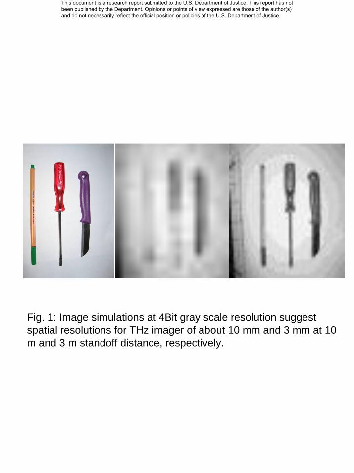
Fig. 1: Image simulations at 4Bit gray scale resolution suggest spatial resolutions for THz imager of about 10 mm and 3 mm at 10m and 3 m standoff distance, respectively.
This document is a research report submitted to the U.S. Department of Justice. This report has not been published by the Department. Opinions or points of view expressed are those of the author(s) and do not necessarily reflect the official position or policies of the U.S. Department of Justice.
0 50 100 150 200 250
FWHM ~ 550 µm
b)
a)
c)
Fig.2: a) Illumination of Fresnel optics with THz source from 3 m distance, b) measured diffraction spot with small aperture detector (step size 50 µm), c) thermopile image of diffraction spot in focal plane.
This document is a research report submitted to the U.S. Department of Justice. This report has not been published by the Department. Opinions or points of view expressed are those of the author(s) and do not necessarily reflect the official position or policies of the U.S. Department of Justice.

a)
Fig. 3: a) Side view of the imager optics, b) optics set for 3m imaging, c) secondary mirror moved 23.2 mm closer to primary mirror for 10m imaging.
b) c)
23.2 mm
This document is a research report submitted to the U.S. Department of Justice. This report has not been published by the Department. Opinions or points of view expressed are those of the author(s) and do not necessarily reflect the official position or policies of the U.S. Department of Justice.
a)
b)
c)
a)
b)
c)
Fig. 4: Diffraction image analysis. a) object target, simulated images for 3m imaging b) and 10m imaging c).
This document is a research report submitted to the U.S. Department of Justice. This report has not been published by the Department. Opinions or points of view expressed are those of the author(s) and do not necessarily reflect the official position or policies of the U.S. Department of Justice.
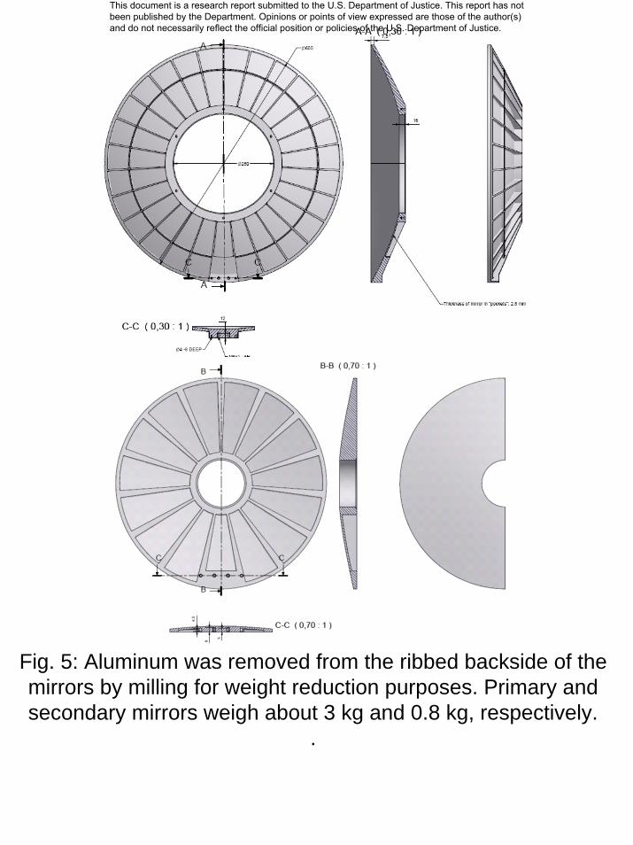
Fig. 5: Aluminum was removed from the ribbed backside of the mirrors by milling for weight reduction purposes. Primary and secondary mirrors weigh about 3 kg and 0.8 kg, respectively.
.
This document is a research report submitted to the U.S. Department of Justice. This report has not been published by the Department. Opinions or points of view expressed are those of the author(s) and do not necessarily reflect the official position or policies of the U.S. Department of Justice.
a)
b)
Fig. 6: a) Steel collar for form stabilization, b) Surfaces of primary mirror.
This document is a research report submitted to the U.S. Department of Justice. This report has not been published by the Department. Opinions or points of view expressed are those of the author(s) and do not necessarily reflect the official position or policies of the U.S. Department of Justice.
Test pattern Simulation
Fig. 7: Imaging of black-white pattern at 3m distance.
29 m
m o
bjec
t siz
e29
mm
obj
ect s
ize
6.6m
m im
age
size
Repaired optics
6.6m
m im
age
size
Optics with surface deformation
This document is a research report submitted to the U.S. Department of Justice. This report has not been published by the Department. Opinions or points of view expressed are those of the author(s) and do not necessarily reflect the official position or policies of the U.S. Department of Justice.
1 7
13 19 25 31 37
S1
S18
S35
020004000
6000
8000
10000
12000
14000
16000
Fig. 8: THz focal spot recorded with pyroelectric camera (100 µm pitch).
This document is a research report submitted to the U.S. Department of Justice. This report has not been published by the Department. Opinions or points of view expressed are those of the author(s) and do not necessarily reflect the official position or policies of the U.S. Department of Justice.
1 7
13 19 25 31 37
S1
S18
S35
0.00E+00
2.00E-04
4.00E-04
6.00E-04
8.00E-04
1.00E-03
1.20E-03
1.40E-03
1 7
13 19 25 31 37
S1
S18
S35
0.00E+00
2.00E-04
4.00E-04
6.00E-04
8.00E-04
1.00E-03
1.20E-03
1.40E-03
Fig. 9: Microbolometer scans of THz spot, a) 8x8 mm^2 (step size 200 µm), b) 2x2 mm^2 (step size 50 µm).
This document is a research report submitted to the U.S. Department of Justice. This report has not been published by the Department. Opinions or points of view expressed are those of the author(s) and do not necessarily reflect the official position or policies of the U.S. Department of Justice.
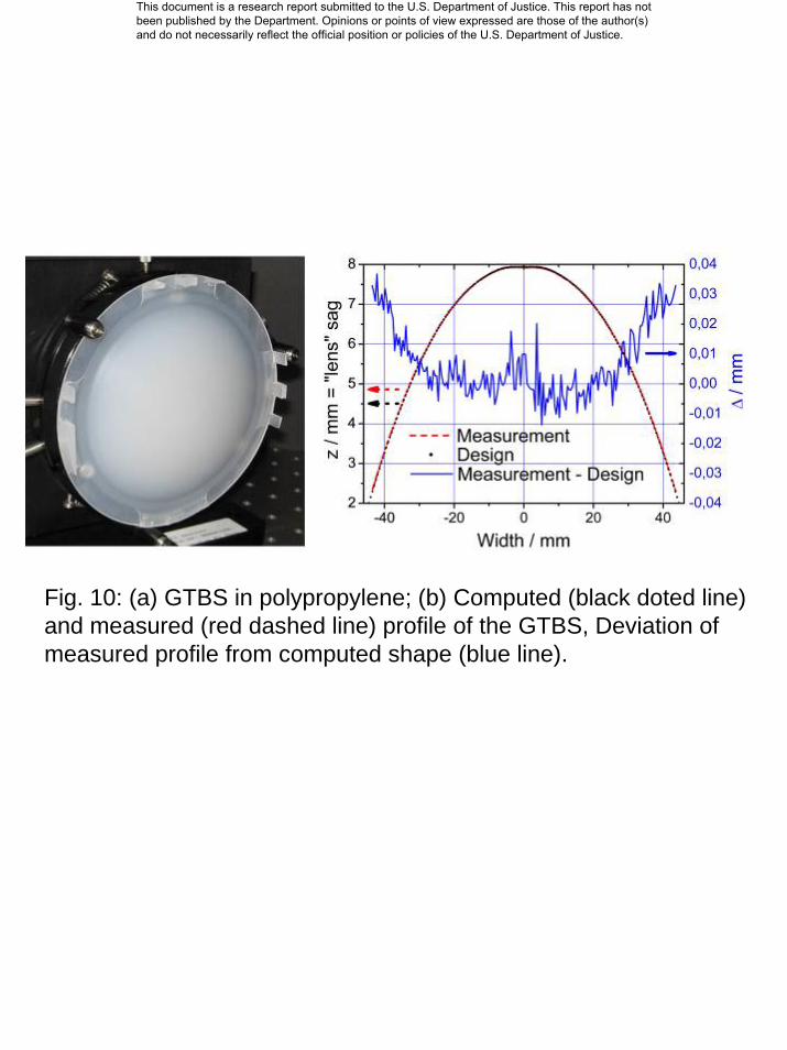
Fig. 10: (a) GTBS in polypropylene; (b) Computed (black doted line) and measured (red dashed line) profile of the GTBS, Deviation ofmeasured profile from computed shape (blue line).
This document is a research report submitted to the U.S. Department of Justice. This report has not been published by the Department. Opinions or points of view expressed are those of the author(s) and do not necessarily reflect the official position or policies of the U.S. Department of Justice.
a) b) c)
-10 -8 -6 -4 -2 0 2 4 6 8 100,0
0,2
0,4
0,6
0,8
1,0
Vertical Scan
I i/I 0
angle / deg
Measurement Gaussian Fit
-200 -150 -100 -50 0 50 100 150 2000,0
0,2
0,4
0,6
0,8
1,0
Vertical Scan
I i/I 0
width / mm
Measurement Simulation (ideal) Simulation (misaligned)
d) e)
Fig. 11: a) Measured intensity profile of THz source beam. b) Simulated intensity for misaligned GBTS, c) Measured intensity at 3 m distance, and corresponding vertical scans ( d) source, e) object plane).
This document is a research report submitted to the U.S. Department of Justice. This report has not been published by the Department. Opinions or points of view expressed are those of the author(s) and do not necessarily reflect the official position or policies of the U.S. Department of Justice.
substrate thickness
parameters of grating:- period = 200 µm- depth of grooves ˜ 125 µm- width of grooves ˜ 85 µm- duty cycle ˜ 0.575
substrate thickness
parameters of grating:- period = 200 µm- depth of grooves ˜ 125 µm- width of grooves ˜ 85 µm- duty cycle ˜ 0.575
a) b)a) b)
Fig. 12: Cross section of a polypropylene sample with anti-reflection coatings and reference areas. a) grating surface after micromilling possessing burr, b) grating surface with reduced burr after oxygen plasma treatment.
This document is a research report submitted to the U.S. Department of Justice. This report has not been published by the Department. Opinions or points of view expressed are those of the author(s) and do not necessarily reflect the official position or policies of the U.S. Department of Justice.
a)
b) c)
Fig. 13: a) Schematic diagram of the microbolometer detector element, b) Photo of PCB carrying 1 x 8 microbolometerarray, c) Bolometer in vacuum chamber mounted on X-Y translation stages.
This document is a research report submitted to the U.S. Department of Justice. This report has not been published by the Department. Opinions or points of view expressed are those of the author(s) and do not necessarily reflect the official position or policies of the U.S. Department of Justice.