Embed Size (px)
Citation preview
Standing Committee of Analysts
The Quantification of Asbestos in Soil (2017)
Methods for the Examination of Waters and Associated Materials

2
The quantification of asbestos in soils and associated materials (2017) Methods for the Examination of Waters and Associated Materials Whilst this booklet refers to equipment actually used, this does not endorse these products as being superior to other similar products. Equivalent equipment or innovative techniques may be available and it should be understood that resulting performance characteristics might differ when other products are used. It is left to users to evaluate these procedures in their own laboratories to ensure equivalent (or improved) performance. Only limited performance data are presented for this method.
3
Contents About this series .................................................................................................................. 5
Warning to users ................................................................................................................. 5
A The quantification of asbestos in soil and associated materials ........................ 6
Notes ..................................................................................................................................... 6
Glossary ................................................................................................................................. 8
Introduction .......................................................................................................................... 11
Other Information ................................................................................................................. 12
General comments on sampling, storage and subsampling ................................................ 12
General comments on analysis ............................................................................................ 12
Contract Review .................................................................................................................. 13
Hazards and safety precautions .......................................................................................... 13
References .......................................................................................................................... 14
A1 The quantification of asbestos in soils and associated materials .................... 16
A1.1 Scope ....................................................................................................................... 16
A1.2 Performance Characteristics of the Method ............................................................. 16
A1.3 Principle ................................................................................................................... 17
A1.3.1 Stage 1 Identification of asbestos according to HSG248 (2016 draft) ................. 17
A1.3.2 Stage 2 Gravimetric analysis ............................................................................... 17
A1.4 Interferences and Limitations ................................................................................... 19
A1.5 Sample handling ...................................................................................................... 20
A1.6 Reagents ................................................................................................................. 21
A1.7 Apparatus ................................................................................................................ 21
A1.7.1 Gravimetric .......................................................................................................... 21
A1.7.2 Free fibres ........................................................................................................... 21
A1.8 Analytical Procedure ................................................................................................ 23
A1.8.1 Stage 1 - Identification ......................................................................................... 23
A1.8.2 Stage 2 - Gravimetric analysis ............................................................................. 24
A1.8.3 Stage 3 - Preparation of samples for free fibre analysis using PCM/PLM ........... 25
Appendix 1 List of associated material types ............................................................... 32
Appendix 2 Comments re issues with the PCM dispersion method ............................. 33
Appendix 3 Quality Control ............................................................................................... 34
Appendix 4 ......................................................................................................................... 38
Address for correspondence ............................................................................................ 43
Members assisting with this booklet ............................................................................... 43
4
About this series Introduction This booklet is part of a series intended to provide authoritative guidance on methods of sampling and analysis for determining the quality of drinking water, ground water, river water and sea water, waste water and effluents as well as sewage sludges, sediments, soil (including contaminated soil) and biota. In addition, short reviews of the most important analytical techniques of interest to the water and sewage industries are included. Performance of methods Ideally, all methods should be fully validated with results from performance tests. These methods should be capable of establishing, within specified or pre-determined and acceptable limits of deviation and detection, whether or not any sample contains concentrations of parameters above those of interest. For a method to be considered fully evaluated, individual results encompassing at least ten degrees of freedom from at least three laboratories should be reported. The specifications of performance generally relate to maximum tolerable values for total error (random and systematic errors) systematic error (bias) total standard deviation and limit of detection. Often, full evaluation is not possible and only limited performance data may be available. An indication of the status of methods is normally shown at the front of these publications on whether the method has undergone full performance testing. In addition, good laboratory practice and analytical quality control are essential if satisfactory results are to be achieved. Standing Committee of Analysts The preparation of booklets within the series “Methods for the Examination of Waters and
Materials” and their continuing revision is the responsibility of the Standing Committee of Analysts. This committee was established in 1972 by the Department of the Environment and is now managed by the Environment Agency. At present, there are nine working groups, each responsible for one section or aspect of water quality analysis. They are 1 General principles of sampling and accuracy of results 2 Microbiological methods 3 Empirical, inorganic and physical methods, metals and metalloids 4 Solid substances 5 Organic impurities 6 Biological, biodegradability and inhibition methods 7 Radiochemical methods The actual methods and reviews are produced by smaller panels of experts in the appropriate field, in co-operation with the working group and main committee. The names of those members principally associated with this booklet are listed at the back of this booklet. Publication of new or revised booklets will be notified to the technical press. If users wish to receive copies or advance notice of forthcoming publications, or obtain details of the index of methods then contact the Secretary on the Agency’s internet web-site (www.gov.uk/environment-agency) or by post. Every effort is made to avoid errors appearing in the published text. If, however, any are found, please notify the Secretary. Rob Carter Secretary April 2017
_________________________________________________________________________ Warning to users
The analytical procedures described in this booklet should only be carried out under the proper supervision of competent, trained analysts in properly equipped laboratories. All possible safety precautions should be followed and appropriate regulatory requirements complied with. This should include compliance with the Control of Asbestos Regulations (2012),Health and Safety at Work etc Act 1974 and all regulations made under the Act, and the Control of Substances Hazardous to Health Regulations 2002 (SI 2002/2677). Where particular hazards exist in carrying out the procedures described in this booklet, then specific attention is noted.
Numerous publications are available giving practical details on first aid and laboratory safety. These should be consulted and be readily accessible to all analysts. Amongst such publications are; “Safe Practices in Chemical Laboratories” and “Hazards in the Chemical Laboratory”, 1992, produced by the Royal Society of Chemistry; “Guidelines for Microbiological Safety”, 1986, Portland Press, Colchester, produced by Member Societies of the Microbiological Consultative Committee; and “Safety Precautions, Notes for Guidance” produced by the Public Health Laboratory Service. Another useful publication is “Good Laboratory Practice” produced by the Department of Health.
5
A The quantification of asbestos in soil and associated materials
Notes The quantification of asbestos containing materials and dispersed asbestos fibres in soils or construction and demolition materials/products, and other associated materials, using a gravimetric method for ACM and fibre bundles, and dispersion and fibre counting for free fibres using Phase Contrast Microscopy.
Note 1 Prior to using this method, it is necessary to perform the identification of asbestos fibres, fibre bundles, or asbestos containing material (ACM) in the relevant sample using Polarised Light Microscopy as per the method described in the HSE guidance document HSG248: The analysts’ guide for sampling, analysis and clearance procedures (2016 draft). It is important to note that any commercial laboratory undertaking asbestos identification must be accredited to ISO 17025. Note 2 It is important to note that Regulation 21 of the Control of Asbestos Regulations 2012 requires that every employer who requests an external organisation to analyse a sample of any material to determine whether it contains asbestos must ensure that the organisation is accredited by an appropriate body* as competent to perform work in compliance with ISO 17025. Although not mandatory, it is strongly recommended that the organisation is accredited for quantification, as well as identification (which is mandatory). *The United Kingdom Accreditation Service (UKAS) is appointed as the sole National Accreditation Body (NAB) by the Accreditation Regulations, 2009, and operates under a Memorandum of Understanding (MoU) with the British Government. The MoU is an agreement between UKAS and the Secretary of State for Business Innovation and Skills (BIS) and conforms to the EU Legislative Framework – Regulation EC 765/2008. Note 3 Although not required for compliance with CAR 2012, there may be other requirements for the assessment of land contaminated by asbestos, imposed by regulators such as the Environment Agency (in England), Natural Resource Wales, the Scottish Environmental Protection Agency, the Northern Ireland Environment Agency, or Local Authorities with respect to the accreditation of laboratories for asbestos quantification analysis of soil and/or C&D materials. These regulatory bodies all have policies requiring that laboratories conducting analysis for regulatory purposes should have their methodologies accredited, including quantification of asbestos in soil and C&D materials (accreditation for identification is already mandatory). It is likely, therefore, that full-scope UKAS accreditation for the quantification of asbestos in soil and C&D materials will be a requirement of national environmental and local authority regulators alike in the preparation and submission of land quality assessment reports in accordance with BS10175, CLR11 and supporting technical guidance documentation, when used for regulatory purposes. Note 4 Prior to the implementation of this method, some laboratories offered a stand -alone visual screen to determine if asbestos containing material was present in the sample, but this would only cover pieces of ACM and fibre bundles, and would not include very small fragments or free dispersed fibres. UKAS state that ‘screening’ is now removed from UKAS accreditation schedules, as it is not an analytical method in itself, only part of the accredited identification process. Samples should be inspected under a stereomicroscope to determine the presence of potential ACM and fibres, and if detected, quantitative analysis
6

can then be performed according to this document, using gravimetric and fibre dispersion/counting as appropriate, to reliably quantify asbestos in the sample.
7
0BGlossary
Asbestos
Complex fibrous silicate minerals including: (a) asbestos actinolite, CAS No. 77536-66-4; (b) asbestos grunerite (amosite), CAS No. 12172-73-5; (c) asbestos anthophyllite, CAS No. 77536-67-5; (d) chrysotile, CAS No. 12001-29-5 or No. 132207-32-0; (e) crocidolite, CAS No. 12001-28-4; and (f) asbestos tremolite, CAS No. 77536-68-6 (CAR 2012)
Asbestos cement (AC) Asbestos-containing material (ACM) Asbestos containing soils (ACS) Aspect ratio Bulk sample Control limit
Cement material which is mainly a mixture of cement and chrysotile and which when in a dry state absorbs less than 30% water by weight (CAR 2012) Any discrete fragment of material that contains asbestos above trace levels (see definition of trace) ACOP definition: “Any mixture containing one or more of these fibrous silicates at more than trace amounts as defined in HSG248 Asbestos: The analysts’ guide… is within the definition. For any work covered by the Regulations, ‘asbestos’ also includes asbestos containing materials…” Soils, with construction and demolition materials/products and recycled aggregates, plus other associated materials, that contain individual fragments of ACM and/or isolated dispersed asbestos fibres at or above the detection limit of this method The ratio of the length of a fibre to its diameter. (1) An as-received sample containing soil, demolition and construction materials/products and/or associated materials (see Appendix 1) (2) Discrete fragments of materials such as spray coatings, pipe/thermal insulation, insulating boards/tiles, asbestos cement materials, other materials, dust and debris (HSG248 2016 draft) A concentration of asbestos fibres in the atmosphere when measured in accordance with the 1997 WHO recommended method, or by a method giving equivalent results to that method approved by the HSE of 0.1 f/cm3 of air (100,000 fibres/m3), ideally averaged over a continuous period of 4 hours.
8
Interferences MMMF PCM PLM Respirable fibres Short term exposure limit Trace*
Fibrous substances which, if present, may interfere with asbestos analysis. Some common fibres are (HSG248 para A3.14): natural organic fibres (such as cotton and hair), synthetic organic fibres (such as aramid, polyester and rayon), man-made mineral fibres (for example, mineral wool and glass fibre), and naturally occurring mineral 'fibres' (such as wollastonite and diatom fragments) and according to OSHA: Fibreglass; Anhydrite; Plant Fibres; Perlite Veins; Gypsum; Membrane Structures; Sponge Spicules; Microorganisms. This list refers to possible interferences with identification using PLM, and may be an issue using PCM. Man or Machine Made Mineral Fibres Phase Contrast Microscopy Polarised Light Microscopy Respirable fibres are defined as fibres of <3 µm diameter, longer than 5 µm and with aspect ratios of at least 3:1 that can be inhaled into the lower regions of the lung and are generally acknowledged to be most important predictor of hazard and risk for cancers of the lung. This is 0.6 fibres per cubic centimetre (f/ml) in the air measured over a ten-minute period. Any exposure which exceeds or is liable to exceed this is not sporadic and of low intensity. HSG248 (2016 draft) states: “It is recommended ‘asbestos not detected’ is reported when no asbestos fibre is found after careful searching of the sample under the stereo microscope for 10 minutes, and searching a minimum of two preparations mounted in suitable RI liquid at high magnification by PLM/PCM for a further 5 minutes. If, during the search of the two ‘pinch’ samples by PLM, < 3 fibres/fibre bundles are seen and identified as asbestos, the term ‘asbestos identified at the limit of detection’ may be used.’* Note that this applies to standard bulk samples, typically fragments of suspected ACMs, in which no fibres have been seen using the stereo microscope, or no asbestos fibres have been identified by PLM. In such cases, tweezers or probes should be used to take random sub-samples after the bulk sample has undergone suitable treatment (Appendix 2 HSG248, 2016 draft).
9
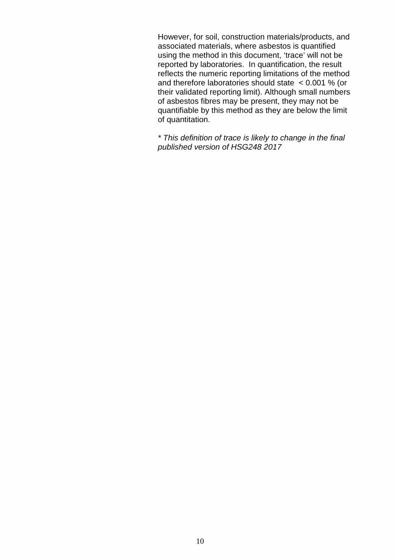
However, for soil, construction materials/products, and associated materials, where asbestos is quantified using the method in this document, ‘trace’ will not be reported by laboratories. In quantification, the result reflects the numeric reporting limitations of the method and therefore laboratories should state < 0.001 % (or their validated reporting limit). Although small numbers of asbestos fibres may be present, they may not be quantifiable by this method as they are below the limit of quantitation. * This definition of trace is likely to change in the final published version of HSG248 2017
10
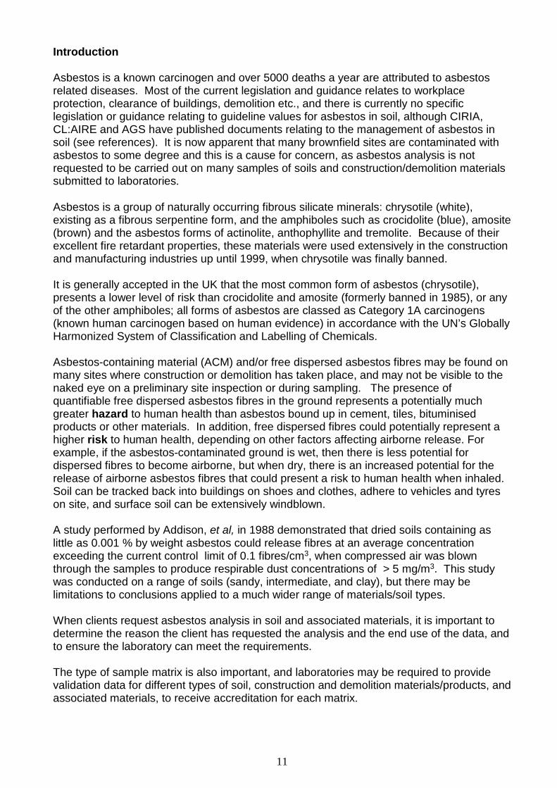
Introduction Asbestos is a known carcinogen and over 5000 deaths a year are attributed to asbestos related diseases. Most of the current legislation and guidance relates to workplace protection, clearance of buildings, demolition etc., and there is currently no specific legislation or guidance relating to guideline values for asbestos in soil, although CIRIA, CL:AIRE and AGS have published documents relating to the management of asbestos in soil (see references). It is now apparent that many brownfield sites are contaminated with asbestos to some degree and this is a cause for concern, as asbestos analysis is not requested to be carried out on many samples of soils and construction/demolition materials submitted to laboratories. Asbestos is a group of naturally occurring fibrous silicate minerals: chrysotile (white), existing as a fibrous serpentine form, and the amphiboles such as crocidolite (blue), amosite (brown) and the asbestos forms of actinolite, anthophyllite and tremolite. Because of their excellent fire retardant properties, these materials were used extensively in the construction and manufacturing industries up until 1999, when chrysotile was finally banned. It is generally accepted in the UK that the most common form of asbestos (chrysotile), presents a lower level of risk than crocidolite and amosite (formerly banned in 1985), or any of the other amphiboles; all forms of asbestos are classed as Category 1A carcinogens (known human carcinogen based on human evidence) in accordance with the UN’s Globally Harmonized System of Classification and Labelling of Chemicals. Asbestos-containing material (ACM) and/or free dispersed asbestos fibres may be found on many sites where construction or demolition has taken place, and may not be visible to the naked eye on a preliminary site inspection or during sampling. The presence of quantifiable free dispersed asbestos fibres in the ground represents a potentially much greater hazard to human health than asbestos bound up in cement, tiles, bituminised products or other materials. In addition, free dispersed fibres could potentially represent a higher risk to human health, depending on other factors affecting airborne release. For example, if the asbestos-contaminated ground is wet, then there is less potential for dispersed fibres to become airborne, but when dry, there is an increased potential for the release of airborne asbestos fibres that could present a risk to human health when inhaled. Soil can be tracked back into buildings on shoes and clothes, adhere to vehicles and tyres on site, and surface soil can be extensively windblown. A study performed by Addison, et al, in 1988 demonstrated that dried soils containing as little as 0.001 % by weight asbestos could release fibres at an average concentration exceeding the current control limit of 0.1 fibres/cm3, when compressed air was blown through the samples to produce respirable dust concentrations of > 5 mg/m3. This study was conducted on a range of soils (sandy, intermediate, and clay), but there may be limitations to conclusions applied to a much wider range of materials/soil types. When clients request asbestos analysis in soil and associated materials, it is important to determine the reason the client has requested the analysis and the end use of the data, and to ensure the laboratory can meet the requirements. The type of sample matrix is also important, and laboratories may be required to provide validation data for different types of soil, construction and demolition materials/products, and associated materials, to receive accreditation for each matrix.
11
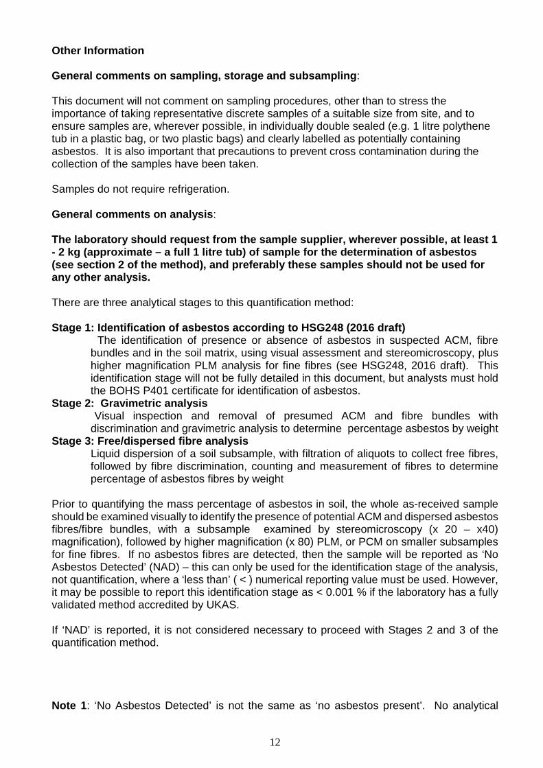
Other Information General comments on sampling, storage and subsampling: This document will not comment on sampling procedures, other than to stress the importance of taking representative discrete samples of a suitable size from site, and to ensure samples are, wherever possible, in individually double sealed (e.g. 1 litre polythene tub in a plastic bag, or two plastic bags) and clearly labelled as potentially containing asbestos. It is also important that precautions to prevent cross contamination during the collection of the samples have been taken. Samples do not require refrigeration. General comments on analysis: The laboratory should request from the sample supplier, wherever possible, at least 1 - 2 kg (approximate – a full 1 litre tub) of sample for the determination of asbestos (see section 2 of the method), and preferably these samples should not be used for any other analysis. There are three analytical stages to this quantification method: Stage 1: Identification of asbestos according to HSG248 (2016 draft) The identification of presence or absence of asbestos in suspected ACM, fibre
bundles and in the soil matrix, using visual assessment and stereomicroscopy, plus higher magnification PLM analysis for fine fibres (see HSG248, 2016 draft). This identification stage will not be fully detailed in this document, but analysts must hold the BOHS P401 certificate for identification of asbestos.
Stage 2: Gravimetric analysis Visual inspection and removal of presumed ACM and fibre bundles with
discrimination and gravimetric analysis to determine percentage asbestos by weight Stage 3: Free/dispersed fibre analysis
Liquid dispersion of a soil subsample, with filtration of aliquots to collect free fibres, followed by fibre discrimination, counting and measurement of fibres to determine percentage of asbestos fibres by weight
Prior to quantifying the mass percentage of asbestos in soil, the whole as-received sample should be examined visually to identify the presence of potential ACM and dispersed asbestos fibres/fibre bundles, with a subsample examined by stereomicroscopy (x 20 – x40) magnification), followed by higher magnification (x 80) PLM, or PCM on smaller subsamples for fine fibres. If no asbestos fibres are detected, then the sample will be reported as ‘No Asbestos Detected’ (NAD) – this can only be used for the identification stage of the analysis, not quantification, where a ‘less than’ ( < ) numerical reporting value must be used. However, it may be possible to report this identification stage as < 0.001 % if the laboratory has a fully validated method accredited by UKAS. If ‘NAD’ is reported, it is not considered necessary to proceed with Stages 2 and 3 of the quantification method. Note 1: ‘No Asbestos Detected’ is not the same as ‘no asbestos present’. No analytical
12
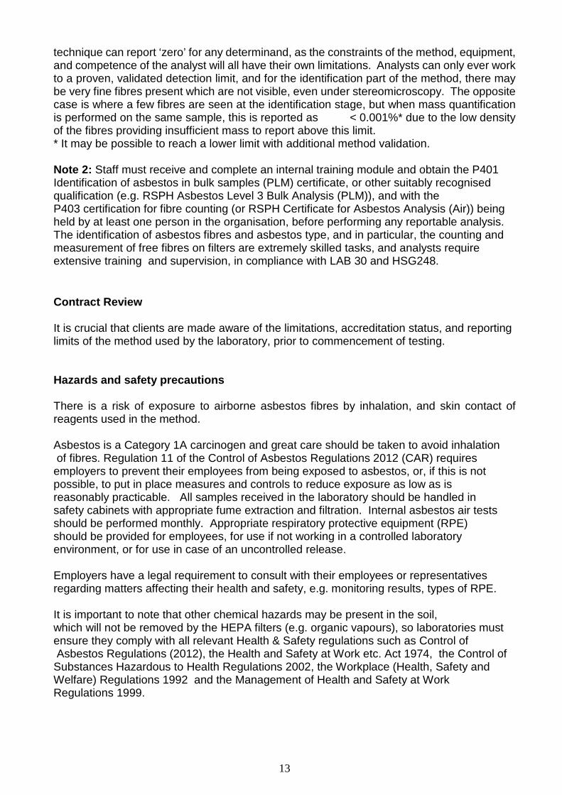
technique can report ‘zero’ for any determinand, as the constraints of the method, equipment, and competence of the analyst will all have their own limitations. Analysts can only ever work to a proven, validated detection limit, and for the identification part of the method, there may be very fine fibres present which are not visible, even under stereomicroscopy. The opposite case is where a few fibres are seen at the identification stage, but when mass quantification is performed on the same sample, this is reported as < 0.001%* due to the low density of the fibres providing insufficient mass to report above this limit. * It may be possible to reach a lower limit with additional method validation. Note 2: Staff must receive and complete an internal training module and obtain the P401 Identification of asbestos in bulk samples (PLM) certificate, or other suitably recognised qualification (e.g. RSPH Asbestos Level 3 Bulk Analysis (PLM)), and with the P403 certification for fibre counting (or RSPH Certificate for Asbestos Analysis (Air)) being held by at least one person in the organisation, before performing any reportable analysis. The identification of asbestos fibres and asbestos type, and in particular, the counting and measurement of free fibres on filters are extremely skilled tasks, and analysts require extensive training and supervision, in compliance with LAB 30 and HSG248. Contract Review It is crucial that clients are made aware of the limitations, accreditation status, and reporting limits of the method used by the laboratory, prior to commencement of testing. Hazards and safety precautions There is a risk of exposure to airborne asbestos fibres by inhalation, and skin contact of reagents used in the method. Asbestos is a Category 1A carcinogen and great care should be taken to avoid inhalation of fibres. Regulation 11 of the Control of Asbestos Regulations 2012 (CAR) requires employers to prevent their employees from being exposed to asbestos, or, if this is not possible, to put in place measures and controls to reduce exposure as low as is reasonably practicable. All samples received in the laboratory should be handled in safety cabinets with appropriate fume extraction and filtration. Internal asbestos air tests should be performed monthly. Appropriate respiratory protective equipment (RPE) should be provided for employees, for use if not working in a controlled laboratory environment, or for use in case of an uncontrolled release. Employers have a legal requirement to consult with their employees or representatives regarding matters affecting their health and safety, e.g. monitoring results, types of RPE. It is important to note that other chemical hazards may be present in the soil, which will not be removed by the HEPA filters (e.g. organic vapours), so laboratories must ensure they comply with all relevant Health & Safety regulations such as Control of Asbestos Regulations (2012), the Health and Safety at Work etc. Act 1974, the Control of Substances Hazardous to Health Regulations 2002, the Workplace (Health, Safety and Welfare) Regulations 1992 and the Management of Health and Safety at Work Regulations 1999.
13
References Addison, J., et al. 1996. HSE Contract Research Report No. 83/1996, Development and validation of an analytical method to determine the amount of asbestos in soils and loose aggregates. IOM, Edinburgh Addison, J., et al. 1988. Research Report TM/88/14, The release of dispersed asbestos fibres from soils. IOM, Edinburgh British Occupational Training Society (BOHS) Proficiency qualification P408: Analysis of asbestos in soils (pending publication in 2016) British Standards Institution BS 10175:2011+A1:2013, Investigation of potentially contaminated sites. Code of Practice (March 2011)
CL:AIRE, 2016 Control of Asbestos Regulations 2012 - Interpretation for Managing and Working with Asbestos in Soil and Construction & Demolition Materials: Industry Guidance. CL:AIRE, London. ISBN tba. Download at www.claire.co.uk/asbestos
CL:AIRE Joint Industry Working Group (JIWG) Asbestos in Soil Code of Practice (AiSCoP) (pending publication in 2016) www.claire.co.uk/asbestos CL:AIRE The Definition of Waste: Development Industry Code of Practice, Version 2, March 2011. ISBN 978 1 905046 23 2 www.claire.co.uk/asbestos
Environment Agency, 2004. Model Procedures for the Management of Land Contamination, CLR11
Health and Safety Executive (HSE), asbestos website www.hse.gov.uk/asbestos
Health and Safety Executive (HSE), HSG248 Asbestos: The Analyst’s Guide for Sampling, Analysis and Clearance Procedures, (2016 draft). Health and Safety Executive (HSE), HSG264: Asbestos: The Survey Guide. 2012 Health and Safety Executive (HSE), L143 2nd edition (2013) Managing and Working with Asbestos. Control of Asbestos Regulations 2012. Approved Code of Practice and Guidance.
Health and Safety Executive (HSE), L146 Consulting Workers on Health and Safety. Safety Representatives and Safety Committees Regulations 1977 (as amended) and Health and Safety (Consultation with Employees) Regulations 1996 (as amended). Approved Codes of Practice and guidance
Health and Safety Executive (HSE), L24 2nd Edition (2013) Workplace health, safety and welfare. Workplace (Health, Safety and Welfare) Regulations 1992 Approved Code of Practice and guidance
Health and Safety Executive (HSE), L5 6th edition (2013) Control of Substances Hazardous to Health. The Control of Substances Hazardous to Health Regulations 2002.
14
Approved Code of Practice and Guidance. Health and Safety Executive (HSE), MDHS 87 Guidance on the discrimination between fibre types in samples of airborne dust on filters using microscopy 1998 (to be replaced by Appendix 4 of HSG248 (2016 draft)) McCrone W.C. Asbestos Identification (Second Edition), The McCrone Research Institute, 1987. United Kingdom Accreditation Service (UKAS). LAB 30: Application of ISO/IEC17025 for Asbestos Sampling and Testing. See UKAS website for most recent version
15
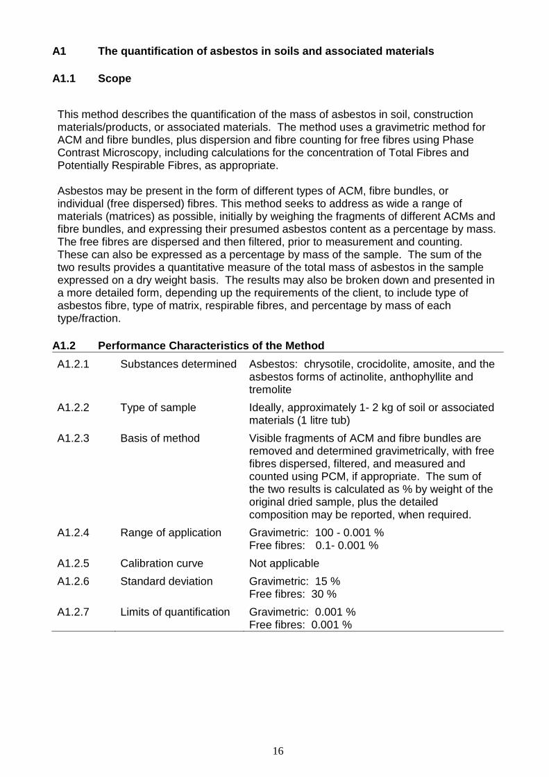
A1 The quantification of asbestos in soils and associated materials A1.1 Scope This method describes the quantification of the mass of asbestos in soil, construction materials/products, or associated materials. The method uses a gravimetric method for ACM and fibre bundles, plus dispersion and fibre counting for free fibres using Phase Contrast Microscopy, including calculations for the concentration of Total Fibres and Potentially Respirable Fibres, as appropriate.
Asbestos may be present in the form of different types of ACM, fibre bundles, or individual (free dispersed) fibres. This method seeks to address as wide a range of materials (matrices) as possible, initially by weighing the fragments of different ACMs and fibre bundles, and expressing their presumed asbestos content as a percentage by mass. The free fibres are dispersed and then filtered, prior to measurement and counting. These can also be expressed as a percentage by mass of the sample. The sum of the two results provides a quantitative measure of the total mass of asbestos in the sample expressed on a dry weight basis. The results may also be broken down and presented in a more detailed form, depending up the requirements of the client, to include type of asbestos fibre, type of matrix, respirable fibres, and percentage by mass of each type/fraction.
A1.2 Performance Characteristics of the Method A1.2.1 Substances determined Asbestos: chrysotile, crocidolite, amosite, and the
asbestos forms of actinolite, anthophyllite and tremolite
A1.2.2 Type of sample Ideally, approximately 1- 2 kg of soil or associated materials (1 litre tub)
A1.2.3 Basis of method Visible fragments of ACM and fibre bundles are removed and determined gravimetrically, with free fibres dispersed, filtered, and measured and counted using PCM, if appropriate. The sum of the two results is calculated as % by weight of the original dried sample, plus the detailed composition may be reported, when required.
A1.2.4 Range of application Gravimetric: 100 - 0.001 % Free fibres: 0.1- 0.001 %
A1.2.5 Calibration curve Not applicable A1.2.6 Standard deviation Gravimetric: 15 %
Free fibres: 30 % A1.2.7 Limits of quantification Gravimetric: 0.001 %
Free fibres: 0.001 %
16
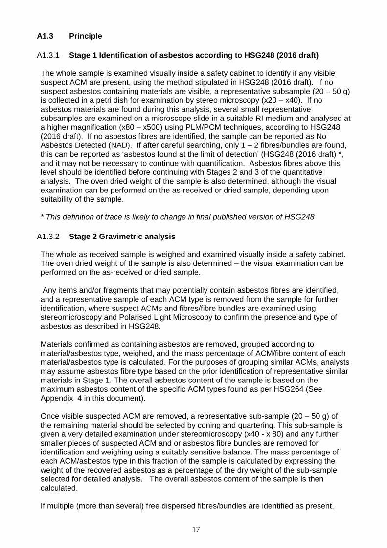
A1.3 Principle A1.3.1 Stage 1 Identification of asbestos according to HSG248 (2016 draft) The whole sample is examined visually inside a safety cabinet to identify if any visible suspect ACM are present, using the method stipulated in HSG248 (2016 draft). If no suspect asbestos containing materials are visible, a representative subsample (20 – 50 g) is collected in a petri dish for examination by stereo microscopy (x20 – x40). If no asbestos materials are found during this analysis, several small representative subsamples are examined on a microscope slide in a suitable RI medium and analysed at a higher magnification (x80 – x500) using PLM/PCM techniques, according to HSG248 (2016 draft). If no asbestos fibres are identified, the sample can be reported as No Asbestos Detected (NAD). If after careful searching, only 1 – 2 fibres/bundles are found, this can be reported as ‘asbestos found at the limit of detection’ (HSG248 (2016 draft) *, and it may not be necessary to continue with quantification. Asbestos fibres above this level should be identified before continuing with Stages 2 and 3 of the quantitative analysis. The oven dried weight of the sample is also determined, although the visual examination can be performed on the as-received or dried sample, depending upon suitability of the sample.
* This definition of trace is likely to change in final published version of HSG248
A1.3.2 Stage 2 Gravimetric analysis The whole as received sample is weighed and examined visually inside a safety cabinet. The oven dried weight of the sample is also determined – the visual examination can be performed on the as-received or dried sample. Any items and/or fragments that may potentially contain asbestos fibres are identified, and a representative sample of each ACM type is removed from the sample for further identification, where suspect ACMs and fibres/fibre bundles are examined using stereomicroscopy and Polarised Light Microscopy to confirm the presence and type of asbestos as described in HSG248. Materials confirmed as containing asbestos are removed, grouped according to material/asbestos type, weighed, and the mass percentage of ACM/fibre content of each material/asbestos type is calculated. For the purposes of grouping similar ACMs, analysts may assume asbestos fibre type based on the prior identification of representative similar materials in Stage 1. The overall asbestos content of the sample is based on the maximum asbestos content of the specific ACM types found as per HSG264 (See Appendix 4 in this document). Once visible suspected ACM are removed, a representative sub-sample (20 – 50 g) of the remaining material should be selected by coning and quartering. This sub-sample is given a very detailed examination under stereomicroscopy (x40 - x 80) and any further smaller pieces of suspected ACM and or asbestos fibre bundles are removed for identification and weighing using a suitably sensitive balance. The mass percentage of each ACM/asbestos type in this fraction of the sample is calculated by expressing the weight of the recovered asbestos as a percentage of the dry weight of the sub-sample selected for detailed analysis. The overall asbestos content of the sample is then calculated. If multiple (more than several) free dispersed fibres/bundles are identified as present,
17
then the Stage 3 dispersion/identification/counting method should be performed to ascertain the percentage of fibres, and/or the concentration of respirable fibres, present in the sample.
A1.3.3 Stage 3 Free/dispersed fibre analysis Following the gravimetric method, a representative subsample (1 – 5 g) of the residue is weighed into a conical flask, and water added in the ratio of 1:200 solid to liquid (volume dependent on sample type). The suspension is mixed vigorously for a minimum of 30 seconds to ensure complete dispersion, allowed to settle for 10 seconds, and then a known quantity is filtered through a cellulose-ester filter (0.8 – 1.2 microns). The filter is then placed onto a microscope slide, allowed to dry, and then cleared and fixed using the acetone/triacetin method described in HSG248, (2016 draft). The slides are then evaluated using PCM/polariser/red tint plate to discriminate and quantify the asbestos fibres. From the number and size of the potential asbestos fibres observed on the slides the mass percentage of asbestos in the sample is estimated. The relative contribution to the overall mass percentage from presumed amphibole and serpentine asbestos may also be estimated. The sum of both ACM/visible fibres and free fibres should also be reported as the % asbestos content in the original sample on a dry weight basis.
18
A1.4 Interferences and Limitations Asbestos is not uniformly distributed in soils, unlike some chemical contamination, and therefore using a sub-sample for detailed gravimetric analysis, and also for free dispersed fibre analysis, may decrease the representativeness of the data to the area of site from which the sample was collected. The use of maximum values for asbestos content (Appendix 4) in specific matrices may lead to an over estimate of the asbestos content in the sample. For PCM, it is only possible to exclude some non-asbestos fibres and the other fibres are presumed to be asbestos. When counting free fibres, if it is not possible to determine the fibre as non-asbestos, the fibre is presumed to be either chrysotile or amphibole based on the morphology of the fibre, although the use of PCM with polariser/analyser and red tint plate will limit this misidentification (HSG248 2016 draft). Fibres which are clearly identified as non-asbestos are not included in the count. PCM discrimination of asbestos fibres is generally limited to fibres with widths > 0.8 microns. Many asbestos fibres will have widths below this and will be presumed to be asbestos. An alternative to using PLM/PCM is the use of Scanning Electron Microscopy (SEM) or Transmission Electron Microscopy (TEM) with EDX. These methods provide a lower detection limit and avoid the possible identification issues, but are not as widely available. Clay matrices or oily samples may cause problems with the dispersion method (see Section 7.3.8).
19
A1.5 Sample handling All handling, opening of all containers, drying, and examination of samples for asbestos, should be conducted in a safety cabinet with appropriate extraction and HEPA filters. All staff must wear appropriate PPE. Care should be taken to avoid any risk of cross contamination, and the release of airborne fibres into the laboratory. This is particularly important once samples are dried, as dust is easily generated from these samples. It may be preferable to perform the initial examination on the as-received or dried sample (as in Stage 1), and results can then be corrected for the moisture content at a later stage, as appropriate. If the analysis is performed on the as-received sample, the sample must be dry enough for the analyst to be confident of detecting any asbestos that may be present, therefore very wet samples may require at least partial drying. Samples for quantification of asbestos should not be used for testing by other departments within the laboratory, as any removal of material will compromise the accuracy of the results. Therefore, the client should provide the laboratory with an individual asbestos sample whenever analysis for asbestos in soils, construction materials/products, and associated materials, is required. Clients should be encouraged to collect soil samples, typically a minimum of 1- 2 kg (wherever possible) in 1 litre tubs, or heavy duty polythene bags, and preferably individually double sealed (double bagged or a tub inside a bag) and labelled ‘ asbestos’. Samples containing larger particles, such as gravel, aggregates, or railway ballast, may require larger sample size. In this document, ‘whole sample’ refers to approximately 1- 2 kg of sample, and where larger bulk/ballast type samples are provided, these will require size reduction to provide a representative 1 kg sample suitable for analysis. No chemical preservation or refrigeration is required.
20
A1.6 Reagents A1.6.1 Acetone A1.6.2 Triacetin No reagents are required for the gravimetric section of the analysis. A1.7 Apparatus A1.7.1 Gravimetric A1.7.1.1 Balances capable of weighing to 2 and 5 decimal places, to achieve 0.001 % A1.7.1.2 Disposable gloves A1.7.1.3 Metal spatula A1.7.1.4 Safety cabinet fitted with high efficiency HEPA filtered extraction units The cabinet extractor units and face velocities are checked regularly in line with
current guidance (HSG248 2016 draft) to ensure the linear velocity is > 0.5 m/s and DOP tested every six months to check filter efficiency.
A1.7.1.5 Sample bags A1.7.1.6 Stereomicroscope A1.7.2 Free fibres A1.7.2.1 Balance capable of weighing to 2 decimal places A1.7.2.2 Analytical balance capable of weighing to 5 decimal places A1.7.2.3 Blunt nose forceps A1.7.2.4 Mixed cellulose-ester membrane filters, 25 mm diameter, pore size of 0.8 or 1.2 µm,
(blank tested) A1.7.2.5 Straight-sided filter apparatus A1.7.2.6 Filtration collar A1.7.2.7 Vacuum pump A1.7.2.8 Auto pipettes, various, including one capable of pipetting 0.25 ml A1.7.2.9 1 ml Pasteur pipette A1.7.2.10 Acetone hot block/vaporiser
21
A1.7.2.11 Microscope slides and coverslips – the slides should be 0.8 – 1.0 mm thick and
the coverslips should be 0.16 – 0.19 mm thick A1.7.2.12 5 ml Syringe A1.7.2.13 Conical flasks, various volumes up to 1000 ml
A1.7.2.14 Metal spatula
A1.7.2.15 Phase Contrast Microscope with Polariser/Analyser and Red Tint Plate (without
this addition, the fibre count could potentially be spuriously higher). The microscope should comply with the following specifications (HSG248 2016 draft):
a binocular stand with Köhler, or Köhler type illumination including a field iris. (The condenser (sub-stage assembly), objectives and eyepieces specified below must all be compatible with each other and with this stand.); a sub-stage assembly, incorporating an Abbe or an achromatic phase contrast, condenser in a centrable focusing mount, with phase annulus centring independent of the condenser centring mechanism; a built-in mechanical stage with slide clamps and x-y displacement; a low powered objective (e.g. X 10 or X 4 magnification), which is used for carrying out checks on the evenness of the dust deposit on the filter
A1.7.2.16 HSE Test Slide A1.7.2.17 Stage Micrometer slide
A1.7.2.18 G25 type Walton and Beckett Eyepiece Graticule, with an apparent diameter of
100 +/- 2 µm
A1.7.2.19 Tally Counter
A1.7.2.20 Coarse filters (for waste disposal)
A1.7.2.21 47 mm diameter 0.8 µm filters (for waste disposal)
A1.7.2.22 Oven for drying to a temperature between 30oC and 110oC
22
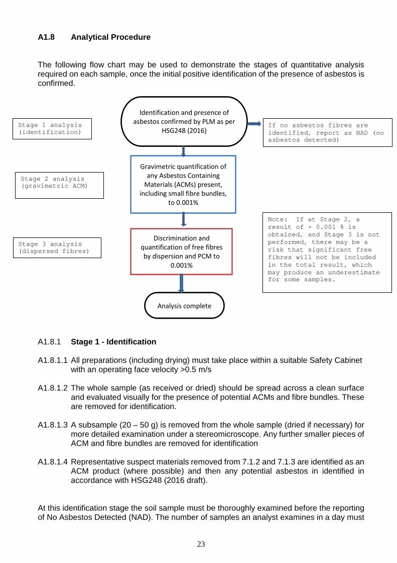
A1.8 Analytical Procedure The following flow chart may be used to demonstrate the stages of quantitative analysis required on each sample, once the initial positive identification of the presence of asbestos is confirmed. A1.8.1 Stage 1 - Identification A1.8.1.1 All preparations (including drying) must take place within a suitable Safety Cabinet
with an operating face velocity >0.5 m/s A1.8.1.2 The whole sample (as received or dried) should be spread across a clean surface
and evaluated visually for the presence of potential ACMs and fibre bundles. These are removed for identification.
A1.8.1.3 A subsample (20 – 50 g) is removed from the whole sample (dried if necessary) for
more detailed examination under a stereomicroscope. Any further smaller pieces of ACM and fibre bundles are removed for identification
A1.8.1.4 Representative suspect materials removed from 7.1.2 and 7.1.3 are identified as an
ACM product (where possible) and then any potential asbestos in identified in accordance with HSG248 (2016 draft).
At this identification stage the soil sample must be thoroughly examined before the reporting of No Asbestos Detected (NAD). The number of samples an analyst examines in a day must
If no asbestos fibres are identified, report as NAD (no asbestos detected)
Stage 1 analysis (identification)
Identification and presence of asbestos confirmed by PLM as per
HSG248 (2016)
Analysis complete
Gravimetric quantification of any Asbestos Containing
Materials (ACMs) present, including small fibre bundles,
to 0.001%
Discrimination and quantification of free fibres by dispersion and PCM to
0.001%
Stage 2 analysis (gravimetric ACM)
Stage 3 analysis (dispersed fibres)
Note: If at Stage 2, a result of > 0.001 % is obtained, and Stage 3 is not performed, there may be a risk that significant free fibres will not be included in the total result, which may produce an underestimate for some samples.
23
be scored and recorded in accordance with HSG248 (2016 draft) and LAB 30. If asbestos is identified by the method in HSG248 (2016 draft), then the visible fragments and fibre bundles/ fibres removed for ID must then be included in the quantification by gravimetric analysis, as in Section 7.2. A1.8.2 Stage 2 - Gravimetric analysis A1.8.2.1 The whole sample as-received is weighed. The whole sample may then be dried or
examined as-received. If the whole sample is not dried, a moisture content determination on a weighed subsample must be undertaken to allow the whole sample mass to be expressed as a dry weight. Drying temperatures in this method are not critical as asbestos is not volatile. Drying times are determined by the laboratory.
A1.8.2.2 The whole sample (as-received or dried) should be spread across a clean surface
and evaluated visually for the presence of potential ACMs and fibre bundles. These are all removed for weighing, ensuring as much soil and other debris is removed as is possible. This evaluation may be assisted by the removal or separation of large non ACM such as stone, brick or concrete. During this exercise the surface of such material must be examined for ACM and fibre bundles, and any suspected asbestos scraped off, where possible, to be included in the analysis.
Note: Any large material removed from the whole sample must be weighed, as this mass may be required for the calculations in the detailed gravimetric and the free fibre quantification methods. A1.8.2.3 The removed suspect material is examined using PLM in accordance with HSG248
(2016 draft). All identified ACM and asbestos fibre bundles (with soil/other debris removed) are placed in a pre-weighed Petri dish (one for each type of visually similar ACM and/or fibre bundles) and dried. Re-weigh the Petri dishes after drying.
Note: It may be advisable to photograph the materials, if appropriate. A1.8.2.4 For ACMs, the mass of the asbestos in each ACM is determined by identifying the
product type and assigning the appropriate correction factor (refer to Appendix 4). For fibre bundles, no correction factor is applied. The % of total asbestos in the whole sample at this stage is determined by summation of the different percentages for every ACM type in the formula below.
���
𝐴𝐴𝑆𝑆
× 100� × �𝐶𝐶
100��
Where
A = the dry weight of each type of ACM (g), as derived from 7.2.3 S = total dry sample weight (g) as derived from 7.2.1
C = the asbestos content of each ACM based on the maximum value given in HSG264 (reproduced in Appendix 4 of this document)
24
Note: Steps 7.2.1 – 7.2.3 may be performed at the same time as the identification process detailed in Section 7.1 Identification, to avoid double handling of the sample. A1.8.2.5 Detailed gravimetric analysis is usually undertaken with steps 7.2.1 – 7.2.4. At
step 7.2.2, any large material removed to allow a thorough visual assessment, is weighed (after drying if necessary).
A1.8.2.6 The remaining sample, after material removal (including large material previously
isolated, ACM’s and fibre bundles), is reduced by coning and quartering to obtain a representative subsample, which is typically 20 – 50 g. This is normally dried before detailed examination under stereomicroscopy (x 80), and may require disaggregation.
A1.8.2.7 It is possible to identify and handpick small fragments of ACM and fibre bundles that
were not identified during the initial examination of the bulk sample in step 7.2.2. The representative suspect material is examined in accordance with HSG248 (2016 draft).
A1.8.2.8 All identified ACM and asbestos fibre bundles are transferred to suitable containers
and weighed on a 5 place analytical balance. The mass of the asbestos in each ACM or fibre bundle type is determined in accordance with 7.2.4.
A1.8.2.9 Results for this stage of the analysis are calculated by expressing the weight of
any asbestos recovered as a percentage of the weight of the sub-sample selected for detailed analysis. 1 mg of asbestos recovered from 20 g of fines represents 0.005 %.
A1.8.2.10 If during detailed analysis of the sub-sample, asbestos fibres are identified, but
these are either too few and/or they are too fine to hand pick and weigh then these should be quantified using the fibre counting/sizing method by PCM.
A1.8.2.11 The % of the total asbestos in the subsample is determined by summation of
the different percentages for every ACM type in the formula below.
���𝐴𝐴𝑆𝑆
× 100� × �𝐶𝐶
100�� 𝑋𝑋 𝐶𝐶𝐶𝐶𝐶𝐶𝐶𝐶𝐶𝐶𝐶𝐶𝐶𝐶𝐶𝐶𝐶𝐶𝐶𝐶𝐶𝐶𝐶𝐶𝐶𝐶 𝑓𝑓𝐶𝐶𝐶𝐶𝐶𝐶𝐶𝐶𝐶𝐶
Where
A = the dry weight of each type of ACM (g) as derived from 7.2.7 S = total dry sub-sample weight (g) as derived from 7.2.6
C = the asbestos content of each ACM based on the maximum value given in HSG248 2016 draft, reproduced in Appendix 4 of this document
The concentration factor is derived from the mass (g) of dry material (stone, brick concrete etc.) from step 7.2.2 and dry ACM and asbestos bundles from step 7.2.3 which contributed to the mass of the bulk sample, but were removed prior to the preparation of the sub-sample.
A1.8.2.12 The total gravimetric concentration is finally derived (if required) by summation
of the two percentages obtained in steps 7.2.4 and 7.2.11 A1.8.3 Stage 3 - Preparation of samples for free fibre analysis using PCM/PLM
25
A1.8.3.1 Weigh between 1 and 5 g of the residual material from 7.2.6 into a suitably sized conical flask, and record the weight to 2 decimal places.
A1.8.3.2 Add water in a ratio 1:200 solid to liquid (depending upon the sample matrix). Note: For soils and made ground consisting of predominantly coarse grained materials, this ratio will be adequate, but with increasingly fine clay materials, a greater liquid to solid ratio may be necessary. A1.8.3.3 Vigorously agitate the sample for a minimum of 30 seconds until the sample is
completely dispersed. A1.8.3.4 Leave the sample to stand for 10 seconds to allow the denser material to settle. A1.8.3.5 Set up the filter assemblies with mixed cellulose-ester filters, 25 mm diameter with
a pore size of 0.8 or 1.2 µm, using blunt nose forceps. Ensure blank tested filters are used to eliminate background fibres.
A1.8.3.6 Label each slide with the appropriate sample identification. A1.8.3.7 Add approximately 5 ml of water to the filter to ensure even distribution of the aliquot
on the filter. A1.8.3.8 After the 10 seconds settling period, using a calibrated pipette, take a 1 ml aliquot
from the mixture, from approximately 3 cm below the surface, and deposit this into the water on the filter. The volume removed may need to be less than 1 ml, depending on the quantity of suspended matter. Filter this suspension of the sample in water under vacuum.
Where prepared slides are found to be occluded and uncountable (for example, from samples with a high clay content) the suspension should be diluted by taking a 10 ml aliquot after shaking from the original suspension and making up to 100 ml. This diluted sample should then be processed as the original after further shaking/standing. The solution should be diluted further, if required, until an acceptable slide can be prepared. The limit of detection/reported results should be corrected for the dilution.
(see Appendix 2 for examples) A1.8.3.9 Remove the filter from the filter assembly and place onto the labelled microscope
slide. A1.8.3.10 Allow the filters to dry, ensuring the filters do not curl, before clearing and fixing
using the acetone / triacetin method described in section 7.3.11. A1.8.3.11 Clearing and fixing microscope slides Acetone vapour is highly flammable and slightly toxic. Wear gloves for this stage to prevent acetone vapour coming into contact with skin A1.8.3.11.1 Ensure the acetone vaporiser is on, checking that it is at the correct
temperature.
26

A1.8.3.11.2 Position the filter on the microscope slide underneath the outlet of the acetone vaporiser and inject acetone slowly into the hot block so that the acetone emerges in a steady stream over the filter.
A1.8.3.11.3 Place the cleared filter onto the hot block for a few seconds to allow any excess
acetone to evaporate. A1.8.3.11.4 Place a drop or two of triacetin onto a clean coverslip using a micropipette or
other suitable dropper, invert the slide and lower the filter onto the coverslip. A1.8.3.11.5 Place the mounted slide onto the hot block until the triacetin has cleared, and
then evaluate the filter using phase contrast optical microscopy (PCM). A1.8.3.12 Microscope adjustment prior to counting and classification of fibres It is important to stress again the high level of skill and training required by the analyst when identifying, counting, and measuring fibres on the filters examined under the microscope. Extensive training and participation in internal QC and external PT schemes is required, with close supervision, before the analyst can perform analyses unaided. This should not be underestimated. The following sequence is taken from HSG248 (2016 draft) – other sequences can be used provided all the necessary adjustments and checks are made. A1.8.3.12.1 The microscope must be adjusted and used in accordance with the
manufacturer’s instructions and HSG248 (2016 draft), and the analyst must check its performance at the beginning of each counting session (or more frequently if any adjustments have been made):
A1.8.3.12.2 Place, centre and focus the working stage micrometer, preferably using bright-
field illumination. If necessary use the low-powered objective to help locate the 0-100 μm scale, then return to the X 40 objective;
A1.8.3.12.3 Check and re-adjust the field iris and condenser height at the working
magnification to obtain Kohler or Köhler type illumination.
A1.8.3.12.4 Check (and adjust if necessary) that the inter-ocular distance is correct for the user, the image has sharp focus in both oculars and that the Walton-Beckett graticule is also in sharp focus;
A1.8.3.12.5 Measure and record the diameter of the Walton Graticule against the stage micrometer - this should be 100 +/-2 µm – the measured diameter should be used in calculations.
A1.8.3.12.6 Remove the stage micrometer and replace it with the HSE test slide.
A1.8.3.12.7 Centre and focus the test slide using phase contrast microscopy, (if necessary use dark field illumination and a low-powered objective to help locate the two sets of parallel grooves (tramlines) in which the test grating is located, before inserting the X 40 phase objective);
27
A1.8.3.12.8 Check using the Bertrand lens (or eye-piece telescope) that the phase rings are concentric and centred. Adjust if necessary.
A1.8.3.12.9 Check and readjust the field iris and condenser height at the working
magnification to obtain Köhler or Köhler type illumination
A1.8.3.12.10 Record which of the seven bands on the test slide is just visible (lines only partly seen) by traversing from the most visible to the least visible;
A1.8.3.12.11 The lines of block 5 of an HSE mark II test slide must be visible, while only
parts of block 6 ridges may be visible and none of block 7 ridges should be visible at the working magnification. Mark III test slides issued with a red certificate require that block 4 must be visible while only parts of the block 5 ridges may be visible and none of the block 6 ridges should be visible.
A1.8.3.12.12 The focus and condenser focus will need readjustment before each filter is
evaluated.
A1.8.3.12.13 200 graticule areas on the slide must be counted, although counting can stop if the analyst reaches 100 fibres, provided at least 20 fields have been evaluated, regardless of the number of graticules counted.
Note 1: A maximum number of 12 slides per day per analyst is recommended, due to the difficulty in counting and sizing fibres over a long period, as stated in LAB 30. HSG248 2016 draft: ‘ The number of graticule areas examined in any 8 hour period by one analyst should not normally exceed 2400, the equivalent of 12 samples, if 200 graticule areas are examined on each (for air samples).’ Analysts are recommended to take a break at least after every third or fourth slide identified/counted in succession, and if long shifts are worked, additional quality assurance (QA) measures may be necessary. The length and frequency of the fibre identifying/counting sessions will depend on the microscopist, the type of samples and the laboratory conditions. The number of samples evaluated in a day also differs from microscopist to microscopist: typically, analysts may take 10-25 minutes to evaluate a sample with a sparse dust deposit, but longer for greater numbers of fields and more difficult samples.’
Note 2: If any of the slides are uncountable for any reason, for example if the analyst tried to clear the filter before it was fully dry, then extra aliquots should be taken from the mixture to replace the unusable slides. Note 3: If the slides are uncountable due to excessive particle loading, then a new set of slides should be prepared, using a higher dilution. A1.8.3.13 Adjustment of the microscope and preparation for fibre evaluation using
PCM/PLM analysis
A1.8.3.13.1 Place the slide to be evaluated onto the microscope stage, and scan the slide at x 10 magnification to check for even deposition across the slide. If not, or if the particulates cover > 1/8 of the slide, then the slide should be discarded. Fibres on the filter should be counted using at least x 500 magnification.
28
A1.8.3.13.2 Ensure all the appropriate information is recorded for the sample (mass of
sample, volume of mixture, diameter of graticule and the weight of all the subsamples used and materials removed).
A1.8.3.13.3 Graticule areas for counting must be chosen at random to avoid bias and to be
representative of the exposed filter area. Fields lying within 4 mm of the filter edge should not be counted. Fields should be rejected if a filter grid line obstructs all or part of the field of view, or if more than half of the field is obscured by large particles. If more than 10 % of fields are rejected, then the whole slide should be rejected (HSG248 2016 draft).
A1.8.3.13.4 Where possible, each fibre observed must be classified as amphibole,
serpentine, or non-asbestos by using a combination of the fibre morphology, extinction, and sign of elongation characteristics, as described in MDHS 87 (to be replaced by Appendix 4 in HSG248 2016 draft). This fibre discrimination method is inherent within this Blue Book method and so does not require separate UKAS accreditation, as samples are derived from soil samples, not air samples. Straight or gently curved fibres which cannot be confirmed as non-asbestos (e.g. because they are too fine) should be presumed to be amphibole asbestos, while curled fibres should be presumed to be chrysotile.
A1.8.3.13.5 If an asbestos, or presumed asbestos, fibre is deemed ‘countable’, the fibre
must be sized using the graticule, and the measurements recorded. Fibres should be counted regardless of their contact with other particles, and all suspected asbestos fibres should be counted.
A1.8.3.13.6 Fibre dimensions for each fibre should be recorded to the nearest 5 µm for
length, and 0.5 µm for diameter. Only those parts of the fibre which lie inside the graticule area should be counted. If one end of the fibre is in the field, but the other end is outside, record half the length of the fibre. Fibre dimension may be recorded directly onto a spreadsheet.
A1.8.3.13.7 Analysts should keep track of the number of fields counted using a tally counter.
A1.8.3.13.8 On completion of the sample, the total number of graticule areas evaluated
(normally 200) should be recorded.
For a full explanation of counting rules, and examples please see Appendix 5
A1.8.3.14 Calculation of results A1.8.3.14.1 Mass Percentage The overall mass percentage of asbestos is given by the formula:
�𝐴𝐴 𝑊𝑊 (∑𝑉𝑉𝜌𝜌𝐴𝐴 + ∑𝑉𝑉𝜌𝜌𝐶𝐶)
𝐶𝐶𝑎𝑎𝑎𝑎𝑆𝑆× 100� × 𝐹𝐹
Where: ρA = average density of amphibole fibres (3.3 x 10⁻⁶ µg µm-3) ρc = density of chrysotile (2.5 x 10⁻⁶ µg/µm3) V = volume of fibre (µm3)
29
W = volume of mixture (ml) A = effective area of filter (mm2) S = Weight of soil in suspension (µg) a = area of graticule (mm2) N = number of graticules evaluated q = Vol aliquot on filter (ml) F = Material removed correction factor The material removed correction factor (F) is calculated using the following equation:
𝐹𝐹 =(𝑇𝑇 − 𝑔𝑔)
𝑇𝑇
Where: T = total dry weight of sample g = mass of material removed from test portion of sample (not suitable for quantification analysis) The purpose of this correction factor is to adjust the result to take into account large non-asbestos items within the sample such as stones which were too large to be analysed by PCM and which would therefore bias the result. A1.8.3.14.2 Potentially respirable fibres (optional) To produce the result, each fibre counted during PCM/PLM identification and measurement is checked to see whether it conforms to the definition of a respirable fibre as defined in HSG248 2016 draft, that is, greater than 5 µm in length, narrower than 3 µm in width, and with an aspect ratio of greater than 3:1. The number of potentially respirable fibres is calculated by first calculating the number of fibres per ml of the mixture using the following equation:
𝐹𝐹𝐶𝐶𝐹𝐹𝐶𝐶𝐶𝐶𝐹𝐹 𝑝𝑝𝐶𝐶𝐶𝐶 𝑚𝑚𝑚𝑚 =𝑎𝑎 × 𝐹𝐹
𝑉𝑉 × 𝐶𝐶 × 𝐺𝐺
Where: N = the number of respirable fibres counted F= the filter area (mm2) V = the volume of the aliquot (ml) n = the number of graticules counted G = the graticule area (mm2) The number of fibres per ml of mixture is then converted to the number of fibres per gram of original sample using the following equation:
𝐹𝐹𝐶𝐶𝐹𝐹𝐶𝐶𝐶𝐶𝐹𝐹 𝑝𝑝𝐶𝐶𝐶𝐶 𝑔𝑔 = 𝐹𝐹𝐶𝐶𝐹𝐹𝐶𝐶𝐶𝐶𝐹𝐹 𝑝𝑝𝐶𝐶𝐶𝐶 𝑚𝑚𝑚𝑚 × �𝑉𝑉𝑆𝑆�
Where: V = the volume of the mixture (ml) S = the mass of the dried sample in the mixture (g) A1.8.3.15 Reporting all quantitative data
30
Reports may include the following information, with respect to each and all stages of the analysis, subject to customer contract review:
• Total dry mass of sample • Total mass % of material removed (if applicable) • Asbestos type (from PLM analysis) in each ACM type, if required • Total mass % of asbestos • Total mass % of amphibole asbestos • Total mass % of chrysotile asbestos • Total gravimetric (ACM) mass % • Total gravimetric (ACM) % of each ACM type • Total mass % of free fibres • Total mass % (or fibres/g) of respirable fibres, if required • Any anomalies or problems, e.g. clay or chrysotile clumping
Any other options should be requested and discussed at contract review:
• Moisture content • Mass or % of material analysed • Comments on degree of degradation (see Appendix 4) • Photographs
B WASTE DISPOSAL
B1 After examination, the remaining subsamples should be double bagged within the
safety cabinet.
B2 Residual subsamples should be stored in a controlled area and retained for a minimum of six months before controlled disposal.
B3 All waste samples, filter papers, slides, and Petri dishes should be placed in
disposal bags inside the cabinets. Waste water from the PCM analysis should be filtered and the filter placed in the disposal bag. The filtrate should be disposed of by the laboratory’s standard disposal route.
B4 All waste should be disposed of in a UN-approved red polythene bag, with the
correct UN black and white Class 9 label stating the correct shipping name and the UN number of the asbestos, e.g. UN2212 amphibole of UN2590 chrysotile (standard UN asbestos waste bags). This bag should be sealed and placed inside a UN-approved clear bag similarly marked.
B5 This bag should be transported to a suitable waste disposal site with the appropriate
documentation and disposed of as hazardous asbestos waste.
B6 When asbestos waste is removed from the laboratory, a hazardous waste consignment note must be completed by the laboratory, and the waste collected by a registered waste carrier with a copy of the hazardous waste consignment note retained by the laboratory. Slight differences in regulations may apply in Scotland, Wales and Northern Ireland.
31
Appendix 1 List of associated material types
Top soil - usually composed of sand, clay, loamy soil (Crushed) Rocks and soils: Naturally occurring (containing one or more of the following)
i. Rock ii. Clay iii. Sand iv. Gravel v. Sandstone vi. Limestone vii. Crushed stone viii. China clay ix. Construction stone x. Stone from demolition of buildings or structures xi. Slate xii. Sub-soil (mixtures of rock, gravel, sand, clay, soil) xiii. Silt xiv. Dredgings (sediments – river, lake, canal, estuary)
Above descriptions may include the following:
• Track/railway ballast • Recycled aggregate • Made ground
(Crushed) Ceramic or concrete materials (containing)
i. glass, including fritted enamel ii. ceramics, including bricks, bricks and mortar, tiles, clay ware, pottery, china and
refractories iii. concrete, including reinforced concrete, concrete blocks, breeze blocks and
aircrete blocks The above may include the following:
• Recycled aggregate • Made ground
Made ground – can be highly variable: naturally occurring rocks and soils and ceramic or concrete materials, containing – clay, sand and gravel with glass, ceramics, bricks and concrete.
32
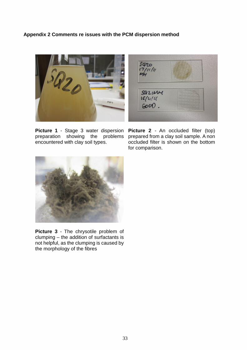
Appendix 2 Comments re issues with the PCM dispersion method
Picture 1 - Stage 3 water dispersion preparation showing the problems encountered with clay soil types.
Picture 2 - An occluded filter (top) prepared from a clay soil sample. A non occluded filter is shown on the bottom for comparison.
Picture 3 - The chrysotile problem of clumping – the addition of surfactants is not helpful, as the clumping is caused by the morphology of the fibres
33
Appendix 3 Quality Control QC schemes should comply with LAB 30 and HSG248 2016 draft – UKAS Asbestos Technical Bulletins may also provide guidance for analysis of asbestos in soils – refer to current UKAS publications. Analysts performing identification and quantitative analysis should participate and maintain a satisfactory performance in their internal laboratory QC scheme. Filters for fibre counting must be checked by performing blank counts prior to use. Checked batches of filters will have the assigned batch number and the initials of the analyst performing the blank count on the base of each box of 25 filters. Internal QC scheme The laboratory should retain a selection of asbestos containing materials, including a suitable range of soil types, matrices and concentrations, which, on a monthly basis, will be randomly issued to the laboratory for analysis by each authorised analyst for identification and quantification.
The results should fall within the margin of error calculated for the method during the method validation performed by the laboratory. In addition, the laboratory should establish a fibre classification and counting QC scheme based on the recommended internal QC scheme for asbestos air testing. The laboratory should retain a selection of slides at a range of concentrations and fibre types. External Proficiency Testing scheme The HSL operates a PT scheme for the identification and quantification of asbestos in soils, and as per LAB 30, the laboratory must participate, and maintain a satisfactory performance in this scheme in order to gain UKAS accreditation for this method. This scheme is known as the Asbestos in Soils Scheme (AISS), and covers both identification and quantification. Laboratories should also participate in the Asbestos in Materials Scheme (AIMS), which covers identification of asbestos in bulk materials, and is also operated by the HSL.
34
Appendix 4 Round Robin Date from AISS PT scheme Round 9 Asbestos in Soils Scheme (AISS) Report Round 9 February 2016 Asbestos in Soils Scheme Background This report covers Round 9 of the Asbestos in Soils Scheme (AISS). The scheme has two options; Qualitative and Quantitative. Thirteen laboratories participated in the Qualitative round and thirty eight laboratories participated in the Quantitative round Round 9 was open to laboratories outside the UK. Laboratory participation was as follows: 29 UK, 19 EU and 3 RoW. Samples Two samples were circulated as follows: Sample S017 – This sample was non-asbestos. The sample also contained sand, cement and plaster, plus blue nylon fibre. Sample S018 – This sample contained free anthophyllite fibres (loose fibres and in clumps) at 0.03% by weight. Each sample was individually made by mixing known weights of anthophyllite and soil. The sample also contained sand, cement and plaster. Information Submitted by Laboratories Laboratories used the HSL web-based PT data entry system to submit their results for this round. Results were submitted as asbestos type(s) present and for the Quantitative option, the % asbestos in ACMs, as loose fibres and the total % asbestos. Results Overview AISS Quantitative All thirty eight laboratories submitted qualitative results for both samples. Sample 017 - Thirty four laboratories correctly identified the sample as non-asbestos. Four laboratories falsely identified an asbestos type. Sample 018 - Thirty five laboratories correctly identified anthophyllite in this sample. One laboratory falsely identified amosite, one falsely identified actinolite, and one reported non-asbestos. Thirty six laboratories submitted quantitative results:
• 3 laboratories reported results within +/- 10% of the target value (0.027 – 0.033%) • 20 laboratories reported results within +/- 10% and 50% of the target value (0.015 –
0.026% and 0.034 – 0.045%) • 4 laboratories reported results within +/- 50% and 100% of the target value (0 –
0.014% and 0.046 – 0.060%) • 9 laboratories reported results greater 100% of the target value (>0.06%) • 2 laboratories did not submit quantitative results
35
AISS Qualitative Twelve laboratories submitted results for both samples
AISS Quantitative Scheme HSL PT Sample 017 Sample 018 Assigned Result: NAD Assigned Result: Anthophyllite (0.03%)
Laboratory Results Lab Result Result
7 No Asbestos Tremolite & Anthophyllite 0.068 766 No Asbestos Anthophyllite <0.00011* 801 No Asbestos Anthophyllite 1.28 803 No Asbestos Anthophyllite 0.04 807 No Asbestos Anthophyllite 0.103 869 No Asbestos Anthophyllite 0.07 885 No Asbestos Tremolite 0.003 1096 No Asbestos Anthophyllite 0.077 1161 No Asbestos Tremolite 0.04 1181 No Asbestos Anthophyllite 0.02 1258 No Asbestos Anthophyllite 0.052 1277 No Asbestos Tremolite 0.04 1294 No Asbestos Anthophyllite 0.042 1308 No Asbestos Tremolite 0.03 1329 No Asbestos Tremolite 0.035 1357 No Asbestos Anthophyllite 0.034 1365 No Asbestos Tremolite 0.35 1407 No Asbestos Anthophyllite 0.039 1450 No Asbestos Anthophyllite 0.003 1457 No Asbestos Anthophyllite 0.025 1495 No Asbestos Anthophyllite 0.07 1579 No Asbestos Anthophyllite NRS 1583 No Asbestos Anthophyllite 0.038 1633 No Asbestos Anthophyllite 0.023 1670 No Asbestos Tremolite 0.026 1675 No Asbestos Anthophyllite 0.02 1680 No Asbestos Anthophyllite 0.025 1711 No Asbestos Anthophyllite 0.042 1743 No Asbestos Anthophyllite 0.04 1753 No Asbestos Anthophyllite 0.03 1774 Anthophyllite Anthophyllite 0.02 1825 No Asbestos Anthophyllite 0.066 1843 No Asbestos Anthophyllite 0.07 1875 Chrysotile Anthophyllite 0.03 1923 No Asbestos Actinolite 0.02 1935 Crocidolite & Amosite Amosite 0.04 1942 Crocidolite No asbestos NRS
NRS No result submitted
36
Sample 017 – Eleven laboratories correctly identified the samples as non-asbestos. One laboratory falsely identified chrysotile. Sample 018 – Eleven laboratories correctly identified anthophyllite. One laboratory also identified crocidolite.
37
Appendix 4 Percentage of asbestos in different ACMs (taken from HSG264) Material % max Loose Insulation 100 Blanket, tape, cloth, rope and string 100 Paper, Felt* excludes any non-asbestos composite component 100 Millboard 97 Compressed Fibre Gaskets 90 Sprayed Coating 85 Thermal Insulation - Composite 85 Thermal Insulation - Caposil/Caposite 85 Loose fibrous asbestos debris* 85 Brake Pads, Clutch Plates 70 Cement 50 Insulating Board (excludes any non-asbestos composite component 40 Asbestos sheeting/board debris** 40 Cement - 'Asbestos Wood' 25 Thermoplastic Floor Tiles 25 Thermal Insulation - Sectional 15 Reinforced Plastic and Resin Composites 10 Bitumen Felt, DPC etc. 8 PVC Vinyl Floor Tiles 7 Textured Coatings 5
*Debris not readily identifiable as coatings or insulation **Debris not readily identifiable as AIB or any other board type Asbestos content is assumed as a worst case scenario, and maximum value of asbestos should be used in relevant calculations. Degree of Degradation or Weathering of Asbestos Containing Materials ‘Degraded’ at the outset means materials which are not generally intact. It applies to the current condition of the material (and not the original state) e.g. fragments of asbestos cement would be regarded as intact units. Also, ‘weathered’ asbestos cement is not regarded as degraded as it still retains its basic inherent integrity. For the purposes of definition of non-degraded and degraded, reference is made to the following degrees of degradation descriptors in the JIWG Work Category assessment Decision Support Tool:
1. Intact (very good condition ACM/ACM fragments 2. Weathered (slight degradation in ACM; material still retains its basic integrity) 3. Degraded (significant degradation in ACM; material has lost its basic integrity) 4. Disaggregated (dominated by loose fibrous material; extreme degradation in ACM
and/or free asbestos fibres/fibre bundles)
38
Appendix 5 Fibre Counting Rules Selecting fields for evaluation Graticule areas for counting must be chosen at random to avoid bias and to representative of the exposed filter area. Fields lying within 4 mm of the filter edge should not be counted. Fields should be rejected if a filter grid line obstructs all or part of the field of view, or if more than half of the field is obscured by large particles. To help prevent re-counting fibres, it is helpful to use the mechanical stage to move across the stage in straight lines. When evaluating each field, it may be helpful to examine each quarter graticule area individually, focusing up and down to ensure that all fibres are observed. Counting fibres A respirable fibre is as a fibre which is 5 µm or more in length, and has an aspect ratio of greater than 3:1. Fibres should be counted regardless of their contact with other particles. Where possible, each countable fibre observed must be classified as amphibole, chrysotile, or non-asbestos using the extinction and sign of elongation characteristics, as described in HSG248 2016 draft. Straight or gently curved fibres which cannot be confirmed as non-asbestos should be assumed to be amphibole asbestos, while curled fibres should be assumed to be chrysotile. If a fibre is deemed ‘countable’, and it is decided that the fibre should be classed as asbestos, then the fibre must be sized using the graticule and rotating stage, and the measurements entered directly onto the excel spreadsheet. Dimensions for each fibre should be recorded to the nearest 5 µm for length, and 0.5 µm for diameter. Analysts should keep track of the number of fields counted using a tally counter. Counting can stop if the analyst reaches 100 fibres, provided at least 20 fields have been evaluated, or on reaching 200 fibres, regardless of the number of graticules counted. On completion of the sample, the total number of graticule areas evaluated should be entered onto the spreadsheet. A fibre which is split should be sized according to the length of longest individual branch. The width of split fibres should be recorded as the narrowest width where all of the fibres are together (i.e. a place along the length of the fibre before it began to split), even if this point of measurement is outside of the graticule area. Chrysotile fibres are very difficult to measure, especially lengthways. They should be estimated using any straight sections of fibre available.
39
Individual branches of split fibres should not be counted individually as this will tend to greatly overestimate the mass of fibres present, split fibres should be assessed as one fibre. Very fine fibres, which are clearly finer than 0.5 µm, should still be recorded as 0.5 µm wide. Examples of measuring fibres and fibre counting rules are shown below: Fibre definitions 5 µm 3 µm
1 countable fibre Not countable (too short) 1 countable fibre (length measured along
curve)
1 countable fibre
Not countable (aspect ratio <3:1)
1 countable fibre (particle ignored)
Not countable (visible parts of fibre too short)
1 countable fibre, width assessed where all fibres are together
1 countable fibre (particle ignored)
40
Fibre definitions 5 µm 3 µm
2 countable fibres
No countable fibres distinguishable, and whole clump >5 µm wide
Measuring fibres
The graticule has two guides, one with increments of 5 µm and one with increments of 3 µm The 5 µm guide should be used to measure the length, and the 3µm guide used to measure the width. Two large fibres can be seen in this field. In
order to assess their size, they should be compared to the measurements on the graticule.
By rotating the stage, fibres can be lined up with the rulers, as in this diagram, making it easier to measure the dimensions.
41
Fibre definitions 5 µm 3 µm
After measuring the first fibre, the stage should be rotated again to measure the second fibre. This fibre does not lie directly on the guide, but by aligning it parallel to the guide the length can be estimated with reasonable accuracy.
Measure curved fibres by assessing the lengths of the straighter parts of the fibre
Measure the length of split fibres as the length of the longest part, and the width as the narrowest part of the fibre where all the branches are still attached to the main fibre, even is this point is outside of the graticule area, and record as half the length of the fibre.
Curved fibres passing right through the graticule should not be counted
Both the fibres in this field are less than 0.5 µm in width, and they should both be recorded as 0.5 µm, despite one fibre being obviously much finer than the other.
42
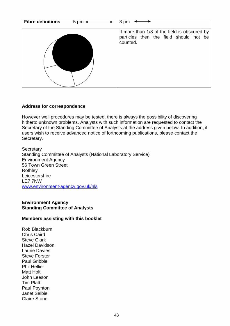
Fibre definitions 5 µm 3 µm
If more than 1/8 of the field is obscured by particles then the field should not be counted.
Address for correspondence However well procedures may be tested, there is always the possibility of discovering hitherto unknown problems. Analysts with such information are requested to contact the Secretary of the Standing Committee of Analysts at the address given below. In addition, if users wish to receive advanced notice of forthcoming publications, please contact the Secretary. Secretary Standing Committee of Analysts (National Laboratory Service) Environment Agency 56 Town Green Street Rothley Leicestershire LE7 7NW www.environment-agency.gov.uk/nls Environment Agency Standing Committee of Analysts Members assisting with this booklet Rob Blackburn Chris Caird Steve Clark Hazel Davidson Laurie Davies Steve Forster Paul Gribble Phil Hellier Matt Holt John Leeson Tim Platt Paul Poynton Janet Selbie Claire Stone
43

Rhodri Williams Aleksandra Witman David Wood Alan Willoughby Colette Willoughby
44