Embed Size (px)
Citation preview

Standby Power Systems Considerations
TVSFPE Chapter Meeting
Ken Cockerham
Nixon Power Services Company March 14, 2013
Basic Engine Generator Set
Rad
iato
r
Skid Base
Engine Alternator
Battery
Control Panel
Output Circuit
Breaker(s)
Air Intake Filter
Turbo Charger Exhaust Outlet
•Converts Mechanical
Energy into Electrical
Energy
•Engine Drives Alternator,
Resulting in Electrical
Power Output (AC)
• 1800 RPM Engine Speed
Gives 60 Hertz Electrical
Output
•Engine Power Capability is
Rated in Horsepower at
1800 RPM
Sub Base Fuel Tank
Automatic Transfer Switches
Automatic Transfer
Switch (ATS)
•Senses presence of
both/either power
sources
•Starts & Stops Genset
•Transfers Load from
One Source to the
Other
ATS-Generator
Control Wiring
ATS
Utility Source
Power to the
Load
The System and How it Works
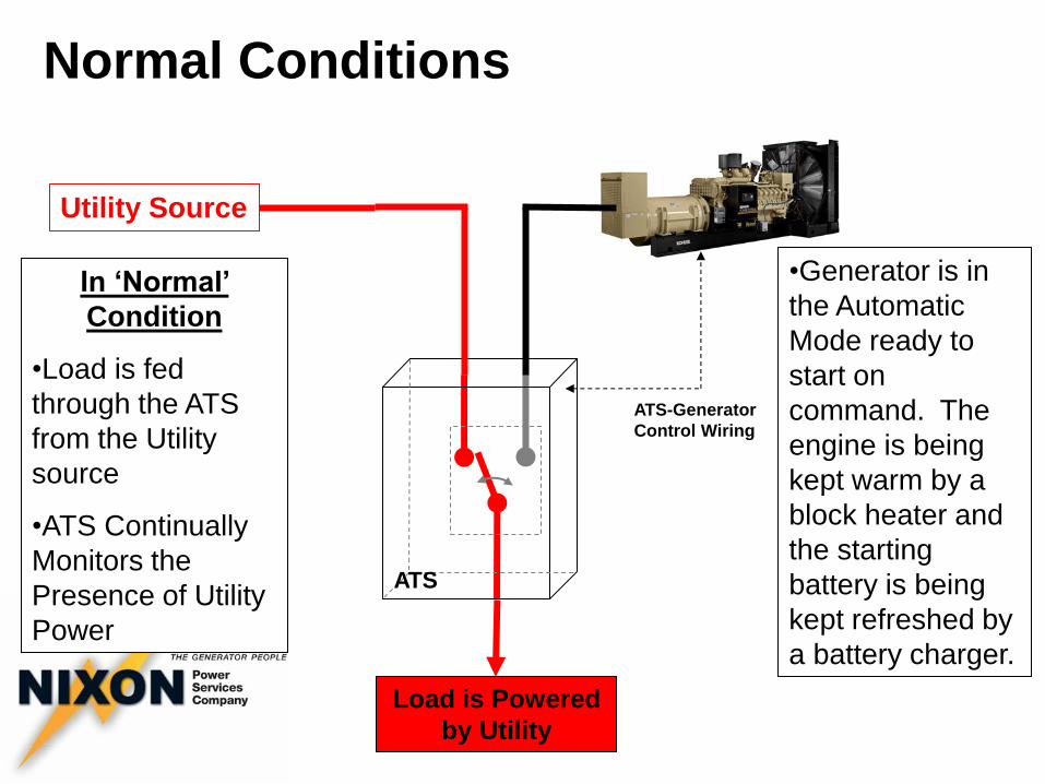
Normal Conditions
In ‘Normal’
Condition
•Load is fed
through the ATS
from the Utility
source
•ATS Continually
Monitors the
Presence of Utility
Power
•Generator is in
the Automatic
Mode ready to
start on
command. The
engine is being
kept warm by a
block heater and
the starting
battery is being
kept refreshed by
a battery charger.
ATS-Generator
Control Wiring
ATS
Utility Source
Load is Powered
by Utility
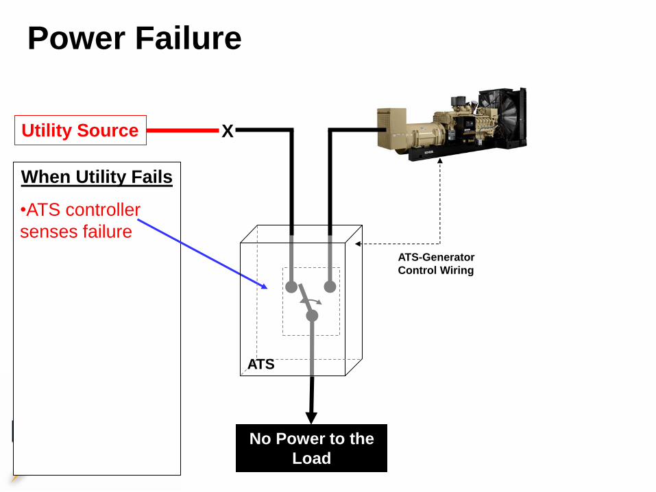
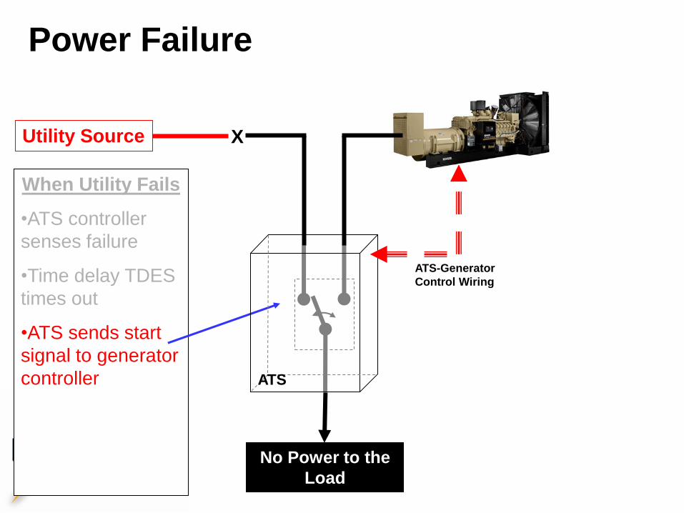
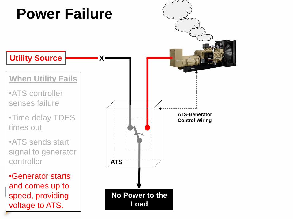
Power Failure
When Utility Fails
•ATS controller
senses failure
•Time delay TDES
times out
•ATS sends start
signal to generator
controller
•Generator starts
and comes up to
speed, providing
voltage to ATS.
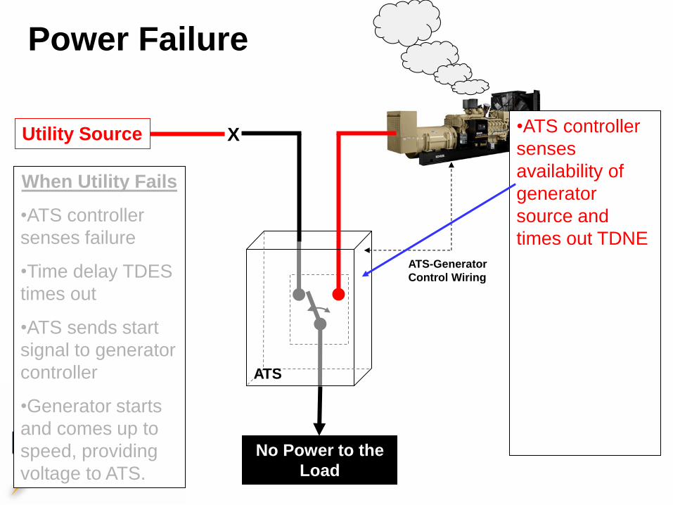
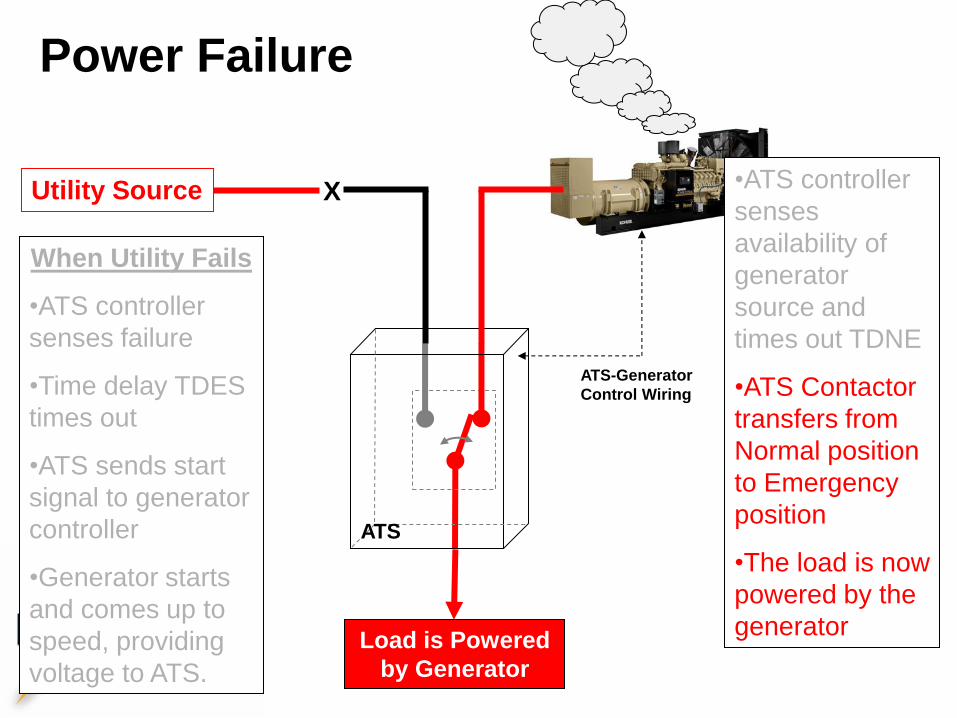
•ATS controller
senses
availability of
generator
source and
times out TDNE
•ATS Contactor
transfers from
Normal position
to Emergency
position
•The load is now
powered by the
generator
ATS-Generator
Control Wiring
ATS
Utility Source
No Power to the
Load
X
•ATS controller
senses
availability of
generator
source and
times out TDNE
•ATS Contactor
transfers from
Normal position
to Emergency
position
•The load is now
powered by the
generator
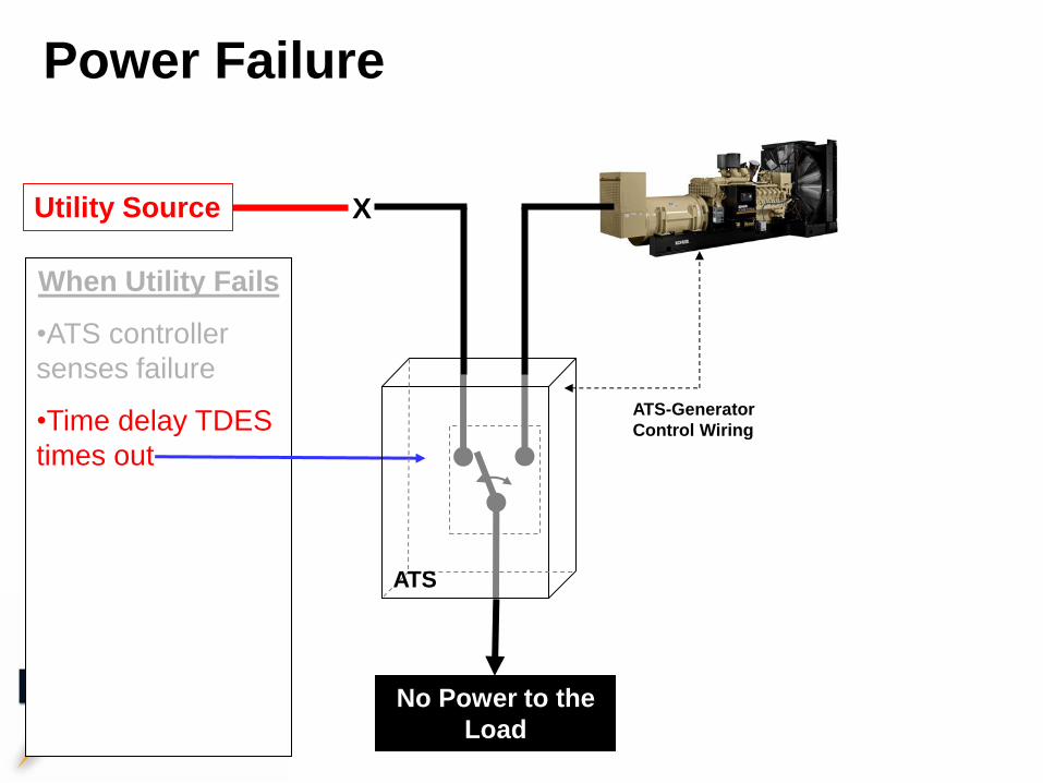
Power Failure
When Utility Fails
•ATS controller
senses failure
•Time delay TDES
times out
•ATS sends start
signal to generator
controller
•Generator starts
and comes up to
speed, providing
voltage to ATS.
ATS-Generator
Control Wiring
ATS
Utility Source
No Power to the
Load
X
•ATS controller
senses
availability of
generator
source and
times out TDNE
•ATS Contactor
transfers from
Normal position
to Emergency
position
•The load is now
powered by the
generator
Power Failure
When Utility Fails
•ATS controller
senses failure
•Time delay TDES
times out
•ATS sends start
signal to generator
controller
•Generator starts
and comes up to
speed, providing
voltage to ATS.
X
ATS-Generator
Control Wiring
ATS
Utility Source
No Power to the
Load
•ATS controller
senses
availability of
generator
source and
times out TDNE
•ATS Contactor
transfers from
Normal position
to Emergency
position
•The load is now
powered by the
generator
Power Failure
When Utility Fails
•ATS controller
senses failure
•Time delay TDES
times out
•ATS sends start
signal to generator
controller
•Generator starts
and comes up to
speed, providing
voltage to ATS.
ATS-Generator
Control Wiring
ATS
Utility Source
No Power to the
Load
X
Power Failure
When Utility Fails
•ATS controller
senses failure
•Time delay TDES
times out
•ATS sends start
signal to generator
controller
•Generator starts
and comes up to
speed, providing
voltage to ATS.
•ATS controller
senses
availability of
generator
source and
times out TDNE
•ATS Contactor
transfers from
Normal position
to Emergency
position
•The load is now
powered by the
generator
ATS-Generator
Control Wiring
ATS
Utility Source X
Load is Powered
by Generator
•The load is now
powered by the
utility
•Time delay TDES
times out
• ATS sends
shutdown signal to
generator controller.
Engine stays
running in cooldown
mode
•Time delay TDEC
times out
•The engine stops
and the generator is
ready for the next
outage
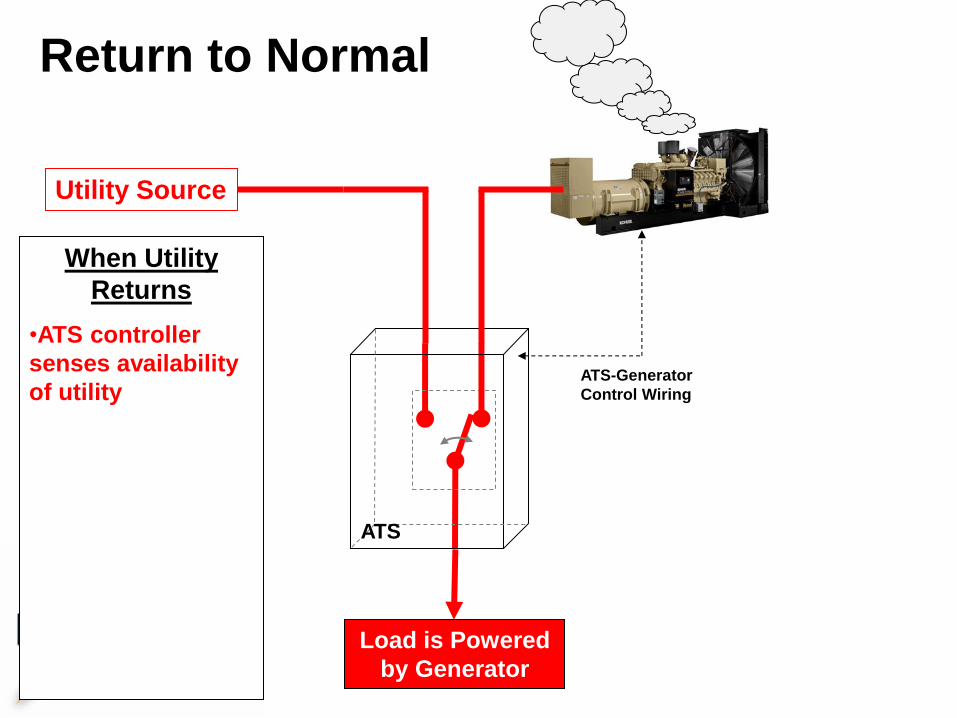
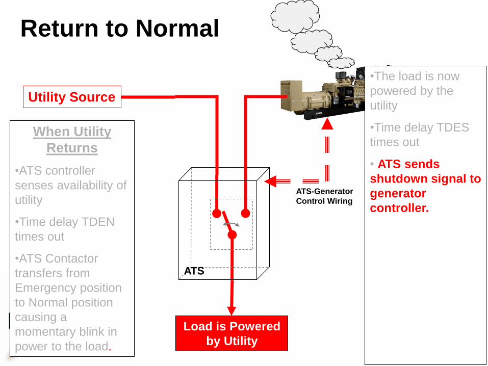
Return to Normal
When Utility
Returns
•ATS controller
senses availability
of utility
•Time delay TDEN
times out
•ATS Contactor
transfers from
Emergency position
to Normal position
causing a
momentary blink in
power to the load.
ATS-Generator
Control Wiring
ATS
Utility Source
Load is Powered
by Generator
•The load is now
powered by the
utility
•Time delay TDES
times out
• ATS sends
shutdown signal to
generator controller.
Engine stays
running in cooldown
mode
•Time delay TDEC
times out
•The engine stops
and the generator is
ready for the next
outage
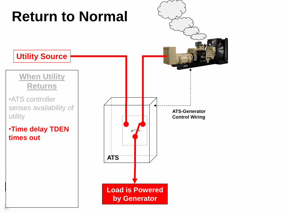
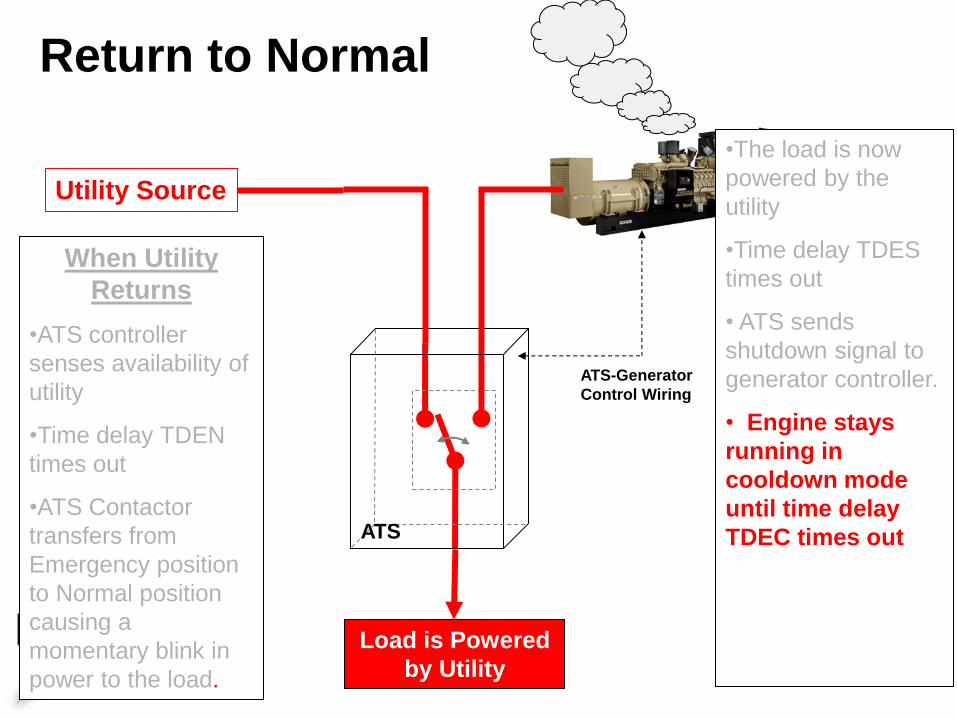
Return to Normal
When Utility
Returns
•ATS controller
senses availability of
utility
•Time delay TDEN
times out
•ATS Contactor
transfers from
Emergency position
to Normal position
causing a
momentary blink in
power to the load.
ATS-Generator
Control Wiring
ATS
Utility Source
Load is Powered
by Generator
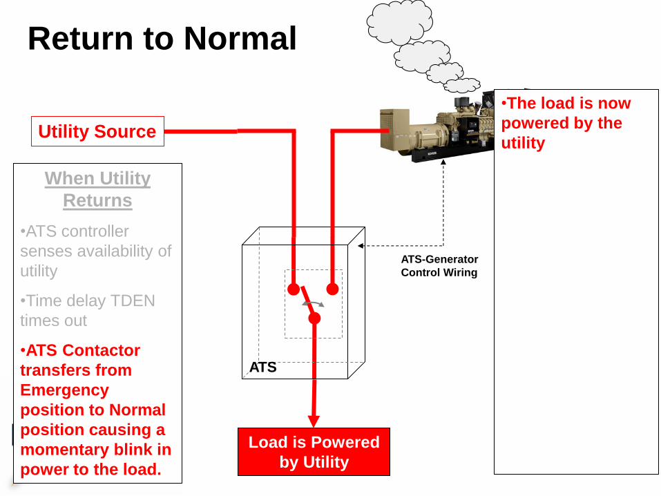
Return to Normal
When Utility
Returns
•ATS controller
senses availability of
utility
•Time delay TDEN
times out
•ATS Contactor
transfers from
Emergency
position to Normal
position causing a
momentary blink in
power to the load.
ATS-Generator
Control Wiring
ATS
Utility Source
Load is Powered
by Utility
•The load is now
powered by the
utility
•Time delay TDES
times out
• ATS sends
shutdown signal to
generator controller.
Engine stays
running in cooldown
mode
•Time delay TDEC
times out
•The engine stops
and the generator
is ready for the
next outage
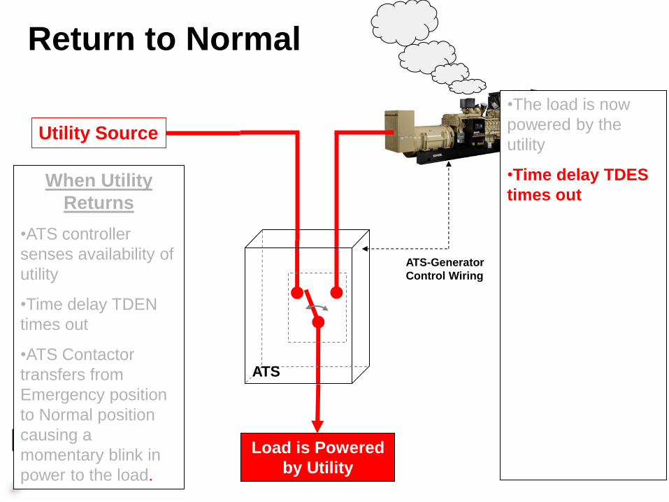
Return to Normal
When Utility
Returns
•ATS controller
senses availability of
utility
•Time delay TDEN
times out
•ATS Contactor
transfers from
Emergency position
to Normal position
causing a
momentary blink in
power to the load.
ATS-Generator
Control Wiring
ATS
Utility Source
Load is Powered
by Utility
•The load is now
powered by the
utility
•Time delay TDES
times out
• ATS sends
shutdown signal to
generator controller.
Engine stays
running in cooldown
mode
•Time delay TDEC
times out
•The engine stops
and the generator is
ready for the next
outage
Return to Normal
When Utility
Returns
•ATS controller
senses availability of
utility
•Time delay TDEN
times out
•ATS Contactor
transfers from
Emergency position
to Normal position
causing a
momentary blink in
power to the load.
ATS-Generator
Control Wiring
ATS
Utility Source
Load is Powered
by Utility
•The load is now
powered by the
utility
•Time delay TDES
times out
• ATS sends
shutdown signal to
generator
controller.
• Engine stays
running in cooldown
mode until time
delay TDEC times
out
•The engine stops
and the generator is
ready for the next
outage
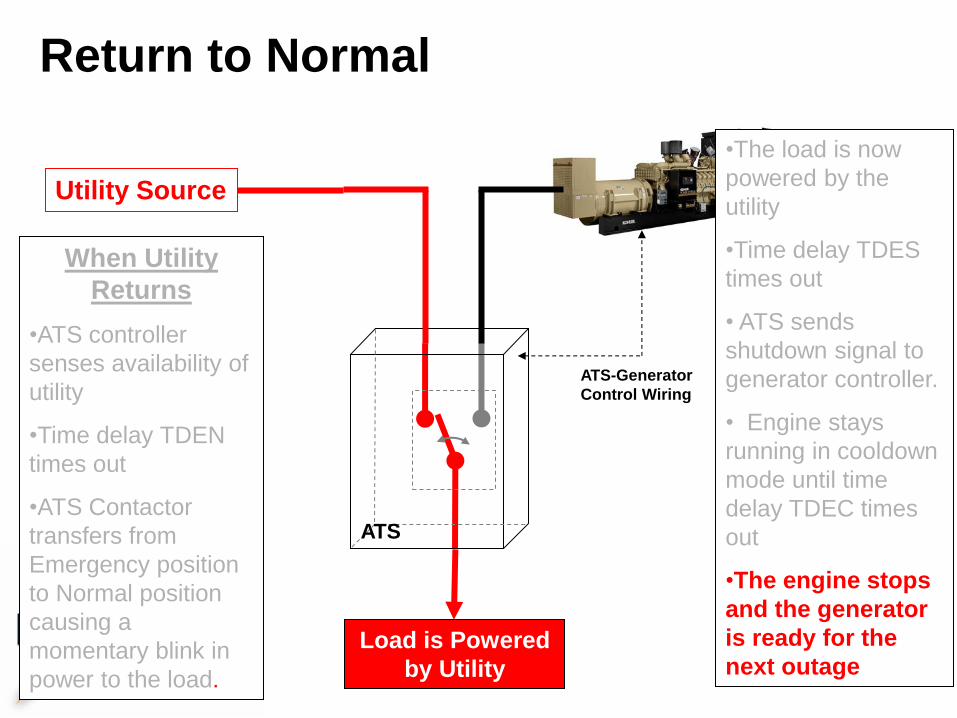
Return to Normal
When Utility
Returns
•ATS controller
senses availability of
utility
•Time delay TDEN
times out
•ATS Contactor
transfers from
Emergency position
to Normal position
causing a
momentary blink in
power to the load.
ATS-Generator
Control Wiring
ATS
Utility Source
Load is Powered
by Utility
•The load is now
powered by the
utility
•Time delay TDES
times out
• ATS sends
shutdown signal to
generator controller.
• Engine stays
running in
cooldown mode
until time delay
TDEC times out
•The engine stops
and the generator is
ready for the next
outage
Return to Normal
When Utility
Returns
•ATS controller
senses availability of
utility
•Time delay TDEN
times out
•ATS Contactor
transfers from
Emergency position
to Normal position
causing a
momentary blink in
power to the load.
ATS-Generator
Control Wiring
ATS
Utility Source
Load is Powered
by Utility
•The load is now
powered by the
utility
•Time delay TDES
times out
• ATS sends
shutdown signal to
generator controller.
• Engine stays
running in cooldown
mode until time
delay TDEC times
out
•The engine stops
and the generator
is ready for the
next outage
Bypass Isolation ATS
• For Critical Facilities
• Allows ATS to be de-energized and/or removed for service while maintaining power continuity
• Allows for manual transfer from Normal to Emergency while in bypass mode (NFPA 110, 6.4.4)
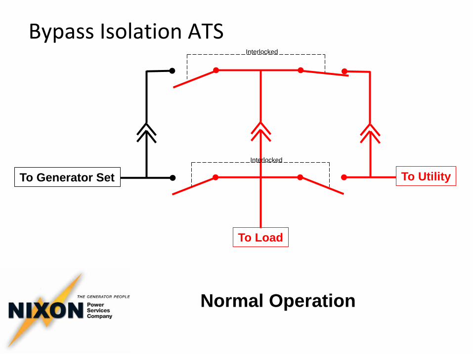
Bypass Isolation ATS
Normal Operation
To Utility To Generator Set
To Load
Interlocked
Interlocked
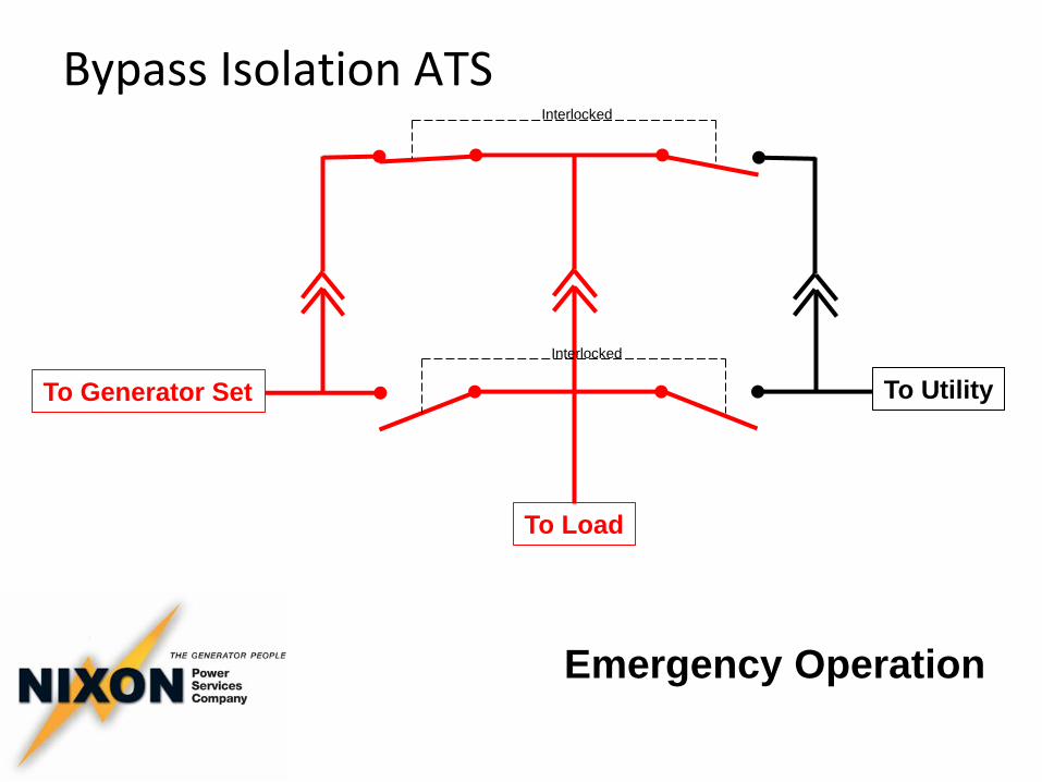
Bypass Isolation ATS
Emergency Operation
To Utility To Generator Set
To Load
Interlocked
Interlocked
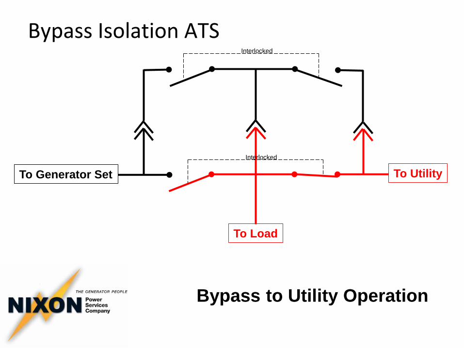
Bypass Isolation ATS
Bypass to Utility Operation
To Utility To Generator Set
To Load
Interlocked
Interlocked
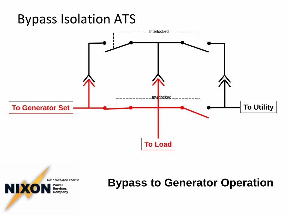
Bypass Isolation ATS
Bypass to Generator Operation
To Utility To Generator Set
To Load
Interlocked
Interlocked
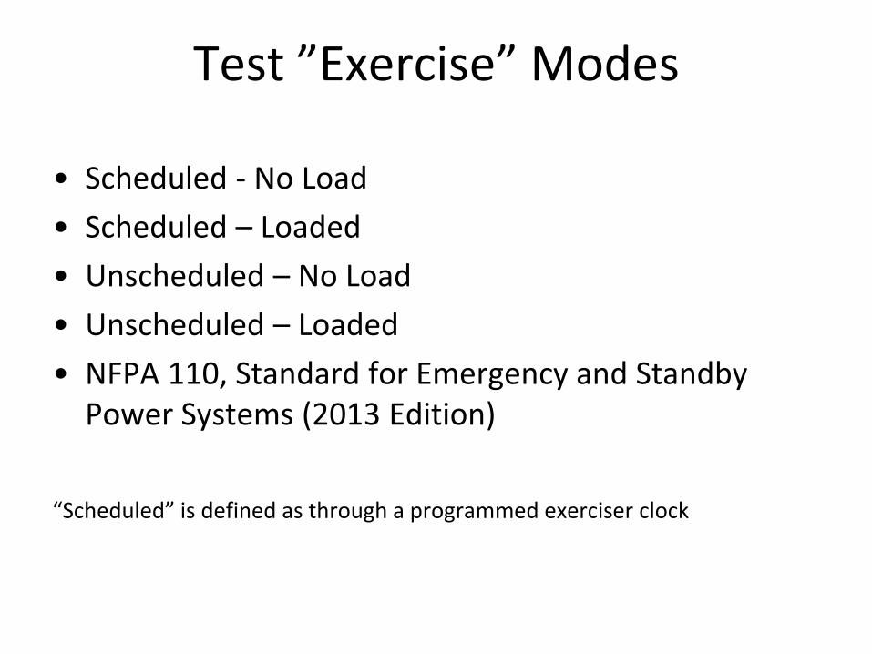
Test ”Exercise” Modes
• Scheduled - No Load
• Scheduled – Loaded
• Unscheduled – No Load
• Unscheduled – Loaded
• NFPA 110, Standard for Emergency and Standby Power Systems (2013 Edition)
“Scheduled” is defined as through a programmed exerciser clock
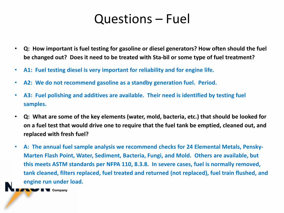
Questions – Fuel
• Q: How important is fuel testing for gasoline or diesel generators? How often should the fuel
be changed out? Does it need to be treated with Sta-bil or some type of fuel treatment?
• A1: Fuel testing diesel is very important for reliability and for engine life.
• A2: We do not recommend gasoline as a standby generation fuel. Period.
• A3: Fuel polishing and additives are available. Their need is identified by testing fuel
samples.
• Q: What are some of the key elements (water, mold, bacteria, etc.) that should be looked for
on a fuel test that would drive one to require that the fuel tank be emptied, cleaned out, and
replaced with fresh fuel?
• A: The annual fuel sample analysis we recommend checks for 24 Elemental Metals, Pensky-
Marten Flash Point, Water, Sediment, Bacteria, Fungi, and Mold. Others are available, but
this meets ASTM standards per NFPA 110, 8.3.8. In severe cases, fuel is normally removed,
tank cleaned, filters replaced, fuel treated and returned (not replaced), fuel train flushed, and
engine run under load.
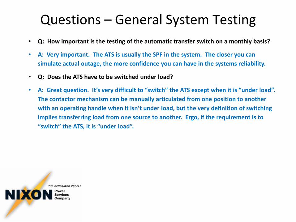
Questions – General System Testing
• Q: How important is the testing of the automatic transfer switch on a monthly basis?
• A: Very important. The ATS is usually the SPF in the system. The closer you can
simulate actual outage, the more confidence you can have in the systems reliability.
• Q: Does the ATS have to be switched under load?
• A: Great question. It’s very difficult to “switch” the ATS except when it is “under load”.
The contactor mechanism can be manually articulated from one position to another
with an operating handle when it isn’t under load, but the very definition of switching
implies transferring load from one source to another. Ergo, if the requirement is to
“switch” the ATS, it is “under load”.
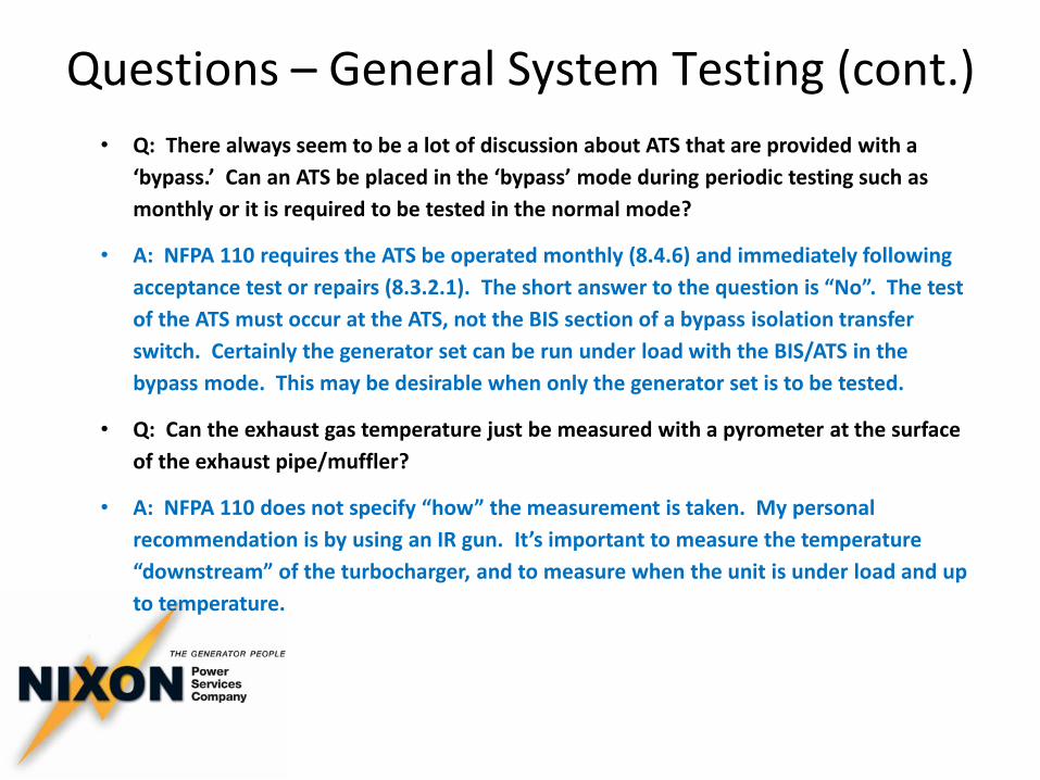
Questions – General System Testing (cont.)
• Q: There always seem to be a lot of discussion about ATS that are provided with a
‘bypass.’ Can an ATS be placed in the ‘bypass’ mode during periodic testing such as
monthly or it is required to be tested in the normal mode?
• A: NFPA 110 requires the ATS be operated monthly (8.4.6) and immediately following
acceptance test or repairs (8.3.2.1). The short answer to the question is “No”. The test
of the ATS must occur at the ATS, not the BIS section of a bypass isolation transfer
switch. Certainly the generator set can be run under load with the BIS/ATS in the
bypass mode. This may be desirable when only the generator set is to be tested.
• Q: Can the exhaust gas temperature just be measured with a pyrometer at the surface
of the exhaust pipe/muffler?
• A: NFPA 110 does not specify “how” the measurement is taken. My personal
recommendation is by using an IR gun. It’s important to measure the temperature
“downstream” of the turbocharger, and to measure when the unit is under load and up
to temperature.
Questions – Load Testing
• Q: How important is periodic load testing of a generator? Is 30% good enough or should a
more substantial load be place on the unit?
• A: Recommend 100% rated load test bi-annually on diesels. For diesel engine sets, NFPA
110 (8.4.2)(2) requires monthly 30 minute test at minimum of 30% standby nameplate
rating, whereas it doesn’t specify a minimum load for spark ignited engine sets (8.4.2.4).
• Q: Can the load test be just the supplied load? If so, is there a minimum % of the name
plate rating that the service load should meet?
• A: As long as there is sufficient available load to meet the requirements of NFPA 110
(8.4.2) facility load is only ok.
Questions – Load Testing (cont.)
• Q: Are there significant hazards with using a portable load bank to test with? Do you
recommend a permanent disconnect for the load bank or can it just be connected to the
generator terminals?
• A1: Yes. Electrical hazards associated with ground laid cable, trip hazards, intense heat
rejected from the load banks. Portable load bank operations are best left to professionals.
Additionally, if stationary generator is to be disconnected from facility load while it is
being load banked, a temporary portable generator would need to be connected in its
place in anticipation of an unforeseen utility outage.
• A2: A permanent load bank connection point with its own breaker is desirable and in
some cases essential. NFPA 110 (8.4.2.2) and (8.4.2.4.2) requires that the load bank be
“automatically replaced with the emergency loads” (ie disconnected from the load bank
and generator power transferred to connected facility load) in the event that utility fails
while the generator is in a load bank test.
Questions – Load Testing (cont.)
• Q: When can a permanent test bank be added to a generator? Does the permanent bank
have to be from the manufacturer of the gen set? Are there generic permanent test
banks?
• A1: A permanent load bank can be added to the system after the fact. It is preferred that
it be designed in, specified, and procured along with the new generator set and other
EPSS equipment.
• A2: The load bank does not necessarily come from the generator set provider, but there
are many obvious advantages to procuring it along with the generator set. There are a
number of American companies that manufacture and sell load banks. Controls interface
after the fact may prove difficult when purchased from multiple sources.
• Q: Can you install just one load rod that will provide a 50% load and call it good enough or
do you incremental loads?
• A: NFPA 110 (8.4.2.3) requires 75% (of nameplate kW rating) load for 1 hour if (8.4.2) is
not met.
Questions – General System Testing (cont.)
• Q: The code (Section 8.4.2) discusses the manufacturers recommend exhaust gas
temperatures for the monthly test. Is there a magical temperature that all generators
should be tested to or if there a different exhaust gas temperature for every
model/brand? Can the exhaust gas temperature be determined with a non-contact IR
temperature scanner on the exhaust pipe?
• A: Sorry, there is no magical temperature. Each is specified on the manufacturers data
sheet included with the operation and service literature. Diesel exhaust is typically in
the 950F range. Spark ignited exhaust (natural gas or LP) is typically in the 1200F
range.
• How should a generator be started when conducting a monthly, annual, or tri-annual
test that requires the generator to be tested under loaded conditions?
• A: NFPA 110 (8.4.3) Test should be initiated using test switch on ATS or by opening the
utility breaker to simulate an outage. Also, (8.4.4) load test is to include complete cold
starts.
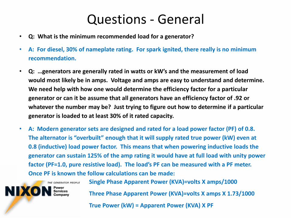
Questions - General • Q: What is the minimum recommended load for a generator?
• A: For diesel, 30% of nameplate rating. For spark ignited, there really is no minimum
recommendation.
• Q: …generators are generally rated in watts or kW’s and the measurement of load
would most likely be in amps. Voltage and amps are easy to understand and determine.
We need help with how one would determine the efficiency factor for a particular
generator or can it be assume that all generators have an efficiency factor of .92 or
whatever the number may be? Just trying to figure out how to determine if a particular
generator is loaded to at least 30% of it rated capacity.
• A: Modern generator sets are designed and rated for a load power factor (PF) of 0.8.
The alternator is “overbuilt” enough that it will supply rated true power (kW) even at
0.8 (inductive) load power factor. This means that when powering inductive loads the
generator can sustain 125% of the amp rating it would have at full load with unity power
factor (PF=1.0, pure resistive load). The load’s PF can be measured with a PF meter.
Once PF is known the follow calculations can be made:
Single Phase Apparent Power (KVA)=volts X amps/1000
Three Phase Apparent Power (KVA)=volts X amps X 1.73/1000
True Power (kW) = Apparent Power (KVA) X PF

Notes

Notes