Embed Size (px)
Citation preview
PRESENTS YOUR
OPERATORS MANUAL
BALDOR GENERATORS
3815 OREGON STREET OSHKOSH, WI 54902 PHONE: 920-236-4200 FAX: 920-236-4219
FORM#: S-PSG-002-91 REVISED: 2/25/02 C:\ISO9001\FORMS\S-PSG-00291.MSW EFFECTIVE: 5/3/01
STANDBY PERMANENT MOUNT SERIES GENERATOR

FORWARD This manual contains the information you need to safely and efficiently operate your generator set. During the preparation of this manual every effort was made to ensure the accuracy of its contents. Never operate this generator set without first carefully reading this manual and observing all the safety warnings it presents. While safety is built into every Baldor Pow'R Gard generator set, careless or improper operation could possibly result in mechanical failure, property damage, severe injury or death. Note that this manual covers only very basic information in regards to the engine. A separate owner's manual for the engine is supplied with this unit for your use. Please refer to this manual for information relative to engine operation, maintenance, recommendations and additional safety warnings. As soon as you receive your generator set, inspect it closely for shipping damage. If you find some damage, notify the transportation company immediately and file a freight damage claim. Think of this manual as a tool to help you get the most out of your generator set. We strongly suggest that you keep this manual with your generator set and refer to it when questions arise in regards to its operation. Baldor Generators, formerly Pow'R Gard Generator Corporation has been in business since 1965. The generator sets we manufacture have earned the reputation of being of high quality and a dependable product. We take pride in this fact and continue to keep our quality standards high on our list of priorities. We are also constantly researching new technological ideas to determine if they could be used to make our generator sets even better. Thank you for purchasing your Baldor Pow'R Gard Generator Set.
- i -

Place protective covers and guards over the rotating parts, if rotating parts such as the drive shaft, pulley, belt, etc. are left exposed, they are potentially hazardous.
When cleaning, repairing or inspecting, make sure all moving parts have stopped.
Prior to working on the generator set, disconnect the spark plug and battery to prevent accidental starting.
Use only original equipment or authorized replacement parts. Use of correct parts will assure the operator of
the safety integrity that was designed into the unit.
Unauthorized modifications to the generator set may impair the function and/or safety of the unit.
Do not operate the generator set without a muffler. Inspect periodically and replace if necessary.
Do not touch the hot exhaust components or the high voltage spark plug and coil terminals. While Spark Plug Voltages are not normally lethal, an involuntary jerk of the hand caused by a hot surface or by an electrical shock can result in injury.
Repair of electrical generating equipment requires specialized skills. Repair personnel must have a
thorough understanding of generator and small engine repair procedures.
Never inhale exhaust gases. They contain carbon monoxide; a colorless, odorless and extremely dangerous gas that can cause unconsciousness or death. Symptoms of carbon monoxide poisoning can include: dizziness, nausea, headaches, sleepiness, vomiting or incoherency. If you or anyone else experiences any of these symptoms, get out into the fresh air immediately. Shut the unit down and do not operate it until it has been inspected and, if necessary, repaired.
Never Operate the generator set indoors or in a poorly ventilated area such as a tunnel or cave.
CALIFORNIA PROPOSITION 65 WARNING: engine exhaust from this product contains chemicals known to
the state of California to cause cancer, birth defects or other reproductive harm.
Know how to stop the engine quickly and understand the operation of all controls.
- ii -
Never permit anyone to operate the generator set without proper instructions.
Never allow children to operate the generator set.
Children and pets must be kept away from the area of operation due to the possibility of burns from hot
engine components or injury from any equipment the generator set is powering.
Always wear eye protection and Hearing protection when working near the generator set.
Operate the generator set only with the guards, shields and other safety items in place and working properly.
Do not put hands, feet, tools or other objects near rotating parts.
Use reasonable care when moving or lifting the unit. The generator set may move around inside the wrap
frame creating "Pinch Points".
Do not run the generator set while it is being moved.
Do not support the generator set from the top of the wrap frame.
Do not operate the generator set while under the influence of alcohol, drugs or medication.
When transporting or using a generator set with the wheel option, secure the unit to prevent it from moving around.
Do not tamper with or change the engine speed as it has been preset at the factory for proper operation.
Keep hands and face away from the carburetor when the air cleaner is being moved. A sudden backfire can
cause serious burns.
Be careful of hot parts. The muffler and other generator parts become very hot while the engine is running.
Do not "jump start" the generator set.
Sulfuric acid can cause severe injury and can give off gases, which are corrosive and potentially explosive. Avoid contact with skin, eyes, and clothing. In case of contact, flush area immediately with water.
When transporting a generator set, secure it to prevent it from moving or shifting.
Know how to stop the engine quickly and understand the operation of all controls.
Do not operate electrical equipment while standing in water, on wet ground or with wet hands or shoes.
Use extreme caution when working on electrical components. Potentially dangerous voltage is present when the engine is running.
- iii -
Always treat the electrical circuits as if they were energized.
Disconnect all leads plugged into the unit Prior to working on it.
Have the electrical circuits serviced only by qualified technicians.
Inspect wiring frequently and replace frayed, broken or poor leads.
Do not connect this unit to any building's electrical system unless you utilize an approved transfer switch or the main service entrance switch has been disconnected and locked open.
Circuit overload protection must be provided in accordance with national electrical codes and local
regulations.
Check GFCI Receptacles monthly by using the "Test" and "Reset" buttons designed into them.
Depending on your application it may be mandatory to ground or not ground this unit to earth ground. Comply with local electrical codes.
FOR GASOLINE OR DIESEL POWERED GENERATOR SETS
Operate the generator set on a level surface. If the generator set is tilted, fuel spillage may result.
Handle fuel with care. It is highly flammable. Use only clean, properly marked and approved safety containers for refueling and storing fuel.
Stop the engine and allow it to cool before refueling.
Do not overfill the fuel tank. Only fill the tank to within 1/2" of the top of the tank to allow space for fuel
expansion.
If fuel is spilled, wipe it up carefully and wait until the fuel has dried before starting the engine.
Make sure the fuel cap is properly closed after refueling.
Never operate the generator set while smoking.
Never operate the generator set near an open flame.
Never store the generator set with fuel in the tank indoors or in an enclosed, poorly ventilated enclosure where fuel fumes may reach an open flame, electrical spark or pilot light as on a furnace, water heater, clothes dryer, etc.
When transporting over long distances or rough roads, drain the fuel tank to prevent leakage and spillage.
- iv -
FOR GASOLINE OR DIESEL POWERED GENERATOR SETS
Check all fuel supply piping and their connections on a monthly basis for fuel leaks.
Use only approved piping and componentry in your fuel supply system.
A professional, experienced technician should only install the fuel supply system.
Do not run the fuel line up against any sharp objects.
Comply with NFPA regulations and your local codes in regard to shut-off valves, regulators, etc. and any other recommendations or requirements they may have.
Keep the generator set at least three feet away from buildings or other structures.
Keep the generator set away from flammable and other hazardous materials (trash, rags, lubricants, explosives, paints, etc.)
Keep the generator set free of grass, leaves and excessive grease and oils.
Allow the generator set to cool before transporting it or storing it indoors.
Have fire extinguisher accessible and nearby while operating the generator set.
This generator set must not be used on or near any forest covered brush covered or grass covered land
unless the engine's exhaust system is equipped with a spark arrester and it must be maintained in effective working order by the operator.
Operation inside an enclosed compartment or building is a potential fire hazard and should not be done
unless approval is obtained from Baldor Generators. Engine/Generator overheating can cause severe damage due to restricted, obstructed or improper airflow that is necessary for the proper cooling of the unit.
Hot exhaust gases being discharged by the engine must never be directed toward anything that could catch
fire or explode.
- v -
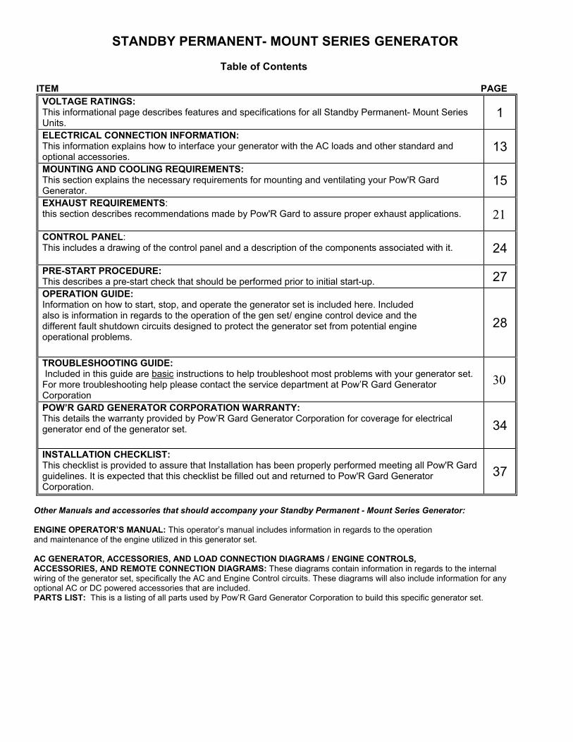
STANDBY PERMANENT- MOUNT SERIES GENERATOR Table of Contents
ITEM PAGE
VOLTAGE RATINGS: This informational page describes features and specifications for all Standby Permanent- Mount Series Units.
1 ELECTRICAL CONNECTION INFORMATION: This information explains how to interface your generator with the AC loads and other standard and optional accessories.
13 MOUNTING AND COOLING REQUIREMENTS: This section explains the necessary requirements for mounting and ventilating your Pow'R Gard Generator.
15 EXHAUST REQUIREMENTS: this section describes recommendations made by Pow'R Gard to assure proper exhaust applications. 21 CONTROL PANEL: This includes a drawing of the control panel and a description of the components associated with it. 24 PRE-START PROCEDURE: This describes a pre-start check that should be performed prior to initial start-up. 27 OPERATION GUIDE: Information on how to start, stop, and operate the generator set is included here. Included also is information in regards to the operation of the gen set/ engine control device and the different fault shutdown circuits designed to protect the generator set from potential engine operational problems.
28
TROUBLESHOOTING GUIDE: Included in this guide are basic instructions to help troubleshoot most problems with your generator set. For more troubleshooting help please contact the service department at Pow’R Gard Generator Corporation
30
POW’R GARD GENERATOR CORPORATION WARRANTY: This details the warranty provided by Pow’R Gard Generator Corporation for coverage for electrical generator end of the generator set.
34
INSTALLATION CHECKLIST: This checklist is provided to assure that Installation has been properly performed meeting all Pow'R Gard guidelines. It is expected that this checklist be filled out and returned to Pow'R Gard Generator Corporation.
37
Other Manuals and accessories that should accompany your Standby Permanent - Mount Series Generator: ENGINE OPERATOR’S MANUAL: This operator’s manual includes information in regards to the operation and maintenance of the engine utilized in this generator set. AC GENERATOR, ACCESSORIES, AND LOAD CONNECTION DIAGRAMS / ENGINE CONTROLS, ACCESSORIES, AND REMOTE CONNECTION DIAGRAMS: These diagrams contain information in regards to the internal wiring of the generator set, specifically the AC and Engine Control circuits. These diagrams will also include information for any optional AC or DC powered accessories that are included. PARTS LIST: This is a listing of all parts used by Pow’R Gard Generator Corporation to build this specific generator set.
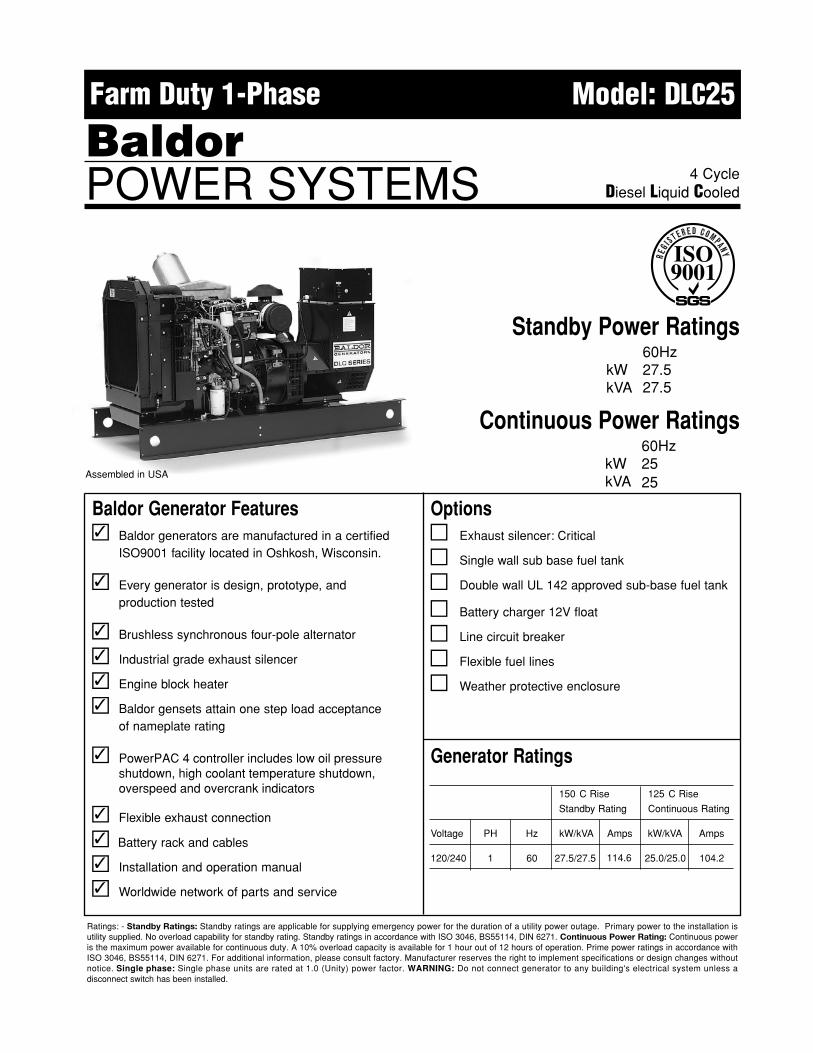
Baldor Generator Features� Baldor generators are manufactured in a certified
ISO9001 facility located in Oshkosh, Wisconsin.
� Every generator is design, prototype, andproduction tested
� Brushless synchronous four-pole alternator
� Industrial grade exhaust silencer
� Engine block heater
� Baldor gensets attain one step load acceptanceof nameplate rating
� PowerPAC 4 controller includes low oil pressureshutdown, high coolant temperature shutdown,overspeed and overcrank indicators
� Flexible exhaust connection
�� Installation and operation manual
� Worldwide network of parts and service
Generator Ratings
150 � C Rise 125 � C Rise
Standby Rating Continuous Rating
Voltage PH Hz kW/kVA Amps kW/kVA Amps
120/240 1 60 25.0/25.0 104.2
Options� Exhaust silencer: Critical
� Single wall sub base fuel tank
� Double wall UL 142 approved sub-base fuel tank
� Battery charger 12V float
� Line circuit breaker
� Flexible fuel lines
� Weather protective enclosure
4 CycleDiesel Liquid Cooled
Standby Power Ratings60Hz
kW 27.527.5kVA
Continuous Power Ratings60Hz
kW 2525kVA
Farm Duty 1-Phase Model: DLC25
BaldorPOWER SYSTEMS
�
�
�
�
�
�
�
�
�
�
�
Assembled in USA
Battery rack and cables
Ratings: - Standby Ratings: Standby ratings are applicable for supplying emergency power for the duration of a utility power outage. Primary power to the installation is utility supplied. No overload capability for standby rating. Standby ratings in accordance with ISO 3046, BS55114, DIN 6271. Continuous Power Rating: Continuous power is the maximum power available for continuous duty. A 10% overload capacity is available for 1 hour out of 12 hours of operation. Prime power ratings in accordance with ISO 3046, BS55114, DIN 6271. For additional information, please consult factory. Manufacturer reserves the right to implement specifications or design changes without notice. Single phase: Single phase units are rated at 1.0 (Unity) power factor. WARNING: Do not connect generator to any building's electrical system unless a disconnect switch has been installed.
27.5/27.5 114.6
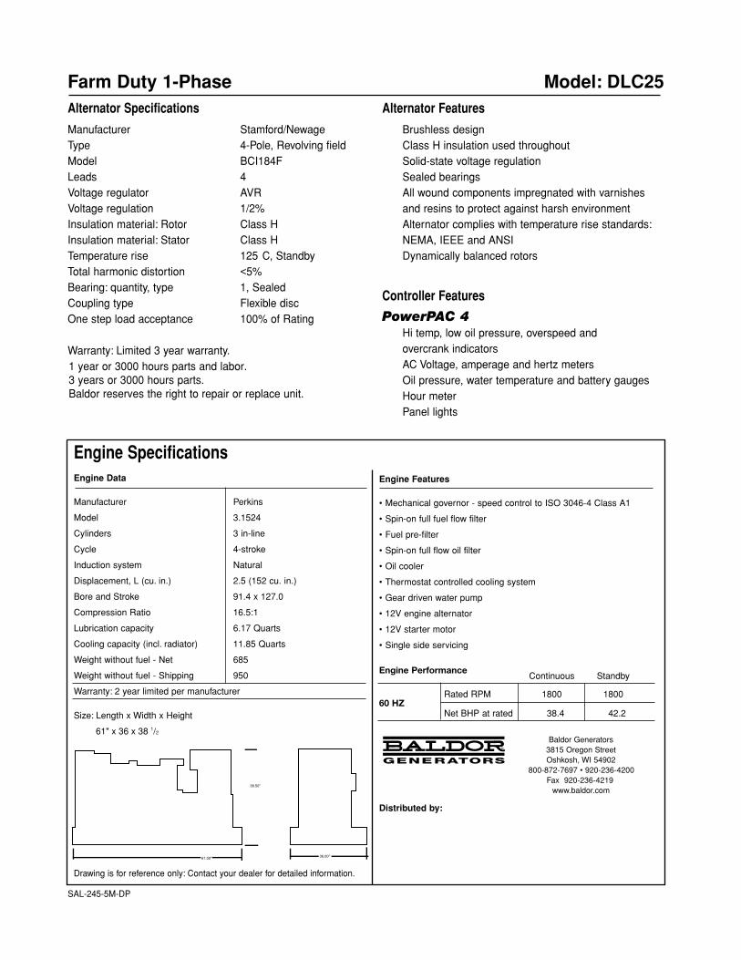
Engine SpecificationsEngine Data
Manufacturer Perkins
Model 3.1524
Cylinders 3 in-line
Cycle 4-stroke
Induction system Natural
Displacement, L (cu. in.) 2.5 (152 cu. in.)
Bore and Stroke 91.4 x 127.0
Compression Ratio 16.5:1
Lubrication capacity 6.17 Quarts
Cooling capacity (incl. radiator) 11.85 Quarts
Weight without fuel - Net 685
Weight without fuel - Shipping 950
Warranty: 2 year limited per manufacturer
Size: Length x Width x Height
61" x 36 x 38 1/2
Drawing is for reference only: Contact your dealer for detailed information.
Farm Duty 1-Phase Model: DLC25Alternator Specifications
Manufacturer Stamford/NewageType 4-Pole, Revolving fieldModel BCI184FLeads 4Voltage regulator AVRVoltage regulation 1/2%Insulation material: Rotor Class HInsulation material: Stator Class HTemperature rise 125� C, StandbyTotal harmonic distortion <5%Bearing: quantity, type 1, SealedCoupling type Flexible discOne step load acceptance 100% of Rating
Warranty: Limited 3 year warranty.1 year or 3000 hours parts and labor. 3 years or 3000 hours parts.Baldor reserves the right to repair or replace unit.
Alternator Features
Brushless designClass H insulation used throughoutSolid-state voltage regulationSealed bearingsAll wound components impregnated with varnishesand resins to protect against harsh environmentAlternator complies with temperature rise standards:NEMA, IEEE and ANSIDynamically balanced rotors
Controller Features
PowerPAC 4Hi temp, low oil pressure, overspeed andovercrank indicatorsAC Voltage, amperage and hertz metersOil pressure, water temperature and battery gaugesHour meterPanel lights
Engine Features
• Mechanical governor - speed control to ISO 3046-4 Class A1
• Spin-on full fuel flow filter
• Fuel pre-filter
• Spin-on full flow oil filter
• Oil cooler
• Thermostat controlled cooling system
• Gear driven water pump
• 12V engine alternator
• 12V starter motor
• Single side servicing
Engine PerformanceContinuous Standby
60 HZRated RPM 1800 1800
Net BHP at rated 38.4 42.2
Baldor Generators3815 Oregon StreetOshkosh, WI 54902
800-872-7697 • 920-236-4200Fax 920-236-4219
www.baldor.com
Distributed by:
36.00"
38.50"
61.00"
SAL-245-5M-DP
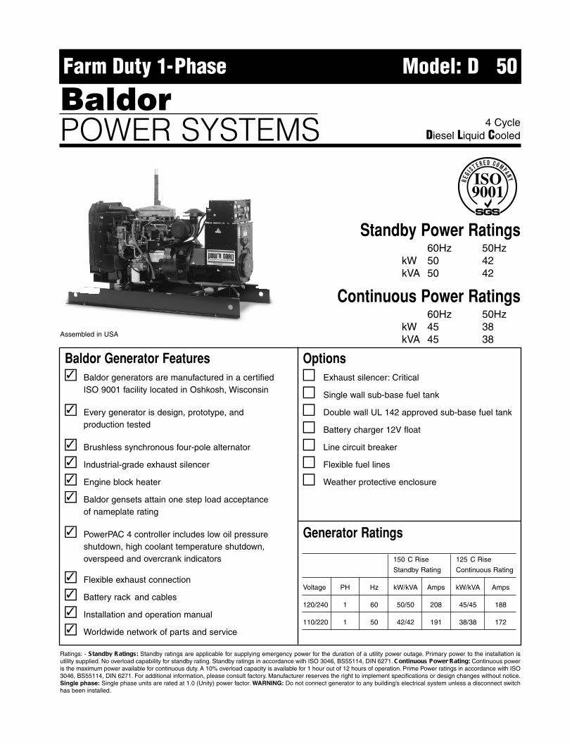
Baldor Generator Features� Baldor generators are manufactured in a certified
ISO 9001 facility located in Oshkosh, Wisconsin
� Every generator is design, prototype, andproduction tested
� Brushless synchronous four-pole alternator
� Industrial-grade exhaust silencer
� Engine block heater
� Baldor gensets attain one step load acceptanceof nameplate rating
� PowerPAC 4 controller includes low oil pressureshutdown, high coolant temperature shutdown, overspeed and overcrank indicators
� Flexible exhaust connection
� Battery rack and cables
� Installation and operation manual
� Worldwide network of parts and service
Ratings: - Standby Ratings: Standby ratings are applicable for supplying emergency power for the duration of a utility power outage. Primary power to the installation isutility supplied. No overload capability for standby rating. Standby ratings in accordance with ISO 3046, BS55114, DIN 6271. C ontinuous Power Rating: Continuous poweris the maximum power available for continuous duty. A 10% overload capacity is available for 1 hour out of 12 hours of operation. Prime Power ratings in accordance with ISO3046, BS55114, DIN 6271. For additional information, please consult factory. Manufacturer reserves the right to implement specifications or design changes without notice.Single phase: Single phase units are rated at 1.0 (Unity) power factor. WARNING: Do not connect generator to any building’s electrical system unless a disconnect switchhas been installed.
Generator Ratings
150 � C Rise 125 � C Rise
Standby Rating Continuous Rating
Voltage PH Hz kW/kVA Amps kW/kVA Amps
120/240 1 60 50/50 208 45/45 188
110/220 1 50 42/42 191 38/38 172
Options� Exhaust silencer: Critical
� Single wall sub-base fuel tank
� Double wall UL 142 approved sub-base fuel tank
� Battery charger 12V float
� Line circuit breaker
� Flexible fuel lines
� Weather protective enclosure
4 CycleDiesel Liquid Cooled
Standby Power Ratings60Hz 50Hz
kW 50 42kVA 50 42
Continuous Power Ratings60Hz 50Hz
kW 45 38kVA 45 38
Farm Duty 1-Phase Model: D��50
BaldorPOWER SYSTEMS
�
�
�
�
�
�
�
�
�
�
�
Assembled in USA
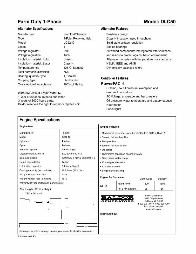
Engine SpecificationsEngine Data
Manufacturer Perkins
Model 1004-40T
Cylinders 4 in-line
Cycle 4-stroke
Induction system Turbocharged
Displacement, L (cu. in.) 3.99 (243.5 cu. in.)
Bore and Stroke 100.0 MM x 127.0 MM 3.94 x 5
Compression Ratio 17.25:1
Lubrication capacity 8.4 liters (9 qts.)
Cooling capacity (incl. radiator) 18.8 liters (23.4 qts.)
Weight without fuel - Net 1727
Weight without fuel - Shipping 1812
Warranty: 2 year limited per manufacturer
Size: Length x Width x Height
783⁄4" x 36" x 45"
Drawing is for reference only: Contact your dealer for detailed information.
Farm Duty 1-Phase Model: DLC50Alternator Specifications
Manufacturer Stamford/NewageType 4-Pole, Revolving fieldModel UC224DLeads 4Voltage regulator AVRVoltage regulation 1/2%Insulation material: Rotor Class HInsulation material: Stator Class HTemperature rise 125� C, StandbyTotal harmonic distortion <5%Bearing: quantity, type 1, SealedCoupling type Flexible discOne step load acceptance 100% of Rating
Warranty: Limited 3 year warranty.1 year or 3000 hours parts and labor. 3 years or 3000 hours parts.Baldor reserves the right to repair or replace unit.
Alternator Features
Brushless designClass H insulation used throughoutSolid-state voltage regulationSealed bearingsAll wound components impregnated with varnishesand resins to protect against harsh environmentAlternator complies with temperature rise standards:NEMA, IEEE and ANSIDynamically balanced rotors
Controller Features
PowerPAC 4Hi temp, low oil pressure, overspeed andovercrank indicatorsAC Voltage, amperage and hertz metersOil pressure, water temperature and battery gaugesHour meterPanel lights
Engine Features
• Mechanical governor - speed control to ISO 3046-4 Class A1
• Spin-on full fuel flow filter
• Fuel pre-filter
• Spin-on full flow oil filter
• Oil cooler
• Thermostat controlled cooling system
• Gear driven water pump
• 12V engine alternator
• 12V starter motor
• Single side servicing
Engine PerformanceContinuous Standby
60 HZRated RPM 1800 1800
Net BHP at rated 95 86
Baldor Generators3815 Oregon StreetOshkosh, WI 54902
1-800-872-7697 • 1-920-236-4200Fax 1-920-236-4219
www.baldor.com
Distributed by:
36.00"
45.00"
78.75"
SAL-160-10M-SG

Baldor Generator Features� Baldor generators are manufactured in a certified
ISO 9001 facility located in Oshkosh, Wisconsin
� Every generator is design, prototype, andproduction tested
� Brushless synchronous four-pole alternator
� Industrial-grade exhaust silencer
� Engine block heater
� Baldor gensets attain one step load acceptanceof nameplate rating
� PowerPAC 4 controller includes low oil pressureshutdown, high coolant temperature shutdown, overspeed and overcrank indicators
� Flexible exhaust connection
� Battery rack and cables
� Installation and operation manual
� Worldwide network of parts and service
Ratings: - Standby Ratings: Standby ratings are applicable for supplying emergency power for the duration of a utility power outage. Primary power to the installation isutility supplied. No overload capability for standby rating. Standby ratings in accordance with ISO 3046, BS55114, DIN 6271. C ontinuous Power Rating: Continuous poweris the maximum power available for continuous duty. A 10% overload capacity is available for 1 hour out of 12 hours of operation. Prime Power ratings in accordance with ISO3046, BS55114, DIN 6271. For additional information, please consult factory. Manufacturer reserves the right to implement specifications or design changes without notice.Single phase: Single phase units are rated at 1.0 (Unity) power factor. WARNING: Do not connect generator to any building’s electrical system unless a disconnect switchhas been installed.
Generator Ratings
150 � C Rise 125 � C Rise
Standby Rating Continuous Rating
Voltage PH Hz kW/kVA Amps kW/kVA Amps
120/240 1 60 60/60 250 54/54 225
110/220 1 50 50/50 227 45/45 205
Options� Exhaust silencer: Critical
� Single wall sub-base fuel tank
� Double wall UL 142 approved sub-base fuel tank
� Battery charger 12V float
� Line circuit breaker
� Flexible fuel lines
� Weather protective enclosure
4 CycleDiesel Liquid Cooled
Standby Power Ratings60Hz 50Hz
kW 60 50kVA 60 50
Continuous Power Ratings60Hz 50Hz
kW 54 45kVA 54 45
Farm Duty 1-Phase Model: D��60
BaldorPOWER SYSTEMS
�
�
�
�
�
�
�
�
�
�
�
Assembled in USA
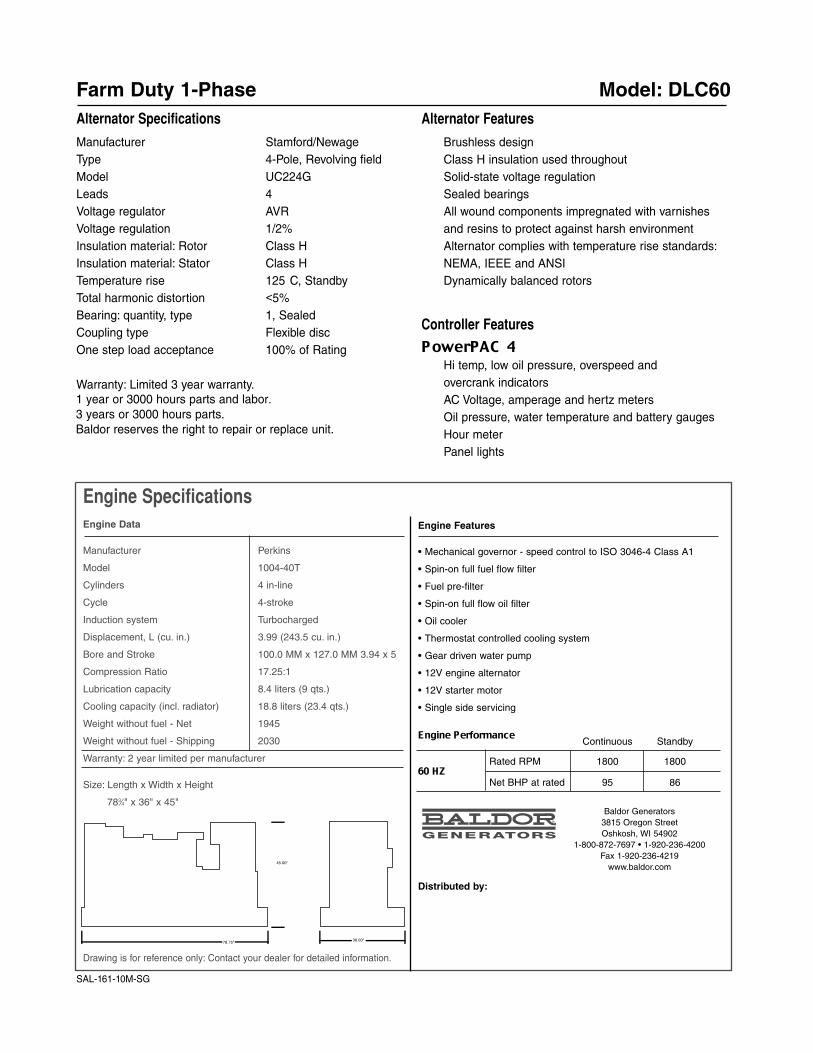
Engine SpecificationsEngine Data
Manufacturer Perkins
Model 1004-40T
Cylinders 4 in-line
Cycle 4-stroke
Induction system Turbocharged
Displacement, L (cu. in.) 3.99 (243.5 cu. in.)
Bore and Stroke 100.0 MM x 127.0 MM 3.94 x 5
Compression Ratio 17.25:1
Lubrication capacity 8.4 liters (9 qts.)
Cooling capacity (incl. radiator) 18.8 liters (23.4 qts.)
Weight without fuel - Net 1945
Weight without fuel - Shipping 2030
Warranty: 2 year limited per manufacturer
Size: Length x Width x Height
783⁄4" x 36" x 45"
Drawing is for reference only: Contact your dealer for detailed information.
Farm Duty 1-Phase Model: DLC60Alternator Specifications
Manufacturer Stamford/NewageType 4-Pole, Revolving fieldModel UC224GLeads 4Voltage regulator AVRVoltage regulation 1/2%Insulation material: Rotor Class HInsulation material: Stator Class HTemperature rise 125� C, StandbyTotal harmonic distortion <5%Bearing: quantity, type 1, SealedCoupling type Flexible discOne step load acceptance 100% of Rating
Warranty: Limited 3 year warranty.
Alternator Features
Brushless designClass H insulation used throughoutSolid-state voltage regulationSealed bearingsAll wound components impregnated with varnishesand resins to protect against harsh environmentAlternator complies with temperature rise standards:NEMA, IEEE and ANSIDynamically balanced rotors
Controller Features
PowerPAC 4Hi temp, low oil pressure, overspeed andovercrank indicatorsAC Voltage, amperage and hertz metersOil pressure, water temperature and battery gaugesHour meterPanel lights
Engine Features
• Mechanical governor - speed control to ISO 3046-4 Class A1
• Spin-on full fuel flow filter
• Fuel pre-filter
• Spin-on full flow oil filter
• Oil cooler
• Thermostat controlled cooling system
• Gear driven water pump
• 12V engine alternator
• 12V starter motor
• Single side servicing
Engine PerformanceContinuous Standby
60 HZRated RPM 1800 1800
Net BHP at rated 95 86
Baldor Generators3815 Oregon StreetOshkosh, WI 54902
1-800-872-7697 • 1-920-236-4200Fax 1-920-236-4219
www.baldor.com
Distributed by:
SAL-161-10M-SG
36.00"
45.00"
78.75"
1 year or 3000 hours parts and labor. 3 years or 3000 hours parts.Baldor reserves the right to repair or replace unit.

Baldor Generator Features� Baldor generators are manufactured in a certified
ISO9001 facility located in Oshkosh, Wisconsin.
� Every generator is design, prototype, andproduction tested
� Brushless synchronous four-pole alternator
� Industrial grade exhaust silencer
� Engine block heater
� Baldor gensets attain one step load acceptanceof nameplate rating
� PowerPAC 4 controller includes low oil pressure,high coolant temperature, overspeed and overcrank shutdowns with indicator lights
� Flexible exhaust connection
�� Installation and operation manual
� Worldwide network of parts and service
Ratings: - Standby Ratings: Standby ratings are applicable for supplying emergency power for the duration of a utility power outage. Primary power to the installation isutility supplied. No overload capability for standby rating. Standby ratings in accordance with ISO 3046, BS55114, DIN 6271. C ontinuous Power Rating: Continuouspower is the maximum power available for continuous duty. A 10% overload capacity is available for 1 hour out of 12 hours of operation. Continuous Power ratings inaccordance with ISO 3046, BS55114, DIN 6271. For additional information, please consult factory. Manufacturer reserves the right to implement specifications or designchanges without notice. Single phase: Single phase units are rated at 1.0 (Unity) power factor.
Generator Ratings
150 � C Rise 125 � C Rise
Standby Rating Continuous Rating
Voltage PH Hz kW/kVA Amps kW/kVA Amps
120/240 1 60 75/75 312 68/68 283
110/220 1 50 63/63 286 57/57 259
Options� Exhaust silencer: Critical
� Single wall sub base fuel tank
� Double wall UL 142 approved sub base fuel tank
� Battery charger 12V float
� Line circuit breaker
� Flexible fuel lines
� Weather protective enclosure
4 CycleDiesel Liquid Cooled
Standby Power Ratings60Hz 50Hz
kW 75 63kVA 75 63
Continuous Power Ratings60Hz 50Hz
kW 68 57kVA 68 57
Farm Duty 1-Phase Model: D��75
BaldorPOWER SYSTEMS
�
�
�
�
�
�
�
�
�
�
�
Assembled in USA
Battery rack and cables

Engine SpecificationsEngine Data
Manufacturer Perkins
Model 1004-40TW
Cylinders 4 in-line
Cycle 4-stroke
Induction system Turbocharged
Displacement, L (cu. in.) 3.99 (243.5 cu. in.)
Bore and Stroke 100.0 MM x 127.0 MM 3.94 x 5
Compression Ratio 17.3:1
Lubrication capacity 8.5 liters (9 qts.)
Cooling capacity (inc. radiator) 22.2 liters (23.4 qts.)
Weight without fuel - Net 2035
Weight without fuel - Shipping 2110
Warranty: 2 year limited per manufacturer
Size: Length x Width x Height
783⁄4" x 36" x 45"
Drawing is for reference only: Contact your dealer for detailed information.
Farm Duty 1-Phase Model: DLC75Alternator Specifications
Manufacturer Stamford/NewageType 4-Pole, Revolving fieldModel UCI224GLeads 4Voltage regulator AVRVoltage regulation 1/2%Insulation material: Rotor Class HInsulation material: Stator Class HTemperature rise 125 � CTotal harmonic distortion <5%Bearing: quantity, type 1, SealedCoupling type Flexible discOne step load acceptance 100% of Rating
Warranty: Limited 3 year warranty.
Alternator Features
Brushless designClass H insulation used throughoutSolid state voltage regulationSealed bearingsAll wound components impregnated with varnishesand resins to protect against harsh environmentAlternator complies with temperature rise standards:NEMA, IEEE and ANSIDynamically balanced rotors
Controller Features
PowerPAC 4Hi temp, low oil pressure, overspeed and overcrankindicatorsAC Voltage, amperage and hertz metersOil pressure, water temperature and battery gaugesHour meterPanel lights
Engine Features
• Mechanical governor - speed control to ISO 3046-4 Class A1
• Spin-on full fuel flow filter
• Fuel pre-filter
• Spin-on full flow oil filter
• Oil cooler
• Thermostat controlled cooling system
• Gear driven water pump
• 12V engine alternator
• 12V starter motor
• Single side servicing
Engine PerformanceContinuous Standby
60 HZRated RPM 1800 1800
Net BHP at rated 102 113
Distributed by:
36.00"
45.00"
78.75"
S-SAL-134-10M-SG
1 year or 3000 hours parts and labor. 3 years or 3000 hours parts.Baldor reserves the right to repair or replace unit.
Baldor Generators3815 Oregon StreetOshkosh, WI 54902
1-800-872-7697 • 1-920-236-4200Fax 1-920-236-4219
www.baldor.com
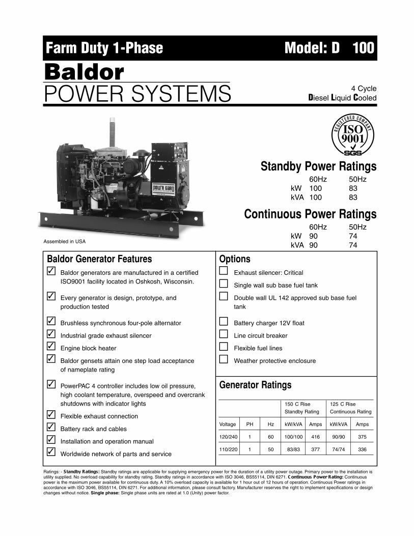
Baldor Generator Features� Baldor generators are manufactured in a certified
ISO9001 facility located in Oshkosh, Wisconsin.
� Every generator is design, prototype, andproduction tested
Brushless synchronous four-pole alternator
Industrial grade exhaust silencer
Engine block heater
Baldor gensets attain one step load acceptanceof nameplate rating
PowerPAC 4 controller includes low oil pressure,high coolant temperature, overspeed and overcrank shutdowns with indicator lights
Flexible exhaust connection
Installation and operation manual
Worldwide network of parts and service
Ratings: - Standby Ratings: Standby ratings are applicable for supplying emergency power for the duration of a utility power outage. Primary power to the installation isutility supplied. No overload capability for standby rating. Standby ratings in accordance with ISO 3046, BS55114, DIN 6271. C ontinuous Power Rating: Continuouspower is the maximum power available for continuous duty. A 10% overload capacity is available for 1 hour out of 12 hours of operation. Continuous Power ratings inaccordance with ISO 3046, BS55114, DIN 6271. For additional information, please consult factory. Manufacturer reserves the right to implement specifications or designchanges without notice. Single phase: Single phase units are rated at 1.0 (Unity) power factor.
Generator Ratings
150 � C Rise 125 � C Rise
Standby Rating Continuous Rating
Voltage PH Hz kW/kVA Amps kW/kVA Amps
120/240 1 60 100/100 416 90/90 375
110/220 1 50 83/83 377 74/74 336
OptionsExhaust silencer: Critical
� Single wall sub base fuel tank
� Double wall UL 142 approved sub base fuel tank
� Battery charger 12V float
� Line circuit breaker
� Flexible fuel lines
� Weather protective enclosure
4 CycleDiesel Liquid Cooled
Standby Power Ratings60Hz 50Hz
kW 100 83kVA 100 83
Continuous Power Ratings60Hz 50Hz
kW 90 74kVA 90 74
Farm Duty 1-Phase Model: D��100
BaldorPOWER SYSTEMS
�
�
Assembled in USA
��
��
��
��
��
��
��
��
��
�
Battery rack and cables
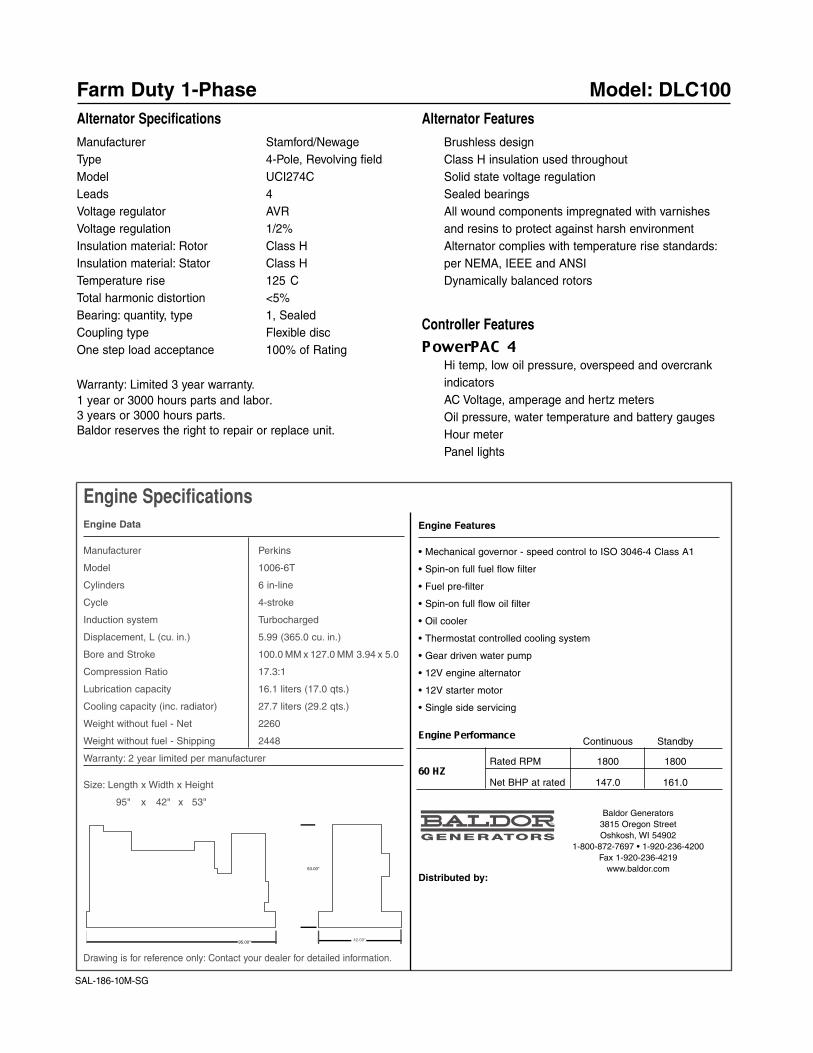
Engine SpecificationsEngine Data
Manufacturer Perkins
Model 1006-6T
Cylinders 6 in-line
Cycle 4-stroke
Induction system Turbocharged
Displacement, L (cu. in.) 5.99 (365.0 cu. in.)
Bore and Stroke 100.0 MM x 127.0 MM 3.94 x 5.0
Compression Ratio 17.3:1
Lubrication capacity 16.1 liters (17.0 qts.)
Cooling capacity (inc. radiator) 27.7 liters (29.2 qts.)
Weight without fuel - Net 2260
Weight without fuel - Shipping 2448
Warranty: 2 year limited per manufacturer
Size: Length x Width x Height
95" x 42" x 53"
Drawing is for reference only: Contact your dealer for detailed information.
Farm Duty 1-Phase Model: DLC100Alternator Specifications
Manufacturer Stamford/NewageType 4-Pole, Revolving fieldModel UCI274CLeads 4Voltage regulator AVRVoltage regulation 1/2%Insulation material: Rotor Class HInsulation material: Stator Class HTemperature rise 125 � CTotal harmonic distortion <5%Bearing: quantity, type 1, SealedCoupling type Flexible discOne step load acceptance 100% of Rating
Warranty: Limited 3 year warranty.
Alternator Features
Brushless designClass H insulation used throughoutSolid state voltage regulationSealed bearingsAll wound components impregnated with varnishesand resins to protect against harsh environmentAlternator complies with temperature rise standards:per NEMA, IEEE and ANSIDynamically balanced rotors
Controller Features
PowerPAC 4Hi temp, low oil pressure, overspeed and overcrankindicatorsAC Voltage, amperage and hertz metersOil pressure, water temperature and battery gaugesHour meterPanel lights
Engine Features
• Mechanical governor - speed control to ISO 3046-4 Class A1
• Spin-on full fuel flow filter
• Fuel pre-filter
• Spin-on full flow oil filter
• Oil cooler
• Thermostat controlled cooling system
• Gear driven water pump
• 12V engine alternator
• 12V starter motor
• Single side servicing
Engine PerformanceContinuous Standby
60 HZRated RPM 1800 1800
Net BHP at rated 147.0 161.0
Distributed by:
42.00"
53.00"
95.00"
1 year or 3000 hours parts and labor. 3 years or 3000 hours parts.Baldor reserves the right to repair or replace unit.
Baldor Generators3815 Oregon StreetOshkosh, WI 54902
1-800-872-7697 • 1-920-236-4200Fax 1-920-236-4219
www.baldor.com
SAL-186-10M-SG

Baldor Generator Features� Baldor generators are manufactured in a certified
ISO9001 facility located in Oshkosh, Wisconsin
� Every generator is design, prototype, andproduction tested
� Brushless synchronous four-pole alternator
� Industrial grade exhaust silencer
� Engine block heater
� Baldor gensets attain one step load acceptanceof nameplate rating
� PowerPAC 4 controller includes low oil pressure,high coolant temperature, overspeed and overcrank shutdowns with indicator lights
� Flexible exhaust connection
�� Installation and operation manual
� Worldwide network of parts and service
Ratings: - Standby Ratings: Standby ratings are applicable for supplying emergency power for the duration of a utility power outage. Primary power to the installation isutility supplied. No overload capability for standby rating. Standby ratings in accordance with ISO 3046, BS55114, DIN 6271. C ontinuous Power Rating: Continuouspower is the maximum power available for continuous duty. A 10% overload capacity is available for 1 hour out of 12 hours of operation. Continuous Power ratings inaccordance with ISO 3046, BS55114, DIN 6271. For additional information, please consult factory. Manufacturer reserves the right to implement specifications or designchanges without notice. Single phase: Single phase units are rated at 1.0 (Unity) power factor.
Generator Ratings
150 � C Rise 125 � C Rise
Standby Rating Continuous Rating
Voltage PH Hz kW/kVA Amps kW/kVA Amps
120/240 1 60 130/130 541 117/117 487
110/220 1 50 108/108 490 97/97 441
Options� Exhaust silencer: Critical
� Single wall sub base fuel tank
� Double wall UL 142 approved sub base fuel tank
� Battery charger 12V float
� Line circuit breaker
� Flexible fuel lines
� Weather protective enclosure
4 CycleDiesel Liquid Cooled
Standby Power Ratings60Hz 50Hz
kW 130 108kVA 130 108
Continuous Power Ratings60Hz 50Hz
kW 117 97kVA 117 97
Farm Duty 1-Phase Model: D��130
BaldorPOWER SYSTEMS
�
�
�
�
�
�
�
�
�
�
�
Assembled in USA
Battery rack and cables

Engine SpecificationsEngine Data
Manufacturer Perkins
Model 1006-6TA
Cylinders 6 in-line
Cycle 4-stroke
Induction system Turbocharged - aftercooled
Displacement, L (cu. in.) 5.99 (365.0 cu. in.)
Bore and Stroke 100.0 MM x 127.0 MM 3.94 x 5.0
Compression Ratio 17.3:1
Lubrication capacity 19.0 liters (20.0 qts.)
Cooling capacity (inc. radiator) 37.2 liters (39.3 qts.)
Weight without fuel - Net 2610
Weight without fuel - Shipping 3040
Warranty: 2 year limited per manufacturer
Size: Length x Width x Height
95" x 42" x 53"
Drawing is for reference only: Contact your dealer for detailed information.
Farm Duty 1-Phase Model: DLC130Alternator Specifications
Manufacturer Stamford/NewageType 4-Pole, Revolving fieldModel UCI274ELeads 4Voltage regulator AVRVoltage regulation 1/2%Insulation material: Rotor Class HInsulation material: Stator Class HTemperature rise 125 � CTotal harmonic distortion <5%Bearing: quantity, type 1, SealedCoupling type Flexible discOne step load acceptance 100% of Rating
Warranty: Limited 3 year warranty.
Alternator Features
Brushless designClass H insulation used throughoutSolid state voltage regulationSealed bearingsAll wound components impregnated with varnishesand resins to protect against harsh environmentAlternator complies with temperature rise standards:per NEMA, IEEE and ANSIDynamically balanced rotors
Controller Features
PowerPAC 4Hi temp, low oil pressure, overspeed and overcrankindicatorsAC Voltage, amperage and hertz metersOil pressure, water temperature and battery gaugesHour meterPanel lights
Engine Features
• Mechanical governor - speed control to ISO 3046-4 Class A1
• Spin-on full fuel flow filter
• Fuel pre-filter
• Spin-on full flow oil filter
• Oil cooler
• Thermostat controlled cooling system
• Gear driven water pump
• 12V engine alternator
• 12V starter motor
• Single side servicing
Engine PerformanceContinuous Standby
60 HZRated RPM 1800 1800
Net BHP at rated 188.0 206.5
Distributed by:
42.00"
53.00"
95.00"
1 year or 3000 hours parts and labor. 3 years or 3000 hours parts.Baldor reserves the right to repair or replace unit.
Baldor Generators3815 Oregon StreetOshkosh, WI 54902
1-800-872-7697 • 1-920-236-4200Fax 1-920-236-4219
www.baldor.com
SAL-187-10M-SG
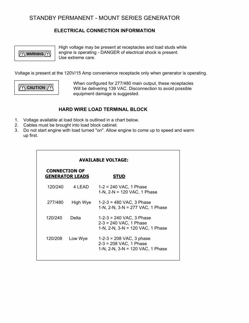
STANDBY PERMANENT - MOUNT SERIES GENERATOR ELECTRICAL CONNECTION INFORMATION
High voltage may be present at receptacles and load studs while engine is operating - DANGER of electrical shock is present.
Use extreme care. Voltage is present at the 120V/15 Amp convenience receptacle only when generator is operating. When configured for 277/480 main output, these receptacles Will be delivering 139 VAC. Disconnection to avoid possible
equipment damage is suggested. HARD WIRE LOAD TERMINAL BLOCK 1. Voltage available at load block is outlined in a chart below. 2. Cables must be brought into load block cabinet. 3. Do not start engine with load turned "on". Allow engine to come up to speed and warm up first.
AVAILABLE VOLTAGE: CONNECTION OF GENERATOR LEADS STUD 120/240 4 LEAD 1-2 = 240 VAC, 1 Phase 1-N, 2-N = 120 VAC, 1 Phase 277/480 High Wye 1-2-3 = 480 VAC, 3 Phase 1-N, 2-N, 3-N = 277 VAC, 1 Phase 120/240 Delta 1-2-3 = 240 VAC, 3 Phase 2-3 = 240 VAC, 1 Phase 1-N, 2-N, 3-N = 120 VAC, 1 Phase 120/208 Low Wye 1-2-3 = 208 VAC, 3 phase 2-3 = 208 VAC, 1 Phase 1-N, 2-N, 3-N = 120 VAC, 1 Phase
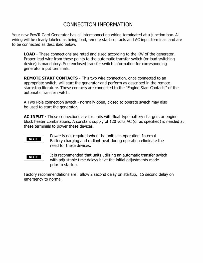
CONNECTION INFORMATION Your new Pow'R Gard Generator has all interconnecting wiring terminated at a junction box. All wiring will be clearly labeled as being load, remote start contacts and AC input terminals and are to be connected as described below.
LOAD - These connections are rated and sized according to the KW of the generator. Proper lead wire from these points to the automatic transfer switch (or load switching device) is mandatory. See enclosed transfer switch information for corresponding generator input terminals. REMOTE START CONTACTS - This two wire connection, once connected to an appropriate switch, will start the generator and perform as described in the remote start/stop literature. These contacts are connected to the "Engine Start Contacts" of the automatic transfer switch. A Two Pole connection switch - normally open, closed to operate switch may also be used to start the generator. AC INPUT - These connections are for units with float type battery chargers or engine block heater combinations. A constant supply of 120 volts AC (or as specified) is needed at these terminals to power these devices. Power is not required when the unit is in operation. Internal Battery charging and radiant heat during operation eliminate the need for these devices. It is recommended that units utilizing an automatic transfer switch with adjustable time delays have the initial adjustments made prior to startup. Factory recommendations are: allow 2 second delay on startup, 15 second delay on emergency to normal.
STANDBY PERMANENT MOUNT SERIES GENERATOR
GENERATOR MOUNTING REQUIREMENTS
The generator set must be secured to a solid surface, which is non-combustible. A concrete floor is typical of this application. Wood floors should be prepared in accordance with local and state requirements for the load, heat and fluids that will be encountered with operation of this generator set. This generator base shall be anchored to the concrete floor with minimum 3/8" anchors. We do not suggest use of secondary isolators between the base and the floor surface, as durometers vary and may affect the isolation properties of the standard generator mounts. Please note that it is not recommended by the manufacturer that this generator be operated without being permanently mounted to a concrete slab or similar application in accordance with your local and state regulations. We also recommend that the generator be located 3 to 5 feet away from any permanent structure such as walls, bushes, etc. Check with your local city hall for official requirements in your area. The generator should be level for proper operation. When mounted, the generator should be properly aligned and located in a well-ventilated place where the air temperature will not exceed 40OC or 104OF, and should be accessible for cleaning. An open type generator should not be located where there are abrasive or conductive dusts, corrosive gasses or fumes, or where excessive moisture, standing or dripping water may be encountered. Limit dust and dirt accumulation and assure a rodent-proof environment. A totally enclosed generator should be cleaned frequently to remove accumulated dust and dirt , which may cause overheating. A dimensional diagram to aid in mounting this model is included in your Bill of Materials / Technical Diagrams Packet. ENGINE COOLING REQUIREMENTS A sufficient flow of clean, cool air is required to support combustion and to dissipate the heat produced in the combustion process of an internal combustion engine. Approximately 60% of the heat value of fuel consumed by an engine will be disbursed to the cooling air and to the exhaust. All engines are either directly or indirectly cooled by air. The Air-Cooled Engine must transfer the excess heat directly to the air surrounding it. The heated air must then be directed away from the engine so it will not overheat. If the engine is situated in an open installation there should not be a cooling problem, but when the engine is installed in a building it is essential to provide: 1. Adequate control and evacuation of the heated cooling air. 2. An adequate and constant supply of incoming cooling air. 3. Adequate control and discharge of the engine's hot exhaust gases. 4. Adequate ventilation of the building when the engine shuts down.

ENGINE COOLING AIR The air, which will cool the engine, must be brought in from outside the building. A forced airflow of sufficient Cubic Feet per Minute (CFM) will prevent the incoming cooling air from mixing with the air inside the building and eventually overheating and damaging the engine. To do this requires that an exhaust fan of sufficient CFM be placed near the generator set to exhaust the heated cooling air and to also draw in cool external air. The cooling air intake should be located so that the cooling air will be brought in through this intake opening, travel across the generator set, and then be evacuated from the building via the exhaust fan. It is recommended that the cooling air intake have at least twice the cross-sectional opening area as the heating cooling air exhaust fan located near the generator set. It is also recommended that the air intake opening be located as close as possible to the same level as the top of the generator set. The exhaust fan must NOT be located where it could easily become blocked by leaves, snow, water, debris, etc… The cooling air intake opening of the building should be of sufficient size so as to not interfere with the cooling air intake airflow. It is recommended that the intake opening be no less than 3 times the cross sectional area of the exhaust fan opening. It is also recommended that this opening be located on a vertical plane so as to not easily become plugged with debris. If utilizing some type of covering over the intake opening (louvers, expanded metal, screening, etc…) it is very important that the combined total of the cross-sectional area openings be no less than 3 times the cross-sectional area of the exhaust fan opening. The heated cooling air coming off the engine must be directed, and evacuated out of the building. An exhaust fan of sufficient CFM will need to be used to achieve this end result. Regarding the exhaust fan size, remember that no heated cooling air must be allowed to accumulate inside the building. For air-cooled units of 8-12KW we recommend an exhaust fan of 2000 CFM. Location of the exhaust fan for the engine's heated cooling air is important. It must be located so that the heated cooling air evacuated from the building not be allowed to re-circulate back into the cooling air intake of the building or generator set. It is also important that it not be located where leaves, snow, water, debris, etc could easily block it… The exhaust fan should be located near the generator set on it's right or left side. If the unit has a side mounted muffler it is preferable to put the exhaust fan on this side. You must not position the exhaust fan so as to pull the incoming cooling air away from the cool air intake of either the engine or the generator end. The exhaust fan must be connected to the AC power terminals of the generator set so that when the generator set starts it will immediately engage to provide immediate cooling air flow. The fan will then stay engaged until the generator set stops.
It is important to keep any and all flammable objects or materials away from this generator set, the remote muffler and it's attached
piping, or any other potential hot component of the installation.
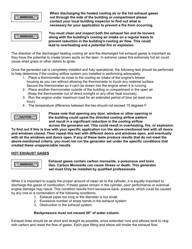
When discharging the heated cooling air or the hot exhaust gases out through the side of the building or compartment please contact your local building inspector to find out what is necessary for your application to prevent a fire from occurring. You must clean and inspect both the exhaust fan and its louvers along with the building's cooling air intake on a regular basis to
prevent reduction in the building's cooling air flow. This could lead to overheating and a potential fire or explosion.
The direction of the discharged heating cooling air and the discharged hot exhaust gases is important as they have the potential to create brown spots on the lawn. In extreme cases this extremely hot air could cause dried grass or other debris to ignite. Once the generator set is completely installed and fully operational, the following test should be performed to help determine if the cooling airflow system you installed is performing adequately. 1. Place a thermometer as close to the cooling air intake of the engine's blower housing as you can without allowing the thermometer to touch any material surface. Secure the thermometer so it can't be drawn into the engine when it is running. 2. Place another thermometer outside of the building or compartment in the open air (Keep the thermometer out of direct sunlight or any other heat sources). 3. Run the engine under maximum load for an extended period of time (at least one hour). 4. The temperature difference between the two should not exceed 15 degrees F.
Please note that opening any door, window or other opening in the building could upset the directed cooling airflow pattern
and result in a significant reduction in the cooling airflow across the generator set. This could result in overheating, fire, or explosion. To find out if this is true with your specific application run the above-mentioned test with all doors and windows closed. Then repeat this test with different doors and windows open, and eventually with all the windows and doors open. If any of these tests produce results that do not meet the above-mentioned criteria, you must not run the generator set under the specific conditions that created these unappreciable results. HOT EXHAUST GASES
Exhaust gases contain carbon monoxide, a poisonous and toxic Gas. Carbon Monoxide can cause illness or death. This generator
set must Only be installed by qualified professionals. While it is important to supply the proper amount of clean air to the cylinder, it is equally important to discharge the gases of combustion. If these gases remain in the cylinder, poor performance or eventual engine damage may result. This condition results from excessive back- pressure, which could be caused by any one or a combination of the following conditions: 1. Exhaust pipes too long or the diameter is too small. 2. Excessive number of sharp bends in the exhaust system. 3. Obstruction in the exhaust system.
Backpressure must not exceed 20" of water column. Exhaust lines should be as short and straight as possible, since extended runs and elbows tend to clog with carbon and resist the flow of gases. Each pipe fitting and elbow will hinder the exhaust flow.
If you are using a remote muffler it should be mounted as close to the engine as possible, since it will clog with carbon if it's operating temperature is too low. If you are using a remote muffler a flexible coupling of 12" or more must be installed between the exhaust line and the manifold to absorb the engine's vibration. However, a short, solid section of pipe between 6" and 8" long should be placed between the connection of the manifold and the flexible coupling. This nipple will reduce the possibility of the hot gases burning up the flexible coupling. Water is one of the by-products of combustion and will be present in the exhaust piping or muffler. This water must be kept from draining back into the engine. Slanting the horizontal section of the exhaust system piping downward slightly, away from the engine can do this. A water trap consisting of a tee extension with a drain cock should also be provided. This water trap should be located between the flex coupling and the muffler, but as close to the engine as possible on a horizontal section of the exhaust piping. It is also recommended that an exhaust rain cap be used whenever it is possible that rain could get into the system. This will help to prevent corrosion and damage to the exhaust system and engine. The exhaust system is subject to the engine's vibration and it must therefore be solidly secured to prevent unnecessary stress and the potential for breakage. The engine's exhaust system is the hottest component of the installation and extreme care and considerations must be given to it. Whenever possible the remote muffler should be located outside of the building or compartment. As much of the exhaust piping as possible should be located within the engine's heated cooling are exhaust flow. This will help to prevent the accumulation of radiant exhaust heat inside the building. In some cases, the idea of mounting the muffler outside the building conflicts with the idea of mounting the muffler close to the engine to prevent carbon buildup. In these cases it is best to mount the muffler near the engine and provide an air flow around the muffler to evacuate the muffler's radiant heat out of the compartment or building. However, the exhaust outlet must be extended outside of the building. Under no conditions shall the exhaust outlet be positioned so that the exhaust gases would be directed towards any openings or air entry routes (doors, windows, vents, etc...) of an occupied building. When discharging the hot exhaust gases out of the building do not direct them towards anything that could catch fire or explode. If the remote muffler cannot be located outside of the building or compartment, the next best option is to locate it in the engine's heated cooling air exhaust flow. It is extremely important that you do not allow the hot exhaust gases to re- circulate back into the engine's cooling air intake. It is important to keep any and all flammable objects or materials away from the generator set, the remote muffler and its attached piping, as well as any other potentially hot component of the installation.
When discharging the heated cooling air or the hot exhaust gases out through the side of the building please contact your local building inspector to find out what is necessary for your application to meet local building code requirements. Keep all fuel and its associated piping away from all components of the engine exhaust system.
Once the exhaust system is installed it should be inspected on a regular basis to assure there are no toxic exhaust gas leaks.
In some areas this inspection may be provided by your local public service. BUILDING VENTILATION As hot air rises you must provide some type of power ventilation at the highest possible point of the building to permit the accumulating hot air to escape. This will help to prevent engine damage and it will help to eliminate hot restart problems. An electric powered exhaust fan of sufficient size will satisfy this requirement. This fan must connect to the generator set in a manner similar to the building's main heated cooling air exhaust fan. Generator End Cooling Requirements The cooling air requirements for the generator end are very similar to the cooling air requirements for the engine. These requirements are: 1. An adequate and constant supply of cooling air. 2. Adequate control and evacuation of the heated cooling air. GENERATOR END COOLING AIR If the above exhaust fan sizing recommendation is followed there will be an adequate supply of cooling air for the generator end. Please remember to not position the exhaust fan so it will pull the incoming cooling air away from the cooling air intake of either the engine or generator end. It is important to keep any and all flammable objects or materials away from the generator set, the remote muffler and its attached piping, or any other potential hot component of the installation. When discharging the heated cooling air or the hot exhaust gases out through the side of the building please contact your local building inspector to find out what is necessary for your application to meet local building code requirements and to prevent fire from occurring. You must clean and inspect both the exhaust fan and its louvers along with the building's cooling air intake on a regular basis to prevent reduction in the building's cooling air flow. This could lead to overheating and a potential fire or explosion.

BUILDING VENTILATION As hot air rises you must provide some type of power ventilation at the highest possible point of the building to permit the accumulating hot air to escape. This will help to prevent engine damage and it will help to eliminate hot restart problems. An electric powered exhaust fan of sufficient size will satisfy this requirement. This fan must connect to the generator set in a manner similar to the building's main heated cooling air exhaust fan.
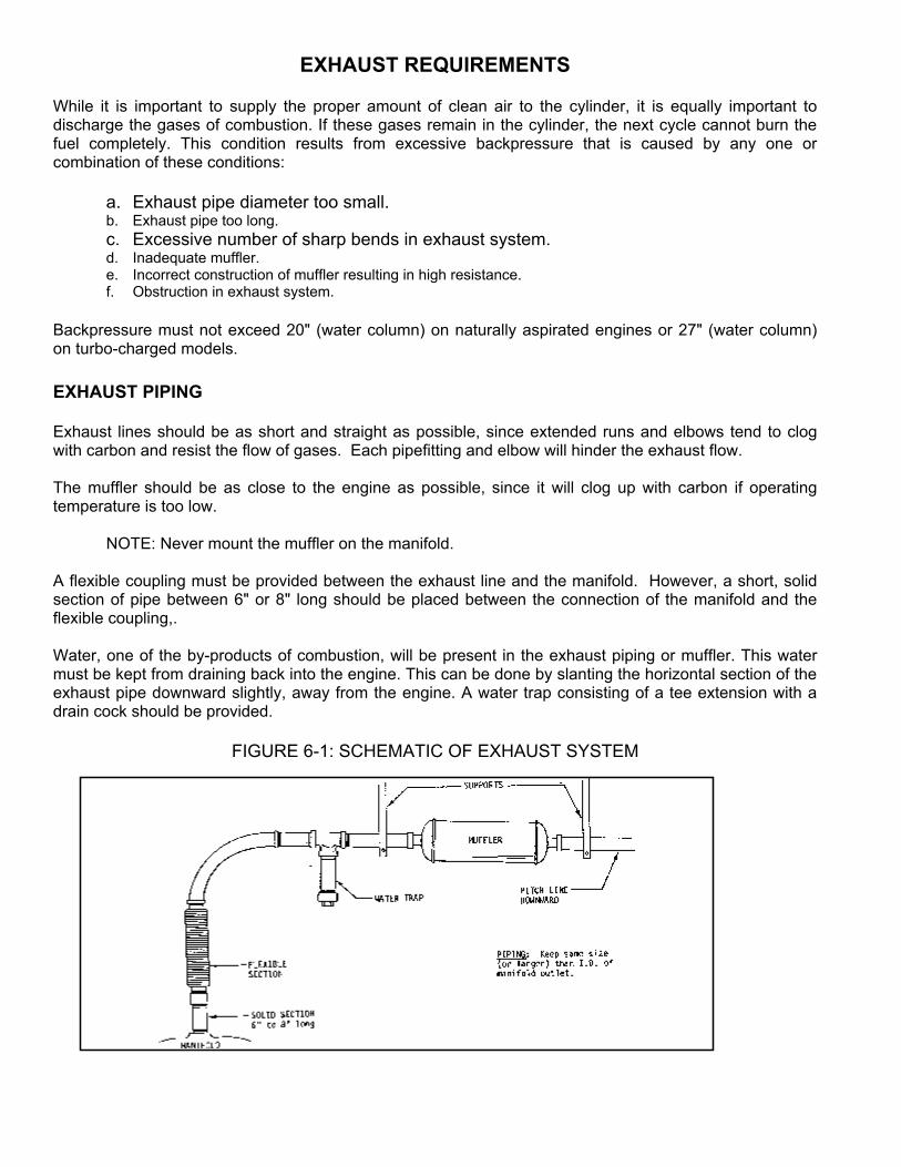
EXHAUST REQUIREMENTS While it is important to supply the proper amount of clean air to the cylinder, it is equally important to discharge the gases of combustion. If these gases remain in the cylinder, the next cycle cannot burn the fuel completely. This condition results from excessive backpressure that is caused by any one or combination of these conditions: a. Exhaust pipe diameter too small. b. Exhaust pipe too long. c. Excessive number of sharp bends in exhaust system. d. Inadequate muffler. e. Incorrect construction of muffler resulting in high resistance. f. Obstruction in exhaust system. Backpressure must not exceed 20" (water column) on naturally aspirated engines or 27" (water column) on turbo-charged models. EXHAUST PIPING Exhaust lines should be as short and straight as possible, since extended runs and elbows tend to clog with carbon and resist the flow of gases. Each pipefitting and elbow will hinder the exhaust flow. The muffler should be as close to the engine as possible, since it will clog up with carbon if operating temperature is too low. NOTE: Never mount the muffler on the manifold. A flexible coupling must be provided between the exhaust line and the manifold. However, a short, solid section of pipe between 6" or 8" long should be placed between the connection of the manifold and the flexible coupling,. Water, one of the by-products of combustion, will be present in the exhaust piping or muffler. This water must be kept from draining back into the engine. This can be done by slanting the horizontal section of the exhaust pipe downward slightly, away from the engine. A water trap consisting of a tee extension with a drain cock should be provided.
FIGURE 6-1: SCHEMATIC OF EXHAUST SYSTEM
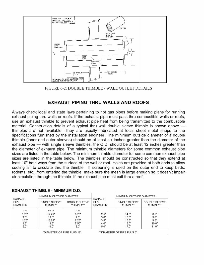
FIGURE 6-2: DOUBLE THIMBLE - WALL OUTLET DETAILS
EXHAUST PIPING THRU WALLS AND ROOFS
Always check local and state laws pertaining to hot gas pipes before making plans for running exhaust piping thru walls or roofs. If the exhaust pipe must pass thru combustible walls or roofs, use an exhaust thimble to prevent exhaust pipe heat from being transmitted to the combustible material. Construction details of a typical thru wall double sleeve thimble is shown above — thimbles are not available. They are usually fabricated at local sheet metal shops to the specifications furnished by the installation engineer. The minimum outside diameter of a double thimble (inner and outer sleeves) should be at least six inches greater than the diameter of the exhaust pipe — with single sleeve thimbles, the O.D. should be at least 12 inches greater than the diameter of exhaust pipe. The minimum thimble diameters for some common exhaust pipe sizes are listed in the table below. The minimum thimble diameter for some common exhaust pipe sizes are listed in the table below. The thimbles should be constructed so that they extend at least 10" both ways from the surface of the wall or roof. Holes are provided at both ends to allow cooling air to circulate thru the thimble. If screening is used on the outer end to keep birds, rodents, etc., from entering the thimble, make sure the mesh is large enough so it doesn’t impair air circulation through the thimble. If the exhaust pipe must exit thru a roof, EXHAUST THIMBLE - MINIMUM O.D.
MINIMUM OUTSIDE DIAMETER MINIMUM OUTSIDE DIAMETER EXHAUST PIPE DIAMETER
SINGLE SLEEVE THIMBLE*
DOUBLE SLEEVE THIMBLE**
EXHAUST PIPE DIAMETER
SINGLE SLEEVE THIMBLE*
DOUBLE SLEEVE THIMBLE**
0.5" 0.75" 1.0"
1.25" 1.5" 2.0"
12.5" 12.75" 13.0"
13.25" 13.5" 14.0"
6.5" 6.75" 7.0"
7.25" 7.50" 8.0"
2.5" 3.0" 3.5" 4.0" 5.0"
14.5" 15.0" 15.5" 16.0" 17.0"
8.5" 9.0" 9.5"
10.0" 11.0"
*DIAMETER OF PIPE PLUS 12". **DIAMETER OF PIPE PLUS 6"
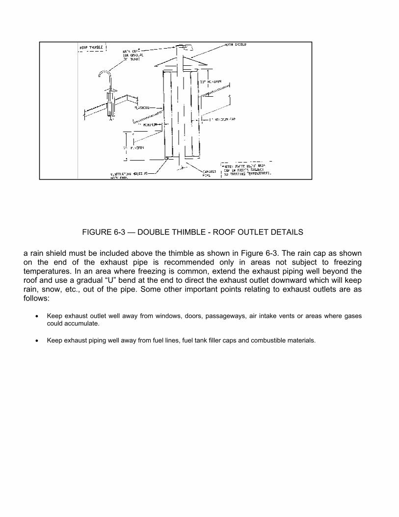
FIGURE 6-3 — DOUBLE THIMBLE - ROOF OUTLET DETAILS
a rain shield must be included above the thimble as shown in Figure 6-3. The rain cap as shown on the end of the exhaust pipe is recommended only in areas not subject to freezing temperatures. In an area where freezing is common, extend the exhaust piping well beyond the roof and use a gradual “U” bend at the end to direct the exhaust outlet downward which will keep rain, snow, etc., out of the pipe. Some other important points relating to exhaust outlets are as follows:
Keep exhaust outlet well away from windows, doors, passageways, air intake vents or areas where gases could accumulate.
Keep exhaust piping well away from fuel lines, fuel tank filler caps and combustible materials.

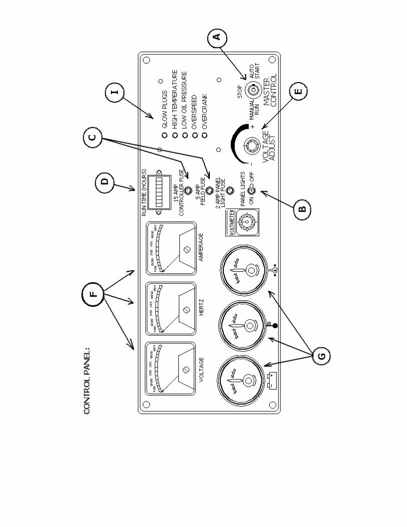
CONTROL PANEL OPERATION
AND FUNCTION A. MASTER CONTROL SWITCH - This switch controls the starting and stopping of the engine via the
engine control logic circuitry. With this switch in the “Manual” mode, the engine will start and run immediately after a 10 - 20 second time delay.
CAUTION: Please note that once the engine has been told to start, the gen set should be treated as though it is operational, even though the start delay has not yet allowed the engine to crank.
With this switch in the “Automatic” mode, the engine can be started and stopped from a remote contact. (Standard switch, transfer switch, etc.) There is a time delay, to cool down, of 60-90 seconds when the unit is shut down from the remote contacts while the Master Control Switch is in the “Automatic Mode.
With this switch in the “Off” position, the engine will immediately stop. The position must also be
utilized to clear fault shut-down conditions. B. PANEL LIGHTS - By turning on the panel light switch, the panel lights will be energized and will
illuminate the control panel. The fuse next to the switch is to protect this circuit from damage due to excessive current.
C. FIELD AND CONTROLLER FUSES - These fuses protect the internal workings of the generator set. D. GAUGES - These gauges monitor some of the more critical operating parameters of the engine as
well as the run time of the generator set. The Voltmeter displays the charging rate that is currently being produced by the engine’s alternator to
facilitate the charging of the battery. This gauge should normally be above 12.5V whenever the unit is running. If you ever notice the gauge is reading below 12V while the engine is running please contact the service department at Pow’R Gard Generator Corporation.
The Temperature Gauge monitors and displays the operating temperature of the engines coolant. The
point at which a fault shut-down will occur is 230OF. The Oil Pressure Gauge displays and monitors the current operating pressure of the engine’s oil
system. The trip point at which a fault shutdown will occur is 15 PSI or below. Fuel level is checked at the tank fill, inside the generator.
The Hour Meter accumulates and displays the total running time of the generator set. E. VOLTAGE ADJUST - The rheostat allows the user to “fine tune” the generator set’s voltage output. It
is normally used to adjust output voltage after switching the output of the generator set to a different voltage.
F. METERS - These meters monitor and display the current operating parameters of the generator set. The Voltmeter monitors and displays the current operating AC output of the generator set. The Hertz Meter monitors and displays the current operating frequency of the generator set. The Ammeter monitors and displays the amount of current that is being delivered by the generator
set. This meter works in conjunction with the Ammeter Switch (Item G) in determining which output leg to monitor.
G. AMMETER SWITCH - The switch allows the user to switch between L1, L2 and L3 to monitor the
current in each output leg to monitor. H. PANEL LIGHT - By turning on the panel light switch, the panel lights ( Not pictured on diagram) will
be energized and will illuminate the control panel. They will also illuminate when a fault condition or a warning condition develops. I - SYSTEM FAULT INDICATORS - These lights will come on when a fault condition or a warning
condition develops. The “Low Oil Pressure” light will come on when the engine’s oil pressure drops below 15 PSI. This
condition will trigger a fault shut-down and the unit will stop. The “Over-crank” light will come on when the engine has failed to start after four attempted crank
cycles. Each crank cycle consists of a 12 second time period followed by a 12 second rest time period. The “Over-speed” light will come on when the engine’s operating speed rises above it’s normal
operating parameters. This condition will trigger a fault shut-down and the engine will stop. High Temperature light will come on when the engine’s operating temperature exceeds the safety set-
point.
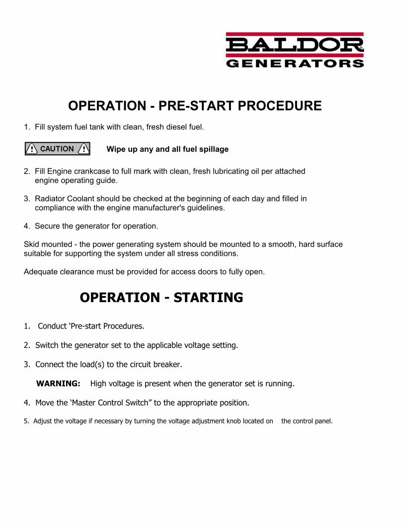
OPERATION - PRE-START PROCEDURE 1. Fill system fuel tank with clean, fresh diesel fuel.
Wipe up any and all fuel spillage 2. Fill Engine crankcase to full mark with clean, fresh lubricating oil per attached engine operating guide. 3. Radiator Coolant should be checked at the beginning of each day and filled in compliance with the engine manufacturer's guidelines. 4. Secure the generator for operation. Skid mounted - the power generating system should be mounted to a smooth, hard surface suitable for supporting the system under all stress conditions. Adequate clearance must be provided for access doors to fully open.
OPERATION - STARTING
1. Conduct ‘Pre-start Procedures. 2. Switch the generator set to the applicable voltage setting. 3. Connect the load(s) to the circuit breaker. WARNING: High voltage is present when the generator set is running. 4. Move the ‘Master Control Switch” to the appropriate position. 5. Adjust the voltage if necessary by turning the voltage adjustment knob located on the control panel.
OPERATION The Prime mover utilized in this power generating system is controlled via an engine control module. Starting is accomplished by commanding the control to "start" the engine. This command can be given by a number of controls; The operator control mounted on the front panel. The remote controls via the transfer switch or remote start terminal. Initially, the system may be started and operated by placing the operation control in the "manual" position. To cease operation, return the switch to the "off" position. Clear unit of all loose objects and perform all "pre- start" procedures before operating generator system. ENGINE CONTROL MODULE The Engine Control Module (E.C.M.) is a microprocessor based module that monitors the control and safety inputs and provides all the required START and STOP functions automatically. The following front panel controls and instruments are wired into the microprocessor through the E.C.M. terminal blocks: 1. RUN / OFF / AUTO SWITCH A. "RUN" - run position causes the generator set to start and run immediately. B. "AUTO" - auto position allows unit to be controlled via any remote single-pole "dry"
contact (transfer switch, etc.). Contact closure causes the unit to start and run, while contact opening causes unit to shut down after a preset cool down period.
C. "OFF" - unit operation is terminated. 2. LAMP TEST A. Push button energizes all alarm lights simultaneously. This feature is disabled with the
Run / stop / auto switch in the "stop" position and has no other effect on unit operation.
SAFETY INPUTS
1. Low Oil Pressure Shut-down- (LOP) Monitoring of oil pressure begins for a preset time after unit starts and remains in effect until unit
is shut down (except as noted in "loss of frequency input". The LOP signal is derived from an oil pressure switch gauge mounted on the control panel.
2. High Temperature Shutdown (HT) The engine temperature monitoring begins immediately with the start signal. However, if engine
temperature is excessive prior to start (i.e. heat soak after shutdown), the unit is permitted to start. The High temperature condition is permitted to exist for up to 60 seconds after the unit is running before shutdown when alarm occurs. If the excessive temperature condition is corrected within that time period, the HT circuit reverts to normal monitoring. The HT signal is derived from a monitoring device located on the prime mover.
3. Overspeed Adjustment (OS) - Over Frequency Overspeed protection is provided by a frequency sensing network within the controller. The trip
point of the frequency network is adjustable via a rheostat located on the top of the controller at the right hand side. Clockwise (CW) rotation increases the trip frequency and, thereby, raises the shutdown speed.
CRANKING CONTROL 1. Overcrank Protection This feature provides a preset second crank cycle. Failure of the engine to start by the end of the
crank period results in an "overcrank" shutdown and alarm indication. 2. Cranking Disconnect Adjustment (CDS Adjustment) The cranking disconnect signal is obtained by a frequency network within the controller. The trip
point of the frequency network is not adjustable. LOSS OF FREQUENCY Internal protection against loss of frequency input to the cranking disconnect circuit is programmed in after the unit has started normally. In the event the frequency goes to zero (engine runs out of fuel, frequency signal source fails, etc.) the LOP shutdown circuit is bypassed and a 12-second wait period is initiated. If frequency returns within this time period, LOP monitoring resumes and operation continues normally. If frequency has not returned at the end of this time period, the engine oil pressure status is observed to determine whether the engine is actually running or stopped. If the engine has stopped (i.e. air in fuel, etc.) the cranking cycle will begin in an effort to restart the engine. If the engine has not stopped (loss of input signal, etc.) the unit is shut down with an "overcrank" indication and alarm. "Overcrank" indication can mean a loss of crank-disconnect signal during the previous run period. Attempting to restart the engine with no crank- disconnect can destroy the starter motor, which can cause serious personal injury. This is of particular note since the tendency is to pursue only cranking and start related faults. The cranking disconnect signal source is a key component in this system and must be checked out thoroughly whenever an "overcrank" shutdown occurs. The controller does not provide protection against loss of signal during
startup. A shutdown with alarm, due to any of the above conditions, will prevent any subsequent operation of the generator set. The run-stop-auto selector switch on the control panel must be momentarily placed in the "stop" position to reset these functions.
If a dead battery is suspected, remove controller fuse, Replace with new battery and attempt starting. Damage to engine control may result from jump- starting.
TROUBLESHOOTING - GENERATOR As with any machine, trouble may develop in electrical generators. It may be due to long service or neglect of regular maintenance. Servicing, and checking. Should trouble develop, the following instructions will be helpful in tracing the cause and making repairs. SPEED DEVITIONS: The generator speed should be maintained at rated nameplate speed. The frequency and voltage of the generator output depends on speed. If the generator runs slower than rated speed, the voltage will drop off.
NO VOLTAGE
CAUSE CHECK AND REMEDY
Loss of residual magnetism in Flash Field. exciter field poles.
Open in stator windings Check for continuity in windings. Return to factory for
repair if open
Open or short in rotating rectifiers. Check rectifiers.
Short Circuited. Clear lead to restore voltage build-up.
Open in alternator field Check for continuity and return rotor to factory for repair if field coils are open.
Shorted exciter armature Check for short and replace if faulty.
Shorted leads between exciter Test and repair armature and generator field.
LOW VOLTAGE
CAUSE CHECK AND REMEDY
Excessive load. Reduce load. With 3 phase generators, the load on each leg should be as evenly balanced as possible and should not exceed the rated current on any leg.
Low Speed. Check engine for malfunction or system for overload.
Line loss. Increase size of line lead wire.
LOW VOLTAGE (Continued)
CAUSE CHECK AND REMEDY
High resistance connections- Make better connection electrically and Connections will be warm or hot mechanically.
Shorted field. Test field coils for possible short by checking
resistance with an ohmmeter or resistance bridge. Return rotor assembly to factory for repair if alternator field coils are shorted.
Low power factor Reduce inductive (motor) load. Some AC motors
Draw approximately the same current regardless of load. Do not use motors of larger horsepower rating than is necessary to carry the mechanical load.
FLUCTUATING VOLTAGE (May be indicated by flickering lights.)
CAUSE CHECK AND REMEDY
Irregular speed of engine. Check engine for malfunction or load for fluctuation.
Fluctuating speed. Stabilize load. The addition of a lamp load (resistance
load) may compensate partially for load changes caused by intermittent motor operation. Do not overload.
Loose terminal or load connections. Make better connection mechanically and electrically.
Defective bearing causing uneven air gap. Replace worn bearing.
HIGH VOLTAGE
CAUSE CHECK AND REMEDY
Excessive speed. Check engine for malfunction.
OVERHEATING
CAUSE CHECK AND REMEDY
Generator overloaded. Reduce load. (Check with ammeter and compare with nameplate rating.)
Clogged ventilating screens. Clean air passages.
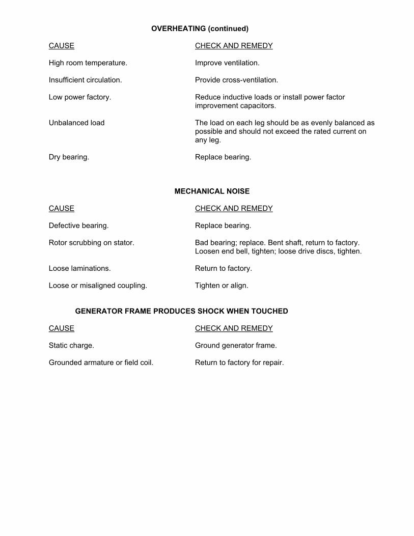
OVERHEATING (continued)
CAUSE CHECK AND REMEDY
High room temperature. Improve ventilation.
Insufficient circulation. Provide cross-ventilation.
Low power factory. Reduce inductive loads or install power factor improvement capacitors.
Unbalanced load The load on each leg should be as evenly balanced as
possible and should not exceed the rated current on any leg.
Dry bearing. Replace bearing.
MECHANICAL NOISE
CAUSE CHECK AND REMEDY
Defective bearing. Replace bearing.
Rotor scrubbing on stator. Bad bearing; replace. Bent shaft, return to factory. Loosen end bell, tighten; loose drive discs, tighten.
Loose laminations. Return to factory.
Loose or misaligned coupling. Tighten or align. GENERATOR FRAME PRODUCES SHOCK WHEN TOUCHED
CAUSE CHECK AND REMEDY
Static charge. Ground generator frame.
Grounded armature or field coil. Return to factory for repair.
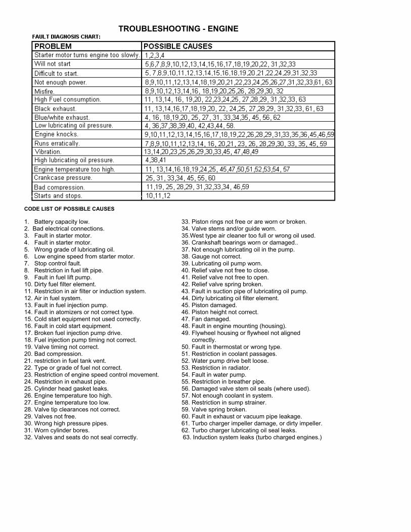
TROUBLESHOOTING - ENGINE
CODE LIST OF POSSIBLE CAUSES 1. Battery capacity low. 33. Piston rings not free or are worn or broken. 2. Bad electrical connections. 34. Valve stems and/or guide worn. 3. Fault in starter motor. 35.West type air cleaner too full or wrong oil used. 4. Fault in starter motor. 36. Crankshaft bearings worn or damaged.. 5. Wrong grade of lubricating oil. 37. Not enough lubricating oil in the pump. 6. Low engine speed from starter motor. 38. Gauge not correct. 7. Stop control fault. 39. Lubricating oil pump worn. 8. Restriction in fuel lift pipe. 40. Relief valve not free to close. 9. Fault in fuel lift pump. 41. Relief valve not free to open. 10. Dirty fuel filter element. 42. Relief valve spring broken. 11. Restriction in air filter or induction system. 43. Fault in suction pipe of lubricating oil pump. 12. Air in fuel system. 44. Dirty lubricating oil filter element. 13. Fault in fuel injection pump. 45. Piston damaged. 14. Fault in atomizers or not correct type. 46. Piston height not correct. 15. Cold start equipment not used correctly. 47. Fan damaged. 16. Fault in cold start equipment. 48. Fault in engine mounting (housing). 17. Broken fuel injection pump drive. 49. Flywheel housing or flywheel not aligned 18. Fuel injection pump timing not correct. correctly. 19. Valve timing not correct. 50. Fault in thermostat or wrong type. 20. Bad compression. 51. Restriction in coolant passages. 21. restriction in fuel tank vent. 52. Water pump drive belt loose. 22. Type or grade of fuel not correct. 53. Restriction in radiator. 23. Restriction of engine speed control movement. 54. Fault in water pump. 24. Restriction in exhaust pipe. 55. Restriction in breather pipe. 25. Cylinder head gasket leaks. 56. Damaged valve stem oil seals (where used). 26. Engine temperature too high. 57. Not enough coolant in system. 27. Engine temperature too low. 58. Restriction in sump strainer. 28. Valve tip clearances not correct. 59. Valve spring broken. 29. Valves not free. 60. Fault in exhaust or vacuum pipe leakage. 30. Wrong high pressure pipes. 61. Turbo charger impeller damage, or dirty impeller. 31. Worn cylinder bores. 62. Turbo charger lubricating oil seal leaks. 32. Valves and seats do not seal correctly. 63. Induction system leaks (turbo charged engines.)
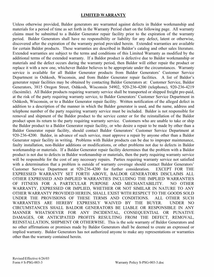
LIMITED WARRANTY Unless otherwise provided, Baldor generators are warranted against defects in Baldor workmanship and materials for a period of time as set forth in the Warranty Period chart on the following page. All warranty claims must be submitted to a Baldor Generator repair facility prior to the expiration of the warranty period. Baldor Generators shall have no responsibility or liability for any defect, latent or otherwise, discovered after the expiration of the warranty period provided herein. Extended warranties are available for certain Baldor products. These warranties are described in Baldor’s catalog and other sales literature. Extended warranties are subject to the terms and conditions of this Limited Warranty as modified by the additional terms of the extended warranty. If a Baldor product is defective due to Baldor workmanship or materials and the defect occurs during the warranty period, then Baldor will either repair the product or replace it with a new one, whichever Baldor believes to be appropriate under the circumstances. Warranty service is available for all Baldor Generator products from Baldor Generators’ Customer Service Department in Oshkosh, Wisconsin, and from Baldor Generator repair facilities. A list of Baldor’s generator repair facilities may be obtained by contacting Baldor Generators at: Customer Service, Baldor Generators, 3815 Oregon Street, Oshkosh, Wisconsin 54902, 920-236-4200 (telephone), 920-236-4219 (facsimile). All Baldor products requiring warranty service shall be transported or shipped freight pre-paid, at the risk of the party requiring warranty service, to Baldor Generators’ Customer Service Department in Oshkosh, Wisconsin, or to a Baldor Generator repair facility. Written notification of the alleged defect in addition to a description of the manner in which the Baldor generator is used, and the name, address and telephone number of the party requiring warranty service must be included. Baldor is not responsible for removal and shipment of the Baldor product to the service center or for the reinstallation of the Baldor product upon its return to the party requiring warranty service. Customers who are unable to take or ship the Baldor product to a Baldor Generator repair facility, or who desire a repair to be made by other than a Baldor Generator repair facility, should contact Baldor Generators’ Customer Service Department at 920-236-4200. Baldor, in advance of such service, must approve a repair by anyone other than a Baldor Generator repair facility in writing. Problems with Baldor products can be due to improper maintenance, faulty installation, non-Baldor additions or modifications, or other problems not due to defects in Baldor workmanship or materials. If a Baldor Generator repair facility determines that the problem with a Baldor product is not due to defects in Baldor workmanship or materials, then the party requiring warranty service will be responsible for the cost of any necessary repairs. Parties requiring warranty service not satisfied with a determination that a problem is outside of warranty coverage should contact Baldor Generators’ Customer Service Department at 920-236-4200 for further consideration. EXCEPT FOR THE EXPRESSED WARRANTY SET FORTH ABOVE, BALDOR GENERATORS DISCLAIMS ALL OTHER EXPRESSED AND IMPLIED WARRANTIES INCLUDING THE IMPLIED WARRANTIES OF FITNESS FOR A PARTICULAR PURPOSE AND MECHANTABILITY. NO OTHER WARRANTY, EXPRESSED OR IMPLIED, WHETHER OR NOT SIMILAR IN NATURE TO ANY OTHER WARRANTY PROVIDED HEREIN, SHALL EXIST WITH RESPECT TO THE GOODS SOLD UNDER THE PROVISIONS OF THESE TERMS AND CONDITIONS. ALL OTHER SUCH WARRANTIES ARE HEREBY EXPRESSLY WAIVED BY THE BUYER. UNDER NO CIRCUMSTANCES SHALL BALDOR GENERATORS BE LIABLE OR RESPONSIBLE IN ANY MANNER WHATSOEVER FOR ANY INCIDENTAL, CONSEQUENTIAL OR PUNATIVE DAMAGES, OR ANTICIPATED PROFITS RESULTING FROM THE DEFECT, REMOVAL, REINSTALLATION, SHIPMENT OR OTHERWISE. This is the sole warranty of Baldor Generators and no other affirmations or promises made by Baldor Generators shall be deemed to create an expressed or implied warranty. Baldor Generators has not authorized anyone to make any representations or warranties other than the warranty contained herein.
Revised\Effective 6/26/03 Form # S-PSG-003-3 Warranty Policy S-PSG-003-3.doc
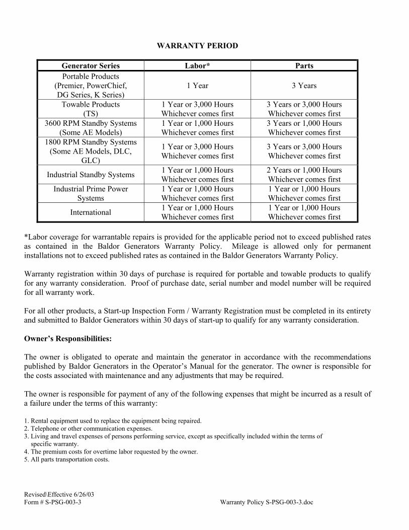
WARRANTY PERIOD
Generator Series Labor* Parts Portable Products
(Premier, PowerChief, DG Series, K Series)
1 Year 3 Years
Towable Products (TS)
1 Year or 3,000 Hours Whichever comes first
3 Years or 3,000 Hours Whichever comes first
3600 RPM Standby Systems (Some AE Models)
1 Year or 1,000 Hours Whichever comes first
3 Years or 1,000 Hours Whichever comes first
1800 RPM Standby Systems (Some AE Models, DLC,
GLC)
1 Year or 3,000 Hours Whichever comes first
3 Years or 3,000 Hours Whichever comes first
Industrial Standby Systems 1 Year or 1,000 Hours Whichever comes first
2 Years or 1,000 Hours Whichever comes first
Industrial Prime Power Systems
1 Year or 1,000 Hours Whichever comes first
1 Year or 1,000 Hours Whichever comes first
International 1 Year or 1,000 Hours Whichever comes first
1 Year or 1,000 Hours Whichever comes first
*Labor coverage for warrantable repairs is provided for the applicable period not to exceed published rates as contained in the Baldor Generators Warranty Policy. Mileage is allowed only for permanent installations not to exceed published rates as contained in the Baldor Generators Warranty Policy. Warranty registration within 30 days of purchase is required for portable and towable products to qualify for any warranty consideration. Proof of purchase date, serial number and model number will be required for all warranty work. For all other products, a Start-up Inspection Form / Warranty Registration must be completed in its entirety and submitted to Baldor Generators within 30 days of start-up to qualify for any warranty consideration. Owner’s Responsibilities: The owner is obligated to operate and maintain the generator in accordance with the recommendations published by Baldor Generators in the Operator’s Manual for the generator. The owner is responsible for the costs associated with maintenance and any adjustments that may be required. The owner is responsible for payment of any of the following expenses that might be incurred as a result of a failure under the terms of this warranty: 1. Rental equipment used to replace the equipment being repaired. 2. Telephone or other communication expenses. 3. Living and travel expenses of persons performing service, except as specifically included within the terms of specific warranty. 4. The premium costs for overtime labor requested by the owner. 5. All parts transportation costs.
Revised\Effective 6/26/03 Form # S-PSG-003-3 Warranty Policy S-PSG-003-3.doc
Limitations: Baldor Generators is not responsible for the repair of generators required because of normal wear, accident, misuse, abuse, improper installation, lack of maintenance, unauthorized modifications or improper storage. Normal Wear: This warranty will not cover repair where normal use has exhausted the life of a part or generator. It should be remembered that the service life of any generator is dependent on the care it receives and the conditions under which it has to operate. Some applications are very often used in dusty or dirty conditions, which can cause what appears to be excessive wear. Such wear, when caused by dirt, dust, grit or other abrasive material, which has entered the generator because of improper maintenance, is not covered by Warranty. For all product lines, the engine manufacturer warrants engine systems. Contact Baldor Generators for current engine warranties.
3815 Oregon Street • Oshkosh, Wisconsin 54902 Phone: (920) 236-4200 • 800-872-7697 • Fax: (920) 236-4219
www.baldor.com
Revised\Effective 6/26/03 Form # S-PSG-003-3 Warranty Policy S-PSG-003-3.doc
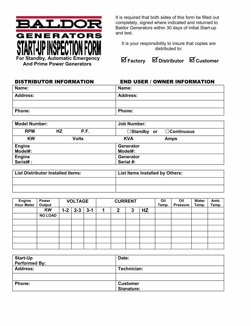
For Standby, Automatic Emergency And Prime Power Generators
It is required that both sides of this form be filled out completely, signed where indicated and returned to Baldor Generators within 30 days of initial Start-up and test.
It is your responsibility to insure that copies are distributed to:
Factory Distributor Customer
DISTRIBUTOR INFORMATION END USER / OWNER INFORMATION Name: Name: Address: Address: Phone: Phone: Model Number: Job Number: RPM HZ P.F. Standby or Continuous KW Volts KVA Amps Engine Model#:
Generator Model#:
Engine Serial# :
Generator Serial #:
List Distributor Installed Items: List Items Installed by Others:
Engine Hour Meter
Power Output
VOLTAGE CURRENT Oil Temp.
Oil Pressure
Water Temp.
Amb. Temp.
KW 1-2 2-3 3-1 1 2 3 HZ NO LOAD Start-Up Performed By:
Date:
Address: Technician: Phone: Customer
Signature:
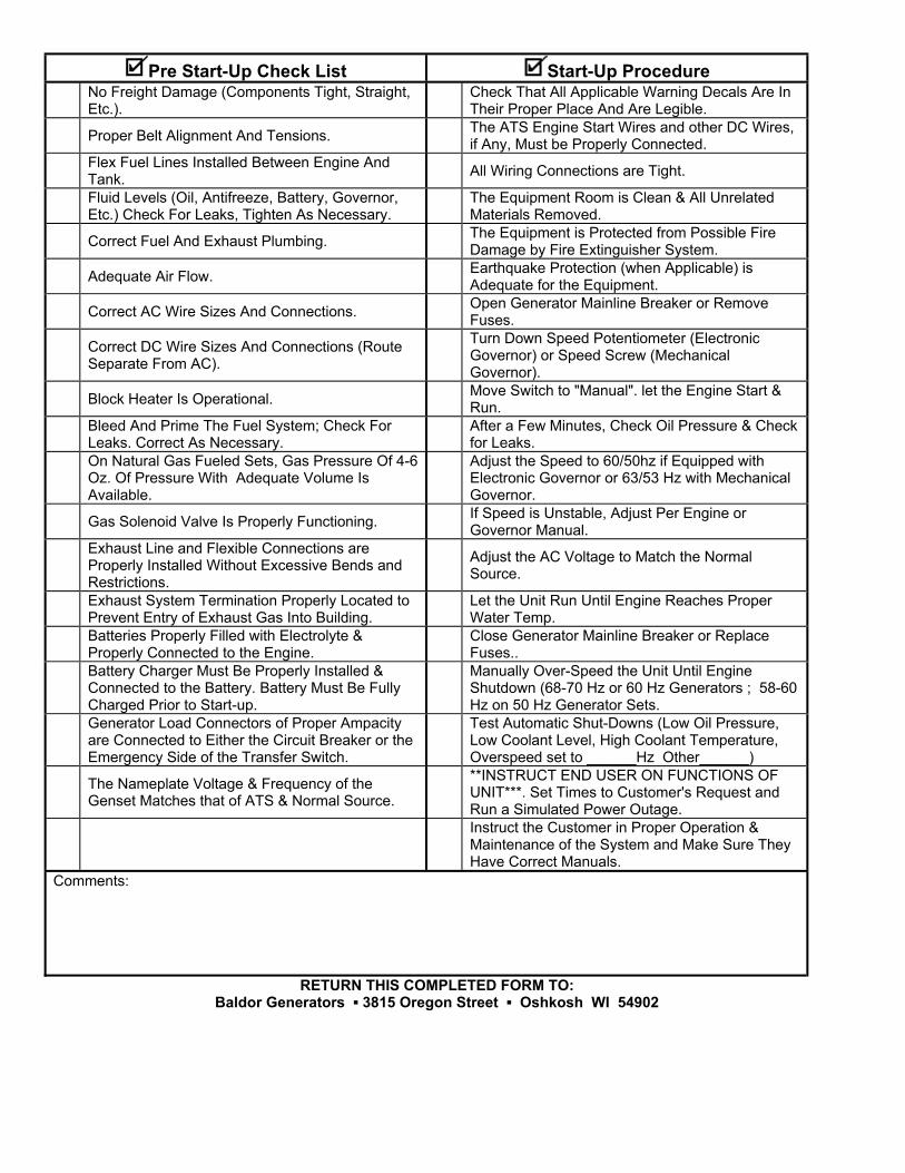
Pre Start-Up Check List Start-Up Procedure No Freight Damage (Components Tight, Straight,
Etc.). Check That All Applicable Warning Decals Are In
Their Proper Place And Are Legible. Proper Belt Alignment And Tensions. The ATS Engine Start Wires and other DC Wires,
if Any, Must be Properly Connected. Flex Fuel Lines Installed Between Engine And
Tank. All Wiring Connections are Tight.
Fluid Levels (Oil, Antifreeze, Battery, Governor, Etc.) Check For Leaks, Tighten As Necessary.
The Equipment Room is Clean & All Unrelated Materials Removed.
Correct Fuel And Exhaust Plumbing. The Equipment is Protected from Possible Fire Damage by Fire Extinguisher System.
Adequate Air Flow. Earthquake Protection (when Applicable) is Adequate for the Equipment.
Correct AC Wire Sizes And Connections. Open Generator Mainline Breaker or Remove Fuses.
Correct DC Wire Sizes And Connections (Route Separate From AC).
Turn Down Speed Potentiometer (Electronic Governor) or Speed Screw (Mechanical Governor).
Block Heater Is Operational. Move Switch to "Manual". let the Engine Start & Run.
Bleed And Prime The Fuel System; Check For Leaks. Correct As Necessary.
After a Few Minutes, Check Oil Pressure & Check for Leaks.
On Natural Gas Fueled Sets, Gas Pressure Of 4-6 Oz. Of Pressure With Adequate Volume Is Available.
Adjust the Speed to 60/50hz if Equipped with Electronic Governor or 63/53 Hz with Mechanical Governor.
Gas Solenoid Valve Is Properly Functioning. If Speed is Unstable, Adjust Per Engine or Governor Manual.
Exhaust Line and Flexible Connections are Properly Installed Without Excessive Bends and Restrictions.
Adjust the AC Voltage to Match the Normal Source.
Exhaust System Termination Properly Located to Prevent Entry of Exhaust Gas Into Building.
Let the Unit Run Until Engine Reaches Proper Water Temp.
Batteries Properly Filled with Electrolyte & Properly Connected to the Engine.
Close Generator Mainline Breaker or Replace Fuses..
Battery Charger Must Be Properly Installed & Connected to the Battery. Battery Must Be Fully Charged Prior to Start-up.
Manually Over-Speed the Unit Until Engine Shutdown (68-70 Hz or 60 Hz Generators ; 58-60 Hz on 50 Hz Generator Sets.
Generator Load Connectors of Proper Ampacity are Connected to Either the Circuit Breaker or the Emergency Side of the Transfer Switch.
Test Automatic Shut-Downs (Low Oil Pressure, Low Coolant Level, High Coolant Temperature, Overspeed set to ______Hz Other______)
The Nameplate Voltage & Frequency of the Genset Matches that of ATS & Normal Source.
**INSTRUCT END USER ON FUNCTIONS OF UNIT***. Set Times to Customer's Request and Run a Simulated Power Outage.
Instruct the Customer in Proper Operation & Maintenance of the System and Make Sure They Have Correct Manuals.
Comments:
RETURN THIS COMPLETED FORM TO: Baldor Generators 3815 Oregon Street Oshkosh WI 54902

3518 Oregon Street Oshkosh WI 54902 Phone: 920-239-4200 Fax: 920-236-4219
Baldor Generators firmly believes proper installation along with proper maintenance are critical factors in assuring proper, dependable, safe and long term operation. The checklist was developed for making sure your installation is correct to help achieve these goals.
If you have any questions about this checklist, please contact the Product Support Group at 920-236-4200.
Many measurements, adjustments and procedures mentioned in this checklist could cause damage, injury or even death if not performed properly. Only qualified, experienced individuals may perform these measurements, adjustments and procedures. When completed, please mail this checklist to Baldor Generators.
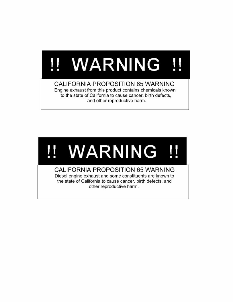
CALIFORNIA PROPOSITION 65 WARNING
Engine exhaust from this product contains chemicals known to the state of California to cause cancer, birth defects, and other reproductive harm.
CALIFORNIA PROPOSITION 65 WARNING Diesel engine exhaust and some constituents are known to the state of California to cause cancer, birth defects, and other reproductive harm.
Service is just a phone call away:
800-872-7697
www.baldor.com/products/generators.asp
3815 Oregon Street Oshkosh WI 54902
Phone: (920) 236-4200 Fax: (920) 236-4219