Embed Size (px)
Citation preview

STANDART APPLICATION DOCUMENTATION
TR-MARINE TECHNOLOGY Rauf Orbay caddesi Baran is Merkezi No:37 TR-34944 Tuzla – ISTANBUL-TURKEY
TEL: +9 (0) 216 446 23 28 (pbx) FAX: + (0) 216 446 23 27 www.tr-marine.com
MULTIMATIC PREMIUM
Multi-Function System for
Control and Protection of
Generator Plants

1
CONTENTS
1.0 THE M-PREMIUM POWER MANAGEMENT SYSTEM IN GENERAL.......................3
2.0 GENERAL INFORMATION ..............................................................................................5
3.0 THE PRESENT PMS FUNCTIONS ...................................................................................7
3.1 The present generator set functions..................................................................................8 3.2 The Control Panel (touch screen)...................................................................................10
3.2.1 MAIN window (default opening window).............................................................10 3.2.2 PMS mimic page ....................................................................................................11 3.2.3 Alarm summary page .............................................................................................14 3.2.4 Alarm log page .......................................................................................................15 3.2.5 System configuration page .....................................................................................16 3.2.6 Heavy consumers measured consumption display page ........................................17 3.2.7 System overview page............................................................................................18 3.2.8 Generator set block/the information popup window..............................................20
4.0 ALARM LIST....................................................................................................................21
5.0 ALARM SEQUENCES .....................................................................................................25
5.1 WARNING.....................................................................................................................25 5.2 DG BLOCK....................................................................................................................25 5.3 SAFETY STOP..............................................................................................................25 5.4 SG BLOCK ....................................................................................................................25 5.5 SG&BT BLOCK............................................................................................................25 5.6 ALARM RESET ............................................................................................................26
6.0 THE SYSTEM SETUP (PARAMETER SETUP).............................................................27
6.1 SETTING UP THE SYTEM (ENTERING PARAMETERS).......................................27 6.1.1 There are 3 main set up windows in the CP...........................................................27
7.0 HOW TO SET A SET POINT OR TIMER.......................................................................31
8.0 PLANT MODES................................................................................................................32
8.1 Automatic functions in the M-PREMIUM system ........................................................33 9.0 OPERATING PRINCIPLES OF PLANT MODES...........................................................34
9.1 AUTO plant mode..........................................................................................................34 9.2 SECURED plant mode...................................................................................................34 9.3 SHAFT GENERATOR mode (SG mode) .....................................................................35
10.0 LOAD DEPENDENT START/STOP FUNCTION ..........................................................36
10.1 PAP (Predicted available power) ...................................................................................37 10.1.1 Programming of the load dependent start limit ......................................................38 10.1.2 Programming the load dependent stop limit ..........................................................38
10.2 SELECTION OF START/STOP PRIORITY................................................................40 10.2.1 Setting of the start/stop priority..............................................................................40
10.3 DETERMINATION OF START PRIORITY................................................................42 10.4 DETERMINATION OF STOP PRIORITY ..................................................................42

2
11.0 BLACK-OUT FUNCTION ...............................................................................................43
11.1 The black-out start sequence ..........................................................................................44 12.0 CONDITIONAL CONNECTION OF HEAVY CONSUMERS.......................................45
12.1 Start of heavy consumer with analog power feedback...................................................47 13.0 LOGIC FLOW CHARTS ..................................................................................................48
13.1 Load depending PMS start command flow chart ...........................................................48 13.2 Load depending PMS stop command flow chart ...........................................................49 13.3 Blackout start sequence flow chart.................................................................................50 13.4 Automatic GB ON start sequence flow chart.................................................................51 13.5 Automatic start sequence flow chart ..............................................................................52 13.6 Automatic GB OFF start sequence flow chart ...............................................................53 13.7 Automatic stop sequence flow chart ..............................................................................54
14.0 AUTOMATIC START SEQUENCE ................................................................................55
14.1 Ready for PMS start .......................................................................................................55 15.0 GB ON SEQUENCE..........................................................................................................57
16.0 AUTOMATIC GB OFF SEQUENCE...............................................................................58
17.0 AUTOMATIC STOP SEQUENCE ...................................................................................59
18.0 SHAFT GENERATOR CONTROL AND SUPERVISION .............................................61
18.1 SGB ON SEQUENCE ...................................................................................................63 18.1.1 Load transfer from DG’s to SG..............................................................................64
18.2 LOAD SUPERVISION DURING SG PLANT MODE ................................................64 18.3 SGB OFF SEQUENCE..................................................................................................65
18.3.1 Synchronization of DG’s to the shaft generator.....................................................66 18.3.2 De-loading of the shaft generator – load transfer to DG’s.....................................66
19.0 SG&BT CONTROL AND SUPERVISION......................................................................66
19.1 SG&BT operation during an on going AUTO or SECURED mode..............................67 19.2 SG&BT operation during an on going SG plant mode ..................................................68
20.0 POWER TAKE HOME / PTI MODE ...............................................................................69
21.0 SUPERVISION OF THE SHORE CONNECTION..........................................................70
21.1 SWITCH OVER TO THE SHORE SUPPLY AND BACK..........................................70 21.1.1 Switching to shore supply from generator set supply ............................................70 21.1.2 Switching from shore supply to generator set supply ............................................71
22.0 TROUBLE SHOOTING....................................................................................................73

3
1.0 THE M-PREMIUM POWER MANAGEMENT SYSTEM IN GENERAL
The MULTIMATIC PREMIUM PMS system for controlling and monitoring of generator plants
is able to combine the following functions into one interactive system
• Power Management System (PMS) functions
• Control of generator set(s)
• Control of PPU ( Paralleling and Protection Unit)
• Monitoring of Plant
• Control of shaft generator
• Supervision of tie breaker
• Supervision of shore connection
• System logic
• Remote control of the power plant
• Data logging and trending
• Alarm monitoring and logging
MULTIMATIC PREMIUM PMS system is able to control several generator sets within the
interactive system.
MULTIMATIC PREMIUM PMS system is developed to be a simple, a very flexible, fast, user
friendly system and very cost competitive solution for the supervision, control and data
acquisition for power plants integrating all the functions you need into one compact and attractive
solution.

4
Development
The application developed on the PMS controller software and the Control Panel is configured
under customer specifications and offers several user screens each of them being an important
part of the overall MULTIMATIC PREMIUM solution. Among the different user screens are
Plant overview, Alarms, Trending, Configurations and the customer specified interactive mimics.

5
2.0 GENERAL INFORMATION
The MULTIMATIC PREMIUM PMS system consists basically of a Control Panel (customizable
touch screen), PMS controller (Programmable Logic Controller-PLC) and PPU (s) (Paralleling
and Protection Unit).
Communication between the PMS controller and the Control panel is made upon a fast 10Mbps
Ethernet protocol.
The PREMIUM PMS system is controlled by application software that is stored in the PMS
Controller and the Control Panel which is developed to be the interface between the user and the
main controller
The PMS software unit controls and supervises all common PMS functions in the
MULTIMATIC PREMIUM PMS system according to the functionalism of the selected plant
mode, e.g. AUTO, SG, and SECURED plant modes.
All above functions are accessible via the Control Panel (CP) which is capable of making two
way communications (read/write) with the main PMS controller over LAN.
The Control Panel (CP) offers:
• Display and Control of the MULTIMATIC PREMIUM PMS menu structure
• Access to set-points and timers used for control and supervision of the integrated PMS
• Read out of the measured and calculated values
• System selections
• Operator alarm handling interface
• Display of alarm messages
• Customized plant overview mimics
• Customized PMS mimics and interactive menus
• Trending
• Status of the overall system
6
The CP forms the operators interface with the MULTIMATIC PREMIUM PMS system by
means of:
• 640x480 colored TFT (VGA), whit selections of 7.4’’, 10.4’’ and 12.1’’ and
communication protocol over an TCP/IP protocol
• Interactive menus
• Real-time displays e.g. position of circuit breakers, active start stop commands,
Heavy consumer requests and acknowledgements, GEN set/sets states and many more
visual effects.
Main window

7
3.0 THE PRESENT PMS FUNCTIONS
The following PMS functions are implemented in the present MULTIMATIC PREMIUM PMS
system
*** All of the below stated functions are controlled by the PMS controller (PLC)
• Plant modes:
-AUTOMATIC
-SECURED
-SG
-PTI (Power Take In/Power Take Home)
-SG/BT
• User programmable START/STOP priority
• Automatic START/STOP priority according to the running times of the diesel
generators
• Load dependent START/STOP function incl.:
-Transmission of PMS start/stop commands
-Safety start of standby generator sets due to expected stop of a running generator set
-Automatically stop of the non-connected generator set/sets at the end of the
programmed time.
-Transfer of PMS start/stop commands to next standby generator set in case of failed
engagement of the generator set.
• Conditional connection of 5 heavy consumers with fixed or variable load
• Common black-out detection and subsequently black-out start of two generator sets
• Supervision of shore connection position
• Supervision of tie breaker position
• Control and supervision of a shaft generator offering
-Load transfer from diesel generator set(s) to the shaft generator and back
-Supervision of shaft generator busbar
-Automatic load transfer from shaft generator to diesel generator(s) when critical
failure or main engine slow down is detected

8
• Control panel Integrated MULTIMATIC PREMIUM PMS system offering:
-Access to system control commands
-access to set-points and timers
-Measured and calculated values
-Alarm status feedbacks
-Trend diagrams
3.1 The present generator set functions
The following Generator set functions are implemented in the MULTIMATIC PREMIUM PMS
system for each diesel generator set(s)
• Internal system supervision
-I\O error, supervision of hardware configuration
-Breaker position feedback
-Supervision of LAN communication between the PMS controller and CP
• Supervision of local control of each generator set
-PMS control: the generator set is included in the PMS functions
-SWBD control: the generator set is excluded from all automatic functions and is only
to be controlled manually
-LOCAL control: the generator set is again excluded from all automatic functions and
only to be controlled locally (Diesel generator is only to be started locally remote
start/stop blocked)
• Automatically start sequence
-programmable start prepare output
-programmable start attempts
• Automatically stop sequence
-programmable cooling down time
-programmable stop time
-programmable extended stop time
-stopping of non-connected generator set(s)
-programmable non-connected generator stop time

9
• GB ON sequence ***(dynamically synchronization of the generator set to the busbar
is handled by the corresponding PPU units
-programmable waiting time for SYNCRONIZE/GB ON output
-programmable CB in wait time
• GB OFF sequence ***(dynamically synchronization of the generator set to the busbar
is handled by the corresponding PPU units
-programmable DELOAD/CB OFF waiting time
10
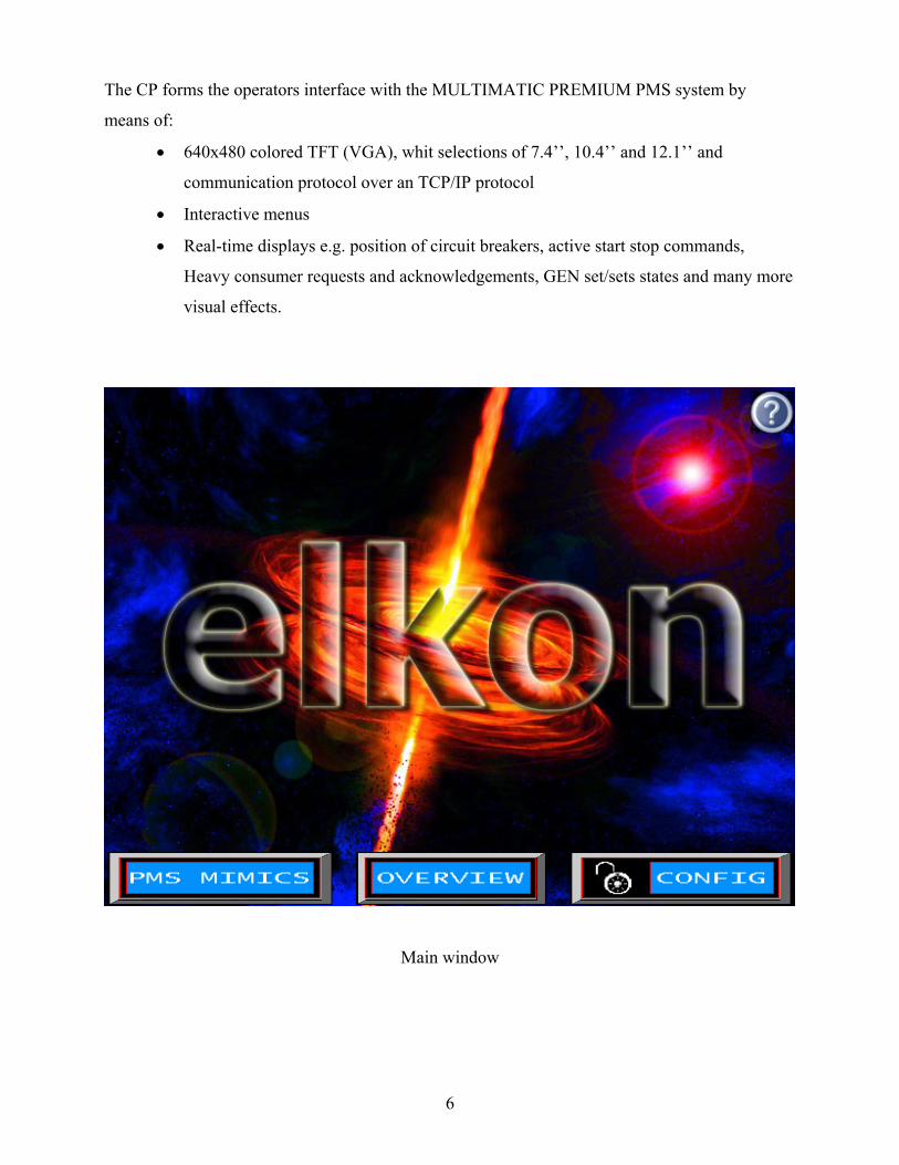
3.2 The Control Panel (touch screen)
3.2.1 MAIN window (default opening window)
Access to PMS mimics, System overview and Configuration pages
• Configuration page requires level-2 password (the lock mimic shows the condition of
the state of the access to the password protected pages).
• Project number
• Application version
• Information about the vessel
When touched on the question mark icon on the main page the information popup window appears.
11
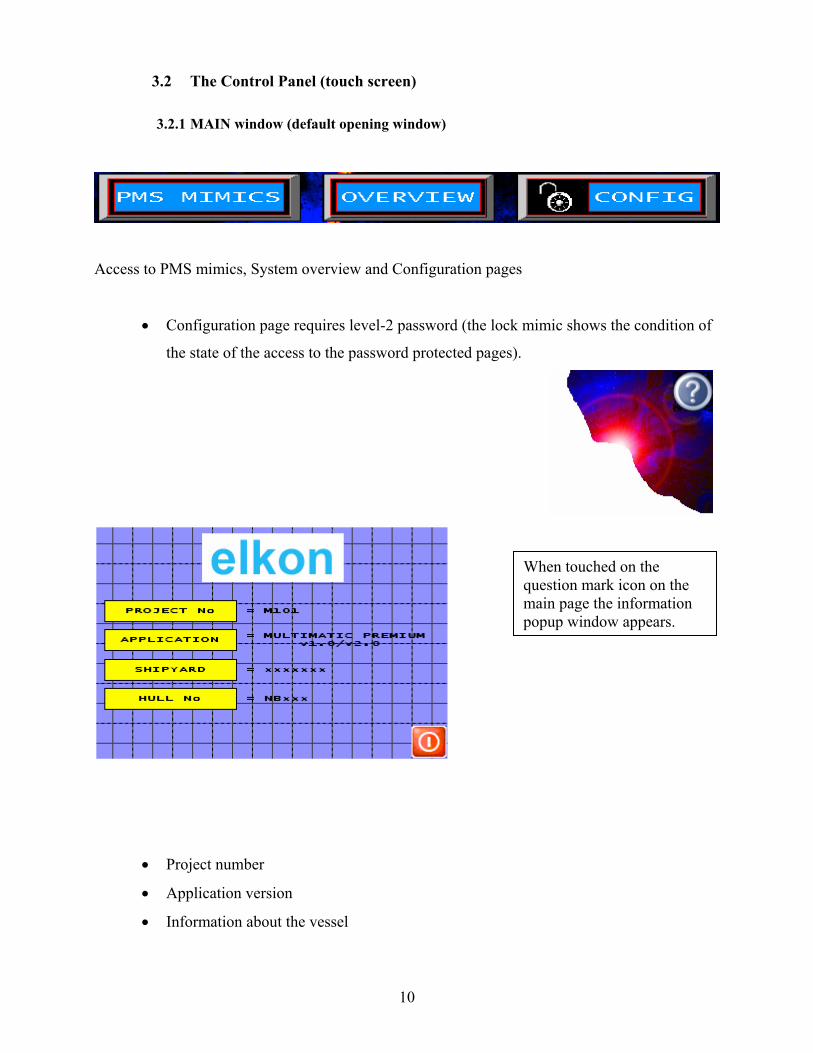
3.2.2 PMS mimic page
• Customized mimics of the Plant, Priority selection, Operators menu and the plant
mode selections
***Above picture is a demonstration of the transfer from SECURED mode to SG mode
12
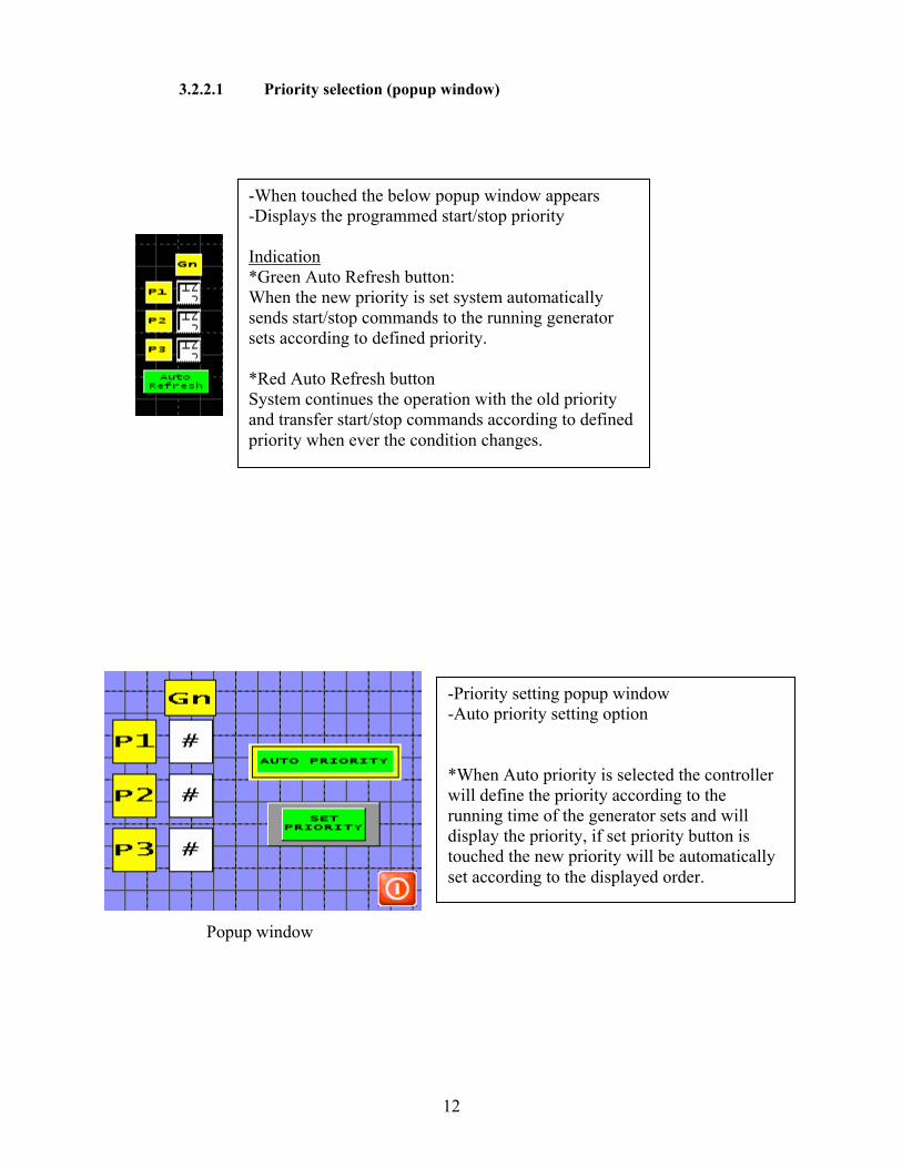
3.2.2.1 Priority selection (popup window)
Popup window
-When touched the below popup window appears -Displays the programmed start/stop priority Indication *Green Auto Refresh button: When the new priority is set system automatically sends start/stop commands to the running generator sets according to defined priority. *Red Auto Refresh button System continues the operation with the old priority and transfer start/stop commands according to defined priority when ever the condition changes.
-Priority setting popup window -Auto priority setting option *When Auto priority is selected the controller will define the priority according to the running time of the generator sets and will display the priority, if set priority button is touched the new priority will be automatically set according to the displayed order.
13
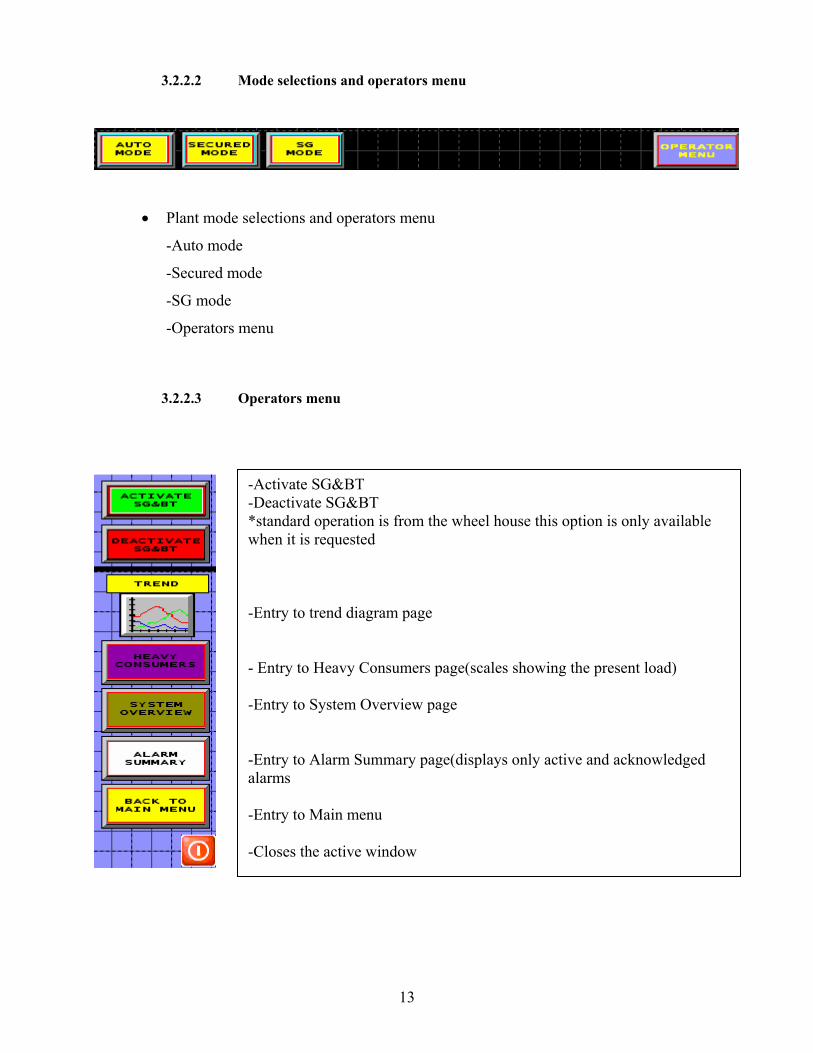
3.2.2.2 Mode selections and operators menu
• Plant mode selections and operators menu
-Auto mode
-Secured mode
-SG mode
-Operators menu
3.2.2.3 Operators menu
-Activate SG&BT -Deactivate SG&BT *standard operation is from the wheel house this option is only available when it is requested -Entry to trend diagram page - Entry to Heavy Consumers page(scales showing the present load) -Entry to System Overview page -Entry to Alarm Summary page(displays only active and acknowledged alarms -Entry to Main menu -Closes the active window

14
3.2.3 Alarm summary page
• Only the active and acknowledged alarms are displayed
• When the operator touches on the relevant alarm a pop up window will appear if the
alarm has a reset option
3.2.3.1 Alarm reset windows
When touched to the reset button all alarms related to the GEN set are resets only if the alarm condition is generated in the PMS system and can be reset. *Alarms that blocks the DG sets or the operations.
15
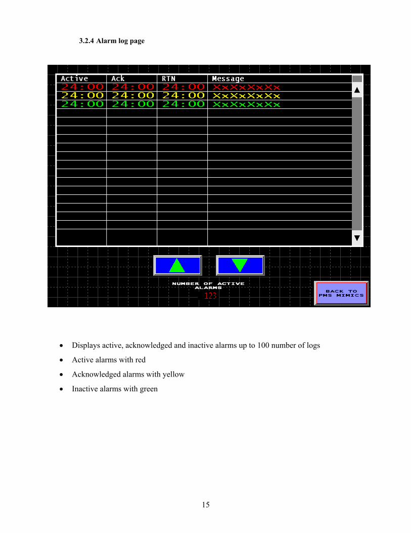
3.2.4 Alarm log page
• Displays active, acknowledged and inactive alarms up to 100 number of logs
• Active alarms with red
• Acknowledged alarms with yellow
• Inactive alarms with green

16
3.2.5 System configuration page
17
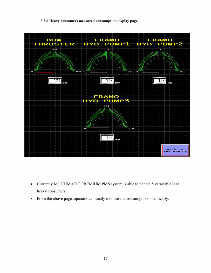
3.2.6 Heavy consumers measured consumption display page
• Currently MULTIMATIC PREMIUM PMS system is able to handle 5 varariable load
heavy consumers.
• From the above page, operator can easily monitor the consumptions identically.

18
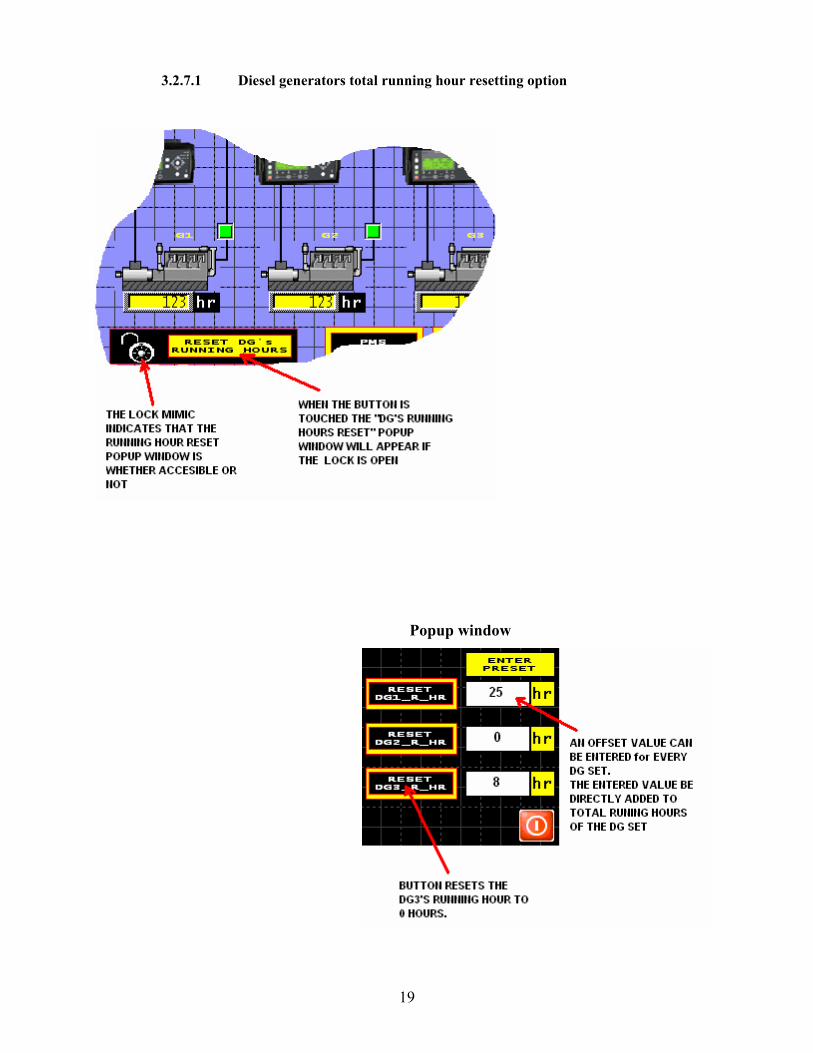
3.2.7 System overview page
• System overview page shows the lay out of your system.
• States of the PPU units and indications for the DG’s state(running/not running)
NOTE: The above system drawing mat not be the same as your system, this page is prepared
according to system installed on board.
19
3.2.7.1 Diesel generators total running hour resetting option
Popup window

20
3.2.8 Generator set block/the information popup window
• A DG is blocked if any of the above conditions are giving alarm(s) and will not be
considered in the load depending start stop function until the alarms related to the DG is
reset
21
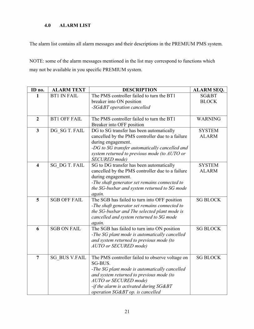
4.0 ALARM LIST
The alarm list contains all alarm messages and their descriptions in the PREMIUM PMS system.
NOTE: some of the alarm messages mentioned in the list may correspond to functions which
may not be available in you specific PREMIUM system.
ID no. ALARM TEXT DESCRIPTION ALARM SEQ. 1 BT1 IN FAIL The PMS controller failed to turn the BT1
breaker into ON position -SG&BT operation cancelled
SG&BT BLOCK
2 BT1 OFF FAIL The PMS controller failed to turn the BT1 Breaker into OFF position
WARNING
3 DG_SG T. FAIL DG to SG transfer has been automatically cancelled by the PMS controller due to a failure during engagement. -DG to SG transfer automatically cancelled and system returned to previous mode (to AUTO or SECURED mode)
SYSTEM ALARM
4 SG_DG T. FAIL SG to DG transfer has been automatically cancelled by the PMS controller due to a failure during engagement. -The shaft generator set remains connected to the SG-busbar and system returned to SG mode again.
SYSTEM ALARM
5 SGB OFF FAIL The SGB has failed to turn into OFF position -The shaft generator set remains connected to the SG-busbar and The selected plant mode is cancelled and system returned to SG mode again.
SG BLOCK
6 SGB ON FAIL The SGB has failed to turn into ON position -The SG plant mode is automatically cancelled and system returned to previous mode (to AUTO or SECURED mode)
SG BLOCK
7 SG_BUS V.FAIL The PMS controller failed to observe voltage on SG-BUS. -The SG plant mode is automatically cancelled and system returned to previous mode (to AUTO or SECURED mode) -if the alarm is activated during SG&BT operation SG&BT op. is cancelled
SG BLOCK

22
ID no. ALARM TEXT DESCRIPTION ALARM SEQ. 8 EXC.OFF FAIL The PMS controller failed to cancel excitation
of the SG, The PMS controller is still observing voltage on the SG-BUS
WARNING
9 SG CRIT.FAIL The PMS controller received a critical failure alarm from SG. -SG plant mode is automatically cancelled and AUTO mode is selected.
SG BLOCK
10 GB Short_Cir Detection of the DG breaker short circuit -A short circuit alarm blocks for blackout-start.
DG BLOCK
11 CB POS_FAIL A conflicting ON and OFF status has been detected at the position feedback signals from circuit breaker. -The DGU is forced into SWBD control and is as not included in the automatic PMS control
DG BLOCK
12 DG START FAIL The auxiliary engine is not running after execution of the programmed number of start attempts. -The defective generator set will not be ready for PMS start until the alarm has been reset. -The PMS start command has been transferred to next standby generator set.
DG BLOCK
13 GB ON FAIL The GB has failed to turn into ON position. -A PMS start command is transmitted to the next generator set which are to be started (according to the programmed start/stop priority)
DG BLOCK
14 GB OFF FAIL The GB has failed to turn into OFF position. -The generator set remain connected to the busbar and is included in the load share and load depending START/STOP function -A PMS stop command is transmitted to the next generator set which are to be stopped (according to the programmed start/stop priority)
DG BLOCK
15 DG CRIT.FAIL The PMS controller received a critical failure alarm from DG. PMS start command is transmitted to next standby DG.
WARNING
16 DG safety stop The PMS controller received a critical failure alarm from DG. -if the diesel generator is connected to the busbar, if not blocked in and PMS control safety stop sequence is activates -next standby generator set is started and connected to the busbar. When sufficient available power is measured at the busbar the defective generator set is disconnected and stopped (including cooldown etc.)
SAFETY STOP

23
ID no. ALARM TEXT DESCRIPTION ALARM SEQ. 17 SG PPU FAIL The PMS controller received a fault signal from
SG’s PPU. -PPU can either be reset from the control panel(CP) or directly from the PPU
SG BLOCK
18 DG PPU FAIL The PMS controller received a fault signal from DG’s PPU. -PPU can either be reset from the control panel(CP) or directly from the PPU
DG BLOCK
19 DG OVERLOAD Real power load on the generator set has exceeded the programmed limit for overload continuously during the programmed delay
WARNING
20 SG OVERLOAD Real power load on the generator set has exceeded the programmed limit for overload continuously during the programmed delay
WARNING
21 SG OVERLOAD-PTI
Nominal load in PTI mode exceeded the programmed limit for overload continuously during the programmed delay -reduce speed/pitch signal transmitted to propulsion control system.
WARNING
22 PWR AVAIL.LOW
The alarm message is generated by the load depending start/stop function as a result of one of the following situations: a)No further generator sets are ready for start and Predicted Available Power(PAP) has been continuously below the load start limit during the programmed delay b) No further generator sets are ready for start. A heavy consumer (HC) with variable load is currently connected to the busbar and is running with only a percentage of its nominal load. The spare load is still continuously reserved at the busbar. The ‘PWR AVAIL.LOW’ alarm is generated when increased load at busbar causes Available power to become less than the load start limit as described in case a).
WARNING
23 PTI.LOW.PWR The alarm message is generated when the Measured Available Power MAP is below the programmed PTI POWER AVAIL.LOW limit. --reduce speed/pitch signal transmitted to propulsion control system.
WARNING
24 BT1 POS.FAIL A conflicting ON and OFF status has been detected at the position feedback signals from BT1 circuit breaker.
BT OPER.BLOCK

24
ID no. ALARM TEXT DESCRIPTION ALARM SEQ. 25 TB POS OFF The tie breaker has been turned into OFF
position -All DG are left to SWBD control
WARNING
26 TB POS.FAIL A conflicting ON and OFF status has been detected at the position feedback signals from circuit breaker. -All DG are left to SWBD control
WARNING
27 BLACKOUT... Dead busbar detected -blackout sequence is started NOTE: A breaker short circuit alarm blocks for blackout start sequence
WARNING
28 PTI NOT READY
Failed to connect programmed number of generators in PTI mode. No available DG left to connect.
WARNING
29 BT2 POS.FAIL A conflicting ON and OFF status has been detected at the position feedback signals from BT2 circuit breaker.
BT OPER. BLOCK
30 REPLACE RAM BATTERY
PLC RAM Battery should be replaced WARNING

25
5.0 ALARM SEQUENCES
5.1 WARNING
The purpose of the warning sequence is to inform the operator of events.
5.2 DG BLOCK
The DG block alarm sequence is used for blocking of any further automatic functions which will
lead to connection of the generator set to busbar.
5.3 SAFETY STOP
The safety stop sequence is used to carry out a previous intervention and stop a defective engine,
Instead of waiting until a critical condition becomes fatal for the engine.
Safety stop sequence also can prevent a possible black-out situation at the busbar as it replace the
defective generator set before a shut down occurs on a running generator set.
Safety stop sequence starts and connects the next standby generator set to the busbar according to
chosen start/stop priority. When sufficient available power is measured at the busbar generator
set is disconnected and stopped (inc. cooldown etc.). As long as a critical failure signal is
received the defective DG will be blocked.
5.4 SG BLOCK
The SG block alarm sequence is used for blocking of any further automatic functions which will
lead to connection of the shaft generator set to busbar.
5.5 SG&BT BLOCK
The SG&BT BLOCK alarm blocks the SG&BT operation until the alarm is reset by the operator.
26
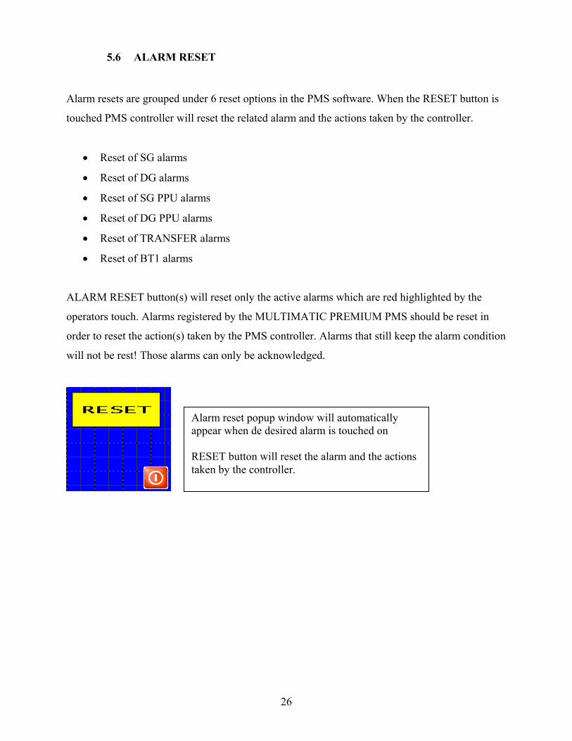
5.6 ALARM RESET
Alarm resets are grouped under 6 reset options in the PMS software. When the RESET button is
touched PMS controller will reset the related alarm and the actions taken by the controller.
• Reset of SG alarms
• Reset of DG alarms
• Reset of SG PPU alarms
• Reset of DG PPU alarms
• Reset of TRANSFER alarms
• Reset of BT1 alarms
ALARM RESET button(s) will reset only the active alarms which are red highlighted by the
operators touch. Alarms registered by the MULTIMATIC PREMIUM PMS should be reset in
order to reset the action(s) taken by the PMS controller. Alarms that still keep the alarm condition
will not be rest! Those alarms can only be acknowledged.
Alarm reset popup window will automatically appear when de desired alarm is touched on RESET button will reset the alarm and the actions taken by the controller.
27
6.0 THE SYSTEM SETUP (PARAMETER SETUP)
Each set-point and timer values are manually entered and stored in the PLC RAM memory with a
battery backup (PMS controller)
NOTE: each parameter should be entered during the commissioning; parameters that are not
entered and saved in to PLC memory will be 0 suppressed.
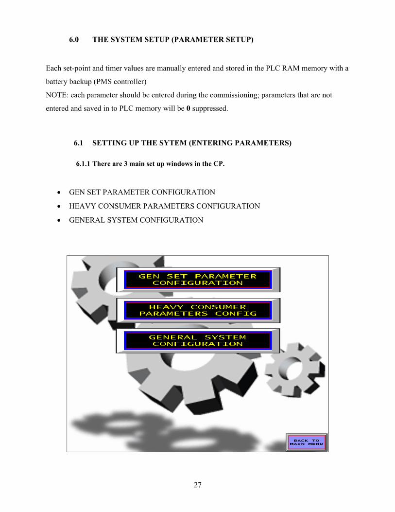
6.1 SETTING UP THE SYTEM (ENTERING PARAMETERS)
6.1.1 There are 3 main set up windows in the CP.
• GEN SET PARAMETER CONFIGURATION
• HEAVY CONSUMER PARAMETERS CONFIGURATION
• GENERAL SYSTEM CONFIGURATION

28
DIESEL GENERATOR SET PARAMETERS
DG1
MENU TEXT MIN MAX UNIT
1 DG1_NOM_POWER 0.0 10000.0 kW
2 START_ATTEMPTS 1.0 9.0 #
3 START_PREP 0.0 600.0 Sec
4 START_PULSE_H 1.0 30.0 Sec
5 START_PULSE_L 1.0 99.0 Sec
6 T_BEFORE_SYNC 0.0 10.0 Sec
7 GB1_ON_WAIT 10.0 120.0 Sec
8 GB1_OFF_WAIT 30.0 999.0 Sec
9 DG1_COOL_DOWN_T 0.0 999.0 Sec
10 DG1_MAX_STOP_T 10.0 120.0 Sec
11 EXTENDED_STOP 1.0 99.0 Sec
DG2
MENU TEXT MIN MAX UNIT
12 DG2_NOM_POWER 0.0 10000.0 kW
13 START_ATTEMPTS 1.0 9.0 #
14 START_PREP 0.0 600.0 Sec
15 START_PULSE_H 1.0 30.0 Sec
16 START_PULSE_L 1.0 99.0 Sec
17 T_BEFORE_SYNC 0.0 10.0 Sec
18 GB2_ON_WAIT 10.0 120.0 Sec
19 GB2_OFF_WAIT 30.0 999.0 Sec
20 DG2_COOL_DOWN_T 0.0 999.0 Sec
21 DG2_MAX_STOP_T 10.0 120.0 Sec
22 EXTENDED_STOP 1.0 99.0 Sec

29
DG3
MENU TEXT MIN MAX UNIT
23 DG3_NOM_POWER 0.0 10000.0 kW
24 START_ATTEMPTS 1.0 9.0 #
25 START_PREP 0.0 600.0 Sec
26 START_PULSE_H 1.0 30.0 Sec
27 START_PULSE_L 1.0 99.0 Sec
28 T_BEFORE_SYNC 0.0 10.0 Sec
29 GB3_ON_WAIT 10.0 120.0 Sec
30 GB3_OFF_WAIT 30.0 999.0 Sec
31 DG3_COOL_DOWN_T 0.0 999.0 Sec
32 DG3_MAX_STOP_T 10.0 120.0 Sec
33 EXTENDED_STOP 1.0 99.0 Sec
SHAFT GENERATOR PARAMETERS
MENU TEXT MIN MAX UNIT
34 SG_NOM_POWER 0.0 10000.0 kW
35 SG_NOM_PWR_PTI 1.0 9.0 kW
36 PRE_EXCITE 0.0 600.0 Sec
37 SG_BUS_VOLT_W 1.0 30.0 Sec
38 T_BEFORE_SYNC 1.0 99.0 Sec
39 SGB_ON WAIT 0.0 10.0 Sec
40 SGB_OFF_WAIT 10.0 120.0 Sec
30
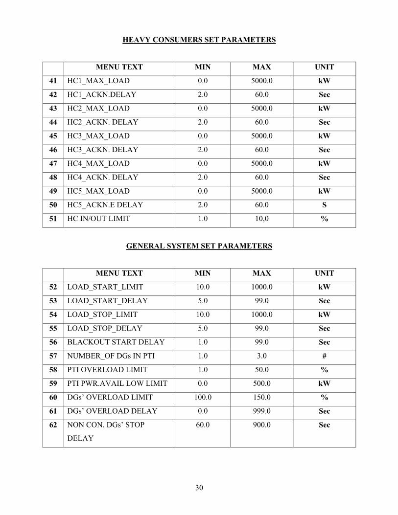
HEAVY CONSUMERS SET PARAMETERS
MENU TEXT MIN MAX UNIT
41 HC1_MAX_LOAD 0.0 5000.0 kW
42 HC1_ACKN.DELAY 2.0 60.0 Sec
43 HC2_MAX_LOAD 0.0 5000.0 kW
44 HC2_ACKN. DELAY 2.0 60.0 Sec
45 HC3_MAX_LOAD 0.0 5000.0 kW
46 HC3_ACKN. DELAY 2.0 60.0 Sec
47 HC4_MAX_LOAD 0.0 5000.0 kW
48 HC4_ACKN. DELAY 2.0 60.0 Sec
49 HC5_MAX_LOAD 0.0 5000.0 kW
50 HC5_ACKN.E DELAY 2.0 60.0 S
51 HC IN/OUT LIMIT 1.0 10,0 %
GENERAL SYSTEM SET PARAMETERS
MENU TEXT MIN MAX UNIT
52 LOAD_START_LIMIT 10.0 1000.0 kW
53 LOAD_START_DELAY 5.0 99.0 Sec
54 LOAD_STOP_LIMIT 10.0 1000.0 kW
55 LOAD_STOP_DELAY 5.0 99.0 Sec
56 BLACKOUT START DELAY 1.0 99.0 Sec
57 NUMBER_OF DGs IN PTI 1.0 3.0 #
58 PTI OVERLOAD LIMIT 1.0 50.0 %
59 PTI PWR.AVAIL LOW LIMIT 0.0 500.0 kW
60 DGs’ OVERLOAD LIMIT 100.0 150.0 %
61 DGs’ OVERLOAD DELAY 0.0 999.0 Sec
62 NON CON. DGs’ STOP
DELAY
60.0 900.0 Sec

31
7.0 HOW TO SET A SET POINT OR TIMER
It is extremely easy to set the parameters from the CP. The entered values will directly be written
to PLC memory without any other operation.
-just touch on the desired parameters entry field and a popup keypad is opened
-enter the set point or timer value by using the keypad
NOTE: every entry field has minimum and maximum limits for the value to be entered for the
related parameter; if the value entered is not between the programmed range value will not be
written to memory!
After entering the set-point or timer value it should be set by pressing the ENT (enter) button!

32
8.0 PLANT MODES
The MULTIMATIC PREMIUM PMS Multi function system operates according to the
functionalism of the selected plant mode.
The plant modes are automatic functions according to the functionalism of the selected mode.
This means every function may not be carried out in every mode.
The system is able to handle the fallowing plant modes:
• AUTOMATIC MODE
• SECURED MODE
• SHAFT GENERATOR MODE
The selection of the plant mode for the entire power plant is done by the buttons located on the
PMS mimic page of the CP.
Red button indicates that the mode is not available. Yellow button indicates that the mode is ready. Green button indicates that the mode is running. Blue flashing button indicates that the mode is selected but in still progress.

33
8.1 Automatic functions in the M-PREMIUM system
X = active - = inactive
AUTOMATIC PMS FUNCTIONS
SWBD
VONTROL
AUTO
MODE
SECURED
MODE
1 Load depending start/stop - x x
2 Selection of start/stop priority x x x
3 Automatic refresh according to priority - x -
4 Symmetrical load share - x x
5 Black-out start - x x
6 Shore connection supervision x x x
7 Conditional connection of heavy
consumers
- x x
8 Tie breaker supervision x x x
9 Selection of SG mode - x x
10 PTI mode - x x
11 Selection of SG&BT operation - x x
GENERATOR SET FUNCTIONS
SWBD
VONTROL
AUTO
MODE
SECURED
MODE
12 Automatic star sequence - x x
13 GB ON sequence - x x
14 GB OFF sequence - x x
15 Automatic stop sequence - x x
16 Non connected generator stop sequence - x x
17 Safety stop sequence - x x
*** Some of the above functions are optional and may not be available in your system.

34
9.0 OPERATING PRINCIPLES OF PLANT MODES
9.1 AUTO plant mode
During this full-automatic mode, called AUTO mode, the PMS control is carried out by all
generator sets which are under PMS and REMOTE control.
Load depending start and stop function of the generator sets are carried out according to the
actual power demand at the busbar with respect to; the programmed start/stop priority and the
programmed limits for start and stop.
The load depending start/stop function take any running generator set which fail during
engagement in consideration, by starting up the next standby generator set and substitute the
defective one.
If the system detects a black-out situation, a conditional black-out start of two generator sets is
carried out.
9.2 SECURED plant mode
The SECURED plant mode is almost the same as the AUTO MODE.
When the SECURED mode is selected automatically the largest connected generator sets
nominal load is taken in to consideration and the Load depending start stop limit is increase by
the nominal load of the largest connected generator set.
This means that the nominal load of the largest connected set is available at the busbar at any
time during SECURED mode.
The SECURED plant mode prevents a blackout situation ay be caused by a sudden cut out of a
generator set from the busbar.
35
9.3 SHAFT GENERATOR mode (SG mode)
Selection of SG plant mode is only accepted by the PMS controller if:
• All running generator sets are ready for PMS stop
• The shaft generator is able to substitute the total power produced by the running diesel
generators
• If the system is receiving constant speed signal
And the plant mode is either SECURED or AUTO mode.
At once the SG mode is selected system automatically sends excitation signals to shaft alternator
and end examines the generators voltage when the shaft generators voltage is ok, the
synchronization of the diesel generator set(s) to shaft generator takes place.
The SG plant mode is automatically cancelled if:
• A failure occurs during the engagement of shaft generator.
During an active SG plant mode conditional connection of heavy consumers are allowed as long
as the shaft generator is able to handle the predicted power demand at the busbar.
An ongoing SG plant mode is automatically cancelled if:
• Black-out is detected
• When the operator selects AUTO or SECURED mode
• When the SG&BT operation is selected
*** During the SG mode the nominal load of the shaft generator is continuously examined and
when the shaft generator power exceeds the total nominal power of the PMS ready generator sets
Selection of AUTO, SECURED and SG&BT modes are blocked.

36
10.0 LOAD DEPENDENT START/STOP FUNCTION
The load dependent start/stop function is active when AUTO or SECURED mode is selected and
the shore connection breaker is not closed and the tie breaker is closed.
The start/stop function transmits PMS start and stop commands, which are based on a calculation
of how many generator sets are needed in order to satisfy the actual power demand at the busbar.
The PMS start/stop commands are sent to individual generator set according to the selected
start/stop priority.
Transmission of the Load depending PMS start/stop commands are based on the comparison of
the programmed start/stop limits and a special M-PREMIUM value PAP (predicted available
power).
37
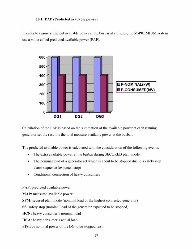
10.1 PAP (Predicted available power)
In order to ensure sufficient available power at the busbar at all times, the M-PREMIUM system
use a value called predicted available power (PAP).
0
100
200
300
400
500
600
DG1 DG2 DG3
P-NOMINAL(kW)P-CONSUMED(kW)
Calculation of the PAP is based on the summation of the available power at each running
generator set the result is the total measure available power at the busbar.
The predicted available power is calculated with the consideration of the following events.
• The extra available power at the busbar during SECURED plant mode.
• The nominal load of a generator set which is about to be stopped due to a safety stop
alarm sequence (expected stop)
• Conditional connection of heavy consumers
PAP: predicted available power
MAP: measured available power
SPM: secured plant mode (nominal load of the highest connected generator)
SS: safety stop (nominal load of the generator expected to be stopped)
HCN: heavy consumer’s nominal load
HCA: heavy consumer’s actual load
PFstop: nominal power of the DG to be stopped first

38
PAP=MAP – SPM – SS - (HCN - HCA)
PAP= 600 kW – 0 kW – 0 kW – (300 kW– 0kW)
PAP= 300 kW
*** Example represents calculation of the PAP in case of heavy consumer start
10.1.1 Programming of the load dependent start limit
Generation of the load dependent PMS start command is based on a comparison of the PAP at the
busbar and the programmed start limit (LOAD START LIMIT) in the system.
Start command is transmitted to next standby generator time delayed if PAP < LOAD START
LIMIT in order avoid unnecessary start of a generator set.
*** Delay is time equals to the programmed timer value as LOAD DEPENDENT STAR
DELAY.
10.1.2 Programming the load dependent stop limit
The PMS stop command is generated by comparing the programmed stop limit value with the
result of the following calculation; PAP is deduced with the nominal load of the generator set
designated with the highest stop priority.
PFstop: nominal power of the DG to be stopped first
PAPs = PAP – PFstop PAPs = 300 kW– 600 kW
PAPs = -300 Kw
Programmable stop limit represents the desired remaining available power at the busbar after load
depending PMS stop of the generator is carried out.

39
Therefore system uses PAPs calculated value with the LOAD DEPENDENT STOP LIMT and
decides whether to send a PMS stop command or not.
Stop command is transmitted to next standby generator time delayed if PAPs > LOAD STOP
LIMIT in order avoid unnecessary start of a generator set.
*** Delay is time equals to the programmed timer value as LOAD DEPENDENT STOP
DELAY.

40
10.2 SELECTION OF START/STOP PRIORITY
The load depending start/stop function uses the programmed priority information when the start
stop commands are to be transmitted.
NOTE: the start/stop priority keeps account with which diesel generators are ready for PMS start
and which are ready for PMS stop. Any generator set which, during operation becomes not ready
are not accepted as the next generator to be started or stopped.
10.2.1 Setting of the start/stop priority
Manual designation of the desired priority:
*** Programming and read out of the start/stop priority is from the CP.
The M-PREMIUM system will not except two or more generator sets to be programmed with the
same start/stop priority or other than 1,2 and 3. Refer to the figure below. Wrong selection
indication will appear when the system refuses the setting.
Wrong selection indication blocks for priority setting.

41
Automatic designation of the desired priority:
This function ensures the operating hours are equally distributed at all generator sets in the power
plan
M-PREMIUM system counts and logs the operating hours of the generator sets and when desired
the start/stop priority is designed according to the operating hours of the generators.
This is done by the following steps:
1. press the AUTO PRIORITY button
2. Press SET PRIORITY button
e.g. The start priority before the automatic designation is
P1=1 dg1 TOTAL RUN HOURS=12340 ***
P2=2 dg2 TOTAL RUN HOURS=12320 *
P3=3 dg3 TOTAL RUN HOURS=12330 **
The start priority after the automatic designation is
P1=2 dg1 TOTAL RUN HOURS=12320 ***
P2=3 dg3 TOTAL RUN HOURS=12330 **
P3=1 dg1 TOTAL RUN HOURS=12340 *
-After pressing the AUTO PRIO button the indication ‘AUTO PRIORTY IS SELECTED SET IN 15 s’ appears -Operator has 15b seconds to set the designed priority -If it is not set in 15 seconds priority will be left with the previous setting

42
10.3 DETERMINATION OF START PRIORITY
The PMS controller designates each generator set with a PMS start priority number according to
the programmed Priority sequence.
P1= 2 dg2 to be started first
P2= 1 dg1 to be started second
P3= 3 dg3 to be started last
10.4 DETERMINATION OF STOP PRIORITY
The PMS controller designates each generator set with a PMS stop priority number according to
the programmed Priority sequence.
P1= 2 dg2 to be stopped last
P2= 1 dg1 to be stopped second
P3= 3 dg3 to be stopped first

43
11.0 BLACK-OUT FUNCTION
The black-out function is active when ever the following plant modes are selected
• AUTO mode
• SECURED mode
• SG mode
Detection of dead busbar status activates the black-out start sequence.
*** A short circuit alarm at any DG will block the entire black-out function
DG2DG1 DG3
BLACK-OUT FUNCTION
PROGRAMMABLE START/STOP
PRIORITY
DG no: Y DG no: X
BALCK-OUT START
PMS ready PMS ready PMS ready
44
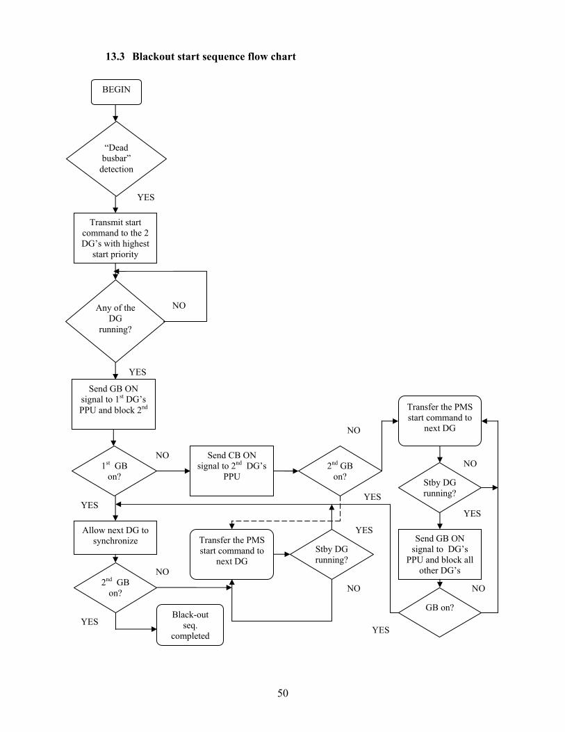
11.1 The black-out start sequence
Activation of black out sequence is only available if;
• There is no short circuit alarm from and circuit breaker
• All circuit breakers are in OFF position
• At least one of the DG are in PMS control
NOTE: A synchronization alarm is automatically acknowledged (reset) in case of an active dead
busbar status. But not the start failure alarms.
The black-out start sequence carries out the following step by step
a) A PMS start command is transmitted to DG’s with the highest and second start priorities,
which at the same time ready for PMS start.
b) A CB ON/SYNCRONIZE command is immediately transferred to the PPU of the first
running DG
*** if this does result in the closing of the generator breaker the other Black-out started
generator will be requested to close its breaker after 2 seconds delay.
c) A CB ON/SYNCRONIZE command is transmitted to the second black out started
generator’s PPU will be requested to close its breaker after 2 seconds delay.
d) If any of the two chosen generator sets fails during the start sequence the PMS start
command is transferred to the next standby generator as long as the black-out situation is
present.
e) When one generator sets is successfully connected to busbar approx. after 2 seconds the
black out situation is considered to be completed.

45
12.0 CONDITIONAL CONNECTION OF HEAVY CONSUMERS
M-PREMIUM PMS system is able to handle 5 conditional connection of heavy consumers
(HC’s)
When requested by a heavy consumer, function for conditional connection of heavy consumers
reserves the programmed max. Power at the busbar and block for engagement of the heavy
consumer until sufficient predicted power is present at the busbar.
If PAP > LOAD START LIMIT (HC) is acknowledged.
Acknowledge signal is set with delay in order to let the recently started generator set(s) to take
load and thus actually increasing the available power at the busbar before engagement of the HC.
The heavy consumers are acknowledged according to their priority.
If two or more heavy consumers requests for start acknowledgement at the same time the HC
with the highest priority is handled first, subsequently with lower and etc.
HC1 is designated the highest priority in the M-PREMIUM system, HC 1 is handled before HC 2
HC 3 and HC 4 and so on.
NOTE: If there are any preferential Heavy consumers they should be connected to M-PREMIUM
system in the order 1,2,3,4 and 5 in order to ensure right the priority.
The M-PREMIUM system carryout the following step by step sequence, when a HC request for
start acknowledgement:
a) The programmed “HC n MAX POWER” value is reserved at the busbar.
b) A PMS start command is transmitted to the next stand by generator set if PAP is below
the programmed “LOAD START LIMIT”.
c) When sufficient predicted available power is present at the busbar. The timer
“HCn_ACKN.DELAY” starts running.

46
d) When the timer “HCn_ACKN.DELAY” runs out acknowledge signal is transmitted to the
HC in request.
The M-PREMIUM system uses analog power feed back.
• 0..10 VDC
• 0..20 mA
• 4..20 mA

47
12.1 Start of heavy consumer with analog power feedback
Start of a specific heavy consumer with variable load (HCn) is made by activating the
corresponding start request input.
*** The start request signal must remain activated for as long as the HC are to be operation.
Power reservation ends when the start request signal disappears.
The acknowledge signals duration is 3 s.
In order to prevent overload at busbar during the operation of HC, the actual power consumed by
the HC (measured by analog feedback) is taken in to consideration. The reserved power at the
busbar for this HC is reduced (from maximum power) with actually consumed power. This
calculation is continuously made in order to optimize the reserved power at busbar.
Start req. HC
Start ack. HC
Delay ack. HC
p-avail OK p-avail OK
100% 100%
100%
70% 50% 30%
30% 50% 70%
PWR reserve at the busbar
HC consumed PWR feedback

48
13.0 LOGIC FLOW CHARTS
13.1 Load depending PMS start command flow chart
BEGIN
Available pwr too
low?
Any DG’s for PMS
start?
Load depending start timer starts
running
Timer run out?
Send PMS start command to stand-by DG
DG running?
Available pwr too
low?
No load depending PMS
start
NO
YES
YES
YES
YES
NO
NO
P-AVAIL LOW timer
starts running
Any DG’s for PMS
start?
Timer run out?
Available pwr too
low?
NO
YES
NONO
YES
PWR AVAIL.LOW
alarm
YES
NO

49
13.2 Load depending PMS stop command flow chart
BEGIN
Load depending stop timer starts
running
Timer run out?
Send PMS stop command to stand-by DG
DG stopped?
YES
YES
YES
YES
Available pwr high enough?
Any DG’s for PMS
stop?
Available pwr high enough?
No load depending PMS
stop
NO
NO
NO
YES
NO
50
13.3 Blackout start sequence flow chart
BEGIN
“Dead busbar”
detection
Transmit start command to the 2 DG’s with highest
start priority
Any of the DG
running?
YES
NO
YES
Send GB ON signal to 1st DG’s PPU and block 2nd
1st GB on?
Allow next DG to synchronize
2nd GB on?
Black-out seq.
completed YESYES
Transfer the PMS start command to
next DG Stby DG running?
NO
NO
YES
Send CB ON signal to 2nd DG’s
PPU
NO 2nd GB
on?
YES
Transfer the PMS start command to
next DG
Stby DG running?
Send GB ON signal to DG’s
PPU and block all other DG’s
NO
GB on?
YES YES
NO
NO
51
13.4 Automatic GB ON start sequence flow chart
BEGIN
GB ON/synchronize command delay
timer starts running
YES
YES
Send GB ON signal to DG’s
PPU
NO
DG is running?
Timer run out?
GB ON/synchronize
timer starts running
NOTimer
run out?
YES
YES GB ON sequence completed
YES
GB ON?
GB ON?
NO GB ON failure
alarm
NO Transfer the PMS start command to
next DG
52
13.5 Automatic start sequence flow chart
Set start prepare output and start
timer
YES
YES
Set start output and start ON-
timer
NO
Ready for start
Timer run out?
YES
NO
BEGIN
Running status ok?
NO On-timer run out?
NO
Clear start out wait sync.wait
delay
Running status ok?
Start sequence completed
YES
NO Start failure
alarm
Transfer the PMS start command to
next DG
Transfer the PMS start command to
next DG
Clear start output wait OFF time Increment start
attempts
Max start attempts?
NO YES Start failure
alarm
Non-connected DG stop sequence
starts
YES
53
13.6 Automatic GB OFF start sequence flow chart
BEGIN
GB OFF wait timer starts
running
YES
Ready for GB OFF ?
NO
Send GB OFF/deload signal
to DG’s PPU
NOTimer
run out?
YES GB OFF sequence completed
YES
GB OFF?
GB OFF?
NO GB OFF failure
alarm
NO Transfer the PMS stop command to
next DG
54
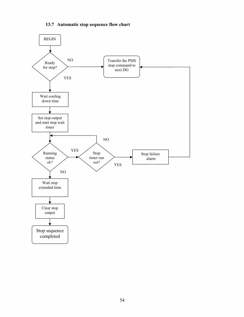
13.7 Automatic stop sequence flow chart
Wait cooling down time
YES
YES
Set stop output and start stop wait
timer
Ready for stop?
NO
Running status ok?
NO
Stop timer run
out?
NO
Wait stop extended time
Stop sequence completed
Clear stop output
Transfer the PMS stop command to
next DG
YES
BEGIN
Stop failure alarm
55
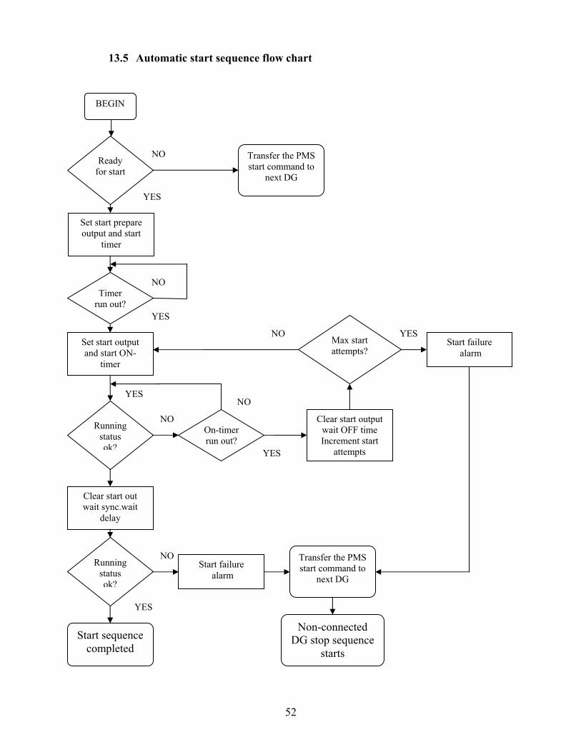
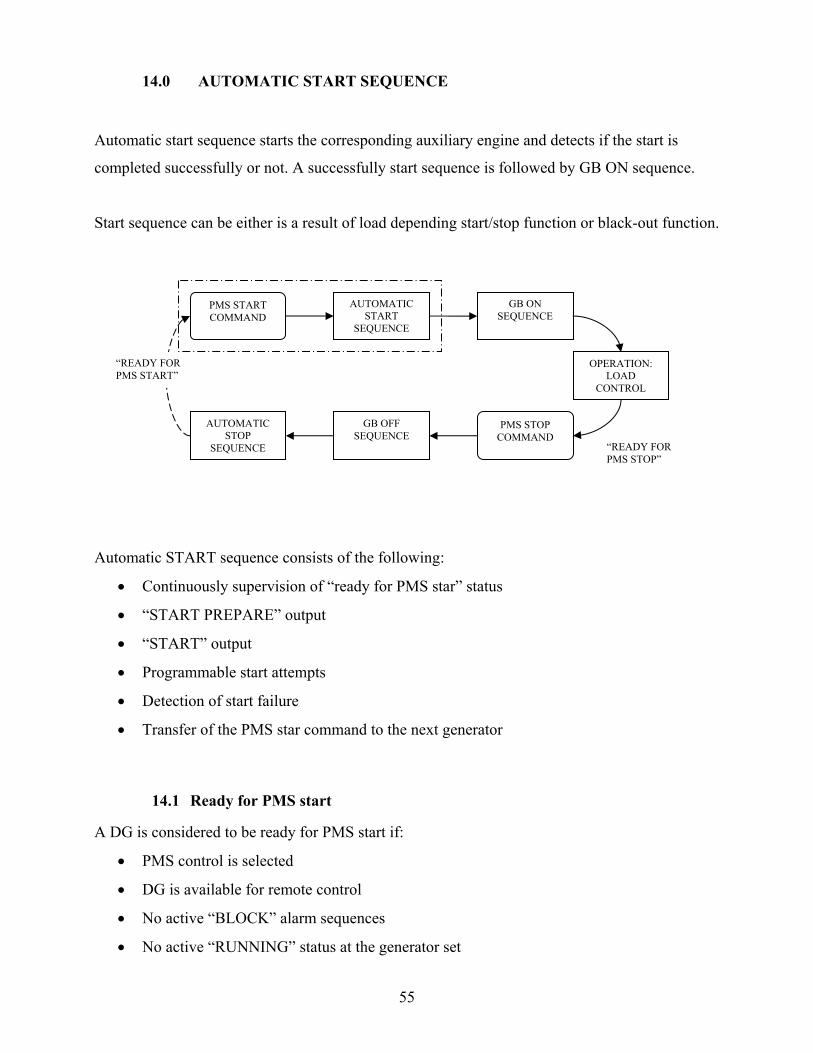
14.0 AUTOMATIC START SEQUENCE
Automatic start sequence starts the corresponding auxiliary engine and detects if the start is
completed successfully or not. A successfully start sequence is followed by GB ON sequence.
Start sequence can be either is a result of load depending start/stop function or black-out function.
Automatic START sequence consists of the following:
• Continuously supervision of “ready for PMS star” status
• “START PREPARE” output
• “START” output
• Programmable start attempts
• Detection of start failure
• Transfer of the PMS star command to the next generator
14.1 Ready for PMS start
A DG is considered to be ready for PMS start if:
• PMS control is selected
• DG is available for remote control
• No active “BLOCK” alarm sequences
• No active “RUNNING” status at the generator set
PMS START COMMAND
AUTOMATIC START
SEQUENCE
GB ON SEQUENCE
OPERATION: LOAD
CONTROL
PMS STOP COMMAND
GB OFF SEQUENCE
AUTOMATIC STOP
SEQUENCE
“READY FOR PMS START”
“READY FOR PMS STOP”
56
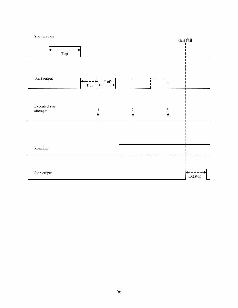
Start prepare
Start output
Executed start attempts
Running
T sp
T on T off
1 2 3
Start fail
Stop output Ext.stop
57
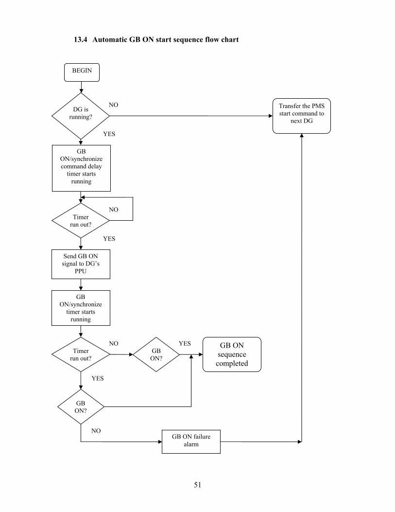
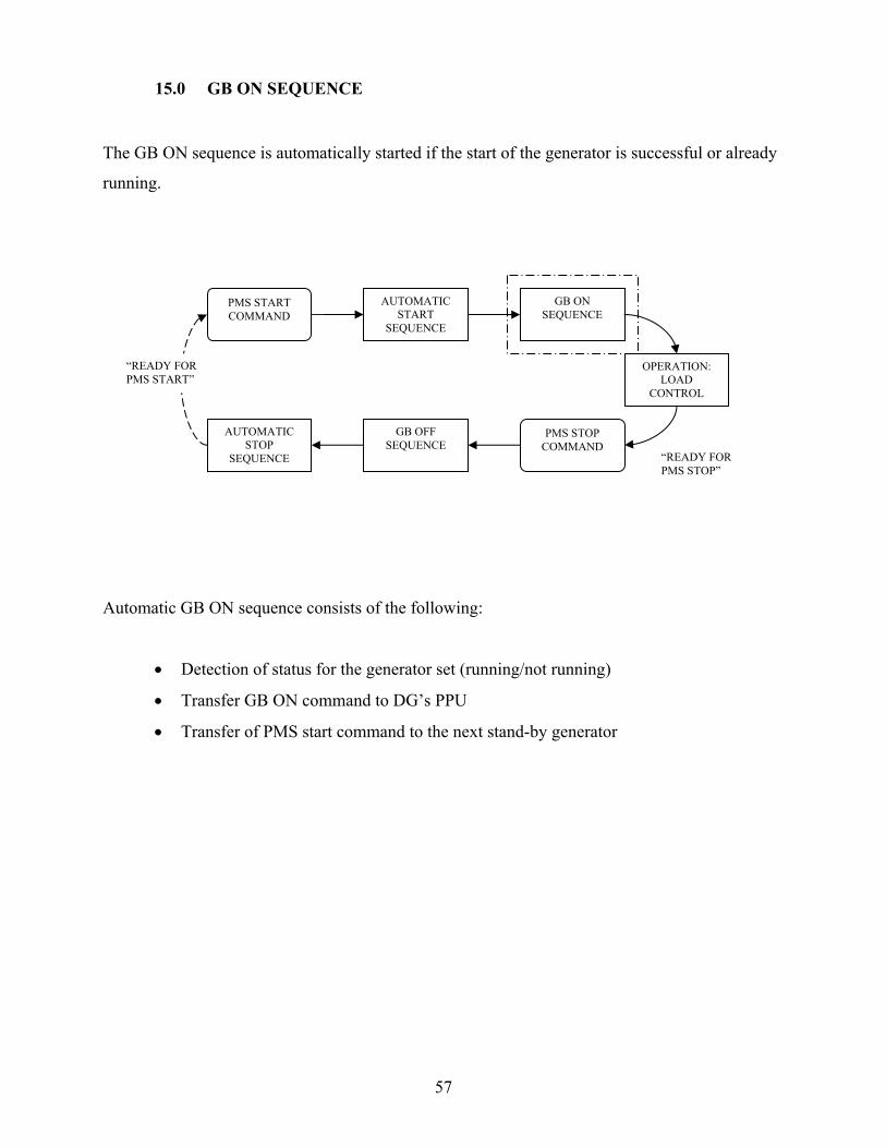
15.0 GB ON SEQUENCE
The GB ON sequence is automatically started if the start of the generator is successful or already
running.
Automatic GB ON sequence consists of the following:
• Detection of status for the generator set (running/not running)
• Transfer GB ON command to DG’s PPU
• Transfer of PMS start command to the next stand-by generator
PMS START COMMAND
AUTOMATIC START
SEQUENCE
GB ON SEQUENCE
OPERATION: LOAD
CONTROL
PMS STOP COMMAND
GB OFF SEQUENCE
AUTOMATIC STOP
SEQUENCE
“READY FOR PMS START”
“READY FOR PMS STOP”
58
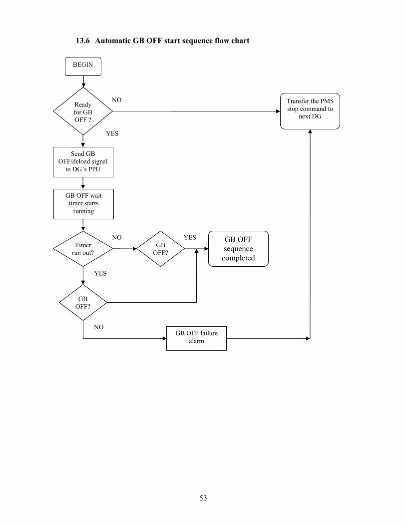
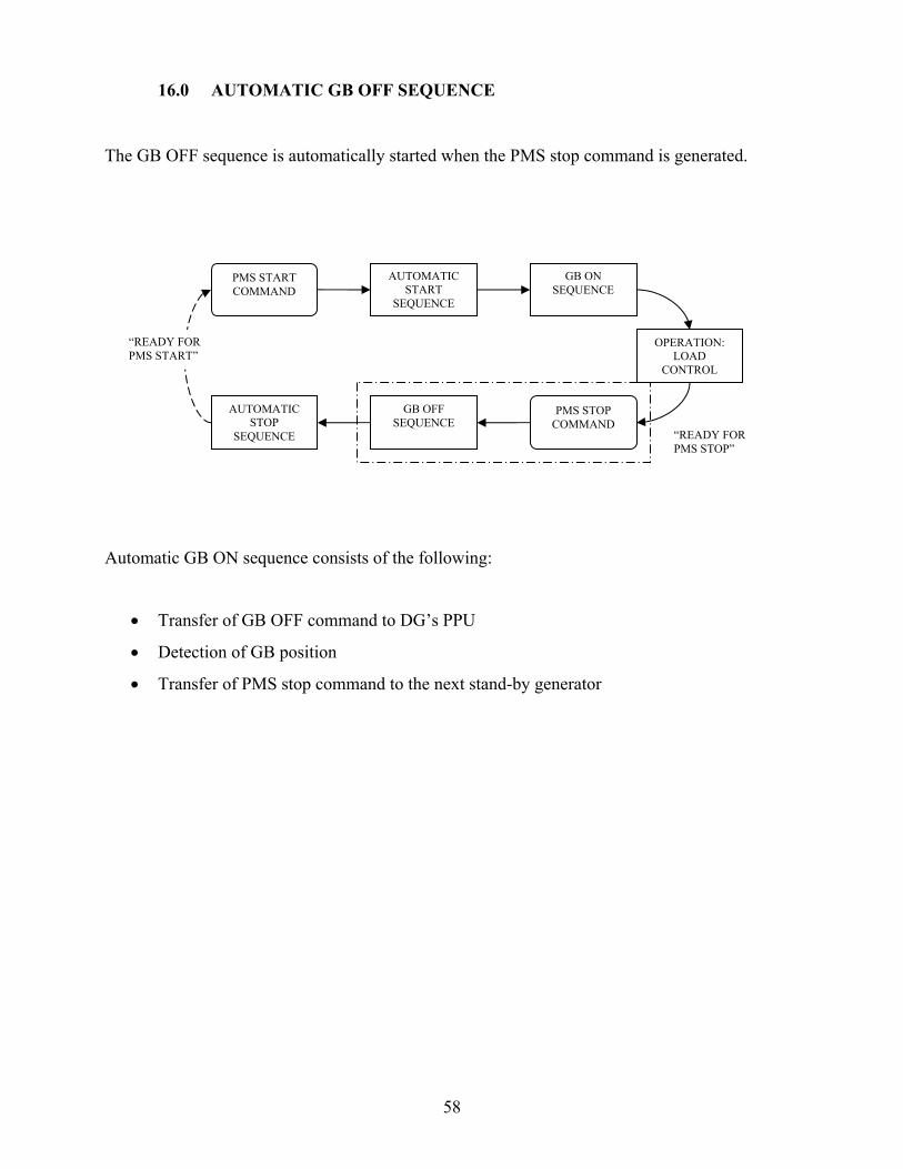
16.0 AUTOMATIC GB OFF SEQUENCE
The GB OFF sequence is automatically started when the PMS stop command is generated.
Automatic GB ON sequence consists of the following:
• Transfer of GB OFF command to DG’s PPU
• Detection of GB position
• Transfer of PMS stop command to the next stand-by generator
PMS START COMMAND
AUTOMATIC START
SEQUENCE
GB ON SEQUENCE
OPERATION: LOAD
CONTROL
PMS STOP COMMAND
GB OFF SEQUENCE
AUTOMATIC STOP
SEQUENCE
“READY FOR PMS START”
“READY FOR PMS STOP”

59
17.0 AUTOMATIC STOP SEQUENCE
Automatic stop sequence is started if the GB OFF sequence is successfully completed.
Automatic STOP sequence consists of the following:
• Programmable cooling down time
• STOP output with extended wait time
• Detection of the generators status (running/not running)
PMS START COMMAND
AUTOMATIC START
SEQUENCE
GB ON SEQUENCE
OPERATION: LOAD
CONTROL
PMS STOP COMMAND
GB OFF SEQUENCE
AUTOMATIC STOP
SEQUENCE
“READY FOR PMS START”
“READY FOR PMS STOP”

60
1 maximum stop timer starts running
2 DG STOP alarm is generated if the running feedback still is present when timer runs
out.
Note: The cooling down sequence may be interrupted if a new PMS start command is
generated
Cool down of Aux. engine
Stop output
Running feedback
Cooling down time
T ext
Stop fail
1 2 Maximum stop time

61
18.0 SHAFT GENERATOR CONTROL AND SUPERVISION
The shaft generator control consists of a number of automatic sequences. These automatic
functions altogether form a complete cycle of operation for the shaft generator.
The shat generator is activated by means of the SG plant mode
Selection and cancellation of the SG plant mode is able to respectively initiate and complete the
cycle of operation for the SG.
Selected SG plant mode is automatically cancelled and auto mode is selected if a failure occurs
during the engagement of the SG, or a blackout occurs at the busbar.
e.g. SG voltage is not in expectable limits, PPU is unable to complete SGB on sequence.
SELECTION OF SG PLANT
MODE
SHAFT GENERATOR
VOLTAGE OK?
SGB ON SEQUENCE LOAD TRANSFER
OPERATION: LOAD
CONTROL
SELECTION OF AUTO/SECURED
MODE
PMS START OF GENERATOR SET(S): SYNCRONIZATION
“READY FOR SG MODE”
SGB OFF SEQUENCE: LOAD
TANSFER
FAILURE!
FAILURE!
Obligatory selection of auto mode conditions
AUTOMATIC SELECTION OF
PREVIOUS PLANT MODE
AUTOMATIC SELECTION OF AUTO PLANT
MODE

62
Obligatory selection of Auto plant mode:
• Immediately after losing constant speed feedback
• Immediately after losing SG bus voltage
• Immediately after receiving slowdown signal
The M-PREMIUM is able to carry out the following automatic sequences during the shaft
generator operation:
• Selection of SG plant mode
• SGB ON sequence:
-load transfer from diesel generators to shaft generator
• Load supervision during operation
• Selection of Auto plant mode
-Automatic start of the stand-by generators
• SGB OFF sequence
-De-loading of the shaft generator / load transfer from the shaft generator to diesel
generators.

63
18.1 SGB ON SEQUENCE
The SGB ON sequence is automatically initiated once the SG plant mode is selected.
SGB ON sequence is automatically cancelled previous mode is automatically selected if SG
voltage is not in acceptable limits and if SG PPU is failed to close the SGB.
SG plant mode selection button will start to flash during the transfer until the transfer is
completed successfully or a failure occurs during the engagement.
SELECTION OF SG PLANT
MODE
SHAFT GENERATOR
VOLTAGE OK?
SGB ON SEQUENCE LOAD TRANSFER
OPERATION: LOAD
CONTROL
SELECTION OF AUTO/SECURED
MODE
PMS START OF GENERATOR SET(S): SYNCRONIZATION
“READY FOR SG MODE”
SGB OFF SEQUENCE: LOAD
TANSFER
FAILURE!
FAILURE!
Obligatory selection of auto mode conditions
AUTOMATIC SELECTION OF
PREVIOUS PLANT MODE
AUTOMATIC SELECTION OF AUTO PLANT
MODE

64
18.1.1 Load transfer from DG’s to SG
Once the shaft generators breaker is successfully synchronized and cut-in at the busbar, the load
transfer from the running diesel generator sets to shaft generator is initiated.
This is done by sending GB OFF/DELOAD commands to all running generator set’s PPU’s.
*** Diesel generator set de-loading is carried out by the PPU of the DG set.
NOTE: if a failure such as “DGB OFF FAIL” occurs during the load transfer of any running
generator sets, the SG plant mode is cancelled and the AUTO plant mode is automatically
selected again.
18.2 LOAD SUPERVISION DURING SG PLANT MODE
The load depending start stop function is disabled when the SG plant mode is selected.
Calculation of the PAP is continuously carried out as a hidden function. And during an ongoing
SG plant mode supervision of predicted available power PAP is also active.
The conditional connection of heavy consumers is also available in SG plant mode like in Auto
or Secured plant modes.
If the calculated PAP becomes below 0 kW when any of the heavy consumers requests for start
the start is denied acknowledge signal is not transmitted.

65
18.3 SGB OFF SEQUENCE
The automatic SGB OFF sequence is initiated, if one of the blow mentioned events occurs:
• The operator selects AUTO or SECURED plant mode
• The SG&BT operation is selected by the operator
Or
• The SG plant mode is cancelled automatically by the M-premium system when the
constant speed signal is lost, slowdown signal is received or the SG bus voltage is below
the acceptable limits.
If any of the above mentioned event occurs M-premium automatically calculates the power
needed to substitute the actual real power produced by the shaft generator and sends PMS start
commands to the DG’s which has the total nominal power in order to substitute the SG.
SELECTION OF SG PLANT
MODE
SHAFT GENERATOR
VOLTAGE OK?
SGB ON SEQUENCE LOAD TRANSFER
OPERATION: LOAD
CONTROL
SELECTION OF AUTO/SECURED
MODE
PMS START OF GENERATOR SET(S): SYNCRONIZATION
“READY FOR SG MODE”
SGB OFF SEQUENCE: LOAD
TANSFER
FAILURE!
FAILURE!
Obligatory selection of auto mode conditions
AUTOMATIC SELECTION OF
PREVIOUS PLANT MODE
AUTOMATIC SELECTION OF AUTO PLANT
MODE
66
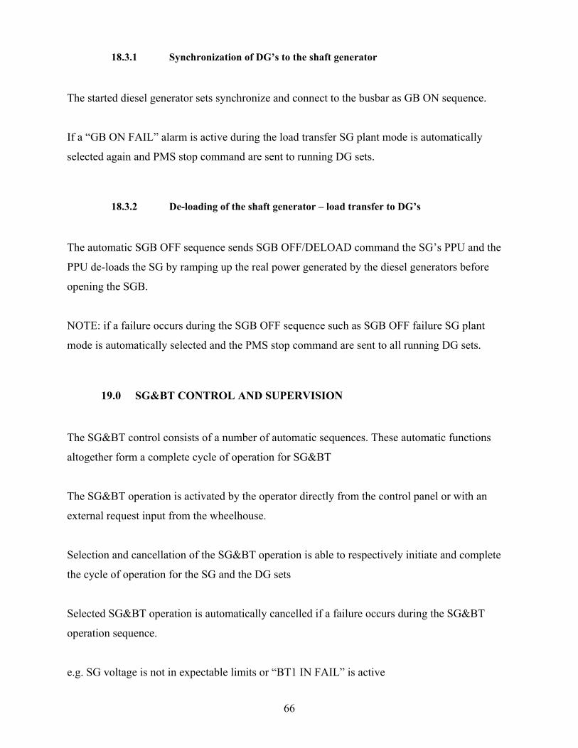
18.3.1 Synchronization of DG’s to the shaft generator
The started diesel generator sets synchronize and connect to the busbar as GB ON sequence.
If a “GB ON FAIL” alarm is active during the load transfer SG plant mode is automatically
selected again and PMS stop command are sent to running DG sets.
18.3.2 De-loading of the shaft generator – load transfer to DG’s
The automatic SGB OFF sequence sends SGB OFF/DELOAD command the SG’s PPU and the
PPU de-loads the SG by ramping up the real power generated by the diesel generators before
opening the SGB.
NOTE: if a failure occurs during the SGB OFF sequence such as SGB OFF failure SG plant
mode is automatically selected and the PMS stop command are sent to all running DG sets.
19.0 SG&BT CONTROL AND SUPERVISION
The SG&BT control consists of a number of automatic sequences. These automatic functions
altogether form a complete cycle of operation for SG&BT
The SG&BT operation is activated by the operator directly from the control panel or with an
external request input from the wheelhouse.
Selection and cancellation of the SG&BT operation is able to respectively initiate and complete
the cycle of operation for the SG and the DG sets
Selected SG&BT operation is automatically cancelled if a failure occurs during the SG&BT
operation sequence.
e.g. SG voltage is not in expectable limits or “BT1 IN FAIL” is active

67
19.1 SG&BT operation during an on going AUTO or SECURED mode
NOTE: An active SG&BT operation blocks for SG mode.
SELECTION OF SG&BT
OPERATION
SHAFT GENERATOR
VOLTAGE OK?
BTI IN SEQUENCE
OPERATION: LOAD
CONTROL
CANCELLATION OF SG&BT
OPERATION
BT1 OFF SEQUENCE
“READY FOR SG&BT MODE”
SG EXCITATION OFF SEQUENCE
FAILURE!
FAILURE!
CANCELLATION OF SG&BT
OPERATION
68
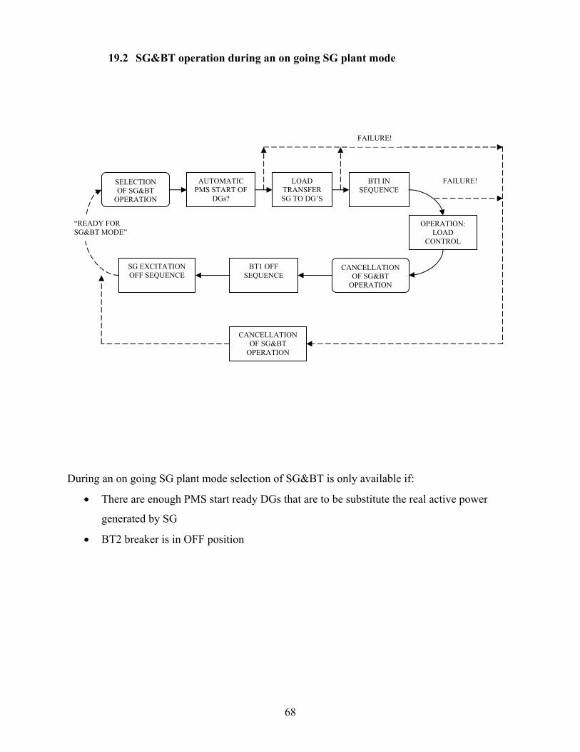
19.2 SG&BT operation during an on going SG plant mode
During an on going SG plant mode selection of SG&BT is only available if:
• There are enough PMS start ready DGs that are to be substitute the real active power
generated by SG
• BT2 breaker is in OFF position
SELECTION OF SG&BT
OPERATION
AUTOMATIC PMS START OF
DGs?
BTI IN SEQUENCE
OPERATION: LOAD
CONTROL
CANCELLATION OF SG&BT
OPERATION
BT1 OFF SEQUENCE
“READY FOR SG&BT MODE”
SG EXCITATION OFF SEQUENCE
FAILURE!
FAILURE!
CANCELLATION OF SG&BT
OPERATION
LOAD TRANSFER SG TO DG’S

69
20.0 POWER TAKE HOME / PTI MODE
PTI mode is almost like AUTO mode.
• Load dependent start/stop functions are available for this mode.
• Conditional connections of heavy consumers are also available if the predicted available
power is above the programmed limit.
When an external PTI mode request signal is received and if the SG is ready for PTI, PMS
controller immediately sends PMS start commands to the DGs.
Number of DG’s to be started and reserved for PTI mode is set under the window GENERAL
SYTEM CONFIGURATION.
In PTI mode the reserved DG sets are not included in the load dependent start/stop function but
the remaining DG set which are PMS start ready are included in load dependent start/stop
function. This means that during an on going PTI mode the programmed number of DGs in PTI
mode will be connected to the busbar and reserved for PTI at any time until the mode is
cancelled.
SELECTION OF PTI MODE
BLOCK LOAD DEPENDENT START/STOP
FUNCTION FOR THE DGs IN PTI
OPERATION: LOAD
CONTROL
CANCELLATION OF PTI
MODE
“READY FOR PTI MODE”
RETURN TO STANDART OPERATION
FAILURE! AUTOMATIC PMS START OF
DGs?
“PTI NOT READY” ALARM
REMOVE BLOCK FOR LOAD
DEPENDENT START/STOP FUNCTION
70
21.0 SUPERVISION OF THE SHORE CONNECTION
The PMS controller supervises the position of the shore connection breaker.
Once the ON status at the shore connection breaker is detected all automatic sequences for start
of the auxiliary engines are blocked.
• Load dependent start is blocked
• Blackout function is blocked
21.1 SWITCH OVER TO THE SHORE SUPPLY AND BACK
Following sequences are the possible suggestions on how to handle the switch over from dieasel
generator supply to shore supply and back.
21.1.1 Switching to shore supply from generator set supply
The operator may use the below described step by step procedure, when switching over from
diesel generator supply to the shore supply.
• Select SWBD control on all DG sets (both running and stand-by generators)
• Open all generator breakers via the switch board control
*** This will create a black-out situation but as long as all the DG sets are in SWBD
control blackout start sequence will not start and blackout start commands will not be set
to the DGs.
• Now turn the shore connection circuit breaker to ON position
*** The ON position of the shore connection breaker blocks for blackout start of the
generator sets.
• Select PMS control on all DGs again.
71
21.1.2 Switching from shore supply to generator set supply
The operator may use the below described step by step procedure, when switching over from
shore supply to generator supply.
1st scenario:
• Select PMS control on all DGs corresponding to generator sets which are desired to be
included PMS control.
• Turn the shore circuit breaker in to OFF position; this allows black0out start of the
generator sets
• When the black-out start sequence is completed normal automatic PMS control functions
are re established
2nd scenario:
• Select SWBD control on all DG sets
• Manually start the first two of the generator set according to the priority programmed
from the PMS controller side
*** Don’t close the breakers of the DG sets
• Select PMS control on all DGs or at least the running ones corresponding to generator
sets which are desired to be included PMS control.
• Turn the shore circuit breaker in to OFF position; this allows black0out start of the
generator sets
• When the black-out start sequence is completed normal automatic PMS control functions
are re established
72
3rd scenario:
• Select SWBD control on all DG sets
• Manually start the number of desired generator set(s) according to the priority
programmed from the PMS controller side
• Manually connect the DG set to the busbar
*** Blackout situation is disappears
• Select PMS control on all DGs or at least the running ones corresponding to generator
sets which are desired to be included PMS control.
• Turn the shore circuit breaker in to OFF position
• If not selected select the AUTO or SECURED mode from the control panel

73
22.0 TROUBLE SHOOTING
• Replace battery every 2 years or immediately when the BAT led on the power supply is in red color.
• Refer to PLC manual

74
75

76

77
78
79

80
81
82

83

84

85
86

87
TCP/IP SETTINGS FOR XXXXXX NBxxx-xxx
IP address
Subnet mask 255.255.0.0 PLC TCP/IP
CONFIGURATION Default gateway
IP address
Subnet mask 255.255.0.0 T-PANEL TCP/IP
CONFIGURATION Default gateway


![trtr trn tru tr[] ujosephschwartzdermatology.com/wp-content/uploads/... · trtr UEI trtr E] utr E] Y-ES tr tr B D tr tr tr tr tr NO tr EI tr u u u EI E tr OlherSystemic: Diobetes](https://img.pdfslide.us/doc/110x75/5f655dabeca5702d4204d061/trtr-trn-tru-tr-ujosep-trtr-uei-trtr-e-utr-e-y-es-tr-tr-b-d-tr-tr-tr-tr-tr-no.jpg)


![Revision and Exam Tips - New SMART website · =====trtrt]=-tr-trtrtrtrtrtr-tr F 1F]ilflfrritfltrft tr-trtr=tr tr=tr==tr tr-tlF-lflft 71 trtr=trtrtr=tr trtrtrtrtr=trtr trtrtrtrtr==tr](https://img.pdfslide.us/doc/110x75/5ed679a2e7ed90307a0783ea/revision-and-exam-tips-new-smart-trtrt-tr-trtrtrtrtrtr-tr-f-1filflfrritfltrft.jpg)