Embed Size (px)
Citation preview

STANDARDS/MANUALS/ GUIDELINES FOR SMALL HYDRO DEVELOPMENT
3.7 Electro-Mechanical– Technical Specifications for Procurement of Auxiliaries
Sponsor: Ministry of New and Renewable Energy Govt. of India
Lead Organization: Alternate Hydro Energy Centre Indian Institute of Technology Roorkee
November, 2012

Contact: Dr Arun Kumar Alternate Hydro Energy Centre, Indian Institute of Technology Roorkee, Roorkee - 247 667, Uttarakhand, India Phone : Off.(+91 1332) 285821, 285167 Fax : (+91 1332) 273517, 273560 E-mail : [email protected], [email protected]
DISCLAIMER The data, information, drawings, charts used in this standard/manual/guideline has been drawn and also obtained from different sources. Every care has been taken to ensure that the data is correct, consistent and complete as far as possible. The constraints of time and resources available to this nature of assignment, however do not preclude the possibility of errors, omissions etc. in the data and consequently in the report preparation. Use of the contents of this standard/manual/guideline is voluntarily and can be used freely with the request that a reference may be made as follows: AHEC-IITR,“3.7 Electro-Mechanical – Technical specification for procurement of auxiliaries”, standard/manual/guideline with support from Ministry of New and Renewable Energy, Roorkee, November 2012.

PREAMBLE
There are series of standards, guidelines and manuals on electrical, electromechanical aspects of moving machines and hydro power from Bureau of Indian Standards (BIS), Rural Electrification Corporation Ltd (REC), Central Electricity Authority (CEA), Central Board of Irrigation & Power (CBIP), International Electromechanical Commission (IEC), International Electrical and Electronics Engineers (IEEE), American Society of Mechanical Engineers (ASME) and others. Most of these have been developed keeping in view the large water resources/ hydropower projects. Use of the standards/guidelines/manuals is voluntary at the moment. Small scale hydropower projects are to be developed in a cost effective manner with quality and reliability. Therefore a need to develop and make available the standards and guidelines specifically developed for small scale projects was felt.
Alternate Hydro Energy Centre, Indian Institute of Technology, Roorkee initiated an
exercise of developing series of standards/guidelines/manuals specifically for small scale hydropower projects with the sponsorship of Ministry of New and Renewable Energy, Government of India in 2006. The available relevant standards / guidelines / manuals were revisited to adapt suitably for small scale hydro projects. These have been prepared by the experts in respective fields. Wide consultations were held with all stake holders covering government agencies, government and private developers, equipment manufacturers, consultants, financial institutions, regulators and others through web, mail and meetings. After taking into consideration the comments received and discussions held with the lead experts, the series of standards/guidelines/manuals are prepared and presented in this publication.
The experts have drawn some text and figures from existing standards, manuals, publications and reports. Attempts have been made to give suitable reference and credit. However, the possibility of some omission due to oversight cannot be ruled out. These can be incorporated in our subsequent editions.
This series of standards / manuals / guidelines are the first edition. We request users to send their views / comments on the contents and utilization to enable us to review for further upgradation.

Standards/ Manuals/Guidelines series for Small Hydropower Development
General 1.1 Small hydropower definitions and glossary of terms, list and scope of different
Indian and international standards/guidelines/manuals 1.2 Part I
Planning of the projects on existing dams, Barrages, Weirs
1.2 Part II
Planning of the Projects on Canal falls and Lock Structures.
1.2 Part III
Planning of the Run-of-River Projects
1.3 Project hydrology and installed capacity 1.4 Reports preparation: reconnaissance, pre-feasibility, feasibility, detailed project
report, as built report 1.5 Project cost estimation 1.6 Economic & Financial Analysis and Tariff Determination 1.7 Model Contract for Execution and Supplies of Civil and E&M Works 1.8 Project Management of Small Hydroelectric Projects 1.9 Environment Impact Assessment 1.10 Performance evaluation of Small Hydro Power plants 1.11 Renovation, modernization and uprating 1.12 Site Investigations Civil works
2.1 Layouts of SHP projects
2.2 Hydraulic design 2.3 Structural design 2.4 Maintenance of civil works (including hydro-mechanical) 2.5 Technical specifications for Hydro Mechanical Works Electro Mechanical works 3.1 Selection of Turbine and Governing System 3.2 Selection of Generators and Excitation Systems 3.3 Design of Switchyard and Selection of Equipment, Main SLD and Layout 3.4 Monitoring, control, protection and automation 3.5 Design of Auxiliary Systems and Selection of Equipments 3.6 Technical Specifications for Procurement of Generating Equipment 3.7 Technical Specifications for Procurement of Auxiliaries 3.8 Technical Specifications for Procurement and Installation of Switchyard
Equipment 3.9 Technical Specifications for monitoring, control and protection 3.10 Power Evacuation and Inter connection with Grid 3.11 operation and maintenance of power plant 3.12 Erection Testing and Commissioning

PERSON INVOLVED
1. Dr Arun Kumar, CSO & Principal Investigator, AHEC, IIT, Roorkee 2. Dr S K Singal, SSO & Investigator, AHEC, IIT, Roorkee Drafting Group 1. Mr. R.P.Goel, Consultant, Hardwar 2. Mr. S.K.Tyagi, Consultant AHEC, IIT, Roorkee Consultation Group 1. Dr Arun Kumar,AHEC,IIT, Roorkee 2. Mr S.N.Singh, AHEC,IIT, Roorkee 3. Dr S K Singal, AHEC,IIT, Roorkee 4. Prof. O.D.Thapar, Consultant AHEC,IIT, Roorkee 5. Mr. S.C.Jain, Consultant AHEC,IIT, Roorkee 6. Mr. Masum Ali, Consultant AHEC,IIT, Roorkee 7. Mr. A.K.Chopra, Consultant, SHP, MNRE,GOI, New Delhi 8. Mr. Jugal Kishore, , Consultant, Hardwar 9. Mr. S.V.Dinkar, Consultant, Pune 10. Mr. Surendra Singh ,PGCL, PEDA,Chandigarh 11. Mr. Pankaj Kulshreshtha, UJVNL, Dehradun 12. Mr. Himanshu Tiwari, UJVNL, Dehradun 13. Mr. A.K.Singh, UJVNL, Dehradun 14. Mr. P.K.Singhal, UPJVNL, Lucknow 15. Mr. V.K.Sharma, THDC, Rishikesh 16. Mr. U Ukhal, HPPCL, Himachal Pradesh 17. Mr..S.S.Sidhu, HPP India Pvt. Ltd, Noida 18. Mr. K.C.Arora, Pentaflo Hydro power Ltd 19. Mr. P.K.malohtra, Pentaflo Hydro power Ltd 20. Mr. Sanjeev Handu, Andriz Hydro power Ltd. 21. Mr. Vishnupad Saha, Andriz Hydro power Ltd. 22. Mr. Dinesh Rajput, Andriz Hydro power Ltd. 23. Mr. Pradeep Dube, Tanushree Hydropower Consultants, Noida 24. Mr. H.M.Sharma, Jyoti Ltd.,Vadodra 25. Mr. Viral B Mahida, Jyoti Ltd.,Vadodra 26. Mr. Nishant Saha, Jyoti Ltd.,Vadodra

CONTENTS
ITEMS PAGE NO Technical Specifications for Procurement of Auxiliaries 1.0 Introduction 1 1.1 Scope of Work 1 1.2 References 1
2.0 Specifications of Mechanical Auxiliaries 2 2.1 Overhead Travelling Crane 3 2.2 Drainage and Dewatering System 6 2.3 Cooling Water System 8 2.4 High Pressure and Low Pressure Compressed Air System 10 2.5 Water Level Measuring & Transmitting Device 12 2.6 Oil Filtration Unit (For Governor Oil) 13 2.7 Fire Protection Scheme 13 2.8 Ventilation and Air Conditioning 15
3.0 Specifications of Electrical Auxiliaries 16 3.1 Unit Auxiliary Transformers 16 3.2 Station Batteries, Battery Chargers and DC Board 17 3.3 LT AC Switchgear 19 3.4 Power, Control and Instrumentation Cables and Cable Laying
Equipment 22
3.5 Lighting System 26 3.6 Earthing and Lightning Protection 27 3.7 Internal Communication System 30 3.8 Transformer Oil Purifier (Optional) 31 3.9 Diesel Generating (DG) Set 31
4.0 Technical Parameters of Mechanical Auxiliaries of Power House
31
5.0 Technical Parameters of Electrical Auxiliaries of Power House 33
LIST OF TABLES
TABLE NO. TITLE PAGE NO. 1 Preferred number of air changes 16 2 Audible sound levels (dbA) for Dry Type Transformers 18 3 Other Particulars of Cables 23 4 Cable Laying 24 5 Details of Cable Trays, Support System and Pipes 25 6 Illumination Levels and Type of Fixtures and Luminaries 28 7 Minimum Conductor Size for Earthing System 30 8 Technical Parameters of Mechanical Auxiliaries of Power
House 31
9 Technical Parameters of Electrical Auxiliaries of Power House 33

AHEC-IITR/MNRE/SHP Standards/ E&M Works –Technical Specifications for Procurement of Auxiliary Equipment 1
TECHNICAL SPECIFICATIONS FOR PROCUREMENT OF AUXILIARIES
1.0 INTRODUCTION
1.1 Scope of Work
The scope of work includes design, material selection, manufacture, quality assurance, quality control, shop assembly and testing, transportation to site, insurance, storage at site, erection & commissioning of auxiliaries, field acceptance tests, warrantee and other services as specified or required for mechanical and electrical auxiliary systems selected/identified for Small Hydro Power stations. 1.2 References
R1 IEEE:142-2007 Recommended practice for grounding of industrial and commercial power systems
R2 IEC: 60947 4-1-2002 Contactors and motor-starters – electromechanical contactors motor-starters
R3 IEC: 60076-11:2004 Dry type transformers
R4 IEC 60754-1:2011 Test on gases evolved during combustion of materials from cables. Part 1:Determination of the amount of halogen gas
R5 IEC 60332-3-24:2008 Tests on electric cables under fire conditions . Part 3-24: Test for vertical flame spread of vertically-mounted bunched wires or cables
R6 ASTM D2863 - 12 Standard Test Method for Measuring the Minimum Oxygen Concentration to Support Candle-Like Combustion of Plastics
R7 ASTM D 2843-99 Standard Test Method for Density of Smoke from the Burning or Decomposition of Plastics
R8 NEMA Std. TR 1 Transformers, regulators and reactors
R9 IS: 2026-2006 Distribution transformers-method of construction
R10 IS:11171-2001 Specification for dry type transformer
R11 IS: 13947-2004 General requirements of Switchgear and Control gear for voltage not exceeding 1000 V ac.
R12 IS: 1652-2002 Plante Cells and batteries, lead acid type
R13 IS: 1651-2007 Tubular Cells
R14 IS: 8320 -2000 General requirement and method of tests for lead acid storage batteries
R15 IS: 1554 (Part-1)-2005
PVC insulated (heavy-duty) electric cables for working voltage up to and including 1100 V.
R16 IS: 1554 (Part-11)- 2005 PVC insulated (heavy-duty) electric cables for working voltage from 3.3kV up to and including 11 kV.
R17 IS: 7098(Part-11)-2005 Cross-linked polyethylene insulated PVC sheathed cables for working voltages from 3.3 KV up to and including 11 kV

AHEC-IITR/MNRE/SHP Standards/ E&M Works –Technical Specifications for Procurement of Auxiliary Equipment 2
R18 IS: 6380-2002 Specification of elastomeric insulation and sheathed electric cables
R19 IS: 9968-2005 Specification for elastomer insulated cables
R20 IS: 5831- 2001 PVC insulation and sheath of electric cables R21 IS: 3646-2003
Code of Practice for interior illumination (illumination glare index)
R22 IS:694-2005 PVC-insulated cables for working voltages upto 1100 V R23 IS: 732-2005 Wiring installation conditions R24 IS: 9537-2000 Specification for conduits for electrical installation R25 IS:8130-2001 Conductor for insulated electrical cables and flexible cords R26 IS: 3177-2003 Code of practice for Electrical Overhead Traveling
Cranes and Gantry Cranes R27 IS: 807-2006 Structural design of crane
R28 IS: 2189-2008
Code of Practice – Selection, Installation and Maintenance of Automatic Fire Detection and Alarm System
R29 IS: 3844-2000
Code of Practice for installation and Maintenance of Internal Fire Hydrants and hose reels on Premises
R30 IS: 4720-2003 Code of practice for ventilation of surface hydro power stations
R31 IS:4721-2000 Code of practice for drainage and dewatering of surface and underground hydro power stations
R32 IS: 3103-2004 Code of Practice for Industrial Ventilation R33 IS:2309-2005
Code of Practice-Protection of building and allied structure against lightning
R34 IS:3043-2001 Code of Practice for earthing in power plants R35 IS:2825-2002 Code for unfired pressure vessels R36 BS: 476: Part 8: 1972 Test Methods and Criteria for the Fire Resistance of
Elements of Building Construction
ABBREVIATIONS
ASTM : American Society for Testing and Materials BS : British Standards IEC : International Electro-technical Commission IEEE : Institute of Electrical & Electronic Engineers IS : Indian Standards NEMA : National Electrical Manufacturing Association
2.0 SPECIFICATIONS OF MECHANICAL AUXILIARIES
Mechanical auxiliary systems for different types of small hydro power stations comprise mainly the following:
(i) Overhead Traveling Crane
(ii) Dewatering and Drainage System, (iii) Cooling Water System with water pipe lines and valves. (iv) High Pressure Compressed Air System with air pipe lines and valves, (v) Water level sensing and transmitting device for fore bay and tail race.
AHEC-IITR/MNRE/SHP Standards/ E&M Works –Technical Specifications for Procurement of Auxiliary Equipment 3
(vi) Centrifugal type oil purifier unit for governor lubricating oil. (vii) Fire Protection System for generators, main transformers and other equipment of
power house (viii) Ventilation and Air conditioning
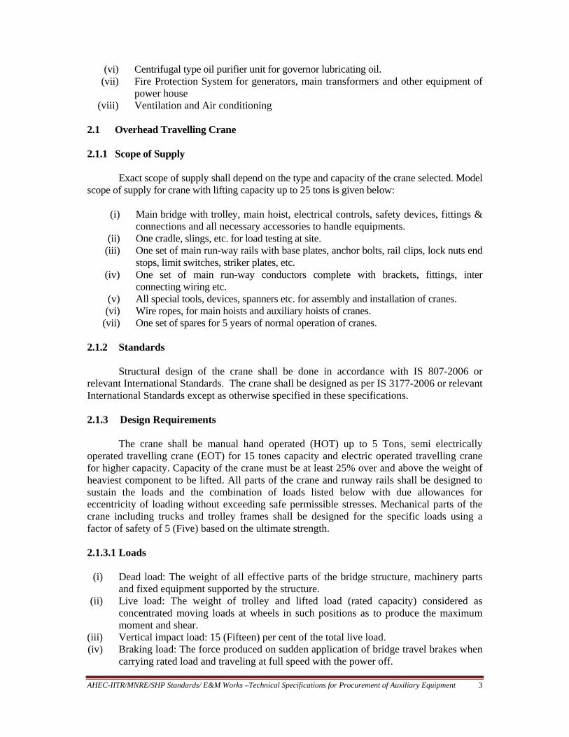
2.1 Overhead Travelling Crane 2.1.1 Scope of Supply Exact scope of supply shall depend on the type and capacity of the crane selected. Model scope of supply for crane with lifting capacity up to 25 tons is given below:
(i) Main bridge with trolley, main hoist, electrical controls, safety devices, fittings &
connections and all necessary accessories to handle equipments. (ii) One cradle, slings, etc. for load testing at site.
(iii) One set of main run-way rails with base plates, anchor bolts, rail clips, lock nuts end stops, limit switches, striker plates, etc.
(iv) One set of main run-way conductors complete with brackets, fittings, inter connecting wiring etc.
(v) All special tools, devices, spanners etc. for assembly and installation of cranes. (vi) Wire ropes, for main hoists and auxiliary hoists of cranes.
(vii) One set of spares for 5 years of normal operation of cranes.
2.1.2 Standards
Structural design of the crane shall be done in accordance with IS 807-2006 or relevant International Standards. The crane shall be designed as per IS 3177-2006 or relevant International Standards except as otherwise specified in these specifications. 2.1.3 Design Requirements
The crane shall be manual hand operated (HOT) up to 5 Tons, semi electrically operated travelling crane (EOT) for 15 tones capacity and electric operated travelling crane for higher capacity. Capacity of the crane must be at least 25% over and above the weight of heaviest component to be lifted. All parts of the crane and runway rails shall be designed to sustain the loads and the combination of loads listed below with due allowances for eccentricity of loading without exceeding safe permissible stresses. Mechanical parts of the crane including trucks and trolley frames shall be designed for the specific loads using a factor of safety of 5 (Five) based on the ultimate strength.
2.1.3.1 Loads
(i) Dead load: The weight of all effective parts of the bridge structure, machinery parts
and fixed equipment supported by the structure. (ii) Live load: The weight of trolley and lifted load (rated capacity) considered as
concentrated moving loads at wheels in such positions as to produce the maximum moment and shear.
(iii) Vertical impact load: 15 (Fifteen) per cent of the total live load. (iv) Braking load: The force produced on sudden application of bridge travel brakes when
carrying rated load and traveling at full speed with the power off.

AHEC-IITR/MNRE/SHP Standards/ E&M Works –Technical Specifications for Procurement of Auxiliary Equipment 4
(v) Lateral load due to trolley tractive effort: 10 (Ten) per cent of the sum of trolley weight and the rated crane capacity applied equally on the trolley rails.
(vi) Longitudinal load due to bridge tractive effort: 10 (Ten) per cent of the sum of the weight of crane and its rated capacity with the lifted load located at the extreme extent of travel of each end of bridge.
(vii) Earthquake load: Earthquake force to be taken equivalent to 0.3 g in horizontal direction and 0.14 g in vertical direction.
(viii) Other loads: Such as design floor load, special design load for horizontal frame design.
2.3.1.2 Combination of loads
Unless otherwise stated, the crane shall be designed to sustain the combination of
loads listed below without exceeding the safe permissible stresses.
(i) For crane in static hoisting position with dead load, live load and vertical impact load. (ii) For crane in motion with dead load, live load, and any one horizontal load listed under
lateral, longitudinal or specific design loads. (iii) For crane in motion with a combination of dead load and braking load. (iv) For crane in static position with dead load plus earthquake load. (v) For crane in motion with dead load, live load and any 2 (two) or more horizontal
loads listed under lateral longitudinal or special design loads with resulting unit stresses not more than 33-1/2 (Thirty three and one half) per cent in excess of safe stress.
(vi) For crane in static hoisting condition, with a combination of load and forces produced by the maximum or breakdown torque of the main hoist motor with resulting stresses not exceeding 90 (Ninety) per cent of the elastic limit of materials concerned.
2.1.4 Safety Requirements
In the design of crane, all safety regulations as applicable with factory acts, electricity rules etc., as prevailing in the country and at the site of installation shall be taken into consideration and provided for. 2.1.5 Performance Requirements
The crane shall be capable of raising, lowering, holding and transporting its rated load without any damage or excessive deflection of any crane component.
The following tolerances shall be maintained in the operation of the crane.
(i) Smooth control of vertical movement to within 3 mm with hook carrying rated load and all hoist brakes properly adjusted at normal operation.
(ii) Control of bridge and trolley motions to within 6 mm. (iii) The motor speed not to exceed 105 (One hundred and five) percent of synchronous
speed while lowering a rated load. (iv) The vertical deflection of crane girders caused by the rated load plus all dead loads
not to exceed 1/1000 of the crane span.

AHEC-IITR/MNRE/SHP Standards/ E&M Works –Technical Specifications for Procurement of Auxiliary Equipment 5
2.1.6 Technical Parameters The following requirements shall be met.
i. Main hoist rated capacity As required and should be approximate 25% over and above the weight of heaviest part to be lifted
ii. Auxiliary hoist rated capacity
1 T for 5 T capacity, 2 T for 10 T capacity 5 T for 15 T capacity and 20% of main hook for higher capacity cranes
iii. Main hoist normal speed 1.5/2.0 m/min iv. Auxiliary hoist speed 6.0/8.0 m/min v. Trolley travel speed 8/10 m/min
vi. Bridge travel speed 15/20 m/min vii. Travel of bridge Maximum possible
viii. Travel of trolley Maximum possible
The above parameters are tentative. The designer may choose different parameters depending upon the requirement of generating units. The creep motions of all movements shall be 10% of the main speed. 2.1.7 Electrical Connections and Motors
The main runway conductor system for supplying 415V-3 phase 4 wire 50 Hz power supply for the cranes shall consist of insulated rigid conductors, accessories and collectors. The conductor system for transmitting power and control commands to the trolley mounted equipment shall be of either festooned cable or insulated rigid conductors.
All motors shall be induction type with water tight terminals, antifriction bearings and built in totally enclosed fan ventilated enclosures. All motors speed shall not exceed 1500 rpm. Creep speed motors shall also be continuously rated. All travels and hoists shall be provided with at least two sets of brakes working on different principles viz. electromagnetic, thruster, eddy current braking system etc. All motions shall be provided with limit switches at both extreme ends of travel. 2.1.8 Controls Master controllers shall be located in the operator’s cabin. Indication and protections shall be provided on the control panel. 2.1.9 Hoisting Ropes, Hooks, Lifting Beam Hoisting ropes shall be extra flexible having a breaking strength at least five times that of the maximum working load. The crane shall be provided with a main hoist double hook of the rams horn type and the auxiliary hoist hooks of the single type with a safety latch. Main hook block shall incorporate a hole and pin for attaching lifting devices. All the hooks shall be 360o swivel type rotating on antifriction bearings.

AHEC-IITR/MNRE/SHP Standards/ E&M Works –Technical Specifications for Procurement of Auxiliary Equipment 6
2.1.10 Runway Rails
One set of runway rails and associated clamping devices with base plates, splice plates shall be included in the supply. 2.1.11 Walkways, Platforms & Lighting
Walkways, ladders, inspection platforms for allowing access to all parts of the crane shall be provided. Interior and exterior lighting inside the operators cabin and on bridge shall be provided. 2.1.12 Special Tools & Devices One set of all erection and maintenance tools special erection devices and testing devices shall be provided. The standard to be followed is IS 4721-2000 “Code of Practice for Drainage and Dewatering of Surface/ Underground hydro Electric Power Stations” 2.2 Drainage and Dewatering System 2.2.1 Scope of Supply
The requirement of drainage/dewatering system shall depend on the type and number of turbines used in the Power House. Usually, following equipment is required for the system:
(i) Vertical Turbine / Submersible Pumps for dewatering - one or
two sets (ii) Level Controller for dewatering pit. - one set
(iii) Vertical Turbine / Submersible Pumps for Drainage - two sets (iv) Level controller for drainage pit. - 1 set (v) Pipes, valves & fittings. - 1 lot
(vi) Special tools and devices for assembly / dismantling of pumps. (vii) One set of spares for five years operation
NOTE:
(i) Dewatering system may not be required for surface power houses having Pelton, cross flow, tubular and small horizontal Francis type of turbines.
(ii) Capacity of pumps shall be decided and given by the Purchaser as per requirement of individual power station.
2.2.3 Constructional Features 2.2.3.1 Dewatering System For dewatering the underwater parts, there shall be a sump whose bottom elevation will be sufficiently lower than the lowest point of the draft tube where the drain box is fitted to permit flow of water by gravity to the sump by opening a long spindle type gate valve provided at the sump. The dewatering will be done first by allowing the water in the penstock and spiral casing to flow into the tailrace through wicket gates till the water in the penstock reaches the tail water level and then by opening the drain valve in the sump for draft tube dewatering after
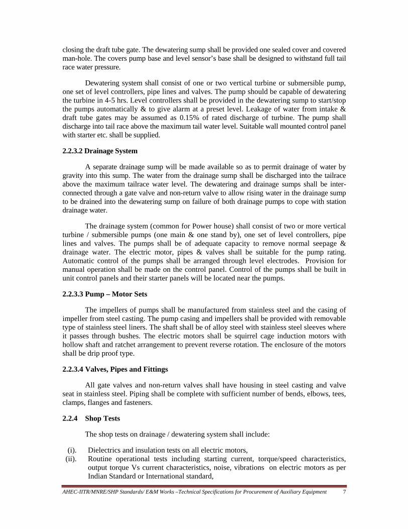
AHEC-IITR/MNRE/SHP Standards/ E&M Works –Technical Specifications for Procurement of Auxiliary Equipment 7
closing the draft tube gate. The dewatering sump shall be provided one sealed cover and covered man-hole. The covers pump base and level sensor’s base shall be designed to withstand full tail race water pressure. Dewatering system shall consist of one or two vertical turbine or submersible pump, one set of level controllers, pipe lines and valves. The pump should be capable of dewatering the turbine in 4-5 hrs. Level controllers shall be provided in the dewatering sump to start/stop the pumps automatically & to give alarm at a preset level. Leakage of water from intake & draft tube gates may be assumed as 0.15% of rated discharge of turbine. The pump shall discharge into tail race above the maximum tail water level. Suitable wall mounted control panel with starter etc. shall be supplied.
2.2.3.2 Drainage System
A separate drainage sump will be made available so as to permit drainage of water by gravity into this sump. The water from the drainage sump shall be discharged into the tailrace above the maximum tailrace water level. The dewatering and drainage sumps shall be inter-connected through a gate valve and non-return valve to allow rising water in the drainage sump to be drained into the dewatering sump on failure of both drainage pumps to cope with station drainage water.
The drainage system (common for Power house) shall consist of two or more vertical turbine / submersible pumps (one main & one stand by), one set of level controllers, pipe lines and valves. The pumps shall be of adequate capacity to remove normal seepage & drainage water. The electric motor, pipes & valves shall be suitable for the pump rating. Automatic control of the pumps shall be arranged through level electrodes. Provision for manual operation shall be made on the control panel. Control of the pumps shall be built in unit control panels and their starter panels will be located near the pumps.
2.2.3.3 Pump – Motor Sets
The impellers of pumps shall be manufactured from stainless steel and the casing of
impeller from steel casting. The pump casing and impellers shall be provided with removable type of stainless steel liners. The shaft shall be of alloy steel with stainless steel sleeves where it passes through bushes. The electric motors shall be squirrel cage induction motors with hollow shaft and ratchet arrangement to prevent reverse rotation. The enclosure of the motors shall be drip proof type.
2.2.3.4 Valves, Pipes and Fittings
All gate valves and non-return valves shall have housing in steel casting and valve seat in stainless steel. Piping shall be complete with sufficient number of bends, elbows, tees, clamps, flanges and fasteners. 2.2.4 Shop Tests
The shop tests on drainage / dewatering system shall include:
(i). Dielectrics and insulation tests on all electric motors, (ii). Routine operational tests including starting current, torque/speed characteristics,
output torque Vs current characteristics, noise, vibrations on electric motors as per Indian Standard or International standard,

AHEC-IITR/MNRE/SHP Standards/ E&M Works –Technical Specifications for Procurement of Auxiliary Equipment 8
(iii). Operational tests and tests for verification of Performance Characteristics offered of pumps as per Indian Standard/ International standard. Pumps will be tested with at least one actual motor tested and supplied for each type of pump motor set
(iv). Hydrostatic and leakage tests on all valves at 1.5 times the rated pressure. (v). Operational tests on level controllers
2.2.5 Field Tests
Following testes will be carried out at site after installation:
(i). Dielectrics and insulation tests on all electric motors, (ii). Operational tests on Pump Motor sets for determination of pump capacity, power
drawn at full discharge, vibrations and noise, (iii). Operational tests on Pump Motor sets for minimum 8 hrs continuous operation to
establish trouble free operation, (iv). Operational tests on control panels and instruments.
2.2.6 Drawings and Data
2.2.6.1 Following drawings and data shall be supplied with offer:
(i). Schematic drawing,
(ii). Typical General Arrangement Drawing of Pump – motor sets,
2.2.6.2 Following drawings and data shall be supplied after placement of order: (i). Schematic drawing, (ii). General Arrangement Drawing of Pump – motor sets, (iii). Catalogues of level controllers, (iv). Electrical Drawing of Control Panel, (v). O&M Manuals of Pumps (vi). QA Plan (vii). Layout and General Arrangement Drawings of the system showing details of pipes
and fittings and installation details of pump-motor sets.
2.3 Cooling Water System 2.3.1 Scope of Supply
The requirement and capacity of cooling water system shall be decided based on the type of turbine bearings, generator bearings and generator air cooling. Normally, following equipment is required in this system:
(i). Cooling Water Tapping arrangement from penstock - 1 for each unit
(ii). Pump Motor Sets - 1 set for each unit (iii). Duplex strainers - 1 set for each unit (iv). Necessary valves, pipes, supports etc. - lot (v). Spares for five years maintenance
(vi). Special tools and devices for assembly and installation

AHEC-IITR/MNRE/SHP Standards/ E&M Works –Technical Specifications for Procurement of Auxiliary Equipment 9
2.3.2 Constructional Features (i). Cooling Water Tapping: Cooling water shall be tapped from intake/spiral casing
with/without pressure reducer, with/without booster pumps or shall be lifted from tail race pool by vertical turbine/submersible pumps. The intake system shall be common for all the units and connected through isolating valves. If booster pumps are used, one main pump-motor set for each unit and one standby pump shall be used to supply adequate cooling water to generator air coolers and guide bearings of the units. The system shall provide 100 % redundancy operation of the unit pumps. Cooling water requirement of one unit shall be met by one pump. The standby pump shall be used in case of failure of any main pump. After pumps, the cooling water shall be passed through strainers and will be fed to each unit.
(ii). The pumps shall be centrifugal type directly driven by 3 phase 415VAC squirrel cage induction motors. The pump motor shall be mounted on common base plate. The impeller of pumps will be made in stainless steel, pump casing in steel casting and shaft in stainless steel. The discharge capacity of each pumps shall meet the total requirement of cooling water of one unit. If the water is lifted from tail pool, two nos vertical turbine or submersible pumps of suitable capacity shall be used.
(iii). Basket type duplex strainer with manual changeover of filter of discharge capacity 1 ½ times the pump discharge shall be provided after each pump to supply silt free clean water to various cooling circuits. The strainers shall be cleared off accumulated silt by dismantling the filter not in use or through backwash arrangement. Requirement of cleaning will be signalled through pressure differential switch.
(iv). Control of the pumps shall be built in Unit Control Panels and their starter panels will be located near the pumps.
(v). Valves, Pipes and Fittings: All gate valves and non-return valves shall have housing in steel casting and valve seat in stainless steel. Piping shall be complete with sufficient number of bends, elbows, tees, clamps, flanges and fasteners.
(vi). The duplex strainer shall be fitted with pressure switches to give alarm in case the pressure differential across it exceeds a pre-set value. Pressure gauges shall also be provided to indicate water pressure at its inlet and outlet.
2.3.3 Shop Tests
The shop tests on cooling water system shall include: (i). Dielectrics and insulation tests on all electric motors,
(ii). Routine operational tests including starting current, torque/speed characteristics, output torque Vs current characteristics, noise, vibrations on electric motors as per Indian Standard or International standard,
(iii). Operational tests and tests for verification of Performance Characteristics offered of pumps as per Indian Standard/ International standard. Pumps will be tested with at least one actual motor tested and supplied for each type of pump motor set
(iv). Hydrostatic and leakage tests on all valves at 1.5 times the rated pressure. (v). Operational tests of self cleaning strainers
2.3.4 Field Tests
Following testes will be carried out at site after installation:

AHEC-IITR/MNRE/SHP Standards/ E&M Works –Technical Specifications for Procurement of Auxiliary Equipment 10
(i). Dielectrics and insulation tests on all electric motors, (ii). Operational tests on Pump Motor sets for determination of pump capacity,
power drawn at full discharge, vibrations and noise, (iii). Operational tests on Pump Motor sets for minimum 8 hrs continuous
operation to establish trouble free operation, (iv). Operational tests on control panels and instruments, (v). Operational tests on self cleaning strainers.
2.3.5 Drawings and Data
Following drawings and data shall be supplied with offer: (i). Schematic drawing,
(ii). Typical General Arrangement Drawing of Pump – motor sets, (iii). Catalogues of strainers, (iv). Electrical Drawing of Control Panel.
Following drawings and data shall be supplied after placement of order: (i). Schematic drawing,
(ii). General Arrangement Drawing of Pump – motor sets, (iii). O&M Manual of Pumps and Strainers, (iv). Electrical Drawing of Control Panel, (v). Layout and General Arrangement Drawings of the system showing details
of pipes and fittings and installation details of pump-motor sets. (vi). QA Plan
2.4 High Pressure and Low Pressure Compressed Air System 2.4.1 Scope of Supply
This system is generally not required for SHP units up to approximately 1000 kW rating. For small and medium size power stations, compressed air system is required for governor oil pressure unit, generator braking and service air and consists of:
(i) Three Stage Reciprocating Compressors - 2 nos (ii) Moisture Separators - 2 nos (iii) High Pressure Air receiver - 1 no (iv) Low Pressure Air receiver (for Generator Brakes) - 1 no. (iv) Pipes, valves, instruments & fittings. - 1 lot 2.4.2 Constructional Features
(i). Compressed Air System shall be common for all the units. Two reciprocating
multistage compressors driven by electric motors shall be provided to feed compressed air in the air receiver. One of the compressors shall work as main and other as standby. Their operation shall be made automatic with the help of pressure switches. Compressed air after passing through air dryers shall be fed to one high pressure air receiver. One low pressure air receiver shall be provided for generator

AHEC-IITR/MNRE/SHP Standards/ E&M Works –Technical Specifications for Procurement of Auxiliary Equipment 11
brakes. Compressed air from high pressure air receiver shall be tapped and fed to low pressure air receiver through one pressure reducer.
(ii). Pressure rating of each compressor shall match maximum pressure requirement of governor oil pressure unit. Design calculation regarding compressor capacity and strength calculation of air receivers shall be submitted for approval of the Purchaser.
(iii). The compressors will be driven by 3 phase, 415 VAC completely enclosed, fan cooled, squirrel cage induction motors with class F insulation through belt and motor shall be mounted on a common base plate which shall be installed on floor with the help of foundation bolts.
(iv). Indian Standard IS 2825-2007 shall be followed for design, manufacture and testing of air receivers.
(v). The motor starter panel housing contactors, switch fuse units/MCB and meters etc shall be mounted on the wall near the compressors and wired complete with leads labelled. The connections to each motor shall be arranged so that either compressor may be removed for repair or replacement without interfering with the continuous operation of the other.
(vi). System design shall be subject to approval of the Purchaser.
2.4.3 Shop Tests
The shop tests on compressed air system shall include:
(i). Dielectrics and insulation tests on all electric motors, (ii). Routine operational tests including starting current, output torque v/s current
characteristics, noise, vibrations on electric motors as per Indian Standard or International standard,
(iii). Operational tests and tests for verification of Performance Characteristics of compressors as per Indian Standard/ International standard. Compressors will be tested with their respective motors.
(iv). Hydrostatic pressure tests on air receivers at 1.5 times the rated pressure. (v). Hydrostatic and leakage tests on all valves at 1.5 times the rated pressure.
(vi). Operational tests on pressure reducer.
2.4.4 Field Tests
Following testes will be carried out at site after installation:
(i). Dielectrics and insulation tests on all electric motors, (ii). Operational tests on compressors for minimum 8 hrs continuous operation to establish
trouble free operation without abnormal vibrations and noise, (iii). Operational tests on control panels and instruments.
2.4.5 Drawings and Data
Following drawings and data shall be supplied with offer:
(i). Schematic drawing, (ii). Typical General Arrangement Drawing of compressor set,
(iii). Typical General Arrangement Drawing of pressure receivers, (iv). Catalogues of compressor, moisture separator and pressure reducer.

AHEC-IITR/MNRE/SHP Standards/ E&M Works –Technical Specifications for Procurement of Auxiliary Equipment 12
(v). Electrical Drawing of Control Panel. Following drawings and data shall be supplied after placement of order:
(i). Schematic drawing, (ii). General Layout drawing of compressed air system showing details of pipes and
fittings and installation details of compressors, (iii). General Arrangement Drawing of compressor set, (iv). General Arrangement Drawing of pressure receivers, (v). O&M Manual of compressor, moisture separator and pressure reducer
(vi). Electrical Drawing of Control Panel, (vii). QA Plan (Approved by Purchaser)
2.5 Water Level Measuring & Transmitting Device 2.5.1 Scope of Supply Water level measuring & transmitting device for intake and tail race channel shall comprise of the following: (i). Level transducer with transmitting device for intake with complete mounting
arrangement, (ii). Level transducer with transmitting device for tail race with complete mounting
arrangement, (iii). Water level signals receiving and processing device with mounting arrangement, (iv). Interconnecting cables between sensors, transmitters and control unit. (v). Spares for five years operation 2.5.2 General Design and Constructional Requirements
(i). For monitoring water level upstream of intake gates, one set of suitable electronic
level sensor (strain gauge/capacitance/ultrasonic type) and transmitter unit shall be provided for transmitting the water level signal to controlling unit mounted in control & metering panels in control room. One set of identical level sensor and transmitter unit shall be provided for water level in tail race. The signals from both the units shall be analogue signals in the form of 4 to 20 mA. These signals shall be processed in centralized control unit. Necessary power supply to sensors and transmitting units shall be provided from control unit.
(ii). Output signals for fore-bay intake level, tail race level and their difference shall be provided from the control unit for further utilization in Governor electronic cubicle and SCADA. Digital indictors shall be provided in the control unit for indicating fore-bay level, tail race level and their difference i.e. gross head. The device should be of reliable make.
(iii). The level sensors shall be mounted inside a pipe in such a way that oscillations in water level are damped out and pipe do not get clogged by floating materials or silt etc. complete with mounting accessories.
(iv). Level sensors should be hermitically sealed and it should be possible to take out and calibrate them easily.

AHEC-IITR/MNRE/SHP Standards/ E&M Works –Technical Specifications for Procurement of Auxiliary Equipment 13
2.5.3 Shop Tests Tests recommended by the manufacturer including functional tests.
2.5.4 Field Tests
Tests recommended by the manufacturer including functional tests. 2.5.5 Drawings and Data
Following drawings and data shall be supplied with offer:
(i). Detailed catalogue of the equipment (ii). General arrangement and installation drawing
Following drawings and data shall be supplied after placement of order:
(i). General arrangement and installation drawing (ii). O&M Manual
(iii). QA Plan
2.6 Oil Filtration Unit (for governor oil) 2.6.1 Scope of Supply (Required for 5000 kW and above unit capacity ) (i) Mobile type Centrifugal Separator for purifying - 1 no.
governor/lubricating oil (ii) Portable Oil Transfer Pump - 1 no.
2.6.2 General Requirements (i). Mobile type Centrifugal Separator for purifying governor/lubricating oil of adequate
capacity shall be supplied complete with suction filter, positive displacement motorised pumps, electric heater of minimum 5 kW capacity with thermostatic control, instruments and control panel etc.. The complete unit shall be mounted on MS fabricated trolley type base plate with coaster wheels and toeing bar. The separator bowl body, bowl hood and disc stacks shall be made from stainless steel.
(ii). The solid particles shall be removed down to Class 18/15 ISO 4406. (iii). Mobile transfer pump of capacity at least 2000 liters per hour for filling the clean oil in
drums shall be supplied. The pump shall be fitted with filter at the suction and necessary valves at pump outlet.
2.7 Fire Protection Scheme 2.7.1 General
The arrangements of fire protection in Power House and its switchyard has been divided under the following three groups: (i). Fire protection scheme for Generators.
(ii). Fire protection for generator transformers located in outdoor switchyard.

AHEC-IITR/MNRE/SHP Standards/ E&M Works –Technical Specifications for Procurement of Auxiliary Equipment 14
(iii). Fire protection of the area and equipment in power house not covered under above two groups.
The details of the equipment and method of fire fighting scheme for above referred
equipment/area shall be designed, manufactured, installed and commissioned generally as per the scheme. 2.7.2 Fire Protection Scheme for Generators
The fire extinguishing equipment for the generators shall be of CO2 release type system. In the event of fire occurring inside the generator, CO2 would be automatically released, by one or more of the smoke detectors provided in the generator air circuit. The system may also be operated manually from a conveniently approachable place. 2.7.3 Fire Protection Scheme for Transformers
The fire extinguishing equipment for the transformers shall be water sprinkler type - water tapped from intake/penstock. In the event of fire occurring in the transformer, water sprinkler system would be automatically initiated, by one or more of the smoke detectors provided in the transformer. The system may also be operated manually from a conveniently approachable place. 2.7.4 Fire Protection of other Areas
The remaining areas of the power house shall be provided with following fire fighting arrangements. 2.7.4.1 Fire detectors
The following locations of equipment shall be provided with fire/smoke detectors. These detectors shall be installed above the equipments. Specifications of Fire Detectors and Alarm system and their installation shall be as per IS: 2189-2008.
(i). Control room-above control/relay panels, battery chargers etc.
(ii). Switchgear room - LT and HV switchgear, generator terminal equipment, excitation panel etc.
(iii). Cable galleries (iv). Any other location deemed necessary.
The above detectors shall initiate alarm and indication in the fire alarm panel to be
installed in the control room. The indication shall identify the location of smoke/fire for taking corrective action. 2.7.4.2 Portable Fire Extinguishers
Various types of fire extinguishers of requisite capacity shall be located at appropriate locations in the power house as follows.
(i). CO2 type fire extinguishers 6 Nos. Control room, switchgear room
(ii). Foam type extinguishers 4 Nos. Near OPU, stores etc.

AHEC-IITR/MNRE/SHP Standards/ E&M Works –Technical Specifications for Procurement of Auxiliary Equipment 15
(iii). Dry chemical type extinguishers 6 Nos. Switchgear room, control room (iv). Inert gas clean agent system 5 Nos. General electrical installations
2.7.4.3 Fire Buckets and Hydrants
Fire buckets filled with sand shall be provided on covered steel stand in switchyard,
unloading bay and machine hall. Water pipe line shall be laid in machine hall and fire hydrant hose pipes shall be
provided at two different locations. The specification IS: 3844-2005 shall be adhered to for these works.
In Power Houses with roof above 15 meters high from generator floor (ground) or
with total floor area more than 1000 m2 high pressure internal hydrant system must be provided.
2.8 Ventilation and Air Conditioning
2.8.1 General
The purpose of providing Ventilation and Air conditioning in power house is to prevent temperature stratification, to remove contaminated air, to remove heat dissipated from various equipments/systems, to provide clean air and to provide outside air necessary for human comfort. Standards to be followed are IS: 3103-1975and IS: 4720-1982 2.8.2 Types of Ventilation
The type of ventilation desired should be specified in the specifications. Ventilation may be of following types:
(i) Natural by forces set in motion by the heat of sun and winds; (ii) Forced or artificial by extraction or propulsion.
In case of SHP below1000 kW unit capacity with no areas below water, natural
ventilation by providing exhaust fans may be provided. This is to be provided in building design itself. No separate ventilation system is required.
In case of SHP of above 1000 kW capacity and, where some of the working places are below tail water level completely underground forced ventilation system is provided. In such case, the quantity of air required for the power station building should be worked out from the number of air changes preferred for the various premises of the building as given in Table 1. 2.8.4 Air Conditioning
For SHP stations air conditioning is not required in machine hall or other working areas. Split type air conditioners may be provided for control room where PLC based control panels are installed and office space.

AHEC-IITR/MNRE/SHP Standards/ E&M Works –Technical Specifications for Procurement of Auxiliary Equipment 16
Table 1: Preferred Number of Air Changes
Power House Premise Preferred Air Changes Per Hour
Main generator room, dark room, light and heavy storage rooms, dewatering and drainage sumps, record room
2
Passage, approach gallery, pipe gallery, ventilation equipment room, governor gallery, cable gallery, dewatering drainage-pump room or gallery
4
Oil storage and oil purification rooms, service (pump ) gallery, oil sludge room, compressor room, terminal board room, machine shop, tool room, pipe shop, electrical laboratory, fan room, battery room, telephone and communication equipment room
6
Offices, reception room, toilets, and control room 8 3.0 SPECIFICATIONS OF INDIVIDUAL ELECTRICAL AUXILIARIES Electrical auxiliary systems for the powerhouse shall be as under:
(i). Auxiliary Transformers (ii). Station Batteries and Battery Chargers
(iii). L.T Switchgear (AC and DC) (iv). Power, Control and Instrumentation Cables and Cable laying material (v). Lighting System
(vi). Earthing and Lightning Protection (vii). Communication System
(viii). Transformer Oil Purifier ( Optional ) (ix). Personal Computer System (x). D.G. Set
3.1 Unit Auxiliary Transformers 3.1.1 Scope of Supply Epoxy cast resin/resin encapsulated air cooled, /oil filled – Nos. three phase transformer of desired capacity 50 Hz, 3.1.2 Codes and Standards IEC: 60076-11-2004 : Dry type power transformers IS: 11171 - 1985 : Specification for dry type transformers or relevant Indian or British Standards may be used for details. 3.1.3 General Requirements
(i). Type And Rating : Epoxy cast resin/resin encapsulated/oil filled air cooled type, three
phase unit, 50 Hz, transformer of desired capacity (ii). Reference Drawings to be provided by Purchaser :
a) Single Line Diagram

AHEC-IITR/MNRE/SHP Standards/ E&M Works –Technical Specifications for Procurement of Auxiliary Equipment 17
b) Protection and Metering - Single Line Diagram c) Auxiliary Power system – Single Line Diagram
(iii). Enclosure: Enclosure of a tested quality sheet steel of minimum thickness 3 mm shall
also accommodate cable terminations. The housing door shall be interlocked such that it should be possible to open the door only when transformer is off. The enclosure shall be provided with lifting lugs and other hardware for floor mounting.
(iv). Core: High grade non-ageing cold rolled super grain oriented silicon steel laminations. (v). Winding conductor: Electrolytic grade copper. Windings shall be of class F insulation.
(vi). Cable box as per relevant ISS. (vii). Fittings of auxiliary indoor transformers: All the required fittings of transformer shall be
provided and will be subject to approved of the purchaser. (viii). Tap changer: Off load tap changer shall be provided on the transformer.
(ix). Insulation level – Class ‘A’. (a) The transformer shall be capable of with standing the specified impulse test
voltage. (b) One minute power frequency Test voltage for which the transformer shall be
designed, should be specified. 3.1.4 Operating Conditions
(i). Loading Capability Continuous operation at rated kVA on any tap with voltage variation of 10% corresponding to the voltage of the tap as well as in accordance with IEC 60076-1993. / IS 2026-2006
(ii). Flux density (a) Not to exceed 1.6 Wb/ sq.m. at any tap position with +/-10% voltage variation
from voltage corresponding to the tap. Transformer shall also withstand following over fluxing conditions due combined voltage and frequency fluctuations.
(b) 110% for continuous rating. (c) 125% for a least one minute. (d) 140% for a least five seconds.
(iii). Noise level: Not to exceed values specified in NEMA TR-1 as shown in Table 2.
3.1.5 Tests
The transformer shall be subjected to all the relevant tests on works and site as per relevant IS/IEC and copies of the same shall be supplied the purchaser for approval. 3.2 Station Batteries, Battery Chargers and Dc Board 3.2.1 Scope of Supply The battery system shall meet the complete requirements for control, protection and interlocks, emergency DC drives, emergency lighting, annunciation and field flashing etc and SCADA system. The standards to be followed are IS: 1652-1984, IS: 1651-1979 and IS: 8320-2005

AHEC-IITR/MNRE/SHP Standards/ E&M Works –Technical Specifications for Procurement of Auxiliary Equipment 18
The following data should be specified:
(i). No of Battery sets : (ii). Type of Battery sets :
(iii). Nos and type of battery Charger : (iv). Voltage and AH rating of each battery set :
Table 2 : Audible sound levels (dbA) for Dry Type Transformers
Audible sound levels (dbA) for Dry Type Transformers
kVA For voltage class less than 1.2kV (NEMA Std
ST20)
Ventilated self cooled(AA)
(NEMA Std TR1)
Ventilated forced air cooled(FA)
(NEMA Std TR1) 10-50 51-150 151-300 301-500 501-700 701-1000 1001-1500 1501-2000 2001-3000 3001-4000 4001-5000 5001-6000 6001-7500
45 50 55 60 62 64 65 66 68 -- -- -- --
50 55 58 60 62 64 65 66 68 70 71 72 73
-- -- 67 67 67 67 68 69 71 73 74 75 76
For 7500 kVA and above consult Manufacturer Source: NEMA standards
3.2.2 Construction Features The batteries shall be VRLA (valve regulated lead-acid) type and high discharge capacity. Each battery shall have a static battery charger, rated to fully recharge the battery from a completely discharged condition in not more than ten (10) hours in boost charging mode. Each battery charger shall be capable of float charging the two batteries while supplying the normal voltage regulators and shall have following facilities.
(i). Manual selection facility for battery charging mode i.e. whether trickle or boost. (ii). Automatic and manual control of output voltage and current. Selector switch shall
be provided for auto/manual selection. Auto to manual changeover shall not result in any harmful surges.
(iii). Effective current limiting feature and filters on both input and output to minimise harmonics, RFT(radio frequency transient), EMT(electromagnetic transient etc.
(iv). When on automatic control mode during trickle charging, the charger voltage shall remain within 1% of set value for maximum permissible voltage, frequency and combined voltage and frequency variation on feeding system and dc load variation from zero to full load.
(v). Degree of protection shall be IP: 42. For chargers located in air conditioned areas, same may be IP: 31.

AHEC-IITR/MNRE/SHP Standards/ E&M Works –Technical Specifications for Procurement of Auxiliary Equipment 19
(vi). The rectifier shall utilise diode/ thyristors and heat sinks rated to carry 200% of the load current continuously. Temperature of heat sink shall not be permitted to exceed 850 C duly considering the maximum charger panel inside temperature.
(vii). Rectifier fuse and RC surge suppressor. (viii). Ripple content to be limited to 1% peak to peak.
(ix). All inter cell connectors and terminals shall be fully insulated/shrouded. Batteries and chargers shall be connected to DC distribution boards (DCDBs) through single core cables for each pole. The main HRC fuses on battery and charger output shall have alarm contacts. The battery fuse shall be located close to battery in the battery room. The DC systems shall be unearthed, and relays shall be provided for a sensitive earth fault detection and annunciation. The low/high voltage alarms, instruments for indication of charger current and voltage, dc voltage, battery current, etc. shall also be provided. 24 V DC distribution boards along with all ACB, MCCB, CTs, switches, wiring, instruments and relays etc. ( in accordance with Purchaser’s Drawing) shall be supplied 3.3 L.T. AC Switchgear 3.3.1 Scope of Supply 415 V AC L.T distribution boards along with all ACB, MCCB, CTs, switches, wiring, instruments and relays etc. (in accordance with Purchaser ’s Drawing). Standards to be followed are IEC: 60947-2009 and IS: 13947-2004.
3.3.3 Constructional Features
(i). All 415 VAC switchgear, motor control centres (MCCs), AC Unit boards, unit
station/distribution boards (DBs), etc. shall be of metal enclosed, indoor, floor mounted and free standing type. The switchgear/MCCs shall be fully draw out type. However, distribution boards may be of fixed type construction.
(ii). The incomer and bus coupler breakers for switchgear shall be electrically operated with over current releases or relays. Paralleling of two supplies shall be avoided by interlocking, Auto-changeover scheme shall be provided for loss of supply to one section of bus. Provision for manual operation and changeover shall be included. Incomers for MCCs and DBs can be load break isolators.
(iii). For small motors switch-fuse contractor feeders shall be provided. The other outgoing feeders would be moulded case circuit breakers.
(iv). All frames and load bearing members shall be fabricated using mild steel structural sections or pressed and shaped cold rolled sheet steel of thickness not less than 3 mm. Frame shall be enclosed in cold rolled sheet steel of thickness not less than 1.3 mm. Doors and covers shall also be cold rolled sheet steel of thickness not less than 2 mm. Stiffeners shall be provided wherever necessary. Removable gland plates of thickness 3mm (hot/cold rolled sheet steel) or 3.2 mm (non-magnetic material) shall be provided for all panels.
(v). All switchboards/panels shall be of dust and vermin proof. All cut outs shall have synthetic rubber gaskets.

AHEC-IITR/MNRE/SHP Standards/ E&M Works –Technical Specifications for Procurement of Auxiliary Equipment 20
(vi). Where breaker/starter module front serves as compartment cover, suitable blanking covers, one for each size of panel per switchboard shall be supplied for use when carriage is withdrawn.
(vii). All switchboards, MCCs and DBs shall have following distinct vertical sections:
(a) Completely enclosed bus bar compartment for horizontal and vertical bus bars.
(b) Completely enclosed switchgear compartment, one for each breaker, motor starter or MCCBs.
(c) Compartment, alley or cable box for power and control cables where ever necessary shall be provided. In case of cable box, they shall be segregated with complete shrouding for individual feeders at the rear for direct termination of cables. For breaker cable connections, a separately enclosed cable compartment shall also be acceptable. It should be possible to carryout maintenance on a feeder with adjacent feeders alive.
(d) Compartment for relays and other control devices associated with a circuit breaker, wherever necessary shall be provided.
(viii). MCCs and DBs shall be divided into vertical sections. Each vertical section shall be
provided with adequately sized cable alley covering entire height. In case cable alleys are not provided for DBs, segregated cable boxes with complete shrouding of individual feeders shall be provided at the rear for direct termination of cables in each individual feeder.
(ix). Busbars shall be of high conductivity aluminium alloy. Minimum air clearance in air between phases and phase-earth shall be 25mm. For all other components, the clearances shall be at least 10 mm. All connecting strips horizontal and vertical busbars, insulation shall be provided by sleeving or barriers. In case of DC distribution boards/fuse boards, the busbar system shall be insulated or physically segregated with barriers to prevent interpole short circuit.
(x). Busbar insulators shall be of track-resistant, high strength, non-hygroscopic, non-combustible type and suitable to withstand stresses due to over-voltages and short circuit current. Insulators and barriers of inflammable material such as Hylam shall not be accepted.
(xi). Control circuits shall operate at suitable voltage of 24 V DC. Necessary control supply transformers having primary and secondary fuses shall be provided for each MCC, 2x100% per section. The auxiliary busbars for control supply shall be segregated from main bus bars. The control supplies shall be monitored.
(xii). Supplier shall fully coordinate overload and short circuit tripping of breakers with upstream and downstream breakers/fuses/MCCBs/motor starters. Various equipment shall meet requirement of Type-II class coordination as per IEC.
(xiii). Suitable trolley arrangement shall be provided for breaker modules. Two trolleys per switchgear room shall be provided so that top most breaker module of all types, sizes and rating can be withdrawn on trolley and lowered for maintenance purpose.
(xiv). All non-current carrying metal works of boards/panels shall be effectively bonded to earth bus of galvanised steel extending throughout the switchboard/MCC/DB. Positive earthing shall be maintained for all positions of chassis and breaker frame.
(xv). The circuit breakers shall be air break, three pole, spring charged, horizontal drawout type, suitable for manual and electrical operation, and shall have inherent fault making and breaking capacities. They shall have shunt trip coil. In case releases are offered, the same shall have contact for energisation of lockout relay. It shall have

AHEC-IITR/MNRE/SHP Standards/ E&M Works –Technical Specifications for Procurement of Auxiliary Equipment 21
anti-pumping feature. All breakers shall have built in interlocks for equipment and personnel safety.
(xvi). Mechanical tripping shall be through red `Trip' push buttons outside the panel for breakers, and through switches for other circuits. Clear status indication for each circuit shall be provided through lamps, switch positions or other mechanical means. Provision of mechanical closing of breaker only in `Test' and `Withdrawn' position shall be made. Alternatively, mechanical closing facility should be normally inaccessible, accessibility rendered only after deliberate removal of shrouds.
(xvii). Motor starter contactors shall be of air break, electromagnetic type as per IS: 13947 -2004 Part-4, section-1 suitable for DOL starting of motors, and shall be of utilisation AC-3 for ordinary and AC-4 for reversing starters. DC contactors shall be of DC-3 utilisation category.
(xviii). Fuses shall be HRC type with operating indicator. Isolating switches shall be of AC 23A category when used in motor circuit, and AC 22A category for other applications. Fuse switch combination shall be provided wherever possible.
(xix). Isolating switches and MCCBs shall have door interlocks and padlocking facility. All switchgear, MCCBs, DBs, panels, modules, local starters and push buttons shall have prominent engraved identification plates.
(xx). Local push button stations shall have metal enclosure of die cast aluminium or rolled sheet of 1.6 mm thickness.
(xxi). The temperature rise of the horizontal and vertical bus bars and main bus link including all power draw out contacts when carrying 90% of the rated current along the full run shall in no case exceed 550C with silver plated joints and 400C with all other types of joints over an ambient of 500C.
3.3.4 Relays and Protection (i). All types of relays and timers shall be subject to Purchaser's approval. They shall be
flush mounted with connections from inside, and shall have transparent & dust tight cover, removable from front, draw out construction for easy replacement and testing facility. The auxiliary relays and timers may be provided in fixed cases. All relays and timers shall operate on available DC supply and not have any inbuilt batteries. They shall be provided with hand-reset operation indicators (flags) or LEDs with push buttons for resetting.
(ii). All equipments shall have necessary protections. However, following minimum protections shall be provided.
(a) Motor feeders (motors rated up to 160 kW) (b) Instantaneous short circuit protection on all phases (c) Thermal overload protection (d) Single phasing protection for motors protected by fuses.
(iii). All meters/instruments shall be flush mounted on front panel, at least 72/96 sq.mm. size
with 90 degree line scales and accuracy class of 2.0. All motors of 10 kW and above shall have an Ammeter. Bus-sections have bus VT, voltmeter with selector switch, and other relays and timers required for protection. Adequate control and selector switches, push buttons and indicating lamps shall be provided. Thermostatic controlled space heaters with switches shall be provided to prevent condensation.

AHEC-IITR/MNRE/SHP Standards/ E&M Works –Technical Specifications for Procurement of Auxiliary Equipment 22
(iv). Current Transformers of required ratios shall be provided in the panels as per details in the protection scheme. CT cores; rated and type shall be subject to approval by Purchaser.
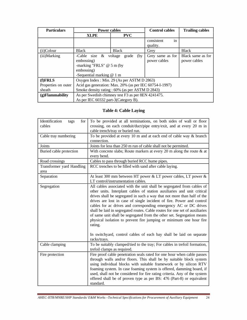
3.4 Power, Control and Instrumentation Cables and Cable Laying Equipment 3.4.1 Scope of Supply & Design Criteria These specifications covers the design, manufacture, shop testing before despatch, supply and delivery to site of power and control cables complete with junction boxes, terminal connections and materials required for cable laying etc., as specified hereunder. All equipments to be supplied under this head necessary to fulfil the purpose of the plant and to achieve proper operation of the required design conditions, even when some of the equipments are not expressively mentioned under the scope of supply & design criteria of this section. Standards to be referred are IS: 1554-2005, IS: 7098- 2005, IS: 6380-2006 and IS: 9968-2005. 3.4.2 General Requirements All cables shall be suitable for high ambient, high humid tropical Indian climatic conditions. All cables shall be Flame Retardant Low Smoke (FRLS) type designed to withstand the mechanical, electrical and thermal stresses under the foreseen steady state and transient/fault conditions, and shall be suitable for the proposed method of installation. For 3.3 kV cables, conductor screen and insulation screen shall both be extruded semi-conducting compound and shall be applied along with XLPE (Cross-linked poly ethylene) insulation in a single operation by triple extrusion process. Method of curing for 3.3 kV cables shall be “Dry curing/gas curing/steam curing". 3.3 kV cables shall be provided with copper metallic screen suitable for carrying earth fault current. For single core armoured cables, the armouring shall constitute the metallic part of screening. For 3.3 kV insulation shall be XLPE, while for other cables it shall be PVC (Poly vinyl chloride). For cables having more than five (5) cores, each core shall be identified by number marking. However, for cables up to five (5) cores, the same shall be by colour. Cables buried direct in ground and cables in switchyard shall be armoured. 3.3 kV able shall be unearthed grade. The cable shall withstand all the type tests routine tests and acceptance tests as per the latest editions of IS 8130 – 1976, IS 5831 – 1970 mentioned in IS 1554 (part I & II) – 1976. Some other particulars of the cables are as given in Table 3: 3.4.3 Cable Laying The complete cable support system shall be supplied and installed for the entire project. The system shall enable proper laying of all power, control, instrumentation and telephone cables, and shall provide necessary mechanical protection, ventilation and segregation for them. All hardware and anchoring arrangement shall be included. All steel members shall be hot dip galvanised. Laying of cables are given in Table 4.

AHEC-IITR/MNRE/SHP Standards/ E&M Works –Technical Specifications for Procurement of Auxiliary Equipment 23
Table 3: Other Particulars of Cables
Particulars Power cables Control cables Trailing cables XLPE PVC
(a) Conductor (i) Material Stranded Aluminium wire complying
latest edition of IS: 8130 - 1976 Stranded plain annealed copper
Tinned copper of class 5 of IS:8130-1976
(ii)Size As required Min. 6 sq.mm size As required, but min. 1.5 sq.mm.
As required, but min. 1.5 sq.mm
(iii)Shape Circular/ Sector shaped circular only for 3.3 kV cables
Circular/Sector shaped.
Circular Circular
(b) Main Insulation (i) Material XLPE PVC PVC insulation
shall be type I extended PVC 1.1 kV grade & free from voids
Heat resistant elastomeric compound based on ethylene propyline rubber (EPR)
(ii)Continuous withstand temperature (deg.C)
90 70 70 90
(iii)Short circuit withstand temp. (deg.C)
250 160 160 250
(iv)Colour identification
As pre relevant codes and standards
(c) Inner sheath All armoured and multi core un-armoured cables have distinct extruded inner sheath
(i) Material PVC PVC PVC extended type 6 PVC
Heat resistant elastomeric compound
(ii)Colour Black Black Black Black (d) Armour (i)Material Aluminium wire for single core cable
and GS wire/flat for multi core cables as per relevant IS. Minimum Coverage of 90%.
GS wire/flat as per relevant IS. Min. coverage of 90%
Nylon cord reinforcement
(ii)Breaking load of joint
95% of normal armour
95% of normal armour
(e) Outer sheath (i) Material (Polyethylene based halogen free material not acceptable)
PVC PVC PVC type 8 PVC with flame retardant low smoke (FRLS) properties. It should not stick to inner sheath &
Heat & oil resistant & flame retardant heavy duty elastomeric compound
AHEC-IITR/MNRE/SHP Standards/ E&M Works –Technical Specifications for Procurement of Auxiliary Equipment 24
Particulars Power cables Control cables Trailing cables XLPE PVC
consistent in quality.
(ii)Colour Black Black Grey Black (iii)Marking -Cable size & voltage grade (by
embossing) -marking "FRLS" @ 5 m (by embossing) -Sequential marking @ 1 m
Grey same as for power cables
Black same as for power cables
(f)FRLS Properties on outer sheath
Oxygen Index : Min. 29 (As per ASTM D 2863) Acid gas generation: Max. 20% (as per IEC 60754-I-1997) Smoke density rating : 60% (as per ASTM D 2843)
(g)Flammability As per Swedish chimney test F3 as per 8EN 4241475. As per IEC 60332 part-3(Category B).
Table 4: Cable Laying
Identification tags for cables
To be provided at all terminations, on both sides of wall or floor crossing, on each conduit/duct/pipe entry/exit, and at every 20 m in cable trench/tray or buried run.
Cable tray numbering To be provided at every 10 m and at each end of cable way & branch connection.
Joints Joints for less than 250 m run of cable shall not be permitted. Buried cable protection With concrete slabs; Route markers at every 20 m along the route & at
every bend. Road crossings Cables to pass through buried RCC hume pipes. Transformer yard Handling area
RCC trenches to be filled with sand after cable laying.
Separation At least 300 mm between HT power & LT power cables, LT power & LT control/instrumentation cables.
Segregation All cables associated with the unit shall be segregated from cables of other units. Interplant cables of station auxiliaries and unit critical drives shall be segregated in such a way that not more than half of the drives are lost in case of single incident of fire. Power and control cables for ac drives and corresponding emergency AC or DC drives shall be laid in segregated routes. Cable routes for one set of auxiliaries of same unit shall be segregated from the other set. Segregation means physical isolation to prevent fire jumping or minimum one hour fire rating. In switchyard, control cables of each bay shall be laid on separate racks/trays.
Cable clamping To be suitably clamped/tied to the tray; For cables in trefoil formation, trefoil clamps as required.
Fire protection Fire proof cable penetration seals rated for one hour when cable passes through walls and/or floors. This shall be by suitable block system using individual blocks with suitable framework or by silicon RTV foaming system. In case foaming system is offered, damming board, if used, shall not be considered for fire rating criteria. Any of the system offered shall be of proven type as per BS: 476 (Part-8) or equivalent standard.

AHEC-IITR/MNRE/SHP Standards/ E&M Works –Technical Specifications for Procurement of Auxiliary Equipment 25
3.4.3.1 General requirements (i). No sub zero level cable vault/trenches shall be provided below control
building/switchgear rooms in main plant and switchyard areas. (ii). Interplant cabling for main routes shall be laid along overhead trestles/duct
banks/directly buried. However, from tap-offs, same can be through shallow trenches with approval of Purchaser. Directly buried cable, if essential, shall not have concentration of more than four (4) cables. However, cables in switchyard area shall not be buried. Cables from main plant to switchyard control room shall be laid in duct bank/cable trenches.
(iii). In switchyard area, cables shall be laid in RCC concrete trenches. Wherever false floors are envisaged for cabling, the cables can be directly laid on ground, neatly routed along grid spacing. The false floor shall be at least 1000 mm deep. False floor requirement shall be subject to Purchaser’s approval.
(iv). Cable entry from outdoor underground/cable routes to the buildings, if any shall be above the finished floor level inside the building.
(v). PCC flooring of built up trenches shall be sloped for effective drainage with sump pits and sump pumps.
3.4.3.2 Cable trays, Support System and Pipes. Description of these are given in Table 5.
Table 5: Details of Cable Trays, Support System and Pipes
(a) Support system for cable trays
Prefabricated out of sheet steel and fully galvanised flexible type consisting of channels, cantilever arms and associated brackets & hardware, installed at site by bolting or clamping. These shall be rigid enough to withstand max. possible loads during and after installation.
(b) Type of cable trays Ladder for power cables and perforated for control instrumentation cables, complete with all accessories, fittings and hardware.
(c) Material of cable trays Rolled mild steel, min. 2 mm thick for trays and 3 mm thick for coupler plate.
(d) Finish of cable trays Hot dip galvanised. (e) Duct banks (if provided) Heavy duty GI pipes/heavy duty PE pipes (10% spare of each
size, subject to min one with suitable water-proof manholes. For corrosive areas, pipes shall have anti-corrosion coating both inside & outside.
(f) Pipe size Suitable with 40% fill criteria (g) Junction and Pull boxes Hot dip galvanised sheet steel of 2 mm thickness. (h) Cable glands Nickel-Chromium plated brass, heavy duty, single compression
type for unarmoured, and double compression type for armoured cables conforming to relevant Indian Standard
(i) Cable lugs Solder less tinned copper crimping type. For HT cables, lugs shall be as per DIN 46329. For rest, it shall be as per relevant IS.
(j) HT cable terminations and joints
Proven design and type tested as per VDE 0278. Elastimold or equivalent fully insulated moulded terminations shall be preferred.

AHEC-IITR/MNRE/SHP Standards/ E&M Works –Technical Specifications for Procurement of Auxiliary Equipment 26
3.5 Lighting System 3.5.1 Scope These specification covers design, manufacture, supply, installation, testing and commissioning of the lighting system at the project. The scope covers lighting arrangement for power house, switchyard, tail race, fore bay and other appurtenant works like bypass approach road and trash rack etc. Bureau of Energy efficiency, Govt. of India prescribed efficiency label product shall be used for most of the applications as far as possible. Standards to be followed are IS: 3646-2008, IS: 694-1990, IS: 732-2005 and IS: 9537-2006 3.5.2 General Requirements A comprehensive illumination system shall be provided in the entire project i.e. all areas within the plant boundary. The system shall include lighting fixtures, distribution boards, lighting panels, junction boxes, lighting poles, receptacles, switchboards, cables and wires, conduits, poles and masts, etc. The system shall cover all interior and exterior lighting such as area lighting, yard lighting, street lighting, security lighting, etc. 3.5.3 Design Criterion The illumination system shall be designed on basis of best engineering practice and shall ensure uniform, reliable, aesthetically pleasing, glare free illumination. The design shall prevent glare/luminous patch seen on VDU (visual display units) screens, when viewed from an angle. Power supply shall be fed from 240 V normal AC power supply, station service board, and DC supply for emergency lighting. Lighting panels shall be located at different convenient locations for feeding various circuits. These panels shall be robust in construction with lockable arrangements and individual MCB for different circuits. DC emergency lighting shall be provided in following areas: (i) Generator room -20 lux (ii) Operating floors of turbine hall -20 lux (iii) Switchgear room -15 lux (min. one lighting fixture between two rows of switchgear) (iv) Control and relay room -100 lux (v) Cable spreader room -at least 10% of illumination (min. one lighting fixture at convenient location.) (vi) Battery room -at least 10% of illumination (vii) Exit points and stair cases -One light fixture (Viii) All other strategic locations for safe personnel movement during any emergency. DC lighting shall switch on automatically on failure of normal AC supply. These shall be switched off automatically after the normal AC supply is restored and luminaries have attained their full glow. In off-site areas/buildings DC lighting is to be provided through self contained 4 hour duration fixtures located strategically. It shall be provided with Ni-Cd battery.

AHEC-IITR/MNRE/SHP Standards/ E&M Works –Technical Specifications for Procurement of Auxiliary Equipment 27
Lighting panels, fixtures, receptacles, poles, masts, distribution boards, switch boxes, conduits, junction boxes etc. shall be properly installed and earthed. All outdoor fixtures shall be weather proof type. Fluorescent fixtures, installed in other than control room areas shall have electronic ballasts. For control rooms, the ballasts shall be copper wound inductive, heavy duty type, filled with thermo-setting insulating moisture repellent polyester. All luminaries and their accessories and components shall be of the type readily replaceable by the available Indian makes. All fixtures and accessories shall be of reputed make and non-corrosive type. Acrylic covers/louvers shall be of non-yellowing type. Wiring shall be by multi-stranded PVC insulated colour code cable laid in GI conduits. Wiring for lighting circuits of AC, and DC systems shall be run in separate conduits throughout. Minimum size of the wire shall not be less than 1.5 sq. mm copper or 4 sq. mm aluminium. Wire shall conform to IS: 694-1990 and wiring installation shall be as per IS: 732-2005. Conduits shall be of heavy duty type, hot dip galvanised steel conforming to IS: 9537 Part3-1983. In corrosive areas, conduits shall have additional suitable epoxy coating. At least one 5/15A, 240 V universal socket outlet shall be provided in offices, stores, cabins, etc. 20A 240 V AC industrial type receptacles shall be provided strategically in all other areas. All these receptacles shall be 3 pin type and controlled with a switch. Suitable numbers of 63 A, 3 phase, 415 V AC industrial type receptacles with control switches shall be provided for the entire plant for welding purposes, particularly near all major equipment and at an average distance of 50 m. At least one 63 A receptacle shall be provided in each off-site building. Suitable number of ceiling fans in areas not covered by air-conditioning and ventilation system shall be provided. Street lighting shall be with swaged/steeped tubular steel poles of swan new construction. The poles shall be coated with anti-corrosive treatment and paint. All outdoor lighting systems shall be automatically controlled by synchronous timer or photocell. Arrangement shall be provided in the panel to bypass the timer/photocell for manual control. 3.5.5 Illumination Levels and Type of Fixtures and Luminaries These are given in Table 6. 3.6 Earthing and Lightning Protection 3.6.1 Scope
The specification covers design, supply, insulation, testing and commissioning of
earthing and lightning protection at the powerhouse and switchyard.
3.6.2 Design
The contractor shall furnish detailed design and calculation for Purchaser’s approval.

AHEC-IITR/MNRE/SHP Standards/ E&M Works –Technical Specifications for Procurement of Auxiliary Equipment 28
Table 6: Illumination Levels and Type of Fixtures and Luminaries
Location Average illumination level (Lux)
Glare index
Type of fixture
(i) Turbine Hall Operating floor (ii) Switchgear rooms (iii) Control room, computer room (iv) Offices, conference rooms etc. (v) Corridors (vi) Battery rooms (vii) Switchyard (viii) Compressor room, pump house, etc. (viii) Turbine, auxiliaires like OPU etc. (ix) Cable galleries (xi) Street lighting roads (xii) Outdoor storage handling (xiii)Permanent stores (xiv) Workshop, general work bench (xv) Laboratory - General -Analysis area (xvi) Garage/Car parking
200 200 300 300 70 100 10(general) 50(on equip.) 150 150 50 20 20 150 150 150 300 70
- - 19 19 16 - - - - - - - - - 25 19 19 -
HPSV high/medium bay Industrial trough type fluorescent Mirror optics with anti-glare feature Decorative mirror optics type -Do- Totally enclosed corrosion resistant / vapour proof. HPSV flood light, weather proof HPSV medium bay/industrial trough type fluorescent Flame proof fluorescent fixtures suitable for hazardous area Industrial trough type fluorescent HPSV street lights HPSV flood light, weather proof. Industrial trough type fluorescent Mirror optics fluorescent Corrosion resistant, vapour proof fluorescent Industrial trough type fluorescent
3.6.3 Earthing/Grounding Earthing system shall be designed as per IS: 3043-2004. The earth resistance of the earth mats for the P.H. and switchyard will be of the order of 0.5 ohms and 1 ohm respectively. The two mats will be joined together through 3 parallel conductors of the same cross section as those of conductors used in the mats. Earthing system network/earth mat shall be interconnected mesh of mild steel rods buried in ground in the plant. All off-site areas shall be interconnected together by minimum two

AHEC-IITR/MNRE/SHP Standards/ E&M Works –Technical Specifications for Procurement of Auxiliary Equipment 29
parallel conductors. The contractor shall furnish the detailed design and calculations for Purchaser's approval. Contractor shall obtain all necessary statutory approvals for the system. Enclosures of all electrical equipment as well as all cabinets/boxes/panels/etc. shall be earthed by two separate and distinct earth connections. Metallic pipes, conduits, cable tray section, etc. shall be bonded to ensure electrical continuity and earthed at regular intervals as well as at both ends. Metallic conduits, pipes, etc. shall not be used as earth continuity conductor. All hinged doors shall be earthed by flexible braids of adequate size. All steel structures shall be duly earthed. Metallic sheaths and armour of all multicore cables shall also be earthed at both equipment and switchgear end. Earthing conductor shall be buried at least 2000 mm outside the fence of electrical installations. Every alternate post of the fences and all gates shall be connected to earthing grid by one lead. Earthing conductor embedded in the concrete floor shall have at least 50 mm concrete cover. Earthing connections with equipment earthing pads shall be bolted type with at least two bolts, and joint surfaces shall be galvanised. The connections shall be painted with anti-corrosive paint after testing and checking. Neutral of power transformers shall be directly connected to two rod electrodes in treated earth pits, which in turn shall be connected to station earthing grid. The earthing terminal of surge arresters and voltage transformers, and lightning protection down conductors shall also be connected to station earthing grid through separate rod electrode. 3.6.4 Lightning Protection The lightning protection system shall be designed as per IS: 2309-2005. It shall cover all buildings and structures in the plant, and switchyard areas. It shall comprise horizontal/vertical air terminations, down conductors, test links and earth connections to the station earthing grid. All conductors shall be of minimum 25x6 mm size and shall be of galvanised steel only. The down conductors of lightning protection system shall have a test joint at about 1500 mm above ground level. Each down conductor shall be connected to a 40 mm dia, 3 m long mild steel earth electrode as well as station earthing grid. The lightning protection system shall not be in direct contact with underground metallic service ducts and cables, and shall not be connected above ground level to other earthing conductors. All joints in the down conductors shall be of welded type. Pulser system for lightning shall not be accepted. Hazardous areas, handling inflammable/explosive materials and associated storage areas shall be protected by a system of aerial earths as per IEEE: 142-2007. Other requirements for earthing system are as follows:
(i). Standard/Code IS: 2309-2005 (ii). Earthing system life expectancy 40 years

AHEC-IITR/MNRE/SHP Standards/ E&M Works –Technical Specifications for Procurement of Auxiliary Equipment 30
(iii). System fault level 40 kA for one second (iv). Soil resistivity Contractor to measure at site at
min. 20 locations approved by Purchaser. (v). Min. steel corrosion rate 0.25 mm per year.
(vi). Depth of burial of main earth 600 mm below grade level; where it crosses conductor trenches, pipes, ducts tunnels, rail tracks, etc., it shall be at least 300 mm below them.
(vii). Conductor joints By electric arc welding, with resistance of joint not less than that of the conductor. Welds to be treated with red lead for rust protection and then coated with bitumen compound for corrosion protection.
The minimum conductor size for earthing system as given in Table 7:
Table 7: Minimum Conductor Size for Earthing System
Equipment Buried conductor Conductor above ground & in trenches
Main station grid 40 mm dia MS rod/ 20 mm dia Cu.
65x8 mm GS flat
Switchgear/MCC -- 65x8 mm GS flat 415 V distribution boards -- 50x6 mm GS flat HT motors -- 50x6 mm GS flat LT motors above 125 kW -- 50x6 mm GS flat LT motors - 25 to 125 kW -- 25x6 mm GS flat LT motors - 1 to 25 kW -- 25x3 mm GS flat Fractional HP LT motors -- 8 SWG GS wire Control panel & control desk -- 25x3 mm GS flat Push button & Junction box -- 8 SWG GS wire Cable trays, cols. & structures -- 50x6 mm GS flat Busduct enclosures -- 50x6 mm GS flat Rails & other metal parts -- 25x6 mm GS flat Eqpt. earthing for switchyard -- 75x12 mm GS flat and 50x6 mm
GS flat 3.7 Internal Communication System 3.7.1 Scope An electronic telephone exchange suitable for 10 subscribers shall be provided, installed and commissioned in the powerhouse with multiple floors and total generating capacity more than 5000 kW. The system is not required for smaller Power Houses with generating capacity less than 5000 kW. For such Power Houses dedicated Mobile Phones should be provided to operating staff at important locations. The subscribers shall be located at various vulnerable positions to facilitate the communication. Standard PVC cables shall be laid for these subscribers.

AHEC-IITR/MNRE/SHP Standards/ E&M Works –Technical Specifications for Procurement of Auxiliary Equipment 31
Some of the important locations for subscribers may be as follows: i) Control room ii) Switchgear room iii) Machine hall iv) Unloading/erection bay v) Switchyard vi) Fore Bay vii) Pump house viii) Security gates ix) Offices
3.8 Transformer Oil Purifier (Optional) One No oil purifier complete in all respect for centrifuging transformer oil shall be
supplied and commissioned for successful performance. The purifier shall be mounted on rubber pad wheels trolley and shall comprise of compressor systems, heater system, filter packs etc including all electrical switches, fuses, temperature controllers, indicating instruments and operating valves. This machine should be able to centrifuge the transformer oil as per relevant Indian standards. 3.9 Diesel Generating (DG) Set
One no. Diesel Generating Set of specified capacity shall be provided for meeting the
power requirement during isolation of the power station from the grid. The D.G. set shall be eco-friendly, silent and as per the relevant Indian Standard.
(i). Catalogue of DG set with detailed specifications shall be supplied along with
the offer/bid. (ii). Relevant number of copies of O&M Instruction Manual shall be provided with
the equipment. (iii). DG set shall be supplied with all functional tests and load tests done
successfully at works.
4.0 Technical Parameters of Mechanical Auxiliaries of Power House are given in Table 8
Table 8: Technical Parameters of Mechanical Auxiliaries of Power House
S. No Description Value (to be filled
by bidder) 1. A. Dewatering System
(a) No. of pumps (b) Type & make of pumps (c) Rating of each pumps (discharge, speed, head) (d) Diameter of impellor (e) Material of casing, shaft & impeller (f) Type, rating, speed and insulation type of motors (g) Type and make of level controllers (h) Pressure rating of valves used

AHEC-IITR/MNRE/SHP Standards/ E&M Works –Technical Specifications for Procurement of Auxiliary Equipment 32
S. No Description Value (to be filled by bidder)
B. Drainage System (a) No. of pumps (b) Type & make of pumps (c) Rating of each pumps (discharge, speed, head) (d) Diameter of impeller (e) Material of casing, shaft & impeller (f) Type, rating, speed and insulation type of motors (g) Type and make of level controllers (h) Pressure rating of valves used
2. Cooling Water System (a) Source of cooling water (Intake / tail race ) (b) No. of pumps (c) Rating of each pumps ( discharge, speed, head) (d) Diameter of impeller (e) Material of casing & impeller (f) Motor type, rating, speed & insulation (g) Type of starter for motors (h) Capacity & make of self cleaning strainers (i) Material and size of strainer element (j) Capacity & make of actuator for strainer (k) Pressure rating of valves (l) Materials of casing, valve seat & stem of valves
3. Compressed Air System (a) No. and capacity of compressors (b) Type & make of compressors (c) Rating of motor, speed & type of insulation (d) Working pressure (e) Volume of high pressure air receiver (f) Volume of low pressure air receiver (g) Test pressure for air receivers (h) Nos., type & make of pressure switches (i) Type & make of pressure reducer
4. Fore bay & tail race water level measuring device (a) Type / basic principle of head sensors (b) Output signals from sensors (c) Make
5. Electrically operated travelling (EOT) Crane (a) Span (b) Longitudinal Travel (c) Capacity of Main Hook (d) Capacity of Auxiliary Hook (e) Min. clearance of main hook from wall (f) Operating speed of :
(i). main Hook (ii). auxiliary hook
(iii). bridge travel (iv). trolley travel

AHEC-IITR/MNRE/SHP Standards/ E&M Works –Technical Specifications for Procurement of Auxiliary Equipment 33
S. No Description Value (to be filled by bidder)
(g) Rating of main hoisting motor (h) Rating of bridge travel motor (i) Rating of trolley travel motor (j) Height of Girder (k) Min. clearance of roof required above girder
rail level (l) Cross Section of rails (m) Maximum lift of heaviest part possible (n) Total weight of crane
6. Fire Extinguishing System 7. Largest Package for shipment
(i). Name (ii). Weight
(iii). Dimension (L x W x H)
8. Heaviest Package for shipment (i). Name
(ii). Weight (iii). Dimension (L x W x H)
5.0 Technical Parameters of Electrical Auxiliaries of Power House are as per Table 9
Table 9: Technical Parameters of Electrical Auxiliaries of Power House
S. No Description Value (to be filled by bidder)
1 Auxiliary Transformers (a) No. of transformer (b) Type and make (c) Continuous maximum rating (d) No. of phases (e) No. of windings (f) Normal ratio of transformation (g) Corresponding highest system voltage (h) Minimum withstand voltages :
full wave impulse induced voltage applied voltage
(i) Type of cooling (j) Maximum hotspot temp at CMR (k) Maximum temperature (Ambient air temperature 450C)
----------------kV ----------------kV ----------------kV ----------------kV ----------------xC ----------------0C

AHEC-IITR/MNRE/SHP Standards/ E&M Works –Technical Specifications for Procurement of Auxiliary Equipment 34
S. No Description Value (to be filled by bidder)
(l) Phase connections: 11 kV windings 415 V windings Vector group (m)Short circuit MVA available 11 kV terminals 415 V terminals (n)Impedance voltage at 750C and at (o)CMR ( % on HV base) :
Maximum at normal ratio
(p)Voltage control Total range of variation Ratio plus Ratio minus Number and size of steps
---------------MVA ---------------MVA ----------------% -----------------% -----------------% -----------------%
(q) General Maximum flux density in iron at normal voltage and frequency and at normal ratio. (i). Cores Tesla (ii) Yokes Tesla (iii) Magnetising current(approx)
-------------------%
(r) Guaranteed total losses at normal ratio, rated output, rated voltage, rated frequency and 750C average winding temperature
------------------kW
(s) Efficiency at normal ratio, rated voltage, Rated frequency 0.9 p.f. and 750C average Winding temperature for the output of; Full load 3/4 full load 1/2 full load 1/4 full load
------------------% ------------------% ------------------% ------------------%
(t) Resistance per phase of: H.V. winding L.V. winding (u) Reactance per phase of: H.V. winding L.V. winding
Ohms Ohms Ohms Ohms
(v) Regulation at 750C and normal ratio; At unity power factor At 0.9 lagging power factor
-------------------% -------------------%
(w) Details of construction (i) Types of winding HV LV

AHEC-IITR/MNRE/SHP Standards/ E&M Works –Technical Specifications for Procurement of Auxiliary Equipment 35
S. No Description Value (to be filled by bidder)
(ii) Type of insulation HV windings LV winding (iii) Type of insulation Tapings Taping connection (iv) Details of Bushing
2 D.C. Station Batteries (a) Manufacture (b) Type (a) Capacity 110 volts 48 volts 24 volts (b) No of Batteries 110 volts 48 volts 24 volts (c) Battery Charger
Make Type
3. L.T. Switchgear (A.C. and D.C.) (a) A.C distribution Board (i) Manufacture (ii) Type (iii) Rated Bus bar current (iv) Circuit Breaker Manufacture and type (v) Isolator manufacturer and types (vi) Details of relays (vii) Make (viii) Type (ix) Details and make of CTs:
(b) D.C. switchgear (i) Manufacturer (ii) Type (iii) Rated breaker current (iv) Circuit breaker manufacturer and type (v) Isolator manufacturer and type
4. Power and control cables For each type of cable separate details are to be given. (i) Manufacturer (ii) Continuous Current Rating (iii) Rated voltage (iv) Cable Type (PVC/SWA/PVC MIAC, XLPE, etc.) (v) Number of Cores
-------------------A -------------------V

AHEC-IITR/MNRE/SHP Standards/ E&M Works –Technical Specifications for Procurement of Auxiliary Equipment 36
S. No Description Value (to be filled by bidder)
(vi) Cross Section sectional area (vii) Core Material (viii) No. of strands/core (ix) Nominal strand diameter (x) Conductor Insulation -Material -Thickness
-------------------mm2 -------------------mm -------------------mm
(xi) Armour /material (xii) Armour wires diameter (xiii) Sheathing Material (xiv) Sheath thickness (xv) Completed cable - Diameter - Weight per meter - Max. drum length (xvi) Application (connected plant )
-------------------mm -------------------mm -------------------mm -------------------kg -------------------m
5. Lighting system (i) Lighting fitting (ii) Manufacturer and Types (iii) Power Point / Switch fitting manufacturer
6. Cabling Earthing and lightning protection (i) Make and type of cable supports (ii) Make and types of cable trays (iii) Earthing material (iv) Lightning protection
7. Communication system Internal Communication System (i) Make (ii) Type (iii) No. of subscriber