Embed Size (px)
Citation preview
Standards
&
Operating Rules
Los Angeles Model Railroad Society
Adopted February 4, 2003
LAMRS Operation Rules (2) 2/07/03
Table of Contents
INTRODUCTION .........................................................................................................................................4
PART 1. BASIC CONSTRUCTION ...........................................................................................................5
SECTION 1. PLANNING AND DRAWINGS ....................................................................................................5
SECTION 2. BENCHWORK ........................................................................................................................5
SECTION 3. ROADBED .............................................................................................................................5 A. SUB-ROADBED ..................................................................................................................................... 5
B. STRAIGHT SUB-ROADBED ................................................................................................................ 6
C. CURVED SUB-ROADBED ................................................................................................................... 6
D. VERTICAL CURVES ............................................................................................................................. 6
E. FINISHED ROADBED ........................................................................................................................... 6
F. ROADBED STANDARDS ..................................................................................................................... 7
PART 2. TRACKAGE .................................................................................................................................7
SECTION 1. RAIL AND TURNOUTS .............................................................................................................7 A. RAIL ....................................................................................................................................................... 7
B. TURNOUTS ............................................................................................................................................ 8
PART 3. SCENERY .....................................................................................................................................8
SECTION 1. CONSTRUCTION AND MATERIALS ...........................................................................................8
SECTION 2. SCENERY BREAKS ..................................................................................................................8
SECTION 3. SCENIC MATERIALS ...............................................................................................................9
PART 4. MOTIVE POWER AND ROLLING STOCK ...........................................................................9
SECTION 1. STANDARD GAUGE ................................................................................................................9 A. STEAM LOCOMOTIVES ...................................................................................................................... 9
B. DIESELS ............................................................................................................................................... 10
C. UNIT TRAINS ...................................................................................................................................... 10
D. WEIGHTS, STANDARDS and CERTIFICATION .............................................................................. 11
SECTION 2. NARROW GAUGE ................................................................................................................. 12 A. STEAM LOCOMOTIVES .................................................................................................................... 12
B. FREIGHT and PASSENGER CARS .................................................................................................... 13
SECTION 3. COLOR STANDARDS ............................................................................................................. 13 A. COLORS for GL&W ENGINES and ROLLING STOCK .................................................................... 13
B. COLORS for D&RGW Narrow Gauge ENGINES, STRUCTURES and ROLLING STOCK ............. 17
C. COLORS for Sequoia Pacific Lumber Company ENGINES and ROLLING STOCK ......................... 17
SECTION 4. SPEED CALCULATIONS ........................................................................................................ 18
PART 5. OPERATIONAL STANDARDS AND DESCRIPTIONS ....................................................... 19
SECTION 1: LAYOUT DESCRIPTION AND PURPOSE .................................................................................. 19
SECTION 2: OPERATIONS ....................................................................................................................... 20 A. GREAT LAKES & WESTERN ............................................................................................................ 20
C. DENVER & RIO GRANDE WESTERN .............................................................................................. 21
D. TRAINING, TESTING and CERTIFICATION REQUIREMENTS .................................................... 21
1. GREAT LAKES & WESTERN ............................................................................................................ 21
2. DENVER & RIO GRANDE WESTERN .............................................................................................. 22
E. TRAIN MOVEMENTS ......................................................................................................................... 23
F. END OF SESSION ............................................................................................................................... 23
G. COMMUNICATIONS .......................................................................................................................... 23
H. SCHEDULE CHANGES ...................................................................................................................... 23
I. OPERATIONS on the NARROW GAUGE or LOGGING RAILROADS ............................................ 23
J. DONATED ROLLING STOCK and LOCOMOTIVES ........................................................................ 24
K. COMPUTER DATABASE .................................................................................................................... 24
SECTION 3: RADIO COMMUNICATIONS ................................................................................................... 25 A. DEFINITIONS ...................................................................................................................................... 25
B. GENERAL RADIO PROTOCOL ......................................................................................................... 25
C. INITIAL CONTACT to DISPATCH by ROAD ENGINEER .............................................................. 25
D. DIALOG WHILE UNDER WAY ......................................................................................................... 25
E. DIALOG WITH A YARD .................................................................................................................... 26
LAMRS Operation Rules (3) 2/07/03
F. CLEARING BLOCKS .......................................................................................................................... 26
SECTION 4: PROCEDURE FOR FACILITIES SHUT DOWN ........................................................................... 27
PART 6. TESTING AND CERTIFICATION PROCEDURES ............................................................. 28
PART 7. APPENDIX .................................................................................................................................. 29
LAMRS Operation Rules (4) 2/07/03
INTRODUCTION
The LAMRS layout covers about 2,100 sq. ft . The mainline is approximately
700 feet long with a minimum radius of thirty inches. The layout also features a
HOn3 Narrow Gauge branch line with several hundred feet of track, with was
added in 1987. The wooden benchwork utilizes the standard open grid type
design. Code 83 flex track is laid on Tru-scale® roadbed, which is in turn laid
on spline sub-roadbed. The scenery on the GL&W is hard shell plaster. The
GL&W Railroad basically is a point-to-point layout. The single track mainline
runs between the hidden staging yards of Alamosa and Langevin.
In addition to the six mainline walk-around throttles and the two staging yards,
there are eight additional locations on the layout. They are Baldwin, Ford Yard,
Ford Yard Engine Facilities, Hannibal , and Itasca Logging, Harbor East, Harbor
West and Harbor Engine Facilities. The non-mainline throttles represent
distinct switching and operational areas and are operated with their own control
panels and power supplies, the GL&W dispatcher does not control them. When
necessary, the non-mainline throttles share joint use blocks/track with the
mainline dispatcher so that control of a train may be passed from a non-mainline
throttle to a mainline throttle. Ford Yard represents the halfway point between
the two staging yards and serves as the division point for the GL&W.
The mainline throttles used on the layout are cordless infrared throttles designed
and built by members of LAMRS. These throttles are controlled by a
computerized dispatching station. The dispatcher sits at the computer console
and directs rai lroad traffic via two-way radio to six train engineers. The
monitor screen controls train routing and switching. This unique software was
developed in 1995 by members of LAMRS.
The following pages spell out the recommended standards and practices for the
LAMRS layout, GL&W paint schemes, the requirements for operating on the
layout, and the rolling stock certification procedures.
LAMRS Operation Rules (5) 2/07/03
PART 1. BASIC CONSTRUCTION
SECTION 1. Planning and Drawings
A. A complete set of track drawings are to be submitted to the membership for approval. This
includes plans for new railroads as well as any additions to an existing railroad.
B. A complete set of electrical schematics, circuit descriptions and drawings are to be submitted
to the membership for discussion and approval before any electrical work is done to any part
of the layout.
SECTION 2. Benchwork
All benchwork is to be constructed using the ‘open grid frame’ or the ‘L-girder’ method,
from 1x4 Fir wood. The legs are to be made of 2x4 Fir wood, cross-braced and long way
braced with 1x2 Fir wood; which are affixed to the leg bottoms, no higher than 4 inches from
the floor. Triangular gussets made of ½” thick Fir plywood 10”x10” are to be placed
between the long way brace and the 2x4 leg. The legs are to be spaced 1/5th of the way in
from the ends of the ‘L-girders’ to give the best support. Four (4) legs placed in this manner
will support up to 16 feet of ‘L-girder’. The legs should be high enough to adjust the level of
the ‘L-girder’ and Joist, which is affixed to the top of the ‘L-girder’. After leveling the
framework, affixing the ‘L-girder’ to the legs at the desired height - typically 40 inches - and
the 1x3 Joists are affixed to the legs, the excess tops of the legs may be cut off. Both angle
flanges of the ‘L-girder’ are to be turned so as to face the outside of the bench-work when
affixed to the legs. Except for narrow benchwork, the spread of the legs should be 12 inches
LESS than the narrowest part of the benchwork; i.e. the 1x3 Joist should hang over the ‘L-
girder’ at least 6 inches on each side. The 1x3 Joists are now added one at a time as needed,
and where needed - typically at no more than 24-inch intervals - to avoid being
inconveniently placed, and wasting lumber. The 1x3 Joists are to be secured to the ‘L-
girder’, on their edge, with glue and #6 x 1-1/4” screws. One screw placed so as to go up
through the ‘L-girder’ flange first, and then into the edge of the Joist will be sufficient to
hold it in place.
SECTION 3. Roadbed
A. SUB-ROADBED
Sub-Roadbed is the foundation upon which the trackage is placed. A firm foundation is as
important as carefully laid track is to reliable operation. In addition to rigidity, sub-roadbed
structure should allow for easy blending of scenery to the track base, and allow for the
locating of such auxiliaries as switch machines, bridges and overpasses. It should be at least
¾” thick kiln dried White Pine, and wide enough to suit the track plan. A 3-inch width is
fine for single track, and a 6-inch width is good for double track set at 2-1/2 inch centers.
The sub-roadbed is elevated above the benchwork by means of Risers. The Risers should be
1x4 (3-1/2”) for single track, and 1x8 (7-1/2”) for double track, and of sufficient length so as
to hold the roadbed at the desired elevation and be fastened to the Joist. The Risers are then
fastened to the Joist using glue and #6 x 1-1/4” screws. Provisions for bridges should be
LAMRS Operation Rules (6) 2/07/03
made at the time the sub-roadbed in installed. If the abutment for a bridge is not more than 4
inches from a Riser, the sub-roadbed can be cantilevered. In this case, the scenery abutment
and the bridge itself are supported by the sub-roadbed. In ALL other cases, supports should
be added near the abutments. These supports can be additional Risers, supported either from
an added benchwork member or from a lower level of sub-roadbed. For deck plate-girder
bridges, particularly those with a ballasted floor, it is desirable to narrow down the sub-
roadbed to the width between the girders and leave the board continuous across the bridge.
B. STRAIGHT SUB-ROADBED
Straight Sub-Roadbed will be constructed from ¾” thick kiln dried White Pine, cut to the
appropriate lengths, and secured to each Riser with #6 x 1-1/4” screws. The joints of the
sub-roadbed can be made at the Risers with ‘Cap Strips’ screwed to each side of the Riser to
increase its effective width; or, by gluing and screwing a splice block under the two pieces of
sub-roadbed.
C. CURVED SUB-ROADBED
Curved Sub-Roadbed will be formed by using laminated strips of ¾” thick kiln dried White
Pine. These strips are made by ripping the White Pine into ¼” wide pieces. These strips are
then placed vertically - set on edge - and glued together side by side, on top of the Risers, to
the desired width. The laminated sub-roadbed may be used as the ‘Finished Roadbed’ if
desired, and may be spliced to the flat-board sub-roadbed when special requirements of
vertical curves combined with horizontal curves make 100% flat-board sub-roadbed
impractical. Splice blocks under the flat-board sub-roadbed are used to join it with the
laminated roadbed. If the laminate is to be used, insure that when it’s spliced together with
the flat-board sub-roadbed, it is higher than the flat-board. This way, when the ¼” ‘Tru-
Scale®’ milled roadbed is placed on top of the flat-board, the top surfaces of both are flush
across the tops - given a small amount for sanding or planing to make them smooth. If the
‘Tru-Scale®’ milled roadbed is not going to be used, make sure the tops of both the laminate
and the flat-board are sanded flush to accommodate FLAT track-work.
D. VERTICAL CURVES
Vertical Curves are formed by bending the flat-board sub-roadbed. Because of its rigidity the
¾” thick Pine will insure that the vertical curve will be gradual transition rather then stepped
in nature.
E. FINISHED ROADBED
Finished Roadbed on the Main Line shall be ‘Tru-Scale®’ milled straight roadbed for
straight sections and the milled flexible roadbed for curved sections. In yard areas, the track
shall be laid directly on the flat-board or plywood provided in those areas.
LAMRS Operation Rules (7) 2/07/03
F. ROADBED STANDARDS
1. The roadbed shall NOT be placed closer than 6 inches to ANY inside/outside wall.
2. The centerline measurement for ALL parallel tracks shall be 2-1/2 inches.
3. The foundation for trackwork in ALL yard areas shall be constructed from ¾” thick ACx
grade Douglas Fir plywood in 4’x8’ sheets, with 1/8” thick x 4’x8’ Lauan (Mahogany)
doorskin glued and nailed to the top. This 7/8” thick assembly is then secured to the basic
Riser and crosspiece supports off the benchwork.
4. Roadbed turnouts on the Main Line are to be cut in the configuration of a #8 frog, from
¾” thick white pine and inserted into and in line with the sub-roadbed.
5. The MINIMUM Main Line radius shall be 30 inches.
6. The Main Line grade shall not exceed 2%.
7. All roadbed for ‘set out’ tracks will be level.
8. A minimum of at least 8 inches of straight track is required when passing by ALL served
structures; i.e. DO NOT place any structure on a curved section of track.
9. Stub ends off the Main Line shall be at least 24 inches long past the frog of the turnout.
10. For passing sidings or setout tracks which go around, or feed any structure shall be made
from a single piece of white pine, wide enough to accommodate the trackage and the
structure. If the board is not wide enough to accommodate the track and structure, than
the structure(s) may be placed on a separate piece of ¾” thick Fir plywood. This shall be
edge-glued to the roadbed, and a splice block glued underneath so as to keep both pieces
flat and flush across the top.
PART 2. TRACKAGE
SECTION 1. Rail and Turnouts
A. RAIL
1. Standard gauge rails shall be ‘Shinohara’ (Walthers) Code 83, Nickel Silver, flex track.
2. Narrow gauge rails shall be ‘Shinohara’ (Walthers) or ‘Micro Engineering’ Code 70,
Nickel Silver, flex track.
3. All rails shall be spliced together using Nickel Silver rail jointers, which shall be soldered
on the outside of the rails. Solder materials are limited to non-acid flux solder paste and
60/40 Rosin Core solder.
4. All trackage shall be kept at least 4 inches from ANY edge of the layout.
5. All S-curves MUST be separated by a section of straight track at least 4 inches long.
6. All sections of flex track will be laid by at least 2-man crews, using the 'master' NMRA
track gauge to check for proper gauge of all flex track.
7. All flex track shall be affixed to the roadbed using a small amount of glue to hold it in
position, and then 'spiked' in place through the holes provided in the ties.
8. Ballasting of the flex track in all exposed areas shall be done ONLY after it has been
ascertained that ALL new or modified trackage is in perfect running order, and any
necessary corrections or changes have been made.
9. Easement templates are to be used for transitions between curved and tangent track.
10. All completed sections of track work are to be inspected and approved by the
Superintendent of Construction.
LAMRS Operation Rules (8) 2/07/03
B. TURNOUTS
1. All Main Line turnouts shall be ‘Shinohara’ (Walthers) Code 83, Nickel Silver, #8 frog.
2. All Yard turnouts shall be ‘Shinohara’ (Walthers) Code 83, Nickel Silver, #6 frog.
3. All HOn3 turnouts shall be ‘Shinohara’ (Walthers) or ‘Micro Engineering’ Code 70,
Nickel Silver, #6 frog - point type turnouts. No stub point type or #4 turnouts shall be
permitted.
4. All Risers shall be a minimum of 2 inches clear of any turnout switch point.
5. A 6" length of straight track will be required, leading into the points of all turnouts on the
Main Line, and a 4” section of straight track leading into the points of all Branch Line
turnouts.
6. The points of all facing turnouts shall be no closer than 6 inches.
7. Rail joiners splicing turnouts and flex track shall be soldered as cleanly as possible. File
smooth the top and insides of the web so as to create a smooth splice, thus, eliminating
the possibility of wheel flanges 'catching' on any rough solder joints.
8. No turnout shall be placed closed than 6 inches from the start of any rise in elevation
neither of trackage, nor from the entrance or exit of any tunnel.
9. The frog to point distance of all ladder track configurations, for turnouts, shall be placed
no closer than 4" from each other; i.e. - the points of a turnout must be at least 4" from
the frog of the preceding turnout.
10. Turnouts shall be electrically operated by utilizing "Switch-Master" or “Tortoise” 12VDC
powered switch machines.
PART 3. SCENERY
SECTION 1. Construction and Materials
A. Basic construction shall be 'contoured' chicken wire - or lath type screen - overlaid with
Hydracal ® (plaster) soaked paper towels.
B. Regular 10-30 minute casting plaster or equivalent shall be used for rock castings and other
such moldings as are necessary to complete the scenic effect.
C. Scenery shall be stained with a water base tinting color: i.e. - Sinclair Paints® 'All Tint'
universal concentrated tinting colors for paint. Only the following basic earth colors of Raw
Sienna, Burnt Sienna, Raw Umber, Burnt Umber, Van Dyke Brown, Lamp Black,
Ultramarine Blue, Yellow Ochre, and White shall be permitted.
D. The chicken wire - or lath type screen - shall be fastened to the roadbed with at least 1/2"
staples, and then 'drooped' in such a way as to form a ditch on each side of the roadbed.
E. Small 'knolls' and the like are not required to use chicken wire or cardboard under frame,
providing such scenery is placed on a flat surface. These ‘knolls’ and the like should be
formed by sifting dry casting plaster onto the flat surface until the desired shape and height is
obtained. The 'knoll' of dry plaster is then sprayed with a fine mist of water so as to set up
the plaster. In spraying water onto the dry plaster, small cracks will naturally form in the dry
plaster creating a rain-eroded look in the 'knoll'.
SECTION 2. Scenery Breaks
LAMRS Operation Rules (9) 2/07/03
A. Scenery breaks are to be constructed using 1/8" thick x 4' x 8' sheets of non-tempered
Masonite®.
B. Non-tempered Masonite® sheets of 1/8" thickness are to be used for the profile boards on the
outside edges of the layout, and will be painted with a Latex type paint, in a flat green color.
SECTION 3. Scenic Materials
A. Lichen of various colors shall be used for small brush, weeds, and small trees.
B. Pine trees will be made using dried Caspia and finely ground foam rubber for the boughs.
The trunks are to be made from regular Cedar shingles, cut to width, and then carved or
sanded into a rounded shape. Diameter of the trunks is typically 3/8" to 5/8". The length
shall be typically a HO Scale 80' to 120' - however pine trees do grow to heights in excess of
200 feet. Small holes are then drilled in the trunks, and then the boughs of Caspia are glued
into the holes. When the boughs are dry, cheap hair spray (containing Lacquer), or a spray
type adhesive, is sprayed at a downward angle so as to cover the tops of the boughs. Quickly
sprinkle the desired color of ground foam rubber on the wet adhesive. Repeat the process of
spray and foam rubber to ‘build-up’ the thickness of the boughs. Small commercially
manufactured trees may also be used for background effect.
C. Grass material will be the 'static grass’ available in a variety of colors, produced by various
manufacture’s, and is available in most hobby shops. Woodland Scenics® fine ground foam
grass may also be used, as well as their 'Earth Blend' ground foam. Real dirt (which has been
sifted clean) shall be used as much as possible - where dirt is required - to create as natural
looking scenery as possible.
D. Small, real pebbles and rocks will be used wherever applicable, i.e. streams or riverbeds,
rock slides, etc.
F. Water shall be made using clear resin. The basic lake, river, stream, pond, etc. shall be
formed via the chicken wire and plaster method. The plaster may be stained or painted to the
desired color, and then the clear resin is mixed per instructions, and poured over the colored
plaster. Use a cheap paintbrush to move the resin around to cover the area desired to create
the 'wet' effect. Small rocks, branches, etc. should be placed into the wet resin before it sets-
up.
PART 4. MOTIVE POWER and ROLLING STOCK
SECTION 1. Standard Gauge
A. STEAM LOCOMOTIVES
1. All steam locomotives (except Unit Train Engines) are required to have operating
magnetic Kadee couplers on both the pilot of the engine, and the rear of the tender. The
tender coupler must be insulated from the metal parts of the tender. In the event, a
coupler cannot be adapted to the pilot of a locomotive, then that locomotive must be
consisted with another locomotive and shall be the lead unit in the double head consist.
2. ALL steam locomotives will be tested for their tractive effort, at a designated club
meeting night, under the supervision of the Superintendent of Operations. Locomotives
and their tractive effort shall be cataloged and stored by road name and engine number on
the clubs computer data file by the Superintendent of Operations. The tractive effort shall
LAMRS Operation Rules (10) 2/07/03
be ascertained by using the chart at the end of this Section. (This chart needs to be
developed)
3. All locomotives will be re-inspected and re-tagged annually, in accordance with Part 4,
Section 1, Paragraph A, Item 2.
4. Members are solely responsible for the general maintenance and run ability of their own
equipment.
B. DIESELS
1. Diesel units may be draw bared, if so, those units shall be tested and classed as one unit
for the tractive effort rating.
2. Single or multiple units shall still be required to have operating magnetic couplers on
each end. The only exception to this rule will be the Unit Train classification. Passenger
locomotives having coupler cover plates, such as ‘E’ Units, must be consisted with
another powered locomotive.
C. UNIT TRAINS
1. All Unit Trains are to be cataloged as such, and will be required to comply with the
maintenance and run ability standards as follows.
2. A Unit Train shall be construed as locomotive(s) and either freight or passenger cars
attached to each other by means other than operating couplers. That is, by means of draw
bar or non-operating couplers only. Talgo trucks are not permissible.
3. The operation of such Unit Trains on the layout shall not in any way impair or slow any
existing operations by any other engine or train.
4. All Unit Trains are required to have one operating magnetic Kadee coupler on the last car
of that train.
LAMRS Operation Rules (11) 2/07/03
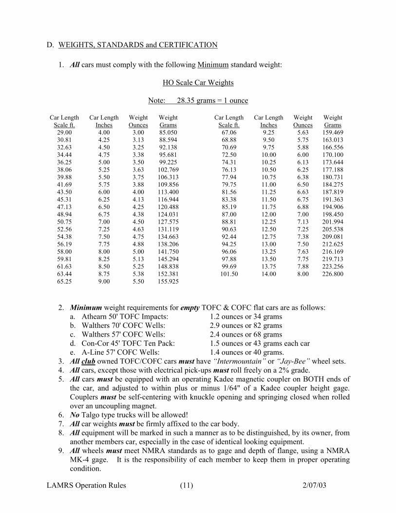
D. WEIGHTS, STANDARDS and CERTIFICATION
1. All cars must comply with the following Minimum standard weight:
HO Scale Car Weights
Note: 28.35 grams = 1 ounce
Car Length Car Length Weight Weight Car Length Car Length Weight Weight
Scale ft. Inches Ounces Grams Scale ft. Inches Ounces Grams
29.00 4.00 3.00 85.050 67.06 9.25 5.63 159.469
30.81 4.25 3.13 88.594 68.88 9.50 5.75 163.013
32.63 4.50 3.25 92.138 70.69 9.75 5.88 166.556
34.44 4.75 3.38 95.681 72.50 10.00 6.00 170.100
36.25 5.00 3.50 99.225 74.31 10.25 6.13 173.644
38.06 5.25 3.63 102.769 76.13 10.50 6.25 177.188
39.88 5.50 3.75 106.313 77.94 10.75 6.38 180.731
41.69 5.75 3.88 109.856 79.75 11.00 6.50 184.275
43.50 6.00 4.00 113.400 81.56 11.25 6.63 187.819
45.31 6.25 4.13 116.944 83.38 11.50 6.75 191.363
47.13 6.50 4.25 120.488 85.19 11.75 6.88 194.906
48.94 6.75 4.38 124.031 87.00 12.00 7.00 198.450
50.75 7.00 4.50 127.575 88.81 12.25 7.13 201.994
52.56 7.25 4.63 131.119 90.63 12.50 7.25 205.538
54.38 7.50 4.75 134.663 92.44 12.75 7.38 209.081
56.19 7.75 4.88 138.206 94.25 13.00 7.50 212.625
58.00 8.00 5.00 141.750 96.06 13.25 7.63 216.169
59.81 8.25 5.13 145.294 97.88 13.50 7.75 219.713
61.63 8.50 5.25 148.838 99.69 13.75 7.88 223.256
63.44 8.75 5.38 152.381 101.50 14.00 8.00 226.800
65.25 9.00 5.50 155.925
2. Minimum weight requirements for empty TOFC & COFC flat cars are as follows:
a. Athearn 50' TOFC Impacts: 1.2 ounces or 34 grams
b. Walthers 70' COFC Wells: 2.9 ounces or 82 grams
c. Walthers 57' COFC Wells: 2.4 ounces or 68 grams
d. Con-Cor 45' TOFC Ten Pack: 1.5 ounces or 43 grams each car
e. A-Line 57' COFC Wells: 1.4 ounces or 40 grams.
3. All club owned TOFC/COFC cars must have “Intermountain” or “Jay-Bee” wheel sets.
4. All cars, except those with electrical pick-ups must roll freely on a 2% grade.
5. All cars must be equipped with an operating Kadee magnetic coupler on BOTH ends of
the car, and adjusted to within plus or minus 1/64" of a Kadee coupler height gage.
Couplers must be self-centering with knuckle opening and springing closed when rolled
over an uncoupling magnet.
6. No Talgo type trucks will be allowed!
7. All car weights must be firmly affixed to the car body.
8. All equipment will be marked in such a manner as to be distinguished, by its owner, from
another members car, especially in the case of identical looking equipment.
9. All wheels must meet NMRA standards as to gage and depth of flange, using a NMRA
MK-4 gage. It is the responsibility of each member to keep them in proper operating
condition.
LAMRS Operation Rules (12) 2/07/03
10. Diaphragms between passenger cars are to be free sliding.
11. Run ability of any car shall not be beyond the reproach of a club member, who thinks it
questionable. In such a situation, the unit in question shall immediately be removed from
operation and tested. Any defects found shall be corrected, and the car must be re-
certified.
12. All cars with plastic wheels will be subject to an annual inspection and re-certification.
Rolling stock with metal wheels needs to be tested only once. The inspection and tagging
shall be tested by a group of members, approved by the Superintendent of Operations, on
designated meeting nights. The color for the 'Passed' inspection shall be chosen by the
Superintendent of Operations. A new color of stick-on Avery Label dot shall be chosen
each year, prior to the new years inspection process.
13. All Athearn manufactured rolling stock with spring metal type, snap on, coupler covers,
must be modified by drilling through the coupler post in the coupler pocket with a #51
drill, and then tapping the hole with a 2-56 tap. A 2-56 x 1/8” screw shall then be
installed to hold the coupler cover securely in place, and allowing the coupler to operate
freely. It is strongly recommended that all coupler covers be installed using screws to
hold them in place.
14. The maximum length of any train running on the club layout shall not exceed thirty (30)
units - including the engine(s) - during regular operating sessions or any other time when
three (3) or more trains are operating on the railroad.
NOTE: - one unit is equal to 6"
Unit Formula - One (1) forty foot car = 1 unit
One (1) ‘F’ Type Diesel = 1 unit
One (1) ‘E’ Type Diesel = 2 units
One (1) large steam engine = 2 units
One (1) articulated steam engine = 2 units
SECTION 2. Narrow Gauge
A. STEAM LOCOMOTIVES
1. All HOn3 locomotives shall have operating Kadee #714 HOn3 magnetic couplers
installed on both the engine pilot and the rear of the tender. In the event a #714 cannot be
installed, then a Kadee #1023 N scale coupler may be installed as an accepted
replacement. These couplers are to be installed in such a manner as to maintain a
centerline height above the railhead of 9/32". In the event, a coupler cannot be adapted to
the pilot of a locomotive, then that locomotive must be consisted with another locomotive
and shall be the lead unit in the double head consist.
2. All HOn3 engines must be able to pull at least three (3) thirty-foot (30') HOn3 cars.
3. Members are solely responsible for the general maintenance and run ability of their own
equipment.
LAMRS Operation Rules (13) 2/07/03
B. FREIGHT and PASSENGER CARS
1. All car weights must be firmly affixed to the car body.
2. All equipment will be marked in such a manner as to be distinguished, by its owner, from
another members car, especially in the case of identical looking equipment.
3. Run ability of any car shall not be beyond the reproach of a club member, who thinks it
questionable. In such a situation, the unit in question shall immediately be removed from
operation and tested. Any defects found shall be corrected, and the car must be re-
certified.
4. All rolling stock must be outfitted with metal wheels and shall be subject to a one time
inspection and tagging process, which will be held at the club. The inspection and
tagging shall be tested by a group of narrow gauge members, approved by the
Superintendent of Operations.
5. All HOn3 rolling stock shall be equipped with operating magnetic Kadee #714 or #1023
N scale couplers, and are to be installed in such a way as to maintain a centerline height
above the railhead of 9/32".
6. All HOn3 rolling stock should weigh no less than 1.5 grams/ft and not exceed 2.0
grams/ft.
7. Passenger car truck standards for D&RGW named cars shall be Pullman Composite
Wood and Steel (or equivalent) trucks with a 5’ wheelbase and 26” diameter wheels.
8. Freight car truck standards for D&RGW named cars shall be:
a. Stock Cars 5900 series - Andrews trucks with a 4’8” wheelbase and 26” diameter
wheels.
b. Flat Cars 6400 series - Andrews trucks with a 4’8” wheelbase and 26” diameter
wheels.
c. 40’ Reefers #150-169 - Andrews trucks with a 4’8” wheelbase and 26” diameter
wheels.
d. All other freight cars – Arch Bar trucks with a 3’7” wheelbase and 26” diameter
wheels.
SECTION 3. Color Standards
A. COLORS for GL&W ENGINES and ROLLING STOCK
1. STEAM LOCOMOTIVES:
Engine & Tender 'Faded' Blue/Black
Lettering White
2. DIESEL LOCOMOTIVES:
a. Early Passenger
Body Color Gray
Frame Color Black
Truck Color Platinum Mist
Body Stripe Orange/Green
Lettering White
LAMRS Operation Rules (14) 2/07/03
b. Early Freight
Body Color Gray
Anti-Glare Shield Color Maroon
Handrails Gray
Grab Irons Yellow
Frame Color Gray
Truck Color Gray
Body Stripe Maroon/Yellow
Lettering White
c. Modern
Body Color Gray
Anti-Glare Shield Color Maroon
Handrails Gray
Grab Irons Yellow
Frame Color Black
Truck Color Black
Body Stripe Maroon/Yellow
Lettering White
3. CABOOSES:
a. Cupola CAR CODES: NE
Body Color Gray
Body Ends Yellow
Copula Ends Yellow
Steps & Ladders Gray
Roof Color Gray
Frame Color Gray
Trucks Gray
Body Stripe Maroon/Yellow
Lettering White
b. Bay-Window CAR CODES: NE
Body Color Gray
Copula Ends Yellow
Steps & Ladders Black
Roof Color Black
Frame Color Black
Trucks Black
Body Stripe Maroon/Yellow
Lettering White
LAMRS Operation Rules (15) 2/07/03
4. EARLY and MODERN FREIGHT EQUIPMENT:
PAINT COLOR PAINT MANUFACTURER COLOR #
Gray Badger 48
Floquil 157
Scalecoat 41
Maroon Badger 34
Floquil 156
Scalecoat 42
Black Badger 2
Floquil 10
Scalecoat 1
Yellow Badger 24
Floquil 158
Scalecoat 43
Maroon /Yellow
Stripe Decal
Micro-Scale
#87-573
Safety Stripes Micro-Scale PS-6-18
Lettering Decal Micro-Scale #87-75
5. EARLY PASSENGER DIESELS:
Gray Scalecoat #20
Orange Scalecoat #40
Black N/A
Platinum Mist Floquil #110144
Green Pin Stripe Micro-Scale #
6. PASSENGER CARS:
a. Heavyweights
Body Tuscan Red
Frame & Roof Black
Lettering Gold
Stripping 1/16" wide stripe above & below window
b. Streamlined
Body Silver
Frame Black
Trucks Silver
Lettering Black
Stripping 3/16" wide S.P. Scarlet stripe on the
bottom edge of the car.
7. FREIGHT CARS:
LAMRS Operation Rules (16) 2/07/03
a. Express Reefers CAR CODES: BM-BMR-BMT-BR-BS-BX
Body & Ends Pullman Green
Roof & Frame Black
Lettering White
b. Reefers CAR CODES: RA-RP-RPM-RS -RSTC-RT
Body Reefer White
Ends, Roof & Frame Black
Lettering Black on sides
White on ends
c. Ventilated Box Cars CAR CODES: VA-VM-VS
Body TBD
Frame TBD
Lettering TBD
d. Box Cars CAR CODES: XA-XAB-XM-XMA-XMB-XMC-XMD-XMF-XMG
Body Boxcar Red
Frame Black
Lettering White
e. Stock Cars CAR CODES: SC-SM
Body Boxcar Red
Frame Black
Lettering White
f. Ore Gondolas CAR CODES: HMA
Body Mineral Red
Frame Black
Lettering White
g. Gondolas CAR CODES: GB-GBR-GS-GT
Body Black
Frame Black
Lettering White
h. Hoppers CAR CODES: HM-HT
Body Boxcar Red
Frame Black
Lettering White
i. Covered Hoppers CAR CODES: LO
Body Light Gray/Green
Frame Light Gray/Green
Lettering Black
j. Tank Cars CAR CODES: TA-TG-TL-TM-TP-TVI
Body Black
Frame Black
Lettering White
k. Flat Cars CAR CODES: FC-FCC-FD-FG-FL-FM-FMS
Body Boxcar Red
Frame Black
Lettering White
l. 89' Auto-Racks CAR CODES: FA
Body & Roof Silver
Ends & Panel Posts S.P. Scarlet
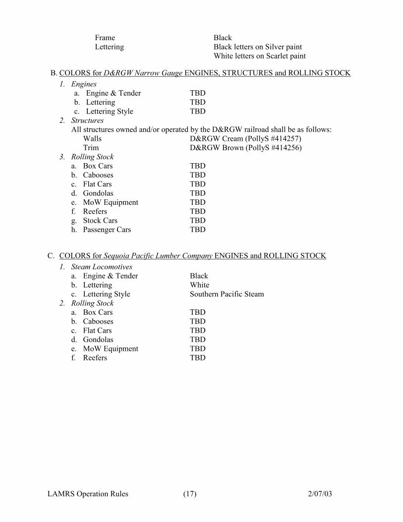
LAMRS Operation Rules (17) 2/07/03
Frame Black
Lettering Black letters on Silver paint
White letters on Scarlet paint
B. COLORS for D&RGW Narrow Gauge ENGINES, STRUCTURES and ROLLING STOCK
1. Engines
a. Engine & Tender TBD
b. Lettering TBD
c. Lettering Style TBD
2. Structures
All structures owned and/or operated by the D&RGW railroad shall be as follows:
Walls D&RGW Cream (PollyS #414257)
Trim D&RGW Brown (PollyS #414256)
3. Rolling Stock
a. Box Cars TBD
b. Cabooses TBD
c. Flat Cars TBD
d. Gondolas TBD
e. MoW Equipment TBD
f. Reefers TBD
g. Stock Cars TBD
h. Passenger Cars TBD
C. COLORS for Sequoia Pacific Lumber Company ENGINES and ROLLING STOCK
1. Steam Locomotives
a. Engine & Tender Black
b. Lettering White
c. Lettering Style Southern Pacific Steam
2. Rolling Stock
a. Box Cars TBD
b. Cabooses TBD
c. Flat Cars TBD
d. Gondolas TBD
e. MoW Equipment TBD
f. Reefers TBD
LAMRS Operation Rules (18) 2/07/03
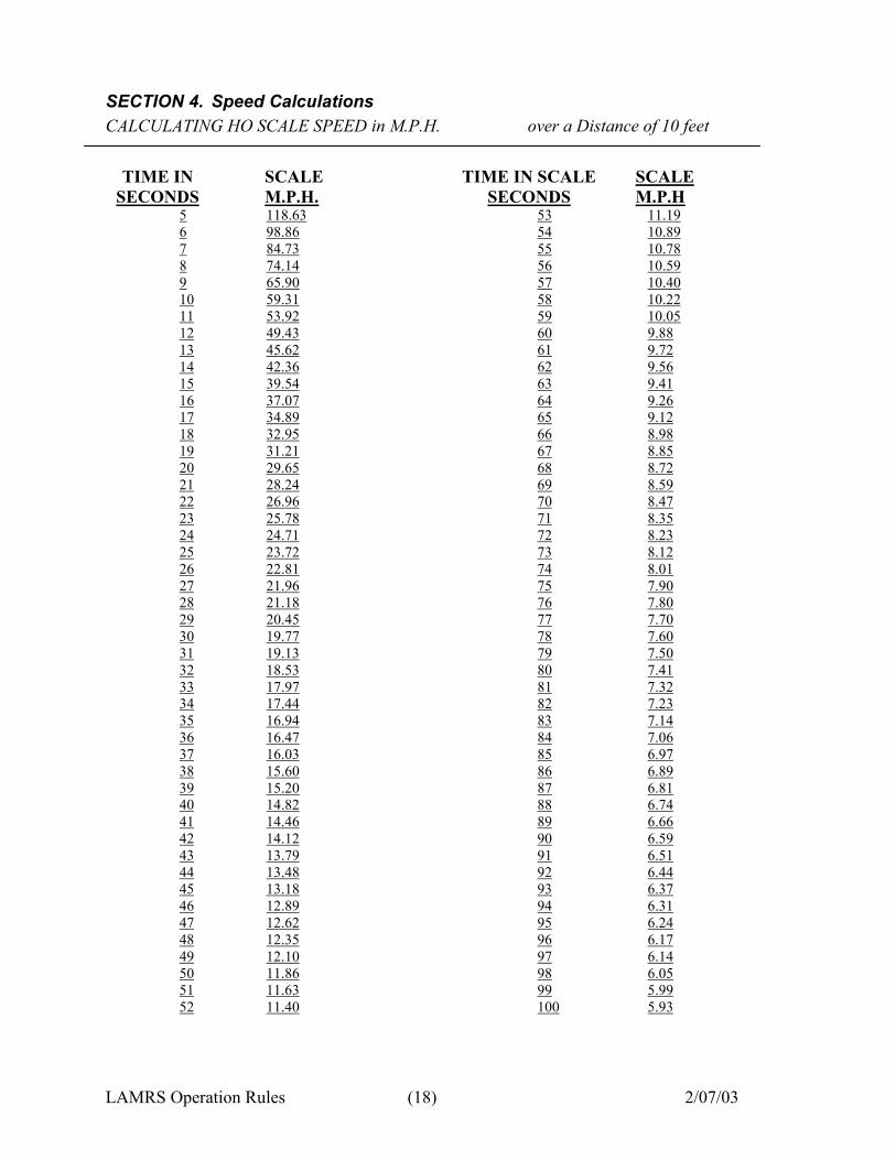
SECTION 4. Speed Calculations
CALCULATING HO SCALE SPEED in M.P.H. over a Distance of 10 feet
TIME IN
SECONDS
SCALE
M.P.H.
TIME IN SCALE
SECONDS
SCALE
M.P.H
5 118.63 53 11.19
6 98.86 54 10.89
7 84.73 55 10.78
8 74.14 56 10.59
9 65.90 57 10.40
10 59.31 58 10.22
11 53.92 59 10.05
12 49.43 60 9.88
13 45.62 61 9.72
14 42.36 62 9.56
15 39.54 63 9.41
16 37.07 64 9.26
17 34.89 65 9.12
18 32.95 66 8.98
19 31.21 67 8.85
20 29.65 68 8.72
21 28.24 69 8.59
22 26.96 70 8.47
23 25.78 71 8.35
24 24.71 72 8.23
25 23.72 73 8.12
26 22.81 74 8.01
27 21.96 75 7.90
28 21.18 76 7.80
29 20.45 77 7.70
30 19.77 78 7.60
31 19.13 79 7.50
32 18.53 80 7.41
33 17.97 81 7.32
34 17.44 82 7.23
35 16.94 83 7.14
36 16.47 84 7.06
37 16.03 85 6.97
38 15.60 86 6.89
39 15.20 87 6.81
40 14.82 88 6.74
41 14.46 89 6.66
42 14.12 90 6.59
43 13.79 91 6.51
44 13.48 92 6.44
45 13.18 93 6.37
46 12.89 94 6.31
47 12.62 95 6.24
48 12.35 96 6.17
49 12.10 97 6.14
50 11.86 98 6.05
51 11.63 99 5.99
52 11.40 100 5.93
LAMRS Operation Rules (19) 2/07/03
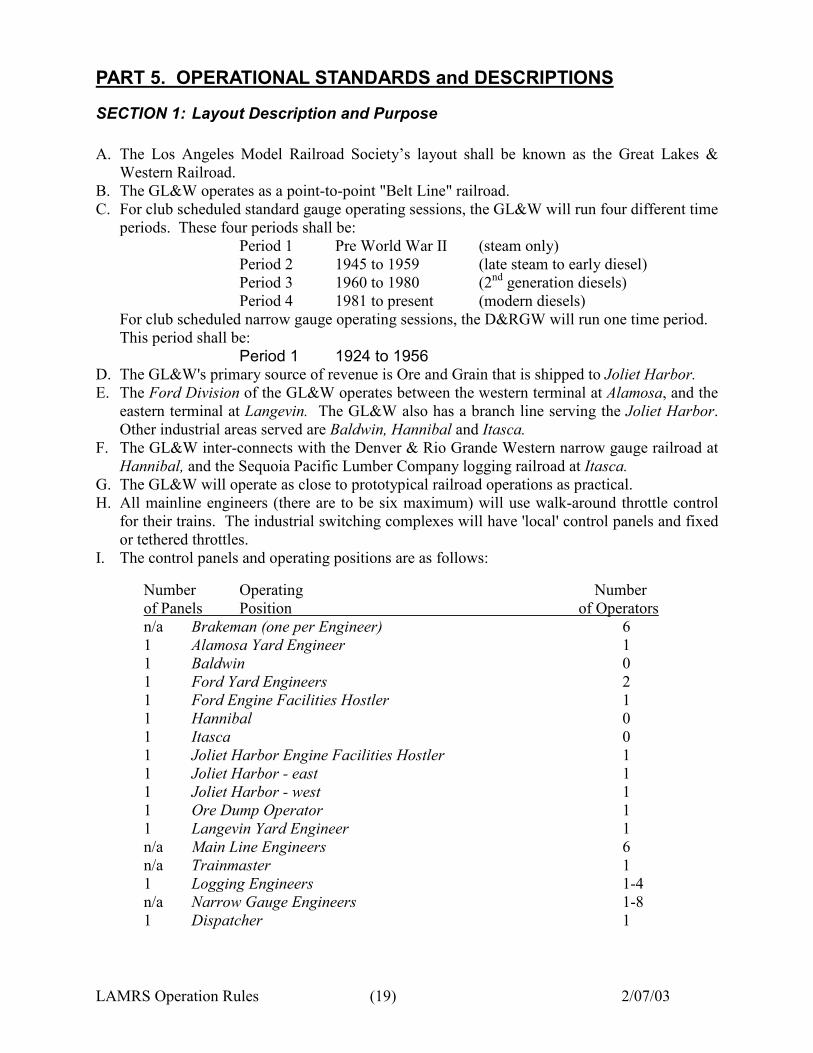
PART 5. OPERATIONAL STANDARDS and DESCRIPTIONS
SECTION 1: Layout Description and Purpose
A. The Los Angeles Model Railroad Society’s layout shall be known as the Great Lakes &
Western Railroad.
B. The GL&W operates as a point-to-point "Belt Line" railroad.
C. For club scheduled standard gauge operating sessions, the GL&W will run four different time
periods. These four periods shall be:
Period 1 Pre World War II (steam only)
Period 2 1945 to 1959 (late steam to early diesel)
Period 3 1960 to 1980 (2nd
generation diesels)
Period 4 1981 to present (modern diesels)
For club scheduled narrow gauge operating sessions, the D&RGW will run one time period.
This period shall be:
Period 1 1924 to 1956
D. The GL&W's primary source of revenue is Ore and Grain that is shipped to Joliet Harbor.
E. The Ford Division of the GL&W operates between the western terminal at Alamosa, and the
eastern terminal at Langevin. The GL&W also has a branch line serving the Joliet Harbor.
Other industrial areas served are Baldwin, Hannibal and Itasca.
F. The GL&W inter-connects with the Denver & Rio Grande Western narrow gauge railroad at
Hannibal, and the Sequoia Pacific Lumber Company logging railroad at Itasca.
G. The GL&W will operate as close to prototypical railroad operations as practical.
H. All mainline engineers (there are to be six maximum) will use walk-around throttle control
for their trains. The industrial switching complexes will have 'local' control panels and fixed
or tethered throttles.
I. The control panels and operating positions are as follows:
Number Operating Number
of Panels Position of Operators
n/a Brakeman (one per Engineer) 6
1 Alamosa Yard Engineer 1
1 Baldwin 0
1 Ford Yard Engineers 2
1 Ford Engine Facilities Hostler 1
1 Hannibal 0
1 Itasca 0
1 Joliet Harbor Engine Facilities Hostler 1
1 Joliet Harbor - east 1
1 Joliet Harbor - west 1
1 Ore Dump Operator 1
1 Langevin Yard Engineer 1
n/a Main Line Engineers 6
n/a Trainmaster 1
1 Logging Engineers 1-4
n/a Narrow Gauge Engineers 1-8
1 Dispatcher 1
LAMRS Operation Rules (20) 2/07/03
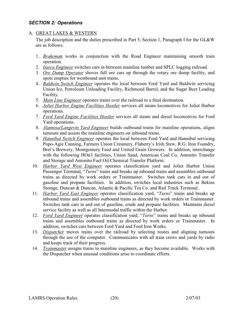
SECTION 2: Operations
A. GREAT LAKES & WESTERN
The job description and the duties prescribed in Part 5, Section 1, Paragraph I for the GL&W
are as follows:
1. Brakeman works in conjunction with the Road Engineer maintaining smooth train
operation.
2. Itasca Engineer switches cars in between mainline lumber and SPLC logging railroad.
3. Ore Dump Operator shoves full ore cars up through the rotary ore dump facility, and
spots empties for westbound unit trains.
4. Baldwin Switch Engineer operates the local between Ford Yard and Baldwin servicing
Union Ice, Petroleum Unloading Facility, Richmond Barrel, and the Sugar Beet Loading
Facility.
5. Main Line Engineer operates trains over the railroad to a final destination.
6. Joliet Harbor Engine Facilities Hostler services all steam locomotives for Joliet Harbor
operations.
7. Ford Yard Engine Facilities Hostler services all steam and diesel locomotives for Ford
Yard operations.
8. Alamosa/Langevin Yard Engineer builds outbound trains for mainline operations, aligns
turnouts and assists the mainline engineers on inbound trains.
9. Hannibal Switch Engineer operates the local between Ford Yard and Hannibal servicing
Popo-Agie Canning, Farmers Union Creamery, Flaherty’s Irish Stew, R.G. Iron Foundry,
Bret’s Brewery, Montgomery Feed and United Grain Growers. In addition, interchange
with the following HOn3 facilities, Union Sand, American Coal Co, Antonito Transfer
and Storage and Antonito Fuel Oil/Chemical Transfer Platform.
10. Harbor Yard West Engineer operates classification yard and Joliet Harbor Union
Passenger Terminal, “Turns” trains and breaks up inbound trains and assembles outbound
trains as directed by work orders or Trainmaster. Switches tank cars in and out of
gasoline and propane facilities. In addition, switches local industries such as Bekins
Storage, Duncan & Duncan, Atlantic & Pacific Tea Co. and Rail Truck Terminal.
11. Harbor Yard East Engineer operates classification yard, “Turns” trains and breaks up
inbound trains and assembles outbound trains as directed by work orders or Trainmaster.
Switches tank cars in and out of gasoline, crude and propane facilities. Maintains diesel
service facility as well as all Intermodal traffic within the Harbor.
12. Ford Yard Engineer operates classification yard, “Turns” trains and breaks up inbound
trains and assembles outbound trains as directed by work orders or Trainmaster. In
addition, switches cars between Ford Yard and Ford Iron Works.
13. Dispatcher moves trains over the railroad by selecting routes and aligning turnouts
through the use of the computer. Communicates with all train crews and yards by radio
and keeps track of their progress.
14. Trainmaster assigns trains to mainline engineers, as they become available. Works with
the Dispatcher when unusual conditions arise to coordinate efforts.
LAMRS Operation Rules (21) 2/07/03
B. SEQUOIA PACIFIC LUMBER COMPANY
The job descriptions and the duties for the SPLC are as follows:
1. Logging Brakeman works in conjunction with the Road Engineer maintaining smooth
train operation.
2. Logging Engineer operates trains over the SPLC railroad as dictated by the master
schedule.
3. DCC Programmer programs locomotive addresses and speed steps, PM4’s and PM42’s.
C. DENVER & RIO GRANDE WESTERN
The job descriptions and the duties for the D&RGW narrow gauge are as follows:
1. Narrow Gauge Brakeman works in conjunction with the Road Engineer maintaining
smooth train operation.
2. Narrow Gauge Engineer operates trains over the HOn3 railroad as dictated by the master
schedule.
3. DCC Programmer programs locomotive addresses and speed steps, PM4’s and PM42’s.
4. Master Scheduler prepares operating schedules utilizing all aspects and industries
incorporated within the D&RGW railroad.
D. TRAINING, TESTING and CERTIFICATION REQUIREMENTS
1. GREAT LAKES & WESTERN
New LAMRS members, desirous of participating in scheduled operating sessions, shall
be required to go through a training and testing period for each of the operating positions
he/she would like to operate. Members shall be "Certified" by the
Membership/Operations Committee, as to their being qualified to operate any position.
The Membership Committee shall notify the Superintendent of Operations of any
members completion of certification.
Testing and Certification criteria for Standard Gauge Operating Positions are as follows:
a. Brakeman -
All new members, or members not qualified in any GL&W position, begin as Train
Conductor/Brakemen. This level introduces the member to geographic locations,
station names, train operations, equipment compatibility, throttle control and radio
protocol. Members will work alongside a Qualified Road Engineer.
b. Ford Yard or Harbor West Yard Locomotive Hostler -
• Must have received instruction on model locomotive compatibility, turnout
control, block and throttle control as well as the functionality of turntable
operation
• Must have a working knowledge of steam and diesel service facilities
c. Road Engineer -
• Must have operated as a Conductor/Brakeman during a minimum of three regular
scheduled operating sessions or have been trained by their mentor and reported
ready for testing
• Must have received instruction on train handling, and general operating rules
• Must observe Train Dispatcher for at least one full operating session
• Must solely operate trains under the supervision of a qualified Locomotive
Engineer for at least one full operating session
d. Yard Engineer -
LAMRS Operation Rules (22) 2/07/03
• Must be a qualified Locomotive Hostler
• Must have received instruction on switchlists and train makeup
• Must be familiar with the operation of all turnouts and toggles
• Must have specific instructions on the operation of each yard panel including the
operation of any "dual-use" features
• Must have operated the yard solely during at least one complete operating session
under the supervision of a qualified Yard Engineer or Yardmaster
e. Yardmaster -
• Must be a qualified Yard and Road Engineer
• Must work as an assistant Yardmaster during one operating session in each of the
three yards, Ford, Harbor and Alamosa/Langevin
f. Train Dispatcher -
• Must be a qualified Road Engineer and Yardmaster
• Must be able to make quick decisions under pressure and maintain smooth train
operation(s)
• Must demonstrate a thorough understanding of the GL&W track and switch
diagram/schematic
• Must work as an Assistant Dispatcher during at least two operating sessions, at
which time topics such as dispatching skills, train priority and radio protocol is
taught by a qualified Train Dispatcher
g. Trainmaster -
• Must be a qualified Train Dispatcher
• Must work as an Assistant Trainmaster during at least two operating sessions
while receiving instruction on the handling of paperwork and assignment of trains
• Must prepare operating schedules to include locomotive numbers, train consists,
arriving and departing times, train orders and switch lists for a complete operating
session based on industry requirements
2. DENVER & RIO GRANDE WESTERN
Every LAMRS member, desirous of participating in scheduled Narrow Gauge operating
sessions, shall be required to go through a training and testing period, for each of the
operating positions he/she would like to operate. Members shall be "Certified" by the
Membership/Operations Committee, as to their being qualified to operate any position.
The Membership Committee shall notify the Superintendent of Operations of any
members completion of certification.
Note: LAMRS members wishing to operate the Narrow Gauge railroad at any
time must be certified as a narrow gauge Brakeman.
Testing and Certification criteria for Narrow Gauge Operating Positions are as follows:
a. Brakeman -
All new members, or members not qualified in any narrow gauge position, begin as
Train Conductors/Brakemen. This level introduces the member to geographic
locations, station names, train operations, equipment compatibility, and radio
protocol. Members will work alongside a Qualified Road Engineer.
• Must learn complete system powering up and down techniques
• Digitrax® throttle control, including how to acquire and dispatch locomotives,
assemble and release multi-unit (MU) lash-ups, and controlling turnouts
LAMRS Operation Rules (23) 2/07/03
• Must have working knowledge of control panels and HO/HOn3 crossing
b. Narrow Gauge Engineer -
• Must have operated as a Conductor/Brakeman during a minimum of three regular
scheduled operating sessions or have been trained by their mentor and reported
ready for testing
• Must have received instruction on train handling, and general operating rules
• Must solely operate trains under the supervision of a qualified Locomotive
Engineer for at least two full operating sessions
c. DCC Programmer -
• Must have received instruction in Locomotive address programming (two and
four digit)
• Must have programming knowledge of Digitrax® throttles including DT100,
DT300 and DT400 models
• Must have working knowledge of speed step tables and CV’s (configuration
variables)
• Must be able to program Digitrax® PM4/PM42’s, DS44 and DS54’s
• Must have a good working knowledge of LocoNet
d. Master Scheduler -
• Must be a qualified Engineer
• Must have knowledge of prototypical operations for the D&RGW including
consisting and train blocking
• Must have a good working knowledge of all industries located within the
D&RGW as well as standard gauge operations within Hannibal
• Establish consignee/shipper requirements for all industries
• Must prepare operating schedules to include locomotive numbers, train consists,
arriving and departing times, train orders and switch lists for a complete operating
session based on industry requirements
E. TRAIN MOVEMENTS
All GL&W train movements shall be under the complete control of, and authorized by, the
GL&W Dispatcher.
F. END OF SESSION
At the end of each scheduled operation session, all rolling stock shall be removed from the
layout and properly stored away.
G. COMMUNICATIONS
During all scheduled operating sessions, the means of communications between the
Dispatcher and all other operators shall be via wireless headsets.
H. SCHEDULE CHANGES
Scheduled changes for operating sessions shall be posted on the club's bulletin board at least
two (2) weeks in advance of the change taking place.
I. OPERATIONS on the NARROW GAUGE or LOGGING RAILROADS
Operations on the narrow gauge or logging railroads are not under the control or jurisdiction
of the GL&W Dispatcher. However, they shall be operated as close to prototypical as
practicable and keeping in line with the rules that governs the GL&W train movements.
LAMRS Operation Rules (24) 2/07/03
J. DONATED ROLLING STOCK and LOCOMOTIVES
All rolling stock and locomotives donated to LAMRS for running on the GL&W shall
become the property of LAMRS and be maintained by its members. All donated cars will be
the usual cars that are slated for switching movements during our "Normal" operating Time
Period of 1945 to Present. With the concurrence of the membership, any donated item not
falling within the GL&W operating time frames shall be sold for profit depositing those
funds in the organizations general operating account.
K. COMPUTER DATABASE
Only those pieces of rolling stock falling within the operating time frame and scenario of the
GL&W shall be inventoried and maintained in the database of the computer.
LAMRS Operation Rules (25) 2/07/03
SECTION 3: Radio Communications
A. DEFINITIONS
1. Call Sign – How you identify who you are (Example: Engineer Red; SP5854 West; Ford
Yardmaster, etc.)
2. Communication dialog – What information you are asking or what information you are
giving. Be brief!
3. “Roger” - Means you understand what was communicated to you and/or you will comply
4. “Out” - Means you are done with this communication dialog
5. “Code Red” - Means you need to interrupt the current dialog for something more
important such as an emergency. All other radio communications should cease.
B. GENERAL RADIO PROTOCOL
1. Wait for radio silence before initiating communications
2. Identify yourself on initial contact using your call sign and wait for a response before
proceeding
3. End communication dialog with your call sign and the word “out” or “roger out” to signal
you are done. “Roger” should be used when you acknowledge a clearance or other
request.
4. If unable to respond to a call, say your call sign and then say “Stand By”.
5. You should only use your throttle color on initial contact with dispatch or the trainmaster.
C. INITIAL CONTACT to DISPATCH by ROAD ENGINEER
1. With Trainmaster Functioning
a. Request: “Dispatch this is Engineer Red”
b. Dispatch: “Go ahead Engineer Red”
c. Road Engineer: “BNSF 5233 West is staged at Harbor East requesting clearance to
Ford Yard”
d. Dispatch: “BNSF 5233 West you are cleared to Itasca, hold in Itasca, report clear of
Joliet Junction”.
e. Road Engineer: “Roger, BNSF 5233 West cleared to Itasca, Out”
2. Without a Trainmaster
a. Request: “Dispatch this is Engineer Red” (Do not contact dispatch until ready to roll)
b. Dispatch: “Go ahead Engineer Red”
c. Road Engineer: “Engineer Red with BNSF 5233West in Harbor East”
d. Dispatch: “Engineer Red, what is your request”?
e. Road Engineer: “BNSF 5233 West requests clearance to Ford Yard”
f. Dispatch: “BNSF 5233 West cleared to Itasca” or the response may be “BNSF 5233
West hold in Harbor East until I contact you again”
g. Road Engineer: “BNSF 5233 roger, out”
h. If the Dispatcher can give immediate clearance the dialog would continue as if
the Trainmaster had been in place
D. DIALOG WHILE UNDER WAY
1. Road engineer maintains radio silence unless called by dispatch or is telling dispatch
what blocks the train has cleared.
a. Example: Road Engineer: “Dispatch, BNSF 5233 West”
LAMRS Operation Rules (26) 2/07/03
b. Dispatch: “BNSF 5233 West this is dispatch go ahead”
c. Road Engineer: “BNSF 5233 West is clear of Harbor Lead and Joliet Junction,
holding in Itasca”
d. Dispatch: “BNSF 5233 West continue to hold in Itasca” or “BNSF 5233 West, you
are cleared to Hunter Siding, hold in Hunter”
e. Road Engineer: “BNSF 5233 roger, out”
E. DIALOG WITH A YARD
1. When a train reaches a block that is the entry point for a yard, the road engineer shall
contact the dispatcher.
a. Example: Road Engineer: “Dispatch, BNSF 5233 West holding in Hunter for Ford
Yard”
b. Dispatch: “BNSF 5233 West, contact Ford Yardmaster on the yard frequency for
entry into Ford Yard, report clear of main line”
c. Road Engineer: “BNSF 5233 West, roger, out”
d. Dispatch: “Dispatch out”
e. Road Engineer: “BNSF 5233 West to the Ford Yardmaster”
f. Ford Yardmaster: “BNSF 5233 West this is Ford Yardmaster”
g. Road Engineer: “BNSF 5233 West request clearance into Ford Yard for a power
switch”
h. Ford Yardmaster: “BNSF 5233 West, what is your throttle color?”
i. Road Engineer: “BNSF 5233 West is Red”
j. Ford Yardmaster: “BNSF 5233 West, you are cleared into Ford Yard, maintain yard
speed”
k. Road Engineer: “BNSF 5233, roger, out”
l. Road Engineer: “Dispatch, BNSF 5233 West
m. Dispatch: “BNSF 5233 West this is dispatch go ahead”
n. Road Engineer: “Dispatch, BNSF 5233 West is clear of the mainline in Ford Yard”
o. Dispatch: “Roger, contact the trainmaster for further assignment, out”
2. Similar transmissions would take place for entrance into staging or other yards.
F. CLEARING BLOCKS
A road engineer must clear each electrical track block that their train has past through by
notifying the dispatcher.
1. Call dispatch when the last car of the train has passed the end of the block.
2. Example: “Dispatch, UP4497 East is clear of Eagle Canyon”.
LAMRS Operation Rules (27) 2/07/03
SECTION 4: Procedure for Facilities Shut Down
A. Exit Dispatcher program and Windows 98 software, turn off computer and cover the monitor
and keyboard.
B. Insure all road throttles are off (switch in down position) and placed in the desk drawer.
C. Shut-off master power switch (switch in down position) located under Joliet Junction.
D. Double check that all power packs are turned off. (Baldwin, Ford Yard, Ford Engine
Facility, Narrow Gauge DCC, Hannibal, Logging DCC, Harbor West Yard, Harbor West
Engine Facility, Harbor East Yard, master switch for Alamosa/Langevin).
E. Check all structure lighting located under Baldwin, Ford, Kramer, Joliet Passenger Terminal,
Harbor East Yard, Bridge and Intermodal Yard, and the Refinery.
F. Shut-off master power switch (switch in down position) for dual use relays under Harbor
East Yard.
G. Check to insure the downstairs door is locked.
H. Close and secure all windows.
I. Shut-off TV, radio and VCR.
J. Shut-off ceiling fans at the breaker box, unplug all other floor fans.
K. Replace the lid on the wheel cleaning (alcohol) station supplies.
L. Listen for anything on or running; (i.e. toilets, fans, etc.)
M. Turn off all overhead interior lights.
N. Close front door, turn cipher lock dead bolt, close and lock the security door with the key.

LAMRS Operation Rules (28) 2/07/03
PART 6. TESTING and CERTIFICATION PROCEDURES

LAMRS Operation Rules (29) 2/07/03
PART 7. APPENDIX