Embed Size (px)
Citation preview
EURONOISE2015/278
Standardized acoustic test fixtures for testing ear protection devices and noise cancelling headsets
Peter Wulf-Andersen
G.R.A.S. Sound & Vibration A/S, Skovlytoften 33, 2840 Holte, Denmark.
Per Rasmussen
G.R.A.S. Sound & Vibration A/S, Skovlytoften 33, 2840 Holte, Denmark.
Abstract
Several acoustic test fixtures can be used for measuring the Insertion Loss of Hearing Protectors
Devices (HPD) and Active Noise Cancelation (ANC) Devices. First, it is very important to have
an Acoustic Test Fixture (ATF) with a very high self-insertion loss to insure that the measured
insertion loss on the Device Under Test (DUT) is not influenced by false signals introduced in the
ATF itself. Secondly, it is important to decide whether a more humanlike shape with a
corresponding Head Related Transfer Function is needed, or a more simplified ATF can be used.
In the first case, the ANSI standard s12.42 describes a proper method, while ISO 4869-3 describes
the second method. The ANSI s12.42 ATF is designed with a special ear canal extension, which is
longer than the standard extension, known from other ATFs like KEMAR, and is fitted with flesh-
like material to better adapt In the Ear (ITE) devices. Thirdly, a large circum-aural pinna is
included to ensure a perfect seal for all kinds of Over The Ear hearing protection devices.
Furthermore, the total system consisting of ear simulator, ear canal extension and pinna are heated
to body temperature. The ISO 4869-3 defines a more simple solution for circum-aural HPD’s, but
can as well as the ANSI standardized ATF bee combined with pinnas, ear canal extensions and ear
simulators for testing ITE devices. The two types of ATF are especially good when testing the
new high quality ANC hearing protectors and headsets, which is why this presentation also looks
at the challenges when measuring on ANC devices.
1. Introduction
1
Hearing protection devices and modern active
noise cancelling headphones are designed to
reduce the background noise from entering the
human ear either to protect the ear from damage or
to decrease the perceived annoyance from the
background noise and to improve the perception of
the sound from the headphone itself in situations
with high background noise.
While the perceived sound quality of the
headphone is a more subjective parameter, the
insertion loss of the headphone is an objective
parameter which can be measured according to
various standards. We will here focus on the
measurements according to ISO 4869-3 (1) and
ANSI S12.42 (2) as established standards. These
standards define Acoustic Test Fixtures (ATF)
with geometry similar to the human head and
include artificial ears as defined in IEC 60318-4.
2. Test setup
The insertion loss of both hearing protection
devices and ANC headphones are measured in a
diffuse sound field. The ATF is placed in the
sound field and the noise level as measured with
the ATF with and without the Device Under Test
(DUT).
The diffuse sound field was established in a large
room (16 x 12 x 6m) with reflecting walls
(Reverberation room) by four loudspeakers
pointing away from the test object. The
loudspeakers were driven by four power amplifiers
and produced an SPL of about 90 dB (1/3 octave)
from 50 Hz to 20 kHz. A comparison of the noise
Copyright© (2015) by EAA-NAG-ABAV, ISSN 2226-5147All rights reserved
1985
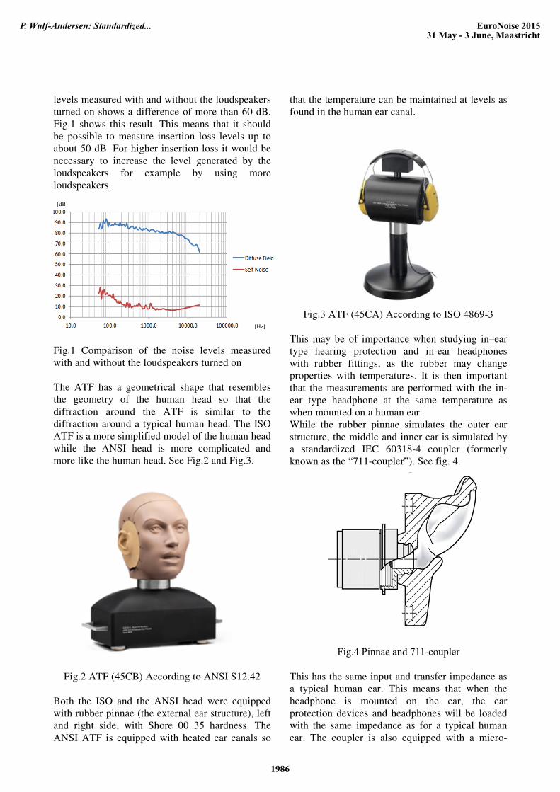
levels measured with and without the loudspeakers
turned on shows a difference of more than 60 dB.
Fig.1 shows this result. This means that it should
be possible to measure insertion loss levels up to
about 50 dB. For higher insertion loss it would be
necessary to increase the level generated by the
loudspeakers for example by using more
loudspeakers.
Fig.1 Comparison of the noise levels measured
with and without the loudspeakers turned on
The ATF has a geometrical shape that resembles
the geometry of the human head so that the
diffraction around the ATF is similar to the
diffraction around a typical human head. The ISO
ATF is a more simplified model of the human head
while the ANSI head is more complicated and
more like the human head. See Fig.2 and Fig.3.
Fig.2 ATF (45CB) According to ANSI S12.42
Both the ISO and the ANSI head were equipped
with rubber pinnae (the external ear structure), left
and right side, with Shore 00 35 hardness. The
ANSI ATF is equipped with heated ear canals so
that the temperature can be maintained at levels as
found in the human ear canal.
Fig.3 ATF (45CA) According to ISO 4869-3
This may be of importance when studying in–ear
type hearing protection and in-ear headphones
with rubber fittings, as the rubber may change
properties with temperatures. It is then important
that the measurements are performed with the in-
ear type headphone at the same temperature as
when mounted on a human ear.
While the rubber pinnae simulates the outer ear
structure, the middle and inner ear is simulated by
a standardized IEC 60318-4 coupler (formerly
known as the “711-coupler”). See fig. 4.
Fig.4 Pinnae and 711-coupler
This has the same input and transfer impedance as
a typical human ear. This means that when the
headphone is mounted on the ear, the ear
protection devices and headphones will be loaded
with the same impedance as for a typical human
ear. The coupler is also equipped with a micro-
[Hz]
[dB]
EuroNoise 201531 May - 3 June, Maastricht
P. Wulf-Andersen: Standardized...
1986
phone, in a position where the human eardrum
would normally be. This means that the
microphone will record the sound pressure as it
would be at a typical ear drum of a typical listener.
The signals from the left side and right side
microphones was recorded and analyzed with a
Dynamic Signal Analyzer.
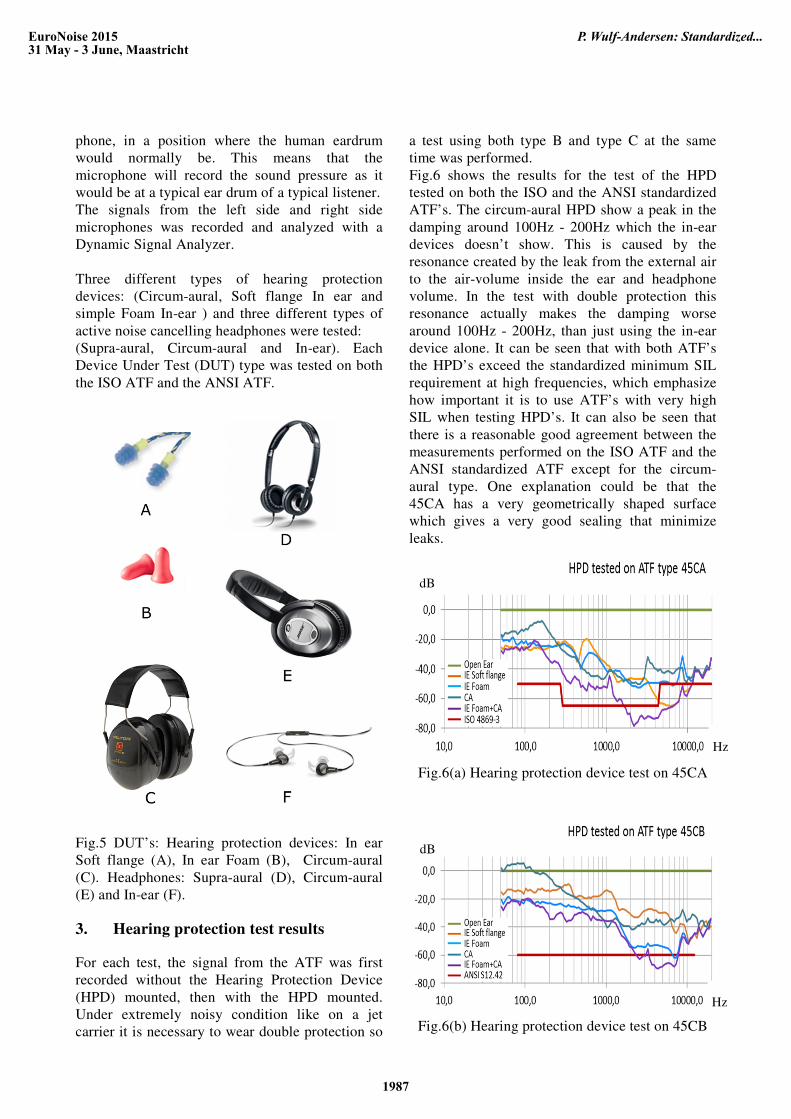
Three different types of hearing protection
devices: (Circum-aural, Soft flange In ear and
simple Foam In-ear ) and three different types of
active noise cancelling headphones were tested:
(Supra-aural, Circum-aural and In-ear). Each
Device Under Test (DUT) type was tested on both
the ISO ATF and the ANSI ATF.
Fig.5 DUT’s: Hearing protection devices: In ear
Soft flange (A), In ear Foam (B), Circum-aural
(C). Headphones: Supra-aural (D), Circum-aural
(E) and In-ear (F).
3. Hearing protection test results
For each test, the signal from the ATF was first
recorded without the Hearing Protection Device
(HPD) mounted, then with the HPD mounted.
Under extremely noisy condition like on a jet
carrier it is necessary to wear double protection so
a test using both type B and type C at the same
time was performed.
Fig.6 shows the results for the test of the HPD
tested on both the ISO and the ANSI standardized
ATF’s. The circum-aural HPD show a peak in the
damping around 100Hz - 200Hz which the in-ear
devices doesn’t show. This is caused by the
resonance created by the leak from the external air
to the air-volume inside the ear and headphone
volume. In the test with double protection this
resonance actually makes the damping worse
around 100Hz - 200Hz, than just using the in-ear
device alone. It can be seen that with both ATF’s
the HPD’s exceed the standardized minimum SIL
requirement at high frequencies, which emphasize
how important it is to use ATF’s with very high
SIL when testing HPD’s. It can also be seen that
there is a reasonable good agreement between the
measurements performed on the ISO ATF and the
ANSI standardized ATF except for the circum-
aural type. One explanation could be that the
45CA has a very geometrically shaped surface
which gives a very good sealing that minimize
leaks.
Fig.6(a) Hearing protection device test on 45CA
Fig.6(b) Hearing protection device test on 45CB
dB
Hz
Hz
dB
EuroNoise 201531 May - 3 June, Maastricht
P. Wulf-Andersen: Standardized...
1987
4. Headphone test results
For each test, the signal from the ATF was first
recorded without the headphone mounted, then
with the headphone mounted with the active noise
cancelling function turned off (Passive mode) and
then with the active noise cancelling function
turned on (Active mode).
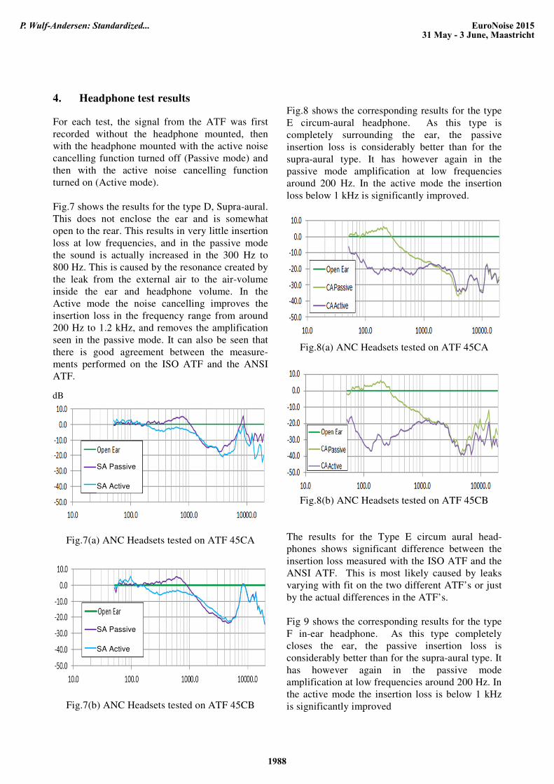
Fig.7 shows the results for the type D, Supra-aural.
This does not enclose the ear and is somewhat
open to the rear. This results in very little insertion
loss at low frequencies, and in the passive mode
the sound is actually increased in the 300 Hz to
800 Hz. This is caused by the resonance created by
the leak from the external air to the air-volume
inside the ear and headphone volume. In the
Active mode the noise cancelling improves the
insertion loss in the frequency range from around
200 Hz to 1.2 kHz, and removes the amplification
seen in the passive mode. It can also be seen that
there is good agreement between the measure-
ments performed on the ISO ATF and the ANSI
ATF.
Fig.7(a) ANC Headsets tested on ATF 45CA
Fig.7(b) ANC Headsets tested on ATF 45CB
Fig.8 shows the corresponding results for the type
E circum-aural headphone. As this type is
completely surrounding the ear, the passive
insertion loss is considerably better than for the
supra-aural type. It has however again in the
passive mode amplification at low frequencies
around 200 Hz. In the active mode the insertion
loss below 1 kHz is significantly improved.
Fig.8(a) ANC Headsets tested on ATF 45CA
Fig.8(b) ANC Headsets tested on ATF 45CB
The results for the Type E circum aural head-
phones shows significant difference between the
insertion loss measured with the ISO ATF and the
ANSI ATF. This is most likely caused by leaks
varying with fit on the two different ATF’s or just
by the actual differences in the ATF’s.
Fig 9 shows the corresponding results for the type
F in-ear headphone. As this type completely
closes the ear, the passive insertion loss is
considerably better than for the supra-aural type. It
has however again in the passive mode
amplification at low frequencies around 200 Hz. In
the active mode the insertion loss is below 1 kHz
is significantly improved
dB
SA Passive
SA Active
SA Passive
SA Active
EuroNoise 201531 May - 3 June, Maastricht
P. Wulf-Andersen: Standardized...
1988
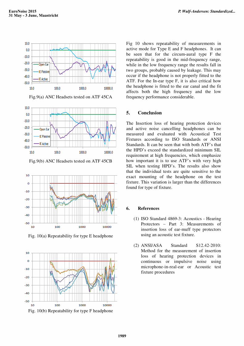
Fig.9(a) ANC Headsets tested on ATF 45CA
Fig.9(b) ANC Headsets tested on ATF 45CB
Fig. 10(a) Repeatability for type E headphone
Fig. 10(b) Repeatability for type F headphone
Fig 10 shows repeatability of measurements in
active mode for Type E and F headphones. It can
be seen that for the circum-aural type F the
repeatability is good in the mid-frequency range,
while in the low frequency range the results fall in
two groups, probably caused by leakage. This may
occur if the headphone is not properly fitted to the
ATF. For the In-ear type F, it is also critical how
the headphone is fitted to the ear canal and the fit
affects both the high frequency and the low
frequency performance considerable.
5. Conclusion
The Insertion loss of hearing protection devices
and active noise cancelling headphones can be
measured and evaluated with Acoustical Test
Fixtures according to ISO Standards or ANSI
Standards. It can be seen that with both ATF’s that
the HPD’s exceed the standardized minimum SIL
requirement at high frequencies, which emphasize
how important it is to use ATF’s with very high
SIL when testing HPD’s. The results also show
that the individual tests are quite sensitive to the
exact mounting of the headphone on the test
fixture. This variation is larger than the differences
found for type of fixture.
6. References
(1) ISO Standard 4869-3: Acoustics - Hearing
Protectors – Part 3: Measurements of
insertion loss of ear-muff type protectors
using an acoustic test fixture.
(2) ANSI/ASA Standard S12.42-2010:
Method for the measurement of insertion
loss of hearing protection devices in
continuous or impulsive noise using
microphone-in-real-ear or Acoustic test
fixture procedures
EuroNoise 201531 May - 3 June, Maastricht
P. Wulf-Andersen: Standardized...
1989

EuroNoise 201531 May - 3 June, Maastricht
P. Wulf-Andersen: Standardized...
1990