Embed Size (px)
Citation preview
STANDARDIZATION OF ACOUSTIC EMISSION TESTING OF FOSSIL POWER PLANT SEAM-WELDED HIGH ENERGY PIPING
John M. Rodgers
Acoustic Emission Consulting, Inc.
Richard M. Tilley Electric Power Research Institute
ABSTRACT The structural integrity of seamed fossil high energy
piping has become a major safety and O&M issue again
with eight recent failures of seam-welded piping since
1992. These include failure of six superheat link piping
segments, two of them catastrophic, and the failures of two
long-seamed bends in hot reheat lines. Advanced methods
of inspecting piping welds with ultrasonic techniques, such
as Time Of Flight Diffraction and Focused/Phased Arrays,
is pushing back the envelop of detection to earlier stages of
creep damage. But these are still very expensive and
involve considerable logistics planning and downtime to
perform. EPRI has sponsored development activities since
1986 to mature the utilization of a real-time online
evaluation method for seam-welded piping: Acoustic
Emission (AE) Guidelines were published in 1995, and
over 90 full-scale tests have been performed from 1996-
2003 to develop a database and correlate results with other
established evaluation methods.
Tests to date have shown high sensitivity to early
stage creep damage, which is evidenced by development of
cavities (cavitation) around nonmetallic inclusions and
carbides in the grain boundaries of the weld heat affected
zone and fusion zone. Successful double-blind testing with
advanced ultrasonsic inspection methods, and additional
confirmation with advanced cryo-cracking metallography,
have proven both the reliability and sensitivity of the AE
technique. The economics of the method are highly
favorable. Only small areas of insulation need to be
removed every 4.6-6.1 m (15-20 ft) to weld “waveguides”
to the piping surface. These form a linear location array
along the length of piping, providing global coverage of the
piping system. Testing is performed online with normal
peak loading and load cycling. No outage schedule is
required to perform the AE examination. The ASTM
E07.04 Subcommittee on Acoustic Emission is currently
developing a standard based on the EPRI testing database:
Document WK658, “Standard Test Method for Acoustic
Emission Examination of Seam-Welded High Energy
Piping.” Results will be presented showing that the AE
method has become a reliable and economical field
evaluation tool for seamed high energy piping.
Seam-Welded Piping Issues Ever since the catastrophic failures of seam-welded,
hot reheat (HRH) piping at Southern California Edison’s
Mohave plant in 1985, and Detroit Edison’s Monroe plant
in 1986, utility companies have been carefully considering
the need for periodic inspections of critical piping to guard
against creep-induced failures. Figure 1 illustrates the
creep damage mechanisms associated with seam-welded,
high energy piping. A number of serious defects in seamed
piping were removed after inspections in the late 1980’s,
and for a number of years there were no more catastrophic
failures (Foulds et al, 1996).
Beginning in 1992, however, there have been six
known failures of seam-welded superheat (SH) link piping
supplied with CE boilers, as well as two failures in hot
reheat long seamed bends. Two of these have been
catastrophic: Virginia Power’s Mt. Storm Unit 1 in June
1996, and Kansas City Power & Light’s Hawthorne Unit 5
in August 1998 (Figure 2). No loss of life occurred in
either of those two failures, but the cost of repairs and loss
of power generation is of critical concern to utility
companies in this age of growing competition. All failures
of SH link piping have occurred on units with accumulated
service time of 125,000 to 225,000 hrs. Compounding the
problem of inspection is the inaccuracy of supplied
documentation, which may not reflect the true alloy
To be presented at the ASME Pressure Vessel & Piping Conference, San Diego, July 2004 1 of 19

content and method of fabrication. The Hawthorne SH link
piping was not known to be seam-welded. The general
aging of fossil plants will continue to raise concerns about
the safety of operating seamed high energy piping systems.
Even seamless piping systems have had problems,
including creep-related failures of circumferential welds,
and the through-wall creep failure of a seamless SH bend
that had been improperly fabricated. Current strategies for
effectively managing the safety and life of seam-welded
piping are based upon periodic inspection of the weld area
for evidence of inservice damage.
Inspection Issues The normal inspection process is arduous: wait for a
scheduled outage, remove insulation from large areas of
piping, and conduct ultrasonic (UT) inspections of every
inch of seam weld. The documentation issue creates
additional uncertainty about what and where to inspect.
Often the utility must resort to acid etching sections of
piping to identify the seam weld condition and its location
on the pipe, especially if the piping has been finish
machined after fabrication. Certain areas, such as welds
under hanger attachments and at floor penetrations, are not
typically inspected due to the additional costs of access. In
some cases, the inspections have not produced reliable
results. The through-wall failure in a Sabine HRH elbow in
1992 was preceded by UT inspections five and three years
before failure. The Mt. Storm SH link piping failure in
1996 was preceded by UT inspection 14 months prior to
failure. The failure of a long seamed HRH bend at Gaston
in 2001 raised additional concern about projecting the
results of inspection from other line segments. The same
bend on the mirror image HRH line of the two-line system
had been inspected with Time of Flight Diffraction (TOFD)
UT five years earlier, but had not indicated any problems.
The lack of a predictable re-inspection interval to avoid
this type of failure has become problematic on top of the
high inspection costs and plant downtime. In addition
many utilities are going to extended outage schedules,
limiting the time and interval available for periodic off-line
inspections.
More automated UT techniques using TOFD and
Focused Array Transducer System (FATS) have come to
fore in the past two years as reliable methods of pushing
back the envelope of detection of creep-induced defect
conditions; but these are even more expensive to apply as
general survey methods than conventional multi-angle,
pulse-echo UT inspections. Conventional stress and
materials analysis methods are only marginally useful in
predicting location and timing of the development of creep
damage. Changing conditions on the line with time may
alter the effectiveness of hangers, and general relaxation
effects change stresses from the original installed
condition. Peaked weld geometries, welding materials,
methods and post-weld heat treatment add an additional
range of variables to the prediction of when and where. A
physical test that could inexpensively locate areas of
potential damage---while the unit is in operation--- would
offer the best safety and cost solution to the problem of
seam-welded piping management. That technology is
acoustic emission monitoring, and the results to date are
very encouraging.
Acoustic Emission Monitoring Acoustic emission (AE) has been used
extensively in the past thirty years in the petrochemical,
nuclear, and aerospace industries, and has been
incorporated into a variety of society inspection codes and
practices (ASME, ASTM, ASNT). Aerial manlift vehicles
on the transmission and distribution side of electric utility
companies have been routinely inspected with AE since the
early 1980’s (ASTM F914-85). Acoustic emission is an
attractive alternative to conventional inspection. Its
principal features as applied to high energy piping are:
1. It is a passive monitoring technique, which listens for
the high frequency sounds of material failures and defect
growth. The detected energy comes from sound waves
generated by growing flaws, and developing metallurgical
damage mechanisms (eg. yielding, inclusion decohesion,
deformation twinning, etc)
2. Emission sources can be “source-located” within a
few inches on linear lengths of piping by time-of-arrival
techniques, similar to seismology.
3. It is a global inspection. Any defect growing in the
metal path can be detected and located. This includes
seam, closure, and hanger welds, drains, vents, etc.
To be presented at the ASME Pressure Vessel & Piping Conference, San Diego, July 2004 2 of 19
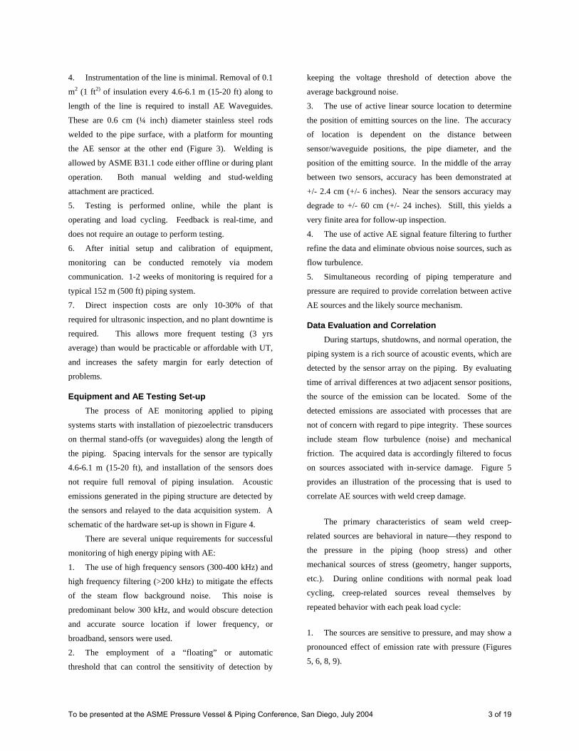
4. Instrumentation of the line is minimal. Removal of 0.1
m2 (1 ft2) of insulation every 4.6-6.1 m (15-20 ft) along to
length of the line is required to install AE Waveguides.
These are 0.6 cm (¼ inch) diameter stainless steel rods
welded to the pipe surface, with a platform for mounting
the AE sensor at the other end (Figure 3). Welding is
allowed by ASME B31.1 code either offline or during plant
operation. Both manual welding and stud-welding
attachment are practiced.
5. Testing is performed online, while the plant is
operating and load cycling. Feedback is real-time, and
does not require an outage to perform testing.
6. After initial setup and calibration of equipment,
monitoring can be conducted remotely via modem
communication. 1-2 weeks of monitoring is required for a
typical 152 m (500 ft) piping system.
7. Direct inspection costs are only 10-30% of that
required for ultrasonic inspection, and no plant downtime is
required. This allows more frequent testing (3 yrs
average) than would be practicable or affordable with UT,
and increases the safety margin for early detection of
problems.
Equipment and AE Testing Set-up The process of AE monitoring applied to piping
systems starts with installation of piezoelectric transducers
on thermal stand-offs (or waveguides) along the length of
the piping. Spacing intervals for the sensor are typically
4.6-6.1 m (15-20 ft), and installation of the sensors does
not require full removal of piping insulation. Acoustic
emissions generated in the piping structure are detected by
the sensors and relayed to the data acquisition system. A
schematic of the hardware set-up is shown in Figure 4.
There are several unique requirements for successful
monitoring of high energy piping with AE:
1. The use of high frequency sensors (300-400 kHz) and
high frequency filtering (>200 kHz) to mitigate the effects
of the steam flow background noise. This noise is
predominant below 300 kHz, and would obscure detection
and accurate source location if lower frequency, or
broadband, sensors were used.
2. The employment of a “floating” or automatic
threshold that can control the sensitivity of detection by
keeping the voltage threshold of detection above the
average background noise.
3. The use of active linear source location to determine
the position of emitting sources on the line. The accuracy
of location is dependent on the distance between
sensor/waveguide positions, the pipe diameter, and the
position of the emitting source. In the middle of the array
between two sensors, accuracy has been demonstrated at
+/- 2.4 cm (+/- 6 inches). Near the sensors accuracy may
degrade to +/- 60 cm (+/- 24 inches). Still, this yields a
very finite area for follow-up inspection.
4. The use of active AE signal feature filtering to further
refine the data and eliminate obvious noise sources, such as
flow turbulence.
5. Simultaneous recording of piping temperature and
pressure are required to provide correlation between active
AE sources and the likely source mechanism. Data Evaluation and Correlation
During startups, shutdowns, and normal operation, the
piping system is a rich source of acoustic events, which are
detected by the sensor array on the piping. By evaluating
time of arrival differences at two adjacent sensor positions,
the source of the emission can be located. Some of the
detected emissions are associated with processes that are
not of concern with regard to pipe integrity. These sources
include steam flow turbulence (noise) and mechanical
friction. The acquired data is accordingly filtered to focus
on sources associated with in-service damage. Figure 5
provides an illustration of the processing that is used to
correlate AE sources with weld creep damage.
The primary characteristics of seam weld creep-
related sources are behavioral in nature—they respond to
the pressure in the piping (hoop stress) and other
mechanical sources of stress (geometry, hanger supports,
etc.). During online conditions with normal peak load
cycling, creep-related sources reveal themselves by
repeated behavior with each peak load cycle:
1. The sources are sensitive to pressure, and may show a
pronounced effect of emission rate with pressure (Figures
5, 6, 8, 9).
To be presented at the ASME Pressure Vessel & Piping Conference, San Diego, July 2004 3 of 19

2. During load cycling, emission rates will typically peak
near the start of the peak load period.
3. There is periodic emission activity during steady-state
pressure and temperature conditions.
4. The AE location profile is typically spread out over 1
meter (40 inches) or more of piping length, and shows
intermittent high-density locations of activity (Figure 5).
5. The amplitude range of emission sources broadens to
higher values with higher activity rates (Figure 5).
6. Emission rates are much higher during startup
conditions, even before substantial pressure loading. This
demonstrates that the damaged area is responsive to
stresses even when the piping is not in the creep regime
(>510 C , 950 F).
The amount of emission generated by the creep
mechanism, the repetitive nature with each peak load cycle,
and the extensive dynamic range (45-90 dB amplitude) of
signals, is extraordinarily different from normal ductile
fracture mechanisms--- such as fatigue crack growth in
mild steels. Many thousands of locatable signals are
sometimes accumulated over several feet of weld length
and several cycles (days) of steam line operation at peak
load. The sheer numbers of the sources is inconsistent with
a ductile crack growth mechanism, which produces
infrequent emission of more limited dynamic range with
repeated load cycles. The acknowledged mechanism of
creep in seam welds is the development of cavities
(cavitation) around nonmetallic inclusions and carbides on
the grain boundaries in the fine-grained heat affected zone
(HAZ) or fusion zone of the seam weld (Figure 1). Isolated
cavities soon give way to aligned cavitation along grain
boundaries, then coalescing into scattered microcracking.
Final consolidation and linking into macrocracking along
the seam weld direction occurs in the last stage of growth,
which can be very rapid depending on a host of factors
(wall thickness, annealing state, inclusion densities,
thermal and localized mechanical stresses, etc).
The early stage of this process involves the degradation
of the bonding between particles and the metal matrix.
These are load-carrying interfaces, and their eventual
failure (decohesion) is the most plausible explanation for
the amount and dynamic range of emission detected in the
creep process. From the viewpoint of classifying AE
behavior, this bears similarity to the experience of
monitoring an organic-based composite material that has
incurred extensive matrix damage. This also explains the
emission that has been noted during the thermal excursion
on startups, even without pressure in the system, when the
piping is clearly not operating in the creep range.
Damaged particle-to-matrix interfaces are prone to
disbonding under high strain conditions, and startups are
known to produce an even higher axial strain than at full
load operation. Indeed the results of the extensive EPRI
field testing program to date has yielded detection of
cavitation damaged seam welds that have not developed to
the stage of micro- or macro-cracking.
Lest this raise the concern that cracking would not be
detected were it occurring, a separate test program
conducted in collaboration with a UK utility demonstrated
that creep crack growth in small specimens produced ever
increasing emission with increased crack growth rate.
Again the emission rate was orders of magnitude higher for
the increment of crack growth than would have been
expected at lower temperatures and growth under fatigue
conditions. The decohesion mechanism remains active
throughout the creep regime, regardless of whether induced
by directed stress at the tip of an active crack or in a
volume of weld without visible cracking. This leads to
certain detection of the creep-related failure process from
very early stages, approximated at 50% of remaining life.
Field Testing Program In 1986 EPRI began investigating AE testing to
quickly screen large areas of piping while the plant is
operating, then come back later for a closer look with
conventional UT examination methods. Beginning in 1991
with a joint R&D program with Pacific Gas & Electric,
EPRI charted the course for the development of a reliable
field procedure. That program produced the EPRI
Acoustic Emission Monitoring Guidelines (Morgan and
Foster, 1995), a comprehensive guide to seam-welded
HRH line inspection. It was demonstrated in double-blind
testing in 1994 on PG&E’s Potrero Unit 3 HRH line, where
the results from AE testing and conventional UT were
successfully corroborated.
To be presented at the ASME Pressure Vessel & Piping Conference, San Diego, July 2004 4 of 19

Over the period of 1995-2000 an extensive field
testing program was undertaken to build a database of
results performed to the EPRI Guidelines criteria. These
were used to verify the methodology, refine evaluation
criteria, and compare the results with other
inspection/evaluation methods. Thirty inspection programs
were conducted on both HRH and SH seam-welded piping
systems for twelve different utility companies. Table 1
provides a summary of the more significant findings, and
follow-on results to date. Some of these have included
Tailored Collaboration projects between EPRI and its
member utilities, including Central & Southwest (Central
Power & Light and West Texas Utilities, now a division of
American Electric Power), American Electric Power,
Kentucky Utilities (now LGE Energy), Illinois Power (now
Dynegy), United Illuminating (now part of PSE&G
Energy), Southwestern Public Service Co (Xcel Energy)
and Sierra Pacific Power. Other companies have started
their own inspection programs, including Sunflower
Electric, Oklahoma Gas & Electric, Grand River Dam
Authority, Northern Indiana Public Service Co, PECO
Energy (Exelon), Minnkota Power, and Entergy.
A typical inspection of 1502 m (500 ft) of HRH
piping with UT will often require extensive scaffolding,
complete insulation removal and reapplication, and 2-3
weeks of plant downtime. This can easily run into the
$300K range for this length of piping. Often time is spent
evaluating material conditions that do not represent active
defect sources (original welding flaws, plate laminations,
e.g.). An AE test program will typically cost <$60K for
the same coverage. AE only detects active (developing)
flaw sites, and therefore focuses the priorities for follow-on
inspection. This can lead to findings that would otherwise
be ignored or not pursued aggressively enough. Several
examples of this occurred during AE testing programs.
In the original proof-of-method AE test on PG&E’s
Potrero Unit 3 HRH line, several defect conditions were
found that would otherwise not have been noted without
the AE testing. These included a cracked saddle weld in a
hanger support, cracks in a cast elbow, and ID-connected
thermal fatigue cracking in the parent material adjacent to a
spool closure weld. None of these defects was a serious
structural threat, but the sensitivity of the AE technique
was established. The following sections summarize some
specific results from the field testing program.
Central Power & Light Joslin Unit 1 HRH An early AE test using the EPRI guideline approach
was the inspection of Central Power & Light’s Joslin Unit
1 HRH line in April 1997. A series of AE sources was
being source-located at a mechanical hanger location on
the bottom of the line (Figure 6). This position showed
unusual behavior for a hanger location—AE was observed
to be sensitive to the pressure gradient, and continued
under steady-state high load conditions. In a normal
inspection scenario, the hanger would not have been
removed. During the following outage, the hanger strap
was removed and the indications verified in the seam weld
by both manual and automated (multi-angle pulse echo and
TOFD) UT inspection. A 25 cm (10 inch) square plate
section was removed from the line and the suspected seam
weld location investigated with both conventional
metallography at 500X, and with more sensitive
“cryocracking” and SEM examination at 5000X (Figures
7a, 7b). A reliable method of early creep detection is a
method known as cryocracking. It is capable of identifying
the condition when damage still exists as isolated
cavitation around carbides and inclusions in the weld HAZ.
The specimen is scored at the desired analysis location,
submerged in liquid nitrogen to supercool the material, and
then impacted to break the material along the preferred
plane. Careful examination under SEM magnifications of
up to 5000X is required to observe the fine structural detail
of the fracture surface. The conventional metallographic
preparation showed no cavitation or cracking to verify the
UT indications. The SEM examination showed that creep
cavitation was present in the lower weld bead. This early
test demonstrated that the online testing methodology with
AE was both very sensitive to early stage creep damage,
and that it could also be verified with the proper UT
inspection methods and a more sensitive metallographic
technique. Using AE monitoring to direct the follow-up
inspection averted a potentially serious future problem, one
that would not likely have been discovered with
conventional inspection approaches.
To be presented at the ASME Pressure Vessel & Piping Conference, San Diego, July 2004 5 of 19

American Electric Power Tests Two tests were conducted on AEP’s Gavin Units 1 &
2. Gavin Unit 1 was the subject of another double blind
test with UT inspection in the summer of 1996. The lower
152 m (500 ft) of the dual-line, 366 m (1200 ft) HRH
piping system was inspected first with both manual and
TOFD UT during a planned outage. This was followed by
online AE testing for several weeks during peak load
cycling operation. AE detected two areas of activity on
elbow closure welds, and two minor areas of activity on
turbine leads. The closure weld indications correlated with
OD-connected shallow cracks that had been visually
ground out during the outage. The two areas on the turbine
leads also matched UT indications. The pattern of
intermittent indications, and length of line affected,
matched up well between the UT and AE methods. None
of these indications was an immediate structural problem.
A spool piece with a high density of plate laminations in
another turbine lead was flagged as a potential problem by
AEP. But the AE results showed nothing of significance
going on in this structure, and future costs for re-inspecting
this area with UT on a regular basis can be averted.
Testing of the full 366 m (1200 ft) of Gavin Unit 2 in 1997
revealed no significant AE indications anywhere on the
line. The estimated cost savings on this line by using AE
screening in place of conventional UT inspection was
$500K, not counting potential lost power generation.
Kentucky Utilities Tests Two significant inspection programs were conducted
at Kentucky Utilities Ghent Unit 1 and Brown Unit 3 in
1997. Several exit elbows in the HRH link piping at Ghent
were found to have highly active AE sources during startup
and subsequent online AE monitoring (Figure 8). Manual
UT inspection confirmed all five indicated areas of
activity. Weld repairs were conducted to remove most of
the indicated weld material. AE Monitoring was
performed after weld repair. The two elbows that had been
repaired by through-wall removal of weld metal showed a
90% reduction in AE activity to very low levels. The SH
link piping was also monitored on this unit, and showed no
significant activity. Such was not the case at Brown Unit
3.
The seam-welded SH link piping leads (3.7 m [12 ft]
vertical segments) were monitored at KU’s Brown Unit 3
during a unit restart following the Spring outage in 1997.
Both leads were observed to have active AE sources in
areas below the penthouse roof. These areas were similar
to the location of a through-wall failure on a SH link at
Alabama Power’s Gaston plant in 1992. Monitoring was
performed during online operation again in Feb. 1998,
prior to an outage when the links were scheduled for
replacement. Similar AE activity was observed in the
suspect areas (Figure 9). The West lead was removed and
sent to the EPRI NDE Center in Charlotte, NC for further
analysis. A phased-array automated UT inspection was
performed on the seam weld, and significant indications
were observed in a 60 cm (24 inch) long area matching the
AE source location results. A 1.2 cm (3 inch) plug sample
was taken for metallographic analysis. No cracking or
cavitation was evident with normal metallographic
preparation and examination at 500X, so the specimen was
sent to Materials & Mechanical Engineering in Austin, TX
for further analysis. The cryocracking examination
identified evidence of early-stage creep cavitation in the
weld centerline (Figure 10). These sophisticated UT and
metallographic methods confirmed that AE had identified a
developing problem well ahead of the appearance of
microcracking, which later would coalesce into a major
crack. This added perhaps years to the early detection of
the problem, and allowed the utility to remove a future
hazard on a reasonably planned schedule.
Illinois Power Tests Another recent AE monitoring program at Illinois
Power’s Baldwin and Wood River plants identified
potential creep problems in several seam-welded elbows
and bends. Structural Integrity Associates (Silver Spring,
MD) was contracted to perform TOFD and FATS UT
inspection on one of the clamshell elbows on Baldwin Unit
1. They found evidence of early-stage creep cavitation in
the midspan extrados weld of the elbow, in the location the
AE results had predicted (Figure 11). This result matched
well with the expectations of the AE monitoring, which
identified this area as a low-activity source. The utility
now knows where the bellwether indicators are on the line,
To be presented at the ASME Pressure Vessel & Piping Conference, San Diego, July 2004 6 of 19
References and the approximate level of damage it represents.
Periodic future inspections or metallographic examination
can be used to plan a replacement or repair schedule
consistent with the company’s operating objectives.
Foulds, J. R., Viswanathan, R., Landrum, J.L., 1996,
“Guidelines for the Evaluation of Seam-Welded High
Energy Piping,”Electric Power Research Institute, . TR-
104631.
Morgan, B.C., Foster, C. L., 1995, “Acoustic Emission
Monitoring of High-Energy Piping, Volume 1: Acoustic
Emission Monitoring Guidelines for Hot Reheat Piping,”
Electric Power Research Institute,. TR-105265-V1.
Conclusions
Acoustic emission has proven its worth in these and
other test programs. Approximately 30% of lines tested
have shown no significant findings, and most others have
shown only minor activity at suspect locations. The
majority of seam weld findings have been in elbows and
bends, followed by hanger locations on horizontal line
segments. These are known to be higher stressed areas,
and offer further validation of the AE methodology. The
correlation with follow-on nondestructive inspection has
been very good, but the lesser sensitivity of UT inspection
methods will generally not confirm early stage creep
damage at the isolated cavitation stage. The economics of
inspection and relative certainty of detection at an early
stage of creep damage should be increasingly attractive to
companies attempting to manage their piping systems in a
climate of reduced capital and O&M spending.
Munson, R., Rodgers, J., Tilley, R., 1999, “The
Utilization of Advanced Metallographic Techniques to
Verify In-service Damage in Long-seam Welded, High
Energy Piping,”EPRI Fossil Plant Inspection Conference,
Atlanta.
Foulds, J.R., Carnahan, R.A., 1997, “Examination of
Sabine 2 Hot Reheat Pipe Seam Weld Cracking,” Electric
Power Research Institute, TR-107141.
Munson, R., 1998 “Metallurgical Examination, Hot
Reheat Plug, Central Power & Light Joslin SES,” Report to
EPRI.
To be presented at the ASME Pressure Vessel & Piping Conference, San Diego, July 2004 7 of 19
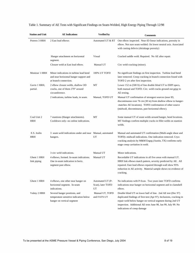
Table 1. Summary of AE Tests with Significant Findings on Seam-Welded, High Energy Piping Through 12/98
Station and Unit
AE Indications
Verified by Comments
Potrero 3 HRH 2 East lead elbows Automated UT & RT One elbow inspected. Near-ID linear indications, porosity in elbow. Not sure seam welded. On lower neutral axis. Associated with casting defects (shrinkage porosity)
Hanger attachment on horizontal segment.
Visual Cracked saddle weld. Repaired. No AE after repair.
Closure weld at East lead elbow. Manual UT Circ weld cracking (minor).
Montour 1 HRH Minor indications in turbine lead bend and near horizontal hanger support and at branch connection.
100% UT TOFD No significant findings on first inspection. Turbine lead bend later removed. Creep cracking in branch connection found with TOFD 2 yrs after first inspection.
Gavin 1 HRH, partial.
2 elbow closure welds, shallow OD cracks, one of them 270° around circumference.
MT Lower 152 m (500 ft) of line double blind UT to ERPI specs, both manual and TOFD. Circ. weld cracks ground out prior to AE testing.
2 indications, turbine leads, in seam. Manual, TOFD UT Manual UT confirmation of strongest sources (near ID, discontinuous over 76 cm (30 in) from shallow elbow to hanger--matches AE locations). TOFD confirmation of other source (midwall, discontinuous, past horizontal elbow).
Coal Unit 2 HRH
7 stantions (Hanger attachments). Cooldown only--no online indications.
MT Some manual UT of seam welds around hanger, bend locations. MT findings confirm multiple cracks in fillet welds on stantion welds.
E.S. Joslin HRH
3 seam weld indications under and near hangers.
Manual, automated UT
Manual and automated UT confirmation (Multi-angle shear and TOFD)--midwall indications. One indication removed. Cryo-cracking analysis by M&M Engrg (Austin, TX) confirms early stage creep cavitation in weld.
3 circ weld indications. Manual UT Minor indications.
Ghent 1 HRH link piping
4 elbows, formed. In-seam indications. One in-seam indication in horiz. segment past elbow.
Manual UT Recordable UT indications in all five areas with manual UT. HRH link elbows match pattern, severity predicted by AE. All repaired. East lead elbows repaired through-wall show 95% reduction in AE activity. Material sample shows no evidence of cracking.
Ghent 1 HRH 4 elbows, one other near hanger on horizontal segment. In-seam indications.
Automated UT (P-Scan), later TOFD UT
No indications with P-Scan. Two years later TOFD confirms indications near hanger on horizontal segment and in clamshell elbow.
Valmy 2 HRH Several hanger positions, and temperature sensitive indication below hanger on vertical segment
Manual UT, TOFD and FATS UT
Double blind UT on lower half of line. 2nd AE test (Dec 97) duplicated findings of first test (Apr 97). Inclusions, cracking in repair weld below hanger on vertical segment during 2nd UT inspection. Additional AE tests June 98, Jan 99, July 99. No indications of creep damage
To be presented at the ASME Pressure Vessel & Piping Conference, San Diego, July 2004 8 of 19

Station and Unit
AE Indications
Verified by Comments
Brown 3 HRH, SH Links
2 main steam leads, in-seam indications.
Automated UT (phased array)
Material removed during Spring 98 outage. One section to EPRI for investigation. No findings with EPRI multi-angle UT procedure. UT phased array finds indications in SH seam weld matching AE locations. Cryo-cracking analysis by M&M Engrg (Austin, TX) shows early stage creep cavitation in mid-weld fusion zone.
Lon C. Hill 4 HRH
Lower level seam weld indications at turbine deck, and batwing hanger indications.
Manual UT, MT Inspection during 3/98. UT confirmed multiple discontinous laminar indications in seam weld at turbine deck location. Batwing hanger indication during startup and cooldown only. Multiple OD-cracks to 7.6 cm (3 in) found in batwing hanger welds (MT).
Horseshoe Lake 7 HRH
5 Elbows, seam weld sources. Manual UT Midwall indications on three elbows to 2.5 cm (1in) long. No material investigation to date.
Batwing hanger attachment welds. Indication shows pressure sensitivity.
MT OD cracks on both hanger and pipe wall sides. AE during online and startup, but not on cooldown.
Navajo 2 Clamshell elbows. Pressure sensitive sources indicating creep damage.
TOFD and FATS UT Prior inspection verified creep damage with UT, metallography. Elbows monitored with AE among lowest ranking damage with UT.
Baldwin 1 4 HRH radiused bends, bends in turbine leads, Y-block welds.
TOFD and FATS UT One clamshell inspected with TOFD and FATS ultrasonics. FATS confirmed early stage creep damage in midwall of extradose weld.
All tests performed to EPRI AE Guidelines standards (Nov 1995)
To be presented at the ASME Pressure Vessel & Piping Conference, San Diego, July 2004 9 of 19

Weld Base Metal
Magnification: 500X
Figure 1. Typical high-temperature creep cracking defects occuring in seam-welded fossil piping systems constructed of P11 or P22 grade steels (top; Foulds et al 1996)). Type IV damage in the fine-grained HAZ typically occurs in subcritically annealed welds, which is more typical of thick-section SH link piping and some HRH piping. Bottom left shows cavitation damage in the cusp region of a HRH double-V weld (Munson et al 1999). Bottom right shows advanced damage in the form of microcracking from a failed long seam bend (Foulds & Carnahan 1997).
To be presented at the ASME Pressure Vessel & Piping Conference, San Diego, July 2004 10 of 19
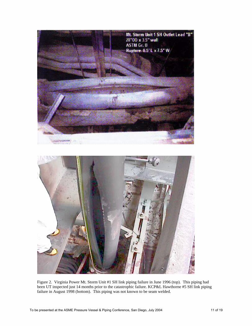
Figure 2. Virginia Power Mt. Storm Unit #1 SH link piping failure in June 1996 (top). This piping had been UT inspected just 14 months prior to the catastrophic failure. KCP&L Hawthorne #5 SH link piping failure in August 1998 (bottom). This piping was not known to be seam welded.
To be presented at the ASME Pressure Vessel & Piping Conference, San Diego, July 2004 11 of 19

Figure 3. Example of an AE waveguide stud welded to a steam pipe. The waveguide serves to isolate the sensor from the hot piping surface, and acts as a sound conductor from the pipe wall to the sensor.
Figure 4. A general depiction of the process of AE detection and location on seam welded high energy piping. High frequency sensors are mounted on welded waveguides at 4.6- 6.1 m (15-20 ft) spacing on the pipe. Detection of signals at adjacent sensor positions, combined with time of arrival calculation, allow the source location of signals along the piping length. Source location cluster analysis is performed to assess the source(s) of the emission and the significance of the findings.
To be presented at the ASME Pressure Vessel & Piping Conference, San Diego, July 2004 12 of 19

Figure 5. A seam-welded clamshell elbow on Illinois Power’s Baldwin #2 HRH line shows typical creep-related AE behavior under cyclic pressure loading (upper left). The mechanism shows high sensitivity to load, and shows a distribution of activity along the elbow that varies with each load cycle (lower left). Bottom right shows the amplitude density feature map of this elbow location. Distributed higher activity sources are evident, and the amplitude dynamic range is larger in the high activity area. Defect growth at this early stage is probably related to decohesion of inclusions that are being affected by the creep process.
To be presented at the ASME Pressure Vessel & Piping Conference, San Diego, July 2004 13 of 19

Pressure Profile
Figure 6. Results of Joslin HRH testing, showing the suspect hanger position (upper right). An 18 cm (7 in) long series of indications were found with both manual UT and multi-angle automated UT under the hanger strap position. The combined sensor UT side-B scan is shown in the bottom center plot. Two significant clusters are identified from the midwall to ID positions, centered ~10 cm (4 in) apart. The AE location vs time results for a 76 cm (30 in) segment encompassing this position is shown at upper left. There are actually several location cluster peaks in this distance, but the two principal peaks correlate well in intensity and location spacing with the two prominent UT indications.
To be presented at the ASME Pressure Vessel & Piping Conference, San Diego, July 2004 14 of 19

Figure 7a. Weld cross-section from Joslin HRH sent to M&M Engineering for metallurgical (cryo-cracking) examination (R. Munson, 1998). The lower weld pass was unusually large, and showed visible segregation. Figure 7b. SEM photo at 5000X of cryo-cracked surface from the lower weld bead (“b” in Figure 7a). There is evidence of visible creep cavitation around inclusions, with the orthogonal shaped features to the cavity associated with early stage creep damage.
To be presented at the ASME Pressure Vessel & Piping Conference, San Diego, July 2004 15 of 19
“A”
“E” “B”
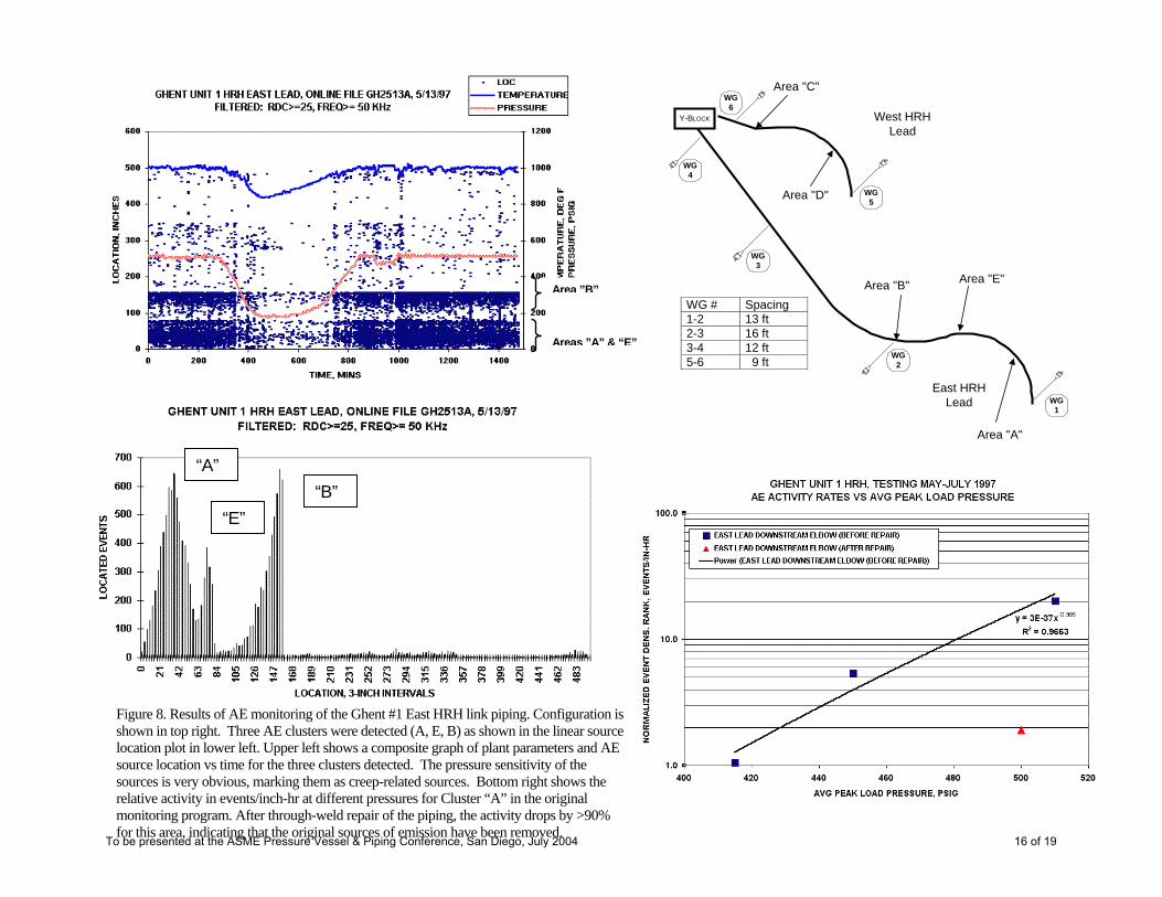
Figure 8. Results of AE monitoring of the Ghent #1 East HRH link piping. Configuration isshown in top right. Three AE clusters were detected (A, E, B) as shown in the linear sourcelocation plot in lower left. Upper left shows a composite graph of plant parameters and AE source location vs time for the three clusters detected. The pressure sensitivity of the sources is very obvious, marking them as creep-related sources. Bottom right shows the relative activity in events/inch-hr at different pressures for Cluster “A” in the original monitoring program. After through-weld repair of the piping, the activity drops by >90% for this area, indicating that the original sources of emissi een removed.
East HRHLead
West HRHLead
Y-BLOCK
WG1
WG2
WG3
WG4
WG5
WG6
Area "A"
Area "B" Area "E"
Area "C"
Area "D"
WG # Spacing1-2 13 ft2-3 16 ft3-4 12 ft5-6 9 ft
Area ”B”
Areas ”A” & “E”
To be presented at the ASME Pressure Vessel & Piping Confe Diego, July 2004 16 of 19
on have brence, San
Penthouse Roof 90
West SH Lead
Figure 9. Results of online AE monitoring of Brown #3 SH West lead link
piping. Top left shows configuration of 3.6 m (12 ft) seam-welded link segment and the location of AE waveguides. Top right shows the source location plot developed during Spring 1998 monitoring. Bottom right shows a composite graph of plant parameters and AE source located events detected. The sources are more active at high pressure, indicating they are creep-related sources. The AE location cluster is just below the penthouse roof.
To be presented at the ASME Pressure Vessel & Piping Conference, San Diego, July 2004 17 of 19
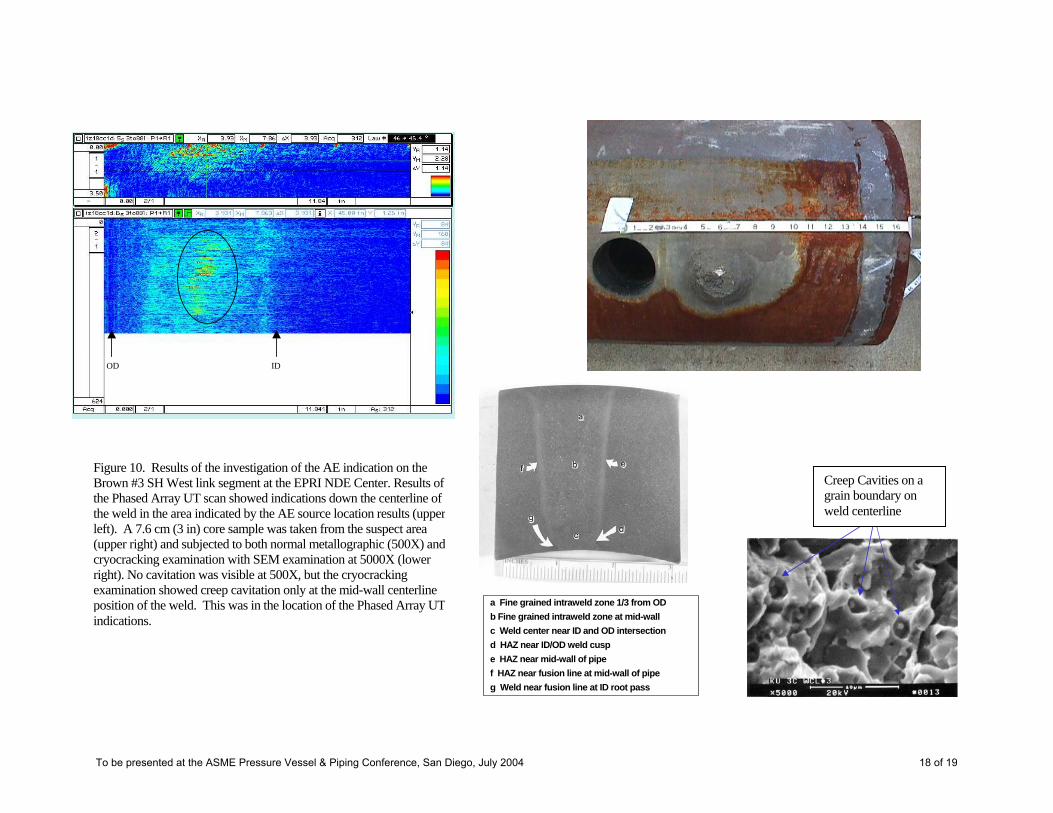
OD ID
Creep Cavities on a grain boundary on weld centerline
f HAZ near fusion line at mid-wall of pipeg Weld near fusion line at ID root pass
c Weld center near ID and OD intersectiond HAZ near ID/OD weld cusp e HAZ near mid-wall of pipe
b Fine grained intraweld zone at mid-walla Fine grained intraweld zone 1/3 from OD
Figure 10. Results of the investigation of the AE indication on the Brown #3 SH West link segment at the EPRI NDE Center. Results of the Phased Array UT scan showed indications down the centerline of the weld in the area indicated by the AE source location results (upperleft). A 7.6 cm (3 in) core sample was taken from the suspect area (upper right) and subjected to both normal metallographic (500X) andcryocracking examination with SEM examination at 5000X (lower right). No cavitation was visible at 500X, but the cryocracking examination showed creep cavitation only at the mid-wall centerline position of the weld. This was in the location of the Phased Array UTindications.
To be presented at the ASME Pressure Vessel & Piping Conference, San Diego, July 2004 18 of 19

Intradose WeldLSW4I53.5"
Extradose WeldLSW4E
110"
Girth WeldGS-11
Elbow HRF4
CS Hanger(U-bolt clamp)
Seam WeldLSW9
Spool HR9 WG#15
Spool HR8
Girth Weld GF-10
Seam Weld LSW8
WG#14 Illinois Power
Baldwin Unit #1Elev 553
Clamshell Elbow
Focused Array UTInspection
48-50"From GF-10
101-103"from GF-10
24"
16" 56"
Centerline distanceWG #14 to WG #15 = 192"
0LOCATION, 6-INCH INTERVALS
ILLINOIS POWER BALDWIN UNIT #1 HRH, WG'S 14-21, FILE BA1511A ONLINE: 3:45 PM 5/11/98 TO 2:48 AM 5/14/98
FILTERED: RDC>=25, FREQ>= 50 KHz
50
100
150
200
250
LOC
ATE
D E
VEN
TS
OD ID
C-Scan
Side B-Scan
End B-Scan
Figure 11. Results of Baldwin #1 HRH AE monitoring and follow-up UT inspectionwith TOFD and FATS UT methods. Two clamshell elbows show emission characteristic of early creep damage (upper right). The upstream elbow and a portion of the downstream piping between waveguides 14-15 was inspected 100% with TOFD, and spot checked with FATS UT in several areas (top right). No indications of creep damage were identified with the TOFD inspection. The AE source location results were used as guidance to inspect a midspan location on the extradose seam weld of the clamshell elbow. Evidence of early stage creep damage was identified with the FATS UT scan of a 5 cm (2 in) weld segment (bottom right).The C-scan image shows a fog of dots that are characteristic of cavitation clusters. The side B-scan shows these are at the mid-wall location, at the expected location of the double V weld cusp. The end B-scan image shows the cluster of indications falling along the expected fusion line of the weld.
To be presented at the ASME Pressure Vessel & Piping Conference, San Diego, July 2004 19 of 19


![SENTRO - Acoustic Emission Presentation [2016]](https://img.pdfslide.us/doc/110x75/5875c8511a28ab33128b6abf/sentro-acoustic-emission-presentation-2016.jpg)