Embed Size (px)
Citation preview
Standardization and System integration of Smart Antennas
intoWireless Networks
Adrian Boukalov
Helsinki University of Technology
Communications Lab
ETSI/MESA meeting
Content
1.Smart antennas. Benefactors. Operators perspective. User perspective.
2. Overview of communication systems with Smart Antennas (SA).
3. Basics of Smart Antennas Techniques. SA types, classification.
4. Integrated receiver design with SA.
5. Impact of mobility, propagation environment and interference on
SA applicability and performance.
6. Air interface spec and SA compatibility/performance.Standardization
related issues
7. Wireless network performance and planning with SA.
8. Current status and future evolution of SA techniques.
9. SA system integration: Problems Solutions
10. SA system integration research at ComLab/HUT
"Spatial Processing remains as the most promising, if not the last frontier, in the evolution of multiple access systems" Andrew Viterbi
There are very few techniques proposedtoday, which are able to improve radio networkperformance dramatically- Spatial processing- Multi-user detection- Channel reuse based on polarization - Advanced network controlSpatial processing is among them and can be effectively combined with others techniques
How smart should be Smart Antennas techniques ?
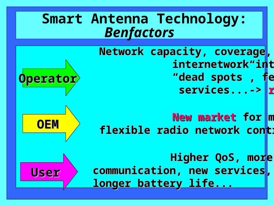
Smart Antenna Technology: Benfactors
Network capacity, coverage, less Network capacity, coverage, less internetwork interference, filling internetwork interference, filling “ “dead spots”, fewer BSs,QoS, new dead spots”, fewer BSs,QoS, new services...-> services...-> revenuesrevenues
New marketNew market for more advanced BSs, for more advanced BSs, flexible radio network control... flexible radio network control...
Higher QoS, more reliable, secureHigher QoS, more reliable, secure communication, new services,communication, new services, longer battery life... longer battery life...
OperatorOperator
OEMOEM
UserUser
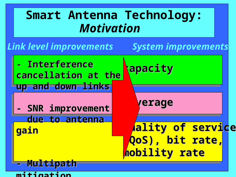
Smart Antenna Technology:Motivation
- Interference cancellation - Interference cancellation at the up and down links at the up and down links
- SNR improvement - SNR improvement due to antenna gain due to antenna gain
- Multipath mitigation - Multipath mitigation
capacitycapacity
coveragecoverage
Quality of serviceQuality of service(QoS), bit rate, (QoS), bit rate, mobility ratemobility rate
Link level improvements System improvements
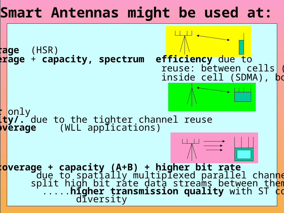
Smart Antennas might be used at:
- A. BS only up-link…………..coverage (HSR) &down-link…..…coverage + capacity, spectrum efficiency due to reuse: between cells (SFIR), due to reuse inside cell (SDMA), both SDMA+SFIR
- B. MS/subscriber only up-link……………capacity/. due to the tighter channel reuse &down-link……....coverage (WLL applications)
- C. Both ends MS and BS simultaneously…..coverage + capacity (A+B) + higher bit rate up-link & due to spatially multiplexed parallel channels and down-link split high bit rate data streams between them or .....higher transmission quality with ST coded diversity
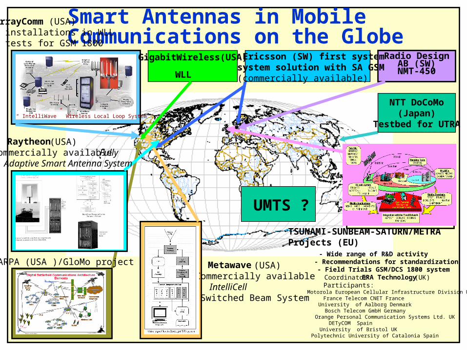
Smart Antennas in Mobile Communications on the Globe
Radio Design AB (SW)
NMT-450
TSUNAMI-SUNBEAM-SATURN/METRA Projects (EU)
- Wide range of R&D activity- Recommendations for standardization- Field Trials GSM/DCS 1800 systemCoordinator ERA Technology (UK)Participants:
Motorola European Cellular Infrastructure Division UKFrance Telecom CNET FranceUniversity of Aalborg DenmarkBosch Telecom GmbH GermanyOrange Personal Communication Systems Ltd. UKDETyCOM SpainUniversity of Bristol UKPolytechnic University of Catalonia Spain
ArrayComm (USA)- installations in WLL - tests for GSM 1800
Metawave (USA)Commercially availableIntelliCellSwitched Beam System
ARPA (USA )/GloMo project
Raytheon (USA)Commercially available FullyAdaptive Smart Antenna System
Ericsson (SW) first system system solution with SA GSM (commercially available)
“ IntelliWave” Wireless Local Loop System
NTT DoCoMo(Japan)
Testbed for UTRA
GigabitWireless(USA)
WLL
UMTS ?
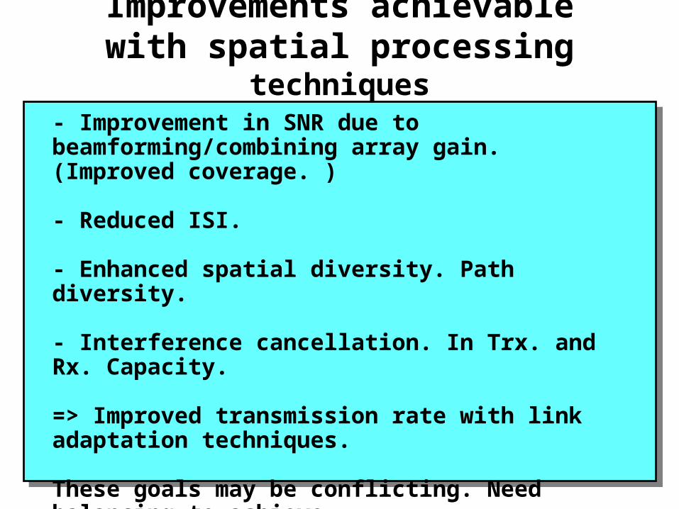
Improvements achievable with spatial processing techniques
- Improvement in SNR due to beamforming/combining array gain. (Improved coverage. )
- Reduced ISI.
- Enhanced spatial diversity. Path diversity.
- Interference cancellation. In Trx. and Rx. Capacity.
=> Improved transmission rate with link adaptation techniques.
These goals may be conflicting. Need balancing to achieve synergy with propagation environment, offered traffic, infrastructure !
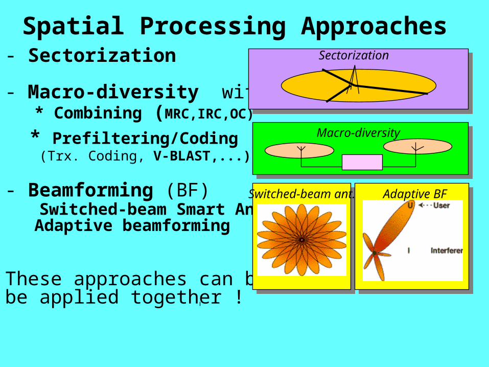
- Sectorization
- Macro-diversity with: * Combining (MRC,IRC,OC)
* Prefiltering/Coding (Trx. Coding, V-BLAST,...)
- Beamforming (BF) Switched-beam Smart Antenna Adaptive beamforming
These approaches can be/should be applied together !
Spatial Processing Approaches
Macro-diversity
Switched-beam ant. Adaptive BF
Sectorization
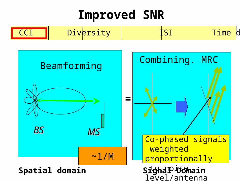
SNR CCI Diversity ISI Time domain diversity
Improved SNR
BSBS MSMS
Beamforming
~1/M
Combining. MRC
Co-phased signals weighted proportionally to noise level/antenna
=
Spatial domain Signal Domain
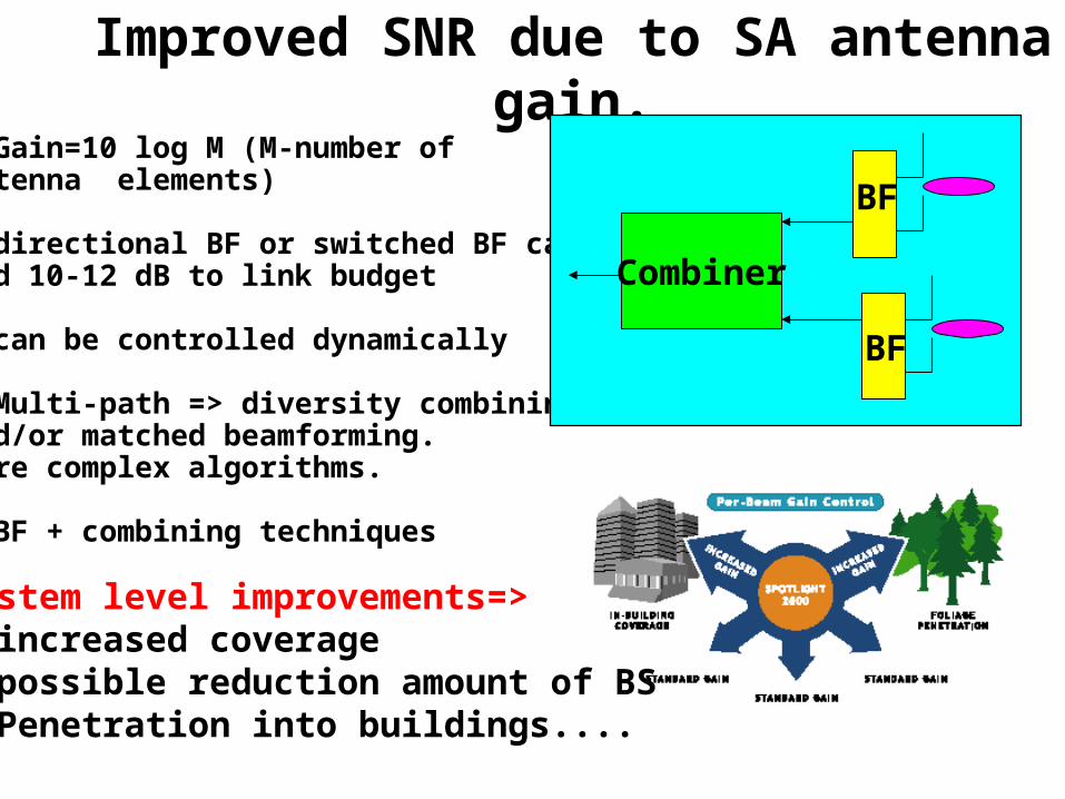
Improved SNR due to SA antenna gain.- Gain=10 log M (M-number of antenna elements)
- directional BF or switched BF can add 10-12 dB to link budget
- can be controlled dynamically
- Multi-path => diversity combining and/or matched beamforming.More complex algorithms.
- BF + combining techniques
BF
BF
Combiner
System level improvements=>- increased coverage- possible reduction amount of BS - Penetration into buildings....
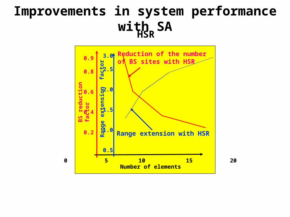
Improvements in system performance with SA
BS
red
uct
ion
fa
ctor
Reduction of the number of BS sites with HSR
Number of elements0 5 10 15 20
0.9
0.8
0.6
0.4
0.2
Ran
ge e
xten
sion
fac
tor
3.0
2.5
2.0
1.5
1.0
0.5
Range extension with HSR
HSR
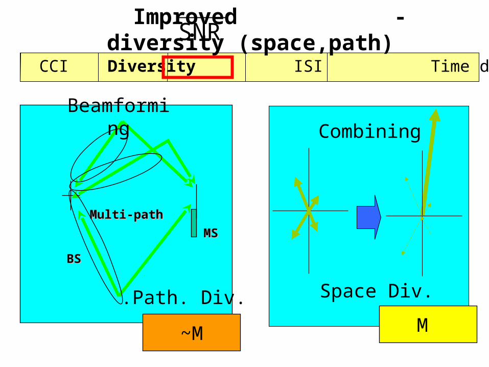
SNR CCI Diversity ISI Time domain diversity
Improved - diversity (space,path)
Multi-pathMulti-path
BSBS
MS MS
Beamforming
.Path. Div.
Combining
Space Div.
~M M
SNR
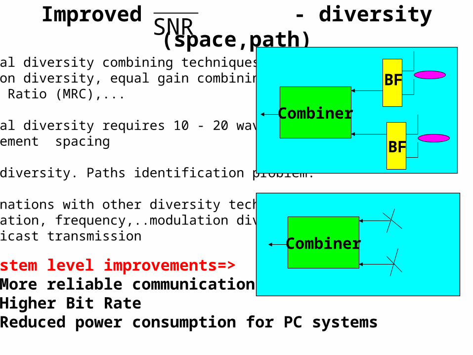
Improved - diversity (space,path)
- Spatial diversity combining techniques:Selection diversity, equal gain combining, Maximum Ratio (MRC),...
- Spatial diversity requires 10 - 20 wavelengthinterelement spacing
- Path diversity. Paths identification problem.
- Combinations with other diversity techniques.polarization, frequency,..modulation diversity in multicast transmission
BF
BF
Combiner
SNR
CombinerSystem level improvements=>- More reliable communication- Higher Bit Rate- Reduced power consumption for PC systems
SNR CCI Diversity ISI Time domain diversity
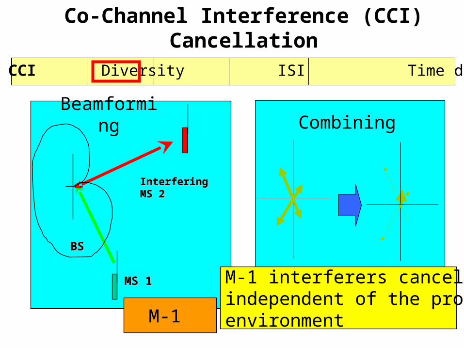
Co-Channel Interference (CCI) Cancellation
BSBS
MS 1MS 1
Interfering Interfering MS 2MS 2
Beamforming Combining
M-1
M-1 interferers cancellation.independent of the propagationenvironment
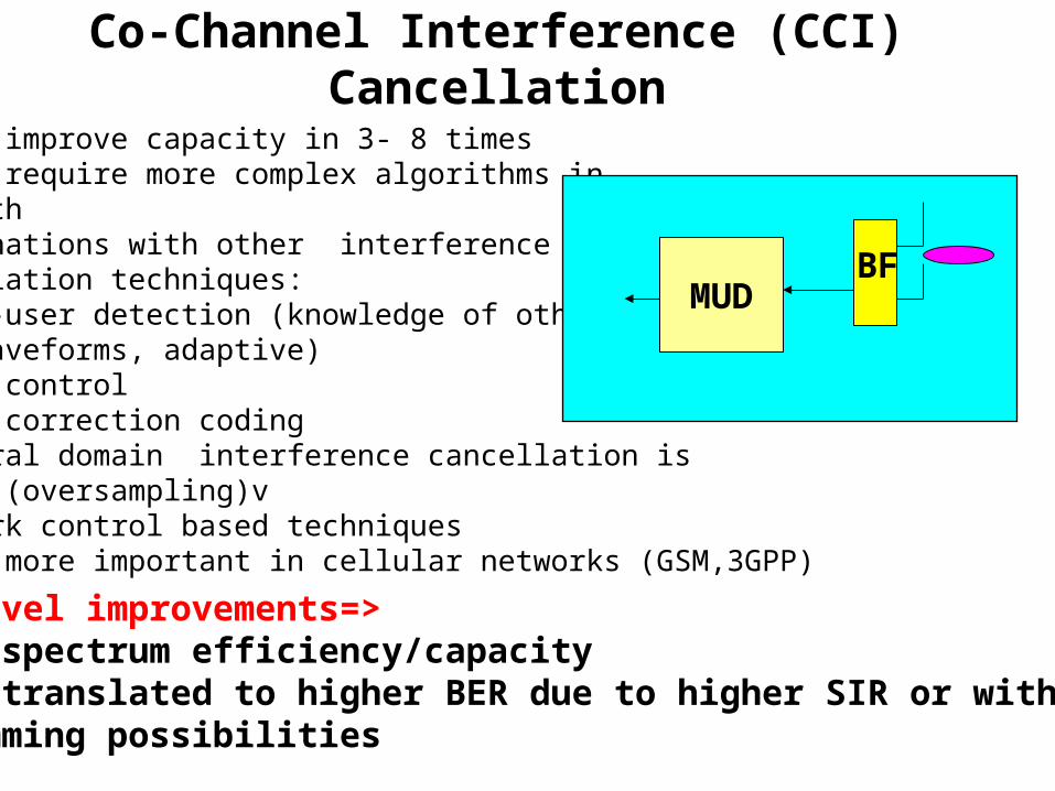
Co-Channel Interference (CCI) Cancellation
- might improve capacity in 3- 8 times- might require more complex algorithms in multipath- Combinations with other interference cancellation techniques:* Multi-user detection (knowledge of other users waveforms, adaptive)* Power control* Error correction coding* Temporal domain interference cancellation is limited (oversampling)v* network control based techniques - IC is more important in cellular networks (GSM,3GPP)
BFMUD
System level improvements=>- higher spectrum efficiency/capacity- can be translated to higher BER due to higher SIR or with more ch.- antijamming possibilities
SNR CCI Diversity ISI Time domain diversity
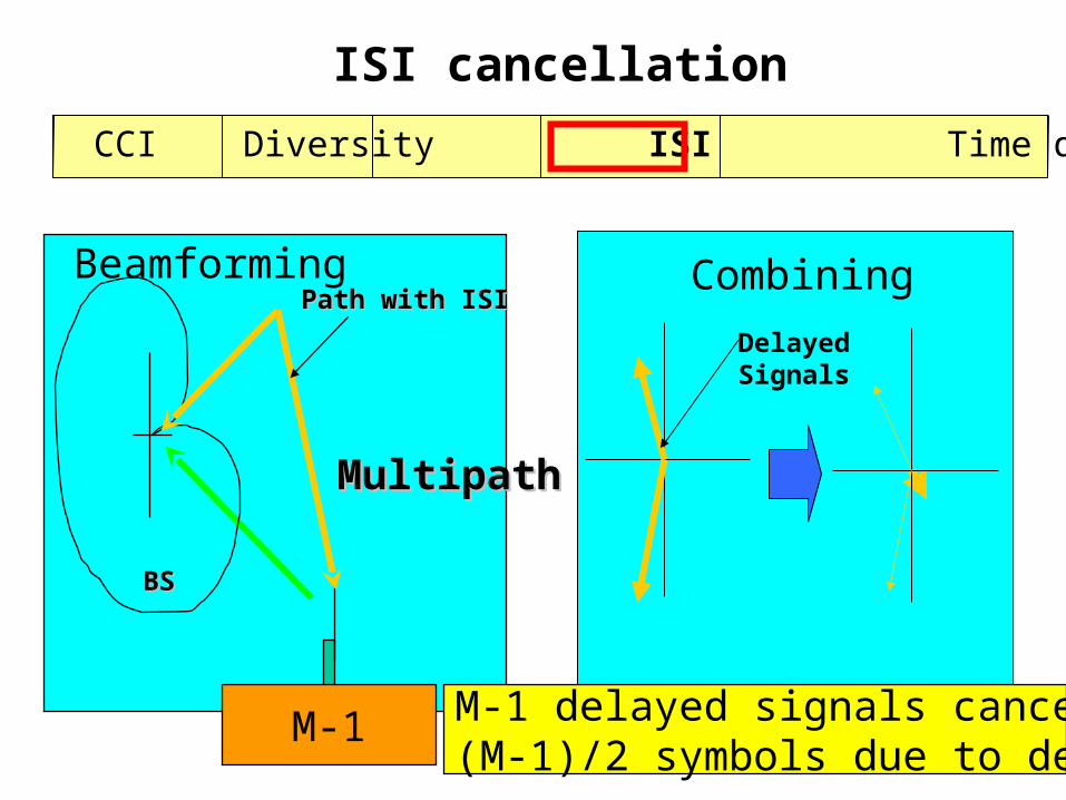
ISI cancellation
Delayed Signals
Combining
MultipathMultipath
BSBS
Path with ISIPath with ISIBeamforming
M-1 M-1 delayed signals cancellation(M-1)/2 symbols due to delay spread
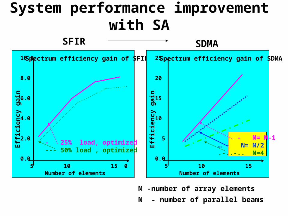
System performance improvement with SA
0 5 10 15 20
10.0
8.0
6.0
4.0
2.0
0.0
Number of elements
Spectrum efficiency gain of SFIR
Eff
icie
ncy
gai
n
- 25% load, optimized--- 50% load , optimized
SFIR
0 5 10 15 20
25
20
15
10
5
0.0
Number of elements
Spectrum efficiency gain of SDMA
Eff
icie
ncy
gai
n
SDMA
- N= M-1… - N= M/2.-..-.. N=4
M -number of array elements
N - number of parallel beams

ISI cancellation- spatial domain - only interferencecancellation is possible
- preferably to combine with temporal domain techniques (preserves signal energy, diversity,more efficient)
- decoupled/joint space time processing
- ZF, MMSE, MLSE joint/decoupled S-T equalizers
BF wEqualizer
ZF,MMSE,MLSE BF
w
S-T EqualizerZF,MMSE,
MLSESystem level improvements=>- Higher BER - Improved reliability- Improved performance in Multipath
SNR CCI Diversity ISI Time domain diversity
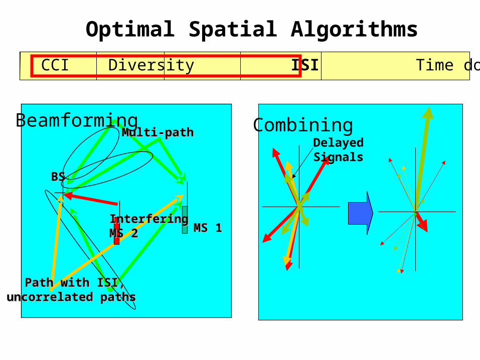
Optimal Spatial Algorithms
BSBS
MS 1MS 1
Multi-pathMulti-path
Interfering Interfering MS 2MS 2
Path with ISI,Path with ISI,uncorrelated paths uncorrelated paths
BeamformingDelayed Signals
Combining
SNR CCI Diversity ISI Time domain diversity
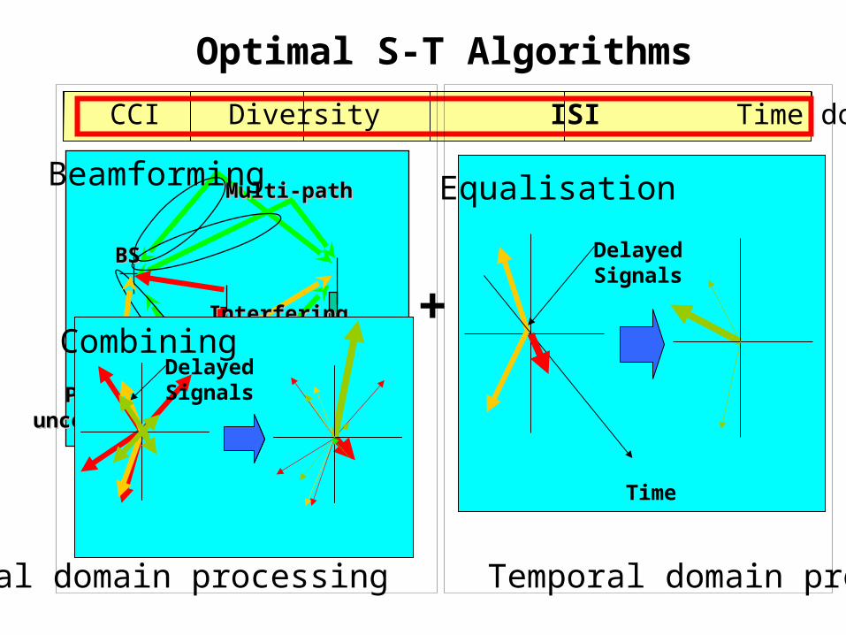
Optimal S-T Algorithms
BSBS
MS 1MS 1
Multi-pathMulti-path
Interfering Interfering MS 2MS 2
Path with ISI,Path with ISI,uncorrelated paths uncorrelated paths
Beamforming
Delayed Signals
Combining
Delayed Signals
Time
+
Spatial domain processing Temporal domain processing
Equalisation
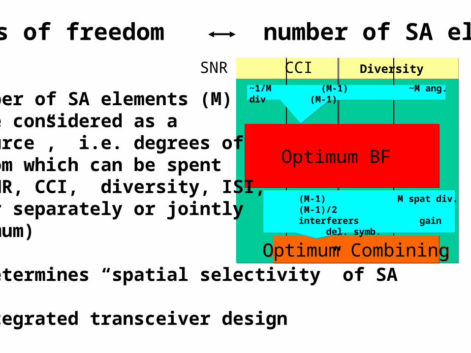
SNR CCI Diversity ISI
Optimum CombiningOptimum Combining
~1/M (M-1) ~M ang. div (M-1)
Optimum BF Optimum BF
(M-1) M spat div. (M-1)/2 interferers gain del. symb.
- Number of SA elements (M) can be considered as a “resource”, i.e. degrees offreedom which can be spent for SNR, CCI, diversity, ISI,either separately or jointly(optimum)
- M determines “spatial selectivity” of SA
=> Integrated transceiver design
Degrees of freedom number of SA elements
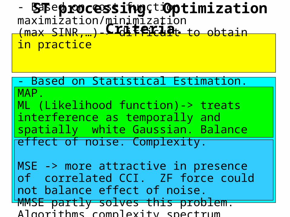
ST processing. Optimization Criteria. - Based on cost function maximization/minimization (max SINR,…)-> difficult to obtain in practice
- Based on Statistical Estimation. MAP.ML (Likelihood function)-> treats interference as temporally and spatially white Gaussian. Balance effect of noise. Complexity.
MSE -> more attractive in presence of correlated CCI. ZF force could not balance effect of noise.MMSE partly solves this problem. Algorithms complexity spectrum efficiency. Blind methods.
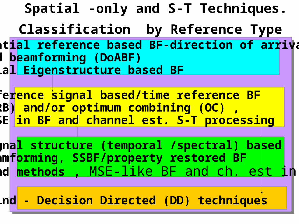
Spatial -only and S-T Techniques. Classification
by Reference Type - Spatial reference based BF-direction of arrival based beamforming (DoABF)Spatial Eigenstructure based BF
- Reference signal based/time reference BF (TRB) and/or optimum combining (OC) , MMSE in BF and channel est. S-T processing
- Signal structure (temporal /spectral) based beamforming, SSBF/property restored BF blind methods , MSE-like BF and ch. est in STP
- Blind - Decision Directed (DD) techniques
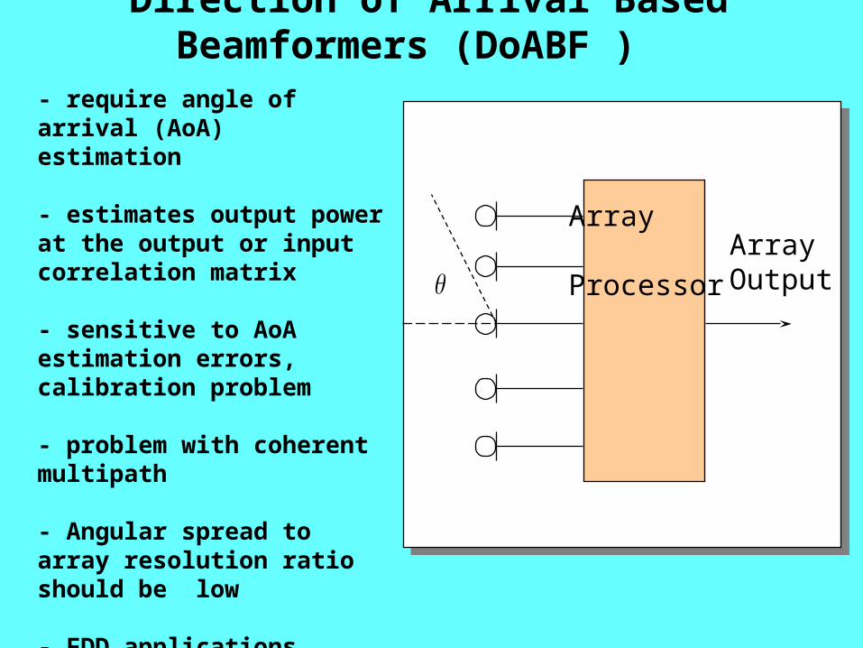
Direction of Arrival Based Beamformers (DoABF )
- require angle of arrival (AoA)estimation
- estimates output power at the output or input correlation matrix
- sensitive to AoA estimation errors, calibration problem
- problem with coherent multipath
- Angular spread toarray resolution ratio should be low
- FDD applications
- some methods of AoA estimation might be problematic in CDMA
Array
ProcessorArray Output
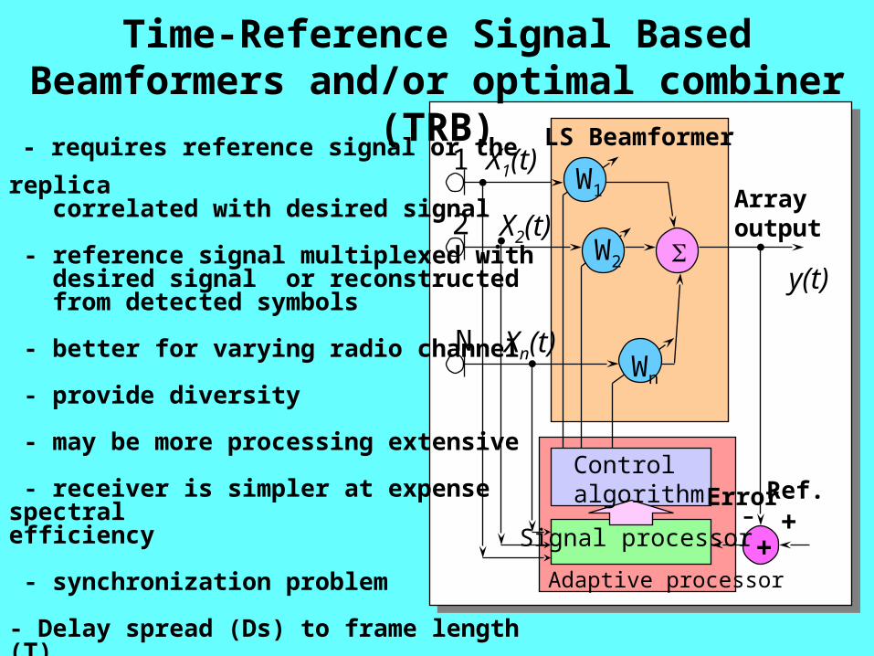
Time-Reference Signal Based Beamformers and/or optimal combiner (TRB)
- requires reference signal or the replica correlated with desired signal
- reference signal multiplexed with desired signal or reconstructed from detected symbols
- better for varying radio channel
- provide diversity
- may be more processing extensive
- receiver is simpler at expense spectral efficiency
- synchronization problem
- Delay spread (Ds) to frame length (T) ratio should be low
- TDD applications
LS Beamformer
W1
W2
Wn
+
Arrayoutput
Error- +
Ref.
y(t)
X1(t)
X2(t)
Xn(t)
Controlalgorithm
Signal processor
1
2
N
Adaptive processor
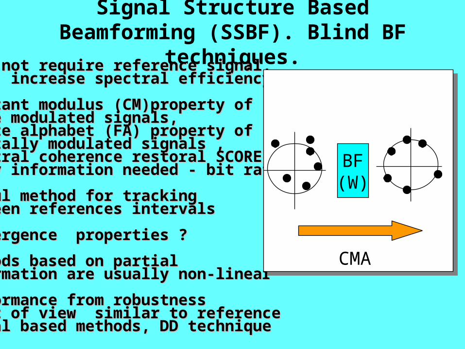
Signal Structure Based Beamforming (SSBF). Blind BF techniques.
- Does not require reference signal,- Does not require reference signal, thus increase spectral efficiencythus increase spectral efficiency
- constant modulus (CM)property of- constant modulus (CM)property of phase modulated signals, phase modulated signals, - finite alphabet (FA) property of - finite alphabet (FA) property of digitally modulated signals ,digitally modulated signals ,- spectral coherence restoral SCORE- spectral coherence restoral SCORE (only information needed - bit rate) (only information needed - bit rate)
- useful method for tracking- useful method for tracking between references intervals between references intervals
- convergence properties ?- convergence properties ?
- methods based on partial - methods based on partial information are usually non-linearinformation are usually non-linear
- performance from robustness- performance from robustness point of view similar to referencepoint of view similar to reference signal based methods, DD technique signal based methods, DD technique
BF(W)
CMA
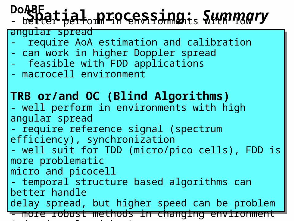
Spatial processing: SummaryDoABF- better perform in environments with low angular spread- require AoA estimation and calibration- can work in higher Doppler spread- feasible with FDD applications- macrocell environment
TRB or/and OC (Blind Algorithms)- well perform in environments with high angular spread- require reference signal (spectrum efficiency), synchronization- well suit for TDD (micro/pico cells), FDD is more problematic micro and picocell- temporal structure based algorithms can better handledelay spread, but higher speed can be problem- more robust methods in changing environment (adaptive algorithms)
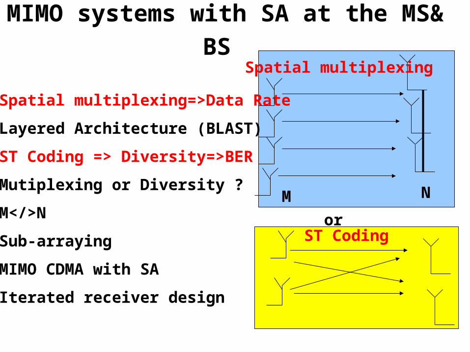
MIMO systems with SA at the MS& BS
- Spatial multiplexing=>Data Rate
- Layered Architecture (BLAST)
- ST Coding => Diversity=>BER
- Mutiplexing or Diversity ?
- M</>N
- Sub-arraying
- MIMO CDMA with SA
- Iterated receiver design
or
M N
Spatial multiplexing
ST Coding
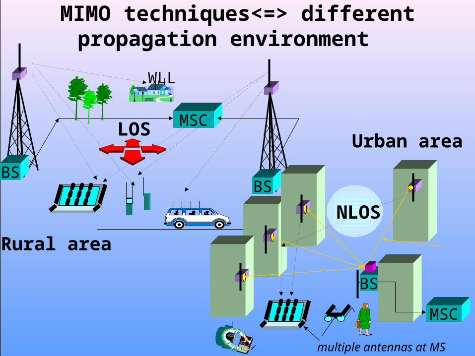
MSC
BSBS
WLL
LOS
MSC
BS
multiple antennas at MS
NLOS
MIMO techniques<=> different propagation environment
Urban area
Rural area
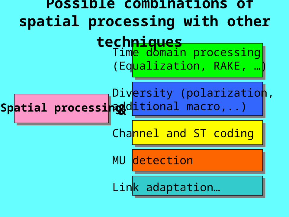
Possible combinations of spatial processing
with other techniques Time domain processing(Equalization, RAKE, …)
Diversity (polarization, additional macro,..)
Channel and ST coding
MU detection
Link adaptation…
Spatial processing
&
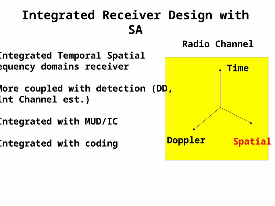
Integrated Receiver Design with SA
- Integrated Temporal SpatialFrequency domains receiver
- More coupled with detection (DD, Joint Channel est.)
- Integrated with MUD/IC
- Integrated with coding
Radio Channel
Time
Doppler Spatial
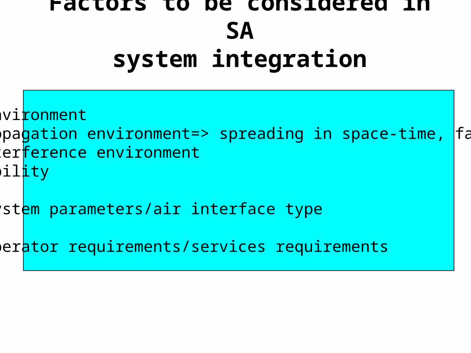
Factors to be considered in SAsystem integration
A. Environment - propagation environment=> spreading in space-time, fading- interference environment- mobility
B. System parameters/air interface type
C. Operator requirements/services requirements

SA Integration into Cellular Networks
Smart Ant. Tech.
Network Planning
- Capacity, coverage, interference planning- Joint fixed and radio network optimization, planning- System upgrade, economical issues
Network control- R.resource management - call control
Radio Interface
Receiver structure,Tx, Rx algorithms
- Spatial proc.- Time domain proc.- Coding- Detection- Diversity- ………..
Air Interface- Multiple access- Duplexing- Modulation- Framing- Availability of pilots
DSP tech.
SWRadio
Radio NetworkManagement
Link level control
- Power Control - Quality Control- Tracking
Cell control- admission control- broadcast channel control- handover control- macro-diversity control
Services -> MS location
3G
2.5G
2G
1G
1G- analog systems2G- digital systems 2.5G- digital+packet +.. (GPRS,..)3G - W-CDMA4G- cellular+ gigabit WLAN
4G
After A.Paulraj
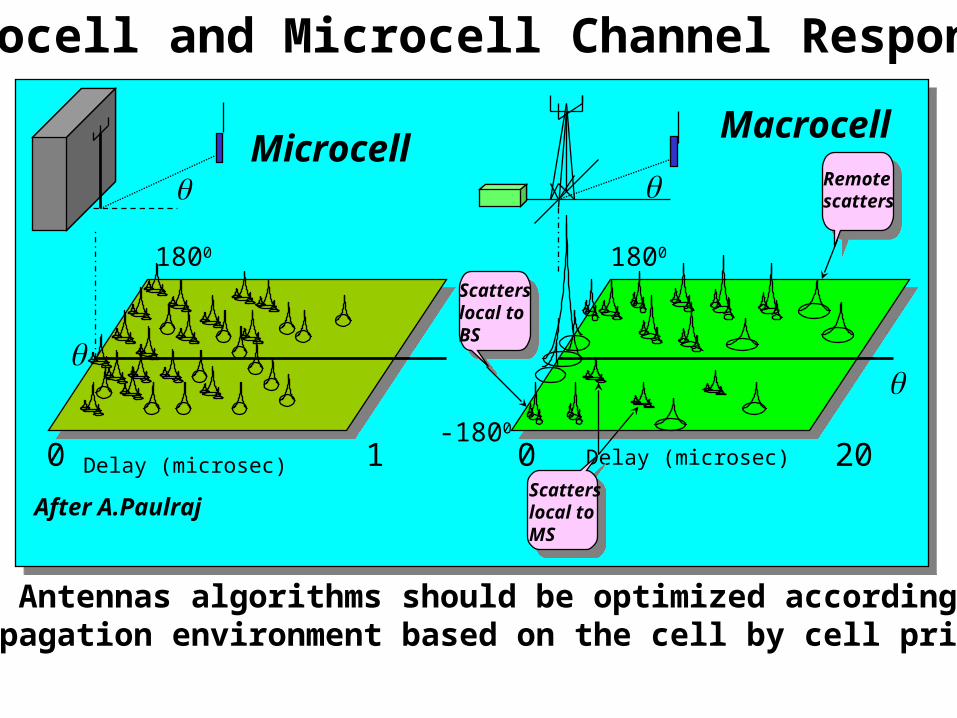
Macrocell and Microcell Channel Response
MicrocellMacrocell
Delay (microsec)0 1 0 20
-1800
1800
1800
Delay (microsec)
Remotescatters
Scatterslocal toBS
Scatterslocal toMS
- Smart Antennas algorithms should be optimized according tothe propagation environment based on the cell by cell principle
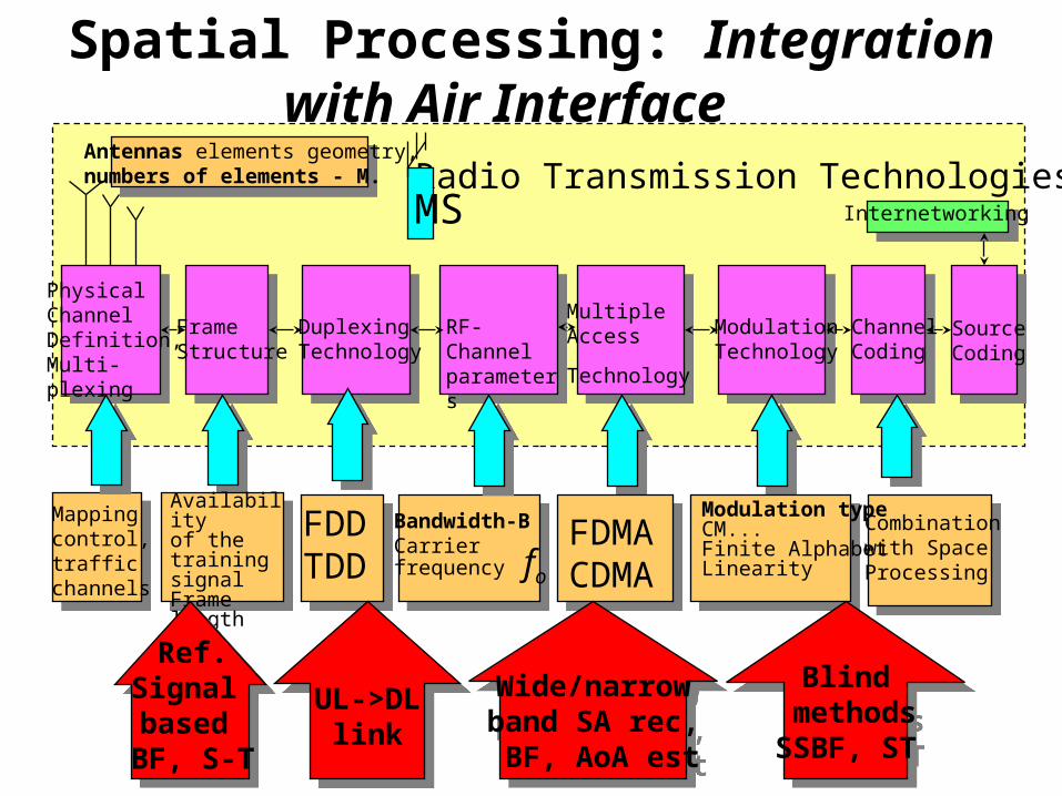
Spatial Processing: Integration with Air Interface
Mappingcontrol,traffic channels
PhysicalChannelDefinition,Multi-plexing
FrameStructure
DuplexingTechnology
RF- Channelparameters
MultipleAccess
Technology ChannelCoding
SourceCoding
Internetworking
ModulationTechnology
FDMACDMA
FDDTDD
Availabilityof the trainingsignalFrame length - T
Modulation typeCM...Finite Alphabet Linearity
Combinationwith Space Processing
Bandwidth-BCarrierfrequency fo
Antennas elements geometry,numbers of elements - M. Radio Transmission Technologies
UL->DLlink
UL->DLlink
Wide/narrowband SA rec, BF, AoA est
Wide/narrowband SA rec, BF, AoA est
Blind methodsSSBF, ST
Blind methodsSSBF, ST
MS
Ref.Signal based
BF, S-T
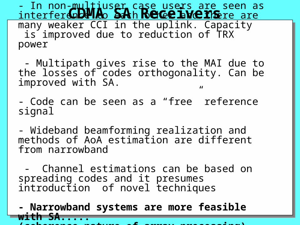
- In non-multiuser case users are seen as interference to each other and there are many weaker CCI in the uplink. Capacity is improved due to reduction of TRX power
- Multipath gives rise to the MAI due to the losses of codes orthogonality. Can be improved with SA.
- Code can be seen as a “free” reference signal
- Wideband beamforming realization and methods of AoA estimation are different from narrowband
- Channel estimations can be based on spreading codes and it presumes introduction of novel techniques
- Narrowband systems are more feasible with SA.....(coherence nature of array processing)
CDMA SA Receivers
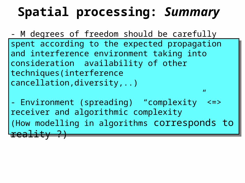
Spatial processing: Summary
- M degrees of freedom should be carefully spent according to the expected propagation and interference environment taking into consideration availability of other techniques(interference cancellation,diversity,..)
- Environment (spreading) “complexity” <=> receiver and algorithmic complexity (How modelling in algorithms corresponds to reality ?)
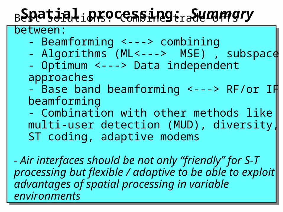
Spatial processing: Summary
Best solutions: Combine trade-offs between:- Beamforming <---> combining - Algorithms (ML<---> MSE) , subspace- Optimum <---> Data independent approaches- Base band beamforming <---> RF/or IF beamforming - Combination with other methods like multi-user detection (MUD), diversity, ST coding, adaptive modems
- Air interfaces should be not only “friendly” for S-Tprocessing but flexible / adaptive to be able to exploit advantages of spatial processing in variable environments
- Integrated S-T MUD .... transceiver design...
Spatial processing: Summary
Smart Antennas might be not very smart (Complexity) Integrated but relatively simple system design can provide considerable improvement with low level of complexity
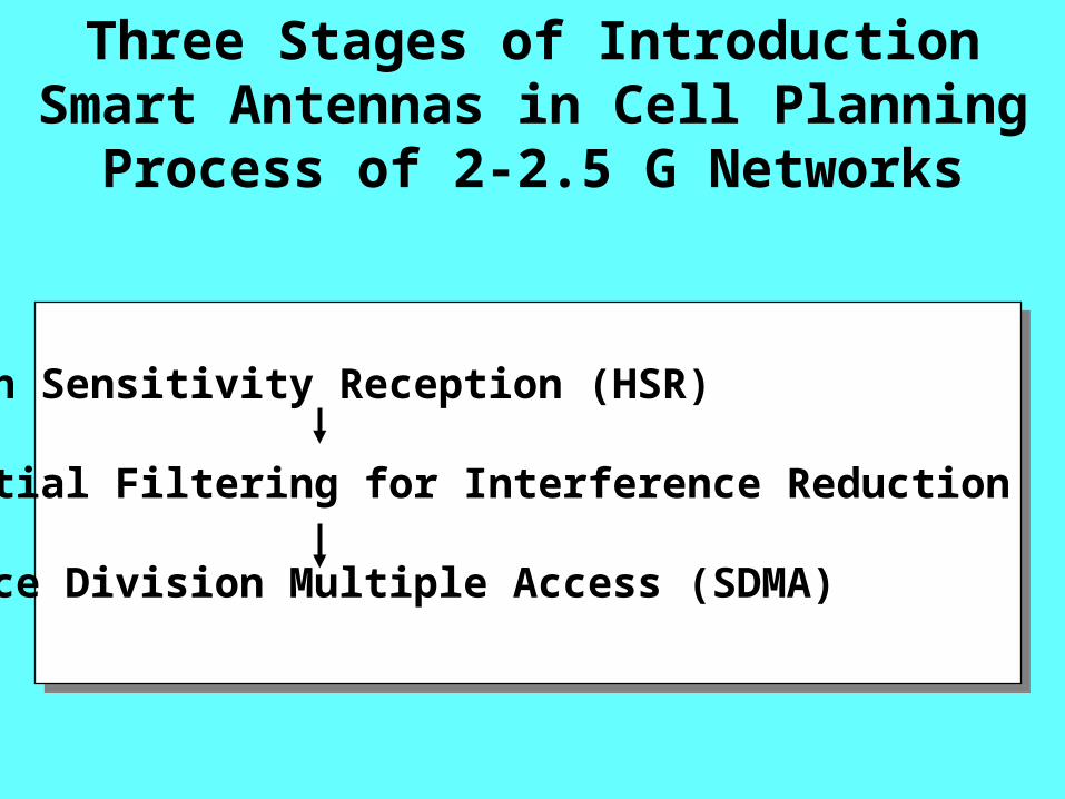
Three Stages of Introduction Smart Antennas in Cell Planning Process of 2-2.5 G Networks
1. High Sensitivity Reception (HSR)
2. Spatial Filtering for Interference Reduction (SFIR)
3. Space Division Multiple Access (SDMA)
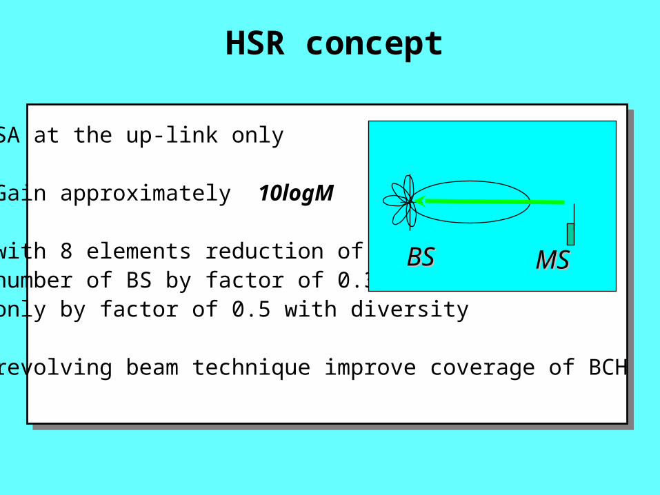
HSR concept
- SA at the up-link only
- Gain approximately 10logM
- with 8 elements reduction of number of BS by factor of 0.3 only by factor of 0.5 with diversity
- revolving beam technique improve coverage of BCH
BSBS MSMS
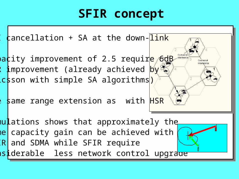
- CCI cancellation + SA at the down-link
- capacity improvement of 2.5 require 6dB CIR improvement (already achieved by Ericsson with simple SA algorithms)
- the same range extension as with HSR
- simulations shows that approximately the same capacity gain can be achieved with SFIR and SDMA while SFIR require considerable less network control upgrade
SFIR concept
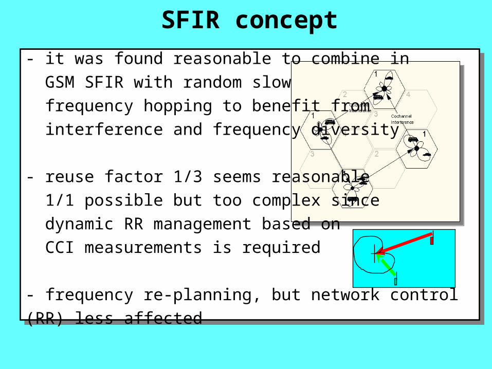
- it was found reasonable to combine in
GSM SFIR with random slow
frequency hopping to benefit from
interference and frequency diversity
- reuse factor 1/3 seems reasonable
1/1 possible but too complex since
dynamic RR management based on
CCI measurements is required
- frequency re-planning, but network control (RR) less affected
SFIR concept
SDMA concept
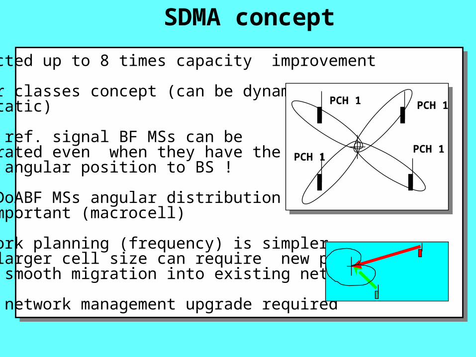
- expected up to 8 times capacity improvement
- power classes concept (can be dynamic or static)
- with ref. signal BF MSs can be separated even when they have the same angular position to BS !
- for DoABF MSs angular distribution is important (macrocell) - network planning (frequency) is simpler, but larger cell size can require new planning, more smooth migration into existing network
- more network management upgrade required
PCH 1 PCH 1
PCH 1PCH 1
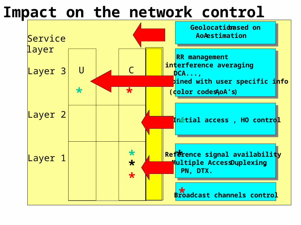
Impact on the network control
U C
Servicelayer
Layer 3
Layer 2
Layer 1
RR managementinterference averaging DCA..., combined with user specific info
(color codes, AoA’s)
Geolocation based on AoA estimation
Reference signal availabilityMultiple Access , Duplexing,PN, DTX.
Initial access , HO control
Broadcast channels control
*
*
**
*
*
*
*
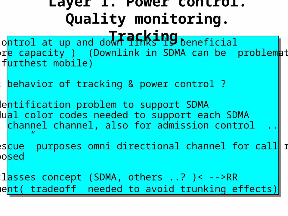
Layer 1. Power control. Quality monitoring. Tracking.
- power control at up and down links is beneficial (60% more capacity ) (Downlink in SDMA can be problematic due to furthest mobile)
- dynamic behavior of tracking & power control ?
- user identification problem to support SDMA individual color codes needed to support each SDMA traffic channel channel, also for admission control ..
- for “rescue” purposes omni directional channel for call recovery is proposed
- power classes concept (SDMA, others ..? )< -->RR management( tradeoff needed to avoid trunking effects)
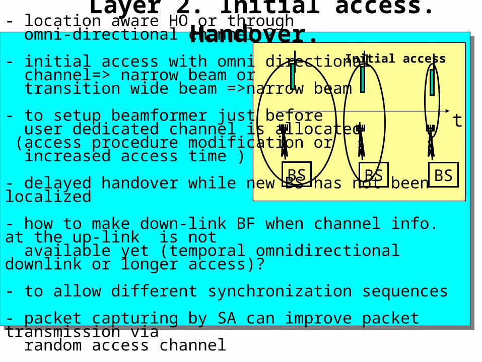
Layer 2. Initial access. Handover.- location aware HO or through omni-directional channel ?
- initial access with omni directional channel=> narrow beam or transition wide beam =>narrow beam
- to setup beamformer just before user dedicated channel is allocated (access procedure modification or increased access time )
- delayed handover while new BS has not been localized
- how to make down-link BF when channel info. at the up-link is not available yet (temporal omnidirectional downlink or longer access)?
- to allow different synchronization sequences
- packet capturing by SA can improve packet transmission via random access channel
BS BS BS
Initial access
t
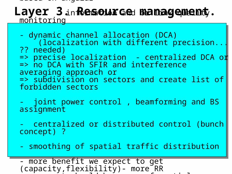
Layer 3. Resource management.- new functions: physical channel allocation based on angular information and or link quality monitoring
- dynamic channel allocation (DCA) (localization with different precision... ?? needed)=> precise localization - centralized DCA or => no DCA with SFIR and interference averaging approach or=> subdivision on sectors and create list of forbidden sectors
- joint power control , beamforming and BS assignment
- centralized or distributed control (bunch concept) ?
- smoothing of spatial traffic distribution
- more benefit we expect to get (capacity,flexibility)- more RR management should be aware of spatial characteristics
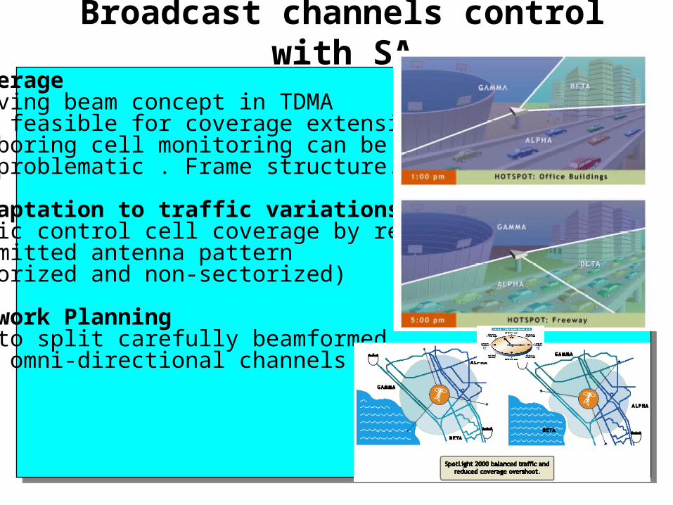
Broadcast channels control with SA- Coverage revolving beam concept in TDMA(more feasible for coverage extension)neighboring cell monitoring can bemore problematic . Frame structure...
- Adaptation to traffic variationsTraffic control cell coverage by reshapingtransmitted antenna pattern (sectorized and non-sectorized)
- Network Planning need to split carefully beamformed and omni-directional channels …..
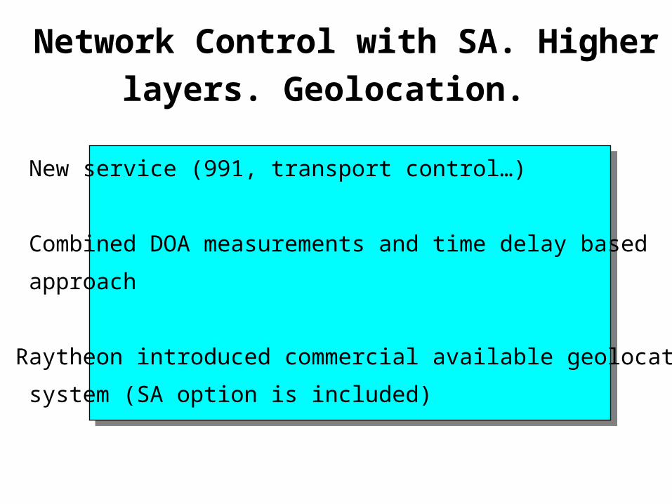
Network Control with SA. Higher layers.
Geolocation.
New service (991, transport control…)
Combined DOA measurements and time delay based
approach
Raytheon introduced commercial available geolocation
system (SA option is included)
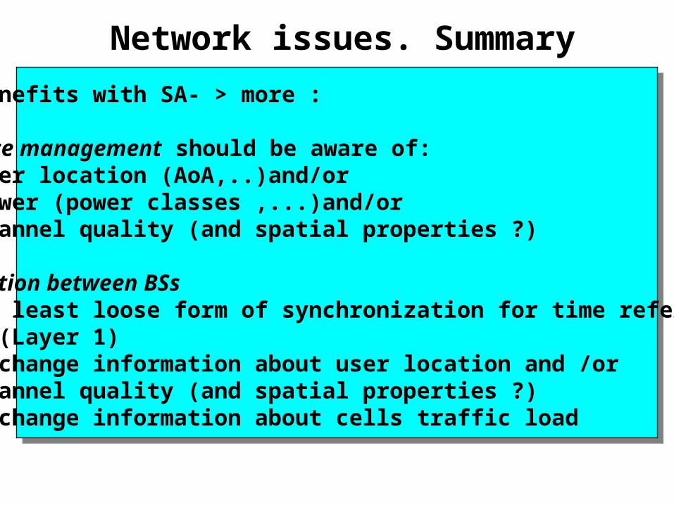
Network issues. Summary
- More benefits with SA- > more :
Resource management should be aware of: - > User location (AoA,..)and/or - > Power (power classes ,...)and/or - > Channel quality (and spatial properties ?) Co-ordination between BSs -> at least loose form of synchronization for time reference BF (Layer 1) -> exchange information about user location and /or - > channel quality (and spatial properties ?) -> exchange information about cells traffic load
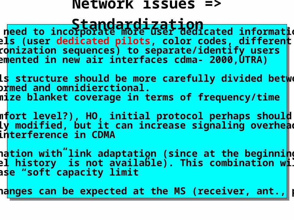
Network issues => Standardization - It is need to incorporate more user dedicated information into channels (user dedicated pilots, color codes, different synchronization sequences) to separate/identify users (implemented in new air interfaces cdma- 2000,UTRA)
- Channels structure should be more carefully divided between beamformed and omnidierctional. Minimize blanket coverage in terms of frequency/time
- DTX(comfort level?), HO, initial protocol perhaps should be slightly modified, but it can increase signaling overhead=> more interference in CDMA
- combination with link adaptation (since at the beginning “channel history” is not available). This combination will increase “soft capacity limit”
- some changes can be expected at the MS (receiver, ant., protocols)
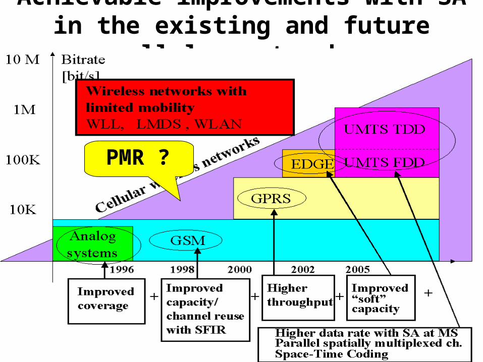
Achievable improvements with SA in the existing and future cellular networks.
PMR ?
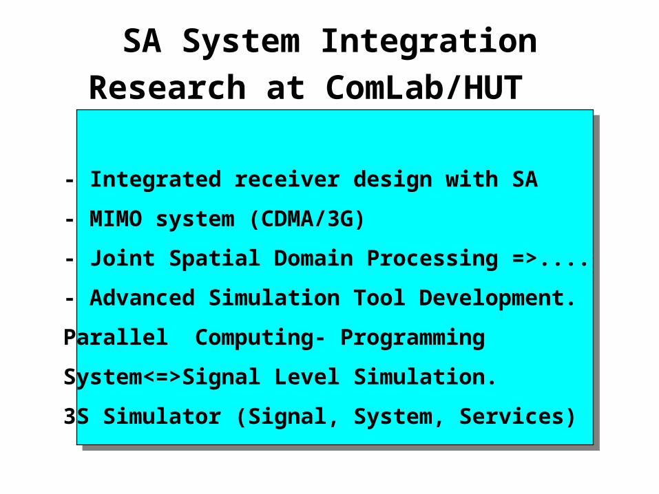
SA System Integration Research at
ComLab/HUT
- Integrated receiver design with SA
- MIMO system (CDMA/3G)
- Joint Spatial Domain Processing =>....
- Advanced Simulation Tool Development.
Parallel Computing- Programming
System<=>Signal Level Simulation.
3S Simulator (Signal, System, Services)
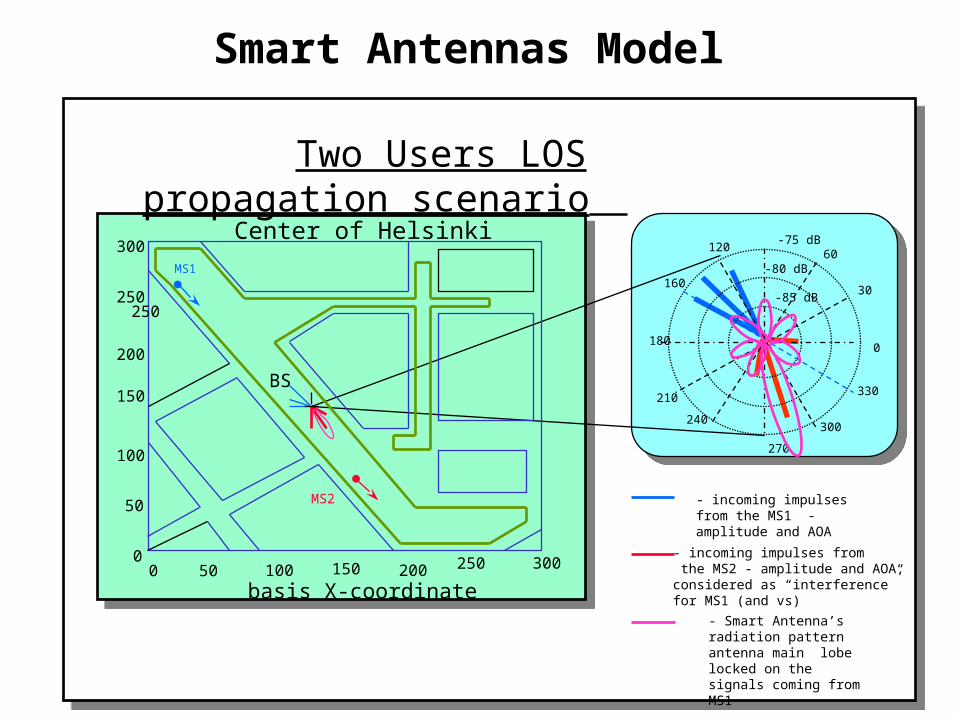
MS2
Two Users LOS propagation scenario
Center of Helsinki
BS
MS1
0180
-75 dB
-85 dB
-80 dB
30
60120
160
210
240
270
300
330
- incoming impulses from the MS1 - amplitude and AOA
- Smart Antenna’s radiation pattern antenna main lobe locked on the signals coming from MS1
- incoming impulses from the MS2 - amplitude and AOA,considered as “interference”for MS1 (and vs)
300
250
200
150
250
100
50
00 50 100 150 200 250 300
basis X-coordinate
Smart Antennas Model
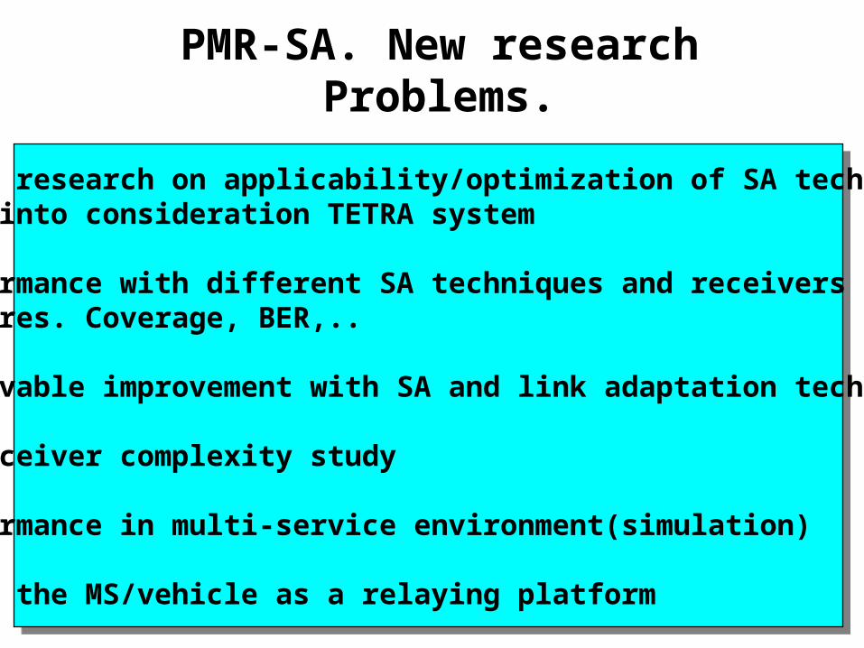
PMR-SA. New research Problems.
- Basic research on applicability/optimization of SA techniquestaking into consideration TETRA system - Performance with different SA techniques and receiversstructures. Coverage, BER,..
- Achievable improvement with SA and link adaptation techniques
- Transceiver complexity study
- Performance in multi-service environment(simulation)
- SA at the MS/vehicle as a relaying platform
Publications1.Edward Mutafungwa, Lauri Halme, Viktor Nässi, Adrian Boukalov “A study of the Järvenpää-Lahti motorway's IT link alternatives for the connection of control stations”, Espoo, Otaniemi: TKK Tietoliikennelaboratorio technology reports, 1998.
2. Adrian Boukalov "The impact of a non-uniform spatial traffic distribution on the CDMA cellular networks system parameters", URSI/Remote Sensing Club of Finland/IEEE XXIII Convention on Radio Science and Remote Sensing Symposium, Otaniemi 24-25 August, 1998, Helsinki University of Technology Laboratory of Space tech. Report 35, p.29-30
3. Boukalov Adrian, Sven-Gustav Häggman and Antti Pietilä "The Impact of a Non-uniform Spatial Traffic Distribution onthe CDMA Cellular Network System Parameters", ICPWC'99, Jaipur, India, February 1999, pp. 394 -398.
4. Boukalov Adrian, Sven-Gustav Häggman "UMTS Radio Network Simulation with Smart Antennas ", Proceedings of the Virginia Tech Symposium on Wireless Personal Communications, June 2-4, 1999, Blacksburg , USA , pp. 95-102.
5. Boukalov Adrian, "System Aspects of Smart Antennas Technology" Presentation at Radio Communication SystemsDepartment / School of Electrical Engineering and Information Technology (EIT) at the Royal Institute of Technology (KTH),Stockholm, Sweden. Available at: http://www.s3.kth.se/radio/seminars/sa.pdf.
6. Boukalov Adrian, Sven-Gustav Häggman "An overview. System aspects of Smart Antennas Technology in WirelessCommunications" (Invited) , Proceedings of the 11th International Conference on Wireless Communications vol. 2, 12-14 July 1999 Calgary , Canada, pp.1-14.
7.Boukalov Adrian, Sven-Gustav Häggman " UMTS Radio Network Simulation with Smart Antennas" to be published inbook Wireless Personal Communications, Kluwer Academic Publishers, 2000. 8. Boukalov Adrian, Sven-Gustav Häggman "System Aspects of Smart Antennas Technology in Cellular WirelessCommunications " (Invited) IEEE Radio and Wireless Conference (RAWCON 99), Denver, Colorado, USA, August 1-4, 1999, pp. 17-22.
9.Boukalov Adrian, "Introduction to Smart Antennas Techniques and Algorithms" Workshop on Smart AntennasTechnology and Applications at RAWCON 99, 1st August 1999.
10. Boukalov Adrian, Sven-Gustav Häggman “ System Aspects of Smart Antennas Technology in WirelessCommunications” to appear in Journal IEEE Transaction in Microwave Theory and Techniques
11. Boukalov Adrian, “Integration of Smart Antennas into Wireless Network” (Invited paper), book Global WirelessCommunications for World. Markets Research Centre's Business Briefing Series. Wireless Technology 2000.
12. (also see at http://www.comlab.hut.fi/thesispub.htm)