Embed Size (px)
Citation preview
page
1: c
onte
nts
Construction Details
Valley 2Loose Hip 2Hip End - Standard 3Hip End - Multiple Girders 4Barn Hip 5Part/Bonnet Hip 5Hip Corner 6Scissors 8Raised Tie 8Dog Leg Intersection 9
Trimming Details
Room in the Roof - Roof Light 10Room in the Roof - Staircase 10Chimney & Trap Hatch 11
Gable Details
Gable Wall Restraint 12Party Wall Restraint 13Gable Ladders 13
Bracing DetailsTypes 14Raised Tie 15Room in the Roof 16British Standard Duo Pitch 17British Standard Mono Pitch 18
Water Tank Details
Support Detail 19
Glossary of Terms 20
page
1: c
onte
nts
page
1: c
onte
nts
Standard Technical DetailsStandard Technical DetailsStandard Technical Details
page
2pa
ge 2
page
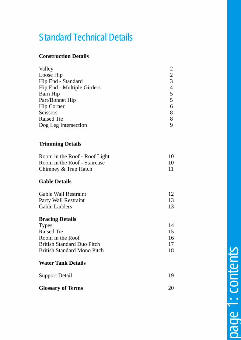
2Valley Construction Valley Construction Valley Construction The construction of valleys using prefabricated reducing valley trusses allows the formation of roof intersections with minimum of site-cut infill. The valley trusses are aligned and the topmost braced back to the supporting trusses; diagonal bracing is then fixed and a longitudinal tie at the apex node. Ideally, the lower edge of the bottom chord of the valley frames is bevelled to suit the roof slope of the supporting trusses or fixing thrust battens cut from one piece of timber for economy.
Sarking, tiling battens and tiling can then be carried out to line in with the supporting roof.
For spans up to 5.7m overall plates a completely loose timber infill can be supported by a girder truss positioned at half the span from the end wall.
Thrust battens are fixed to the truss rafters to prevent the valley frames from sliding
Loose Hip Construction Loose Hip Construction Loose Hip Construction
End mono truss
Girder truss
Hip rafter
page
3pa
ge 3
page
3
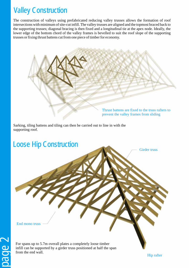
Hip rafterbirdsmouthedover wallplate
Jack rafter
Hip girder
Hip End Construction - StandardHip End Construction - StandardHip End Construction - Standard
TW960 Standard truss clip
( wallplate omitted )
prd
r
Hi gie
t
s
Intermedia e tru
sse
Hi fte
r
p ra
Side jac
rs
k rafte
no-ptch trus
Mo
i
ses
d
k
En jac
rafters
ue
Std trss
s
( Hip rafter birdsmouthed over girder top chord )
Hipboard/Haunch
The design has evolved to reduce traditional Alternatively, the extension rafters may be infill at hipped ends to a minimum - thereby omitted to allow for site fixing of loose, pre-cut keeping site material and labour costs down. jack rafters.
The main structural components consist of a Alpine TW962 shoes are multi-ply hip girder which supports the mono r e c o m m e n d e d f o r pitch trusses and hip rafters forming the hip. supporting the mono
pitch trusses on the Single hip girders are then used to infill up to the hip girder truss.first full truss at the end of the ridge, generally at the same spacing as the full trusses for economic use of components. The mono-pitch trusses and the single hip girder trusses may be supplied with extended rafters for site fixing to the hip rafter.
TW962 Truss shoe supporting monos & loose ceilings joists ( all nail holes used with 3.75 x 30mm square twisted nails )
m
e
Priary hip
girdr
Sec nary h
girder
od
ip
Hipfte
r ra
i e
r
S d Jack ra
ftes
Mono-pitch trusses
S d rus
t . tsse
page
4pa
ge 4
page
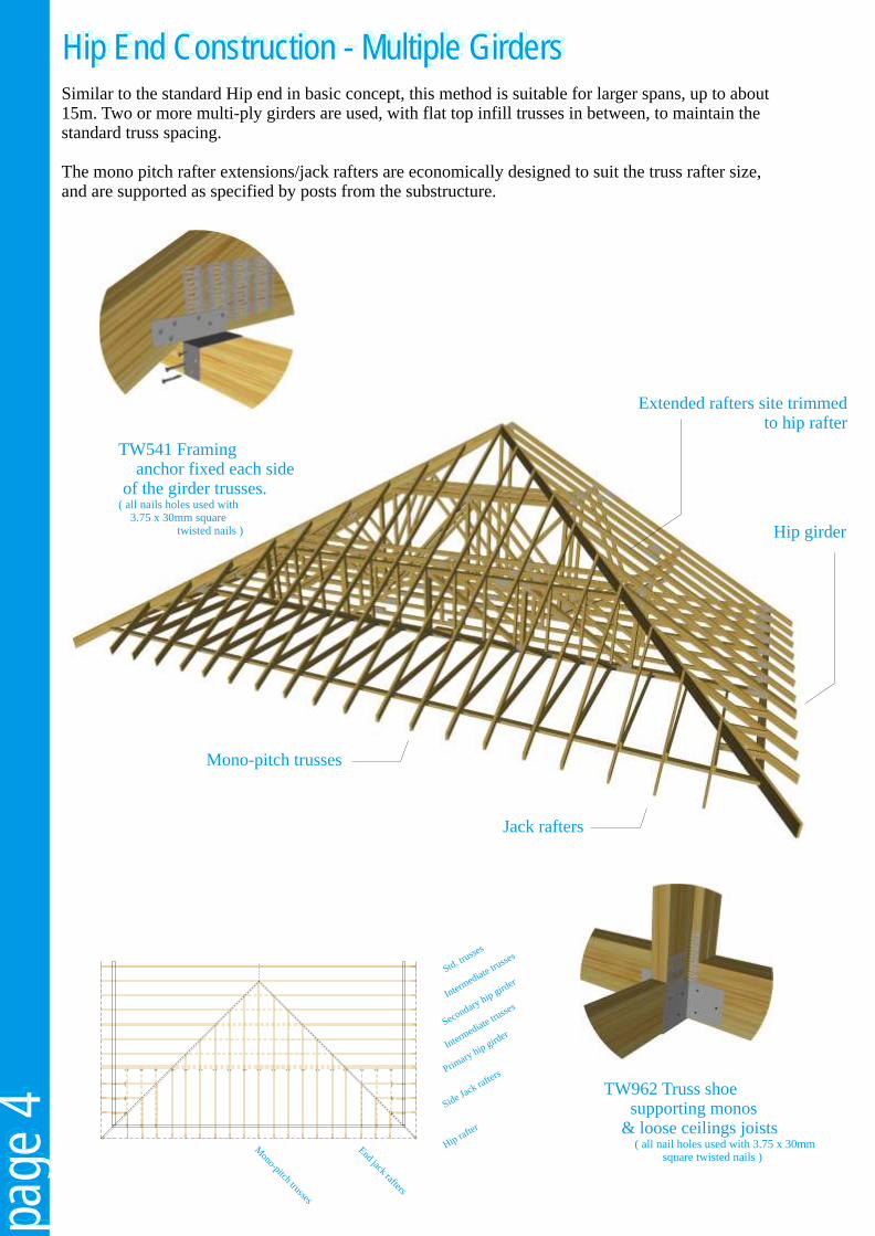
4Hip End Construction - Multiple GirdersHip End Construction - Multiple GirdersHip End Construction - Multiple GirdersSimilar to the standard Hip end in basic concept, this method is suitable for larger spans, up to about 15m. Two or more multi-ply girders are used, with flat top infill trusses in between, to maintain the standard truss spacing.
The mono pitch rafter extensions/jack rafters are economically designed to suit the truss rafter size, and are supported as specified by posts from the substructure.
Hip girder
Extended rafters site trimmed to hip rafter
Jack rafters
Mono-pitch trusses
TW962 Truss shoe supporting monos & loose ceilings joists ( all nail holes used with 3.75 x 30mm square twisted nails )
TW541 Framing anchor fixed each side of the girder trusses.( all nails holes used with 3.75 x 30mm square twisted nails )
te i te
sses
Inerm
d atru
t
s
Intermedia e tru
sse
d
k
En jac
rafters
page
5pa
ge 5
page
5
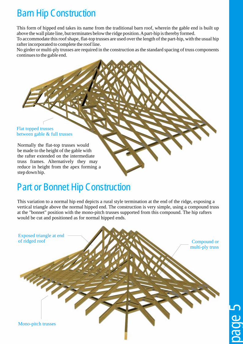
Barn Hip Construction Barn Hip Construction Barn Hip Construction
Part or Bonnet Hip Construction Part or Bonnet Hip Construction Part or Bonnet Hip Construction
This form of hipped end takes its name from the traditional barn roof, wherein the gable end is built up above the wall plate line, but terminates below the ridge position. A part-hip is thereby formed.To accommodate this roof shape, flat-top trusses are used over the length of the part-hip, with the usual hip rafter incorporated to complete the roof line.No girder or multi-ply trusses are required in the construction as the standard spacing of truss components continues to the gable end.
This variation to a normal hip end depicts a rural style termination at the end of the ridge, exposing a vertical triangle above the normal hipped end. The construction is very simple, using a compound truss at the "bonnet" position with the mono-pitch trusses supported from this compound. The hip rafters would be cut and positioned as for normal hipped ends.
Normally the flat-top trusses would be made to the height of the gable with the rafter extended on the intermediate truss frames. Alternatively they may reduce in height from the apex forming a step down hip.
Flat topped trusses between gable & full trusses
Mono-pitch trusses
Exposed triangle at endof ridged roof Compound or
multi-ply truss
page
6pa
ge 6
page
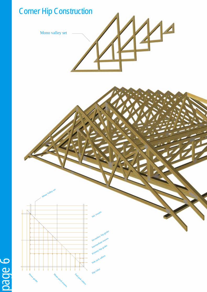
6Corner Hip ConstructionCorner Hip ConstructionCorner Hip Construction
Mono-pitch trusses
End jack rafters
How
e girder
M
Vono alley se
t
en
ry hgi
er
S co daip
rd
Primary hip
girder
Hipfte
r ra
ide j
r
S ack ra
ftes
S d. russes
tt
e
t
Intmedia
ruses
r
tes
Mono valley set
page
7pa
ge 7
page
7
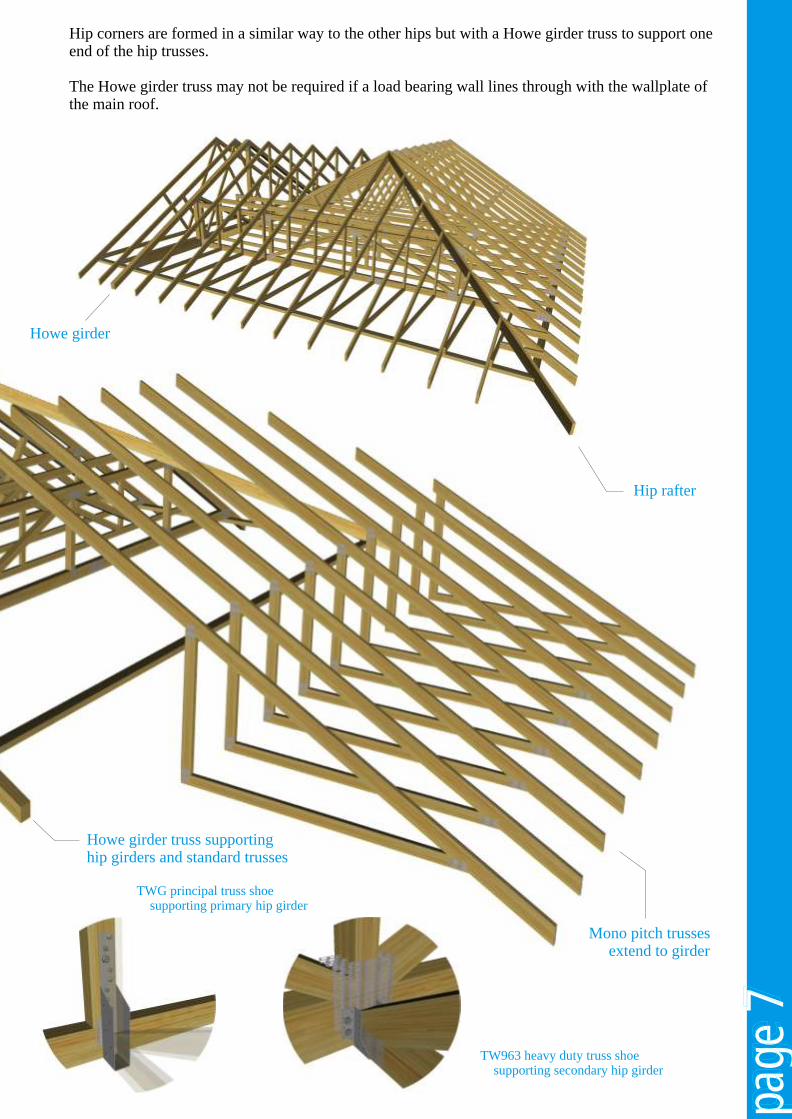
Hip corners are formed in a similar way to the other hips but with a Howe girder truss to support one end of the hip trusses.
The Howe girder truss may not be required if a load bearing wall lines through with the wallplate of the main roof.
Hip rafter
Howe girder
Mono pitch trusses extend to girder
TWG principal truss shoe supporting primary hip girder
TW963 heavy duty truss shoe supporting secondary hip girder
Howe girder truss supportinghip girders and standard trusses

TW964 Glide shoe( all nails holes used with 3.75 x 30mm square twisted nails )
page
8pa
ge 8
page
8Scissors Construction Scissors Construction Scissors Construction
Raised Tie Construction Raised Tie Construction Raised Tie Construction
Due to the elevation of the bottom chord, The use of Alpine glide shoes, which allows some degree of horizontal movement or force reasonable horizontal movement across the will be generated at wallplate levels. walls without imposing horizontal thrust,
assists in accommodating horizontal Research into normal domestic masonry wall deflection.construction has shown that up to 12mm of total deflection can be tolerated by the walls. Our designs are therefore, constrained by this limitation.

page
9pa
ge 9
page
9
Dog Leg IntersectionDog Leg IntersectionDog Leg Intersection
Intersection set outfrom fascia lines
Purlins and binders supported on boltedor nailed ledgers, purlin struts or steel
hangers
Jack rafters and ceiling joists toBuilding Regulations 'Approved Document A'
Purlin supported on ledger which is fixed to face of girder trusses
Binder supported from centre girder in angled hanger

page
10
page
10
page
10
For stairwells, multi-ply trusses or support walls are required each side of the opening and binders are fixed as required to support the floor joists and roof infill. The staircase opening should then be trimmed in the traditional manner.
Purlins
Girder truss
Infill rafters
Staircase trimmers
Trimmers and Purlins
Room in the Roof - Roof LightRoom in the Roof - Roof LightRoom in the Roof - Roof Light
Room in the Roof - Staircase TrimRoom in the Roof - Staircase TrimRoom in the Roof - Staircase Trim
For larger spans and those with intensive trimmed openings, latticed purlin beams are required. These are supported on end and transverse walls and provide maximum floor space.
The rafters and extension ceiling ties are nailed on, to form the flat roof over the dormer window.
Purlins
Roof Light constructionmay be cut on site orprefabricated
Compound or multi-ply Room-in-the-Roof truss
For normal roof spans, up to around 9m and larger spans with internal load bearing walls the truss members can be economically designed to carry domestic loading. For typical dormer windows, traditional purlins supported on multi-ply trusses carry the intermediate infilling over the dormer.
Ledger

B BS SC up to2 x S
page
11
page
11
page
11
Small chimneys and hatches may be
accommodated within the standard truss spacing.
Progressive details are used to accommodate chimney and hatches up
to twice the standard truss spacing.
Trusses must beat least 40mmclear of the stack
B must be not more than 2S - C where S is the standard spacing.
Purlin
Structural post
Binder
Trap hatch detail
Rafters/Webs omitted for clarity.
Chimney & Trap Hatch TrimmingChimney & Trap Hatch TrimmingChimney & Trap Hatch Trimming

page
12
page
12
page
12
Restraining straps must be installed to transmit wind loads on walls into the roof structure, and give stability to the walls.
In the absence of any specific guidance from the building designer, connections should be made with 30 x 5mm thick galvanized steel straps fixed to at least three trusses and noggins with 3.35 x 50mm long galvanized wire nails as shown. On gable walls they should be spaced at not more than 2m centres at rafter and ceiling tie level.
Noggin nailed between trusses
30 x 5mm thick galvanized steel strap
Restraining straps at rafter level
Strap to reach uncut block
Pack between truss and gable wall
Noggin nailed between trusses
30 x 5mm thick galvanized steel strap
Restraining straps at ceiling joist level
Gable Wall Restraining StrapsGable Wall Restraining StrapsGable Wall Restraining Straps

page
13
page
13
page
13
Party Wall Restraining StrapsParty Wall Restraining StrapsParty Wall Restraining Straps
Gable LaddersGable LaddersGable Ladders
Restraining straps must be installed to transmit longitudinal bracing forces along the roof structure and to give stability to the walls. In the absence of any specific guidance from the building designer, connections should be made with 30 x 5mm thick galvanized steel straps fixed to at least three trusses and noggins with 3.35 x 50mm long galvanized wire nails as shown. Party walls should have restraining straps at ceiling tie levels spaced at not more than 2m centres, with the strap connected to three or more trusses on each side of the wall. Straps may also be required at rafter level to transmit longitudinal bracing forces.
Party walls should be stopped 25mm below the tops of rafters. Layers of non-combustible compressible fill such as 50mm mineral wool should be placed above party wall to provide a fire stop.
If the tiling battens are required to be discontinued over a party wall, then lateral restraint must be provided in addition to that required to transfer longitudinal bracing forces. This should consist of straps (or equivalent) adequately protected against corrosion, with a minimum cross sectional area of 50sq. mm. These straps should be spaced at not more than 1.5m centres, and be fixed to three rafter members and noggins on each side of the party wall by 3.35mm diameter galvanized nails with a minimum penetration into the timber of 32mm.
Should the width exceed the maximum span allowed for the tile battens then internoggins should be built into the ladder. The width should not exceed twice the truss spacing and the last truss should be spaced back from the gable as shown above (section).In cases of large width and in areas of high wind speeds, the building designer should consider the effect of wind loading on the gable overhang which could require holding down straps to prevent uplift.
Gable ladders to be fixed to last truss with nails at 400mm centres
Barge boards & soffits are nailed directly onto the gable ladder
width
Last truss
Internogginwhere required
page
14
page
14
page
14
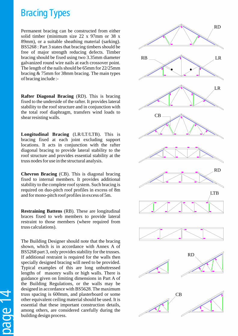
Bracing TypesBracing TypesBracing Types
The Building Designer should note that the bracing shown, which is in accordance with Annex A of BS5268 part 3, only provides stability for the trusses. If additional restraint is required for the walls then specially designed bracing will need to be provided. Typical examples of this are long unbuttressed lengths of masonry walls or high walls. There is guidance given on limiting dimensions in Part A of the Building Regulations, or the walls may be designed in accordance with BS5628. The maximum truss spacing is 600mm, and plasterboard or some other equivalent ceiling material should be used. It is essential that these important construction details, among others, are considered carefully during the building design process.
Restraining Battens (RB). These are longitudinal braces fixed to web members to provide lateral restraint to those members (where required from truss calculations).
Chevron Bracing (CB). This is diagonal bracing fixed to internal members. It provides additional stability to the complete roof system. Such bracing is required on duo-pitch roof profiles in excess of 8m and for mono-pitch roof profiles in excess of 5m.
Longitudinal Bracing (LR/LT/LTB). This is bracing fixed at each joint excluding support locations. It acts in conjunction with the rafter diagonal bracing to provide lateral stability to the roof structure and provides essential stability at the truss nodes for use in the structural analysis.
Rafter Diagonal Bracing (RD). This is bracing fixed to the underside of the rafter. It provides lateral stability to the roof structure and in conjunction with the total roof diaphragm, transfers wind loads to shear resisting walls.
Permanent bracing can be constructed from either solid timber (minimum size 22 x 97mm or 38 x 89mm), or a suitable sheathing material (sarking). BS5268 : Part 3 states that bracing timbers should be free of major strength reducing defects. Timber bracing should be fixed using two 3.35mm diameter galvanized round wire nails at each crossover point. The length of the nails should be 65mm for 22/25mm bracing & 75mm for 38mm bracing. The main types of bracing include :-
RD
RD
LTB
LR
LRRB
RD
CB
CB

page
15
page
15
page
15
Raised Tie BracingRaised Tie BracingRaised Tie Bracing
Rafter diagonal bracing
Chevron bracing
Rafter diagonal bracing
Longitudinal bracingmembers to abut tightlyevery gable & party wall
Section A - A
Section B - BDetail where timber brace isused under rafter extension
Gable end
A A
Plasterboard
Rafter bracing mustextend to wallplate
B
B
Truss
Rafter brace
PlasterboardBattens are to be provided at slopingceiling positions to clear rafter bracing
Permanent stability bracing should be installed in accordance with the design drawings.
Rafter diagonal bracing should extend to contact the wallplate. This may be timber or suitable rigid sarking.
Where the design drawings show either plywood bracing or rigid sarking to the upper surface of the rafters, ensure that it is fixed as specified.
In all roofs using raised tie trusses, fix plasterboard, sheathing or an equivalent diaphragm to the ceiling tie and extended rafters.
Multiple trussesat opening
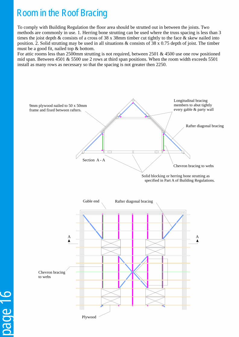
To comply with Building Regulation the floor area should be strutted out in between the joists. Two methods are commonly in use. 1. Herring bone strutting can be used where the truss spacing is less than 3 times the joist depth & consists of a cross of 38 x 38mm timber cut tightly to the face & skew nailed into position. 2. Solid strutting may be used in all situations & consists of 38 x 0.75 depth of joist. The timber must be a good fit, nailed top & bottom.For attic rooms less than 2500mm strutting is not required, between 2501 & 4500 use one row positioned mid span. Between 4501 & 5500 use 2 rows at third span positions. When the room width exceeds 5501 install as many rows as necessary so that the spacing is not greater then 2250.
page
16
page
16
page
16
Rafter diagonal bracing
Chevron bracing to webs
Gable end
Plywood
A A
Room in the Roof BracingRoom in the Roof BracingRoom in the Roof Bracing
Rafter diagonal bracing
Longitudinal bracingmembers to abut tightlyevery gable & party wall
Chevron bracing to webs
Section A - A
Solid blocking or herring bone strutting as specified in Part A of Building Regulations.
9mm plywood nailed to 50 x 50mm frame and fixed between rafters.
page
17
page
17
page
17
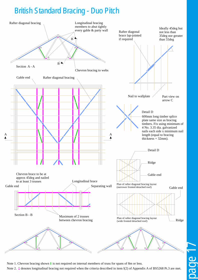
British Standard Bracing - Duo PitchBritish Standard Bracing - Duo PitchBritish Standard Bracing - Duo Pitch
Rafter diagonal bracing
Rafter diagonal bracing
Longitudinal bracingmembers to abut tightlyevery gable & party wall
Chevron bracing to websSection A - A
Gable end
Rafter diagonalbrace lap-jointedif required
Ideally 45deg butnot less than35deg nor greaterthan 55deg
Nail to wallplate
600mm long timber splice plate same size as bracing timbers. Fix using minimum of 4 No. 3.35 dia. galvanized nails each side x minimum nail length (equal to bracing thickness + 32mm).
Chevron brace to be atapprox 45deg and nailedto at least 3 trusses
Gable end
Longitudinal brace
Separating wall
Maximum of 2 trussesbetween chevron bracing
Note 1. Chevron bracing shown is not required on internal members of truss for spans of 8m or less.
Note 2. denotes longitudinal bracing not required when the criteria described in item l(2) of Appendix A of BS5268 Pt.3 are met.
Detail D
Detail D
Ridge
Ridge
Gable end
Gable end
Plan of rafter diagonal bracing layout(wide fronted detached roof)
Plan of rafter diagonal bracing layout(narrower fronted detached roof)
Section B - B
Part view onarrow C
B
B
AA
page
18
page
18
page
18
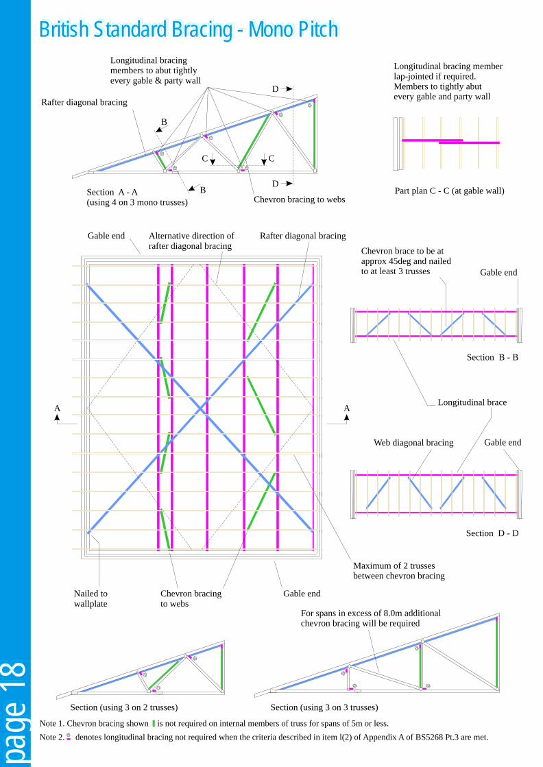
British Standard Bracing - Mono PitchBritish Standard Bracing - Mono PitchBritish Standard Bracing - Mono Pitch
Rafter diagonal bracing
Rafter diagonal bracing
Longitudinal bracingmembers to abut tightlyevery gable & party wall
Chevron bracing to websSection A - A(using 4 on 3 mono trusses)
Section B - B
Section D - D
Gable end
A A
Chevron brace to be atapprox 45deg and nailedto at least 3 trusses
Gable end
Gable end
Gable end
Longitudinal brace
Maximum of 2 trussesbetween chevron bracing
Web diagonal bracing
Nailed towallplate
Chevron bracingto webs
Longitudinal bracing memberlap-jointed if required.Members to tightly abutevery gable and party wall
B
B
C C
D
D
Part plan C - C (at gable wall)
For spans in excess of 8.0m additionalchevron bracing will be required
Section (using 3 on 2 trusses) Section (using 3 on 3 trusses)
Note 1. Chevron bracing shown is not required on internal members of truss for spans of 5m or less.
Note 2. denotes longitudinal bracing not required when the criteria described in item l(2) of Appendix A of BS5268 Pt.3 are met.
Alternative direction ofrafter diagonal bracing
page
19
page
19
page
19
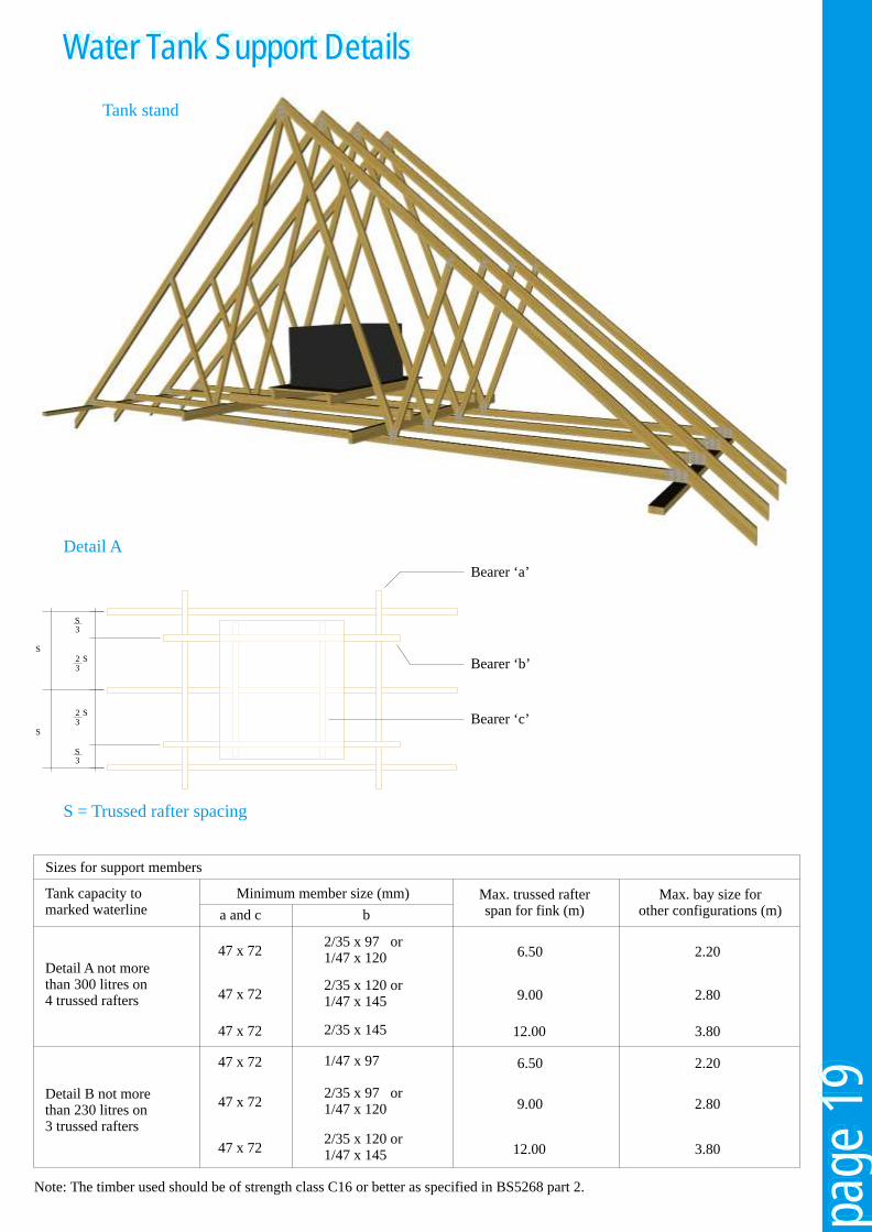
Water Tank Support DetailsWater Tank Support DetailsWater Tank Support Details
Tank capacity tomarked waterline
Detail A not morethan 300 litres on4 trussed rafters
Detail B not morethan 230 litres on3 trussed rafters
Minimum member size (mm)
a and c b
47 x 72
47 x 72
47 x 72
47 x 72
47 x 72
47 x 72
2/35 x 97 or1/47 x 120
1/47 x 97
2/35 x 120 or1/47 x 145
2/35 x 97 or1/47 x 120
2/35 x 145
2/35 x 120 or1/47 x 145
Max. trussed rafterspan for fink (m)
Max. bay size forother configurations (m)
6.50
9.00
12.00
6.50
9.00
12.00
2.20
2.20
2.80
2.80
3.80
3.80
Sizes for support members
Note: The timber used should be of strength class C16 or better as specified in BS5268 part 2.
Bearer ‘a’
Bearer ‘b’
Bearer ‘c’
page
19
page
19
page
19
Water Tank Support DetailsWater Tank Support DetailsWater Tank Support Details
Tank capacity tomarked waterline
Detail A not morethan 300 litres on4 trussed rafters
Detail B not morethan 230 litres on3 trussed rafters
Minimum member size (mm)
a and c b
47 x 72
47 x 72
47 x 72
47 x 72
47 x 72
47 x 72
2/35 x 97 or1/47 x 120
1/47 x 97
2/35 x 120 or1/47 x 145
2/35 x 97 or1/47 x 120
2/35 x 145
2/35 x 120 or1/47 x 145
Max. trussed rafterspan for fink (m)
Max. bay size forother configurations (m)
6.50
9.00
12.00
6.50
9.00
12.00
2.20
2.20
2.80
2.80
3.80
3.80
Sizes for support members
Note: The timber used should be of strength class C16 or better as specified in BS5268 part 2.
Bearer ‘a’
Bearer ‘b’
Bearer ‘c’
S3
S
S
S3
S23
S23
S = Trussed rafter spacing
Tank stand
Detail A

Apex/Peak Duo/dual pitch trussThe uppermost point of a truss. A truss with two rafters meeting at the APEX but not
necessarily having the same PITCH on both sides.Attic truss/room-in-the-roof.A truss which forms the top storey of a dwelling but allows Eavesthe area to be habitable by leaving it free of internal WEB The line where the rafter meets the wall.members. This will be compensated by larger timber sizes elsewhere. Extended Rafter.
See RAISED TIE TRUSS.BargeboardBoard fitted to conceal roof timbers at GABLE END. Fascia
Horizontal board fitted along the length of the building to the Battens edge of the truss overhangs.Small timber members spanning over trusses to support tiles, slates etc. Fink Truss
The most common type of truss used for dwellings. It is duo-Bearer pitch, the rafter having the same pitch. The webs form a letter A member designed to distribute loads over a number of W.trusses.
Gable EndBearing The end wall which is parallel to the trusses and which The part of a truss receiving structural support. This is extends upwards vertically to the rafters.usually a WALLPLATE but can be an internal wall etc. Hip End
An alternative to a GABLE END where the end wall finishes Binder at the same height as the adjacent walls. The roof inclines A longitudinal member nailed to trusses to restrain and from the end wall, usually (but not always) at the same maintain correct spacing. PITCH as the main trusses.
Birdsmouth Hip SetA notch in the underside of a RAFTER to allow a horizontal The trusses, girders and loose timbers required to form a hip seating at the point of support (usually used with RAISED end.TIE TRUSSES).
Horn/nibBlocking An extension of the ceiling tie of a truss (usually monos or Short timbers fixed between chords to laterally rstrain them. bobtailed trusses) which is built into They should be at least 70% of the depth of the CHORDS. Imposed Load
The load produced by occupancy and use including storage, Bottom chord/Ceiling Tie inhabitants, moveable partitions and snow but not wind. Can The lowest member of a truss, usually horizontal which be long, medium or short term.carries the ceiling construction, storage loads and water tank. Internal Member
See WEB.BracingThis can be Temporary, Stability or Wind Bracing which are Intersectiondescribed under these headings. The area where roofs meet.
Building Designer Jack RafterThe person responsible for the structural stability and An infill rafter completing the roof surface in areas such as integrity of the building as a whole. corners of HIP ENDS or around chimneys.
Cantilever Live LoadThe part of a structural member of TRUSS which extends Term sometimes used for IMPOSED LOADS.beyond its bearing.
Longitudinal Bracing.Chevron Bracing Component of STABILITY BRACING.Diagonal bracing nailed to the truss in the plane of the specified webs to add stability. Loose Timber
Timbers not part of a truss but added to form the roof in areas Dead Load where trusses cannot be used.The load produced by the fabric of the building, always long term (see DESIGN LOADS). Mono-pitch truss.
A truss in the form of a right-angled triangle with a single Deflection rafter.The deformation caused by the loads
NailplateDesign Loads Metal PLATE having integral teeth punched from the plate The loads for which the unit is designed. These consider the material. It is used for joining timber in one plane with no duration of the loads long term, medium term, short term and overlap. It will have an accreditation certificate and will be very short term. manufactured, usually, from galvanised steel. It is also
available in stainless steel.
page
20:
glo
ssar
y of
term
spa
ge 2
0: g
loss
ary
of te
rms
page
20:
glo
ssar
y of
term
s
Node SplicePoint on a truss where the members intersect. A joint between two members in line using a NAILPLATE or
glued finger joint.NoggingsTimber pieces fitted at right angles between the rafters and Strapceiling ties to form fixing points. Metal component designed to fix trusses and wallplates to
walls.OverhangThe extension of a rafter or ceiling tie of a truss beyond its Strutsupport or bearing Internal member connecting the third point and the quarter . point on a FINK TRUSSS.Part ProfileA truss type formed by truncating a normal triangular Stub Endtruss. See PART PROFILE.
Pitch Temporary BracingThe angle of the rafter to the horizontal, measured in An arrangement of diagonal loose timbers installed for safety degrees. during erection. Often incorporated with permanent
STABILITY and WIND BRACING structures.PurlinsTimber members spanning over trusses to support cladding or Timber Stress Gradingbetween trusses to support loose timbers. The classification of timber into different structural qualities
based on strength (see BS4978: 1996).QueenInternal member (WEB) which connects the APEX to a third Trimmerpoint on a FINK TRUSS. A piece of timber used to frame around openings.
Rafter/Top chord Trussed Rafter DesignerThe uppermost member of a truss which normally carries the The person responsible for the design of the TRUSSED roof covering. RAFTER as a component and for specifying the points where
Bracing is required.Rafter Diagonal BracingComponent of STABILITY BRACING. Truss clip
A metal component designed to provide a safe structural Raised Tie Truss connection of trusses to wallplates. Also to resist wind uplift A truss which is supported at a point on the rafter which is and to remove the damage caused by SKEW beyond the point where the rafter meets the ceiling NAILING.tie.
Truss ShoeReturn Span A metal component designed to provide a structural The span of a truss being supported by a girder. connection and support for a truss to a girder or
beam.RidgeThe line formed by the truss apexes. Uniformly distributed load (UDL)
A load that is uniformly spread over the full length of the Roof Designer member.The person responsible for the roof structure as a whole and who takes into account its stability and capability of Valley Boardtransmitting wind forces on the roof to suitable load-bearing A member raking from incoming RIDGE to corner in a valley walls. construction.
Scab Valley Frames/SetAdditional timber fitted to the side of a truss to effect a local Infill frames used to continue the roofline when roofs reinforcement, particularly in RAISED TIE intersect.TRUSSES.
VergeSetting out Point The line where the trussed rafters meet the gable The point on a truss where the undersides of the rafter and wall.ceiling tie meet.
WallplateSoffit A timber member laid along the length of the load bearing Board fixed underneath EAVES overhang along the length of walls to support the trusses. the building to conceal timbers.
WebsSpan Timber members that connect the rafters and the ceiling tie Span over wallplates is the distance between the outside together forming triangular patterns which transmit the forces edges of the two supporting wallplates. This is usually the between them.overall length of the ceiling tie.
Wind bracingSpandrel Panel An arrangement of additional timbers or other structural A timber frame, triangular panel forming gable wall above elements in the roof space, specially designed to transmit ceiling line. wind forces to suitable load-bearing walls.
page
21:
glo
ssar
y of
term
spa
ge 2
1: g
loss
ary
of te
rms
page
21:
glo
ssar
y of
term
s