Embed Size (px)
Citation preview

7/22/2019 Standard Training Manual
http://slidepdf.com/reader/full/standard-training-manual 1/286

7/22/2019 Standard Training Manual
http://slidepdf.com/reader/full/standard-training-manual 2/286
12012 Version 17April
Contents
1.0 Introduction ............................................................................................................................. 7
1.1 Background ....................................................................................................................................................................... 9
1.2 Important Notes Regarding This Documentation ............................................................ ............................................... 10
1.3 Overview of the User Interface ........................................................ ................................................................. .............. 11
1.4 Orion Modelling, Analysis & Design Flowchart ......................................................................................................... ...... 12
1.5 Graphic Editor - General Principles ............................................................. .............................................................. ...... 13 1.5.1 Selecting single and / or multiple members ................................................................................................................ 13 1.5.2 Update - Editing a member .......................................................................................................................................... 14 1.5.3 Deletion – Single / Multiple members ......................................................................................................................... 14 1.5.4 Deletion – Selective deletion from a group of members ......................................................... .................................... 15 1.5.5 Object Snapping (Osnaps) ............................................................. ................................................................. .............. 15 1.5.6 Basic View/Zoom functions ........................................................... ................................................................. .............. 16
2.0 Building the Model ................................................................................................................. 17
2.1 Getting Started – Project Parameters & Settings ........................................................................................................... 19 2.1.1 Exercise aims ................................................................................................................................................................ 19 2.1.2 Launching Orion ........................................................................................................................................................... 19 2.1.3 Creating a New Project ................................................................................................................................................ 20 2.1.4 Settings Centre ........................................................ ................................................................. .................................... 20 2.1.5 Drawing Sheet Selection .............................................................................................................................................. 21 2.1.6 Inserting Storey Height ................................................................................................................................................ 22
2.2 Creating Axes .................................................................................................................................................................. 23 2.2.1 Exercise Aims ............................................................................................................................................................... 23 2.2.2 Establishing Axis Directions and Labels ............................................................... ......................................................... 23
2.2.3 Osnap methods ............................................................................................................................................................ 25 2.2.4 Pick methods ........................................................... ................................................................. .................................... 25 2.2.5 Editing Axes ............................................................. ................................................................. .................................... 25 2.2.6 Selecting/Stretching Multiple Axes .......................................................... .............................................................. ...... 27 2.2.7 Creating Axes Individually ............................................................................................................................................ 28
2.3 Creating Columns ....................................................... ................................................................. .................................... 29 2.3.1 Exercise Aims ............................................................................................................................................................... 29 2.3.2 The Properties and Options with Columns .................................................................................................................. 29 2.3.3 Creating Rectangular Columns ............................................................................................................ ......................... 32 2.3.4 Inserting Multiple Columns ................................................................................................................. ......................... 34 2.3.5 Creating Circular Columns ............................................................ ................................................................. .............. 38 2.3.6 Using the Polyline Column Editor ............................................................. .............................................................. ...... 38
2.4 Creating Shear Walls ....................................................................................................................................................... 40 2.4.1 Exercise Aims ............................................................................................................................................................... 40 2.4.2 Overview of Options .................................................................................................................................................... 40 2.4.3 Creating a Core Wall .................................................................................................................................................... 42
2.5 Creating Beams ............................................................................................................................................................... 43 2.5.1 Exercise Aims ............................................................................................................................................................... 43 2.5.2 Creating Multiple Rectangular Beams.......................................................................................................................... 43 2.5.3 Inserting the rest of the 1st Storey Beams ......................................................... .......................................................... 47
2.6 Creating Slabs ................................................................................................................................................................. 49 2.6.1 Exercise Aims ............................................................................................................................................................... 49
2.6.2 Creating 2 Way Spanning Slabs ..................................................................................... ............................................... 49 2.6.3 Setting Slab Types Automatically ................................................................................................................................. 53

7/22/2019 Standard Training Manual
http://slidepdf.com/reader/full/standard-training-manual 3/286
22012 Version 17April
2.6.4 Creating Cantilever Slabs ............................................................................................................................................. 54 2.6.5 Additional Slab Information ......................................................................................................................................... 56
2.7 Member Re-Labelling ..................................................................................................................................................... 57 2.7.1 Exercise Aims ............................................................................................................................................................... 57 2.7.2 Changing the member labels ....................................................................................................................................... 57
2.8 Using Tables to Edit Multiple Members ......................................................................................................................... 58 2.8.1 Exercise Aims ............................................................................................................................................................... 58 2.8.2 Changing Properties of Multiple Members ................................................................................................................. 58 2.8.3 Changing Properties of One Member in the table only ............................................................................................... 59
2.9 Wall Loads and Additional Beam Loads ............................................................. ............................................................. 60 2.9.1 Exercise Aims ............................................................................................................................................................... 60 2.9.2 Apply Beam Wall Loads ................................................................................................................................................ 60 2.9.3 Apply Additional Beam Loads ...................................................................................................................................... 62
2.10 Generating a 3D View of the Model and Creating Additional Storeys ........................................................................... 65 2.10.1 Exercise Aims ............................................................................................................................................................... 65 2.10.2 Generating/Manipulating a 3D View ........................................................................................................................... 65
2.10.3 Inserting Additional Floors ........................................................................................................................................... 67 2.10.4 Copying Floor Data to Other Floors ............................................................................................................................. 68 2.10.5 Moving between Storeys ............................................................................................................................................. 68 2.10.6 Editing the Roof ........................................................................................................................................................... 69 2.10.7 Editing the Storey Height ............................................................................................................................................. 69 2.10.8 Specifying Imposed Load Reductions for Each Floor ................................................................................................... 70
3.0 Analysing the Structure ........................................................................................................... 71
3.1 Pre-Analysis .................................................................................................................................................................... 73 3.1.1 Exercise Aims ............................................................................................................................................................... 73 3.1.2 Pre-Analysis Tab - Parameters, Loading and Materials ............................................................................................... 73 3.1.3 Model Options Tab – Model Analysis Settings ............................................................................................................ 80
3.2 Performing the Analysis .................................................................................................................................................. 82 3.2.1 Checking the notional lateral loads ............................................................................................................................. 84
3.3 Post-Analysis ................................................................................................................................................................... 86 3.3.1 Cross Checking the Analysis Result .............................................................................................................................. 86 3.3.2 Model and Analysis Results Display ............................................................................................................................. 88 3.3.3 Analysis Output Reports (for information only) .......................................................................................................... 92
4.0 Beam Reinforcement .............................................................................................................. 97
4.1 Beam Reinforcement Design .......................................................................................................................................... 99 4.1.1 Exercise Aims ............................................................................................................................................................... 99 4.1.2 Beam Design Settings and Parameters ........................................................................................................................ 99
4.2 Designing all Beams using Batch Mode .......................................................................................................................... 99 4.2.1 Graphical Review of Passing / Failing Members ........................................................................................................ 101
4.3 Interactive Beam Design ............................................................................................................................................... 102 4.3.1 Utilisation Ratios ........................................................................................................................................................ 102 4.3.2 The Axis and Beam Information Editor ...................................................................................................................... 103 4.3.3 The Reinforcement Data Screen ................................................................................................................................ 104 4.3.4 Beam Detail Drawings ................................................................................................................................................ 104 4.3.5 Standard Bar Patterns ................................................................................................................................................ 105 4.3.6 Modifying the Number and Size of Bars .................................................................................................................... 106 4.3.7 Bar Layers ................................................................................................................................................................... 106 4.3.8 Modifying bar curtailment ......................................................................................................................................... 108 4.3.9 Beam Loading and Force Diagrams ................................................................ ............................................................ 108
4.4 Creating the Beam Elevation Drawings ........................................................................................................................ 110

7/22/2019 Standard Training Manual
http://slidepdf.com/reader/full/standard-training-manual 4/286
32012 Version 17April
4.4.1 Putting All Beams onto a Single Sheet Automatically .................................................................................... ............ 110
5.0 Column and Wall Reinforcement........................................................................................... 111
5.1 Column &b Wall Reinforcement Design ....................................................................................................................... 113 5.1.1 Exercise Aims ............................................................................................................................................................. 113 5.1.2 Column Design Settings and Parameters .................................................................................................... ............... 113
5.2 Designing all Columns using Batch Mode ........................................................................ ............................................. 113 5.2.1 Creating a Column Schedule ...................................................................................................................................... 115 5.2.2 Creating a Column Output Report ............................................................................................................................. 116 5.2.3 Creating a Foundation Loads Report.......................................................................................................................... 118
5.3 Interactive Column Design ............................................................... ................................................................. ............ 119 5.3.1 Exercise Aims ............................................................................................................................................................. 119 5.3.2 Understanding the Column Design Editor.................................................................................................................. 119 5.3.3 Designing Rectangular Column .................................................................................................................................. 121 5.3.4 Column Slenderness ........................................................... ................................................................. ....................... 123 5.3.5 Column Interaction Diagrams .................................................................................................................................... 124 5.3.6 Fixing the Bar Layout .......................................................... ................................................................. ....................... 125
5.3.7 Link Arrangement ............................................................... ................................................................. ....................... 126 5.3.8 Shear Design............................................................................................................................................................... 127 5.3.9 Biaxial bending vs. BS 8.1.1.0-Cl 3.8.4.5 design ......................................................................................................... 127
5.4 Designing a Wall............................................................................................................................................................ 128
6.0 Slab Design ........................................................................................................................... 133
6.1 Slab Design and Detailing.............................................................................................................................................. 135 6.1.1 Exercise Aims ............................................................................................................................................................. 135 6.1.2 Slab Design Settings ................................................................................................................................................... 135 6.1.3 Member and Steel Bar Label Templates (Additional Info. Only)................................................................................ 136
6.2 Create Slab Reinforcement Strips ................................................................................................................................. 137
6.2.1 Filtering the Display of Slab Reinforcement (for information only) ........................................................................... 139 6.3 Editing the Bar Layout ....................................................................................................... ............................................. 139
6.4 Creating Slab Output ............................................................. ................................................................. ....................... 141 6.4.1 Output for an Individual Slab Strip ........................................................... .............................................................. .... 141 6.4.2 Creating a Slab Output Report for the Entire Floor.................................................................................................... 141 6.4.3 Table of Quantities ................................................................................................................... .................................. 142
7.0 Flat Slabs .............................................................................................................................. 143
7.1 Flat slabs ....................................................................................................................................................................... 145 7.1.1 Exercise Aims ............................................................................................................................................................. 145
7.2 Creating the Flat Slabs in the Model ............................................................................................................................. 145
7.2.1 Inserting the Slabs .............................................................. ................................................................. ....................... 146 7.3 Creating Slab Loads and Openings .............................................................. ................................................................. . 148 7.3.1 Slab Loads................................................................................................................................................................... 148 7.3.2 Slab Openings .......................................................... ................................................................. .................................. 150
7.4 Creating Additional Storeys .......................................................................................................................................... 151 7.4.1 Storey Information ..................................................................................................................................................... 151
8.0 Building Analysis for Flat Slab ............................................................................................... 153
8.1 Building Analysis for Flat Slabs ......................................................... ................................................................. ............ 155 8.1.1 Exercise Aims ............................................................................................................................................................. 155 8.1.2 Model Options Settings ...................................................... ................................................................. ....................... 155 8.1.3
Pre-Analysis – Building Model Check ................................................................. ........................................................ 156
8.2 Performing the Analysis ................................................................................................................................................ 157
7/22/2019 Standard Training Manual
http://slidepdf.com/reader/full/standard-training-manual 5/286
42012 Version 17April
8.2.1 Building Analysis ........................................................................................................................................................ 157 8.2.2 Checking the notional horizontal forces .................................................................................................................... 158
8.3 Post-Analysis ................................................................................................................................................................. 159 8.3.1 Cross Checking the Analysis Result ............................................................................................................................ 159 8.3.2 Model and Analysis Results Display ........................................................................................................... ................ 160
9.0 Load Chase Down .................................................................................................................. 163
9.1 Gravity Load Chase Down Using FE Analysis ................................................................................................................ 165 9.1.1 Exercise Aims ............................................................................................................................................................. 165 9.1.2 Finite Element Model Generation Options ................................................................................................................ 165
9.2 Generating/Performing the FE Analysis Model ............................................................................................................ 169 9.2.1 Creating the FE mesh for Analysis.............................................................................................................................. 169 9.2.2 Performing the Batch FE Load Chase Down............................................................................................................... 171
9.3 Cross checking the Finite Element Results ................................................................................................................... 175
10.0 Flat Slab ................................................................................................................................ 177
10.1 Designing the Flat Slab ................................................................................................................................................. 179 10.1.1 Exercise Aims ............................................................................................................................................................. 179 10.1.2 Finite Element – Post Processing Settings ................................................................................................................. 179
10.2 Floor Analysis Post Processing ...................................................................................................................................... 180 10.2.1 Deflection Plots .......................................................................................................................................................... 180 10.2.2 Loading and Effects Toolbars ..................................................................................................................................... 181 10.2.3 Loading and Effects ........................................................ ................................................................. ........................... 182 10.2.4 Setting the Concrete Effective Depth ........................................................................................................................ 184 10.2.5 Bottom Steel Reinforcement Provision ..................................................................................................................... 185 10.2.6 Creating the User Defined Contours (bottom steel) ............................................................ ...................................... 186 10.2.7 Creating the User Defined Contours (top steel) ........................................................................................................ 187
10.3 Exporting and Displaying Contours ......................................................... ................................................................. ..... 189
10.4 Exporting to DXF (for information) ............................................................................................................................... 190
10.5 Designing the Columns/Walls ....................................................................................................................................... 191
11.0 Appendix A ........................................................................................................................... 193
11.1 Wind Loads ................................................................................................................................................................... 195 11.1.1 Specifying Wind Combinations .................................................................................................................................. 195 11.1.2 Applying a Single Wind Load to Each Floor ................................................................................................................ 196 11.1.3 Applying Wind Loads directly to Columns & Walls .................................................................................................... 200
12.0 Appendix B ........................................................................................................................... 203
12.1 Beam Design Settings and Detailing ............................................................................................................................. 205
12.1.1 The Design Tab ............................................................... ................................................................. ........................... 205 12.1.2 The Parameters Tab ................................................................................................................................................... 206 12.1.3 The Bar Selection Tab ................................................................................................................................................ 206 12.1.4 The Curtailment Tab .................................................................................................................................................. 208 12.1.5 The Detailing Tab ....................................................................................................................................................... 209 12.1.6 The Layers Tab ........................................................................................................................................................... 210 12.1.7 Manually Creating Drawing Sheets ............................................................................................................................ 210
13.0 Appendix C ........................................................................................................................... 213
13.1 Column Design Settings and Detailing ............................................................... ........................................................... 215 13.1.1 The Design Tab ............................................................... ................................................................. ........................... 215 13.1.2 The Steel Bars Tab ...................................................................................................................................................... 216
13.1.3 The Detail Drawings Tab ............................................................................................................................................ 219 13.1.4 To Rationalise the Steel Bars in Individual Columns .................................................................................................. 221
7/22/2019 Standard Training Manual
http://slidepdf.com/reader/full/standard-training-manual 6/286
52012 Version 17April
13.2 To Rationalise the Steel Bars in Multiple Columns ....................................................................................................... 222
13.3 Creating the Column Detail Drawings ......................................................... .............................................................. .... 223
14.0 Appendix D ........................................................................................................................... 227
14.1 Foundation Design ........................................................................................................................................................ 229
14.1.1 Introduction ............................................................................................................................................................... 229 14.1.2 Foundation Design Settings ....................................................................................................................................... 229 14.1.3 Choice of Loading Method ......................................................................................................................................... 230
14.2 Pad Footings.................................................................................................................................................................. 230 14.2.1 Pad footing design...................................................................................................................................................... 230 14.2.2 Pad Footing Details .................................................................................................................................................... 233
14.3 Strip Footings ................................................................................................................................................................ 235 14.3.1 Strip Footing Design ................................................................................................................................................... 235 14.3.2 Designing the Foundation Beam ................................................................................... ............................................. 238
14.4 Raft Foundation Design ................................................................................................................................................ 240
15.0 Appendix E ........................................................................................................................... 243
15.1 Load Combinations and the Loading Generator ........................................................................................................... 245 15.1.1 The Loading Generator .............................................................................................................................................. 245
16.0 Appendix F ........................................................................................................................... 251
16.1 Report Manager ......................................................... ................................................................. .................................. 253 16.1.1 Concrete and Form Estimation Reports ..................................................................................................................... 253 16.1.2 Report Manager ...................................................... ................................................................. .................................. 254
17.0 Appendix G ........................................................................................................................... 255
17.1 Polyline Column Editor ................................................................................................................................................. 257 17.1.1 Creating an L-shaped column. ................................................................. ............................................................... .... 257
18.0 Appendix H ........................................................................................................................... 261
18.1 Slab Design using FE Analysis ........................................................... ................................................................. ............ 263 18.1.1 Introduction ............................................................................................................................................................... 263 18.1.2 Creating FE Slab Strips ........................................................ ................................................................. ....................... 263 18.1.3 Finite Element Model Generation ............................................................ .............................................................. .... 265 18.1.4 FE Analysis Post Processing ........................................................... ................................................................. ............ 266 18.1.5 Updating the FE Strips with Reinforcement ....................................................... ........................................................ 269
19.0 Appendix I ............................................................................................................................ 271
19.1 Enhancing the General Arrangement Drawings ........................................................................................................... 273 19.1.1 Exercise Aims ............................................................................................................................................................. 273
19.1.2 Dimensioning the Grid Spacing ........................................................................................................... ....................... 273 19.1.3 Dimensioning up the Cantilever Slabs........................................................................................................................ 276 19.1.4 Shrinking Axes and Setting Unused Axes to Ghost .................................................................. .................................. 277 19.1.5 Creating Slab Section Views ............................................................................... ........................................................ 278
20.0 Appendix J ............................................................................................................................ 281
20.1 Orion Data File Structure and Project Settings ............................................................................................................. 283 20.1.1 Project Settings .......................................................................................................................................................... 284

7/22/2019 Standard Training Manual
http://slidepdf.com/reader/full/standard-training-manual 7/286

7/22/2019 Standard Training Manual
http://slidepdf.com/reader/full/standard-training-manual 8/286
7
Introduction
Background
2012 Version 17.0April
1.0 Introduction

7/22/2019 Standard Training Manual
http://slidepdf.com/reader/full/standard-training-manual 9/286

7/22/2019 Standard Training Manual
http://slidepdf.com/reader/full/standard-training-manual 10/286
9
Introduction
Background
2012 Version 17.0April
1.1 BackgroundOrion is developed for the analysis, design and drafting of Concrete Building Stuctures. Unlike general purpose structural
analysis programs, Orion is concentrated on accurate analysis, fast data preparation, automated reinforced concrete design
and automated preparation of engineering drawings and details.Building systems have the following common structural features:
Geometry of a building system generally formed principly by horizontal beams and vertical columns.
Most of the time, the column and beam elements have similar cross-sections so that standard section types can be formed.
The in-plane stiffness of the floor slabs is considered to be high, forming rigid diaphragms at each floor level.
Applied loads are either in vertical (dead and imposed loads) or horizontal (wind, soil pressure or earthquake) directions.
There will often be repetition (in whole or in part) of floor layouts from one level to the next.
General arrangement drawings (GA’s) are somewhat stylised, but given the constrained area of application outlined above,
the system allows the model to be described by the development of GA drawings at each floor level. Even that process is
further simplified since beams etc are dealt with as coherant objects, not just lines. The more simplistic centre line analysis
model is automatically created in background at the same time. For example, in reality, 300 wide beams and 400 square
columns along an external elevation may be arranged with the outside faces flush which would mean that their true centre
lines are not aligned. It would be common practice to ignore this degree of mis-alignment for analysis purposes. Orion will
not un-necessarily complicate the analysis model.
In addition – different preferences can be held and automatically used for analysis and design purposes. For example, beam
flanges can be ignored in the analysis but then utilised for reinforcement design (sagging moments only) without any re-
modelling.
In summary, an Orion model allows you to
Create GA drawings
Design the Floor Slabs, and de-compose floor loads onto beams.
Analyse the building frame
Design continuous beams, columns. walls, and foundations (pad, strip and raft)
Automatically generate RC detail drawings.
Note that analysis and design results are represented so that the reports look like a "Building Output" by classifying the
members as columns, walls, slabs and beams with the same notations used in the floor plans.

7/22/2019 Standard Training Manual
http://slidepdf.com/reader/full/standard-training-manual 11/286
10
Introduction
Important Notes Regarding This Documentation
2012 Version 17.0April
1.2 Important Notes Regarding This Documentation
This document is primarily intended to accompany a formal training course. However, it has been decided that it will be
distributed with the software as an alternative means of getting started. If you are using this document and have notattended a course you will still find it very informative but we ask that you note the following:
Each part builds on the last so you need to work from start to finish.
In many places the notes will simply say “Set up the options/settings like this”. Within the notes there is little
discussion of what effect alternative selections would have. This is the sort of additional information that would be
covered during discussions in the training course or the informal question and answer sessions.
The introduction above gives an indication that you will need to develop an appreciation of the distinction between
physical, analysis, and design models. Once again, this is the sort of additional information that would be covered
during discussions in the training course or the informal question and answer sessions.
In particular, time should be put aside towards the end of the formal training to allow you to further discuss theabove and also investigate how you can set up Orion so that it works as closely as possible in accordance with your
standards/requirements.

7/22/2019 Standard Training Manual
http://slidepdf.com/reader/full/standard-training-manual 12/286
11
Introduction
Overview of the User Interface
2012 Version 17.0April
1.3 Overview of the User Interface
Some of the various components of the user interface are shown below:
Members
Toolbar
Structure
Tree
Layer
Toolbar
3D ViewPlan View
Form Plan, Detail and
Design Status tabs
Plan/3D View tabs
7/22/2019 Standard Training Manual
http://slidepdf.com/reader/full/standard-training-manual 13/286
12
Introduction
Orion Modelling, Analysis & Design Flowchart
2012 Version 17.0April
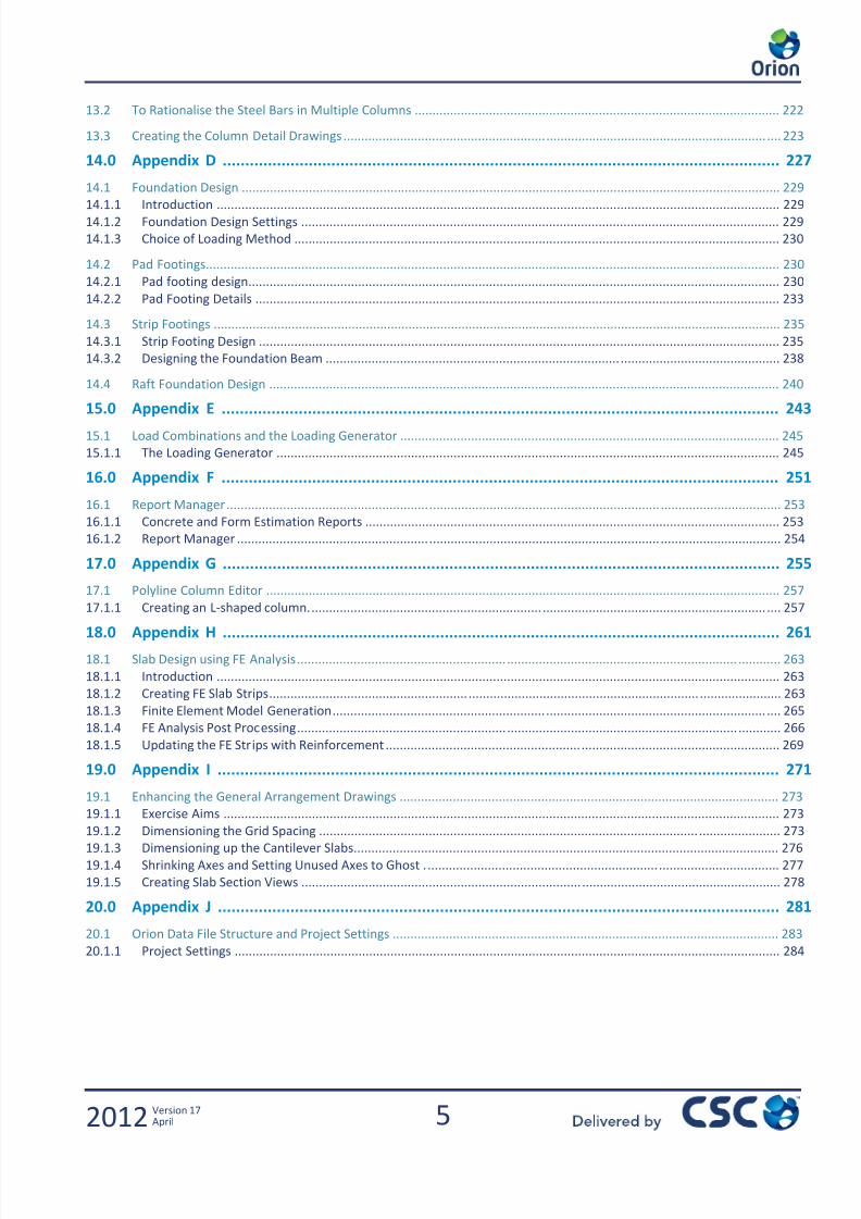
1.4 Orion Modelling, Analysis & Design Flowchart
The following flow chart demonstrates the typical procedure, for analysis and design within Orion. These options are fully
described in the Orion Engineers Handbook
4.1 Beam Design
NO
YES
3a For Flat Slab Construction
Use FE Floor Analysis to create
sub frames per floor, and chase
gravity (only) loads down through
the structure.
These Gravity Loads replace those
from the Buildin Anal sis
4.2 Column/Wall Design 4.3 Slab Design
3. Run Building Analysis
Generates gravity and lateral
design forces for column/walls
and beams
If a Flat Slab?
(or sub frame
approach)
2. Derive Beam Loads
Yield Lines
or
FE decomposition for Beam Loads
Slab design based on tabulated code coefficients1. Build the Model
7/22/2019 Standard Training Manual
http://slidepdf.com/reader/full/standard-training-manual 14/286
13
Introduction
Graphic Editor - General Principles
2012 Version 17.0April
1.5 Graphic Editor - General Principles
In a formal training course your tutor will demonstrate these methods to you. If you’re working through the notes
independently, you should just read this section and then return to it as necessary when you need to use thefeatures/methods it describes.
1.5.1 Selecting single and / or multiple members
Several entity selection options are available to select single and/or multiple elements for editing. Only visible objects can be
selected using one of the selection methods. The entity selection options are located in the "Edit" drop down and toolbar.
Available entity selection options are:
Select Entity Option
After clicking on the "Pick" icon from the Members Toolbar, a single element can be selected by simply picking a
point on the entity.
To select a second, and further, object(s) you can press the CTRL key while picking entities successively. If a selected elementis picked again, then it will be de-selected.
Window/Crossing Selections
After clicking on the "Pick" icon from the Members Toolbar, multiple elements can be selected by enclosing them in a
selection window. A selection window is a rectangular area that is defined in the drawing area by dragging two opposite
corners.
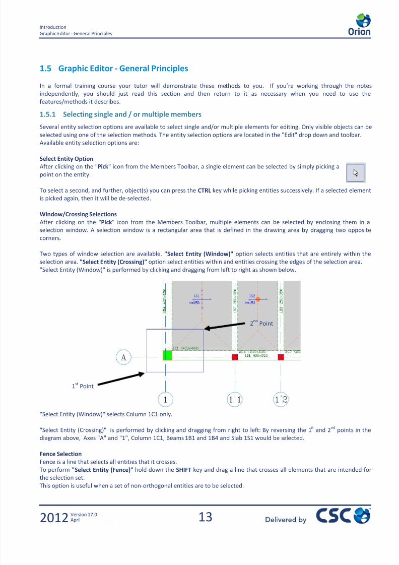
Two types of window selection are available. "Select Entity (Window)" option selects entities that are entirely within the
selection area. "Select Entity (Crossing)" option select entities within and entities crossing the edges of the selection area.
"Select Entity (Window)" is performed by clicking and dragging from left to right as shown below.
"Select Entity (Window)" selects Column 1C1 only.
"Select Entity (Crossing)" is performed by clicking and dragging from right to left: By reversing the 1st
and 2nd
points in the
diagram above, Axes "A" and "1", Column 1C1, Beams 1B1 and 1B4 and Slab 1S1 would be selected.
Fence Selection
Fence is a line that selects all entities that it crosses.
To perform "Select Entity (Fence)" hold down the SHIFT key and drag a line that crosses all elements that are intended for
the selection set.
This option is useful when a set of non-orthogonal entities are to be selected.
1st
Point
2nd
Point

7/22/2019 Standard Training Manual
http://slidepdf.com/reader/full/standard-training-manual 15/286
14
Introduction
Graphic Editor - General Principles
2012 Version 17.0April
"Select Entity (Fence)" selects Axes "A" and "B".
1.5.2 Update - Editing a member
For example, in order to edit an existing beam:
1. Select an existing beam.
2. Right mouse click and choose “Properties”
3. Change the values/settings as required
4. Press the "Update" button in the properties window.
The same process applies to all element types. You can edit multiple beams/columns/walls etc by selecting the elements you
need to edit and following the same steps as above. You can edit all elements of a particular element type by using the
member tables from the “Member” drop down menu.
1.5.3 Deletion – Single / Multiple members
To delete an element, you must first select it and then do one of the following:
1. Press the "Delete" button on your keyboard
2. Right mouse click and choose “Delete” from the context menu.
1st Point
2n
Point
7/22/2019 Standard Training Manual
http://slidepdf.com/reader/full/standard-training-manual 16/286
15
Introduction
Graphic Editor - General Principles
2012 Version 17.0April
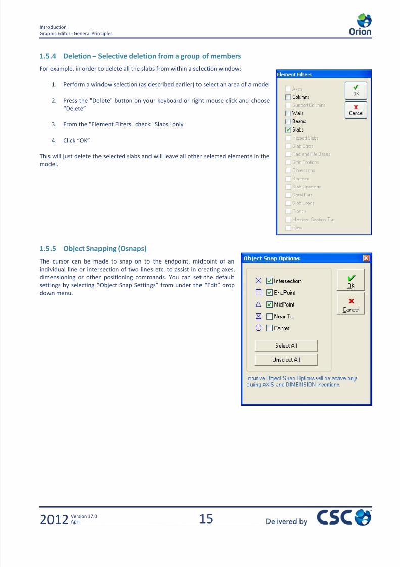
1.5.4 Deletion – Selective deletion from a group of members
For example, in order to delete all the slabs from within a selection window:
1. Perform a window selection (as described earlier) to select an area of a model
2. Press the "Delete" button on your keyboard or right mouse click and choose
“Delete”
3. From the "Element Filters" check "Slabs" only
4. Click “OK”
This will just delete the selected slabs and will leave all other selected elements in the
model.
1.5.5 Object Snapping (Osnaps)
The cursor can be made to snap on to the endpoint, midpoint of an
individual line or intersection of two lines etc. to assist in creating axes,
dimensioning or other positioning commands. You can set the default
settings by selecting “Object Snap Settings” from under the “Edit” drop
down menu.

7/22/2019 Standard Training Manual
http://slidepdf.com/reader/full/standard-training-manual 17/286
16
Introduction
Graphic Editor - General Principles
2012 Version 17.0April
1.5.6 Basic View/Zoom functions
The Graphical Editor provides several ways to control the display of the drawing in the drawing area. You can zoom to change
the magnification or pan to reposition the view in the drawing area. All display control options are located in the "View" drop
down and the toolbar.
The following options are available:
Regen
The "Regen" command re-generates all drawing entities using stored geometry information. This command is slightly time
consuming than the redraw function.
Zoom Window
You can quickly zoom in on an area by picking the opposite corners of the zoom window defining it.
After selecting the "Zoom Window" option, specify the opposite corners of the zoom window in the drawing area by dragging
two points.
Zoom Previous
All zoom operations are stored. So, anytime, a previous display can be recalled using the "Zoom Previous" option.
Zoom Extents
"Zoom Extents" displays a view that includes all objects in the current storey at the highest magnification that will fit in the
drawing area.
Zoom Limits
"Zoom Limits" displays a view that includes all objects contained within the active sheet borders at the highest magnification
that will fit in the drawing area.
Pan
After selecting the "Pan" option, you can pan the drawing image to a new location by left clicking and dragging from one
point to another.
This function can also be achieved by depressing the scroll wheel on your mouse and then moving the cursor around the
screen.
Zoom In (20%) and Zoom Out (20%)
"Zoom In (20%)" increases the magnification of the current view by 20% and "Zoom Out (20%)" decreases the magnificationby a similar amount. This option can be used to quickly zoom in and out to the centre of the current view.
This function can also be achieved by using the scroll wheel on your mouse. The Zoom will be focussed on wherever the
cursor is placed on the screen.

7/22/2019 Standard Training Manual
http://slidepdf.com/reader/full/standard-training-manual 18/286
17
Building the Model
2012 Version 17.0April
2.0 Building the Model
Modelling Fundamentals

7/22/2019 Standard Training Manual
http://slidepdf.com/reader/full/standard-training-manual 19/286
7/22/2019 Standard Training Manual
http://slidepdf.com/reader/full/standard-training-manual 20/286
19
Building the Model
Getting Started – Project Parameters & Settings
2012 Version 17.0April
2.1 Getting Started – Project Parameters & Settings
2.1.1 Exercise aims
Launching Orion software
Entering Project Code
Selecting a Template (Settings Centre)
Selecting Drawing Sheet
Entering Storey Height
Specifying some Program Design Settings
The object of this exercise is to familiarise you on how to start a new project in Orion and how to input some basic project
parameters.
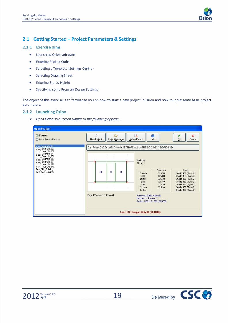
2.1.2 Launching Orion
Open Orion so a screen similar to the following appears.
7/22/2019 Standard Training Manual
http://slidepdf.com/reader/full/standard-training-manual 21/286
20
Building the Model
Getting Started – Project Parameters & Settings
2012 Version 17.0April
2.1.3 Creating a New Project
Click New Project
Enter a Project Code. Type the code as shown using the ‘_’ character to denote spaces.
Then Click OK
This will automatically create a folder called Training_Course_Model_1 beneath the default data folder shown on the
previous page. This will be used for storing all the model data.
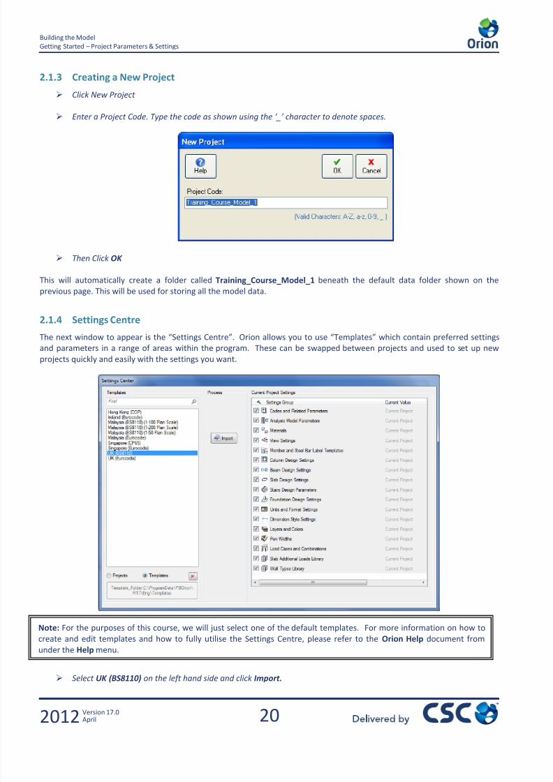
2.1.4 Settings Centre
The next window to appear is the “Settings Centre”. Orion allows you to use “Templates” which contain preferred settings
and parameters in a range of areas within the program. These can be swapped between projects and used to set up new
projects quickly and easily with the settings you want.
Select UK (BS8110) on the left hand side and click Import.
Note: For the purposes of this course, we will just select one of the default templates. For more information on how to
create and edit templates and how to fully utilise the Settings Centre, please refer to the Orion Help document from
under the Help menu.
7/22/2019 Standard Training Manual
http://slidepdf.com/reader/full/standard-training-manual 22/286
21
Building the Model
Getting Started – Project Parameters & Settings
2012 Version 17.0April
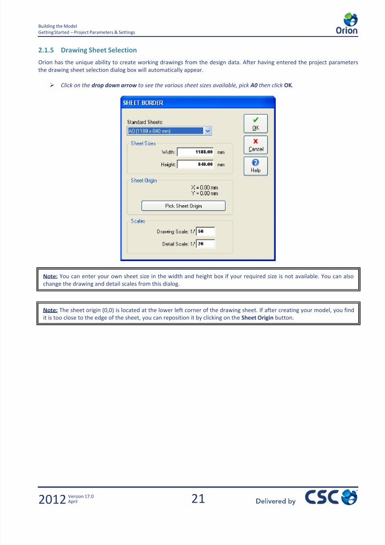
2.1.5 Drawing Sheet Selection
Orion has the unique ability to create working drawings from the design data. After having entered the project parameters
the drawing sheet selection dialog box will automatically appear.
Click on the drop down arrow to see the various sheet sizes available, pick A0 then click OK.
Note: You can enter your own sheet size in the width and height box if your required size is not available. You can also
change the drawing and detail scales from this dialog.
Note: The sheet origin (0,0) is located at the lower left corner of the drawing sheet. If after creating your model, you find
it is too close to the edge of the sheet, you can reposition it by clicking on the Sheet Origin button.

7/22/2019 Standard Training Manual
http://slidepdf.com/reader/full/standard-training-manual 23/286
22
Building the Model
Getting Started – Project Parameters & Settings
2012 Version 17.0April
2.1.6 Inserting Storey Height
The next dialog prompts for the Storey height for the 1st
storey
Enter the storey height as 3300mm as shown below then click OK.
After entering the 1st
storey height, the main drawing area (Graphical Editor) appears.
Orion is now fully open and ready for our model to be created.

7/22/2019 Standard Training Manual
http://slidepdf.com/reader/full/standard-training-manual 24/286
23
Building the Model
Creating Axes
2012 Version 17.0April
2.2 Creating Axes
2.2.1 Exercise Aims
Understanding Axis Directions
Using the Orthogonal Axis Generator
Rotating & Stretching Axes
Selecting Multiple Axes
2.2.2 Establishing Axis Directions and Labels
Now we will begin to create the axes.
Pick Orthogonal Axis Generator from the File menu.
Note the text that is displayed at the bottom of the screen. This is prompting you how to proceed.
Hold down the Ctrl key while picking a point in the lower left hand region of the drawing sheet.
After picking the reference point the Orthogonal Axis Generator screen should appear.
Fill in the boxes on the Orthogonal Axis Generator as below.
Note: You could now click on the screen to define the co-ordinates of the reference point, however to ensure it has a
sensible (i.e. whole number) offset from the origin hold down the Ctrl key on your keyboard while picking a reference
point.
7/22/2019 Standard Training Manual
http://slidepdf.com/reader/full/standard-training-manual 25/286
24
Building the Model
Creating Axes
2012 Version 17.0April
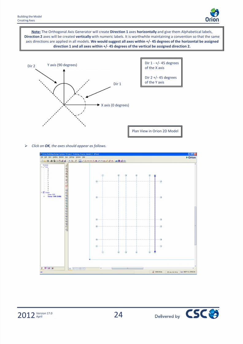
Click on OK , the axes should appear as follows.
Plan View in Orion 2D Model
X axis (0 degrees)
Y axis (90 degrees)Dir 1 - +/- 45 degrees
of the X axis
Dir 2 +/- 45 degrees
of the Y axisDir 1
Dir 2
Note: The Orthogonal Axis Generator will create Direction 1 axes horizontally and give them Alphabetical labels,
Direction 2 axes will be created vertically with numeric labels. It is worthwhile maintaining a convention so that the same
axis directions are applied in all models. We would suggest all axes within +/- 45 degrees of the horizontal be assigned
direction 1 and all axes within +/- 45 degrees of the vertical be assigned direction 2.

7/22/2019 Standard Training Manual
http://slidepdf.com/reader/full/standard-training-manual 26/286

7/22/2019 Standard Training Manual
http://slidepdf.com/reader/full/standard-training-manual 27/286

7/22/2019 Standard Training Manual
http://slidepdf.com/reader/full/standard-training-manual 28/286
27
Building the Model
Creating Axes
2012 Version 17.0April
Repeat this procedure to rotate axis F by 10 degrees about the intersection of axes F and 1.
The axes should then appear as follows:
2.2.6 Selecting/Stretching Multiple Axes
Next we will stretch all the vertical axes so that they all extend above axis F.
From the Edit menu choose Select Entity (Fence) and then drag a line between Axis E & F through all the
vertical axes so they are all selected.
Right mouse click to bring up the pop-up menu and pick Stretch Axis
Click and Hold with your left mouse button near Axis 6 and drag up past Axis F.
The screen should now look as shown below.
Help?? If you can’t recall how to do the above:
Click the Pick icon
Click on Axis F to select it.Right mouse click and choose Rotate Axis
Type in the angle as 10
Click on the Osnap intersection of axis F and 1

7/22/2019 Standard Training Manual
http://slidepdf.com/reader/full/standard-training-manual 29/286
28
Building the Model
Creating Axes
2012 Version 17.0April
2.2.7 Creating Axes Individually
In the training example it has been possible to create all the Axis Lines using the Orthogonal Axis Generator so it will not be
necessary to create axes individually, however there will be many occasions in other models when you will need to add
individual axes to an existing grid layout. There are two ways to achieve this:
Either;
1. Create a new line parallel to an existing axis. To do this, select an existing grid line then right click to activate the
context sensitive pop up menu. Choose Offset Axis. Define the offset and the label for the new axis and then left
mouse click to one side of the initially selected axis to indicate the side where the new axis is to be drawn.
2. Create a new line by using the Axis Tool. To do this, select the Axis Tool from the Members Toolbar.
Define the new label, then left click and drag to draw the axis. Note that using this method the line is
being drawn ‘free-hand’ making it difficult to draw the line to an exact angle or length. To rectify this, hold
down the CTRL key when drawing the line. This forces the angle and length to snap to multiples of the
values shown in the Graphic Editor View Settings – Plan Tab.
With an Angle Step of 15 deg and a Length Step of 1000, holding down CTRL will force the axis to snap to an angle of
0,15, or 30 degrees etc. and a length which will be a multiple of 1000mm.
7/22/2019 Standard Training Manual
http://slidepdf.com/reader/full/standard-training-manual 30/286
7/22/2019 Standard Training Manual
http://slidepdf.com/reader/full/standard-training-manual 31/286
30
Building the Model
Creating Columns
2012 Version 17.0April
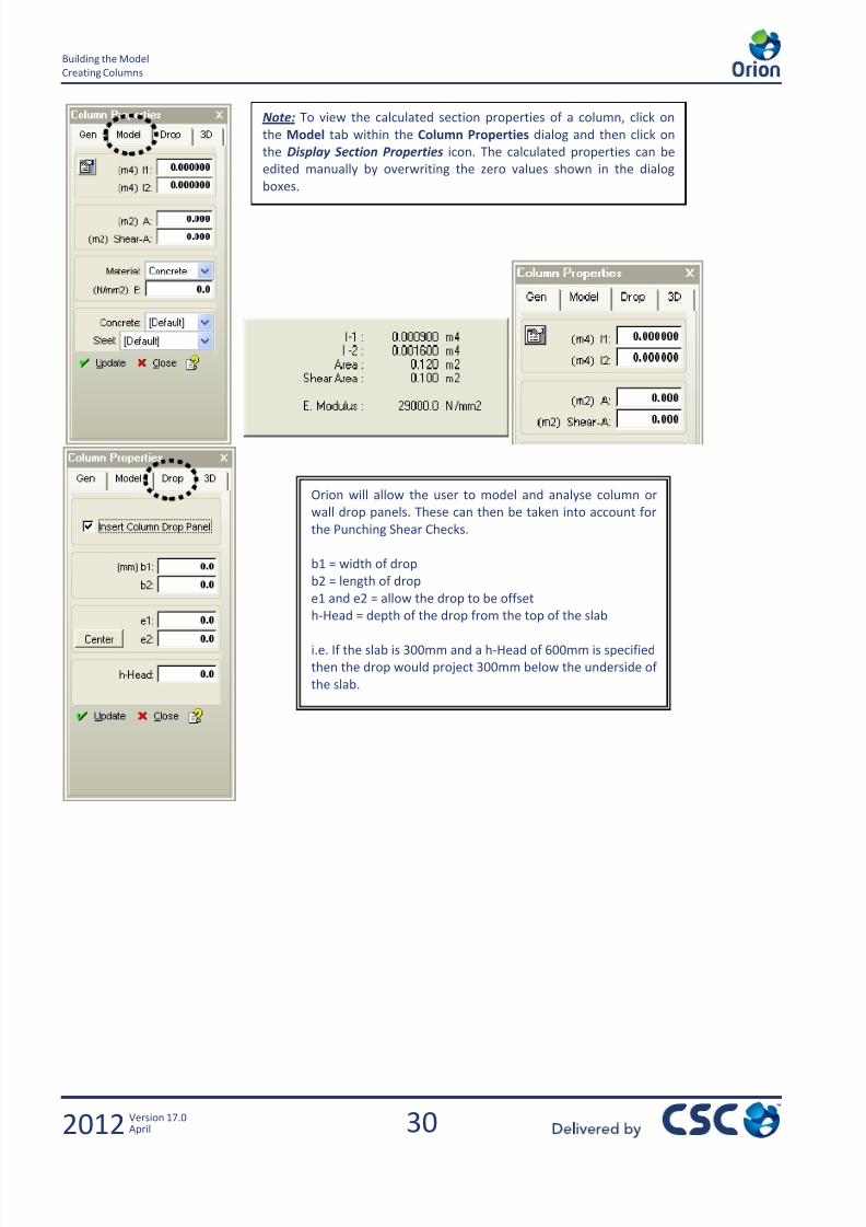
Note: To view the calculated section properties of a column, click on
the Model tab within the Column Properties dialog and then click on
the Display Section Properties icon. The calculated properties can be
edited manually by overwriting the zero values shown in the dialog
boxes.
Orion will allow the user to model and analyse column or
wall drop panels. These can then be taken into account for
the Punching Shear Checks.
b1 = width of drop
b2 = length of drop
e1 and e2 = allow the drop to be offset
h-Head = depth of the drop from the top of the slab
i.e. If the slab is 300mm and a h-Head of 600mm is specified
then the drop would project 300mm below the underside of
the slab.

7/22/2019 Standard Training Manual
http://slidepdf.com/reader/full/standard-training-manual 32/286
31
Building the Model
Creating Columns
2012 Version 17.0April
Support Types > [Default]. The Default support condition is defined in Member > Support Type Definitions. The user can
define additional support conditions for translation / rotation in the x, y and z axis.
(mm) del z (top/bot) – The user can define different top and bottom levels for each column relative to the datum, i.e. for a
sloping site.
Plane (top/bot) – If a column/wall has been assigned to a Plane (i.e. for a sloping floor) then this Plane is referenced and the
appropriate del z setting is made inactive.

7/22/2019 Standard Training Manual
http://slidepdf.com/reader/full/standard-training-manual 33/286
32
Building the Model
Creating Columns
2012 Version 17.0April
2.3.3 Creating Rectangular Columns
We will start by creating some rectangular columns.
The 1st column we will create will be of size 600x300 where 600 will be in direction 1. Also these columns are to be parallel tothe grids in both directions 1 and 2.
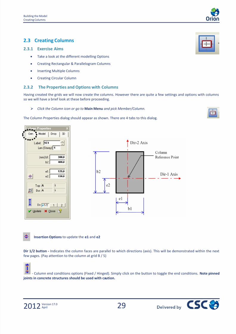
Click the Dir 1/2 button to indicate the column faces are parallel to both directions 1 and 2.
In the dimensions box enter 600 in b1 and 300 in b2
Click the centrally placed column icon from the Insertion Options to update the e1 and e2 values as shown to the
right.
The Column Properties should now be as shown below.
Label Corner - Allows the user to define the label position relative to its four corners.
Note: By right clicking on these boxes we can select a dimension from those available instead of typing a value.
7/22/2019 Standard Training Manual
http://slidepdf.com/reader/full/standard-training-manual 34/286
33
Building the Model
Creating Columns
2012 Version 17.0April
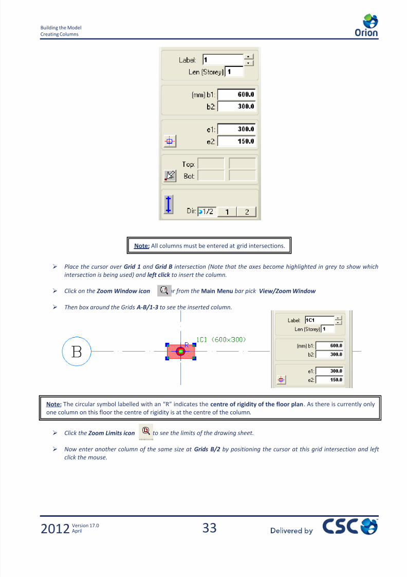
Place the cursor over Grid 1 and Grid B intersection (Note that the axes become highlighted in grey to show which
intersection is being used) and left click to insert the column.
Click on the Zoom Window icon or from the Main Menu bar pick View/Zoom Window
Then box around the Grids A-B/1-3 to see the inserted column.
Click the Zoom Limits icon to see the limits of the drawing sheet.
Now enter another column of the same size at Grids B/2 by positioning the cursor at this grid intersection and left
click the mouse.
Note: All columns must be entered at grid intersections.
Note: The circular symbol labelled with an “R” indicates the centre of rigidity of the floor plan . As there is currently only
one column on this floor the centre of rigidity is at the centre of the column.
7/22/2019 Standard Training Manual
http://slidepdf.com/reader/full/standard-training-manual 35/286
34
Building the Model
Creating Columns
2012 Version 17.0April
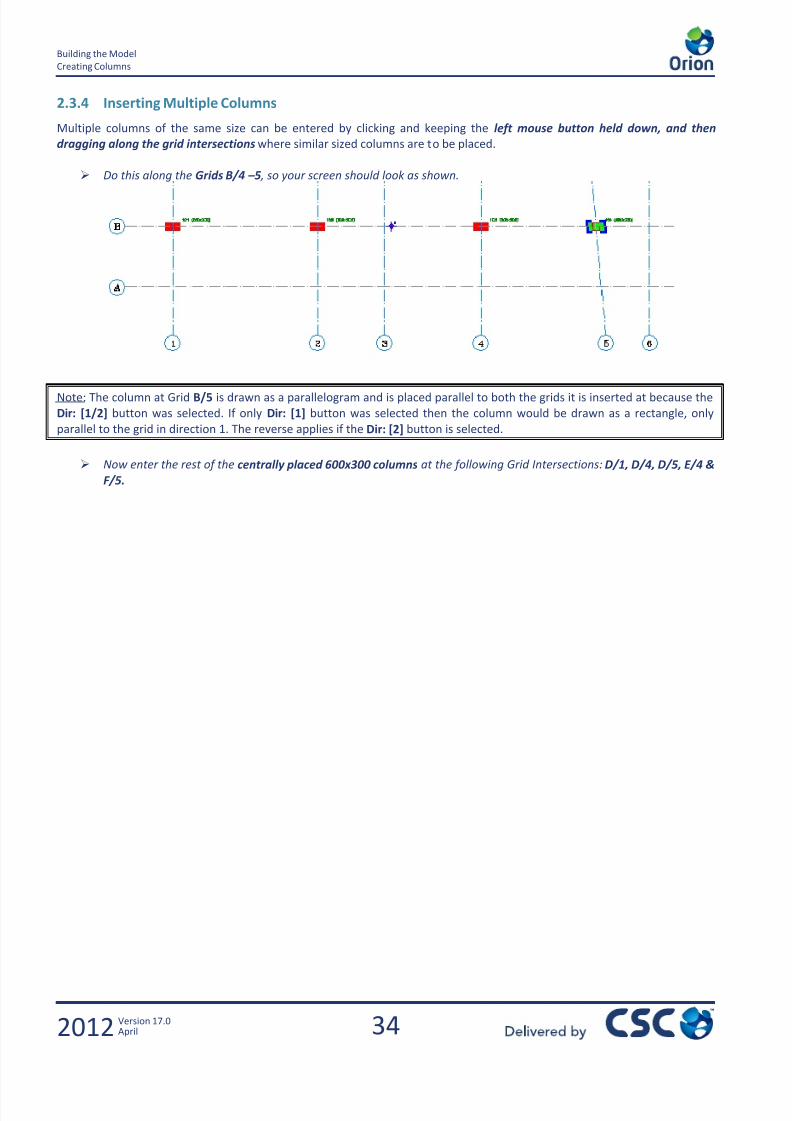
2.3.4 Inserting Multiple Columns
Multiple columns of the same size can be entered by clicking and keeping the left mouse button held down, and then
dragging along the grid intersections where similar sized columns are to be placed.
Do this along the Grids B/4 – 5 , so your screen should look as shown.
Note: The column at Grid B/5 is drawn as a parallelogram and is placed parallel to both the grids it is inserted at because the
Dir: [1/2] button was selected. If only Dir: [1] button was selected then the column would be drawn as a rectangle, only
parallel to the grid in direction 1. The reverse applies if the Dir: [2] button is selected.
Now enter the rest of the centrally placed 600x300 columns at the following Grid Intersections: D/1, D/4, D/5, E/4 &
F/5.

7/22/2019 Standard Training Manual
http://slidepdf.com/reader/full/standard-training-manual 36/286
35
Building the Model
Creating Columns
2012 Version 17.0April
So your screen should look as follows.
Centrally Placed 600x300 Sized Columns
Now with the properties for the 600x300 column active, use the
Insertion Options to align the column so that its top left corner is
positioned flush with the grids. With the alignment as shown, the
eccentricities should change to e1=0 and e2=300.
Then enter the column at Grid F/1
Click on the Zoom Extents icon so your screen should look as
below.
7/22/2019 Standard Training Manual
http://slidepdf.com/reader/full/standard-training-manual 37/286
36
Building the Model
Creating Columns
2012 Version 17.0April
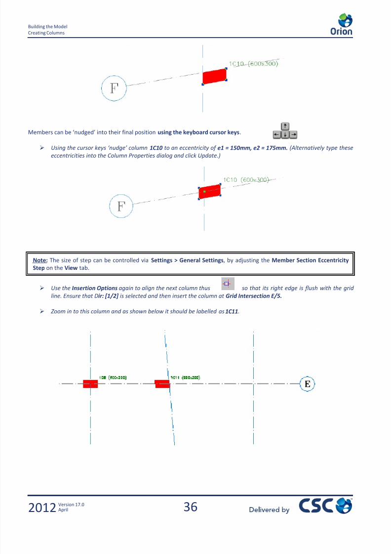
Members can be ‘nudged’ into their final position using the keyboard cursor keys.
Using the cursor keys ‘nudge’ column 1C10 to an eccentricity of e1 = 150mm, e2 = 175mm. (Alternatively type these
eccentricities into the Column Properties dialog and click Update.)
Use the Insertion Options again to align the next column thus so that its right edge is flush with the grid
line. Ensure that Dir: [1/2] is selected and then insert the column at Grid Intersection E/5.
Zoom in to this column and as shown below it should be labelled as 1C11.
Note: The size of step can be controlled via Settings > General Settings, by adjusting the Member Section Eccentricity
Step on the View tab.
7/22/2019 Standard Training Manual
http://slidepdf.com/reader/full/standard-training-manual 38/286

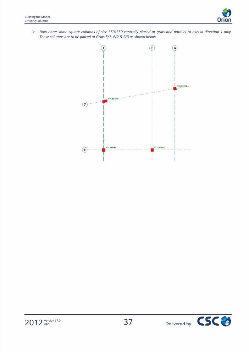
7/22/2019 Standard Training Manual
http://slidepdf.com/reader/full/standard-training-manual 39/286
38
Building the Model
Creating Columns
2012 Version 17.0April
2.3.5 Creating Circular Columns
Now we will enter a circular column 400mm in diameter.
Type 400 in the b1 box and leave b2, e1 & e2 as 0 , then click on Grid F/4 to
enter the circular column.
View of Circular Column 1C15
2.3.6 Using the Polyline Column Editor
This option allows the user to specify any shape column for the analysis and design. Please refer to the Help system for
information on how to use the ‘Polyline Column Editor’.
Note: To enter a void in the centre of the column, put a negative value in
the b2 box (i.e. 100mm pipe would be entered as -100).
7/22/2019 Standard Training Manual
http://slidepdf.com/reader/full/standard-training-manual 40/286
39
Building the Model
Creating Columns
2012 Version 17.0April
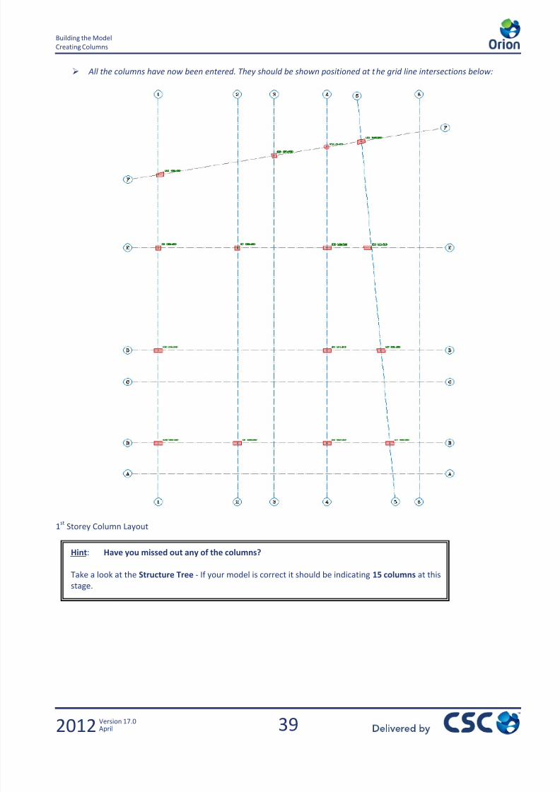
All the columns have now been entered. They should be shown positioned at the grid line intersections below:
1st
Storey Column Layout
Hint: Have you missed out any of the columns?
Take a look at the Structure Tree - If your model is correct it should be indicating 15 columns at this
stage.

7/22/2019 Standard Training Manual
http://slidepdf.com/reader/full/standard-training-manual 41/286
40
Building the Model
Creating Shear Walls
2012 Version 17.0April
2.4 Creating Shear Walls
2.4.1 Exercise Aims
Creating C-Shaped Core Wall
2.4.2 Overview of Options
You will see many of the options are similar to the options in the columns dialog but there are a few that refer to walls only.
Ext I Ext J
The geometry of the wall is defined under the Gen
tab. The wall is defined between grid points.
Extension zones (Ext) can also be defined to modelthe physical position of the wall.
Note – It is recommended that the extension
zones are kept to a minimum as shown below.
The orientation of the wall is defined by the label
direction. This is controlled automatically by Orion.
In simple terms Ext I refers to the start of the wall,
and Ext J to the end.

7/22/2019 Standard Training Manual
http://slidepdf.com/reader/full/standard-training-manual 42/286
41
Building the Model
Creating Shear Walls
2012 Version 17.0April
Material Properties – The choice of material can be controlled on a
wall by wall basis. However it is recommended to use the [Default]
material properties controlled by the Parameter Settings.
It is recommended that changing any material properties in this
window should be done with caution.
(mm) del z (I,bot) – The base levels of ends I can be controlled based
off the datum.
(mm) del z (J,bot) – The base levels of ends J can be controlled based
off the datum.
This enables sloping base of walls.
Support Type – The support Types can be defined as per thecolumns. It is recommended to use [Default] settings.
Wall Model Type –The analytical model for this shear wall can be
controlled on an individual basis. The Mid-Pier and FE Shell Methods
are described fully in the Engineers Handbook.
It is recommended to leave this setting as Default.
Mid Pier Model
FE Shell Model
7/22/2019 Standard Training Manual
http://slidepdf.com/reader/full/standard-training-manual 43/286
42
Building the Model
Creating Shear Walls
2012 Version 17.0April
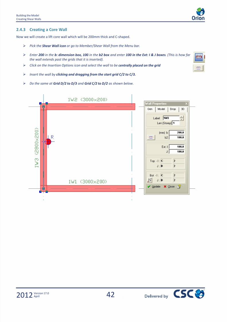
2.4.3 Creating a Core Wall
Now we will create a lift core wall which will be 200mm thick and C-shaped.
Pick the Shear Wall icon or go to Member/Shear Wall from the Menu bar.
Enter 200 in the b: dimension box, 100 in the b2 box and enter 100 in the Ext: I & J boxes. (This is how farthe wall extends past the grids that it is inserted).
Click on the Insertion Options icon and select the wall to be centrally placed on the grid
Insert the wall by clicking and dragging from the start grid C/2 to C/3.
Do the same at Grid D/2 to D/3 and Grid C/2 to D/2 as shown below.
7/22/2019 Standard Training Manual
http://slidepdf.com/reader/full/standard-training-manual 44/286

7/22/2019 Standard Training Manual
http://slidepdf.com/reader/full/standard-training-manual 45/286
44
Building the Model
Creating Beams
2012 Version 17.0April
The beam along Grid B/1-6 is to be placed in the centre of Grid B so that the b2 dimension is half of the b dimension,
Ensure this by clicking on the icon this will automatically set the b2 dimension to 150mm as shown above left.
The beam is positioned at Grid B/1-6 by left clicking and dragging from the start of Grid B/1 and releasing when your
cursor is at Grid B/6 so that 4 beams are entered as shown below.
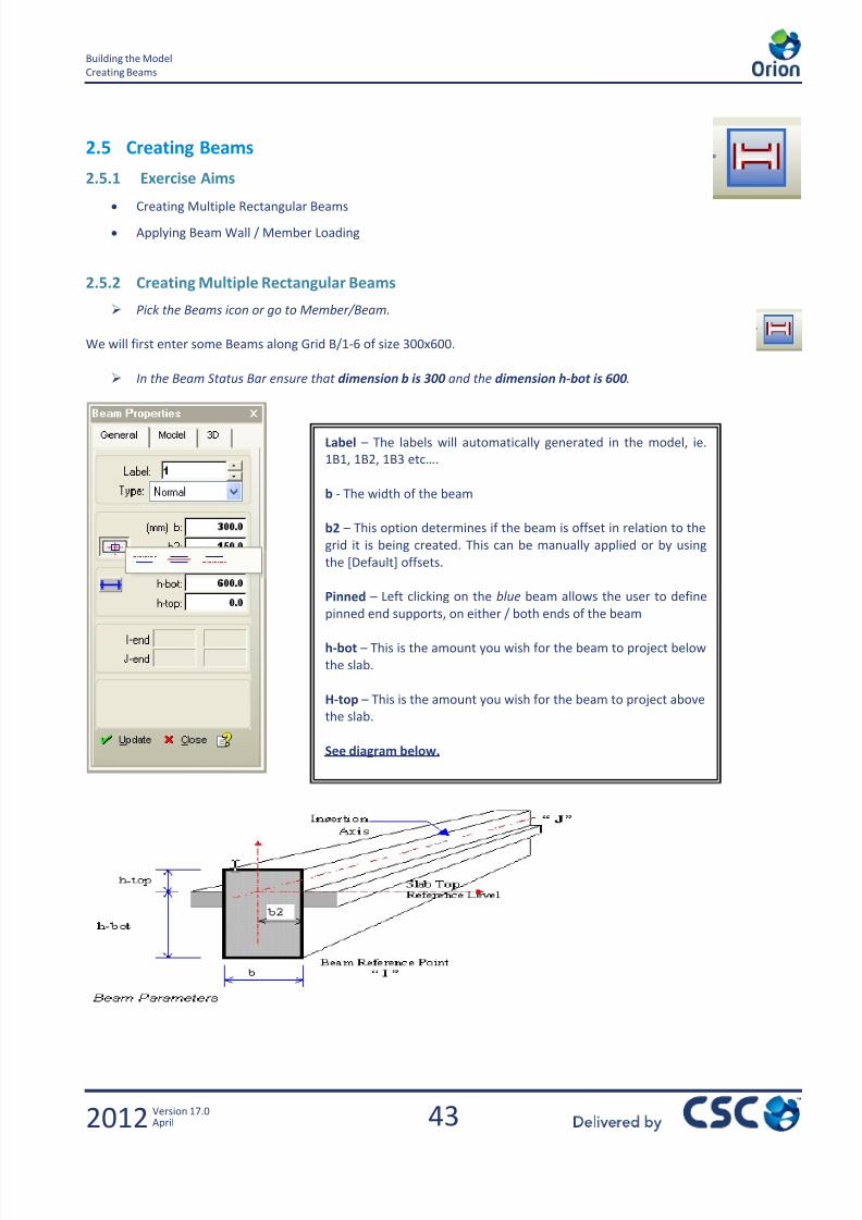
I / Shear Area / hf / bf and E – These will all be calculated automatically
based on the Material Properties / Beam Size and the connecting slabs for
the calculation of the flanges.
Note:Like the columns, the beams are automatically labelled based on the storey and numbered sequentially as they are
entered.
Orion has automatically split the beam into four individual members between the columns.

7/22/2019 Standard Training Manual
http://slidepdf.com/reader/full/standard-training-manual 46/286
45
Building the Model
Creating Beams
2012 Version 17.0April
Now enter some more beams in the following order of same size at the following locations:
From To Beam Size
D/1 D/6 300 x 600
E/1 E/5 300 x 600
2/A 2/C 300 x 600
4/A 4/F 300 x 600
1/A 1/F 300 x 600
5/A 5/F 300 x 600
6/B 6/D 300 x 600
So your screen should look as shown on the next page.
7/22/2019 Standard Training Manual
http://slidepdf.com/reader/full/standard-training-manual 47/286
46
Building the Model
Creating Beams
2012 Version 17.0April
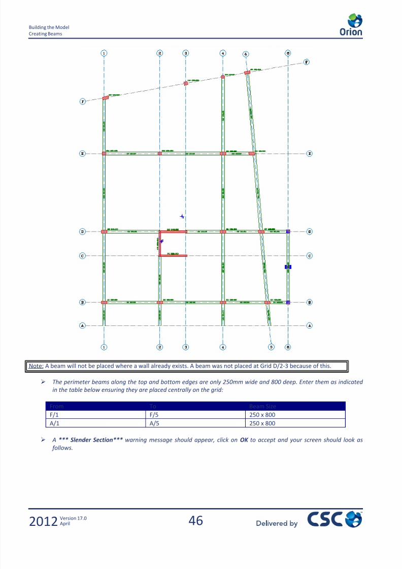
Note: A beam will not be placed where a wall already exists. A beam was not placed at Grid D/2-3 because of this.
The perimeter beams along the top and bottom edges are only 250mm wide and 800 deep. Enter them as indicated
in the table below ensuring they are placed centrally on the grid:
From To Beam Size
F/1 F/5 250 x 800
A/1 A/5 250 x 800
A *** Slender Section*** warning message should appear, click on OK to accept and your screen should look as
follows.

7/22/2019 Standard Training Manual
http://slidepdf.com/reader/full/standard-training-manual 48/286

7/22/2019 Standard Training Manual
http://slidepdf.com/reader/full/standard-training-manual 49/286
48
Building the Model
Creating Beams
2012 Version 17.0April
Hint:
Have you missed out any
of the beams?
Take a look at theStructure Tree - It should
indicate 37 beams.
Note: When you place the beams between C/3 and C/5 you will see a message about sub-dividing these beams with the
beam running along axis 4 – Click Yes to sub-divide
1st
Storey Beam Layout
7/22/2019 Standard Training Manual
http://slidepdf.com/reader/full/standard-training-manual 50/286
49
Building the Model
Creating Slabs
2012 Version 17.0April
2.6 Creating Slabs
2.6.1 Exercise Aims
Creating 2 way spanning Slabs
Creating Cantilever Slabs
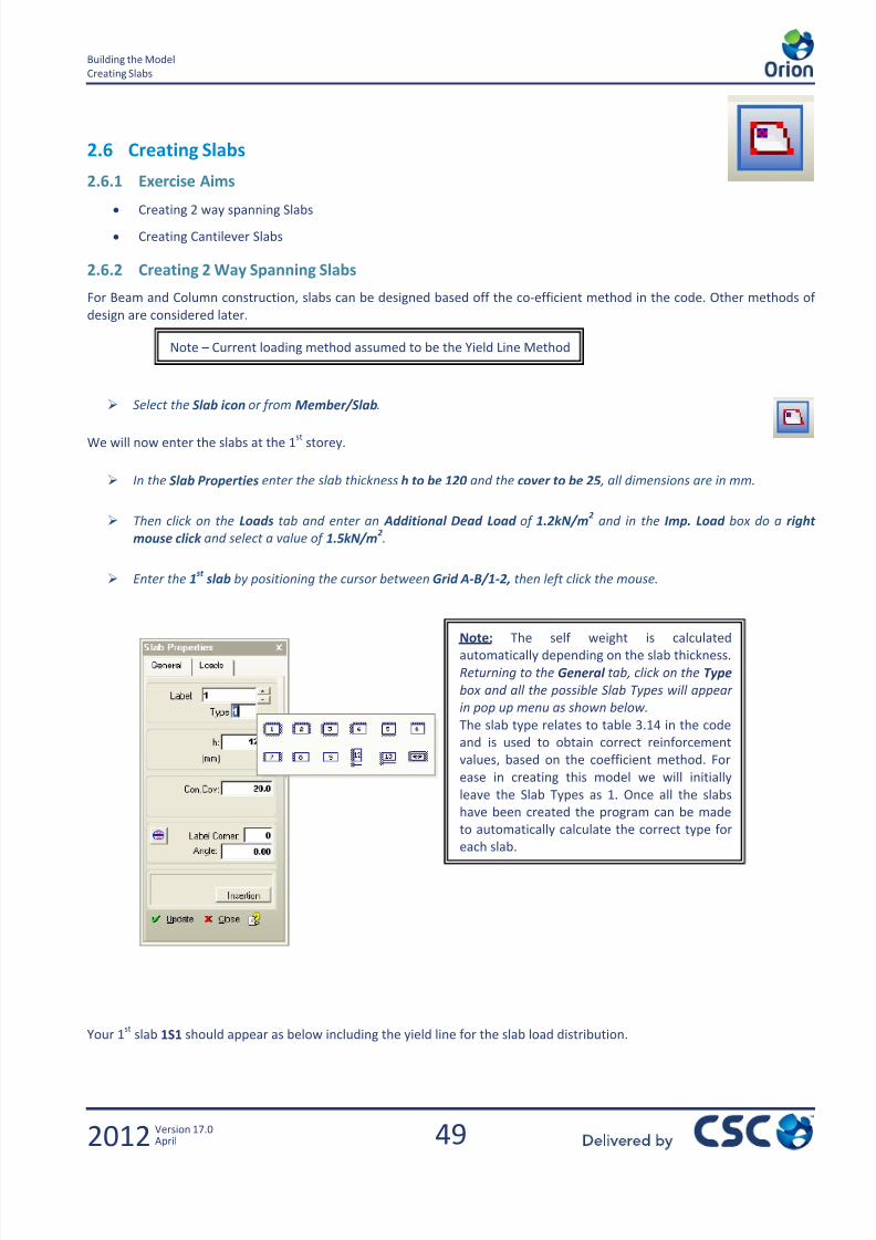
2.6.2 Creating 2 Way Spanning Slabs
For Beam and Column construction, slabs can be designed based off the co-efficient method in the code. Other methods of
design are considered later.
Select the Slab icon or from Member/Slab.
We will now enter the slabs at the 1st
storey.
In the Slab Properties enter the slab thickness h to be 120 and the cover to be 25 , all dimensions are in mm.
Then click on the Loads tab and enter an Additional Dead Load of 1.2kN/m2 and in the Imp. Load box do a right
mouse click and select a value of 1.5kN/m2.
Enter the 1st
slab by positioning the cursor between Grid A-B/1-2, then left click the mouse.
Your 1st
slab 1S1 should appear as below including the yield line for the slab load distribution.
Note – Current loading method assumed to be the Yield Line Method
Note: The self weight is calculatedautomatically depending on the slab thickness.
Returning to the General tab, click on the Type
box and all the possible Slab Types will appear
in pop up menu as shown below.
The slab type relates to table 3.14 in the code
and is used to obtain correct reinforcement
values, based on the coefficient method. For
ease in creating this model we will initially
leave the Slab Types as 1. Once all the slabs
have been created the program can be made
to automatically calculate the correct type for
each slab.
7/22/2019 Standard Training Manual
http://slidepdf.com/reader/full/standard-training-manual 51/286
50
Building the Model
Creating Slabs
2012 Version 17.0April
Repeat this process to define two more 120 thick slabs as follows:
Region Thickness (mm) Dead Load (kN/m) Live Load (kN/m)
A/2 – B/4 120 1.2 1.5
A/4 – B/5 120 1.2 1.5
So now your screen should look as follows:
Now enter some 150 thk slabs which have the same Additional Dead Load as the existing ones but are to have an
Imp. Load of 3kN/m2
Region Thickness (mm) Dead Load (kN/m) Live Load (kN/m)
C/3 – D/4 150 1.2 3.0
C/4 – D/5 150 1.2 3.0
D/4 – E/5 150 1.2 3.0
E/3 – F/4 150 1.2 3.0
E/4 –F/5 150 1.2 3.0
B/5 – D/6 150 1.2 3.0
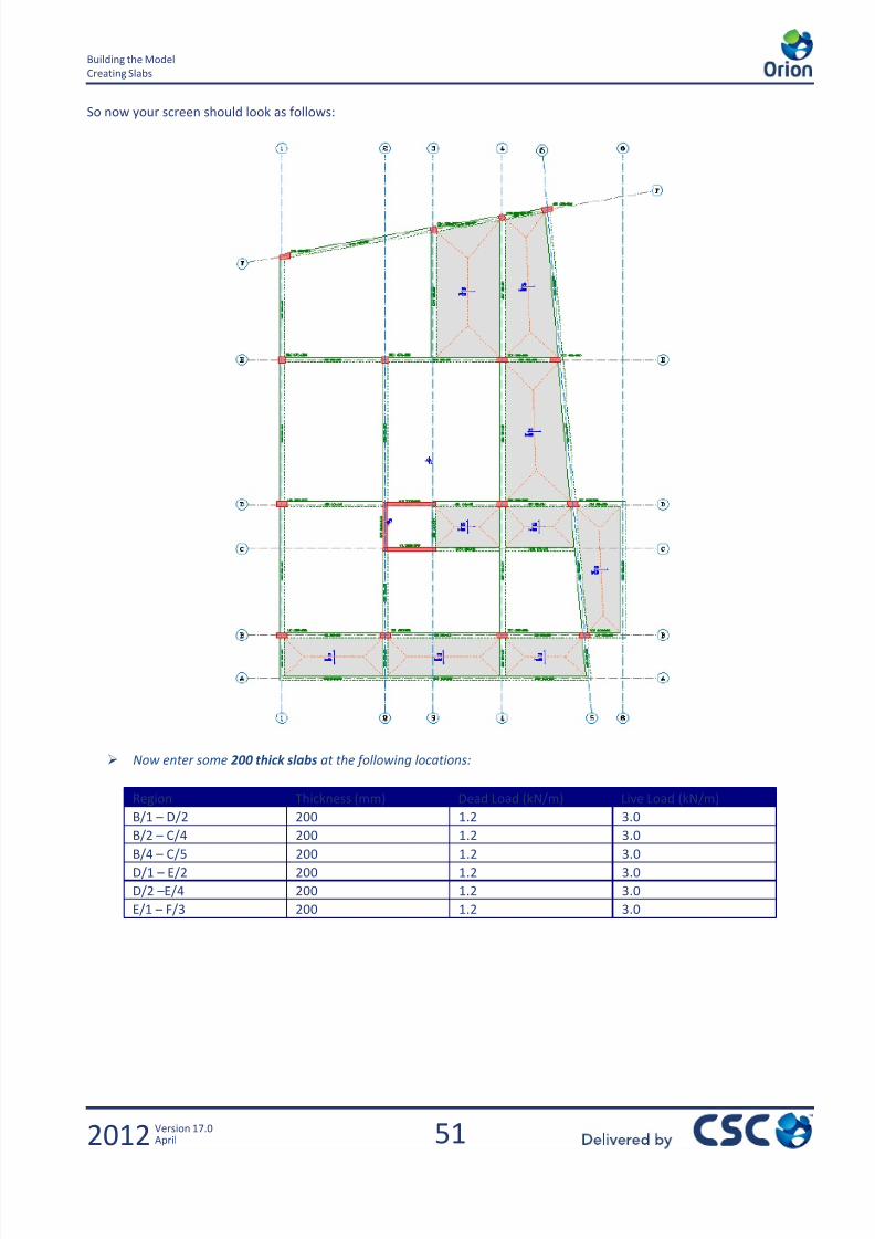
7/22/2019 Standard Training Manual
http://slidepdf.com/reader/full/standard-training-manual 52/286
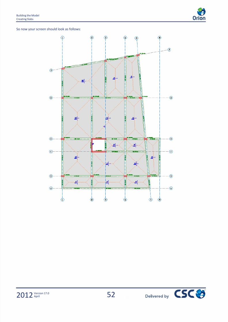
7/22/2019 Standard Training Manual
http://slidepdf.com/reader/full/standard-training-manual 53/286
52
Building the Model
Creating Slabs
2012 Version 17.0April
So now your screen should look as follows:

7/22/2019 Standard Training Manual
http://slidepdf.com/reader/full/standard-training-manual 54/286
53
Building the Model
Creating Slabs
2012 Version 17.0April
2.6.3 Setting Slab Types Automatically
To automatically set the slab types in accordance with table 3.14 proceed as follows:
Clear any members that are currently selected by clicking on the Clear Selection Set icon
Right mouse click on the Slabs folder in the Structure Tree and select Set Slab Types Automatically as shown below
The Slab Type Determination dialog appears as shown below:
Click on OK to proceed
Click on OK once more.
Note – For continuity of the slab type
to be considered, the adjoining slab
edge must be 70% or greater in
length.
Note – This message confirms how
many slabs are in the model, how
many of them have openings and
displays the Slab Type that has been
assigned to them.
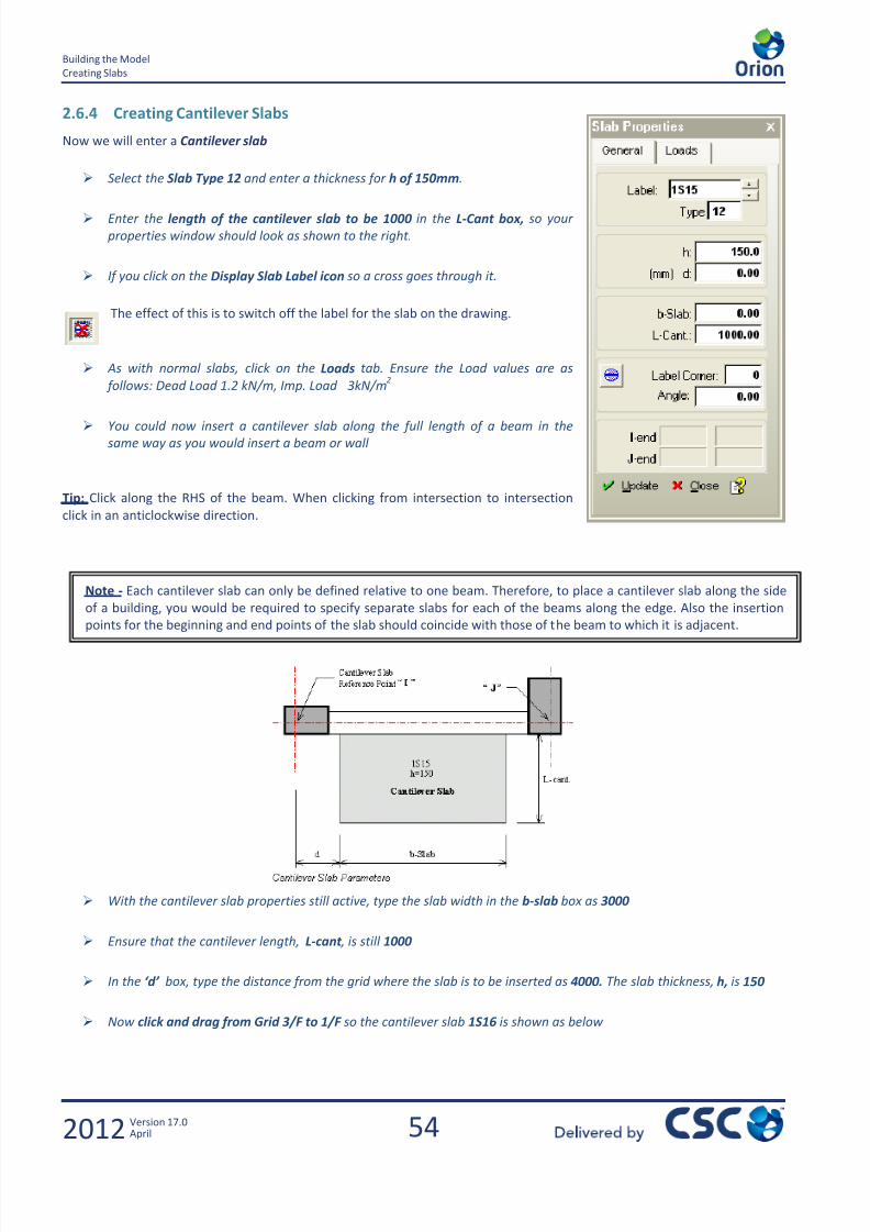
7/22/2019 Standard Training Manual
http://slidepdf.com/reader/full/standard-training-manual 55/286
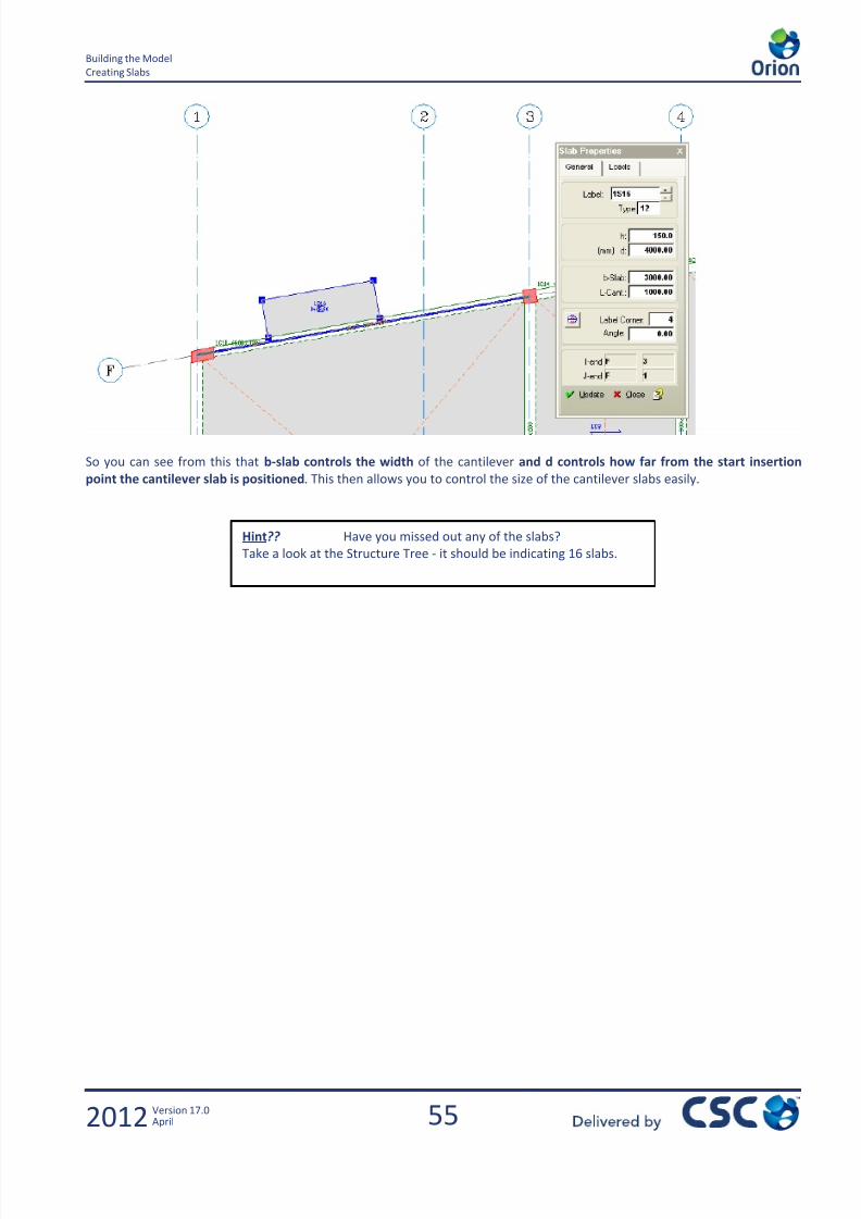
7/22/2019 Standard Training Manual
http://slidepdf.com/reader/full/standard-training-manual 56/286
55
Building the Model
Creating Slabs
2012 Version 17.0April
So you can see from this that b-slab controls the width of the cantilever and d controls how far from the start insertion
point the cantilever slab is positioned. This then allows you to control the size of the cantilever slabs easily.
Hint?? Have you missed out any of the slabs?
Take a look at the Structure Tree - it should be indicating 16 slabs.
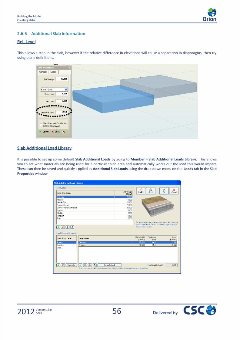
7/22/2019 Standard Training Manual
http://slidepdf.com/reader/full/standard-training-manual 57/286
56
Building the Model
Creating Slabs
2012 Version 17.0April
2.6.5 Additional Slab Information
Rel. Level
This allows a step in the slab, however if the relative difference in elevations will cause a separation in diaphragms, then try
using plane definitions.
Slab Additional Load Library
It is possible to set up some default Slab Additional Loads by going to Member > Slab Additional Loads Library. This allows
you to set what materials are being used for a particular slab area and automatically works out the load this would impart.
These can then be saved and quickly applied as Additional Slab Loads using the drop down menu on the Loads tab in the Slab
Properties window.
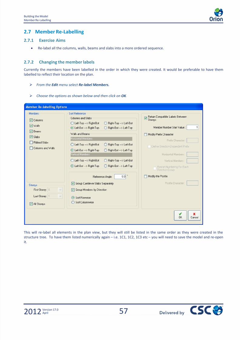
7/22/2019 Standard Training Manual
http://slidepdf.com/reader/full/standard-training-manual 58/286

7/22/2019 Standard Training Manual
http://slidepdf.com/reader/full/standard-training-manual 59/286
58
Building the Model
Using Tables to Edit Multiple Members
2012 Version 17.0April
2.8 Using Tables to Edit Multiple Members
2.8.1 Exercise Aims
Changing properties of multiple members in one go by using the member tables
2.8.2 Changing Properties of Multiple Members
To demonstrate this function we shall change the slab thickness of all the slabs in the model.
Clear any previous selections by clicking on the Clear Selection Set icon
Right click and choose Member Tables > Slab Table
This same option is available from Member > Member Tables > Slab Table.
The Slab Table should now appear as shown, containing all of the slabs. From here it is possible to change either the property
of an individual member in the table or update a property of all the members at the same time.
Highlight the column, h as shown by clicking on the label at the top of the column.

7/22/2019 Standard Training Manual
http://slidepdf.com/reader/full/standard-training-manual 60/286
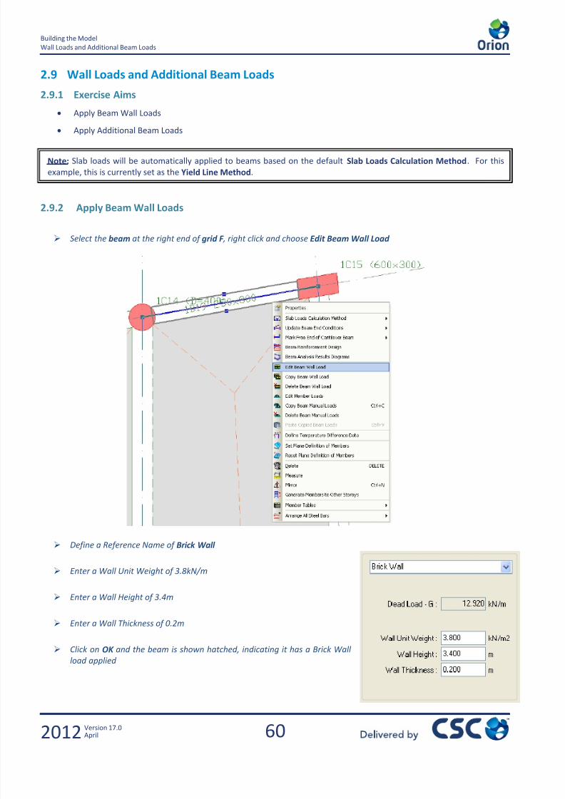
7/22/2019 Standard Training Manual
http://slidepdf.com/reader/full/standard-training-manual 61/286
60
Building the Model
Wall Loads and Additional Beam Loads
2012 Version 17.0April
2.9 Wall Loads and Additional Beam Loads
2.9.1 Exercise Aims
Apply Beam Wall Loads
Apply Additional Beam Loads
2.9.2 Apply Beam Wall Loads
Select the beam at the right end of grid F , right click and choose Edit Beam Wall Load
Define a Reference Name of Brick Wall
Enter a Wall Unit Weight of 3.8kN/m
Enter a Wall Height of 3.4m
Enter a Wall Thickness of 0.2m
Click on OK and the beam is shown hatched, indicating it has a Brick Wall
load applied
Note: Slab loads will be automatically applied to beams based on the default Slab Loads Calculation Method. For this
example, this is currently set as the Yield Line Method.

7/22/2019 Standard Training Manual
http://slidepdf.com/reader/full/standard-training-manual 62/286
61
Building the Model
Wall Loads and Additional Beam Loads
2012 Version 17.0April
To apply the same wall load to the other perimeter beams proceed as follows:
Right mouse click on the same beam again and this time choose Copy Beam Wall Load
Using the Pick icon, select the remaining perimeter beams, remembering to keep the CTRL key held while selecting, so
that each one is added to the existing selection set
When the entire perimeter beams are selected, right click again and this time, choose Paste Copied Beam Loads fromthe menu
When prompted by the below message, click Yes to apply the beam wall load to the beams
All beams will now be hatched in the
same colour to show the loads have
been applied.
Hint?? If you have difficulty selecting the beams try this:
From the Layer Tool Bar at the left edge of the screen click on the Axis Layer Group icon. This will
temporarily switch off the display of the grid lines.
Now use the Pick icon to select the beams
When all the beams are selected remember to switch the grid lines back on by clicking on the Axis Layer
Group icon once more.
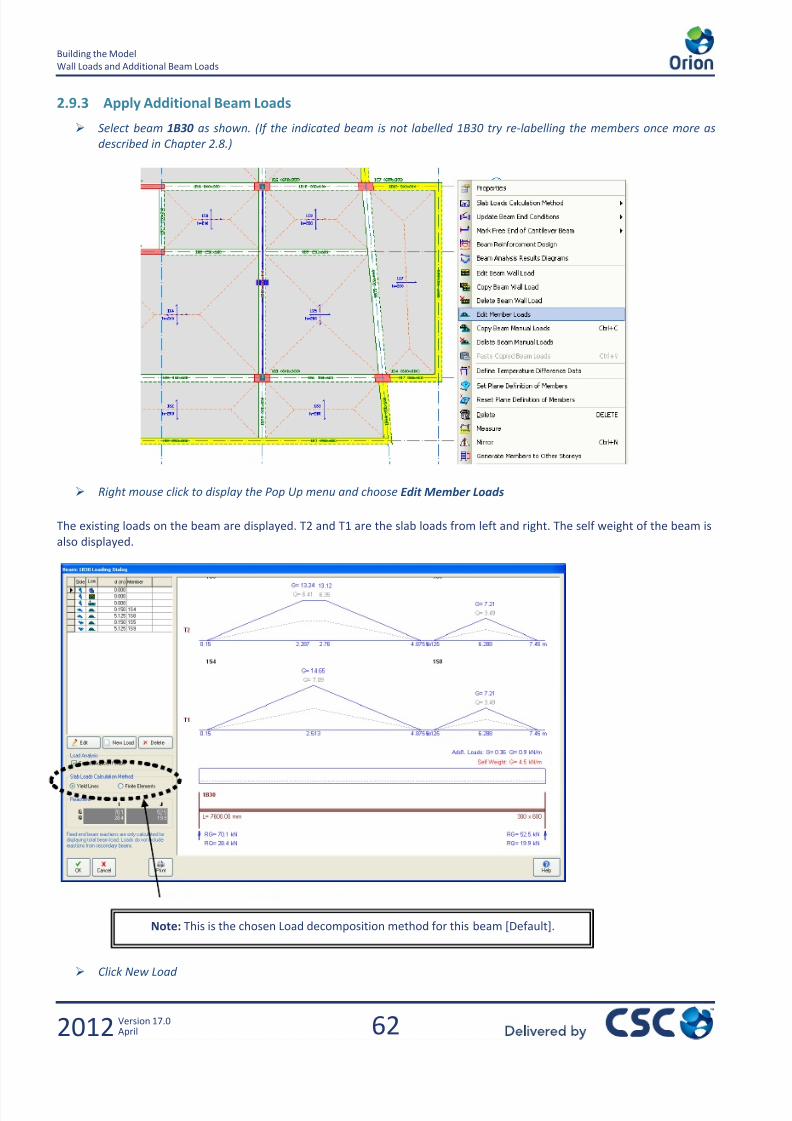
7/22/2019 Standard Training Manual
http://slidepdf.com/reader/full/standard-training-manual 63/286
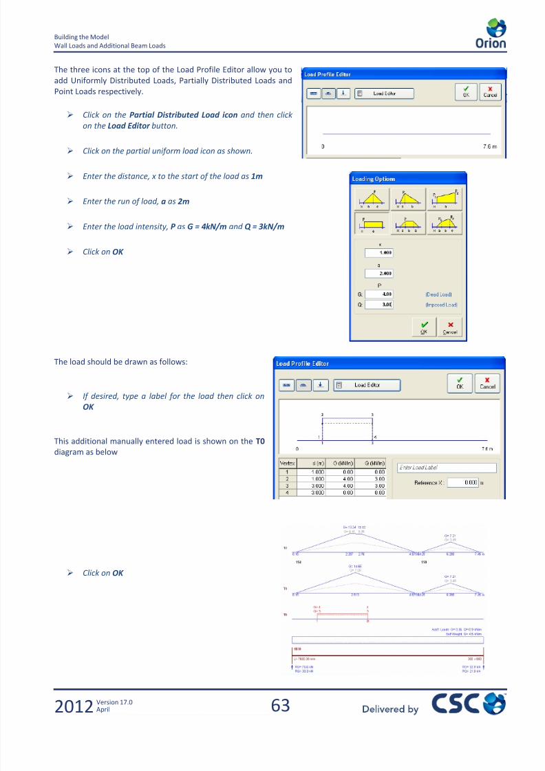
7/22/2019 Standard Training Manual
http://slidepdf.com/reader/full/standard-training-manual 64/286
63
Building the Model
Wall Loads and Additional Beam Loads
2012 Version 17.0April
The three icons at the top of the Load Profile Editor allow you to
add Uniformly Distributed Loads, Partially Distributed Loads and
Point Loads respectively.
Click on the Partial Distributed Load icon and then click
on the Load Editor button.
Click on the partial uniform load icon as shown.
Enter the distance, x to the start of the load as 1m
Enter the run of load, a as 2m
Enter the load intensity, P as G = 4kN/m and Q = 3kN/m
Click on OK
The load should be drawn as follows:
If desired, type a label for the load then click onOK
This additional manually entered load is shown on the T0
diagram as below
Click on OK

7/22/2019 Standard Training Manual
http://slidepdf.com/reader/full/standard-training-manual 65/286
64
Building the Model
Wall Loads and Additional Beam Loads
2012 Version 17.0April
To view the ‘Total Added Loads’ on the beams in the plan view, go
to Settings > View Settings and click on the Beams tab
Left click to tick the box Print Total Added Loads
This will now display the Total Added Loads in the plan view next to every
beam, as shown in the image at the bottom of this page.
You will notice that the settings to control the Beam Hatching are
also found in this view
Set your preferred Hatch Colour by clicking the Select Hatch
Colour button
Try switching between Beams With Wall Loading (to hatch the
perimeter beams) and Beams With User Defined Loading to
hatch beam 1B30.
Click on OK
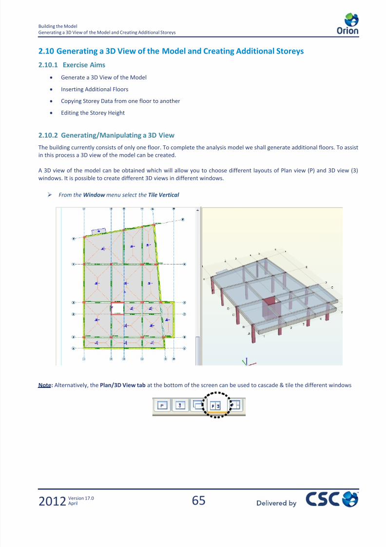
7/22/2019 Standard Training Manual
http://slidepdf.com/reader/full/standard-training-manual 66/286
65
Building the Model
Generating a 3D View of the Model and Creating Additional Storeys
2012 Version 17.0April
2.10 Generating a 3D View of the Model and Creating Additional Storeys
2.10.1 Exercise Aims
Generate a 3D View of the Model
Inserting Additional Floors
Copying Storey Data from one floor to another
Editing the Storey Height
2.10.2 Generating/Manipulating a 3D View
The building currently consists of only one floor. To complete the analysis model we shall generate additional floors. To assist
in this process a 3D view of the model can be created.
A 3D view of the model can be obtained which will allow you to choose different layouts of Plan view (P) and 3D view (3)
windows. It is possible to create different 3D views in different windows.
From the Window menu select the Tile Vertical
Note: Alternatively, the Plan/3D View tab at the bottom of the screen can be used to cascade & tile the different windows

7/22/2019 Standard Training Manual
http://slidepdf.com/reader/full/standard-training-manual 67/286
66
Building the Model
Generating a 3D View of the Model and Creating Additional Storeys
2012 Version 17.0April
The 3D View can be manipulated in a number of ways:
Left click on the 3D View window to make it active
Zoom - Scroll the scroll wheel on your mouse and will zoom in to the centre of the model.
Pan - Depress the scroll wheel on your mouse and then moving the cursor around the screen.
Rotate - Hold down the right mouse button and moving the cursor around the screen. The model will rotate about its centre
point.
There is also a toolbar at the bottom of the 3D view that allows much more manipulation of the view.
You can also model in 3D by being able to Insert, Edit and Delete elements in the same manner as in the 2D view.
Plan
View
Filters
Zoom
Functions
Window
Views
Regen
View
Settings
Animation/
Save Image
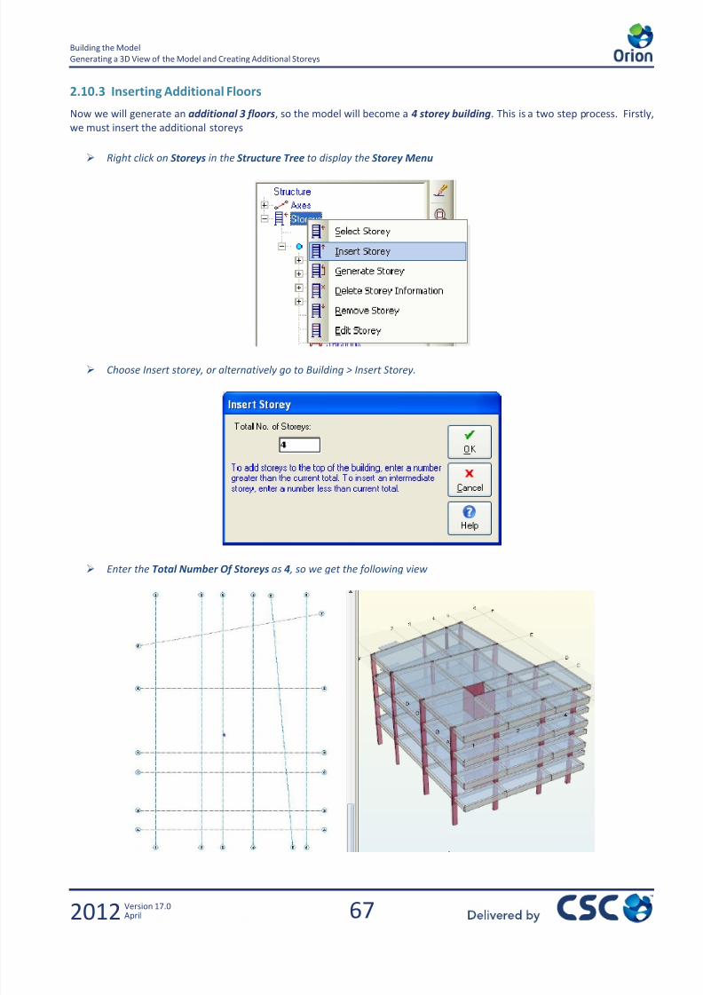
7/22/2019 Standard Training Manual
http://slidepdf.com/reader/full/standard-training-manual 68/286
67
Building the Model
Generating a 3D View of the Model and Creating Additional Storeys
2012 Version 17.0April
2.10.3 Inserting Additional Floors
Now we will generate an additional 3 floors, so the model will become a 4 storey building. This is a two step process. Firstly,
we must insert the additional storeys
Right click on Storeys in the Structure Tree to display the Storey Menu
Choose Insert storey, or alternatively go to Building > Insert Storey.
Enter the Total Number Of Storeys as 4 , so we get the following view

7/22/2019 Standard Training Manual
http://slidepdf.com/reader/full/standard-training-manual 69/286
68
Building the Model
Generating a 3D View of the Model and Creating Additional Storeys
2012 Version 17.0April
2.10.4 Copying Floor Data to Other Floors
The model now has 4 storeys, but as can be seen, it does not contain any members in
the plan view.
Right click on Storeys in the Structure Tree to display the Storey Menu and
select the option Generate storey (or go to Building > Generate Storey ) sothe Generate Storey window appears
Highlight St01 as the Source Storey and then St04 as the Target Storey.
Then click on OK .
Once you get the message ‘Process Completed’ at the bottom of this window,
select Close
From the Structure Tree you will see that St01 & St04 have a circle mark next to them but St02 & St03 don’t have this mark.
Floors with a mark are classed as ‘Unique’ and have their own storey information (beams,columns, walls etc). Floors without a mark next to them are classed as ‘Duplicates’ and are
automatically made identical to the first Unique Storey directly above it. Therefore, only
‘Unique’ storeys can be edited. Hence storeys St02 & St03 are duplicates of St04. This is
highlighted by the Storey Reference in brackets.
Whatever changes are made to the Unique Floor will be carried through its Duplicates.
Therefore, if we were to edit St04 now, the same changes would be applied to the Duplicates St03 and St02.
We want to edit St04 (the roof) but keep the other floors below it the same as they are now. Therefore, we need to first
generate the same storey information from the St04 to St03 then modify the 4th
storey accordingly.
So we can do this as follows:
Right click on Storeys in the Structure Tree to display the Storey Menu and select the option Generate storey .
Ensure that the source storey is St04 and the Target Storey St03 then choose OK
Once the process is complete, click Close
From the Structure Tree you will see that St03 now has a circle mark next to it indicating that
it is a unique and editable floor, as are St01 and St04.
St02 cannot be edited, as it is identical to St03.
2.10.5 Moving between Storeys
The current storey displayed in the plan view will be shown in bold on the Storey menu in the Structure Tree. To change to a
different storey, simply double click on it in the Structure Tree.
If you are not currently viewing storey 4, double click on Storey: St04 so that it is shown in bold (as shown on the
right)

7/22/2019 Standard Training Manual
http://slidepdf.com/reader/full/standard-training-manual 70/286
69
Building the Model
Generating a 3D View of the Model and Creating Additional Storeys
2012 Version 17.0April
2.10.6 Editing the Roof
Select the Slab icon or from the Pull Down menu select Member > Slab.
Select the Slab Type to be 1 and ensure the thickness is 200mm and the cover 25mm.
Then enter the slab where the lift wall is at Grid 2-3/C-D
So your screen should look as follows:
2.10.7 Editing the Storey Height
We will now edit the storey height as currently each floor is 3300mm high based on the 1st
storey generated earlier.
Select Edit Storey from the storey menu or by going to Building > Edit Storey so the Edit Storey dialog box appears as
shown below.
To change a floor height, click in the cell for h(mm) at the desired storey, St01

7/22/2019 Standard Training Manual
http://slidepdf.com/reader/full/standard-training-manual 71/286
70
Building the Model
Generating a 3D View of the Model and Creating Additional Storeys
2012 Version 17.0April
Change the current value of 3300 to be 4000 . Click outside the cell and you should notice the values in the Level
column have changed as shown below.
1st
Storey Bottom Level – This is effectively the Z co-ordinate for ST00. This does not affect the storey heights of any level
and is only used to calculate the reference level for each floor (shown in the ‘Level’ column in the table above).
Foundation Level –This is the length of the column below the datum level (St00), by Default 1100m
2.10.8 Specifying Imposed Load Reductions for Each Floor
The Edit Storey dialog is used to apply imposed load reductions
to a model. You can also specify whether you want to consider
the roof level.
Tick the option to Consider Roof Level as Adequate Storey
for Live Load Reductions
Click the Apply button to apply the appropriate Imposed
Load Reduction factors to each level
Click OK
7/22/2019 Standard Training Manual
http://slidepdf.com/reader/full/standard-training-manual 72/286

7/22/2019 Standard Training Manual
http://slidepdf.com/reader/full/standard-training-manual 73/286
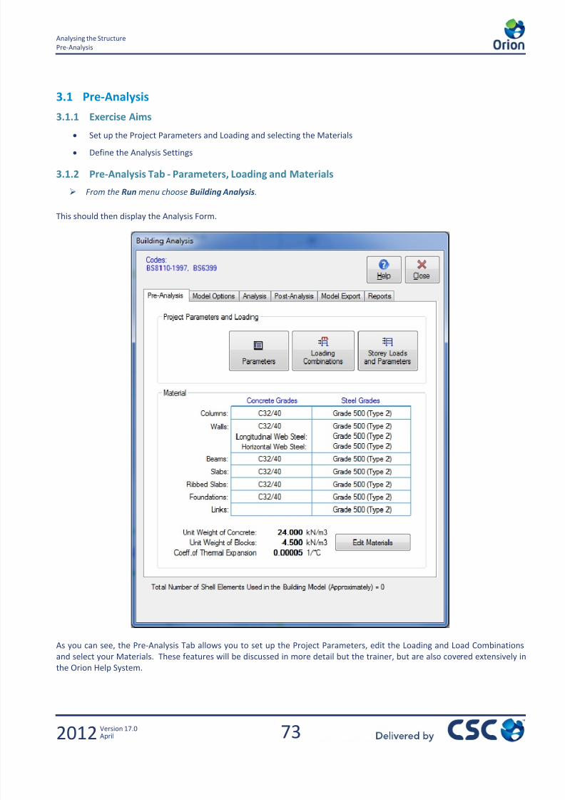
7/22/2019 Standard Training Manual
http://slidepdf.com/reader/full/standard-training-manual 74/286
73
Analysing the Structure
Pre-Analysis
2012 Version 17.0April
3.1 Pre-Analysis
3.1.1 Exercise Aims
Set up the Project Parameters and Loading and selecting the Materials
Define the Analysis Settings
3.1.2 Pre-Analysis Tab - Parameters, Loading and Materials
From the Run menu choose Building Analysis.
This should then display the Analysis Form.
As you can see, the Pre-Analysis Tab allows you to set up the Project Parameters, edit the Loading and Load Combinations
and select your Materials. These features will be discussed in more detail but the trainer, but are also covered extensively in
the Orion Help System.

7/22/2019 Standard Training Manual
http://slidepdf.com/reader/full/standard-training-manual 75/286
74
Analysing the Structure
Pre-Analysis
2012 Version 17.0April
The Parameters button allows the user to set/modify the Project Parameters. These include:
Codes: Select which design codes you are working to
Lateral Loading: Decide how your Notional Horizontal Forces are calculated
Lateral Drift: Decide if the structure is braced or unbraced
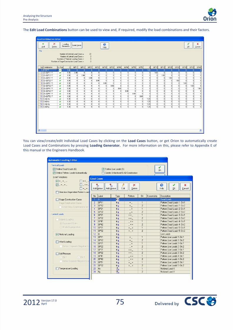
7/22/2019 Standard Training Manual
http://slidepdf.com/reader/full/standard-training-manual 76/286

7/22/2019 Standard Training Manual
http://slidepdf.com/reader/full/standard-training-manual 77/286
76
Analysing the Structure
Pre-Analysis
2012 Version 17.0April
The Edit Storey Loads button can be used to view and, if required, modify the lateral load cases applied at each storey. You
can also view the Mass and co-ordinates for the Centre of Gravity for each level. The notional lateral loads are calculated
automatically once the Building Analysis is complete.
The Edit Materials button can be used to view the concrete and steel grades selected for each member group and the steel
bars available for the design for each element group. You can also specify the Unit Weight of Concrete and Blocks and set
the Coefficient of Thermal Expansion.
Click the Edit Materials button on the Pre-Analysis Tab so the following screen appears.
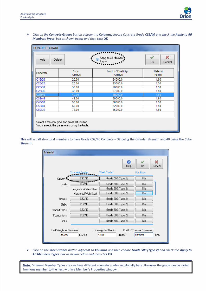
7/22/2019 Standard Training Manual
http://slidepdf.com/reader/full/standard-training-manual 78/286

7/22/2019 Standard Training Manual
http://slidepdf.com/reader/full/standard-training-manual 79/286
78
Analysing the Structure
Pre-Analysis
2012 Version 17.0April
This will set all structural members to have Grade 500 (Type 2) Steel for their reinforcement.
Check that you have the unit weight of concrete set to 24kN/m3 before proceeding.
Click the Bar Sizes button adjacent to Columns.
You will notice some bars have been selected by default. Bars can be unselected by clicking on them to remove the tick
(similarly click to select).
Note: If you do not select a particular bar size here, that size will NOT be available for selection in the design processlater. For example, if you only ticked H16 in this window, only H16s could be used to design the Columns later.
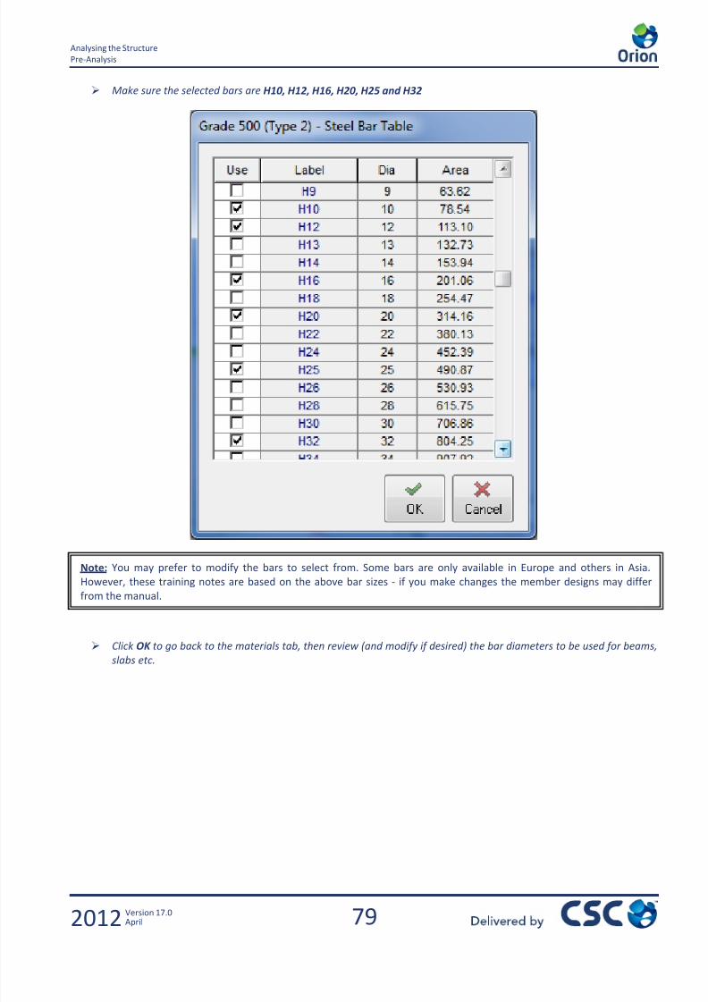
7/22/2019 Standard Training Manual
http://slidepdf.com/reader/full/standard-training-manual 80/286
79
Analysing the Structure
Pre-Analysis
2012 Version 17.0April
Make sure the selected bars are H10, H12, H16, H20, H25 and H32
Click OK to go back to the materials tab, then review (and modify if desired) the bar diameters to be used for beams,
slabs etc.
Note: You may prefer to modify the bars to select from. Some bars are only available in Europe and others in Asia.
However, these training notes are based on the above bar sizes - if you make changes the member designs may differ
from the manual.
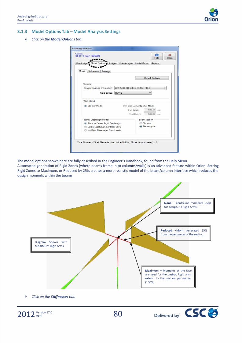
7/22/2019 Standard Training Manual
http://slidepdf.com/reader/full/standard-training-manual 81/286
80
Analysing the Structure
Pre-Analysis
2012 Version 17.0April
3.1.3 Model Options Tab – Model Analysis Settings
Click on the Model Options tab
The model options shown here are fully described in the Engineer’s Handbook, found from the Help Menu.
Automated generation of Rigid Zones (where beams frame in to columns/walls) is an advanced feature within Orion. Setting
Rigid Zones to Maximum, or Reduced by 25% creates a more realistic model of the beam/column interface which reduces the
design moments within the beams.
Click on the Stiffnesses tab.
None – Centreline moments used
for design. No Rigid Arms.
Reduced –Mom generated 25%
from the perimeter of the section
Maximum – Moments at the face
are used for the design. Rigid arms
extend to the section perimeters
(100%).
Diagram Shown with
MAXIMUM Rigid Arms

7/22/2019 Standard Training Manual
http://slidepdf.com/reader/full/standard-training-manual 82/286
81
Analysing the Structure
Pre-Analysis
2012 Version 17.0April
On this page, the engineer can globally adjust the properties to be used for each member type.
No changes will be made, click on Settings tab.
Total Hor. Drift Limit – This check is for the maximum total allowable displacement, which is checked at every storey level.
12000mm * 0.0010 = 12mm
Relative Hor. Drift Limit – This check is in accordance with BS 8110: Part 2 and is the maximum relative displacementbetween each storey. 3300mm * 0.002 = 6.6mm
These checks are performed for the NHF’s, Nx and Ny
Tick the option Use Decomposed Beam Loads
Note: For flat slab models there is an option to use undecomposed slab loads for the notional horizontal load calculation.
See later notes.
Note: The torsional stiffness factor has been set to 0.01 for the beams to prevent significant torsions from developing.

7/22/2019 Standard Training Manual
http://slidepdf.com/reader/full/standard-training-manual 83/286

7/22/2019 Standard Training Manual
http://slidepdf.com/reader/full/standard-training-manual 84/286
83
Analysing the Structure
Performing the Analysis
2012 Version 17.0April
Choose All Storeys and then click on the Ok button.
Note: Even if this reports no errors, it doesn’t guarantee that the building is modelled correctly. There can be other problems
in the model that are not picked up by the validity checking process.
Assuming that no errors are reported, Cancel the dialog
During the Building Analysis, the Beam Load Calculations (All Storeys) are completed (based upon your loading method –
currently Yield Line). The slab loads are distributed onto the supporting beams; all the load data is assessed; the weights and
mass centres of each storey are calculated and any notional lateral loads are determined.
After analysis it is then possible to automatically perform Column/Wall Reinforcement Design and Beam Reinforcement
Design for all members in the building.
Make sure Column/Wall Reinforcement Design and Beam Reinforcement Design are not checked before clicking on
Start to begin the building analysis process.
The Beam Load Calculations commence and a warning message should be displayed.
Click Yes and the analysis process continues and then OK when the Analysis has completed.
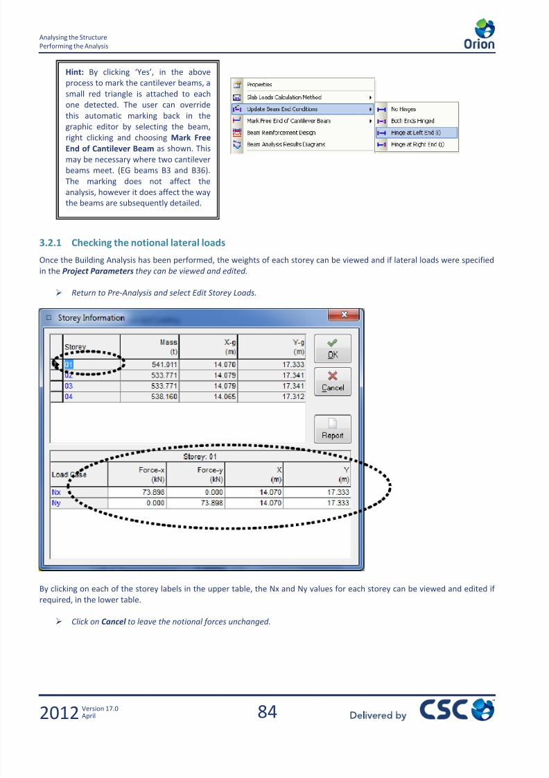
7/22/2019 Standard Training Manual
http://slidepdf.com/reader/full/standard-training-manual 85/286
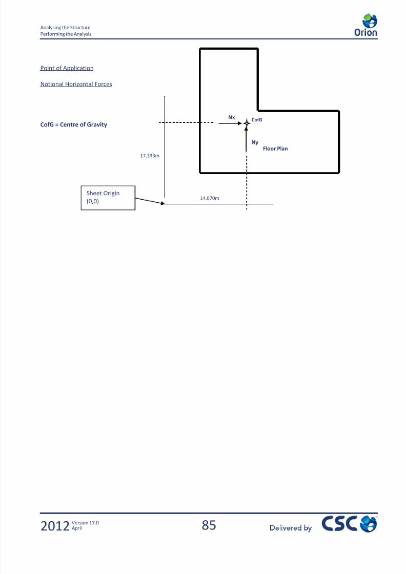
7/22/2019 Standard Training Manual
http://slidepdf.com/reader/full/standard-training-manual 86/286
85
Analysing the Structure
Performing the Analysis
2012 Version 17.0April
Point of Application
Notional Horizontal Forces
CofG = Centre of GravityCofG
Floor PlanNy
Nx
Sheet Origin(0,0)14.070m
17.333m

7/22/2019 Standard Training Manual
http://slidepdf.com/reader/full/standard-training-manual 87/286
86
Analysing the Structure
Post-Analysis
2012 Version 17.0April
3.3 Post-Analysis
3.3.1 Cross Checking the Analysis Result
An important cross check on the validity of the analysis is the Axial Load Comparison Report . This report sums all of the deadand live loads applied at each storey and displays the axial forces in the columns and shear walls. These values should equate
to each other (within a few percent). If they do not the reason for the discrepancy should be investigated.
Go back to the Analysis tab
Select Axial Load Comparison Report
The total “SUM OF APPLIED LOADS (Using Un-Decomposed Slab Loads)” values should be similar to those from the
Decomposed Slab Loads table.
Provided that any difference between the un-decomposed and the decomposed values can be accounted for, the Total
Decomposed Applied Dead Load should be compared with the Total Delta G value from the “BUILDING ANALYSISCOLUMN/WALL AXIAL LOADS” table. Similarly, the Total Decomposed Live Load should then be compared with the Total
Delta Q value.
Any significant differences in these values also have to be able to be accounted for.
If required the report can be printed, or it can be saved for later inclusion in a batch print out of all reports created by the
program.
Click on Save See following page for an example of the Axial Load Comparison report
Summary – For Beam and Column Construction
CHECK 1
Sum of Un-decomposed Slab Loads ~ Sum of Decomposed Slab Loads
CHECK 2
Total Decomposed Applied Dead Load ~ Total Delta G
CHECK 3
Total Decomposed Applied Live Load ~ Total Delta Q
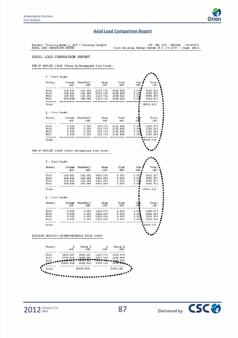
7/22/2019 Standard Training Manual
http://slidepdf.com/reader/full/standard-training-manual 88/286

7/22/2019 Standard Training Manual
http://slidepdf.com/reader/full/standard-training-manual 89/286
88
Analysing the Structure
Post-Analysis
2012 Version 17.0April
3.3.2 Model and Analysis Results Display
The Analysis results can also be viewed graphically. Various effects can be displayed and the results can be filtered by axis
and by storey.
Click on the Post-Analysis tab
Click Model and Analysis Results Display
If too many labels are displayed the screen can appear cluttered as shown above. However, using the various drop-down
filter buttons and the view settings, you can create something more meaningful.

7/22/2019 Standard Training Manual
http://slidepdf.com/reader/full/standard-training-manual 90/286
89
Analysing the Structure
Post-Analysis
2012 Version 17.0April
Click the various filter buttons to create different views. You can use the ribbons to choose what you want to show,
and then the button can be toggled on and off.
Above from the Elements ribbon we have selected the Nodal Points and the Frame Elements filters.
By clicking on the General Ribbon and selecting the Filters button, you can filter by storeys, axes and member type, as shown
above.
You can also do a Search for specific nodes, frame elements or shell elements by clicking on the binoculars icon, to the left of
the filters button, as shown below.
A large arrow will point at the item you have searched for. This is useful if the Building Analysis reports conditions with
certain nodes.

7/22/2019 Standard Training Manual
http://slidepdf.com/reader/full/standard-training-manual 91/286
90
Analysing the Structure
Post-Analysis
2012 Version 17.0April
There are further filtering and setting options found in the View Settings window, situated on the left hand side of the
screen:
Below is a view of the model showing the displacement, using the Displacements filter from the Results Ribbon. The X values
have also been displayed, and the displacement scale has been increased.

7/22/2019 Standard Training Manual
http://slidepdf.com/reader/full/standard-training-manual 92/286
91
Analysing the Structure
Post-Analysis
2012 Version 17.0April
This next view shows the frame loads and values for storey 4 only.
All results displayed are based on the specific Load Case or Load Combination selected in the Loading Window on the right
hand side of the scree drop down menu.

7/22/2019 Standard Training Manual
http://slidepdf.com/reader/full/standard-training-manual 93/286
92
Analysing the Structure
Post-Analysis
2012 Version 17.0April
3.3.3 Analysis Output Reports (for information only)
The next stage is to prepare a report of the analysis results.
Select Analysis Results Report so the following dialog box appears
Expand Storey 1 and highlight Columns and Walls by holding down CTRL as shown
Click on the button to transfer all the columns and walls to the right hand side
Click Next and on the next screen select Structural Members
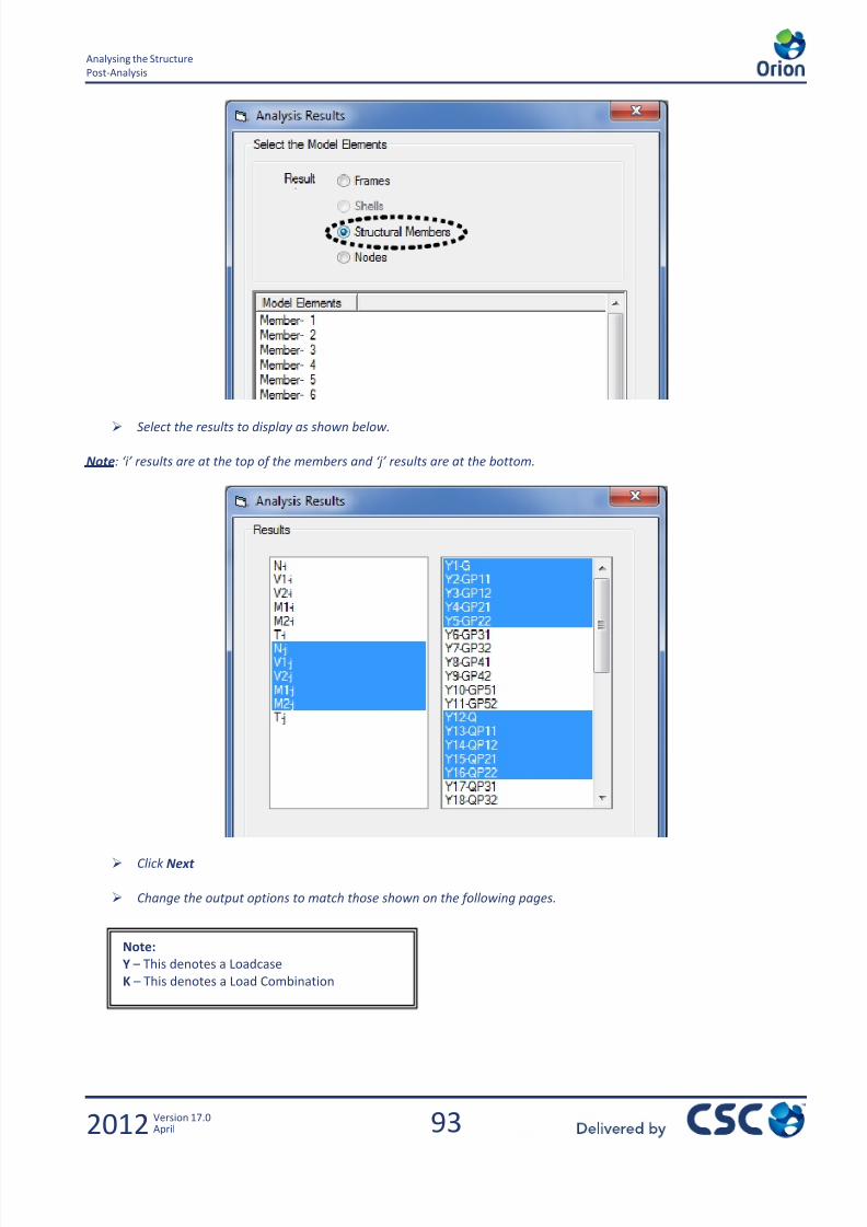
7/22/2019 Standard Training Manual
http://slidepdf.com/reader/full/standard-training-manual 94/286
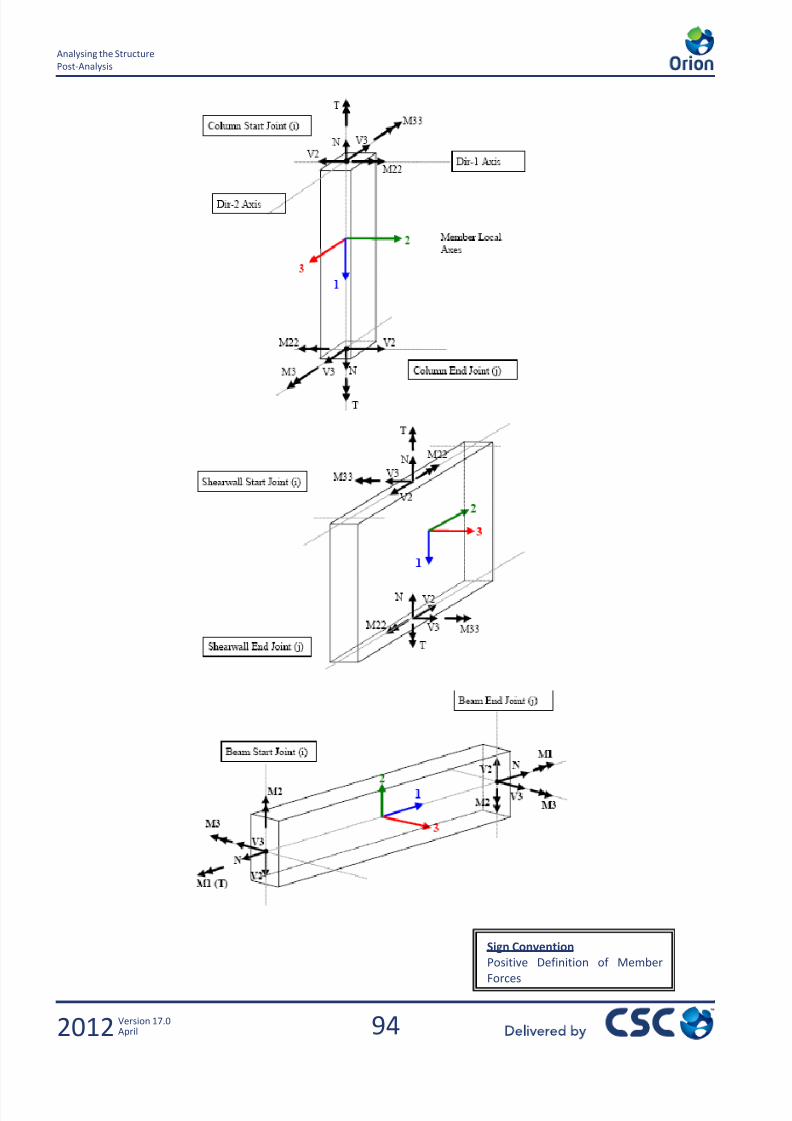
7/22/2019 Standard Training Manual
http://slidepdf.com/reader/full/standard-training-manual 95/286
94
Analysing the Structure
Post-Analysis
2012 Version 17.0April
Sign Convention
Positive Definition of Member
Forces
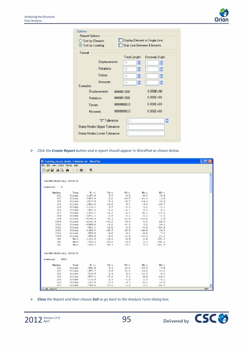
7/22/2019 Standard Training Manual
http://slidepdf.com/reader/full/standard-training-manual 96/286

7/22/2019 Standard Training Manual
http://slidepdf.com/reader/full/standard-training-manual 97/286
96
Analysing the Structure
Post-Analysis
2012 Version 17.0April
From the Analysis Form, a formatted version of the report could be generated by selecting “Structural Member Results” from
the Output Reports drop down menu. This could then be printed directly or saved to a file using the commands on the File
menu.
Apart from the Building Analysis Results, various other reports are also available.
Click on the Model Export tab
This area allows you to export your Orion model to various other programs – such as S-Frame - so you can investigate it
further without having to create a new model for each program.
Click on the Reports tab.
As we have seen, the analysis results report is available on the Post-Analysis tab, however all of the other detailed output
reports are available from here, For example:
Pre-analysis checks report: - a basic summary of the model input.
Post Analysis Checks Report: - the horizontal displacement (drift) checks (Total and Relative).
Analysis Model Echo Report:- the full analysis input data file.
Storey Displacements Report : Orion calculates the displacements in the x and y directions and torsion for each load
combination for each storey.
Sway Classification Report: This report is based upon ACI code recommendations, and is not applicable if braced conditions
have been manually amended. This option should only be used with cross reference to the ACI code.
Beam Load Analysis Report : contains the beam loads.
Each of these reports can be printed, or saved for later inclusion in a batch print out of all reports created by the program.
They can also be exported to a variety of different file formats.

7/22/2019 Standard Training Manual
http://slidepdf.com/reader/full/standard-training-manual 98/286
97
Beam Reinforcement
Post-Analysis
2012 Version 17.0April
4.0 Beam Reinforcement
Beam Reinforcement Design

7/22/2019 Standard Training Manual
http://slidepdf.com/reader/full/standard-training-manual 99/286
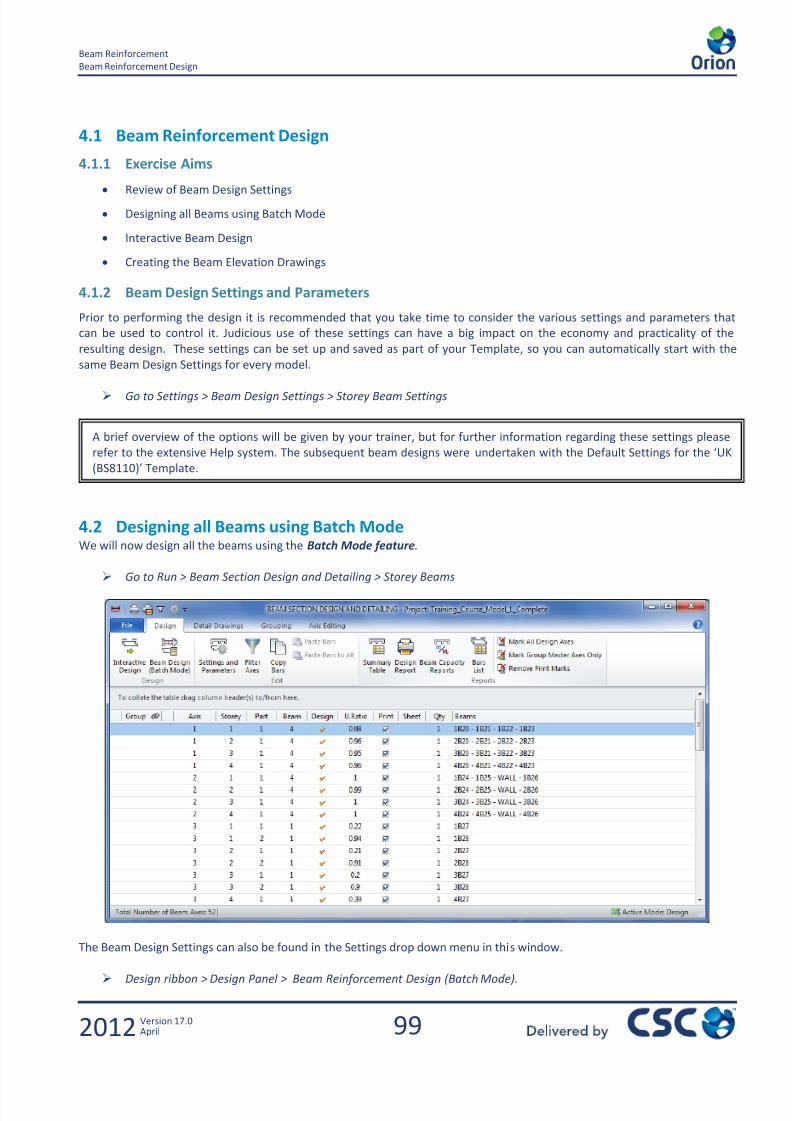
7/22/2019 Standard Training Manual
http://slidepdf.com/reader/full/standard-training-manual 100/286
99
Beam Reinforcement
Beam Reinforcement Design
2012 Version 17.0April
4.1 Beam Reinforcement Design
4.1.1 Exercise Aims
Review of Beam Design Settings
Designing all Beams using Batch Mode
Interactive Beam Design
Creating the Beam Elevation Drawings
4.1.2 Beam Design Settings and Parameters
Prior to performing the design it is recommended that you take time to consider the various settings and parameters that
can be used to control it. Judicious use of these settings can have a big impact on the economy and practicality of the
resulting design. These settings can be set up and saved as part of your Template, so you can automatically start with the
same Beam Design Settings for every model.
Go to Settings > Beam Design Settings > Storey Beam Settings
4.2 Designing all Beams using Batch ModeWe will now design all the beams using the Batch Mode feature.
Go to Run > Beam Section Design and Detailing > Storey Beams
The Beam Design Settings can also be found in the Settings drop down menu in this window.
Design ribbon > Design Panel > Beam Reinforcement Design (Batch Mode).
A brief overview of the options will be given by your trainer, but for further information regarding these settings please
refer to the extensive Help system. The subsequent beam designs were undertaken with the Default Settings for the ‘UK
(BS8110)’ Template.

7/22/2019 Standard Training Manual
http://slidepdf.com/reader/full/standard-training-manual 101/286

7/22/2019 Standard Training Manual
http://slidepdf.com/reader/full/standard-training-manual 102/286
101
Beam Reinforcement
Designing all Beams using Batch Mode
2012 Version 17.0April
4.2.1 Graphical Review of Passing / Failing Members
It is possible to review the design status of all members graphically. This is done by clicking on the Design Status tab located
at the bottom of the Structure tree view.
Close the beam design summary and click the Design Status tab as shown.
Any failing beams would be highlighted in red
Select Run > Beam Section Design and Detailing > Storey Beams to redisplay the beam design summary.
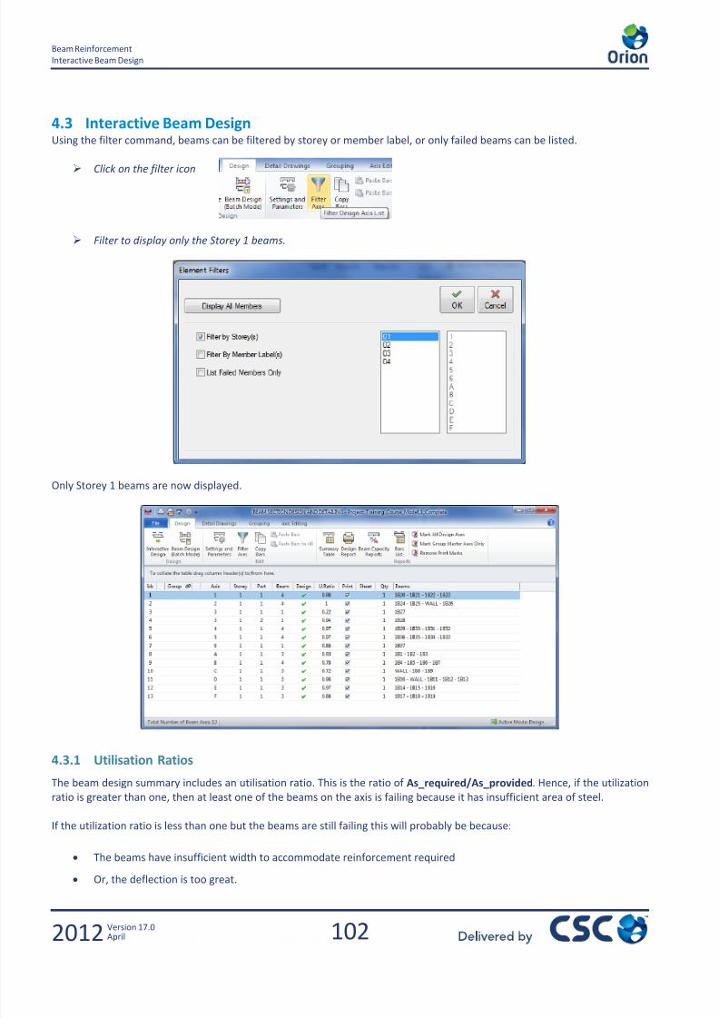
7/22/2019 Standard Training Manual
http://slidepdf.com/reader/full/standard-training-manual 103/286
102
Beam Reinforcement
Interactive Beam Design
2012 Version 17.0April
4.3 Interactive Beam DesignUsing the filter command, beams can be filtered by storey or member label, or only failed beams can be listed.
Click on the filter icon
Filter to display only the Storey 1 beams.
Only Storey 1 beams are now displayed.
4.3.1 Utilisation Ratios
The beam design summary includes an utilisation ratio. This is the ratio of As_required/As_provided. Hence, if the utilization
ratio is greater than one, then at least one of the beams on the axis is failing because it has insufficient area of steel.
If the utilization ratio is less than one but the beams are still failing this will probably be because:
The beams have insufficient width to accommodate reinforcement required
Or, the deflection is too great.
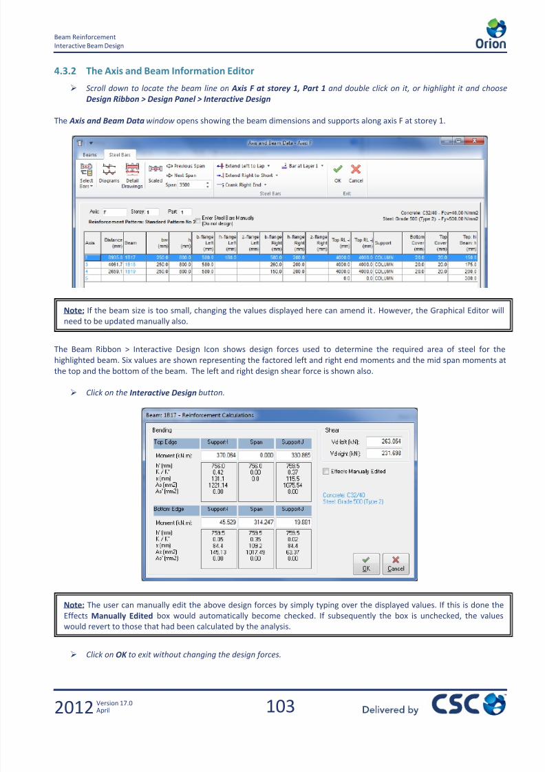
7/22/2019 Standard Training Manual
http://slidepdf.com/reader/full/standard-training-manual 104/286
103
Beam Reinforcement
Interactive Beam Design
2012 Version 17.0April
4.3.2 The Axis and Beam Information Editor
Scroll down to locate the beam line on Axis F at storey 1, Part 1 and double click on it, or highlight it and choose
Design Ribbon > Design Panel > Interactive Design
The Axis and Beam Data window opens showing the beam dimensions and supports along axis F at storey 1.
The Beam Ribbon > Interactive Design Icon shows design forces used to determine the required area of steel for the
highlighted beam. Six values are shown representing the factored left and right end moments and the mid span moments at
the top and the bottom of the beam. The left and right design shear force is shown also.
Click on the Interactive Design button.
Click on OK to exit without changing the design forces.
Note: If the beam size is too small, changing the values displayed here can amend it . However, the Graphical Editor will
need to be updated manually also.
Note: The user can manually edit the above design forces by simply typing over the displayed values. If this is done the
Effects Manually Edited box would automatically become checked. If subsequently the box is unchecked, the values
would revert to those that had been calculated by the analysis.

7/22/2019 Standard Training Manual
http://slidepdf.com/reader/full/standard-training-manual 105/286
104
Beam Reinforcement
Interactive Beam Design
2012 Version 17.0April
4.3.3 The Reinforcement Data Screen
To review and modify the reinforcement provided by the batch design, click Select Bars. This should then display the
Reinforcement Data screen similar to below:
Any figures in red indicate a problem. In this case there aren’t any problems. However, if the number of top span bars are
reduced for 1B18, a spacing issue is highlighted in red, as shown above. Settings that can be adjusted to try to obtain a
design include number of bars, bar diameter, lap lengths, cranks and layers. These will be discussed further in a short while.
4.3.4 Beam Detail Drawings
The above bar pattern is referred to as Standard Pattern 2. To see the beam detail drawing for it, click on the Detail Drawing
button.
Standard Pattern 2
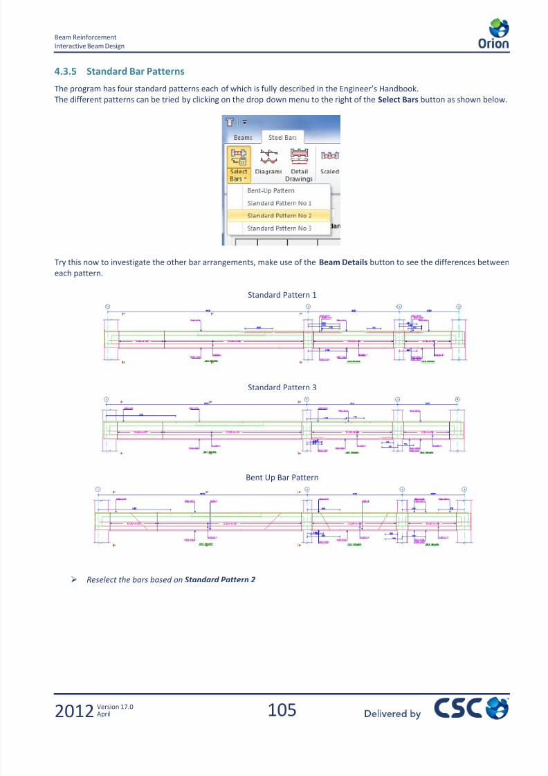
7/22/2019 Standard Training Manual
http://slidepdf.com/reader/full/standard-training-manual 106/286
105
Beam Reinforcement
Interactive Beam Design
2012 Version 17.0April
4.3.5 Standard Bar Patterns
The program has four standard patterns each of which is fully described in the Engineer’s Handbook.
The different patterns can be tried by clicking on the drop down menu to the right of the Select Bars button as shown below.
Try this now to investigate the other bar arrangements, make use of the Beam Details button to see the differences betweeneach pattern.
Standard Pattern 1
Standard Pattern 3
Bent Up Bar Pattern
Reselect the bars based on Standard Pattern 2
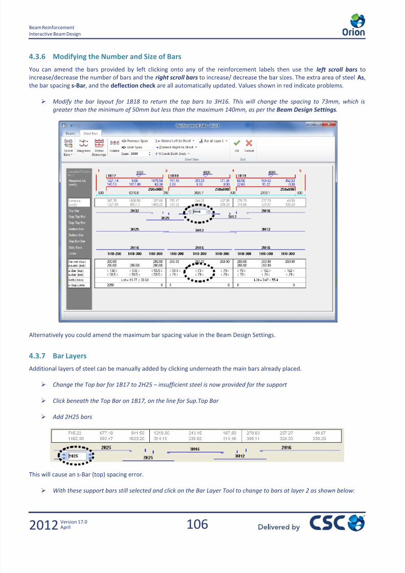
7/22/2019 Standard Training Manual
http://slidepdf.com/reader/full/standard-training-manual 107/286
106
Beam Reinforcement
Interactive Beam Design
2012 Version 17.0April
4.3.6 Modifying the Number and Size of Bars
You can amend the bars provided by left clicking onto any of the reinforcement labels then use the left scroll bars to
increase/decrease the number of bars and the right scroll bars to increase/ decrease the bar sizes. The extra area of steel As,
the bar spacing s-Bar, and the deflection check are all automatically updated. Values shown in red indicate problems.
Modify the bar layout for 1B18 to return the top bars to 3H16. This will change the spacing to 73mm, which is
greater than the minimum of 50mm but less than the maximum 140mm, as per the Beam Design Settings.
Alternatively you could amend the maximum bar spacing value in the Beam Design Settings.
4.3.7 Bar Layers
Additional layers of steel can be manually added by clicking underneath the main bars already placed.
Change the Top bar for 1B17 to 2H25 – insufficient steel is now provided for the support
Click beneath the Top Bar on 1B17, on the line for Sup.Top Bar
Add 2H25 bars
This will cause an s-Bar (top) spacing error.
With these support bars still selected and click on the Bar Layer Tool to change to bars at layer 2 as shown below:

7/22/2019 Standard Training Manual
http://slidepdf.com/reader/full/standard-training-manual 108/286
107
Beam Reinforcement
Interactive Beam Design
2012 Version 17.0April
Bars placed in layer 2 are shown as dotted lines as shown.
Shown below is the amended beam detail.
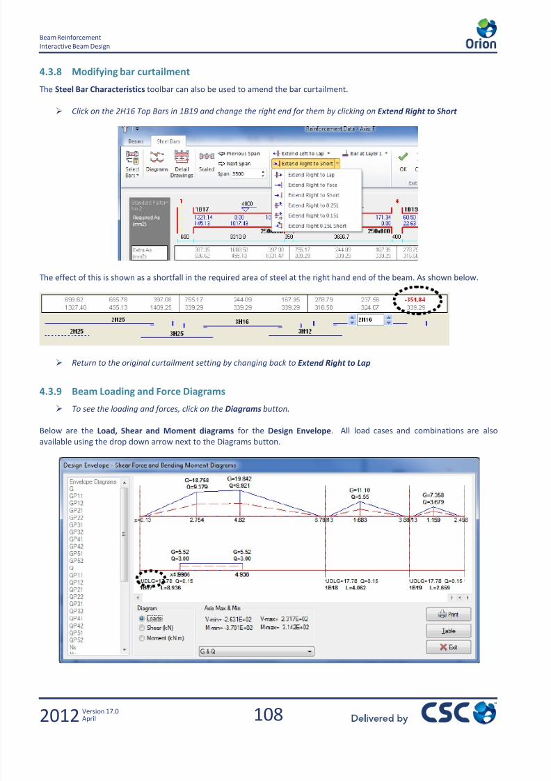
7/22/2019 Standard Training Manual
http://slidepdf.com/reader/full/standard-training-manual 109/286
108
Beam Reinforcement
Interactive Beam Design
2012 Version 17.0April
4.3.8 Modifying bar curtailment
The Steel Bar Characteristics toolbar can also be used to amend the bar curtailment.
Click on the 2H16 Top Bars in 1B19 and change the right end for them by clicking on Extend Right to Short
The effect of this is shown as a shortfall in the required area of steel at the right hand end of the beam. As shown below.
Return to the original curtailment setting by changing back to Extend Right to Lap
4.3.9 Beam Loading and Force Diagrams
To see the loading and forces, click on the Diagrams button.
Below are the Load, Shear and Moment diagrams for the Design Envelope. All load cases and combinations are also
available using the drop down arrow next to the Diagrams button.
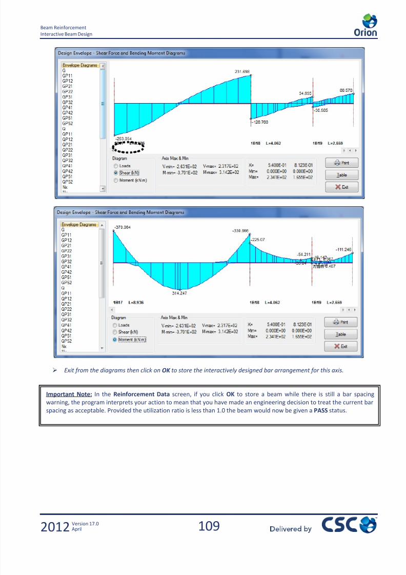
7/22/2019 Standard Training Manual
http://slidepdf.com/reader/full/standard-training-manual 110/286
109
Beam Reinforcement
Interactive Beam Design
2012 Version 17.0April
Exit from the diagrams then click on OK to store the interactively designed bar arrangement for this axis.
Important Note: In the Reinforcement Data screen, if you click OK to store a beam while there is still a bar spacingwarning, the program interprets your action to mean that you have made an engineering decision to treat the current bar
spacing as acceptable. Provided the utilization ratio is less than 1.0 the beam would now be given a PASS status.
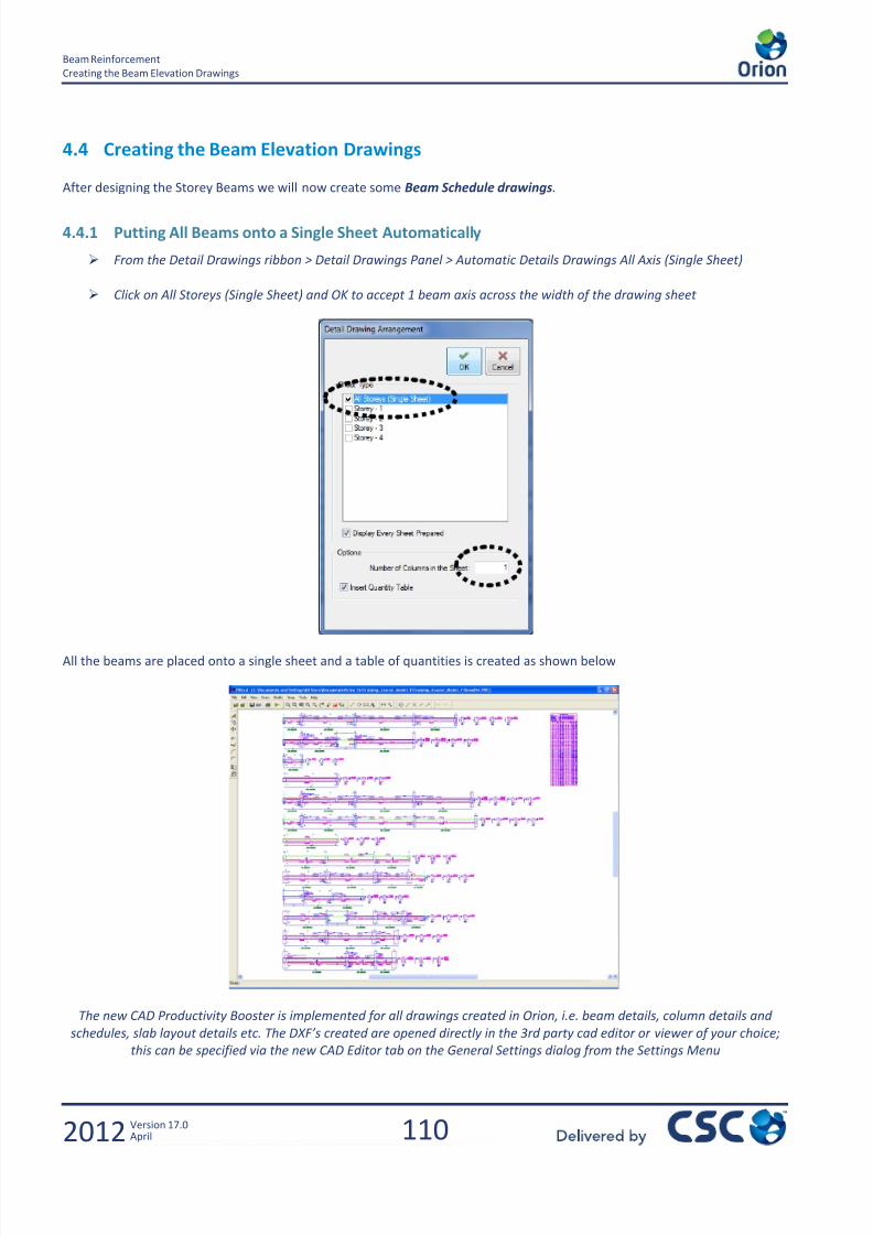
7/22/2019 Standard Training Manual
http://slidepdf.com/reader/full/standard-training-manual 111/286
110
Beam Reinforcement
Creating the Beam Elevation Drawings
2012 Version 17.0April
4.4 Creating the Beam Elevation Drawings
After designing the Storey Beams we will now create some Beam Schedule drawings.
4.4.1 Putting All Beams onto a Single Sheet Automatically
From the Detail Drawings ribbon > Detail Drawings Panel > Automatic Details Drawings All Axis (Single Sheet)
Click on All Storeys (Single Sheet) and OK to accept 1 beam axis across the width of the drawing sheet
All the beams are placed onto a single sheet and a table of quantities is created as shown below
The new CAD Productivity Booster is implemented for all drawings created in Orion, i.e. beam details, column details and
schedules, slab layout details etc. The DXF’s created are opened directly in the 3rd party cad editor or viewer of your choice;
this can be specified via the new CAD Editor tab on the General Settings dialog from the Settings Menu

7/22/2019 Standard Training Manual
http://slidepdf.com/reader/full/standard-training-manual 112/286
111
Column and Wall Reinforcement
Creating the Beam Elevation Drawings
2012 Version 17.0April
5.0 Column and Wall Reinforcement
Column and WallReinforcement Design

7/22/2019 Standard Training Manual
http://slidepdf.com/reader/full/standard-training-manual 113/286
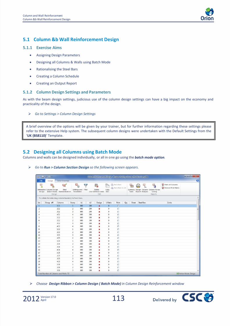
7/22/2019 Standard Training Manual
http://slidepdf.com/reader/full/standard-training-manual 114/286
113
Column and Wall Reinforcement
Column &b Wall Reinforcement Design
2012 Version 17.0April
5.1 Column &b Wall Reinforcement Design
5.1.1 Exercise Aims
Assigning Design Parameters
Designing all Columns & Walls using Batch Mode
Rationalising the Steel Bars
Creating a Column Schedule
Creating an Output Report
5.1.2 Column Design Settings and Parameters
As with the beam design settings, judicious use of the column design settings can have a big impact on the economy and
practicality of the design.
Go to Settings > Column Design Settings
5.2 Designing all Columns using Batch ModeColumns and walls can be designed individually, or all in one go using the batch mode option.
Go to Run > Column Section Design so the following screen appears.
Choose Design Ribbon > Column Design ( Batch Mode) in Column Design Reinforcement window
A brief overview of the options will be given by your trainer, but for further information regarding these settings please
refer to the extensive Help system. The subsequent column designs were undertaken with the Default Settings from the
‘UK (BS8110)’ Template.
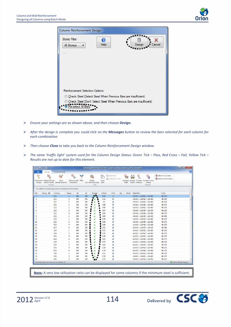
7/22/2019 Standard Training Manual
http://slidepdf.com/reader/full/standard-training-manual 115/286
114
Column and Wall Reinforcement
Designing all Columns using Batch Mode
2012 Version 17.0April
Ensure your settings are as shown above, and then choose Design.
After the design is complete you could click on the Messages button to review the bars selected for each column for
each combination.
Then choose Close to take you back to the Column Reinforcement Design window.
The same ‘traffic light’ system used for the Column Design Status: Green Tick – Pass, Red Cross – Fail, Yellow Tick –
Results are not up to date for this element.
Note: A very low utilisation ratio can be displayed for some columns if the minimum steel is sufficient.
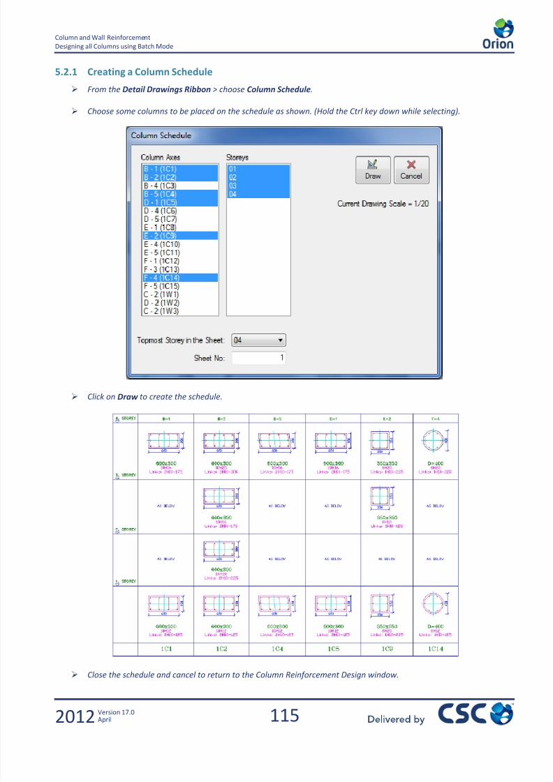
7/22/2019 Standard Training Manual
http://slidepdf.com/reader/full/standard-training-manual 116/286
115
Column and Wall Reinforcement
Designing all Columns using Batch Mode
2012 Version 17.0April
5.2.1 Creating a Column Schedule
From the Detail Drawings Ribbon > choose Column Schedule.
Choose some columns to be placed on the schedule as shown. (Hold the Ctrl key down while selecting).
Click onDraw
to create the schedule.
Close the schedule and cancel to return to the Column Reinforcement Design window.
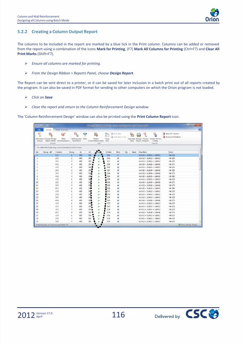
7/22/2019 Standard Training Manual
http://slidepdf.com/reader/full/standard-training-manual 117/286
116
Column and Wall Reinforcement
Designing all Columns using Batch Mode
2012 Version 17.0April
5.2.2 Creating a Column Output Report
The columns to be included in the report are marked by a blue tick in the Print column. Columns can be added or removed
from the report using a combination of the icons Mark for Printing, (F7) Mark All Columns for Printing (Ctrl+F7) and Clear All
Print Marks (Shift+F7).
Ensure all columns are marked for printing.
From the Design Ribbon > Reports Panel, choose Design Report .
The Report can be sent direct to a printer, or it can be saved for later inclusion in a batch print out of all reports created by
the program. It can also be saved in PDF format for sending to other computers on which the Orion program is not loaded.
Click on Save
Close the report and return to the Column Reinforcement Design window.
The ‘Column Reinforcement Design’ window can also be printed using the Print Column Report icon.
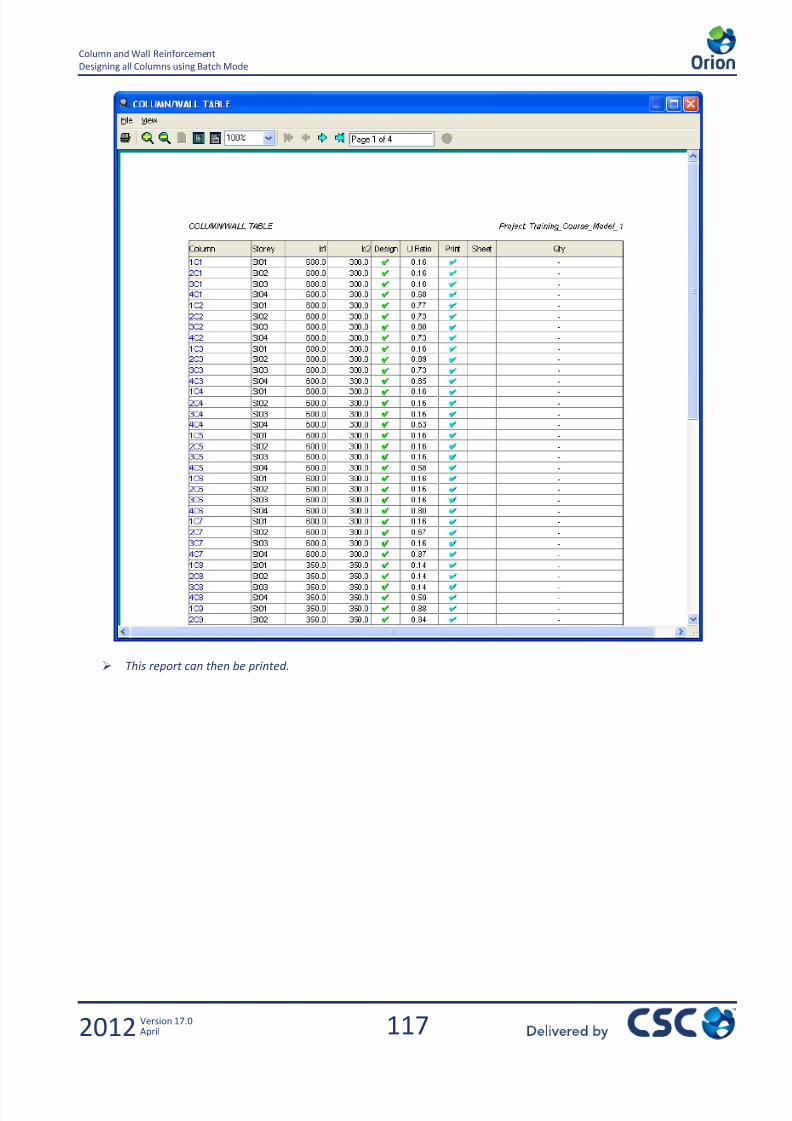
7/22/2019 Standard Training Manual
http://slidepdf.com/reader/full/standard-training-manual 118/286
117
Column and Wall Reinforcement
Designing all Columns using Batch Mode
2012 Version 17.0April
This report can then be printed.
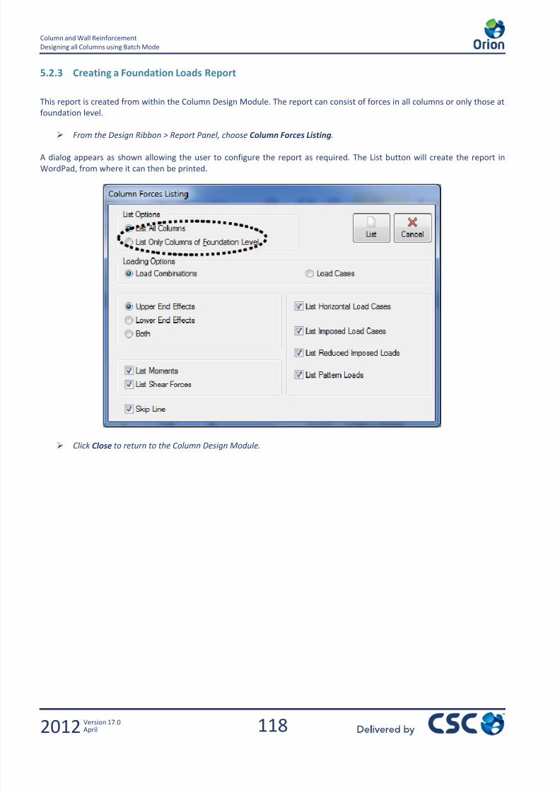
7/22/2019 Standard Training Manual
http://slidepdf.com/reader/full/standard-training-manual 119/286
118
Column and Wall Reinforcement
Designing all Columns using Batch Mode
2012 Version 17.0April
5.2.3 Creating a Foundation Loads Report
This report is created from within the Column Design Module. The report can consist of forces in all columns or only those at
foundation level.
From the Design Ribbon > Report Panel, choose Column Forces Listing.
A dialog appears as shown allowing the user to configure the report as required. The List button will create the report in
WordPad, from where it can then be printed.
Click Close to return to the Column Design Module.
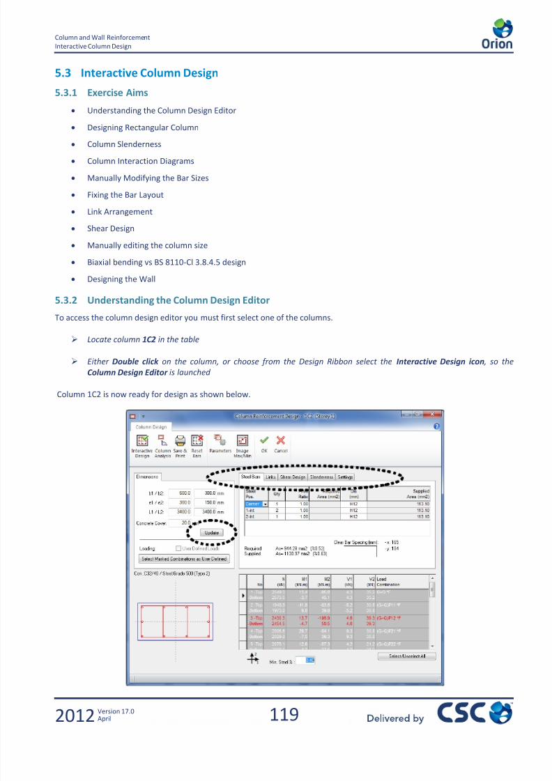
7/22/2019 Standard Training Manual
http://slidepdf.com/reader/full/standard-training-manual 120/286
119
Column and Wall Reinforcement
Interactive Column Design
2012 Version 17.0April
5.3 Interactive Column Design
5.3.1 Exercise Aims
Understanding the Column Design Editor
Designing Rectangular Column
Column Slenderness
Column Interaction Diagrams
Manually Modifying the Bar Sizes
Fixing the Bar Layout
Link Arrangement
Shear Design
Manually editing the column size
Biaxial bending vs BS 8110-Cl 3.8.4.5 design
Designing the Wall
5.3.2 Understanding the Column Design Editor
To access the column design editor you must first select one of the columns.
Locate column 1C2 in the table
Either Double click on the column, or choose from the Design Ribbon select the Interactive Design icon , so the
Column Design Editor is launched
Column 1C2 is now ready for design as shown below.
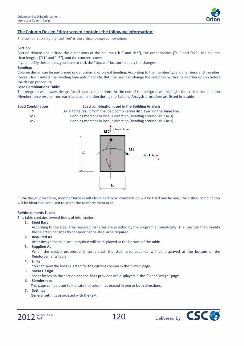
7/22/2019 Standard Training Manual
http://slidepdf.com/reader/full/standard-training-manual 121/286
120
Column and Wall Reinforcement
Interactive Column Design
2012 Version 17.0April
The Column Design Editor screen contains the following information:
The combination highlighted ‘red’ is the critical design combination.
Section:
Section dimensions include the dimensions of the column (“b1” and “b2”), the eccentricities (“e1” and “e2”), the column
clear lengths (“L1” and “L2”), and the concrete cover. If you modify these fields, you have to click the “Update” button to apply the changes.
Bending:
Column design can be performed under uni-axial or biaxial bending. According to the member type, dimensions and member
forces, Orion selects the bending type automatically. But, the user can change the selection by clicking another option before
the design procedure.
Load Combinations Table:
The program will always design for all load combinations. At the end of the design it will highlight the critical combination.
Member force results from each load combination during the Building Analysis procedure are listed in a table.
Load Combination Load combination used in the Building Analysis
N Axial force result from the load combination displayed on the same line.
M1 Bending moment in local 1 direction (bending around Dir 2 axis)
M2 Bending moment in local 2 direction (bending around Dir 1 axis)
In the design procedure, member force results from each load combination will be tried one by one. The critical combination
will be identified and used to select the reinforcement area.
Reinforcements Table:
This table contains several items of information:
1. Steel Bars
According to the steel area required, bar sizes are selected by the program automatically. The user can then modify
the selected bar sizes by considering the steel area required.
2. Required AsAfter design the steel area required will be displayed at the bottom of the table.
3. Supplied As
When the design procedure is completed, the steel area supplied will be displayed at the bottom of the
Reinforcements table.
4. Links
You can view the links selected for the current column in the “Links” page.
5. Shear Design
Shear forces on the section and the links provided are displayed in the “Shear Design” page.
6. Slenderness
This page can be used to indicate the column as braced in one or both directions.
7. Settings
General settings associated with the text.
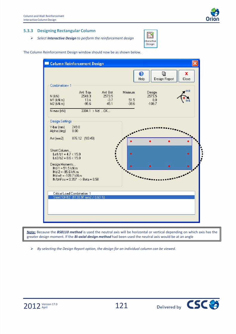
7/22/2019 Standard Training Manual
http://slidepdf.com/reader/full/standard-training-manual 122/286
121
Column and Wall Reinforcement
Interactive Column Design
2012 Version 17.0April
5.3.3 Designing Rectangular Column
Select Interactive Design to perform the reinforcement design
The Column Reinforcement Design window should now be as shown below.
By selecting the Design Report option, the design for an individual column can be viewed.
Note: Because the BS8110 method is used the neutral axis will be horizontal or vertical depending on which axis has the
greater design moment. If the Bi-axial design method had been used the neutral axis would be at an angle

7/22/2019 Standard Training Manual
http://slidepdf.com/reader/full/standard-training-manual 123/286
122
Column and Wall Reinforcement
Interactive Column Design
2012 Version 17.0April
Choose Close to exit back to the Column Design Editor.
The column has been designed using 10H12 bars and Combination 3 is the most critical.

7/22/2019 Standard Training Manual
http://slidepdf.com/reader/full/standard-training-manual 124/286
123
Column and Wall Reinforcement
Interactive Column Design
2012 Version 17.0April
5.3.4 Column Slenderness
A column may be considered braced in a given plane if lateral stability to the structure as a whole is provided by walls or
bracing designed to resist all lateral forces in that plane. If you check the User Defined Bracing for Columns and Walls option
in the Project Parameters form, then you can specify the bracing condition for the X and Y directions manually. Otherwise
Orion checks the bracing for each direction automatically based on the drift of the storey levels. In both situations, you can
change the bracing condition for a column on the Slenderness tab. The beta value is determined separately for braced andunbraced columns and additional moments will be calculated accordingly.
Click on the Slenderness tab in the Reinforcements table.
The column is currently set as braced and because it is being classified as short, no additional moments are being added to
the initial moments.
Try un-bracing the column in the both X and Y directions and redesigning. You should find that this results in the
column being classified as slender and consequently additional moments are added. The column has now beendesigned using 10H20 bars.

7/22/2019 Standard Training Manual
http://slidepdf.com/reader/full/standard-training-manual 125/286
124
Column and Wall Reinforcement
Interactive Column Design
2012 Version 17.0April
5.3.5 Column Interaction Diagrams
After the determination of the column reinforcement, Column Interaction Diagrams can be prepared. Using the interaction
diagrams, a better understanding of the behaviour of the column can be achieved. Column interaction diagrams can be
drawn using the "Column Analysis" button.
Click on the Column Analysis button in the Column Design Ribbon at the top of the Editor.
The red line is the Dir 1 column capacity and the blue line Dir 2. Also plotted are the top and bottom moments determined
during the analysis of the building for each of the combinations. The horizontal red line indicates the axial load limit
determined by the code.
It can be seen that the design moments are very close to the moment capacity in dir 2.
The blue line on this diagram shows the M1-M2 capacities at the given axial load level.
Click on Close to return to the Editor.
Reduce the size of the bars to H10 as shown below. Note that the provided (sufficient) area is now less than the area
required.
Column
Axial
Capacity
Column
Critical Axial
Load
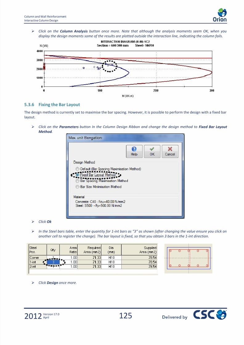
7/22/2019 Standard Training Manual
http://slidepdf.com/reader/full/standard-training-manual 126/286
125
Column and Wall Reinforcement
Interactive Column Design
2012 Version 17.0April
Click on the Column Analysis button once more. Note that although the analysis moments seem OK, when you
display the design moments some of the results are plotted outside the interaction line, indicating the column fails.
5.3.6 Fixing the Bar Layout
The design method is currently set to maximise the bar spacing. However, it is possible to perform the design with a fixed bar
layout.
Click on the Parameters button In the Column Design Ribbon and change the design method to Fixed Bar Layout
Method .
Click Ok
In the Steel bars table, enter the quantity for 1- int bars as “3” as shown (after changing the value ensure you click on
another cell to register the change). The bar layout is fixed, so that you obtain 3 bars in the 1-int direction.
Click Design once more.

7/22/2019 Standard Training Manual
http://slidepdf.com/reader/full/standard-training-manual 127/286
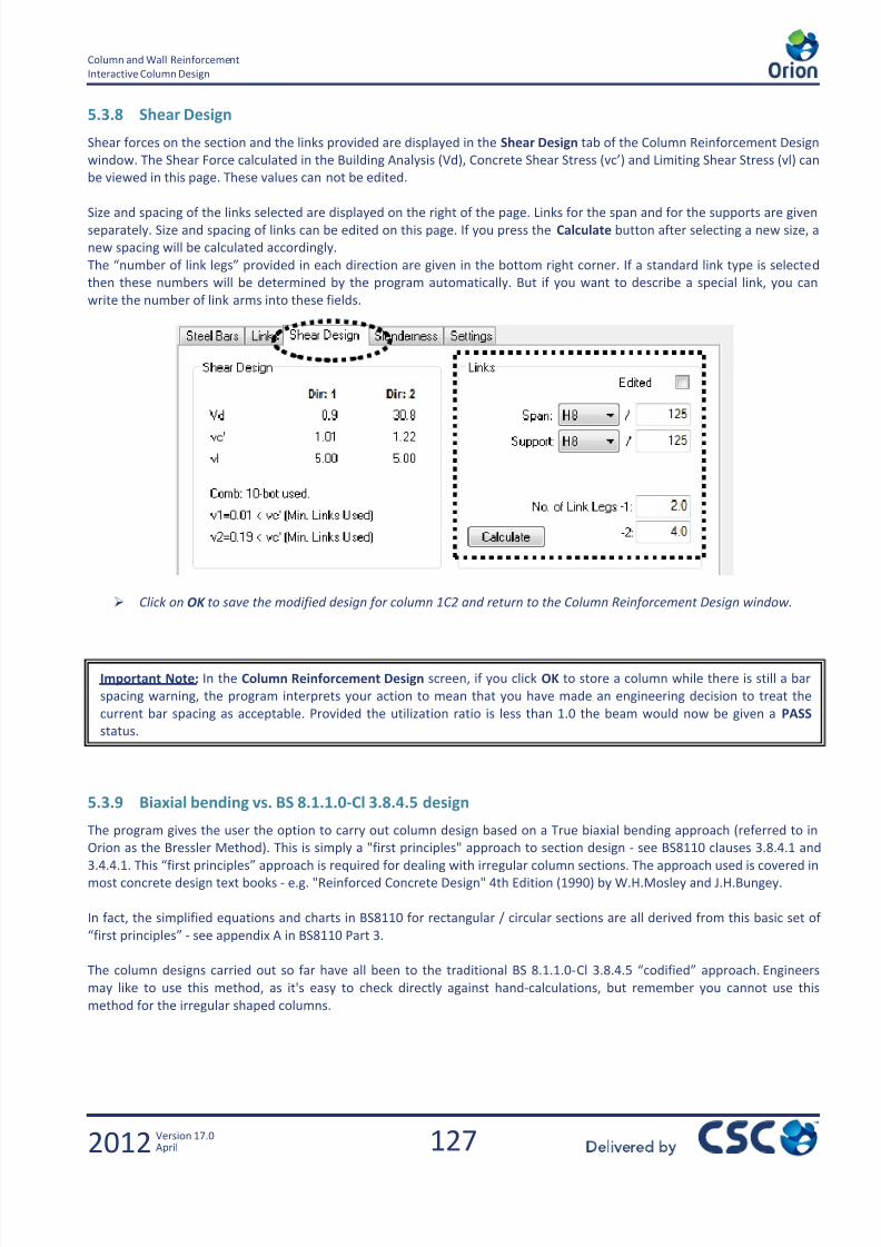
7/22/2019 Standard Training Manual
http://slidepdf.com/reader/full/standard-training-manual 128/286
127
Column and Wall Reinforcement
Interactive Column Design
2012 Version 17.0April
5.3.8 Shear Design
Shear forces on the section and the links provided are displayed in the Shear Design tab of the Column Reinforcement Design
window. The Shear Force calculated in the Building Analysis (Vd), Concrete Shear Stress (vc’) and Limiting Shear Stress (vl) can
be viewed in this page. These values can not be edited.
Size and spacing of the links selected are displayed on the right of the page. Links for the span and for the supports are givenseparately. Size and spacing of links can be edited on this page. If you press the Calculate button after selecting a new size, a
new spacing will be calculated accordingly.
The “number of link legs” provided in each direction are given in the bottom right corner. If a standard link type is selecte d
then these numbers will be determined by the program automatically. But if you want to describe a special link, you can
write the number of link arms into these fields.
Click on OK to save the modified design for column 1C2 and return to the Column Reinforcement Design window.
5.3.9 Biaxial bending vs. BS 8.1.1.0-Cl 3.8.4.5 design
The program gives the user the option to carry out column design based on a True biaxial bending approach (referred to in
Orion as the Bressler Method). This is simply a "first principles" approach to section design - see BS8110 clauses 3.8.4.1 and3.4.4.1. This “first principles” approach is required for dealing with irregular column sections. The approach used is covered in
most concrete design text books - e.g. "Reinforced Concrete Design" 4th Edition (1990) by W.H.Mosley and J.H.Bungey.
In fact, the simplified equations and charts in BS8110 for rectangular / circular sections are all derived from this basic set of
“first principles” - see appendix A in BS8110 Part 3.
The column designs carried out so far have all been to the traditional BS 8.1.1.0- Cl 3.8.4.5 “codified” approach. Engineers
may like to use this method, as it's easy to check directly against hand-calculations, but remember you cannot use this
method for the irregular shaped columns.
Important Note: In the Column Reinforcement Design screen, if you click OK to store a column while there is still a bar
spacing warning, the program interprets your action to mean that you have made an engineering decision to treat the
current bar spacing as acceptable. Provided the utilization ratio is less than 1.0 the beam would now be given a PASS
status.

7/22/2019 Standard Training Manual
http://slidepdf.com/reader/full/standard-training-manual 129/286
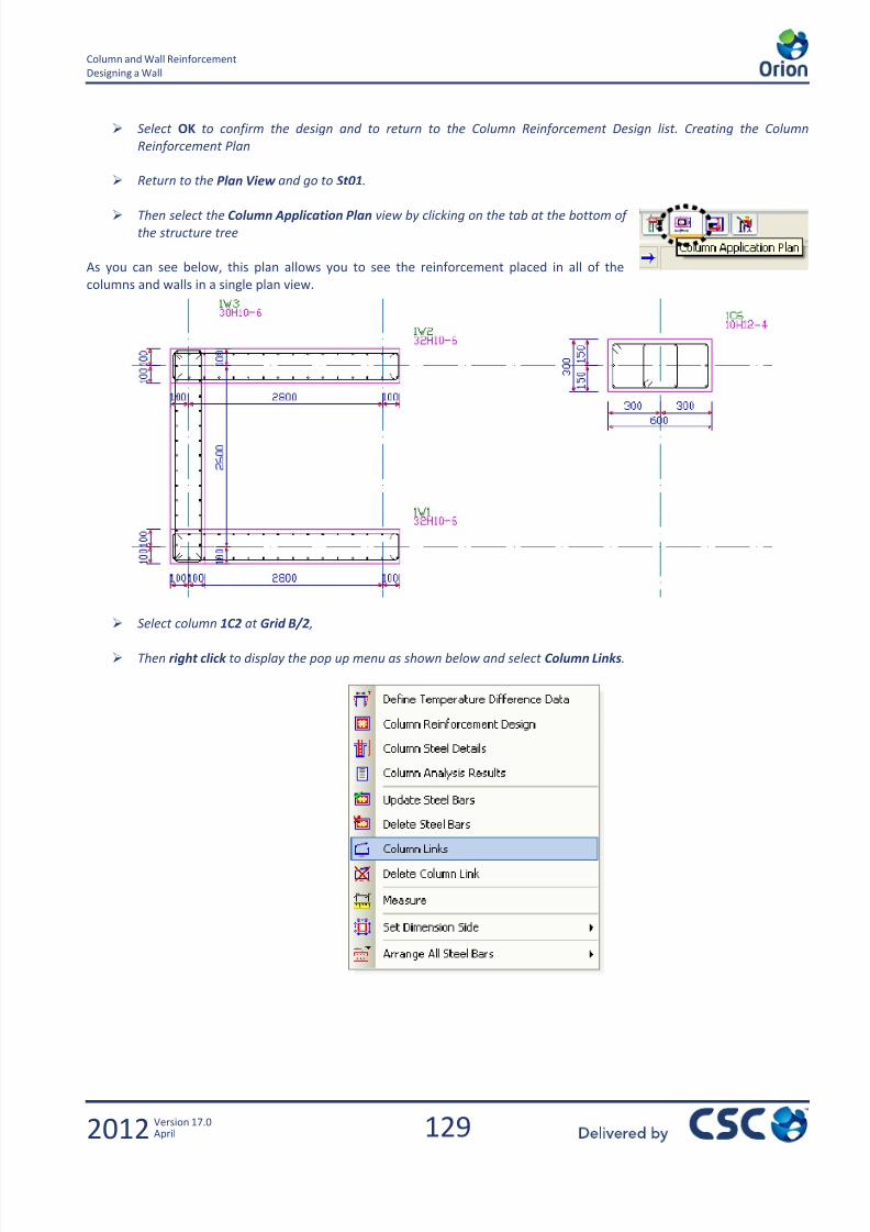
7/22/2019 Standard Training Manual
http://slidepdf.com/reader/full/standard-training-manual 130/286
129
Column and Wall Reinforcement
Designing a Wall
2012 Version 17.0April
Select OK to confirm the design and to return to the Column Reinforcement Design list. Creating the Column
Reinforcement Plan
Return to the Plan View and go to St01.
Then select the Column Application Plan view by clicking on the tab at the bottom of
the structure tree
As you can see below, this plan allows you to see the reinforcement placed in all of the
columns and walls in a single plan view.
Select column 1C2 at Grid B/2 ,
Then right click to display the pop up menu as shown below and select Column Links.
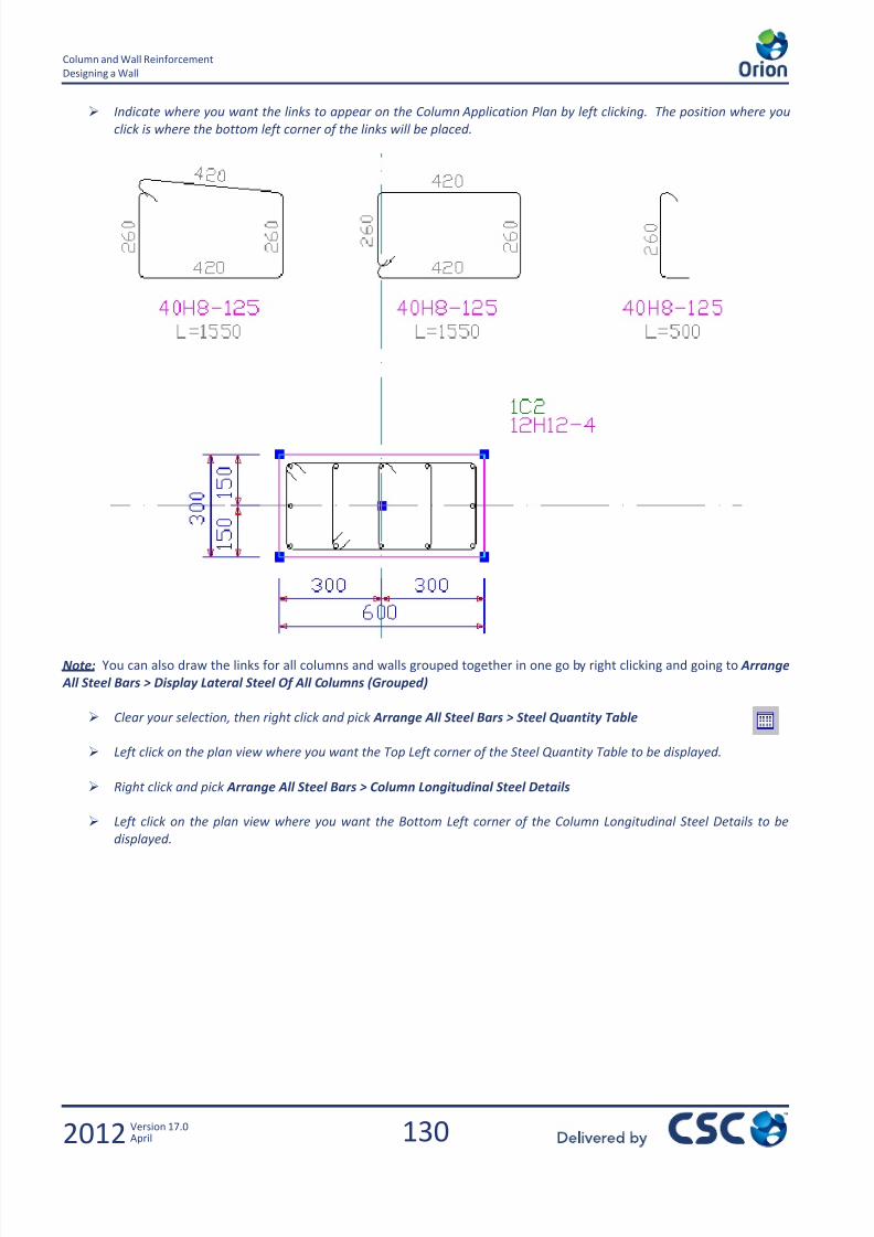
7/22/2019 Standard Training Manual
http://slidepdf.com/reader/full/standard-training-manual 131/286
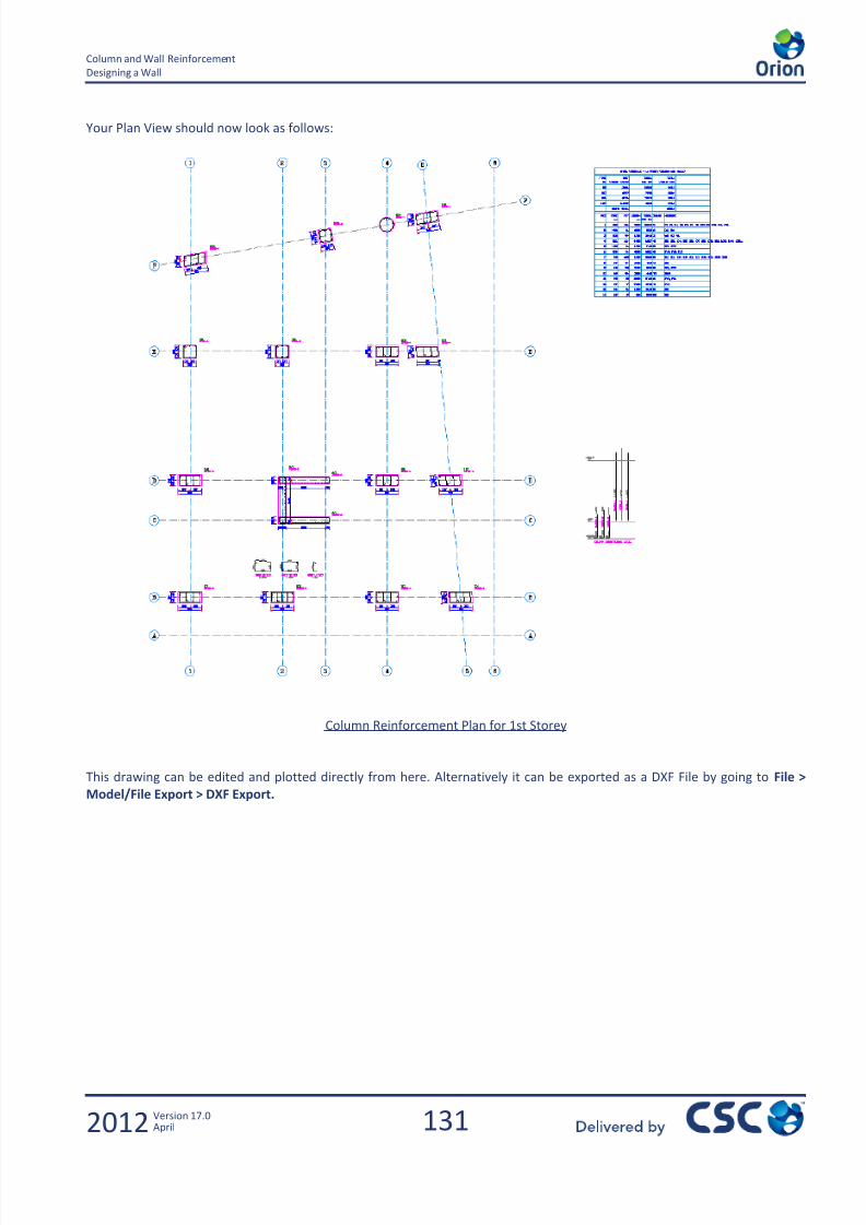
7/22/2019 Standard Training Manual
http://slidepdf.com/reader/full/standard-training-manual 132/286
131
Column and Wall Reinforcement
Designing a Wall
2012 Version 17.0April
Your Plan View should now look as follows:
Column Reinforcement Plan for 1st Storey
This drawing can be edited and plotted directly from here. Alternatively it can be exported as a DXF File by going to File >
Model/File Export > DXF Export.

7/22/2019 Standard Training Manual
http://slidepdf.com/reader/full/standard-training-manual 133/286

7/22/2019 Standard Training Manual
http://slidepdf.com/reader/full/standard-training-manual 134/286
133
Slab Design
2012 Version 17.0April
6.0 Slab Design
Slab Design and Detailing

7/22/2019 Standard Training Manual
http://slidepdf.com/reader/full/standard-training-manual 135/286

7/22/2019 Standard Training Manual
http://slidepdf.com/reader/full/standard-training-manual 136/286
135
Slab Design
Slab Design and Detailing
2012 Version 17.0April
6.1 Slab Design and Detailing
6.1.1 Exercise Aims
Slab Design Settings
Creating Slab Reinforcement Strips Horizontal & Vertical
Creating a Slab Reinforcement Output Report
6.1.2 Slab Design Settings
As with the Beams and Columns, all settings associated with the design of slabs can be located in Settings > Slab DesignSettings.
The Design tab allows you to control the Cover, Top Steel Extension Lengths, Slab Span Lengths and the Support Band Beam
Widths.
Go to the Steel Bars tab and make sure the Steel Bar Spacing Step is set to 25mm to ensure that all bars within the
slab will be at multiples of 25mm In addition, as shown below, the bars will be spaced at no less than 100mm and no
greater than 250mm.
Additional slab steel detailing preferences are controlled via the View tab
Note: This process uses the slab coefficient method from the tables in BS8110. This is independent of the general building
analysis and can therefore be carried out before or after the general building analysis. This method takes NO account of
openings or concentrated point/line/patch loads on the slabs.
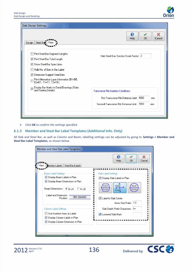
7/22/2019 Standard Training Manual
http://slidepdf.com/reader/full/standard-training-manual 137/286
136
Slab Design
Slab Design and Detailing
2012 Version 17.0April
Click OK to confirm the settings specified
6.1.3 Member and Steel Bar Label Templates (Additional Info. Only)
All Slab and Steel Bar, as well as Column and Beam, labelling settings can be adjusted by going to Settings > Member and
Steel Bar Label Templates, as shown below
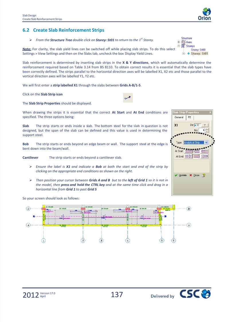
7/22/2019 Standard Training Manual
http://slidepdf.com/reader/full/standard-training-manual 138/286

7/22/2019 Standard Training Manual
http://slidepdf.com/reader/full/standard-training-manual 139/286
138
Slab Design
Create Slab Reinforcement Strips
2012 Version 17.0April
Create another similar strip labelled X2 by repeating the process between Grids B-C/1-6.
Now a vertical strip will be inserted.
Change the Dir setting to Y to show that you are cutting a vertical strip in the
plan view.
Set the No: setting to 1 so that the strip label is Y1
Keep the At Start setting as Bob
As this strip is going to cut through the cantilever at the end, change the At
End setting to Cantilever
If you drew the strip Y1 and you received a warning message as shown below, this is
because the strip has failed to satisfy the L/d deflection check. L is calculated at exactly
the point where you cut the strip.
After creating the 3 strips your screen should look as follows:
Note: When placing strips you may encounter warning messages similar to the one above. Although the steel provided is
sufficient for strength it is failing the span/effective depth check deflection check. This problem will be resolved later by
editing the bar layout or changing the slab depth.
Note: Although only two strips have been created in the model in the X direction, strips for all slab panels / conditions
should be created to complete the floor design in both the X and the Y direction.
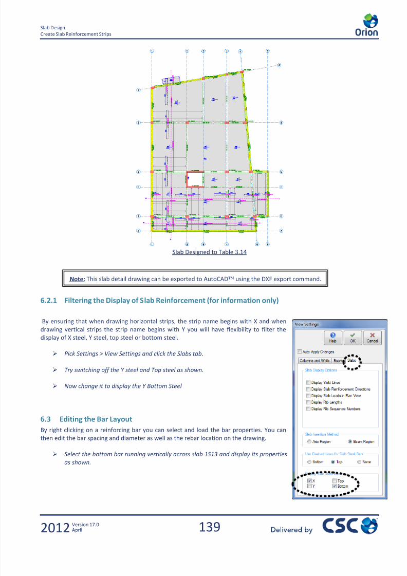
7/22/2019 Standard Training Manual
http://slidepdf.com/reader/full/standard-training-manual 140/286
139
Slab Design
Create Slab Reinforcement Strips
2012 Version 17.0April
Slab Designed to Table 3.14
6.2.1 Filtering the Display of Slab Reinforcement (for information only)
By ensuring that when drawing horizontal strips, the strip name begins with X and when
drawing vertical strips the strip name begins with Y you will have flexibility to filter the
display of X steel, Y steel, top steel or bottom steel.
Pick Settings > View Settings and click the Slabs tab.
Try switching off the Y steel and Top steel as shown.
Now change it to display the Y Bottom Steel
6.3 Editing the Bar Layout
By right clicking on a reinforcing bar you can select and load the bar properties. You can
then edit the bar spacing and diameter as well as the rebar location on the drawing.
Select the bottom bar running vertically across slab 1S13 and display its properties
as shown.
Note: This slab detail drawing can be exported to AutoCAD using the DXF export command.
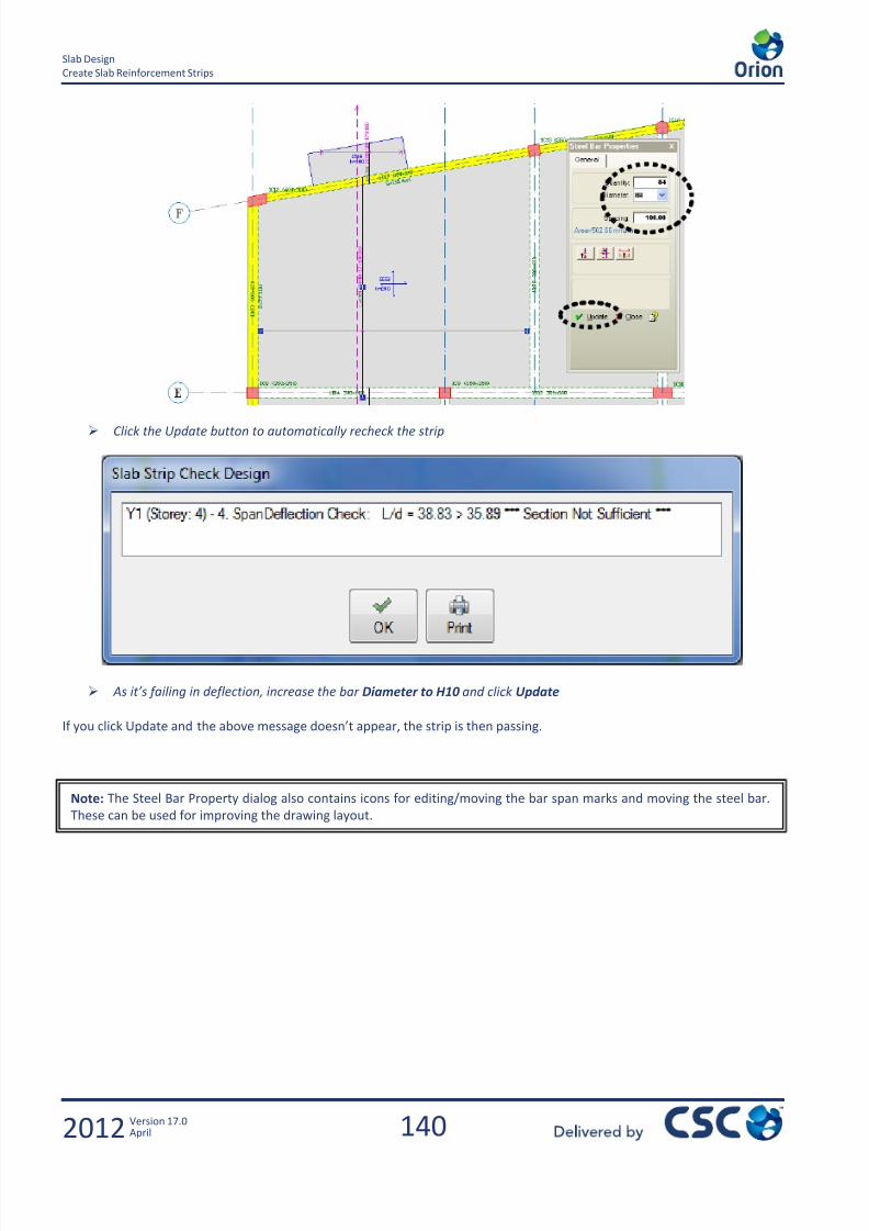
7/22/2019 Standard Training Manual
http://slidepdf.com/reader/full/standard-training-manual 141/286
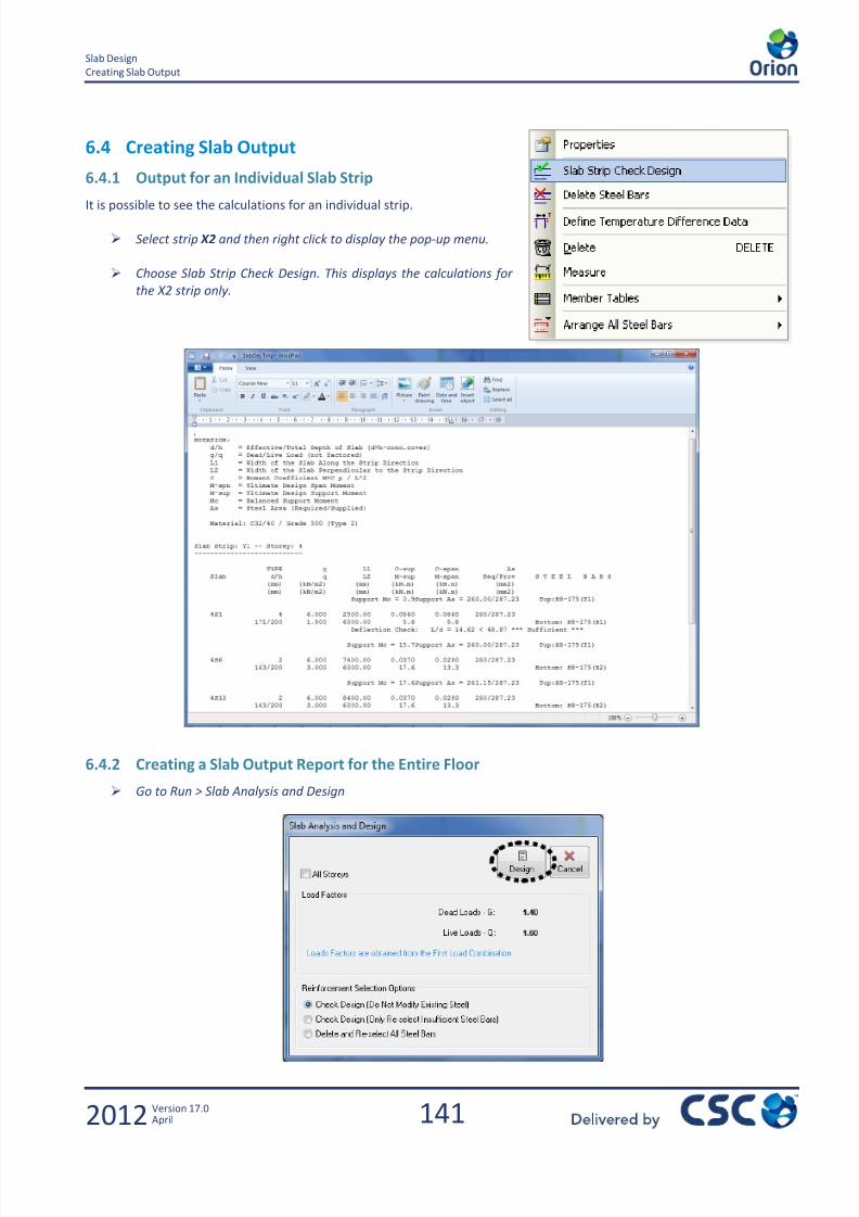
7/22/2019 Standard Training Manual
http://slidepdf.com/reader/full/standard-training-manual 142/286
141
Slab Design
Creating Slab Output
2012 Version 17.0April
6.4 Creating Slab Output
6.4.1 Output for an Individual Slab Strip
It is possible to see the calculations for an individual strip.
Select strip X2 and then right click to display the pop-up menu.
Choose Slab Strip Check Design. This displays the calculations for
the X2 strip only.
6.4.2 Creating a Slab Output Report for the Entire Floor
Go to Run > Slab Analysis and Design

7/22/2019 Standard Training Manual
http://slidepdf.com/reader/full/standard-training-manual 143/286

7/22/2019 Standard Training Manual
http://slidepdf.com/reader/full/standard-training-manual 144/286

7/22/2019 Standard Training Manual
http://slidepdf.com/reader/full/standard-training-manual 145/286
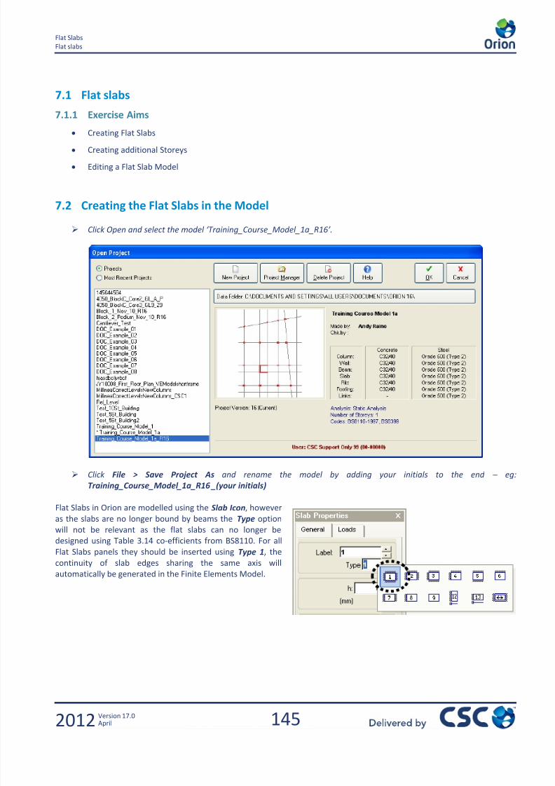
7/22/2019 Standard Training Manual
http://slidepdf.com/reader/full/standard-training-manual 146/286
145
Flat Slabs
Flat slabs
2012 Version 17.0April
7.1 Flat slabs
7.1.1 Exercise Aims
Creating Flat Slabs
Creating additional Storeys
Editing a Flat Slab Model
7.2 Creating the Flat Slabs in the Model
Click Open and select the model ‘Training_Course_Model_1a_R16’.
Click File > Save Project As and rename the model by adding your initials to the end – eg:
Training_Course_Model_1a_R16 _(your initials)
Flat Slabs in Orion are modelled using the Slab Icon, however
as the slabs are no longer bound by beams the Type option
will not be relevant as the flat slabs can no longer be
designed using Table 3.14 co-efficients from BS8110. For all
Flat Slabs panels they should be inserted using Type 1, the
continuity of slab edges sharing the same axis will
automatically be generated in the Finite Elements Model.
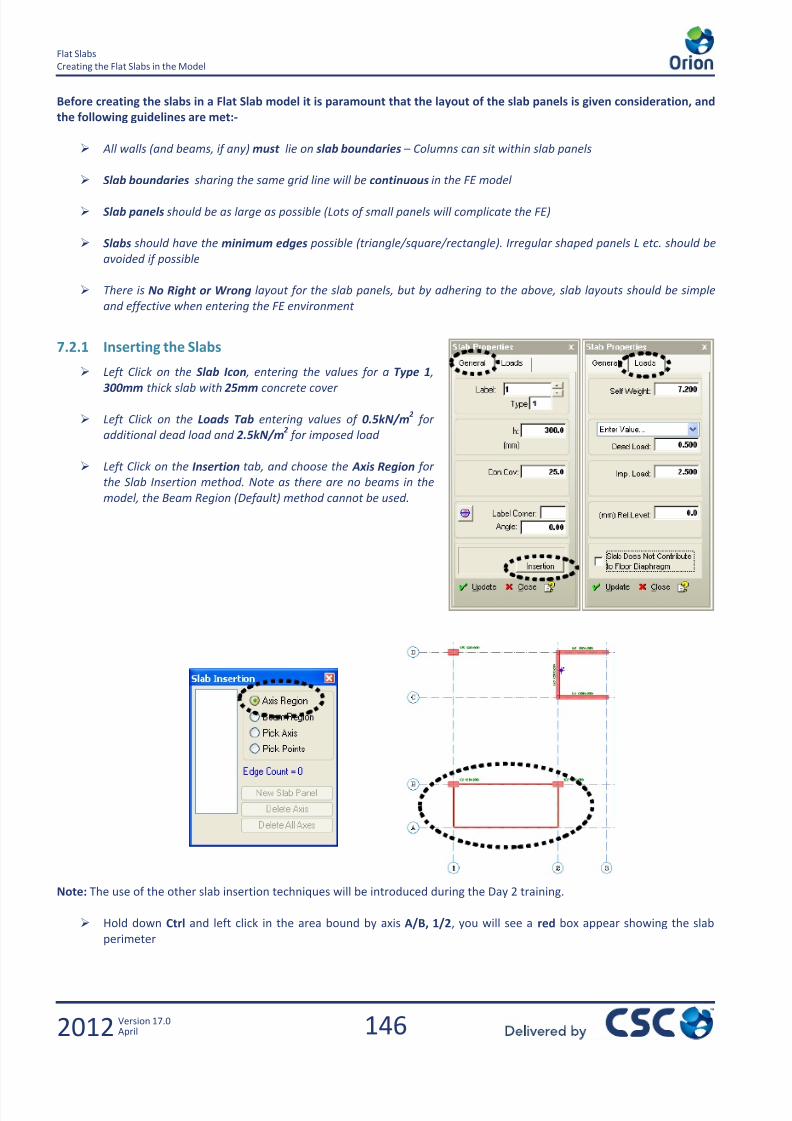
7/22/2019 Standard Training Manual
http://slidepdf.com/reader/full/standard-training-manual 147/286
146
Flat Slabs
Creating the Flat Slabs in the Model
2012 Version 17.0April
Before creating the slabs in a Flat Slab model it is paramount that the layout of the slab panels is given consideration, and
the following guidelines are met:-
All walls (and beams, if any) must lie on slab boundaries – Columns can sit within slab panels
Slab boundaries sharing the same grid line will be continuous in the FE model
Slab panels should be as large as possible (Lots of small panels will complicate the FE)
Slabs should have the minimum edges possible (triangle/square/rectangle). Irregular shaped panels L etc. should be
avoided if possible
There is No Right or Wrong layout for the slab panels, but by adhering to the above, slab layouts should be simple
and effective when entering the FE environment
7.2.1 Inserting the Slabs
Left Click on the Slab Icon , entering the values for a Type 1 ,
300mm thick slab with 25mm concrete cover
Left Click on the Loads Tab entering values of 0.5kN/m2 for
additional dead load and 2.5kN/m2 for imposed load
Left Click on the Insertion tab, and choose the Axis Region for
the Slab Insertion method. Note as there are no beams in the
model, the Beam Region (Default) method cannot be used.
Note: The use of the other slab insertion techniques will be introduced during the Day 2 training.
Hold down Ctrl and left click in the area bound by axis A/B, 1/2, you will see a red box appear showing the slab
perimeter
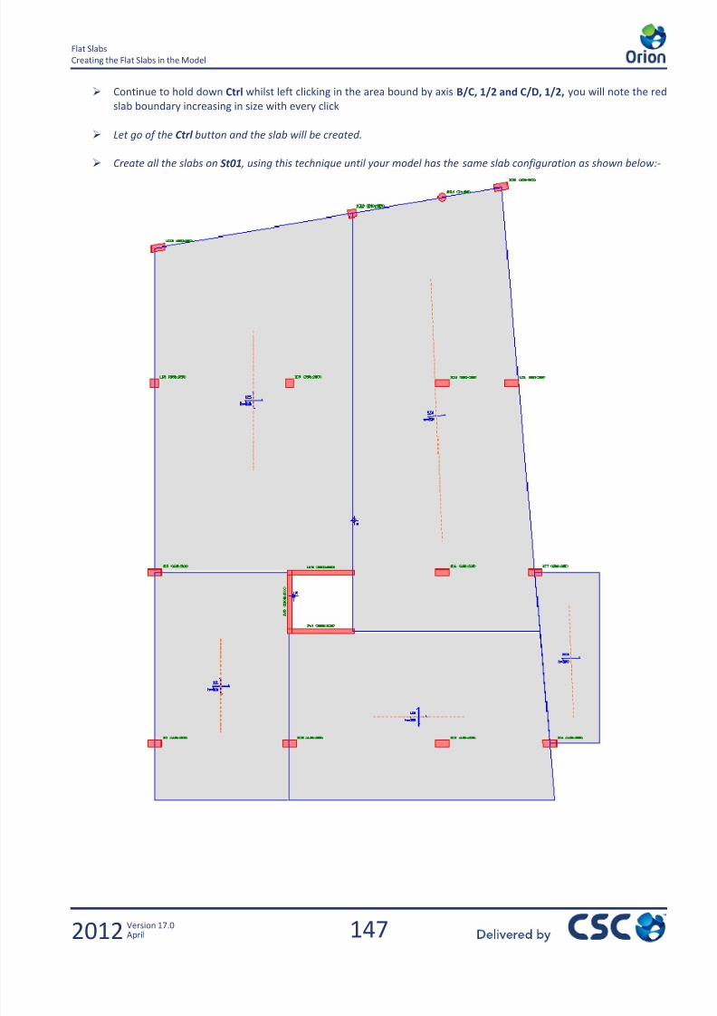
7/22/2019 Standard Training Manual
http://slidepdf.com/reader/full/standard-training-manual 148/286
147
Flat Slabs
Creating the Flat Slabs in the Model
2012 Version 17.0April
Continue to hold down Ctrl whilst left clicking in the area bound by axis B/C, 1/2 and C/D, 1/2, you will note the red
slab boundary increasing in size with every click
Let go of the Ctrl button and the slab will be created.
Create all the slabs on St01 , using this technique until your model has the same slab configuration as shown below:-

7/22/2019 Standard Training Manual
http://slidepdf.com/reader/full/standard-training-manual 149/286
148
Flat Slabs
Creating Slab Loads and Openings
2012 Version 17.0April
7.3 Creating Slab Loads and Openings
7.3.1 Slab Loads
It is possible now the slabs have been inserted into the model to create Point, Line and Patch loads directly onto the
slab. To demonstrate this we are going to place a Line Load on the perimeter of the slab.
To aid in the selection of the correct location of the line loads, it may help to switch the Axis Layer off, using
the Axis Layer Toolbar
Left Click on the Slab Load Tool, and specify a Line Load of magnitude 10kN/m for the Dead Loads only.
Left Click and drag to define the line loads around the perimeter, taking care to snap onto the slab corners.
Note: Point and Patch loads can also be applied to the slab using the same
techniques. If a dxf had been imported into this model it would be possible to
snap onto the shadow, to enable to accurately model the location of any
additional loads on the slab, such as a corridor or plant room.

7/22/2019 Standard Training Manual
http://slidepdf.com/reader/full/standard-training-manual 150/286
149
Flat Slabs
Creating Slab Loads and Openings
2012 Version 17.0April
As the line load has been created over more than one slab, a warning will appear asking you to confirm this was your
intention.
As we will be doing an FE Floor Analysis, click OK
Place the remainder of the loads around the perimeter, as shown below:-
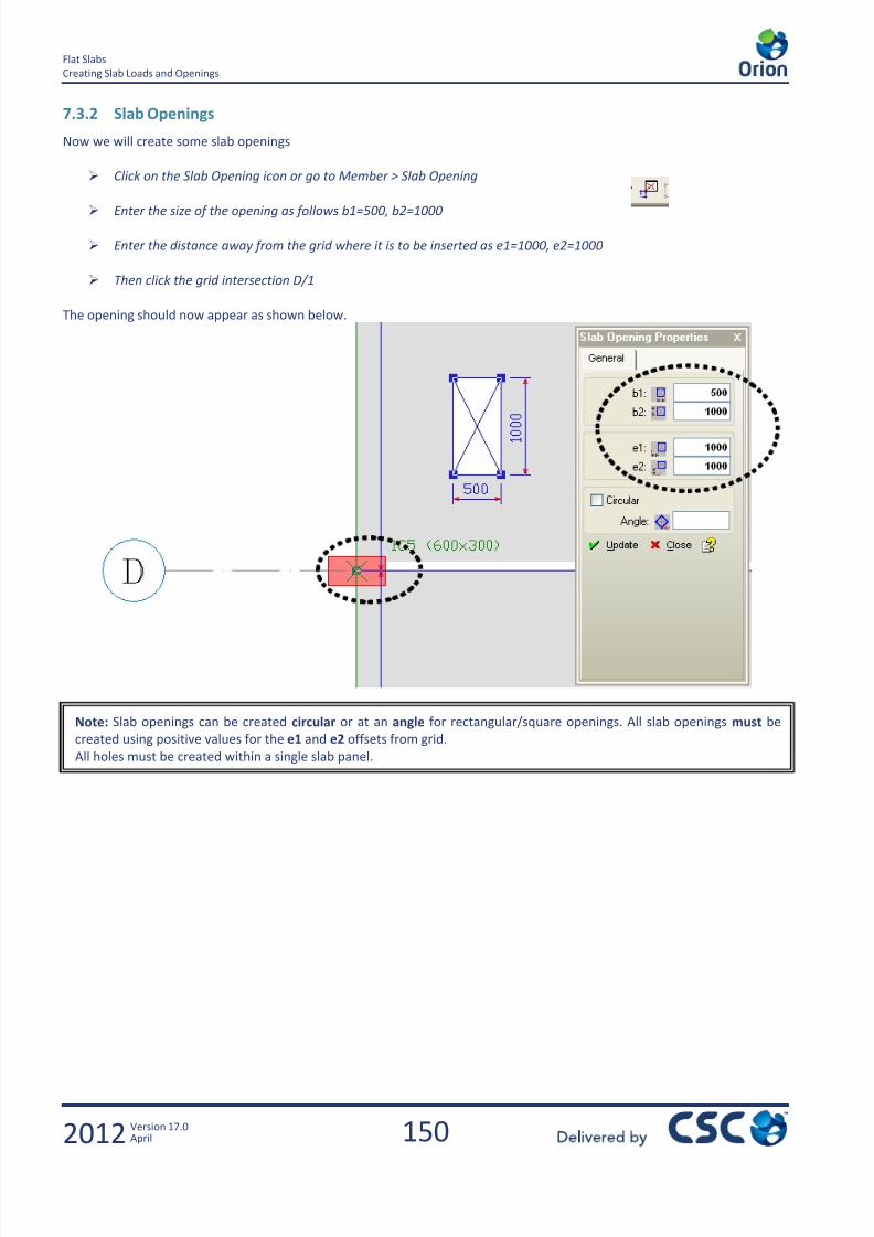
7/22/2019 Standard Training Manual
http://slidepdf.com/reader/full/standard-training-manual 151/286

7/22/2019 Standard Training Manual
http://slidepdf.com/reader/full/standard-training-manual 152/286
151
Flat Slabs
Creating Additional Storeys
2012 Version 17.0April
7.4 Creating Additional Storeys
7.4.1 Storey Information
As we did in this mornings exercise for a Beam and Column Structure, create a 4 storey model which has the followingparameters:-
St04 Copy of St01 excluding Slab Loads and Slab Openings
Create a Type 1 – 300mm thick slab to the top of the shear core
St03 Copy the Storey Information from St01 to St03
St02 A duplicate of Storey 3 (St03)
St01 Original Storey – No editing necessary
Storey Height for all floors is to be 4000mm
Duplicate Storeys – The use of duplicate storeys should be used wherever genuine duplicate floors exist within the model.
The benefits as explained in the Beam and Column example still exist, but also when performing the Finite Elements Load
Chase down, duplicate storeys will not need to be re-analysed, therefore speeding up the load chase down procedure.
Unique Storeys – There will always be a minimum of 3 Unique Storeys in any multi-storey structure (shown by the Blue Dot
by the side of the Storey Label in the Workspace area).
St01 – The first floor generated in the model
Top Storey
Penultimate Top Storey
Note: The top and the penultimate top storey cannot be identical, as the columns / walls at the top floor, only project
below the floor plate. Where as, the lower storeys all have columns / walls which project above & below the floor plate
which will effect the moment distribution from the slabs to the supporting elements.

7/22/2019 Standard Training Manual
http://slidepdf.com/reader/full/standard-training-manual 153/286

7/22/2019 Standard Training Manual
http://slidepdf.com/reader/full/standard-training-manual 154/286
153
Building Analysis for Flat Slab
Creating Additional Storeys
2012 Version 17.0April
8.0 Building Analysis for Flat Slab

7/22/2019 Standard Training Manual
http://slidepdf.com/reader/full/standard-training-manual 155/286

7/22/2019 Standard Training Manual
http://slidepdf.com/reader/full/standard-training-manual 156/286
155
Building Analysis for Flat Slab
Building Analysis for Flat Slabs
2012 Version 17.0April
8.1 Building Analysis for Flat Slabs
8.1.1 Exercise Aims
Model Validity Checking
Run Building Analysis - Pre-Processor
Run Building Analysis - Post-Processor
Viewing the Analysis Output Report
8.1.2 Model Options Settings
From the Run menu choose Building Analysis. This should then display the Analysis Form.
We are going to use the same settings as used for the Beam and Column example, so there is no need to make any
changes to the Parameters / Load Combinations / Material Grades , Click Model Options Model Options
Click on the Settings tab
There is a change in the settings that needs to be made
before we run the Building Analysis for a Flat Slab model
The change is for the ‘Storey Weight and Centre of Gravity’
calculations.
With the beam and column example all the slabs were
supported by beams, therefore the load could be
decomposed from the slabs to the beams. The use of
‘Decomposed Beam Loads’ could be relied upon to generatethe Storey Weight and Notional Horizontal Forces for the
structure.
However, in a Flat Slab Model no beams (or very few) exist,
therefore the ‘Undecomposed Slab Loads’ have to be used
to correctly calculate the Storey Weight and Notional
Horizontal Forces.
If the incorrect setting is made, the user could significantly
underestimate the Storey Weights and the effect of Lateral
Loads on the structure.
Slabs are not modelled in the Building Analysis, which goes some way to explaining why the Undecomposed Loads must be
used for Flat Slab Models. Slabs are replaced by a series of Diaphragms (based on the user’s settings) within the Building
Analysis, but are able to transfer gravity loads to the columns and walls.

7/22/2019 Standard Training Manual
http://slidepdf.com/reader/full/standard-training-manual 157/286
156
Building Analysis for Flat Slab
Building Analysis for Flat Slabs
2012 Version 17.0April
8.1.3 Pre-Analysis – Building Model Check
Click on Building Model Check.
This will check that the building is valid for those conditions indicated.
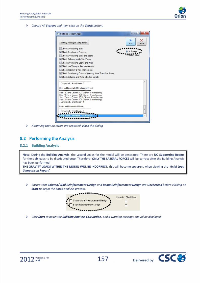
7/22/2019 Standard Training Manual
http://slidepdf.com/reader/full/standard-training-manual 158/286
157
Building Analysis for Flat Slab
Performing the Analysis
2012 Version 17.0April
Choose All Storeys and then click on the Check button.
`
Assuming that no errors are reported, close the dialog
8.2 Performing the Analysis
8.2.1 Building Analysis
Ensure that Column/Wall Reinforcement Design and Beam Reinforcement Design are Unchecked before clicking on
Start to begin the batch analysis process.
Click Start to begin the Building Analysis Calculation , and a warning message should be displayed.
Note: During the Building Analysis, the Lateral Loads for the model will be generated. There are NO Supporting Beams
for the slab loads to be distributed onto. Therefore, ONLY THE LATERAL FORCES will be correct after the Building Analysis
has been performed.
THE GRAVITY LOADS WITHIN THE MODEL WILL BE INCORRECT, this will become apparent when viewing the ‘Axial Load
Comparison Report’.
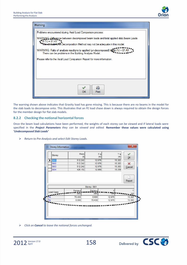
7/22/2019 Standard Training Manual
http://slidepdf.com/reader/full/standard-training-manual 159/286
158
Building Analysis for Flat Slab
Performing the Analysis
2012 Version 17.0April
The warning shown above indicates that Gravity load has gone missing. This is because there are no beams in the model for
the slab loads to decompose onto. This illustrates that an FE load chase down is always required to obtain the design forces
for the member design for flat slab models.
8.2.2 Checking the notional horizontal forces
Once the beam load calculations have been performed, the weights of each storey can be viewed and if lateral loads were
specified in the Project Parameters they can be viewed and edited. Remember these values were calculated using
‘Undecomposed Slab Loads’
Return to Pre-Analysis and select Edit Storey Loads.
Click on Cancel to leave the notional forces unchanged.
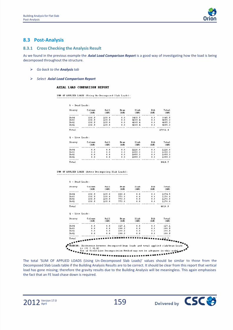
7/22/2019 Standard Training Manual
http://slidepdf.com/reader/full/standard-training-manual 160/286
159
Building Analysis for Flat Slab
Post-Analysis
2012 Version 17.0April
8.3 Post-Analysis
8.3.1 Cross Checking the Analysis Result
As we found in the previous example the Axial Load Comparison Report is a good way of investigating how the load is beingdecomposed throughout the structure.
Go back to the Analysis tab
Select Axial Load Comparison Report
The total ‘SUM OF APPLIED LOADS (Using Un-Decomposed Slab Loads)’ values should be similar to those from the
Decomposed Slab Loads table if the Building Analysis Results are to be correct. It should be clear from this report that vertical
load has gone missing; therefore the gravity results due to the Building Analysis will be meaningless. This again emphasises
the fact that an FE load chase down is required.

7/22/2019 Standard Training Manual
http://slidepdf.com/reader/full/standard-training-manual 161/286
160
Building Analysis for Flat Slab
Post-Analysis
2012 Version 17.0April
8.3.2 Model and Analysis Results Display
The Analysis results can be viewed graphically again, but the only results of any significance will be those for Lateral Loads –
NHF’s / Wind etc.
Click Model and Analysis Results Display
The diaphragms formed during the analysis can be viewed along with the Major Axis Moments and displacements for Nx or
Ny.
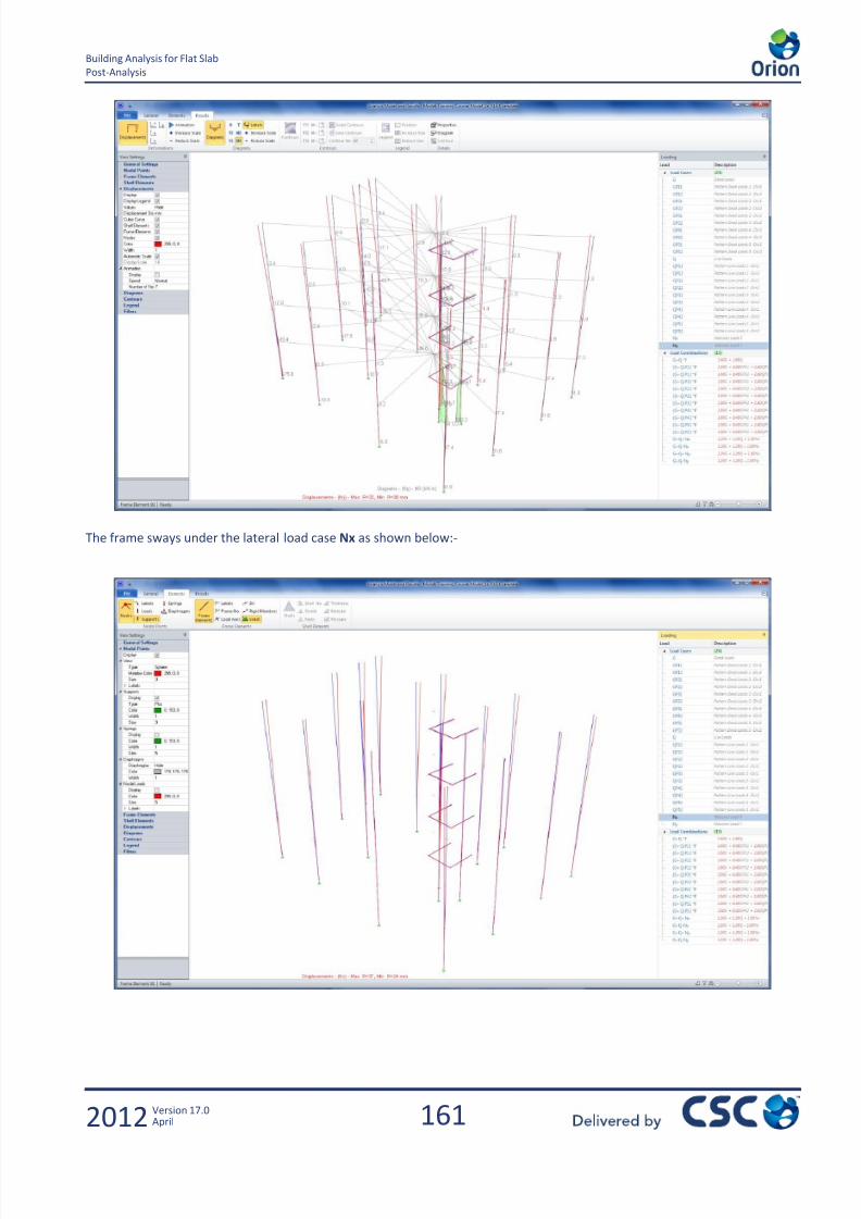
7/22/2019 Standard Training Manual
http://slidepdf.com/reader/full/standard-training-manual 162/286
161
Building Analysis for Flat Slab
Post-Analysis
2012 Version 17.0April
The frame sways under the lateral load case Nx as shown below:-

7/22/2019 Standard Training Manual
http://slidepdf.com/reader/full/standard-training-manual 163/286

7/22/2019 Standard Training Manual
http://slidepdf.com/reader/full/standard-training-manual 164/286

7/22/2019 Standard Training Manual
http://slidepdf.com/reader/full/standard-training-manual 165/286
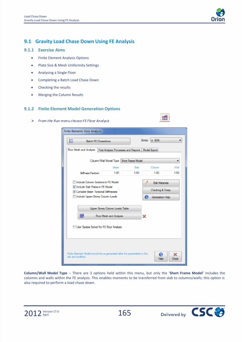
7/22/2019 Standard Training Manual
http://slidepdf.com/reader/full/standard-training-manual 166/286
165
Load Chase Down
Gravity Load Chase Down Using FE Analysis
2012 Version 17.0April
9.1 Gravity Load Chase Down Using FE Analysis
9.1.1 Exercise Aims
Finite Element Analysis Options
Plate Size & Mesh Uniformity Settings
Analysing a Single Floor
Completing a Batch Load Chase Down
Checking the results
Merging the Column Results
9.1.2 Finite Element Model Generation Options
From the Run menu choose FE Floor Analysis .
Column/Wall Model Type – There are 3 options held within this menu, but only the ‘Short Frame Model’ includes the
columns and walls within the FE analysis. This enables moments to be transferred from slab to columns/walls; this option is
also required to perform a load chase down.

7/22/2019 Standard Training Manual
http://slidepdf.com/reader/full/standard-training-manual 167/286
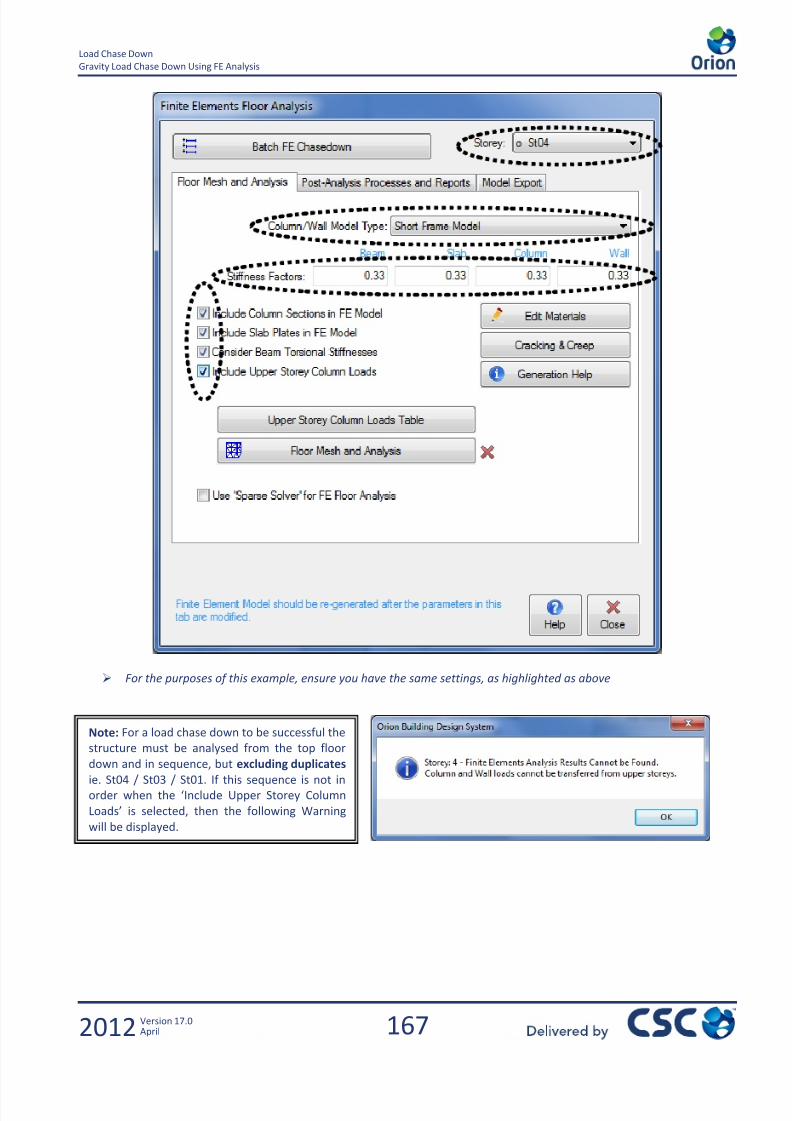
7/22/2019 Standard Training Manual
http://slidepdf.com/reader/full/standard-training-manual 168/286
167
Load Chase Down
Gravity Load Chase Down Using FE Analysis
2012 Version 17.0April
For the purposes of this example, ensure you have the same settings, as highlighted as above
Note: For a load chase down to be successful the
structure must be analysed from the top floor
down and in sequence, but excluding duplicates ie. St04 / St03 / St01. If this sequence is not in
order when the ‘Include Upper Storey Column
Loads’ is selected, then the following Warning
will be displayed.
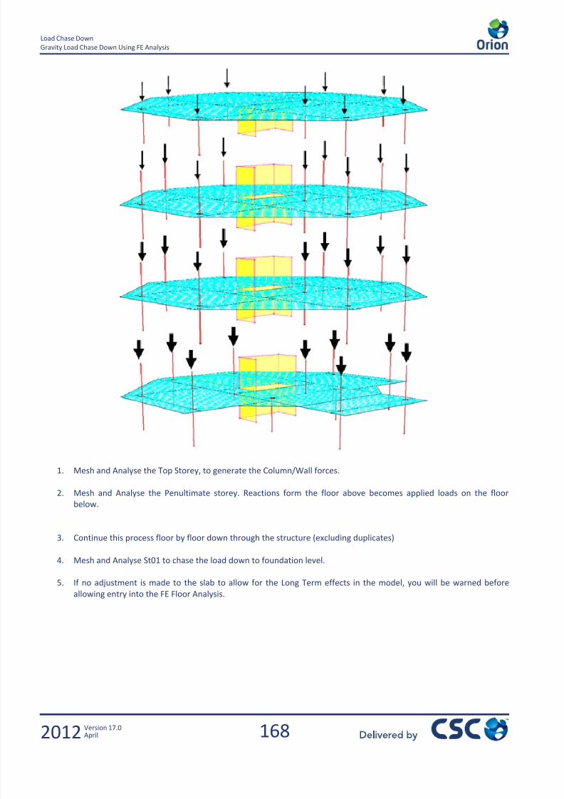
7/22/2019 Standard Training Manual
http://slidepdf.com/reader/full/standard-training-manual 169/286

7/22/2019 Standard Training Manual
http://slidepdf.com/reader/full/standard-training-manual 170/286
169
Load Chase Down
Generating/Performing the FE Analysis Model
2012 Version 17.0April
9.2 Generating/Performing the FE Analysis Model
9.2.1 Creating the FE mesh for Analysis
Ensure you are at Storey St04 and click Floor Mesh and Analysis
Plate Element Size – The smaller the size of the plates, the more plates you have in the model and the longer the analysis will
take. We recommend a minimum of 6-8 plates is achieved between column support locations. The Default plate element size
is 800mm. This is normally sufficient to provide the minimum of 6 plates between supports but it can be increased or
decreased depending on your model.
Mesh Uniformity Factor – The higher the mesh uniformity value, the more equal in area all the plates become, with the
exception around columns for certain locations / geometry. The lower the mesh uniformity factor, the more plates there will
be, and in a much more varied size.
Note: The Stiffness Factors have been altered (0.33) to allow analysis results to be viewed for the Long Term Modulus of
Elasticity (E). Within Orion there are various ways these adjustments can be achieved (though this is the recommended
method) which will affect the results. Therefore, we will no see the above message. These techniques will be discussed
during Day 2 training, or by referring to ‘The Concrete Centre Publication – How to design reinforced concrete flat slabs
using Finite Element Analysis – O Brooker May 2006’
Note: Finite Element Analysis is ONLY used for the determination of Gravity Loads on the structure, hence ONLY G (Dead)
and Q (Imposed), will be available in the Loading pull down menu.

7/22/2019 Standard Training Manual
http://slidepdf.com/reader/full/standard-training-manual 171/286
170
Load Chase Down
Generating/Performing the FE Analysis Model
2012 Version 17.0April
Click Generate Model with 800mm plates and Mesh Uniformity Factor of 25%
This maintains 6-8 plates between a lot of the column locations but may be a bit dense. Note the difference below for Mesh
Uniformity Settings at 100% and 25%. Alternatively, smaller plates could have been used. These settings can have a big
impact on your mesh, and hence results, so you shouldn’t just accept the defaults; always take care to try to obtain the best
mesh possible.
25% Mesh Uniformity Factor 100% Mesh Uniformity Factor
With the floor meshed with 800mm plates and 25% mesh uniformity, close the window for the analysis to complete,
then click back on the Model Preparation tab.
Note: Within the FE model, the plates have been formed around the column heads. This is due to ticking the option
within the FE Analysis Form ‘Include Column Sections in the FE Model’. Although this option allows the physical
dimensions of the columns to be modelled in the FE environment, this does rely upon a more complicated mesh being
formed around the column heads. However, it will potentially give more realistic results as it reduces the peak moments.

7/22/2019 Standard Training Manual
http://slidepdf.com/reader/full/standard-training-manual 172/286
171
Load Chase Down
Generating/Performing the FE Analysis Model
2012 Version 17.0April
9.2.2 Performing the Batch FE Load Chase Down
Left Click on the Batch FE Chasedown
You will see as St04 has already been analysed - A green tick appears beneath the Analysis Status.
Left Click on the Shell Element Size text. Without clicking anywhere else Type 800, then hit Enter.
This will change the plate size for all floor levels to be 800mm. This can be done for all settings in the
Batch FE Chasedown Window.
Ensure the Include Slab Plates in FE Model is ticked on for all floors
Set the Mesh Uniformity Factor to be 25% (25.0)
Ensure Include Column Sections in FE Model is ticked for all floors
Set the Slab and Beam Stiffness Factors to be 0.33 for all floors
Set the Column and Wall Stiffness Coefficients to be 0.33 for all floors
Ensure the Consider Beam Torsional Stiffness is ticked for all floors
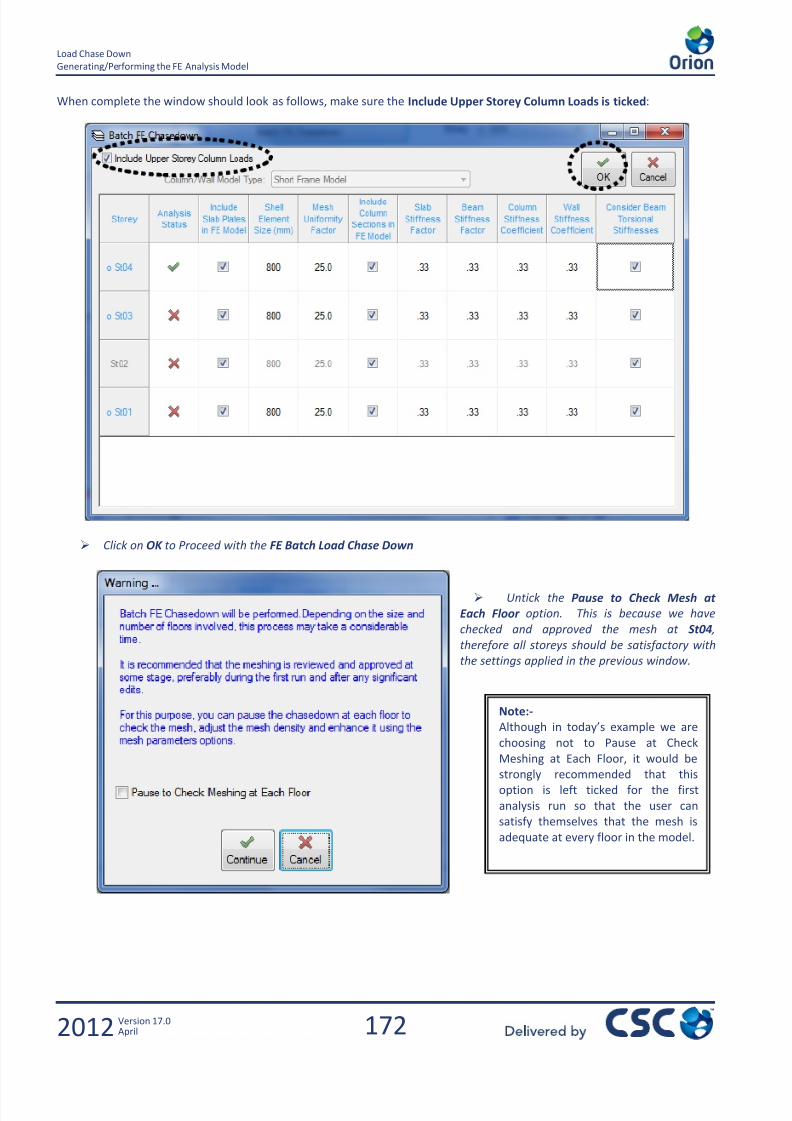
7/22/2019 Standard Training Manual
http://slidepdf.com/reader/full/standard-training-manual 173/286
172
Load Chase Down
Generating/Performing the FE Analysis Model
2012 Version 17.0April
When complete the window should look as follows, make sure the Include Upper Storey Column Loads is ticked:
Click on OK to Proceed with the FE Batch Load Chase Down
Untick the Pause to Check Mesh at
Each Floor option. This is because we have
checked and approved the mesh at St04 ,
therefore all storeys should be satisfactory with
the settings applied in the previous window.
Note:-
Although in today’s example we are
choosing not to Pause at Check
Meshing at Each Floor, it would be
strongly recommended that this
option is left ticked for the first
analysis run so that the user can
satisfy themselves that the mesh is
adequate at every floor in the model.
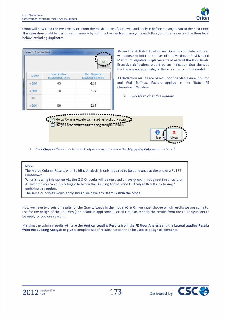
7/22/2019 Standard Training Manual
http://slidepdf.com/reader/full/standard-training-manual 174/286
173
Load Chase Down
Generating/Performing the FE Analysis Model
2012 Version 17.0April
Orion will now Load the Pre Processor, Form the mesh at each floor level, and analyse before moving down to the next floor.
This operation could be performed manually by forming the mesh and analysing each floor, and then selecting the floor level
below, excluding duplicates.
When the FE Batch Load Chase Down is complete a screen
will appear to inform the user of the Maximum Positive and
Maximum Negative Displacements at each of the floor levels.
Excessive deflections would be an indication that the slab
thickness is not adequate, or there is an error in the model.
All deflection results are based upon the Slab, Beam, Column
and Wall Stiffness Factors applied in the ‘Batch FE
Chasedown’ Window.
Click OK to close this window
Click Close in the Finite Element Analysis Form, only when the Merge the Column box is ticked.
Now we have two sets of results for the Gravity Loads in the model (G & Q), we must choose which results we are going to
use for the design of the Columns (and Beams if applicable). For all Flat Slab models the results from the FE Analysis should
be used, for obvious reasons.
Merging the column results will take the Vertical Loading Results from the FE Floor Analysis and the Lateral Loading Results
from the Building Analysis to give a complete set of results that can then be used to design all elements.
Note:
The Merge Column Results with Building Analysis, is only required to be done once at the end of a Full FE
Chasedown.
When choosing this option ALL the G & Q results will be replaced on every level throughout the structure.
At any time you can quickly toggle between the Building Analysis and FE Analysis Results, by ticking /
unticking this option.
The same principles would apply should we have any Beams within the Model.
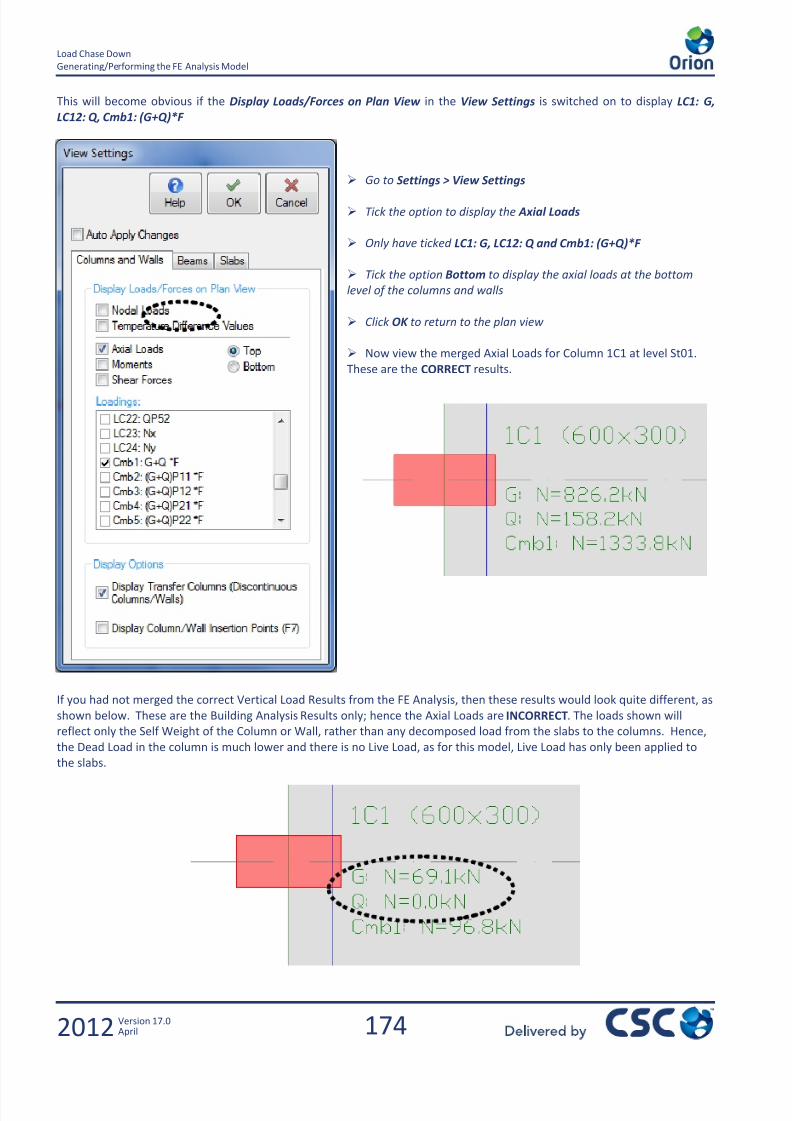
7/22/2019 Standard Training Manual
http://slidepdf.com/reader/full/standard-training-manual 175/286
174
Load Chase Down
Generating/Performing the FE Analysis Model
2012 Version 17.0April
This will become obvious if the Display Loads/Forces on Plan View in the View Settings is switched on to display LC1: G,
LC12: Q, Cmb1: (G+Q)*F
Go to Settings > View Settings
Tick the option to display the Axial Loads
Only have ticked LC1: G, LC12: Q and Cmb1: (G+Q)*F
Tick the option Bottom to display the axial loads at the bottom
level of the columns and walls
Click OK to return to the plan view
Now view the merged Axial Loads for Column 1C1 at level St01.
These are the CORRECT results.
If you had not merged the correct Vertical Load Results from the FE Analysis, then these results would look quite different, as
shown below. These are the Building Analysis Results only; hence the Axial Loads are INCORRECT. The loads shown will
reflect only the Self Weight of the Column or Wall, rather than any decomposed load from the slabs to the columns. Hence,
the Dead Load in the column is much lower and there is no Live Load, as for this model, Live Load has only been applied to
the slabs.

7/22/2019 Standard Training Manual
http://slidepdf.com/reader/full/standard-training-manual 176/286

7/22/2019 Standard Training Manual
http://slidepdf.com/reader/full/standard-training-manual 177/286
176
Load Chase Down
Cross checking the Finite Element Results
2012 Version 17.0April
Below is a quick summary table to compare the results from Tables 1 and 4.
Dead Load (kN) Live Load (kN)
Table 1 (Total Applied Load) 17931.4 4414.7
Table 4 (Total Axial Loads 17894.9 4437.5
Difference 36.5 kN Lost 22.8 kN Gained
Orion calculates the percentage difference between the overall loads applied and the overall reactions, as highlighted above.
As you can see there is only a difference of 0.52%, which is more than acceptable, so we can now move on to the design.
Note:
There will always be a slight variation in Table 1 and Table 4. This is due to the FE analysis being
performed on a centreline model, and therefore slight overlapping of the slabs and the beams/walls will
occur.
There will also be differences due to the fact that the Building Analysis does not include the slab elements,
hence any openings will not be considered within Table 1.Tables 2 & 3 are to be DISREGARDED, as there is no beams in the model for the slab loads to be
decomposed onto, the results in Tables 2 & 3 are meaningless in a Flat Slab Model.

7/22/2019 Standard Training Manual
http://slidepdf.com/reader/full/standard-training-manual 178/286
177
Flat Slab
2012 Version 17.0April
10.0 Flat Slab

7/22/2019 Standard Training Manual
http://slidepdf.com/reader/full/standard-training-manual 179/286
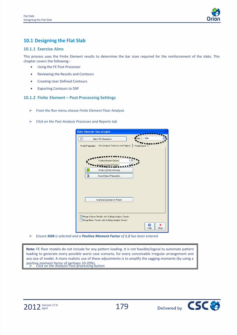
7/22/2019 Standard Training Manual
http://slidepdf.com/reader/full/standard-training-manual 180/286
179
Flat Slab
Designing the Flat Slab
2012 Version 17.0April
10.1 Designing the Flat Slab
10.1.1 Exercise Aims
This process uses the Finite Element results to determine the bar sizes required for the reinforcement of the slabs. Thischapter covers the following:-
Using the FE Post Processor
Reviewing the Results and Contours
Creating User Defined Contours
Exporting Contours to DXF
10.1.2 Finite Element – Post Processing Settings
From the Run menu choose Finite Element Floor Analysis
Click on the Post Analysis Processes and Reports tab
Ensure St04 is selected and a Positive Moment Factor of 1.2 has been entered
Click on the Analysis Post-processing button
Note: FE floor models do not include for any pattern loading. It is not feasible/logical to automate pattern
loading to generate every possible worst case scenario, for every conceivable irregular arrangement and
any size of model. A more realistic use of these adjustments is to amplify the sagging moments (by using a
positive moment factor of perhaps 10-20%).

7/22/2019 Standard Training Manual
http://slidepdf.com/reader/full/standard-training-manual 181/286
180
Flat Slab
Floor Analysis Post Processing
2012 Version 17.0April
10.2 Floor Analysis Post Processing
This takes you through to the Post Processing window.
10.2.1 Deflection Plots
From the Results Ribbon the following buttons allow the display of Displacements and the Contours on the model.
The first option Displacements shows the displacement diagram of the mesh, for the selected storey.

7/22/2019 Standard Training Manual
http://slidepdf.com/reader/full/standard-training-manual 182/286

7/22/2019 Standard Training Manual
http://slidepdf.com/reader/full/standard-training-manual 183/286
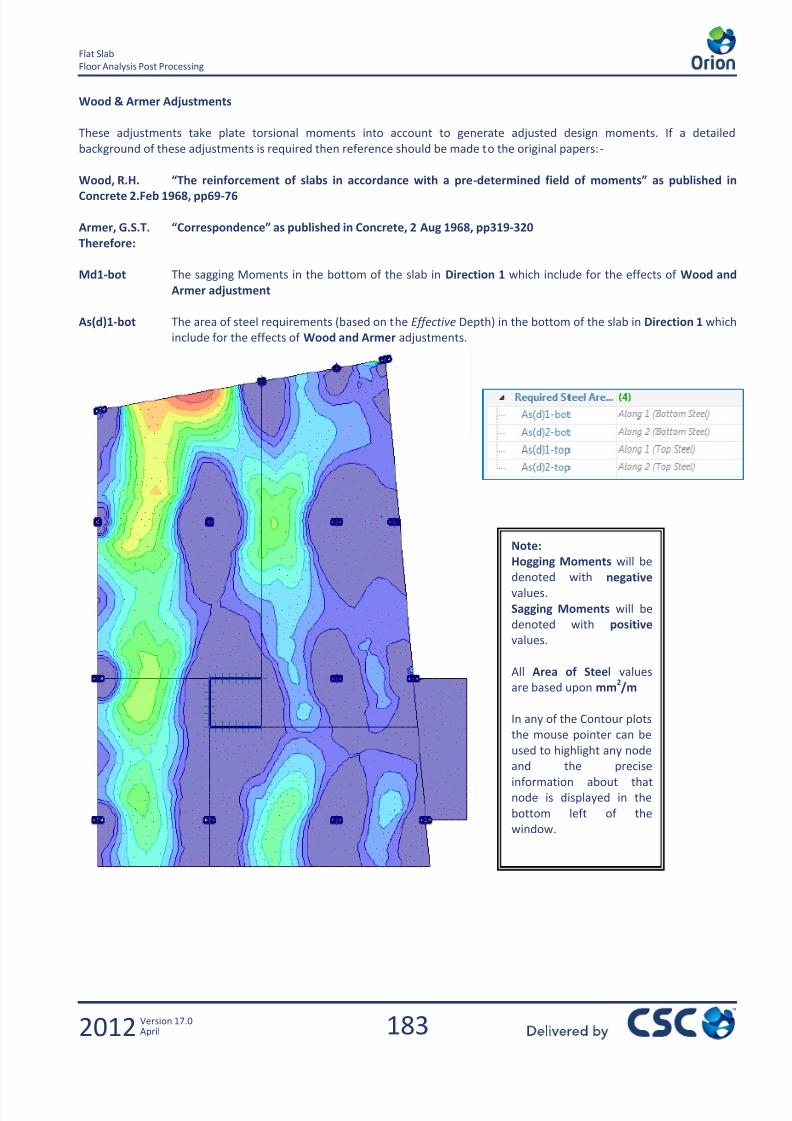
7/22/2019 Standard Training Manual
http://slidepdf.com/reader/full/standard-training-manual 184/286
183
Flat Slab
Floor Analysis Post Processing
2012 Version 17.0April
Note:
Hogging Moments will be
denoted with negativevalues.
Sagging Moments will be
denoted with positive
values.
All Area of Steel values
are based upon mm2/m
In any of the Contour plots
the mouse pointer can be
used to highlight any node
and the preciseinformation about that
node is displayed in the
bottom left of the
window.
Wood & Armer Adjustments
These adjustments take plate torsional moments into account to generate adjusted design moments. If a detailed
background of these adjustments is required then reference should be made to the original papers:-
Wood, R.H. “The reinforcement of slabs in accordance with a pre-determined field of moments” as published in
Concrete 2.Feb 1968, pp69-76
Armer, G.S.T. “Correspondence” as published in Concrete, 2 Aug 1968, pp319-320
Therefore:
Md1-bot The sagging Moments in the bottom of the slab in Direction 1 which include for the effects of Wood and
Armer adjustment
As(d)1-bot The area of steel requirements (based on the Effective Depth) in the bottom of the slab in Direction 1 which
include for the effects of Wood and Armer adjustments.
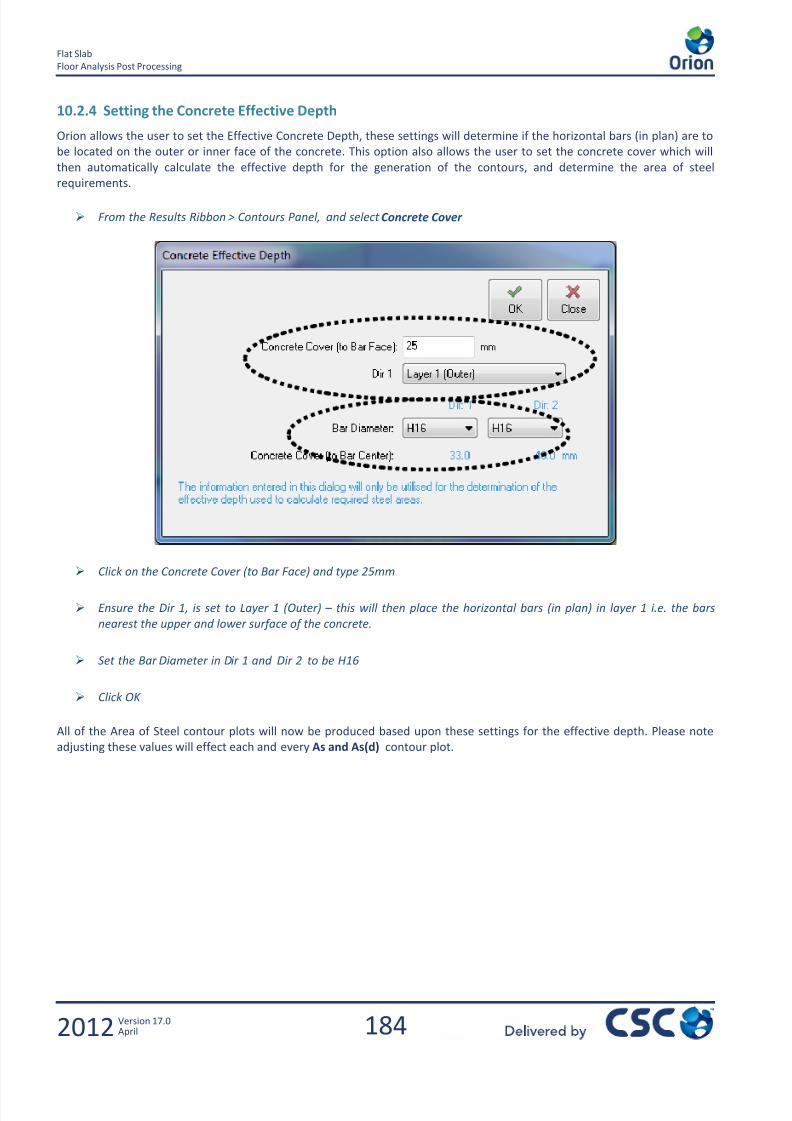
7/22/2019 Standard Training Manual
http://slidepdf.com/reader/full/standard-training-manual 185/286
184
Flat Slab
Floor Analysis Post Processing
2012 Version 17.0April
10.2.4 Setting the Concrete Effective Depth
Orion allows the user to set the Effective Concrete Depth, these settings will determine if the horizontal bars (in plan) are to
be located on the outer or inner face of the concrete. This option also allows the user to set the concrete cover which will
then automatically calculate the effective depth for the generation of the contours, and determine the area of steel
requirements.
From the Results Ribbon > Contours Panel, and select Concrete Cover
Click on the Concrete Cover (to Bar Face) and type 25mm
Ensure the Dir 1, is set to Layer 1 (Outer) – this will then place the horizontal bars (in plan) in layer 1 i.e. the bars
nearest the upper and lower surface of the concrete.
Set the Bar Diameter in Dir 1 and Dir 2 to be H16
Click OK
All of the Area of Steel contour plots will now be produced based upon these settings for the effective depth. Please note
adjusting these values will effect each and every As and As(d) contour plot.

7/22/2019 Standard Training Manual
http://slidepdf.com/reader/full/standard-training-manual 186/286
185
Flat Slab
Floor Analysis Post Processing
2012 Version 17.0April
10.2.5 Bottom Steel Reinforcement Provision
Although Orion has automatically calculated the Area of Steel Requirements, this information does not relate to actual bar
sizes. Therefore we are going to determine the reinforcement in the slab, based on a user defined set of parameters for the
bar sizes.
Click on the Effects Window and select As(d)1-bot
Click on the User Defined Contours in the Results Ribbon
From the Results ribbon > Contours Panel, select Edit Contours
Ensure the Number of Contours is set to 3
Ensure the Legend setting is set to Both
Click Update
If the Re-Interpolate Contour values? Box appears
click Yes
The Min and Max values cannot be altered but the Contours in-between can be used based on actual bar sizes and spacings.
Note:
The pull down menu at the side of the User Defined Contours option allows the user to change the display
settings.
Shaded / Lines / Contour Values can all be switched on or off within this screen, this has no effect on the
model.
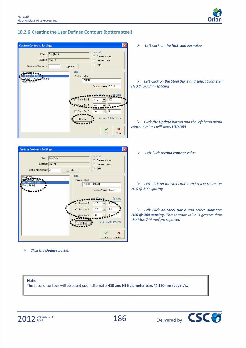
7/22/2019 Standard Training Manual
http://slidepdf.com/reader/full/standard-training-manual 187/286
186
Flat Slab
Floor Analysis Post Processing
2012 Version 17.0April
10.2.6 Creating the User Defined Contours (bottom steel)
Left Click on the first contour value
Left Click on the Steel Bar 1 and select Diameter
H10 @ 300mm spacing
Click the Update button and the left hand menu
contour values will show H10-300
Left Click second contour value
Left Click on the Steel Bar 1 and select Diameter
H10 @ 300 spacing
Left Click on Steel Bar 2 and select Diameter
H16 @ 300 spacing. This contour value is greater than
the Max 744 mm2 /m reported
Click the Update button
Note:
The second contour will be based upon alternate H10 and H16 diameter bars @ 150mm spacing’s.

7/22/2019 Standard Training Manual
http://slidepdf.com/reader/full/standard-training-manual 188/286
187
Flat Slab
Floor Analysis Post Processing
2012 Version 17.0April
Note:
The blue areas in the contour
plot denote where H10 @300mm is sufficient.
The green area of the contour
plot is where H10@300 plus
H16 @ 300mm is required.
IMPORTANT
All contour plots are based
upon exact values, therefore
these plots DO NOT include for
Anchorage Lengths
10.2.7 Creating the User Defined Contours (top steel)
Select As(d)1-top plot from the Effects
Right Click to enter the Contour Settings once again
Ensure the Contours = 4 and the Legend is set to Both and click Update
Set the first contour to be H10 @ 300mm
Set the second contour to be H10 @ 300 plus H20 @ 300mm
Set the third contour to H10 @ 300 plus H20 @ 300 plus H25 @ 300mm
Click the Update button after completing the settings for each contour
Click OK
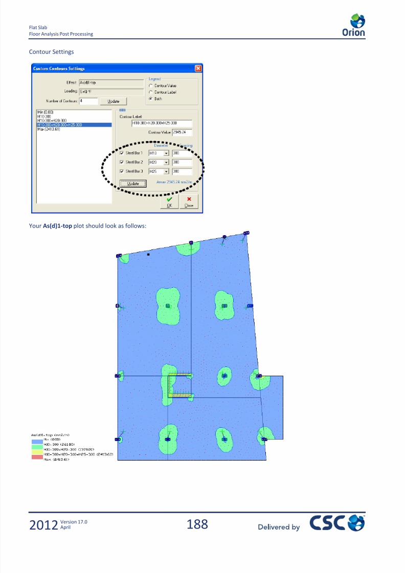
7/22/2019 Standard Training Manual
http://slidepdf.com/reader/full/standard-training-manual 189/286
188
Flat Slab
Floor Analysis Post Processing
2012 Version 17.0April
Contour Settings
Your As(d)1-top plot should look as follows:
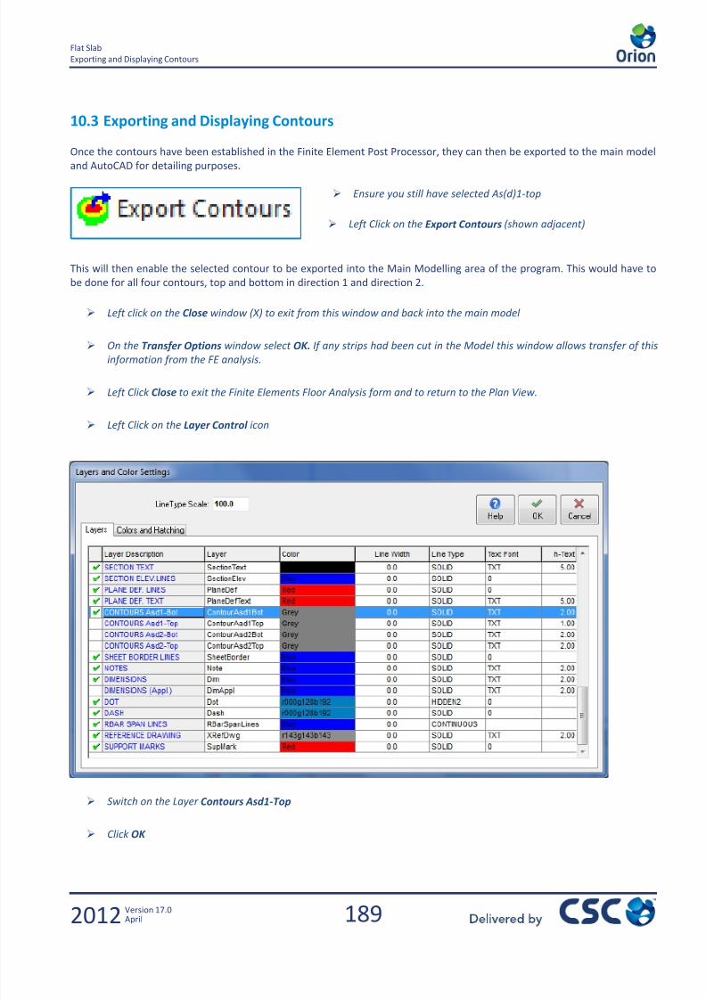
7/22/2019 Standard Training Manual
http://slidepdf.com/reader/full/standard-training-manual 190/286
189
Flat Slab
Exporting and Displaying Contours
2012 Version 17.0April
10.3 Exporting and Displaying Contours
Once the contours have been established in the Finite Element Post Processor, they can then be exported to the main model
and AutoCAD for detailing purposes.
Ensure you still have selected As(d)1-top
Left Click on the Export Contours (shown adjacent)
This will then enable the selected contour to be exported into the Main Modelling area of the program. This would have to
be done for all four contours, top and bottom in direction 1 and direction 2.
Left click on the Close window (X) to exit from this window and back into the main model
On the Transfer Options window select OK. If any strips had been cut in the Model this window allows transfer of this
information from the FE analysis.
Left Click Close to exit the Finite Elements Floor Analysis form and to return to the Plan View.
Left Click on the Layer Control icon
Switch on the Layer Contours Asd1-Top
Click OK
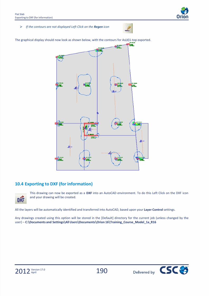
7/22/2019 Standard Training Manual
http://slidepdf.com/reader/full/standard-training-manual 191/286
190
Flat Slab
Exporting to DXF (for information)
2012 Version 17.0April
If the contours are not displayed Left Click on the Regen icon
The graphical display should now look as shown below, with the contours for As(d)1-top exported.
10.4 Exporting to DXF (for information)
This drawing can now be exported as a DXF into an AutoCAD environment. To do this Left Click on the DXF icon
and your drawing will be created.
All the layers will be automatically identified and transferred into AutoCAD, based upon your Layer Control settings.
Any drawings created using this option will be stored in the [Default] directory for the current job (unless changed by the
user) – C:\Documents and Settings\All Users\Documents\Orion 16\Training_Course_Model_1a_R16
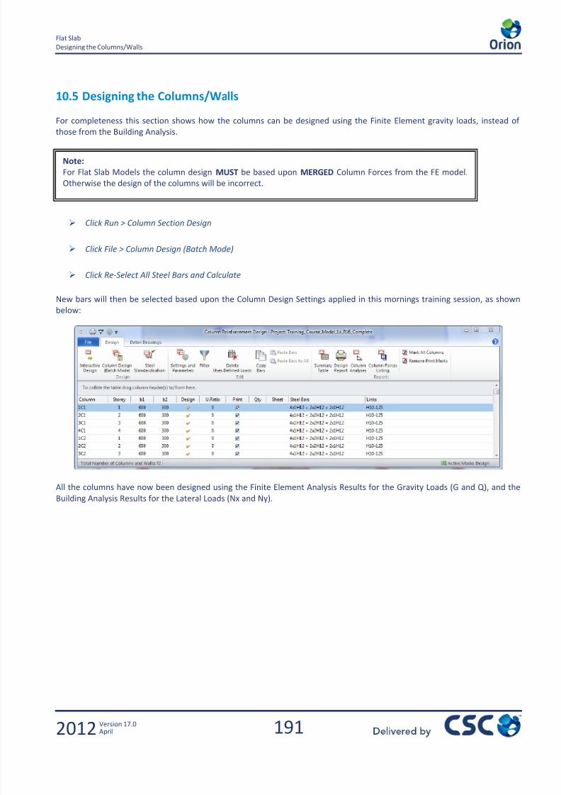
7/22/2019 Standard Training Manual
http://slidepdf.com/reader/full/standard-training-manual 192/286

7/22/2019 Standard Training Manual
http://slidepdf.com/reader/full/standard-training-manual 193/286

7/22/2019 Standard Training Manual
http://slidepdf.com/reader/full/standard-training-manual 194/286
193
Appendix A
Designing the Columns/Walls
2012 Version 17.0April
11.0 Appendix A
Wind Loads

7/22/2019 Standard Training Manual
http://slidepdf.com/reader/full/standard-training-manual 195/286
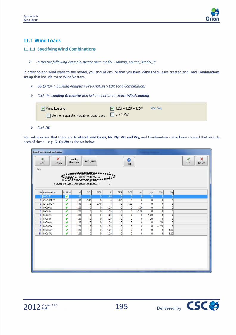
7/22/2019 Standard Training Manual
http://slidepdf.com/reader/full/standard-training-manual 196/286
195
Appendix A
Wind Loads
2012 Version 17.0April
11.1 Wind Loads
11.1.1 Specifying Wind Combinations
To run the following example, please open model ‘Training_Course_Model_1’
In order to add wind loads to the model, you should ensure that you have Wind Load Cases created and Load Combinations
set up that include these Wind Vectors.
Go to Run > Building Analysis > Pre-Analysis > Edit Load Combinations
Click the Loading Generator and tick the option to create Wind Loading
Click OK
You will now see that there are 4 Lateral Load Cases, Nx, Ny, Wx and Wy, and Combinations have been created that include
each of these – e.g. G+Q+Wx as shown below.

7/22/2019 Standard Training Manual
http://slidepdf.com/reader/full/standard-training-manual 197/286
196
Appendix A
Wind Loads
2012 Version 17.0April
11.1.2 Applying a Single Wind Load to Each Floor
Go to Run > Building Analysis > Pre-Analysis > Edit Storey Loads
By clicking on each of the storey labels in the upper table, the Wx and Wy values for each storey can be entered in the lower
table.
The wind loading is entered as a single point load on each storey.
The location of the load is specified by entering its X and Y co-
ordinates. These are measured from (0,0) - NOT from the bottom
left of the model.
The load is transferred to the columns and walls via diaphragm action
within the floor. The diaphragm model is defined on the Model Options
tab of the Analysis form.
CG
Floor Plan
Wy
Wx
Ny
Nx
X
X
0,0
Note: The Notional Horizontal
Loads are applied at the centre of
mass of the floor, whereas the
Wind Loads should be applied at
the centre of the building
elevation. Thus a hand calc may be
necessary to determine the co-
ordinates to the Wind Load
location.

7/22/2019 Standard Training Manual
http://slidepdf.com/reader/full/standard-training-manual 198/286

7/22/2019 Standard Training Manual
http://slidepdf.com/reader/full/standard-training-manual 199/286
198
Appendix A
Wind Loads
2012 Version 17.0April
In direction one.
Centre of elevation is 19800 mm / 2 = 9900 mm
Distance of the centre of elevation from the centre of mass is
9900 mm – 9071 mm = 829 mm
X coordinate is 14.071 m + 0.829 m = 14.900 m
For simplicity assuming 1.0 kN/m2
wind loading
The loading in the Y direction Wy = 19.8 m 4m 1.0 kN/m2 = 79.2 kN
In direction two.
Centre of elevation is 27219 mm / 2 = 13610 mm
Distance of the centre of elevation from the centre of mass is
13610 mm – 12341 mm = 1269 mm
Y coordinate is 17.341 m + 1.269 m = 18.610 m
For simplicity assuming 1.0 kN/m2
wind loading
The loading in the X direction Wx = 27.219 m 4.0m 1.0 kN/m2 = 108.9 kN
Enter Wx, Wy loads and co-ordinates for the storey.
Note: In practice the loadings and coordinates may change due to variations in floor layout and storey heights. For this
example we will assume they are all the same.
Enter loads for the other storeys in a similar manner, and then click OK .
Return to Analysis , check the Building Analysis box and then click on Start. The building should now be analysed for the wind load combinations in addition to the other combinations.

7/22/2019 Standard Training Manual
http://slidepdf.com/reader/full/standard-training-manual 200/286
199
Appendix A
Wind Loads
2012 Version 17.0April
Click on the Post-analysis tab and press the Model and Analysis Results Display button.
Using the settings and Filters you can select a wind case and view the results from that case. Viewing the
deformations clearly shows the twisting effect caused by the offset of the coordinates
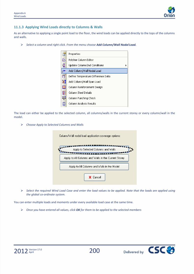
7/22/2019 Standard Training Manual
http://slidepdf.com/reader/full/standard-training-manual 201/286
200
Appendix A
Wind Loads
2012 Version 17.0April
11.1.3 Applying Wind Loads directly to Columns & Walls
As an alternative to applying a single point load to the floor, the wind loads can be applied directly to the tops of the columns
and walls.
Select a column and right click. From the menu choose Add Column/Wall Nodal Load.
The load can either be applied to the selected column, all columns/walls in the current storey or every column/wall in the
model.
Choose Apply to Selected Columns and Walls
Select the required Wind Load Case and enter the load values to be applied. Note that the loads are applied using
the global co-ordinate system.
You can enter multiple loads and moments under every available load case at the same time.
Once you have entered all values, click OK for them to be applied to the selected members

7/22/2019 Standard Training Manual
http://slidepdf.com/reader/full/standard-training-manual 202/286
201
Appendix A
Wind Loads
2012 Version 17.0April

7/22/2019 Standard Training Manual
http://slidepdf.com/reader/full/standard-training-manual 203/286
7/22/2019 Standard Training Manual
http://slidepdf.com/reader/full/standard-training-manual 204/286
203
Appendix B
2012 Version 17.0April
12.0 Appendix B
Beam Design Settings andDetailing

7/22/2019 Standard Training Manual
http://slidepdf.com/reader/full/standard-training-manual 205/286
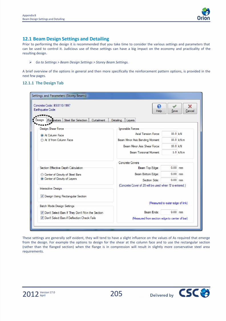
7/22/2019 Standard Training Manual
http://slidepdf.com/reader/full/standard-training-manual 206/286
205
Appendix B
Beam Design Settings and Detailing
2012 Version 17.0April
12.1 Beam Design Settings and DetailingPrior to performing the design it is recommended that you take time to consider the various settings and parameters that
can be used to control it. Judicious use of these settings can have a big impact on the economy and practicality of the
resulting design.
Go to Settings > Beam Design Settings > Storey Beam Settings.
A brief overview of the options in general and then more specifically the reinforcement pattern options, is provided in the
next few pages.
12.1.1 The Design Tab
These settings are generally self evident, they will tend to have a slight influence on the values of As required that emerge
from the design. For example the options to design for the shear at the column face and to use the rectangular section
(rather than the flanged section) when the flange is in compression will result in slightly more conservative steel area
requirements.
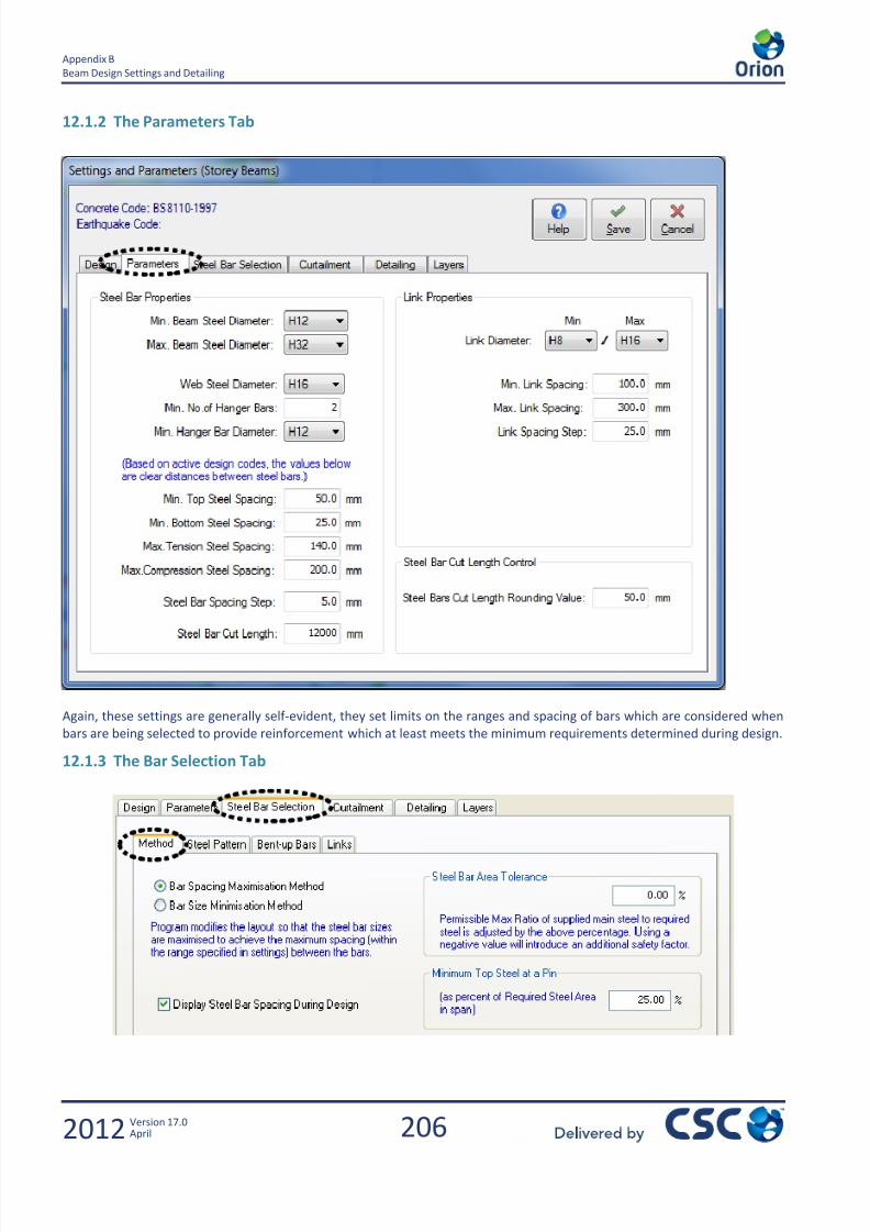
7/22/2019 Standard Training Manual
http://slidepdf.com/reader/full/standard-training-manual 207/286
206
Appendix B
Beam Design Settings and Detailing
2012 Version 17.0April
12.1.2 The Parameters Tab
Again, these settings are generally self-evident, they set limits on the ranges and spacing of bars which are considered when
bars are being selected to provide reinforcement which at least meets the minimum requirements determined during design.
12.1.3 The Bar Selection Tab
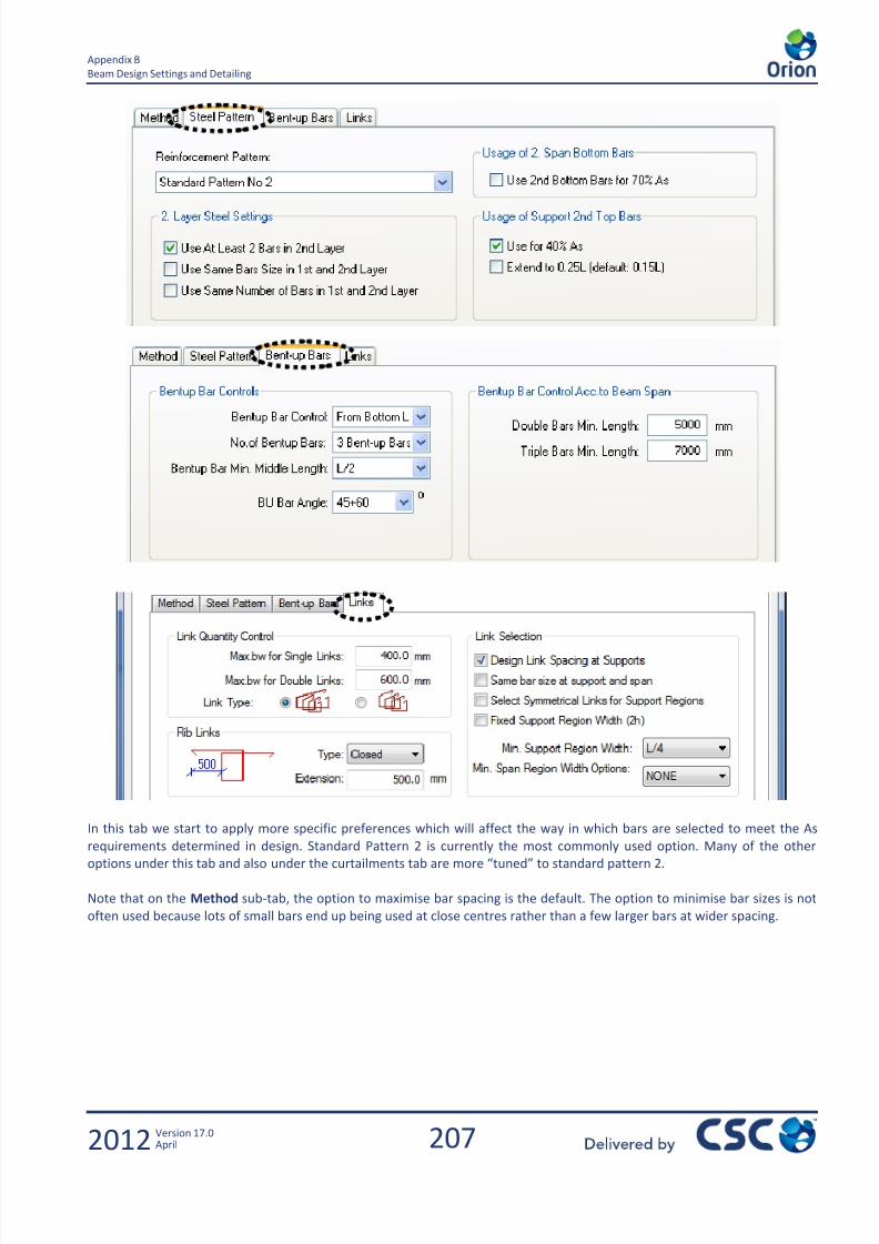
7/22/2019 Standard Training Manual
http://slidepdf.com/reader/full/standard-training-manual 208/286
207
Appendix B
Beam Design Settings and Detailing
2012 Version 17.0April
In this tab we start to apply more specific preferences which will affect the way in which bars are selected to meet the As
requirements determined in design. Standard Pattern 2 is currently the most commonly used option. Many of the otheroptions under this tab and also under the curtailments tab are more “tuned” to standard pattern 2.
Note that on the Method sub-tab, the option to maximise bar spacing is the default. The option to minimise bar sizes is not
often used because lots of small bars end up being used at close centres rather than a few larger bars at wider spacing.

7/22/2019 Standard Training Manual
http://slidepdf.com/reader/full/standard-training-manual 209/286
208
Appendix B
Beam Design Settings and Detailing
2012 Version 17.0April
12.1.4 The Curtailment Tab
In this tab we apply preferences as to how the reinforcement is curtailed. Although this is not under the “detailing” tab, these
sorts of preferences are more traditionally applied by the detailer rather than the designer.
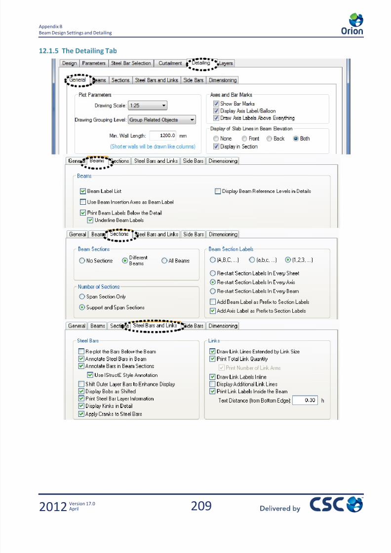
7/22/2019 Standard Training Manual
http://slidepdf.com/reader/full/standard-training-manual 210/286
209
Appendix B
Beam Design Settings and Detailing
2012 Version 17.0April
12.1.5 The Detailing Tab

7/22/2019 Standard Training Manual
http://slidepdf.com/reader/full/standard-training-manual 211/286

7/22/2019 Standard Training Manual
http://slidepdf.com/reader/full/standard-training-manual 212/286
211
Appendix B
Beam Design Settings and Detailing
2012 Version 17.0April
Go to Sheet > Sheet Layout
To bring the beams on a particular axis onto the drawing sheet, perform the following steps.
Position the cursor on the beam axis in the Axis column
Left click and hold on the axis name and then drag the beam onto the sheet
Position the beam where it is to be placed then release the left mouse button.
To manipulate the beam position click and drag the beam around the sheet
To sort according to the storeys, Select Settings and then select Storey.
Repeat this process for some more of the axes so your screen looks similar to below.
Now insert the reinforcement quantity table for these beams on Sheet 1
Select the Schedule button so the following dialog box appears.
Now select OK
The Schedule is now placed at the bottom right of the Sheet 1.
Save this sheet 1 layout by selecting Save.
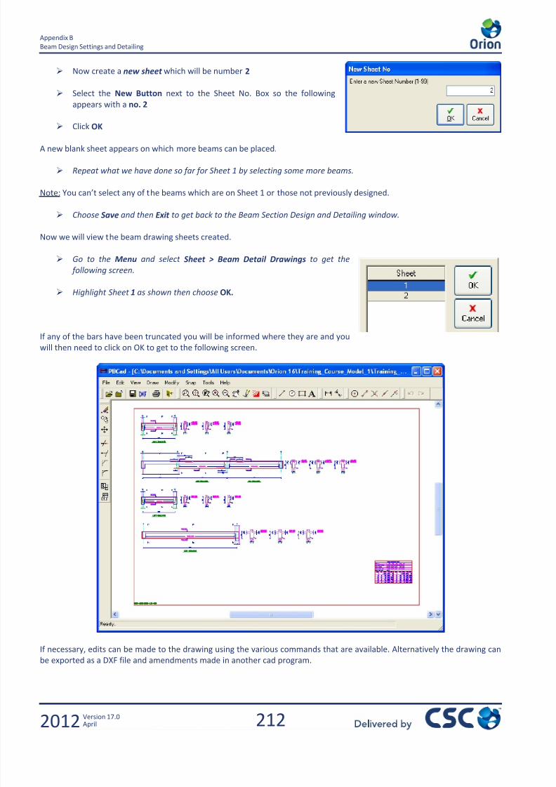
7/22/2019 Standard Training Manual
http://slidepdf.com/reader/full/standard-training-manual 213/286
212
Appendix B
Beam Design Settings and Detailing
2012 Version 17.0April
Now create a new sheet which will be number 2
Select the New Button next to the Sheet No. Box so the following
appears with a no. 2
Click OK
A new blank sheet appears on which more beams can be placed.
Repeat what we have done so far for Sheet 1 by selecting some more beams.
Note: You can’t select any of the beams which are on Sheet 1 or those not previously designed.
Choose Save and then Exit to get back to the Beam Section Design and Detailing window.
Now we will view the beam drawing sheets created.
Go to the Menu and select Sheet > Beam Detail Drawings to get the
following screen.
Highlight Sheet 1 as shown then choose OK.
If any of the bars have been truncated you will be informed where they are and you
will then need to click on OK to get to the following screen.
If necessary, edits can be made to the drawing using the various commands that are available. Alternatively the drawing can
be exported as a DXF file and amendments made in another cad program.

7/22/2019 Standard Training Manual
http://slidepdf.com/reader/full/standard-training-manual 214/286
213
Appendix C
Beam Design Settings and Detailing
2012 Version 17.0April
13.0 Appendix C

7/22/2019 Standard Training Manual
http://slidepdf.com/reader/full/standard-training-manual 215/286
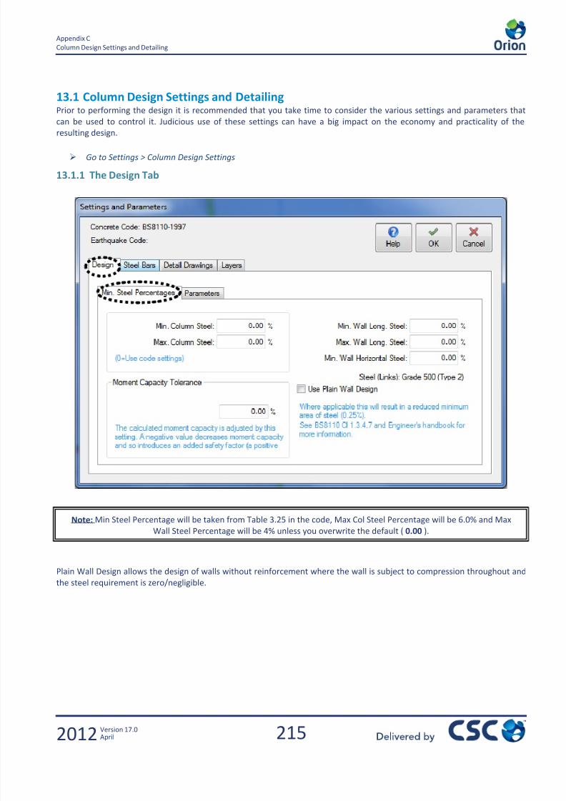
7/22/2019 Standard Training Manual
http://slidepdf.com/reader/full/standard-training-manual 216/286
215
Appendix C
Column Design Settings and Detailing
2012 Version 17.0April
13.1 Column Design Settings and DetailingPrior to performing the design it is recommended that you take time to consider the various settings and parameters that
can be used to control it. Judicious use of these settings can have a big impact on the economy and practicality of the
resulting design.
Go to Settings > Column Design Settings
13.1.1 The Design Tab
Plain Wall Design allows the design of walls without reinforcement where the wall is subject to compression throughout and
the steel requirement is zero/negligible.
Note: Min Steel Percentage will be taken from Table 3.25 in the code, Max Col Steel Percentage will be 6.0% and Max
Wall Steel Percentage will be 4% unless you overwrite the default ( 0.00 ).

7/22/2019 Standard Training Manual
http://slidepdf.com/reader/full/standard-training-manual 217/286
216
Appendix C
Column Design Settings and Detailing
2012 Version 17.0April
By default Orion is set to use the BS8110 method for bi-axial design, however an alternative true bi-axial approach is
available. This latter method can produce some economy; however it is perhaps best thought of as a means to occasionally
fine tune a BS8110 design. You may decide to design using the true bi-axial method and then check the reinforcement using
the BS8110 method. Clause 3.8.4.4. is the more conservative. However, if cl 3.8.4.3 is appropriate, less conservative results
can be achieved.
13.1.2 The Steel Bars Tab
These settings are fairly self explanatory; however some consideration should be given towards the selection of appropriate
lateral steel.
Details of the ‘Steel Bar Selection Method’ are displayed in the blue text below the setting. The option to maximise bar
spacing is the default. This option reduces the congestion compared to the option to minimise bar sizes.
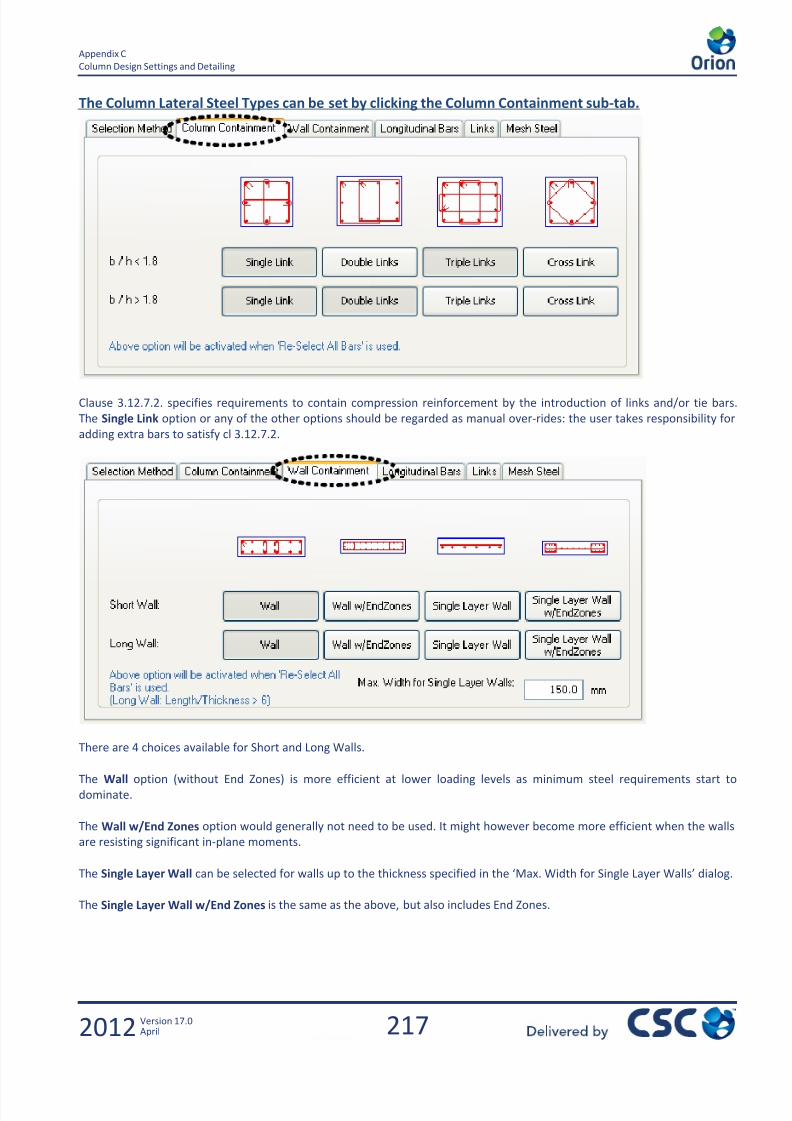
7/22/2019 Standard Training Manual
http://slidepdf.com/reader/full/standard-training-manual 218/286
217
Appendix C
Column Design Settings and Detailing
2012 Version 17.0April
The Column Lateral Steel Types can be set by clicking the Column Containment sub-tab.
Clause 3.12.7.2. specifies requirements to contain compression reinforcement by the introduction of links and/or tie bars.
The Single Link option or any of the other options should be regarded as manual over-rides: the user takes responsibility for
adding extra bars to satisfy cl 3.12.7.2.
There are 4 choices available for Short and Long Walls.
The Wall option (without End Zones) is more efficient at lower loading levels as minimum steel requirements start to
dominate.
The Wall w/End Zones option would generally not need to be used. It might however become more efficient when the walls
are resisting significant in-plane moments.
The Single Layer Wall can be selected for walls up to the thickness specified in the ‘Max. Width for Single Layer Walls’ dialog.
The Single Layer Wall w/End Zones is the same as the above, but also includes End Zones.

7/22/2019 Standard Training Manual
http://slidepdf.com/reader/full/standard-training-manual 219/286
218
Appendix C
Column Design Settings and Detailing
2012 Version 17.0April
The settings on this tab are fairly self explanatory. For example the max bar spacing has been set to 200mm.
Note: Concrete cover 0.00 mm means the amount of cover will be taken from the code, as noted below
the setting in blue. If a non zero value is entered, this will be used instead.

7/22/2019 Standard Training Manual
http://slidepdf.com/reader/full/standard-training-manual 220/286
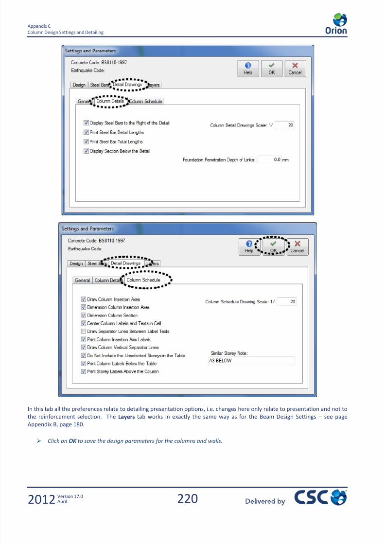
7/22/2019 Standard Training Manual
http://slidepdf.com/reader/full/standard-training-manual 221/286
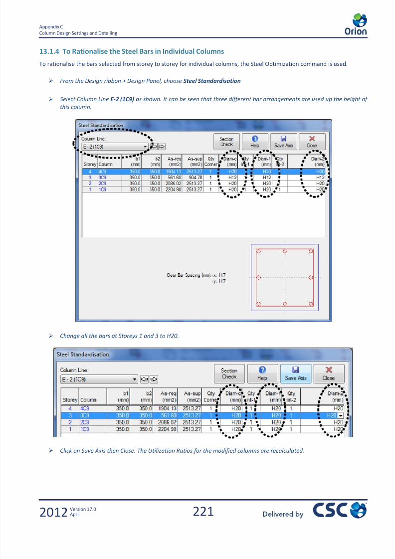
7/22/2019 Standard Training Manual
http://slidepdf.com/reader/full/standard-training-manual 222/286
221
Appendix C
Column Design Settings and Detailing
2012 Version 17.0April
13.1.4 To Rationalise the Steel Bars in Individual Columns
To rationalise the bars selected from storey to storey for individual columns, the Steel Optimization command is used.
From the Design ribbon > Design Panel, choose Steel Standardisation
Select Column Line E-2 (1C9) as shown. It can be seen that three different bar arrangements are used up the height of
this column.
Change all the bars at Storeys 1 and 3 to H20.
Click on Save Axis then Close. The Utilization Ratios for the modified columns are recalculated.
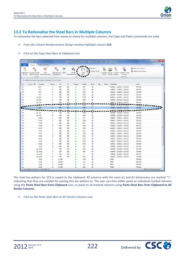
7/22/2019 Standard Training Manual
http://slidepdf.com/reader/full/standard-training-manual 223/286
222
Appendix C
To Rationalise the Steel Bars in Multiple Columns
2012 Version 17.0April
13.2 To Rationalise the Steel Bars in Multiple ColumnsTo rationalise the bars selected from storey to storey for multiple columns, the Copy and Paste commands are used.
From the Column Reinforcement Design window highlight column 1C9.
Click on the Copy Steel Bars to Clipboard icon
The steel bar pattern for 1C9 is copied to the clipboard. All columns with the same b1 and b2 dimensions are marked “=”
indicating that they are suitable for pasting this bar pattern to. The user can then either paste to individual marked columns
using the Paste Steel Bars from Clipboard icon, or paste to all marked columns using Paste Steel Bars from Clipboard to AllSimilar Columns.
Click on the Paste Steel Bars to All Similar Columns icon

7/22/2019 Standard Training Manual
http://slidepdf.com/reader/full/standard-training-manual 224/286
223
Appendix C
Creating the Column Detail Drawings
2012 Version 17.0April
13.3 Creating the Column Detail Drawings Left click and highlight the column you wish to produce a ‘Detail Drawing’ for:
From within the Column Reinforcement Design window select the Detail of Selected Column icon
The Column Axes List option will create a drawing of a single column by clicking on the Draw icon.
If multiple columns are required on the same drawing sheet, the Sheet List option should be used as follows.
Go to Create Sheet Panel > Create Sheets.
Note: It is possible to paste a steel bar pattern that is insufficient. If you do this, the Design status will indicate fail for
those columns and will be shown as such in the Design status. These could be re-designed interactively.
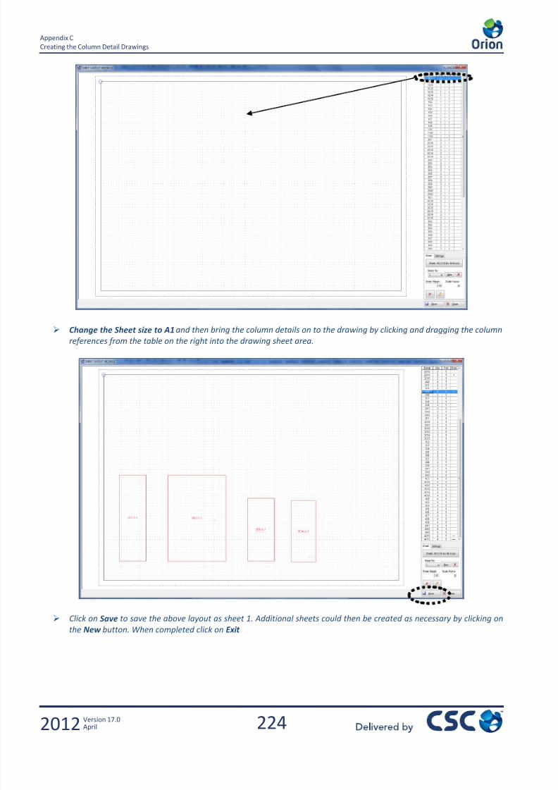
7/22/2019 Standard Training Manual
http://slidepdf.com/reader/full/standard-training-manual 225/286
224
Appendix C
Creating the Column Detail Drawings
2012 Version 17.0April
Change the Sheet size to A1 and then bring the column details on to the drawing by clicking and dragging the column
references from the table on the right into the drawing sheet area.
Click on Save to save the above layout as sheet 1. Additional sheets could then be created as necessary by clicking on
the New button. When completed click on Exit

7/22/2019 Standard Training Manual
http://slidepdf.com/reader/full/standard-training-manual 226/286

7/22/2019 Standard Training Manual
http://slidepdf.com/reader/full/standard-training-manual 227/286

7/22/2019 Standard Training Manual
http://slidepdf.com/reader/full/standard-training-manual 228/286
227
Appendix D
Creating the Column Detail Drawings
2012 Version 17.0April
14.0 Appendix D
Foundation Design

7/22/2019 Standard Training Manual
http://slidepdf.com/reader/full/standard-training-manual 229/286

7/22/2019 Standard Training Manual
http://slidepdf.com/reader/full/standard-training-manual 230/286
229
Appendix D
Foundation Design
2012 Version 17.0April
14.1 Foundation Design
14.1.1 Introduction
This chapter covers the following: Design of a Pad Footing
Design of a Strip Footing
Design of a Raft
14.1.2 Foundation Design Settings
The Allowable Stress of Soil and the Coefficient of Subgrade Reaction are set in the Buildings Menu > Parameters –
Foundations tab.
Some further, more detailed, preferences are set in Setting > Foundation Design Settings.
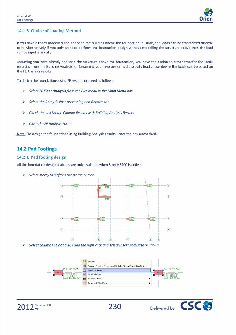
7/22/2019 Standard Training Manual
http://slidepdf.com/reader/full/standard-training-manual 231/286
230
Appendix D
Pad Footings
2012 Version 17.0April
14.1.3 Choice of Loading Method
If you have already modelled and analysed the building above the foundation in Orion, the loads can be transferred directly
to it. Alternatively if you only want to perform the foundation design without modelling the structure above then the load
can be input manually.
Assuming you have already analysed the structure above the foundation, you have the option to either transfer the loads
resulting from the Building Analysis, or (assuming you have performed a gravity load chase-down) the loads can be based on
the FE Analysis results.
To design the foundations using FE results, proceed as follows:
Select FE Floor Analysis from the Run menu in the Main Menu bar.
Select the Analysis Post-processing and Reports tab
Check the box Merge Column Results with Building Analysis Results.
Close the FE Analysis Form.
Note: To design the foundations using Building Analysis results, leave the box unchecked.
14.2 Pad Footings
14.2.1 Pad footing design
All the foundation design features are only available when Storey ST00 is active.
Select storey ST00 from the structure tree.
Select columns 1C2 and 1C3 and the right click and select Insert Pad Base as shown
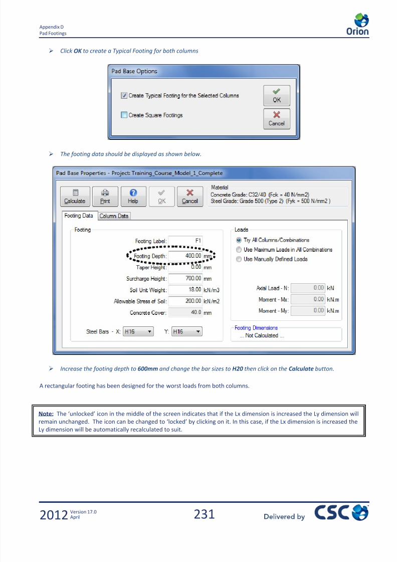
7/22/2019 Standard Training Manual
http://slidepdf.com/reader/full/standard-training-manual 232/286
231
Appendix D
Pad Footings
2012 Version 17.0April
Click OK to create a Typical Footing for both columns
The footing data should be displayed as shown below.
Increase the footing depth to 600mm and change the bar sizes to H20 then click on the Calculate button.
A rectangular footing has been designed for the worst loads from both columns.
Note: The ‘unlocked’ icon in the middle of the screen indicates that if the Lx dimension is increased the Ly dimension will
remain unchanged. The icon can be changed to ‘locked’ by clicking on it. In this case, if the Lx dimension is increased the
Ly dimension will be automatically recalculated to suit.
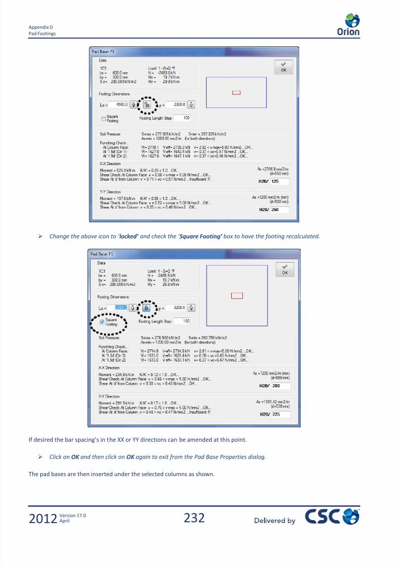
7/22/2019 Standard Training Manual
http://slidepdf.com/reader/full/standard-training-manual 233/286
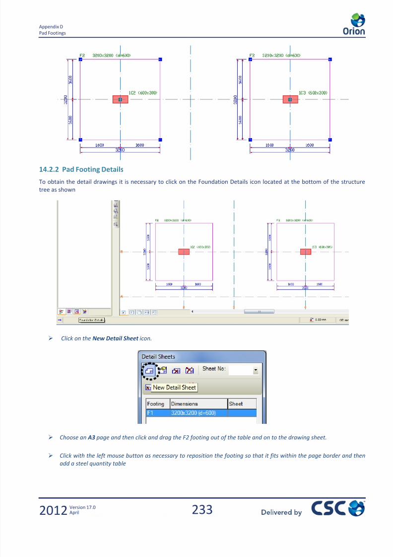
7/22/2019 Standard Training Manual
http://slidepdf.com/reader/full/standard-training-manual 234/286
233
Appendix D
Pad Footings
2012 Version 17.0April
14.2.2 Pad Footing Details
To obtain the detail drawings it is necessary to click on the Foundation Details icon located at the bottom of the structure
tree as shown
Click on the New Detail Sheet icon.
Choose an A3 page and then click and drag the F2 footing out of the table and on to the drawing sheet.
Click with the left mouse button as necessary to reposition the footing so that it fits within the page border and then
add a steel quantity table

7/22/2019 Standard Training Manual
http://slidepdf.com/reader/full/standard-training-manual 235/286
234
Appendix D
Pad Footings
2012 Version 17.0April
To return to the Graphic Editor, click on the Form Plan icon at the base of the structure tree.

7/22/2019 Standard Training Manual
http://slidepdf.com/reader/full/standard-training-manual 236/286
235
Appendix D
Strip Footings
2012 Version 17.0April
14.3 Strip Footings
14.3.1 Strip Footing Design
The Strip Footing is a ‘combined footing’ and can be used in cases where beams connect the columns and/or walls. In cases
where there are no beams between the vertical members, it can still be used but fictitious beams have to be added first
which are of the same depth as the footing. The latter option will be demonstrated.
Create a 600mm wide by 800mm deep beam between columns C1 and C5 , then another between C5 and C8 and a
third between C8 and C12
Select all three newly added beams and then right click and select Insert Strip Footing.
Note: This section of the training manual should only be considered as a brief introduction to the Strip Footing
capabilities of Orion. This subject is much more comprehensively documented in the Engineer’s Handbook.
When designing a strip footing under a continuous wall in which no bending takes place along the major direction of the
wall, the pad footing option can be used. Select the wall, and right click to insert a pad footing.

7/22/2019 Standard Training Manual
http://slidepdf.com/reader/full/standard-training-manual 237/286
236
Appendix D
Strip Footings
2012 Version 17.0April
Checking the Design Envelope box will design the footing for all load combinations.
Select H20 steel diameter and increase the footing depth to 800mm , then click on Design.
Click Calculate and the program works out a required Footing Width and displays a report
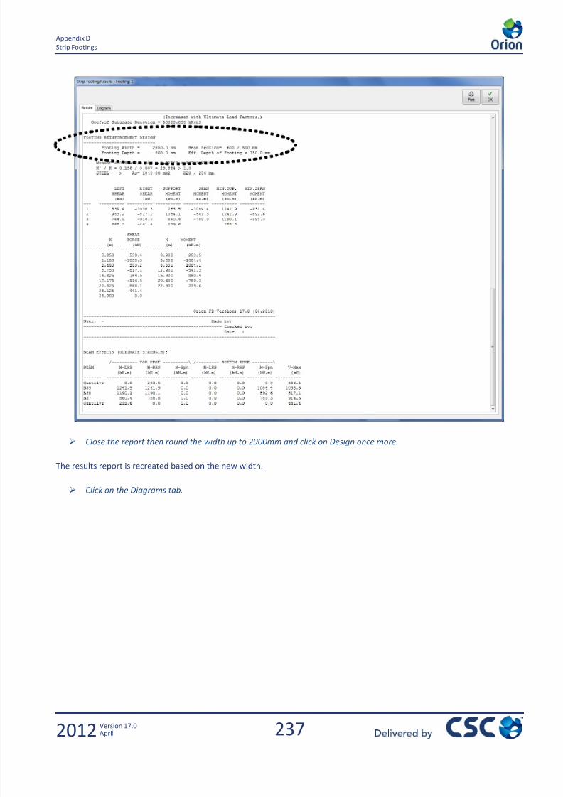
7/22/2019 Standard Training Manual
http://slidepdf.com/reader/full/standard-training-manual 238/286
237
Appendix D
Strip Footings
2012 Version 17.0April
Close the report then round the width up to 2900mm and click on Design once more.
The results report is recreated based on the new width.
Click on the Diagrams tab.
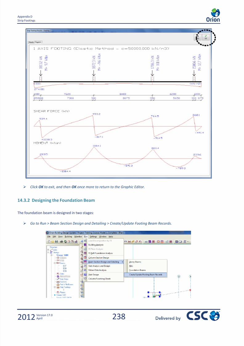
7/22/2019 Standard Training Manual
http://slidepdf.com/reader/full/standard-training-manual 239/286
238
Appendix D
Strip Footings
2012 Version 17.0April
Click OK to exit, and then OK once more to return to the Graphic Editor.
14.3.2 Designing the Foundation Beam
The foundation beam is designed in two stages:
Go to Run > Beam Section Design and Detailing > Create/Update Footing Beam Records.
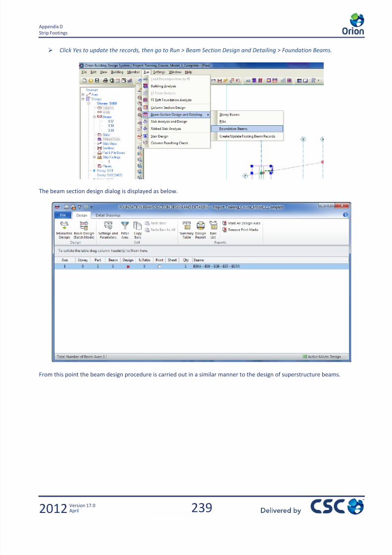
7/22/2019 Standard Training Manual
http://slidepdf.com/reader/full/standard-training-manual 240/286
239
Appendix D
Strip Footings
2012 Version 17.0April
Click Yes to update the records, then go to Run > Beam Section Design and Detailing > Foundation Beams.
The beam section design dialog is displayed as below.
From this point the beam design procedure is carried out in a similar manner to the design of superstructure beams.
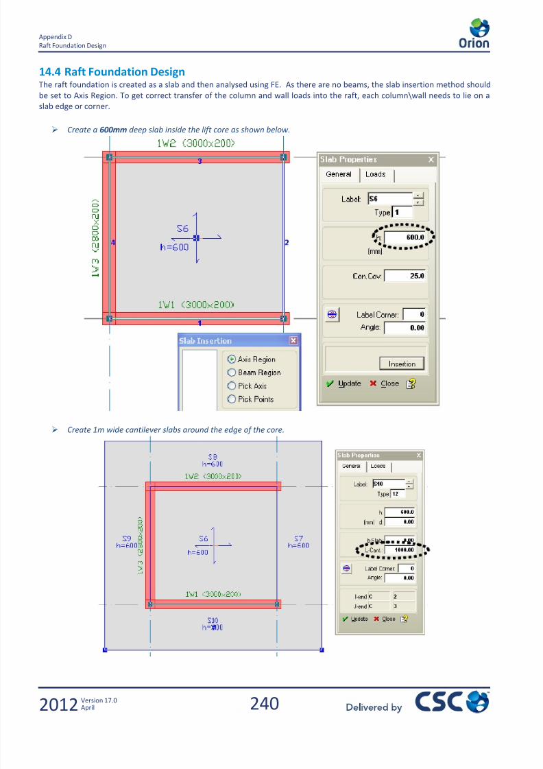
7/22/2019 Standard Training Manual
http://slidepdf.com/reader/full/standard-training-manual 241/286
240
Appendix D
Raft Foundation Design
2012 Version 17.0April
14.4 Raft Foundation DesignThe raft foundation is created as a slab and then analysed using FE. As there are no beams, the slab insertion method should
be set to Axis Region. To get correct transfer of the column and wall loads into the raft, each column\wall needs to lie on a
slab edge or corner.
Create a 600mm deep slab inside the lift core as shown below.
Create 1m wide cantilever slabs around the edge of the core.
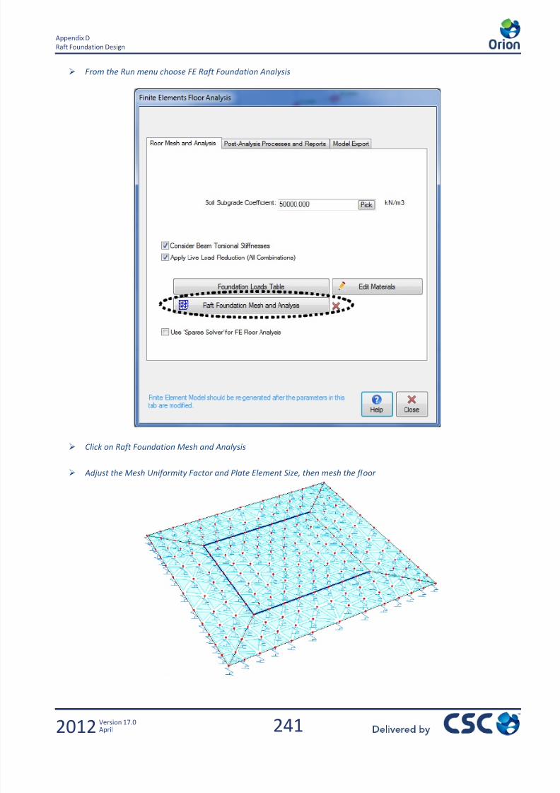
7/22/2019 Standard Training Manual
http://slidepdf.com/reader/full/standard-training-manual 242/286
241
Appendix D
Raft Foundation Design
2012 Version 17.0April
From the Run menu choose FE Raft Foundation Analysis
Click on Raft Foundation Mesh and Analysis
Adjust the Mesh Uniformity Factor and Plate Element Size, then mesh the floor

7/22/2019 Standard Training Manual
http://slidepdf.com/reader/full/standard-training-manual 243/286
242
Appendix D
Raft Foundation Design
2012 Version 17.0April
Exit from the mesh generator and continue with the analysis.
Select the Analysis Post Processing
Display Contour diagrams for the various effects.
Shown below is the Contour diagram for the effect – Soil Pressure Threshold. This indicates that the soil is overstressed. It is
necessary to make the raft larger.
Exit from the Post Processor and then in the graphic editor try increasing the raft size.
Once a satisfactory size has been obtained, reinforcement can be placed in the raft in the same way as was done for the
other FE slabs in the building.

7/22/2019 Standard Training Manual
http://slidepdf.com/reader/full/standard-training-manual 244/286
243
Appendix E
Raft Foundation Design
2012 Version 17.0April
15.0 Appendix E
Loading Combinations and theLoading Generator

7/22/2019 Standard Training Manual
http://slidepdf.com/reader/full/standard-training-manual 245/286
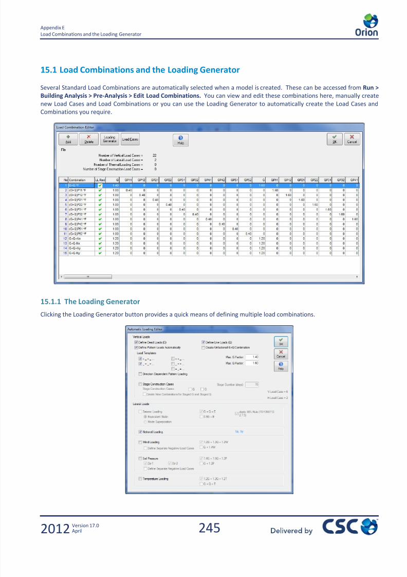
7/22/2019 Standard Training Manual
http://slidepdf.com/reader/full/standard-training-manual 246/286
245
Appendix E
Load Combinations and the Loading Generator
2012 Version 17.0April
15.1 Load Combinations and the Loading Generator
Several Standard Load Combinations are automatically selected when a model is created. These can be accessed from Run >
Building Analysis > Pre-Analysis > Edit Load Combinations. You can view and edit these combinations here, manually createnew Load Cases and Load Combinations or you can use the Loading Generator to automatically create the Load Cases and
Combinations you require.
15.1.1 The Loading Generator
Clicking the Loading Generator button provides a quick means of defining multiple load combinations.
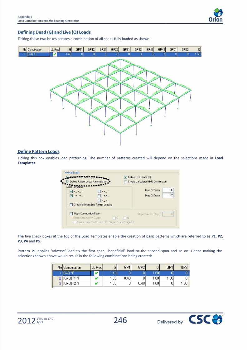
7/22/2019 Standard Training Manual
http://slidepdf.com/reader/full/standard-training-manual 247/286
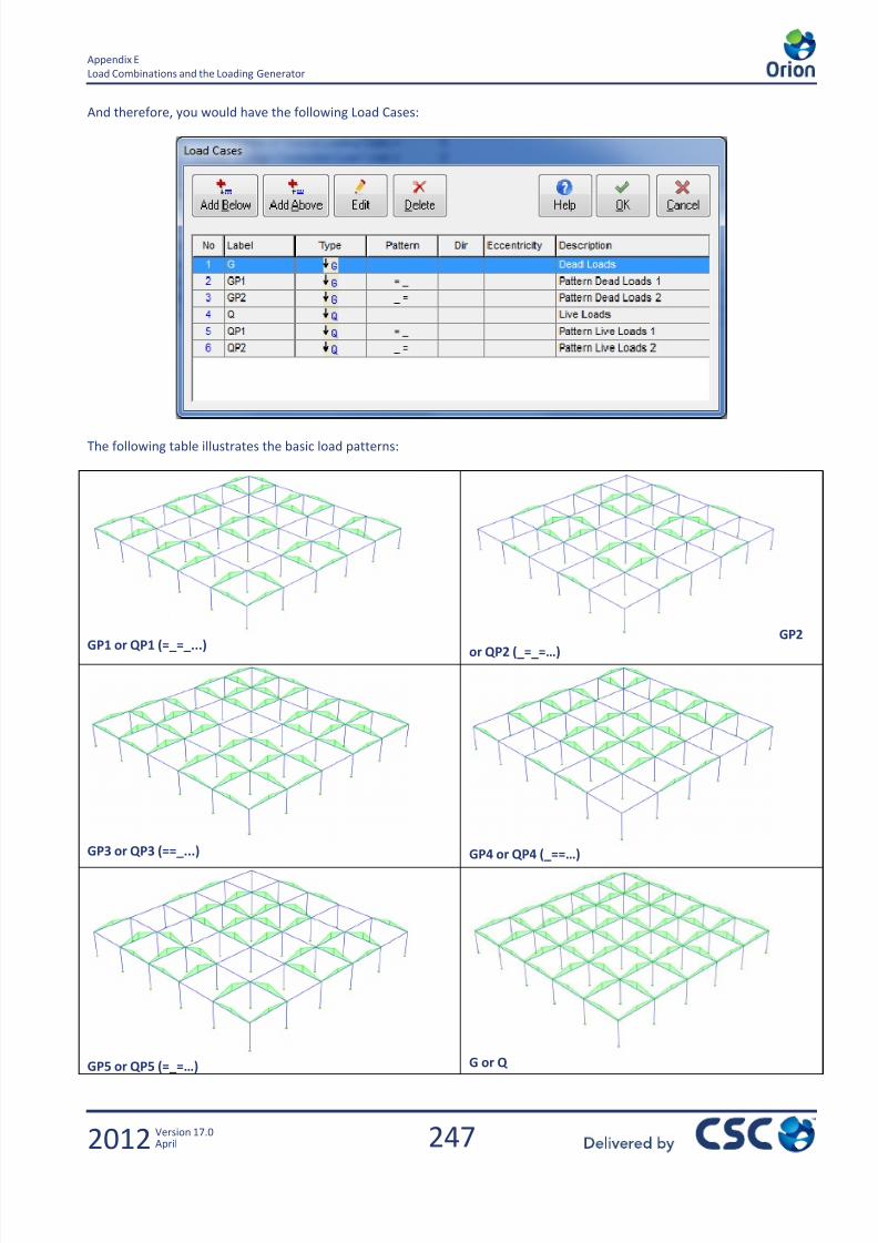
7/22/2019 Standard Training Manual
http://slidepdf.com/reader/full/standard-training-manual 248/286
247
Appendix E
Load Combinations and the Loading Generator
2012 Version 17.0April
And therefore, you would have the following Load Cases:
The following table illustrates the basic load patterns:
GP1 or QP1 (=_=_...) GP2or QP2 (_=_=…)
GP3 or QP3 (==_...) GP4 or QP4 (_==…)
GP5 or QP5 (=_=…) G or Q
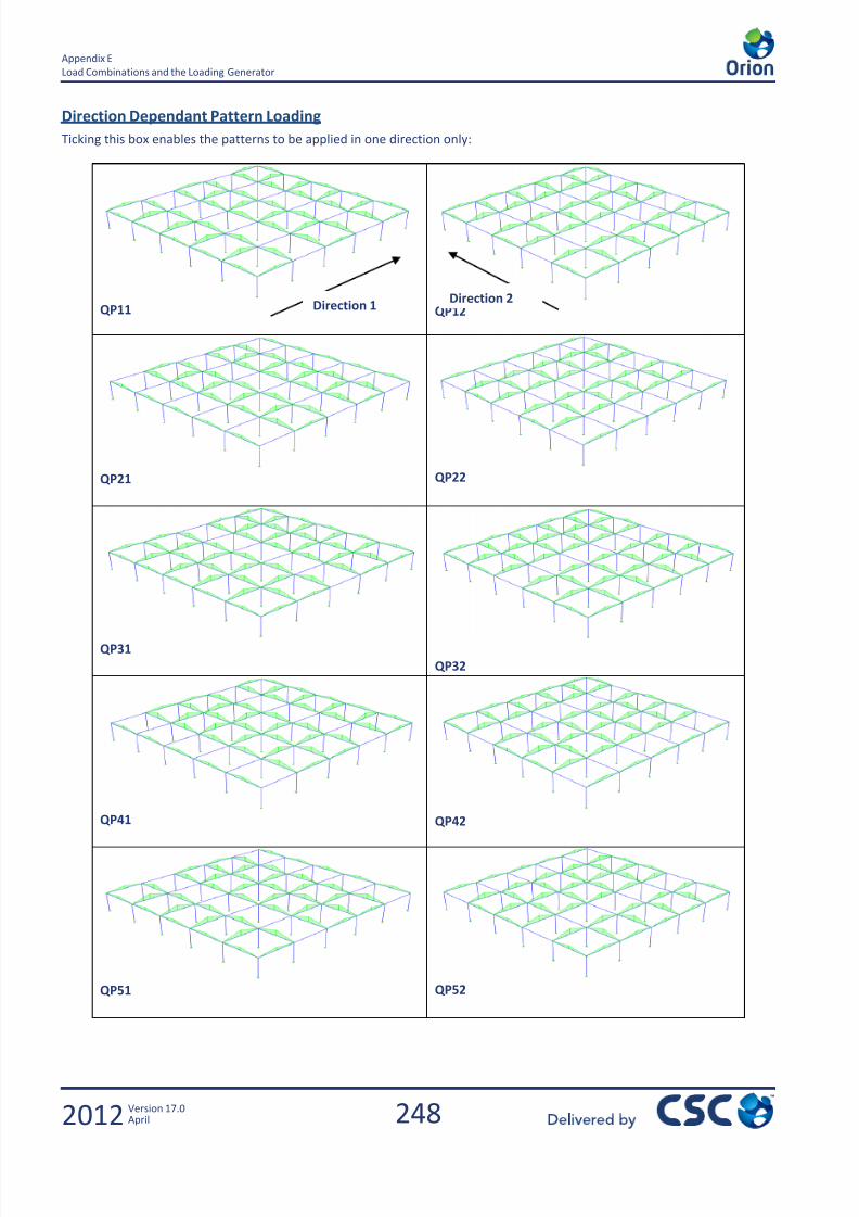
7/22/2019 Standard Training Manual
http://slidepdf.com/reader/full/standard-training-manual 249/286
248
Appendix E
Load Combinations and the Loading Generator
2012 Version 17.0April
Direction Dependant Pattern Loading
Ticking this box enables the patterns to be applied in one direction only:
QP11 QP12
QP21 QP22
QP31
QP32
QP41 QP42
QP51 QP52
Direction 1Direction 2
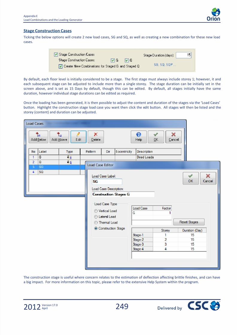
7/22/2019 Standard Training Manual
http://slidepdf.com/reader/full/standard-training-manual 250/286
249
Appendix E
Load Combinations and the Loading Generator
2012 Version 17.0April
Stage Construction Cases
Ticking the below options will create 2 new load cases, SG and SQ, as well as creating a new combination for these new load
cases.
By default, each floor level is initially considered to be a stage. The first stage must always include storey 1; however, it and
each subsequent stage can be adjusted to include more than a single storey. The stage duration can be initially set in the
screen above, and is set as 15 Days by default, though this can be edited. By default, all stages initially have the same
duration, however individual stage durations can be edited as required.
Once the loading has been generated, it is then possible to adjust the content and duration of the stages via the ‘Load Cases’
button. Highlight the construction stage load case you want then click the edit button. All stages will then be listed and the
storey (content) and duration can be adjusted.
The construction stage is useful where concern relates to the estimation of deflection affecting brittle finishes, and can have
a big impact. For more information on this topic, please refer to the extensive Help System within the program.
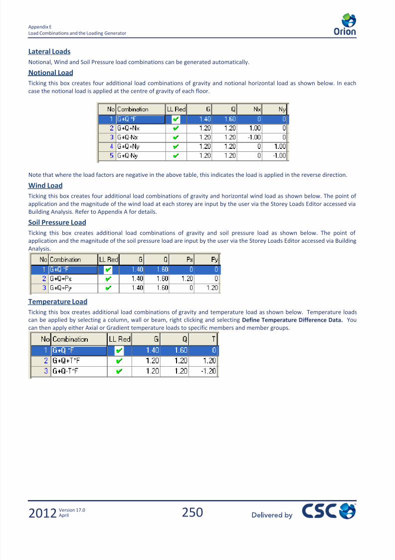
7/22/2019 Standard Training Manual
http://slidepdf.com/reader/full/standard-training-manual 251/286
250
Appendix E
Load Combinations and the Loading Generator
2012 Version 17.0April
Lateral Loads
Notional, Wind and Soil Pressure load combinations can be generated automatically.
Notional Load
Ticking this box creates four additional load combinations of gravity and notional horizontal load as shown below. In each
case the notional load is applied at the centre of gravity of each floor.
Note that where the load factors are negative in the above table, this indicates the load is applied in the reverse direction.
Wind Load
Ticking this box creates four additional load combinations of gravity and horizontal wind load as shown below. The point of
application and the magnitude of the wind load at each storey are input by the user via the Storey Loads Editor accessed via
Building Analysis. Refer to Appendix A for details.
Soil Pressure Load
Ticking this box creates additional load combinations of gravity and soil pressure load as shown below. The point of
application and the magnitude of the soil pressure load are input by the user via the Storey Loads Editor accessed via Building
Analysis.
Temperature Load
Ticking this box creates additional load combinations of gravity and temperature load as shown below. Temperature loads
can be applied by selecting a column, wall or beam, right clicking and selecting Define Temperature Difference Data. You
can then apply either Axial or Gradient temperature loads to specific members and member groups.

7/22/2019 Standard Training Manual
http://slidepdf.com/reader/full/standard-training-manual 252/286
251
Appendix F
2012 Version 17.0April
16.0 Appendix F
Report Manager

7/22/2019 Standard Training Manual
http://slidepdf.com/reader/full/standard-training-manual 253/286

7/22/2019 Standard Training Manual
http://slidepdf.com/reader/full/standard-training-manual 254/286
253
Appendix F
Report Manager
2012 Version 17.0April
16.1 Report Manager
16.1.1 Concrete and Form Estimation Reports
Throughout the training course it has been possible to create individual reports at the various different stages. EG: slabdesign; building analysis; column design; beam design etc.
There are a couple of additional reports that have not been created yet. These will be created here.
From the File menu choose Quantity Extraction Tables
Choose Concrete Quantity Extractions Table and then click Create Report.
View the values then click Report.

7/22/2019 Standard Training Manual
http://slidepdf.com/reader/full/standard-training-manual 255/286
254
Appendix F
Report Manager
2012 Version 17.0April
In the Orion report, click on the Save Report Button then Close and return to the Graphic Editor.
Repeat the process to create a Column/Wall Steel Bar Table and Save this report too.
16.1.2 Report Manager
From the File menu choose Report Manager.
Use the arrows to select those reports that are to be printed as shown.
If connected to a printer the combined report could then be produced.

7/22/2019 Standard Training Manual
http://slidepdf.com/reader/full/standard-training-manual 256/286
255
Appendix G
2012 Version 17.0April
17.0 Appendix G
Polyline Column Editor

7/22/2019 Standard Training Manual
http://slidepdf.com/reader/full/standard-training-manual 257/286
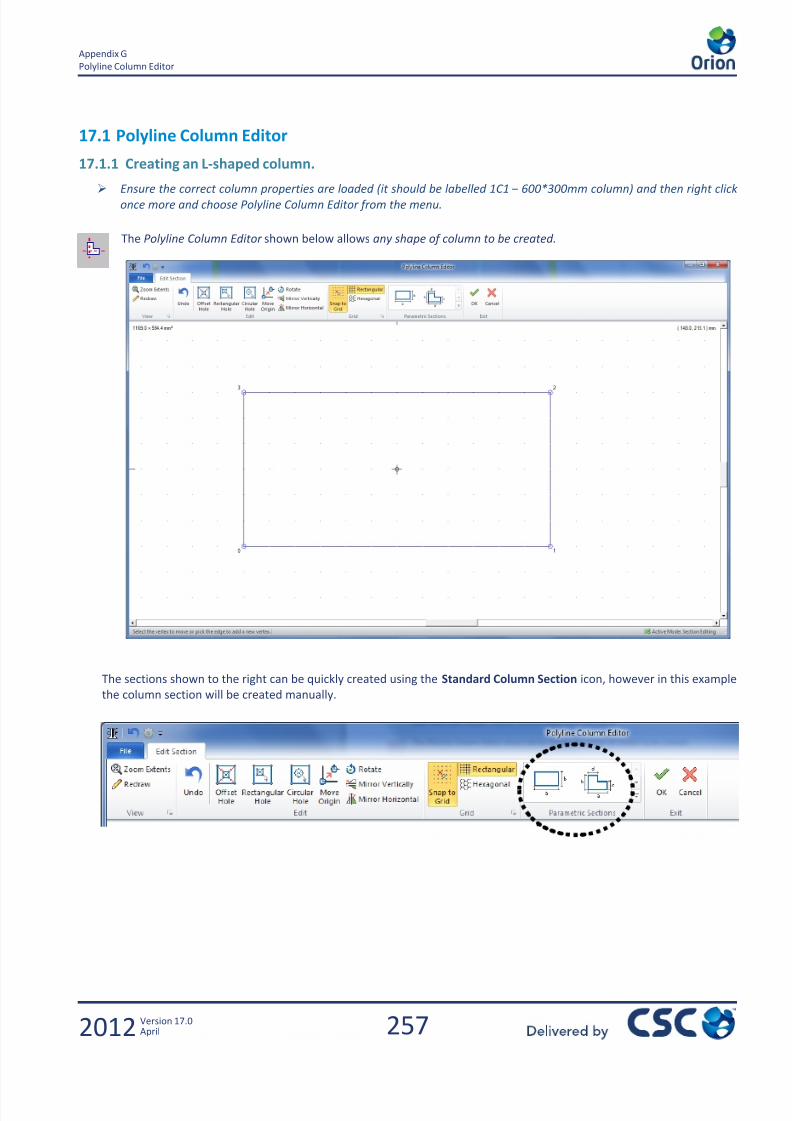
7/22/2019 Standard Training Manual
http://slidepdf.com/reader/full/standard-training-manual 258/286
257
Appendix G
Polyline Column Editor
2012 Version 17.0April
17.1 Polyline Column Editor
17.1.1 Creating an L-shaped column.
Ensure the correct column properties are loaded (it should be labelled 1C1 – 600*300mm column) and then right clickonce more and choose Polyline Column Editor from the menu.
The Polyline Column Editor shown below allows any shape of column to be created.
The sections shown to the right can be quickly created using the Standard Column Section icon, however in this example
the column section will be created manually.
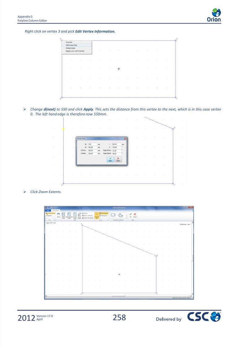
7/22/2019 Standard Training Manual
http://slidepdf.com/reader/full/standard-training-manual 259/286
258
Appendix G
Polyline Column Editor
2012 Version 17.0April
Right click on vertex 3 and pick Edit Vertex Information.
Change d(next) to 550 and click Apply . This sets the distance from this vertex to the next, which is in this case vertex
0. The left hand edge is therefore now 550mm.
Click Zoom Extents.
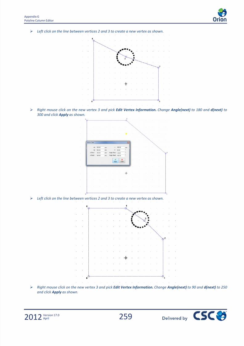
7/22/2019 Standard Training Manual
http://slidepdf.com/reader/full/standard-training-manual 260/286
259
Appendix G
Polyline Column Editor
2012 Version 17.0April
Left click on the line between vertices 2 and 3 to create a new vertex as shown.
Right mouse click on the new vertex 3 and pick Edit Vertex Information. Change Angle(next) to 180 and d(next) to
300 and click Apply as shown.
Left click on the line between vertices 2 and 3 to create a new vertex as shown.
Right mouse click on the new vertex 3 and pick Edit Vertex Information. Change Angle(next) to 90 and d(next) to 250
and click Apply as shown.
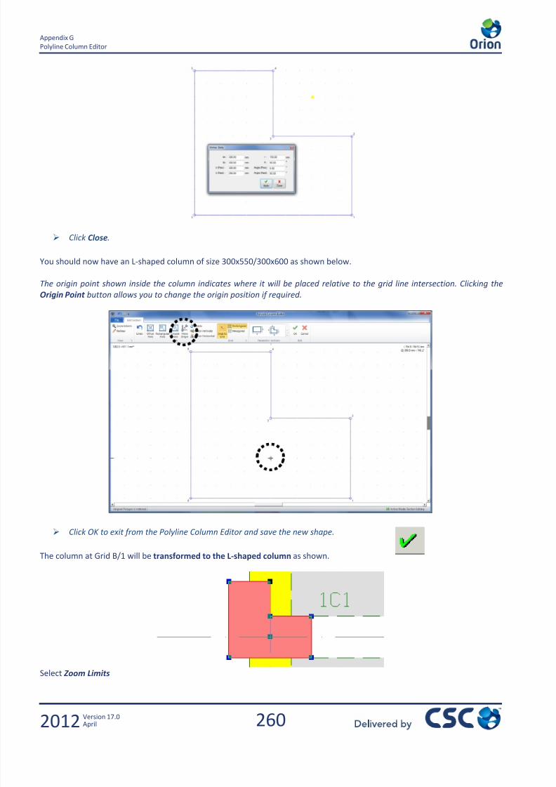
7/22/2019 Standard Training Manual
http://slidepdf.com/reader/full/standard-training-manual 261/286
260
Appendix G
Polyline Column Editor
2012 Version 17.0April
Click Close.
You should now have an L-shaped column of size 300x550/300x600 as shown below.
The origin point shown inside the column indicates where it will be placed relative to the grid line intersection. Clicking the
Origin Point button allows you to change the origin position if required.
Click OK to exit from the Polyline Column Editor and save the new shape.
The column at Grid B/1 will be transformed to the L-shaped column as shown.
Select Zoom Limits

7/22/2019 Standard Training Manual
http://slidepdf.com/reader/full/standard-training-manual 262/286
261
Appendix H
Polyline Column Editor
2012 Version 17.0April
18.0 Appendix H
Slab Design Using FE Analysis

7/22/2019 Standard Training Manual
http://slidepdf.com/reader/full/standard-training-manual 263/286
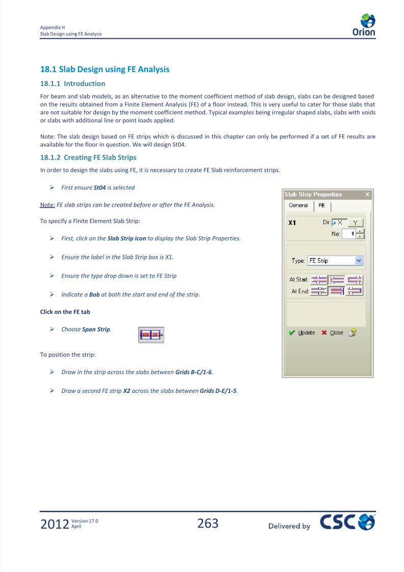
7/22/2019 Standard Training Manual
http://slidepdf.com/reader/full/standard-training-manual 264/286
263
Appendix H
Slab Design using FE Analysis
2012 Version 17.0April
18.1 Slab Design using FE Analysis
18.1.1 Introduction
For beam and slab models, as an alternative to the moment coefficient method of slab design, slabs can be designed basedon the results obtained from a Finite Element Analysis (FE) of a floor instead. This is very useful to cater for those slabs that
are not suitable for design by the moment coefficient method. Typical examples being irregular shaped slabs, slabs with voids
or slabs with additional line or point loads applied.
Note: The slab design based on FE strips which is discussed in this chapter can only be performed if a set of FE results are
available for the floor in question. We will design St04.
18.1.2 Creating FE Slab Strips
In order to design the slabs using FE, it is necessary to create FE Slab reinforcement strips.
First ensure St04 is selected
Note: FE slab strips can be created before or after the FE Analysis.
To specify a Finite Element Slab Strip:
First, click on the Slab Strip icon to display the Slab Strip Properties.
Ensure the label in the Slab Strip box is X1.
Ensure the type drop down is set to FE Strip
Indicate a Bob at both the start and end of the strip.
Click on the FE tab
Choose Span Strip.
To position the strip:
Draw in the strip across the slabs between Grids B-C/1-6.
Draw a second FE strip X2 across the slabs between Grids D-E/1-5.
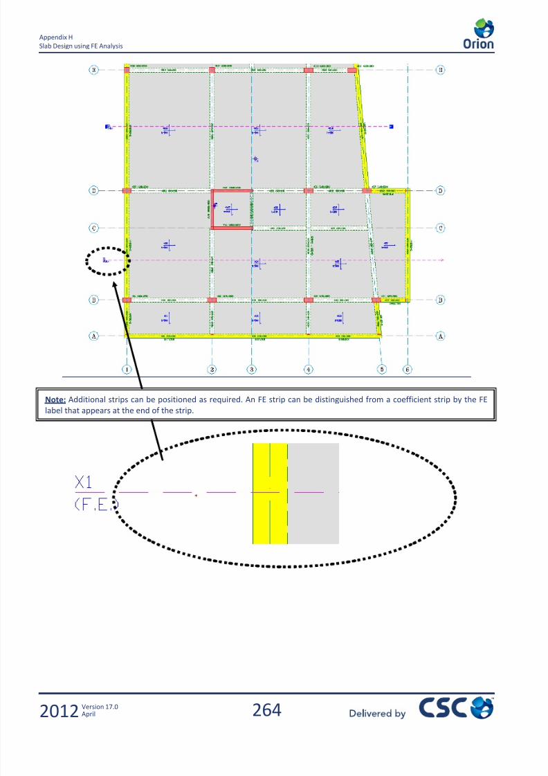
7/22/2019 Standard Training Manual
http://slidepdf.com/reader/full/standard-training-manual 265/286
264
Appendix H
Slab Design using FE Analysis
2012 Version 17.0April
Note: Additional strips can be positioned as required. An FE strip can be distinguished from a coefficient strip by the FElabel that appears at the end of the strip.

7/22/2019 Standard Training Manual
http://slidepdf.com/reader/full/standard-training-manual 266/286
265
Appendix H
Slab Design using FE Analysis
2012 Version 17.0April
18.1.3 Finite Element Model Generation
Ensure the Building Analysis results are up to date.
Select the FE Floor Analysis from the Run menu in the Main Menu bar.
Changing the Stiffness Factors may affect the results. More information on this is provided in the Engineer’s Handbook and
in Chapter 9 of this manual.
Select Storey ST04
Ensure the Stiffness Factors are all set to 0.33 and you have the below settings
Select Floor Mesh and Analysis
Select the Generate Mesh icon

7/22/2019 Standard Training Manual
http://slidepdf.com/reader/full/standard-training-manual 267/286
266
Appendix H
Slab Design using FE Analysis
2012 Version 17.0April
Now choose File/Exit to get back to the Finite Element Analysis Form dialog box.
18.1.4 FE Analysis Post Processing
Once the analysis is complete, click the Analysis Post-processing button
This takes you to the Post-Processor window with the model displayed as follows:
From the General Ribbon, click on the Plan View button as shown:
From the Results Ribbon, select the Standard Contour icon various effects can be displayed.

7/22/2019 Standard Training Manual
http://slidepdf.com/reader/full/standard-training-manual 268/286
267
Appendix H
Slab Design using FE Analysis
2012 Version 17.0April
Displacement contours. Moment Mx contours.
By manipulating the loading and effect drop-downs various other results can be viewed.
By selecting the Standard Contour icon once again the contours can be switched back off.
The results for the existing FE strips can be displayed using the Select Strip drop down.
Select the strip X2
The Moment diagram for strip X2 and the G+Q*F loading should appear as below.
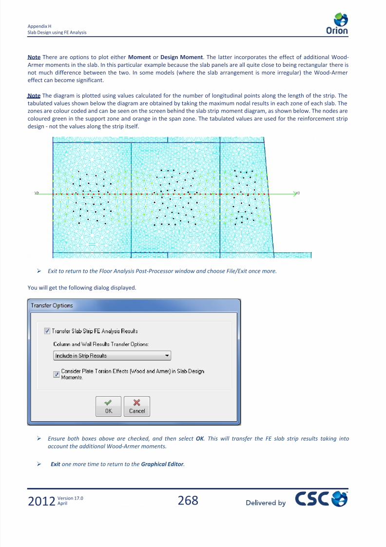
7/22/2019 Standard Training Manual
http://slidepdf.com/reader/full/standard-training-manual 269/286
268
Appendix H
Slab Design using FE Analysis
2012 Version 17.0April
Note There are options to plot either Moment or Design Moment. The latter incorporates the effect of additional Wood-
Armer moments in the slab. In this particular example because the slab panels are all quite close to being rectangular there is
not much difference between the two. In some models (where the slab arrangement is more irregular) the Wood-Armer
effect can become significant.
Note The diagram is plotted using values calculated for the number of longitudinal points along the length of the strip. The
tabulated values shown below the diagram are obtained by taking the maximum nodal results in each zone of each slab. The
zones are colour coded and can be seen on the screen behind the slab strip moment diagram, as shown below. The nodes are
coloured green in the support zone and orange in the span zone. The tabulated values are used for the reinforcement strip
design - not the values along the strip itself.
Exit to return to the Floor Analysis Post-Processor window and choose File/Exit once more.
You will get the following dialog displayed.
Ensure both boxes above are checked, and then select OK . This will transfer the FE slab strip results taking into
account the additional Wood-Armer moments.
Exit one more time to return to the Graphical Editor .
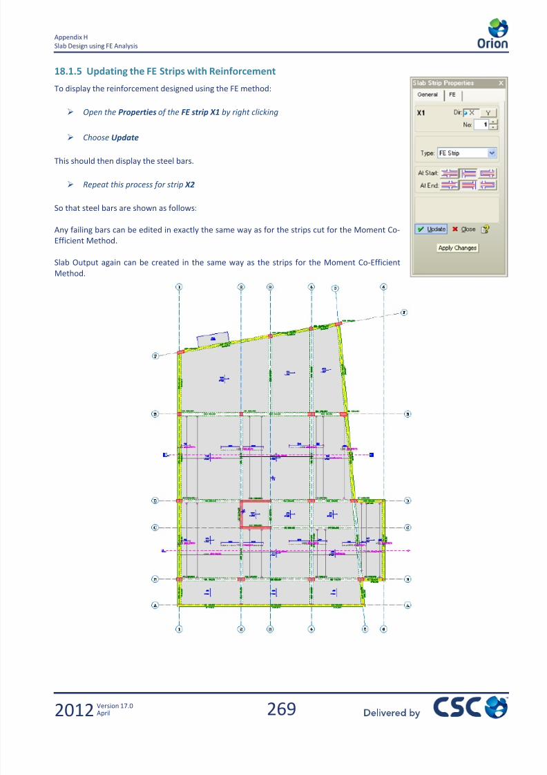
7/22/2019 Standard Training Manual
http://slidepdf.com/reader/full/standard-training-manual 270/286
269
Appendix H
Slab Design using FE Analysis
2012 Version 17.0April
18.1.5 Updating the FE Strips with Reinforcement
To display the reinforcement designed using the FE method:
Open the Properties of the FE strip X1 by right clicking
Choose Update
This should then display the steel bars.
Repeat this process for strip X2
So that steel bars are shown as follows:
Any failing bars can be edited in exactly the same way as for the strips cut for the Moment Co-
Efficient Method.
Slab Output again can be created in the same way as the strips for the Moment Co-EfficientMethod.

7/22/2019 Standard Training Manual
http://slidepdf.com/reader/full/standard-training-manual 271/286

7/22/2019 Standard Training Manual
http://slidepdf.com/reader/full/standard-training-manual 272/286
271
Appendix I
2012 Version 17.0April
19.0 Appendix I
Enhancing the GeneralArrangement Drawings

7/22/2019 Standard Training Manual
http://slidepdf.com/reader/full/standard-training-manual 273/286

7/22/2019 Standard Training Manual
http://slidepdf.com/reader/full/standard-training-manual 274/286
273
Appendix I
Enhancing the General Arrangement Drawings
2012 Version 17.0April
19.1 Enhancing the General Arrangement Drawings
19.1.1 Exercise Aims
Dimensioning the Grid Spacing
Dimensioning the Cantilever Slab
Creating Slab Cross-Sections
Exporting Drawings from Orion to AutoCAD
19.1.2 Dimensioning the Grid Spacing
The next task will be to add dimensions to the grids created.
Select the Dimensions icon or go to Member/Dimension.
So you should now have the Linear Dimension dialog box as shown below.
The top row of icons control the direction of the dimension
select Horizontal Dimension
The next row can be used to indicate if Continuous or Automatic dims are required and
also if the dim is to appear on the current storey only, or all storeys.
select Automatic Dimension
The third row is used to control the appearance of the extension lines.
Usually, dimensions are inserted with scale as "1". If two different drawing scales are
utilised on the same sheet (as in the column application drawings) the Dim Scale option
can be very useful to dimension entities drawn to the second scale.
Now we can dimension up the vertical grids. You will notice the status bar at the bottom of
the screen is prompting what to do next…
Click to the left of Grid 1 and drag to beyond Grid 6 and then release the left mouse button.
The status bar at the bottom of the screen then asks you to click on where you would like the dimension line to appear, as
shown below.
So click just above the protruding cantilever slabs.
Then the Automatic Dimension Parameters dialog box should appear.
Ensure that the Axes and Insert Total Dimension boxes are checked as shown below.
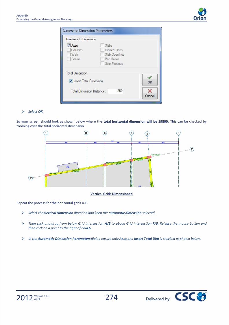
7/22/2019 Standard Training Manual
http://slidepdf.com/reader/full/standard-training-manual 275/286
274
Appendix I
Enhancing the General Arrangement Drawings
2012 Version 17.0April
Select OK .
So your screen should look as shown below where the total horizontal dimension will be 19800. This can be checked by
zooming over the total horizontal dimension
Vertical Grids Dimensioned
Repeat the process for the horizontal grids A-F.
Select the Vertical Dimension direction and keep the automatic dimension selected.
Then click and drag from below Grid intersection A/5 to above Grid intersection F/5. Release the mouse button and
then click on a point to the right of Grid 6.
In the Automatic Dimension Parameters dialog ensure only Axes and Insert Total Dim is checked as shown below.

7/22/2019 Standard Training Manual
http://slidepdf.com/reader/full/standard-training-manual 276/286
275
Appendix I
Enhancing the General Arrangement Drawings
2012 Version 17.0April
Then select OK
Your screen should look as shown below.
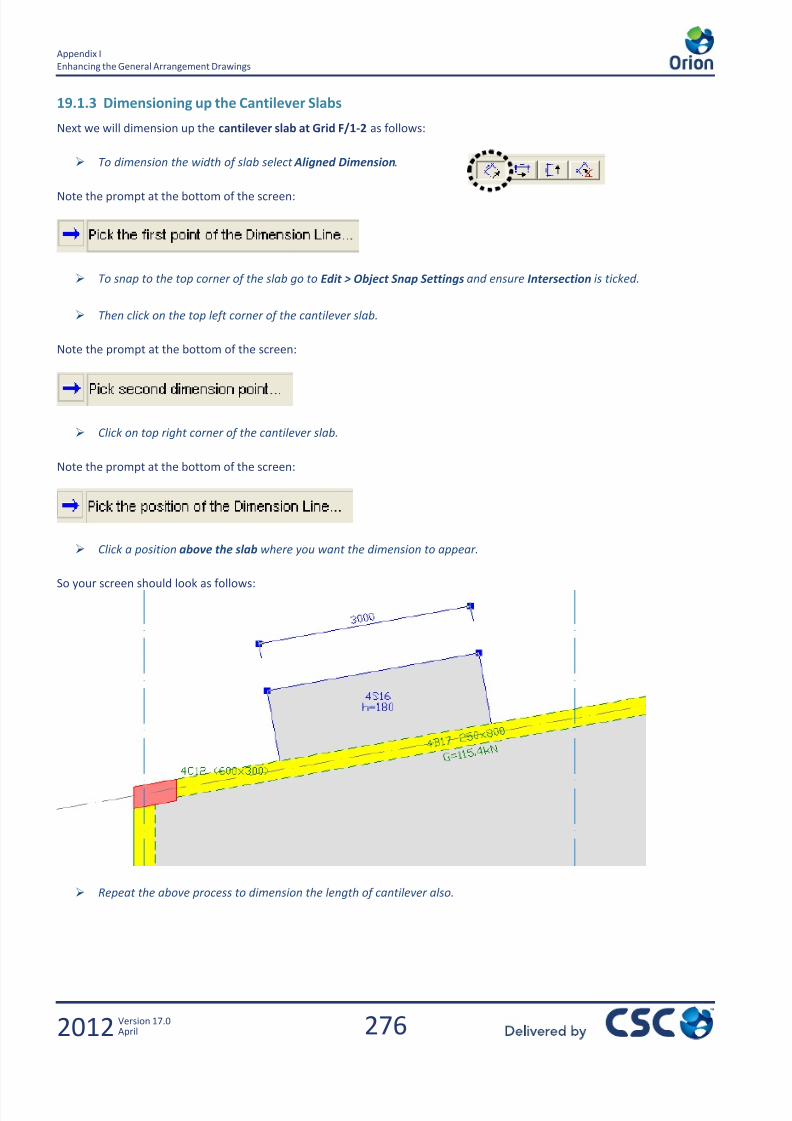
7/22/2019 Standard Training Manual
http://slidepdf.com/reader/full/standard-training-manual 277/286
276
Appendix I
Enhancing the General Arrangement Drawings
2012 Version 17.0April
19.1.3 Dimensioning up the Cantilever Slabs
Next we will dimension up the cantilever slab at Grid F/1-2 as follows:
To dimension the width of slab select Aligned Dimension.
Note the prompt at the bottom of the screen:
To snap to the top corner of the slab go to Edit > Object Snap Settings and ensure Intersection is ticked.
Then click on the top left corner of the cantilever slab.
Note the prompt at the bottom of the screen:
Click on top right corner of the cantilever slab.
Note the prompt at the bottom of the screen:
Click a position above the slab where you want the dimension to appear.
So your screen should look as follows:
Repeat the above process to dimension the length of cantilever also.
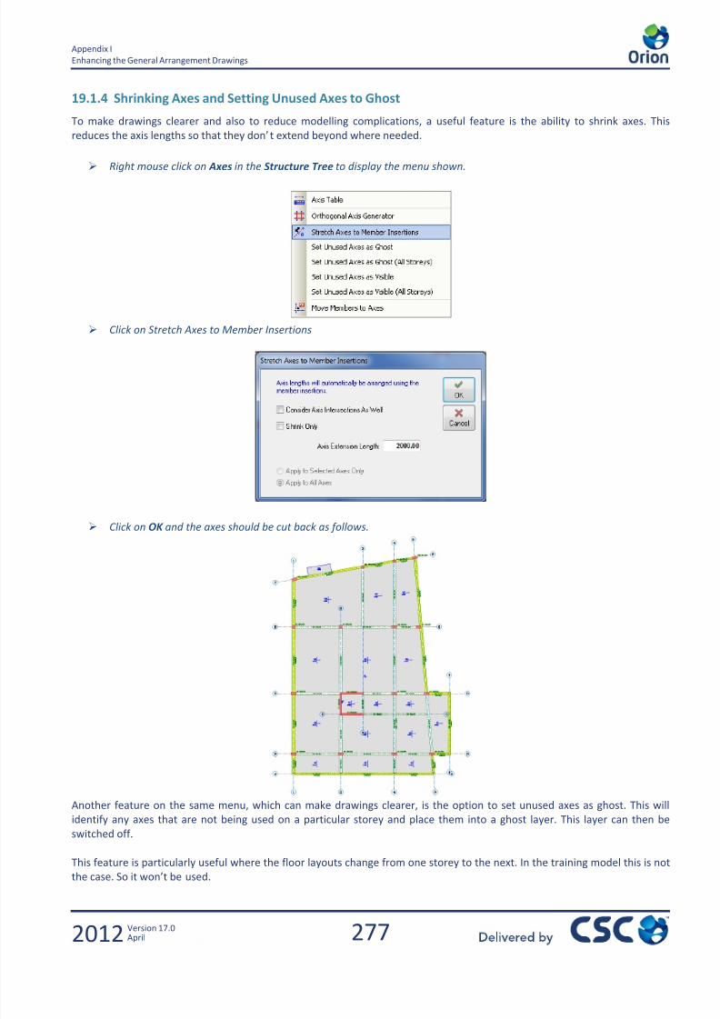
7/22/2019 Standard Training Manual
http://slidepdf.com/reader/full/standard-training-manual 278/286

7/22/2019 Standard Training Manual
http://slidepdf.com/reader/full/standard-training-manual 279/286
278
Appendix I
Enhancing the General Arrangement Drawings
2012 Version 17.0April
19.1.5 Creating Slab Section Views
Next we will create horizontal and vertical cross-sections through the 1st
storey.
Select the Section icon or go to Member > Section.
Then proceed as follows:
Position the cursor to the left of Grid 1 between Grid E-F above the slab opening
Press the CTRL key and click then drag the mouse so that it extends beyond Grid 5.
If necessary, select Zoom Limits then click above the top of the vertical grids to insert the Horizontal Cross-Section (A-
A)
Your screen should look as follows.
To get the reinforcement shown in the section, you must have designed the slabs with strips, then:
Tick the box Show Steel Bars then click on Update.

7/22/2019 Standard Training Manual
http://slidepdf.com/reader/full/standard-training-manual 280/286
279
Appendix I
Enhancing the General Arrangement Drawings
2012 Version 17.0April
Now draw a vertical section (Label it as B) between Grid 2-3/A-F.
Position the cursor below Grid A and between Grids 2 and 3, press the ‘CTRL’ button and then click and drag the
mouse so that it extends past Grid F.
You should now have 2 cross sections on your screen as shown below.
In Section B-B you can see the core walls. The amount that the walls (or columns) project above or below the section is
controlled using the Upper Col and Lower Col Len boxes.

7/22/2019 Standard Training Manual
http://slidepdf.com/reader/full/standard-training-manual 281/286

7/22/2019 Standard Training Manual
http://slidepdf.com/reader/full/standard-training-manual 282/286
281
Appendix J
2012 Version 17.0April
20.0 Appendix J
Orion Data File Structure andProject Settings

7/22/2019 Standard Training Manual
http://slidepdf.com/reader/full/standard-training-manual 283/286

7/22/2019 Standard Training Manual
http://slidepdf.com/reader/full/standard-training-manual 284/286
283
Appendix J
Orion Data File Structure and Project Settings
2012 Version 17.0April
20.1 Orion Data File Structure and Project Settings
Orion arranges the various files of a project automatically and stores them in folders with the same name as the given project
code.
Orion creates a folder for each project and saves all project files in this folder. In other words, all the files for a given project
will be located in the same folder. These folders will be named as the Project Code specified by the user for each project. You
are not permitted to include spaces in the Project Code.
Project folders are created under a parent folder called the "Orion Data Directory". There can be more than one data folder
for grouping the different projects. You can use spaces in the “Orion Data Directories" however the program will prevent
you from using them in the “Project Directory”.
You can change the current Orion Data Folder by the "Data Directory" button on the "Project Manager" form.
The Setup procedure creates a subfolder, "TMP", under the Orion Data Directory for the temporary files created during
project modelling analysis. "TMP" folder can be relocated or renamed but it shouldn't be removed. You can use the "Scratch
Directory" button on the "Project Manager" to relocate the temporary files' folder.
If you press the "OK" button to close the "Project Manager" the selected project will be loaded to the Graphical Editor and
the parameters will be saved in a file named as the <project code>.pbp.
For example, project parameters file created for the ABC1 project will be named as "ABC1.PBP" and will be stored in [Orion
Data Folder]\ABC1\ABC1.PBP" folder.

7/22/2019 Standard Training Manual
http://slidepdf.com/reader/full/standard-training-manual 285/286
284
Appendix J
Orion Data File Structure and Project Settings
2012 Version 17.0April
20.1.1 Project Settings
There are various project settings that can be modified to suit customer preference. Once set these will be saved with the
project.
New projects can be created either using the same project settings as a different project, or by using a Template of specific
settings.
An existing project will retain the project settings it had when it was last saved.
If you have an existing project with settings modified to your preference and you would like to apply those preferences to a
new project, simply select that existing project in the Settings Centre when creating the new project and Import the settings
you want. Alternatively, you could create a Template, also in the Settings Centre, which you could then apply to whichever
projects you like.
To revert to the default setting of the program, you can select one of the several default Templates available from the
Settings Centre.

7/22/2019 Standard Training Manual
http://slidepdf.com/reader/full/standard-training-manual 286/286