Embed Size (px)
Citation preview

STANDARD TESTING PROCEDURES (STP) FOR
EVALUATION OF REMOVAL EFFICIENCY OF COOKING FUME CONTROL EQUIPMENT
Environmental Protection Department
December 2004
(For Trial Use)

TABLE OF CONTENTS
Page
1. BACKGROUND 1 2. PURPOSE OF THE STP 1 3. STRUCTURE OF THE DOCUMENT 2 4. PRINCIPLE OF THE EVALUATON TEST 3 4.1 Scope and Application 4.2 Determination of Cooking Fume Removal Efficiency 5. APPARATUS AND CHEMICALS 5 5.1 The Setup of Testing Equipment 5.2 Sampling of Total Cooking Fume Particulates 5.3 Preparation of Calibration Standard for Infra-red (IR) Analysis 5.4 Sample Preparation and Analysis of Cooking Fume Samples 5.5 Specifications of Cooking Oil
6. STANDARD TESTING PROCEDURES TO EVALUATE THE COOKING FUME REMOVAL EFFICIENCY OF COOKING FUME CONTROL EQUIPMENT
11
6.1 Setting up of the Testing System 6.2 Generation of Cooking Fume 6.3 Pre-sampling Preparation Work 6.4 Collection of Cooking Fume Samples 6.5 Preparation of Calibration Standard 6.6 Preparation of Cooking Fume Quartz Filter Sample 6.7 Preparation of Probe Rinsing Sample 6.8 Preparation of IR Calibration Curve 6.9 Chemical Analysis of Sample 6.10 Data Treatment and Reporting 7. QUALITY ASSURANCE/QUALITY CONTROL 20 7.1 Qualification and Training of Technical Staff 7.2 Flow Rate Determination of the Testing System 7.3 Thermocouple 7.4 Isokinetic Sampling System 7.5 Analysis of Cooking Fume Sample 7.6 Quality Assurance and Quality Control of Measurement Results 8. SAFETY PRECAUTIONS 25 9. REFERENCES 27

Standard Testing Procedures on the Evaluation of the Operational Performance of Cooking Fume Control Equipment Environmental Protection Department
Page 1
1. BACKGROUND
Similar to other developed cities, Hong Kong is a small, densely populated city with large number of
restaurants located in urban area. The exhaust emissions from restaurants have been an environmental issue
in Hong Kong as oil mist of cooking fume cause nuisance to the general public and deteriorate the nearby
environment. In recent years, complaints about restaurant emissions have been quite substantial. The
HKSAR Government intends to control cooking fume emissions from restaurants and commercial kitchens
and encourage them to install appropriate types of control equipment.
There is a variety of cooking fume control equipment available in Hong Kong to reduce cooking fume
emissions, such as hydrovents, water scrubbers, air washers, grease filters, electrostatic precipitators, etc.
However, the cooking fume removal efficiency is variable among these types of equipment. It is difficult
for the users or the authority to assess whether the control equipment is effective in removing cooking fume.
Moreover, it will be even more difficult to compare the efficiency of two pieces of control equipment on
equal footing since there is no standard test for cooking fume.
Hong Kong Productivity Council was commissioned by the Environmental Protection Department in 2001 to
develop standard testing procedures (STP) to determine the cooking fume removal efficiency of typical
control equipment. After that, a couple of studies were undertaken with particular reference to the real-life
cooking process in a bid to refine the STP. The purpose of this revised STP is to lay down the details of the
equipment and testing procedures for determining the cooking fume removal efficiency of control equipment.
2. PURPOSE OF THE STP
The purpose of this STP is to provide standard testing procedures for suppliers and manufacturers of cooking
fume control equipment, testing laboratories and other concerned organizations to assess the performance of
cooking fume control equipment. This STP provides specific details on the sampling and analysis
procedures so that the removal efficiency of different cooking fume control equipment can be evaluated on
equal footing.
Testing laboratories or other testing organizations should follow this STP for certification with awareness of
quality assurance while carrying out the performance test for cooking fume control equipment.

Standard Testing Procedures on the Evaluation of the Operational Performance of Cooking Fume Control Equipment Environmental Protection Department
Page 2
3. STRUCTURE OF THE DOCUMENT
This STP provides information and testing procedures to evaluate the operational performance of cooking
fume control equipment. The structure of this document is summarized as follows:
Section 1 discusses the background and the objective of the document.
Section 2 states the purpose of the document
Section 3 illustrates the structure of the document
Section 4 of this document is to introduce the scope, application, principles and the referenced standard
testing methods for the performance evaluation
Section 5 details the apparatus and chemicals required for the performance test.
Section 6 details the standard testing procedures to determine the cooking fume removal efficiency of typical
cooking fume control equipment with a laboratory scale setup.
Section 7 discusses the quality assurance and quality control (QA/QC) for the evaluation of cooking fume
removal efficiency. The QA/QC is essential to ensure the quality and reliability of test results.
Section 8 illustrates the safety precautions when carrying out performance test. The performance test
involves generation of cooking fume using cooking woks over LPG / Town Gas fired stoves which may
cause burns and fire hazards.
Section 9 contains a list of relevant reference documents.

Standard Testing Procedures on the Evaluation of the Operational Performance of Cooking Fume Control Equipment Environmental Protection Department
Page 3
4 PRINCIPLE OF THE EVALUATION TEST
4.1 Scope and Application
This STP intends to provide the techniques for determination of overall removal performance of control
equipment using a continuous stream of oily fumes generated under specified conditions. The testing
procedures should be followed to measure the collection efficiency of equipment by comparing the
concentration of oil particles in the upstream to that in the downstream.
The test equipment may include electrostatic precipitators (EP) – duct-type EP and hood-type EP,
hydrovent, grease filter, water scrubber, air washer, etc. The testing procedures can also be applied to
assessing overall removal efficiency of control equipment which are aligned in series along the exhaust
duct.
This method is applicable to cooking fumes flowing in exhaust ducts or stacks. The setup outlined in
this STP is intended for a typical system with flow rate of 4000 m3/hr which is normally used in a small
scale commercial kitchen with 2 stoves. For control equipment exceeding this handling capacity,
scaling up the appropriate design features such as ducting, exhaust blower and fume generating unit would be needed but the inlet fume concentration at control equipment must be made to 100 ± 20
mg/m3 (expressed at 0°C and 101.325 kPa) and the flow rate of exhaust stream must tally with the rated flow rate of the control equipment for optimal collection of oil particles.
4.2 Determination of Cooking Fume Removal Efficiency
The primary function of cooking fume control equipment is to eliminate or reduce the level of cooking
fume in restaurant exhausts which cause nuisance to the nearby environment. Cooking fume control
equipment, such as electrostatic precipitators, water scrubbers, air washers, hydrovents or grease filters
should have certain cooking fume removal efficiency. The aim of the standard testing procedures is to
determine the efficiency of a cooking fume control equipment to remove total cooking fume from the
kitchen exhaust. The principle of the evaluation of the cooking fume removal efficiency as detailed in
the Section 6 is summarized as follows:
a. Setting up of a standard testing system including a cooking fume generation system, an inlet and
outlet exhaust ductings which comply with the standard isokinetic stack sampling requirements, a
variable exhaust gas flow rate controlling device and the cooking fume control equipment under
test;
b. Generation of a constant and persistent level of cooking fume which is similar to the cooking
fume emission from local restaurants iii;

Standard Testing Procedures on the Evaluation of the Operational Performance of Cooking Fume Control Equipment Environmental Protection Department
Page 4
c. Measurement of the levels of total cooking fume at both the inlet and outlet ductings at the same
time in accordance with USEPA Method 5 “Determination of Particulate Matters Emissions from
Stationary Sources” i;
d. Conducting the efficiency test at the 100% of the design flow rate of the cooking fume control
equipment under test;
e. Analysis of the level of cooking fume in the samples by infra-red spectroscopy in accordance
with the PRC National Emission Standard GB-18483-2001 ii;

Standard Testing Procedures on the Evaluation of the Operational Performance of Cooking Fume Control Equipment Environmental Protection Department
Page 5
The standard test methods referenced for the evaluation of cooking fume control equipment in the STP
is based on the Report on Literature Survey of Legislative Control and Testing Method of Cooking
Fume Control Equipment for Cooking Fume Control.iv issued on 11 February 2002 and, Report on
Evaluation of Cooking Fume Emission Characteristicsviii (27 February 2004).
It was known that rapeseed oil is usually used in restaurants and food stores for cooking; therefore
rapeseed oil shall be used as the sources of cooking fume for the performance test. Rapeseed oil with
characteristics similar to those described in para. 5.5 should be used.
5 APPARATUS AND CHEMICALS
The section details the list of equipment, apparatus, chemicals and other accessories which is required to
carry out the tasks of determination of total cooking fume removal efficiency of a wide range of cooking
fume control equipment.
5.1 The Setup of Testing Equipment
A laboratory scale testing setup shall be prepared to carry out the evaluation. The setup shall consist
of a cooking fume generation system to simulate cooking process and generate sufficient cooking fume
for the evaluation, an inlet and outlet ductings connected to the equipment under test without air
leakage.
In addition, the setup shall also include a flow rate control damper and an exhaust fan (or the built-in
fan of the testing equipment) to facilitate the measurements of the desired flow rate. The drawings of
the testing system are shown as Figure 5.1.
Design Specifications of the testing setup
The design specifications of the experimental setup are summarized in Table 5.1

Standard Testing Procedures on the Evaluation of the Operational Performance of Cooking Fume Control Equipment Environmental Protection Department
Page 6
Table 5.1 Design Specifications of the Testing Setup for Determination of Total Particulate Removal Efficiency
Item Symbol
In DrawingSpecifications
Cooking fume generating chamber A The cooking fume generation chamber shall be in the form of a range of two cooking stoves under an overhead exhaust hood as shown in Figure 5.1. Apparatus i. Two LPG/Town Gas fired stoves; ii. Two cooking woks of size 42 cm diameter each
providing oil bath capacity of 3 litres; iii. Rapeseed cooking oil; iv. Stirring rods (or ladle) or any mechanical stirrer ; v. J-type thermocouple ((0-500°C) fixed at stand; vi. Protective shields; vii. Fire extinguishers (CO2/dry powder type).
Inlet ducting B The dimensions of the inlet ducting shall follow the requirements of USEPA Method 1 viii. The length of the inlet ducting shall be more than 10 times of effective diameter of the ducting. If the ducting is rectangular shape, the effective (hydraulic) diameter is calculated as 2LxW/(L+W) where L is length and W is width. (See Figure 5.1)
Outlet ducting C The dimensions of the outlet ducting shall follow the requirements of USEPA Method 1. The length of the outlet ducting shall be more than 10 effective diameters of the ducting. The ducting shall be made of galvanized iron sheet.
Flow control damper D The flow control damper shall be able to control the flow rate of the test system (Flow control damper is not necessary if the flow rate of the exhaust air fan is adjustable).
Exhaust fan E The exhaust fan shall be capable of maintaining the flow rate at 125% of the design flow rate of the test control equipment.
Inlet sampling holes F The inlet sampling holes shall be located at least 8 effective diameters of the ducting from the inlet of the ducting and 2 effective diameters away from the outlet. Three 100 mm sampling holes should be prepared corresponding to the level of the three rows in fig. 6.2
Outlet sampling holes G The outlet sampling holes shall be assigned at least 8 effective diameters of the ducting from the inlet of the ducting and 2 effective diameters away from the flow control damper. Three 100 mm sampling holes should be prepared corresponding to the level of the three rows in fig. 6.2.

Standard Testing Procedures on the Evaluation of the Operational Performance of Cooking Fume Control Equipment Environmental Protection Department
Page 7
Exhaust
Outlet
De = Effective / Hydraulic diameter = 4A/P = 2(L*W)/(L+W)
where A refers to area; P to perimeter; L to length; W to width.
Control
Equipment
Figure 5.1 Schematic View of the Testing System
C AB
F G D
E
Duct - 400 x 400 mm Duct - 400 x 400 mm
2 De 8 De 8 De 2 De
LPG / Town gas Adaptors
Woks with
rapeseed oil 0.8m
1.5m
2.2m

Standard Testing Procedures on the Evaluation of the Operational Performance of Cooking Fume Control Equipment Environmental Protection Department
Page 8
Fig 5.2 Arrangement of Sampling probe into the duct

Standard Testing Procedures on the Evaluation of the Operational Performance of Cooking Fume Control Equipment Environmental Protection Department
Page 9
5.2 Sampling of Total Cooking Fume Particulates
The sampling of total cooking fume particulates at inlet and outlet streams of the test equipment shall
be carried out simultaneously and in accordance with USEPA method 5. The setup of the sampling
system is shown in Figures 5.1 and 5.2. The sample collection system shall include the following
items:
5.2.1 Standard isokinetic Total particulate sampling system is equipped with
- Total Particulate sampling nozzle
- S-type pitot tube
- Heated glass sampling probe, filter holder and impingers;
- Universal stack sampling system with stack sampling panel, equipped with control console,
water manometer, dry gas meter, etc.
5.2.2 0 - 360°C thermometer; 5.2.3 Barometer;
5.2.4 Quartz filter
5.2.5 Distilled water and ice;
5.2.6 Anhydrous silica gel;
5.2.7 Perchloroethylene, Analytical Reagent grade or above;
5.2.8 Wash bottle;
5.2.9 Petri dish and clean glass sampling bottles
5.2.10 Forceps and clean gloves
5.2.11 Stopcork grease (if ball-joint type sampling glassware is used, stopcork silicon grease shall be
applied to ball joints to avoid air leak)
5.3 Preparation of Calibration Standard for Infra-red Analysis
5.3.1 High quality rapeseed cooking oil;
5.3.2 Perchloroethylene, (Analytical Reagent grade)
5.3.3 Round bottom flask and water condenser for reflux of cooking oil
5.3.4 Heater or heating mantle
5.3.5 Mercury in glass thermometer of range 0 - 360°C 5.3.6 Boiling stone
5.3.7 Clean glass sampling bottle
5.3.8 0 – 5 ml glass syringe
5.3.9 Electronic balance
5.3.10 50 ml volumetric flask

Standard Testing Procedures on the Evaluation of the Operational Performance of Cooking Fume Control Equipment Environmental Protection Department
Page 10
5.3.11 15 ml glass vials with teflon lined cap
5.4 Sample Preparation and Analysis of Cooking Fume Samples
5.4.1 Perchloroethylene, (Analytical Reagent grade)
5.4.2 Conical flask
5.4.3 Separating funnel
5.4.4 25 ml and 50 ml Volumetric flasks
5.4.5 0 – 10 ml measuring cylinder
5.4.6 15 ml glass vials with teflon lined cap
5.4.7 Wash bottle and dropper
5.4.8 Ultrasonic bath for laboratory use
5.4.9 FT-IR or IR spectrometer
5.4.10 Liquid cell for IR spectrometer
5.4.11 Tissue paper
5.4.12 Waste solvent container
5.4.13 Laboratory gloves
5.5 Specifications of Cooking Oil
The cooking oil used for testing should be the kind of rapeseed oil with the following general
specifications:
Acid value ≤0.2; Peroxide value ≤5; Colour Y ≤20, R ≤2.0; Refractive Index 1.465-1.467; Smoke point ≥230oC; Fatty acid composition C16:0 2.5-7.0%, C18:0 0.8-3.0%, C18:1 51-70%, C18:2 15-30%, C18:3 5-15%,
C20:0 0.2-1.2%, C20:1 0.1-4.3%, C22:0 < 0.6% C22:1 <2%, C24:0 <3% C24:1 <0.4%

Standard Testing Procedures on the Evaluation of the Operational Performance of Cooking Fume Control Equipment Environmental Protection Department
Page 11
6 STANDARD TESTING PROCEDURES TO EVALUATE THE COOKING FUME REMOVAL
EFFICIENCY OF COOKING FUME CONTROL EQUIPMENT
6.1 Setting up of the Testing System
6.1.1 Setup the testing system as per schematic diagrams Figures 5.1 & 5.2. Ensure all the
connections and interfaces with the control equipment under test are air-leak free.
6.1.2 Connect electric supply to the testing system. Verify all the components are working properly.
Check whether the flow rate of the testing system is adjustable.
6.1.3 Check the operation of the cooking fume control equipment under test. Connect water supply
whenever necessary.
6.1.4 Setup the Total Particulate sampling system1. Connect the sampling probe with the sampling
panel. Check all the components of the sampling system are in proper operation.
6.1.5 Check the flow rate of testing system with the sampling system whether it can attain 100%
design flow rate of the testing equipment.
6.1.6 Check whether all the safety measures are in order. (Refer to Section 8 for details of safety
measures of the test).
6.2 Generation of Cooking Fume
6.2.1 Setup the cooking fume generation chamber with fabrication of the LPG / Town Gas fired
stoves, cooking woks, rapeseed cooking oil and stirring mechanism.
6.2.2 Each cooking wok should be of size 42 cm (approx. 17 inches) diameter to accommodate an
oil bath quantity of 3 litres.
6.2.3 Use commercially available rapeseed oil (see Para. 5.5 for specifications) for generation of
fumes for the test. Maintain oil bath temperature at 300 + 10o C (can be continuously
monitored by thermocouples). Replenish oil regularly to make up for the loss.
6.2.4 The acceptable range of the concentration of total cooking fume in the inlet stream shall be
maintained at 100 + 20 mg/m3 (expressed at 0°C and 101.325 kPa). The oily fumes should be generated by constant stirring of oil in woks over stoves (at frequency 20-30 strokes per
minute).
6.2.5 To achieve such a high fume concentration, two identical woks must be used at the same time.
6.2.6 The volume flowrate will be similar to the real life situation, i.e. 4000 m3/hr for 2 woks and the
cross-sectional area of the exhaust duct where the control equipment to be tested must be
around 400 mm x 400 mm as the flow velocity has to be set for 7 m/s in line with the real-life
situation.
1 The sampling procedure for total cooking fume efficiency test shall follow the relevant requirements as set out in US EPA
Method 5 on Determination of Particulate Matter Emissions from Stationary Sources.

Standard Testing Procedures on the Evaluation of the Operational Performance of Cooking Fume Control Equipment Environmental Protection Department
Page 12
6.2.7 The above setup is designed for a typical system with flow rate of 4000 m3/hr which is being
used in a small scale restaurant with 2 stoves. If the control equipment to be tested exceeds
this capacity requirement, scaling up the appropriate design features such as ducting and fume
generating unit will be needed in order to ensure the inlet fume concentration at control
equipment be maintained at 100 + 20 mg/m3.
6.2.8 Should any set of test data after IR analysis reveal the inlet fume concentration falling beyond 100 ± 20 mg/m3, the results for the removal efficiency should be made void and it is required to
redo the sampling for an acceptable set of test data.

Standard Testing Procedures on the Evaluation of the Operational Performance of Cooking Fume Control Equipment Environmental Protection Department
Page 13
6.3 Pre-sampling Preparation Work
6.3.1 Switch on the cooking fume generation system and the cooking fume control equipment and
warm up the systems for at least 15 minutes;
6.3.2 Adopt USEPA Method 5 “Determination of Particulate Matter Emissions from Stationary
Sources” for isokinetic sampling and PRC National Standard “Emission Standards of Cooking
Fume, GB 18483-2001” for determining the mass concentrations of the collected samples
before and after the control equipment under testing;
6.3.3 Check the flow rate of the testing system whether the flow rate is 100% of the design flow rate
of the equipment under test;
6.3.4 Clean the sampling components with perchloroethylene thoroughly to remove any contaminant,
air dry the clean sampling inlets;
6.3.5 Setup the two total particulate sampling systems in accordance with the USEPA Method 5 for
the inlet and outlet streams respectively. Figure 6.1 shows the sampling setup;
6.3.6 Check the integrity of the particulate filter, there shall be no other contaminant and pin hole on
the filter. Place the particulate filter at the filter house with gloved hands and a pair of forceps;
6.3.7 Conduct a leak check on each sampling train. Seal the sampling inlet with a teflon tape and
pressed with the thumb. Switch on the sampling pump to create a vacuum environment to
about –20 psi. Switch off the sampling pump and note the pressure change. If the pressure
increases steadily, that is a sign of air leak. Check all the fittings to rectify the problem.
Otherwise if the vacuum pressure is maintained, the sampling system is considered as leak free
and can be used for sampling.
6.3.8 Two units of isokinetic sampling system as stated in Para. 6.3.5 above are set one at the inlet
and another one at the outlet ducting to collect cooking fume simultaneously.

Standard Testing Procedures on the Evaluation of the Operational Performance of Cooking Fume Control Equipment Environmental Protection Department
Page 14
Figure 6.1Drawing of the Stack Sampling System adopted from USEPA method 5 (Figure adopted from USEPA Method 5, 40 CRF 60 Appendix A)

Standard Testing Procedures on the Evaluation of the Operational Performance of Cooking Fume Control Equipment Environmental Protection Department
Page 15
6.4 Collection of Cooking Fume Samples
6.4.1 Start the sampling at inlet and outlet at the same time. During the sampling run, maintain an
isokinetic sampling rate (within 10 percent of true isokineticity);
6.4.2 When inserting the sampling inlet, make sure the sampling inlet is parallel to the air ducting
and pointing upstream;
6.4.3 Collect cooking fume sample according to the sampling traverse plan shown in Fig 6.2
(USEPA Method 1)vii. The total sampling time for each sample is around 30 minutes, so the
sampling time at each of the “X” locations shown below is around 3 minutes.
6.4.4 For each test, record the data required on a data sheet.
6.4.5 Record the actual sampling time for each sample. It should be around 30 minutes. During
sampling, monitor the flow rate of the system in order to adjust the sampling flow rate to
maintain the isokineticity.
6.4.6 Determine the overall isokineticity. If the isokineticity is beyond the range of 90% to 110%,
void the sample. If the isokineticity pass the criterion, calculate the total sample volume
corrected to 0°C and 101.325 kPa using the temperature measured by thermocouples secured to the sampling probe inlet.
6.4.7 After sampling, conduct a post leak check similar to step 6.3.7. If the post leak check fails,
void the sample.
6.4.8 Collect the particulate filter with gloved hand and a pair of forceps. Put the filter on a petri
dish which shall then be properly labelled.
6.4.9 Rinse the internal surface of the sampling probe up to the filter holder with perchloroethylene
to remove any oil particulates deposited on such surface.
6.4.10 Record the sample identity of the “Filter” and “Rinsing” respectively.
6.4.11 Repeat the procedures of 6.4.1 to 6.4.10 for 4 more times to get a total of 5 sets of sample.
X X X
X X X
X X X
Figure 6.2 Transverse plan of the ducting showing the sampling locations

Standard Testing Procedures on the Evaluation of the Operational Performance of Cooking Fume Control Equipment Environmental Protection Department
Page 16
6.5 Preparation of Calibration Standard
6.5.1 Use commercially available rapeseed oil as the calibration standard;
6.5.2 Reflux rapeseed oil at 220°C for 2 hours using a 25 ml round bottom flask and a water condenser;
6.5.3 Cool down the 25 ml round bottom flask to room temperature;
6.5.4 Put a dried 50 ml volumetric flask, prewashed with perchloroethylene,1 onto an electronic
balance, and tare the balance to zero;
6.5.5 Transfer about 170 mg of the refluxed rapeseed oil to the volumetric flask and record the actual
weigh of rapeseed oil to 0.1 mg;
6.5.6 Dilute the 50 ml volumetric flask to the mark.with perchloroethylene; cap the flasks and shake
vigorously;
6.5.7 Pipette 0.2, 0.3, 0.5, 1.0, 3.0 and 5.0 ml of the solution, prepared in Para. 6.5.6 above, into six
separate dried and cleaned 50 ml volumetric flasks;
6.5.8 Top up the volumetric flasks to the marks with perchloroethylene, cap the flasks and shake
vigorously;
6.5.9 The calibration standards represent 0.014, 0.020, 0.034, 0.068, 0.205 and 0.341 mg/ml cooking
fume in solvent. (May be different for different batches of cooking oil used, but must use the
same one for IR analysis)
1 Analytical Reagent grade
Standard Testing Procedures on the Evaluation of the Operational Performance of Cooking Fume Control Equipment Environmental Protection Department
Page 17
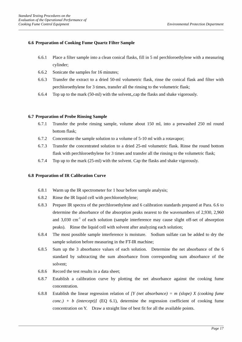
6.6 Preparation of Cooking Fume Quartz Filter Sample
6.6.1 Place a filter sample into a clean conical flasks, fill in 5 ml perchloroethylene with a measuring
cylinder;
6.6.2 Sonicate the samples for 16 minutes;
6.6.3 Transfer the extract to a dried 50-ml volumetric flask, rinse the conical flask and filter with
perchloroethylene for 3 times, transfer all the rinsing to the volumetric flask;
6.6.4 Top up to the mark (50-ml) with the solvent,,cap the flasks and shake vigorously.
6.7 Preparation of Probe Rinsing Sample 6.7.1 Transfer the probe rinsing sample, volume about 150 ml, into a prewashed 250 ml round
bottom flask;
6.7.2 Concentrate the sample solution to a volume of 5-10 ml with a rotavapor;
6.7.3 Transfer the concentrated solution to a dried 25-ml volumetric flask. Rinse the round bottom
flask with perchloroethylene for 3 times and transfer all the rinsing to the volumetric flask;
6.7.4 Top up to the mark (25-ml) with the solvent. Cap the flasks and shake vigorously.
6.8 Preparation of IR Calibration Curve
6.8.1 Warm up the IR spectrometer for 1 hour before sample analysis;
6.8.2 Rinse the IR liquid cell with perchloroethylene;
6.8.3 Prepare IR spectra of the perchloroethylene and 6 calibration standards prepared at Para. 6.6 to
determine the absorbance of the absorption peaks nearest to the wavenumbers of 2,930, 2,960
and 3,030 cm-1 of each solution (sample interference may cause slight off-set of absorption
peaks). Rinse the liquid cell with solvent after analyzing each solution;
6.8.4 The most possible sample interference is moisture. Sodium sulfate can be added to dry the
sample solution before measuring in the FT-IR machine;
6.8.5 Sum up the 3 absorbance values of each solution. Determine the net absorbance of the 6
standard by subtracting the sum absorbance from corresponding sum absorbance of the
solvent;
6.8.6 Record the test results in a data sheet;
6.8.7 Establish a calibration curve by plotting the net absorbance against the cooking fume
concentration.
6.8.8 Establish the linear regression relation of [Y (net absorbance) = m (slope) X (cooking fume
conc.) + b (intercept)] (EQ 6.1), determine the regression coefficient of cooking fume
concentration on Y. Draw a straight line of best fit for all the available points.

Standard Testing Procedures on the Evaluation of the Operational Performance of Cooking Fume Control Equipment Environmental Protection Department
Page 18
(For illustration ONLY)
Area of Peak
y = 2165.1x + 51.835
R2 = 0.9985
0
100
200
300
400
500
600
700
800
900
0 0.05 0.1 0.15 0.2 0.25 0.3 0.35 0.4
Concentration (mg/mL)
6.9 Chemical Analysis of Sample
6.9.1 Rinse the liquid cell with perchloroethylene before analyzing each sample;
6.9.2 Rinse the liquid cell with small amount of sample extract;
6.9.3 Transfer the sample extract from the vial to the liquid cell Clean the surface of the cell with
tissue paper;
6.9.4 Prepare an IR spectrum of the sample as the step 6.8.3. Determine the net absorbance of the
sample by subtracting the sum of absorbance of 2930, 2960 and 3030 cm-1 of the sample from
the absorbance value of the solvent;
6.9.5 Record the test results in a data sheet;
6.9.6 Repeat the steps 6.9.1 through 6.9.5 to analyze other samples;
6.9.7 Determine the concentration of cooking fume by comparing with the calibration curve.
Figure 6.3 IR Calibration Curve for Analysis of Cooking Fume

Standard Testing Procedures on the Evaluation of the Operational Performance of Cooking Fume Control Equipment Environmental Protection Department
Page 19
6.10 Data Treatment and Reporting
6.10.1 Determine the concentration of cooking fume in air sample at 0°C and 101.325 kPa in mg/m3 by the equation EQ 6.2
(Conc. of cooking fume in extract, mg/ml) x marked
volume of flask used Conc. of cooking = fume in air sample (total air sample volume at 0°C and 101.325 kPa, m3)
.... EQ 6.2
6.10.2 Compare the pair of cooking fume concentrations in both inlet stream and outlet stream air,
calculate the removal efficiency by the equation EQ 6.3
(Conc of cooking fume in outlet stream) Cooking fume
removal efficiency
= (1 - (Conc of cooking fume in inlet stream)
) x 100% .... EQ 6.3
6.10.3 Calculate the cooking fume removal efficiencies of the 5 sets of valid samples obtained in
Section 6.4 under the same system flow rate. (check also the criteria in para. 7.6.4 are met)
6.10.4 Calculate the average removal efficiency with the valid samples;

Standard Testing Procedures on the Evaluation of the Operational Performance of Cooking Fume Control Equipment Environmental Protection Department
Page 20
7 QUALITY ASSURANCE/QUALITY CONTROL
Following are major considerations that can be taken to help ensure reliable and quality test runs:
7.1 Qualification And Training Of Technical Staff
7.1.1 Technical staff to operate the cooking fume removal efficiency test system and collection of
cooking fume samples shall possess a diploma or above in science or engineering discipline;
7.1.2 Laboratory staff to prepare and analyze cooking fume samples shall possess a diploma or
above in chemistry;
7.1.3 Technical staff to operate the testing system and collect cooking fume samples shall receive
training in the requirement of the STP, operation of the testing system, isokinetic stack
sampling, operation of stack sampling system and QA/QC. Training may be conducted in
classroom lectures with illustration and/or on-site demonstration. Appropriate assessment
shall be conducted to assess the capability of the trainees. Only competent persons who pass
the respective assessment are allowed to conduct the cooking fume sampling work.
7.1.4 Laboratory staff to prepare and analyze cooking fume samples shall receive training in the
preparation of sample, operation of the respective IR spectrometer, data interpretation and
QA/QC. Training may be conducted in classroom lecture and/or on-site demonstration.
Appropriate assessment shall be conducted to assess the capability of the trainees. Only
competent persons who pass the respective assessment are allowed to conduct the cooking
fume analytical work.
7.1.5 Training and assessment record for each staff shall be maintained and filed.
7.2 Flow Rate Determination of the Testing System
7.2.1 A standard pitot tube shall be used to measure the flow rate of the testing system. The flow
measuring equipment shall be calibrated by the manufacturer or other qualified agents. A
valid calibration certificate shall be obtained after calibration.
7.2.2 The condition and performance of the flow measuring equipment shall be checked prior to
each measurement to ensure proper operation.

Standard Testing Procedures on the Evaluation of the Operational Performance of Cooking Fume Control Equipment Environmental Protection Department
Page 21
7.3 Thermocouple
7.3.1 The thermocouple used for temperature measurement shall possess a valid calibration
certificate, otherwise calibration against a certified mercury-in-glass thermometer shall be
conducted. The linear regression relation of the actual temperature against measured
temperature between the temperature range 0 - 500°C shall be established with at least 5 calibration points.

Standard Testing Procedures on the Evaluation of the Operational Performance of Cooking Fume Control Equipment Environmental Protection Department
Page 22
7.4 Isokinetic Sampling System
7.4.1 Isokinetic sampling system shall be calibrated according to the requirements of “Quality
Assurance Handbook for Air Pollution Measurement System, Vol. III, Stationary Sources
Specific Methods”, USEPAvi.
7.4.2 To collect a representative sample of cooking fumes from an exhaust duct, insert a probe
coupled to a filter holder. Achievement of accurate isokinetic sampling demands that the gas
linear velocity at the probe opening match that in the duct. Failure to match the probe and
duct velocities will cause a distortion of testing data resulted from drawing in either larger
particles (probe velocity lower than duct velocity) or smaller particles (probe velocity higher
than duct).
7.5 Analysis of Cooking Fume Sample
7.5.1 All volumetric glassware shall be calibrated by gravimetric method;
7.5.2 Electronic balance shall be calibrated against standard weights;
7.5.3 IR spectrometer shall be maintained properly in accordance with the requirements of the
service manual.
7.6 Quality Assurance and Quality Control of Measurement Results
7.6.1 Determination of Method Detection Limit
7.6.1.1 Calibrate the IR spectrometer according to the steps 6.8;
7.6.1.2 Prepare a standard rapeseed oil mixture in perchloroethylene with concentration of about
10% of the calibration range;
7.6.1.3 Analyze the concentration of the rapeseed oil standard according to the steps 6.9 for 7
times, calculate the average and the standard deviation of the concentration;
7.6.1.4 Determine the detection limit of the IR-spectrometer according to the equation EQ-8.1
Detection limit (DL) = 3.14 x standard deviation .... EQ-8.1
7.6.1.5 Determine the average total sample volume of 80% design flow rate (0°C and 101.325 kPa). Determine the method detection limit (MDL) according to the detection limit
of the IR-spectrometer according to the equation EQ-8.2
(DL of the IR spectrometer, mg/ml) x 25 ml MDL = (average air sample volume of 80% flow rate, m3)
.... EQ –8.2

Standard Testing Procedures on the Evaluation of the Operational Performance of Cooking Fume Control Equipment Environmental Protection Department
Page 23
7.6.2 Recovery of Standard Rapeseed Oil Samples
The test of rapeseed oil recovery is to evaluate whether the IR-spectrometer reports accurate
cooking fume concentration in perchloroethylene extract.
7.6.2.1 Calibrate the IR spectrometer according to the steps 6.8;
7.6.2.2 Prepare 3 standard rapeseed oil mixtures in perchloroethylene with concentrations of
about 30%, 50% and 80% of the calibration range;
7.6.2.3 Analyze the concentration of the rapeseed oil mixtures according to the steps 6.9,
compare the measured concentration and the standard concentration and calculate the
percentage recover according to the equation EQ-8.3
(measured concentration) x 100% % recovery = (standard concentration of rapeseed mixture)
.... EQ –8.3
7.6.3 Recovery of Spiked Filter
The test of recovery of spiked filter is to evaluate the recovery of cooking fume from sampled
particulate filters through the ultrasonic extraction process.
7.6.3.1 Weigh about 2 mg of rapeseed oil with a glass syringe and electronic balance, record the
actual weight of rapeseed oil;
7.6.3.2 Spike the weighed oil to a clean particulate filter, then air dry the filter;
7.6.3.3 The range of relative humidity for preparing the clean filter paper and for air drying the
filter should be within 30 – 45%. The time taken to air dry each filter is 15 minutes;
7.6.3.4 Prepare and analyze the filter according to the steps 6.7 to 6.9. Record the measured
total rapeseed oil in the filter;
7.6.3.5 Compare the actual and measured weights of the samples and calculate the percentage
recovery similar to the equation EQ-8.3. The average percentage spike recovery shall
be greater than 70%.
7.6.4 Rejection of test data
The test data should be rejected if the following criteria are not met:
Leak found – Leaks in the system can be serious since they will impair the accuracy of flow
rate readings and thus concentration of oil fumes measured. Every precaution must be
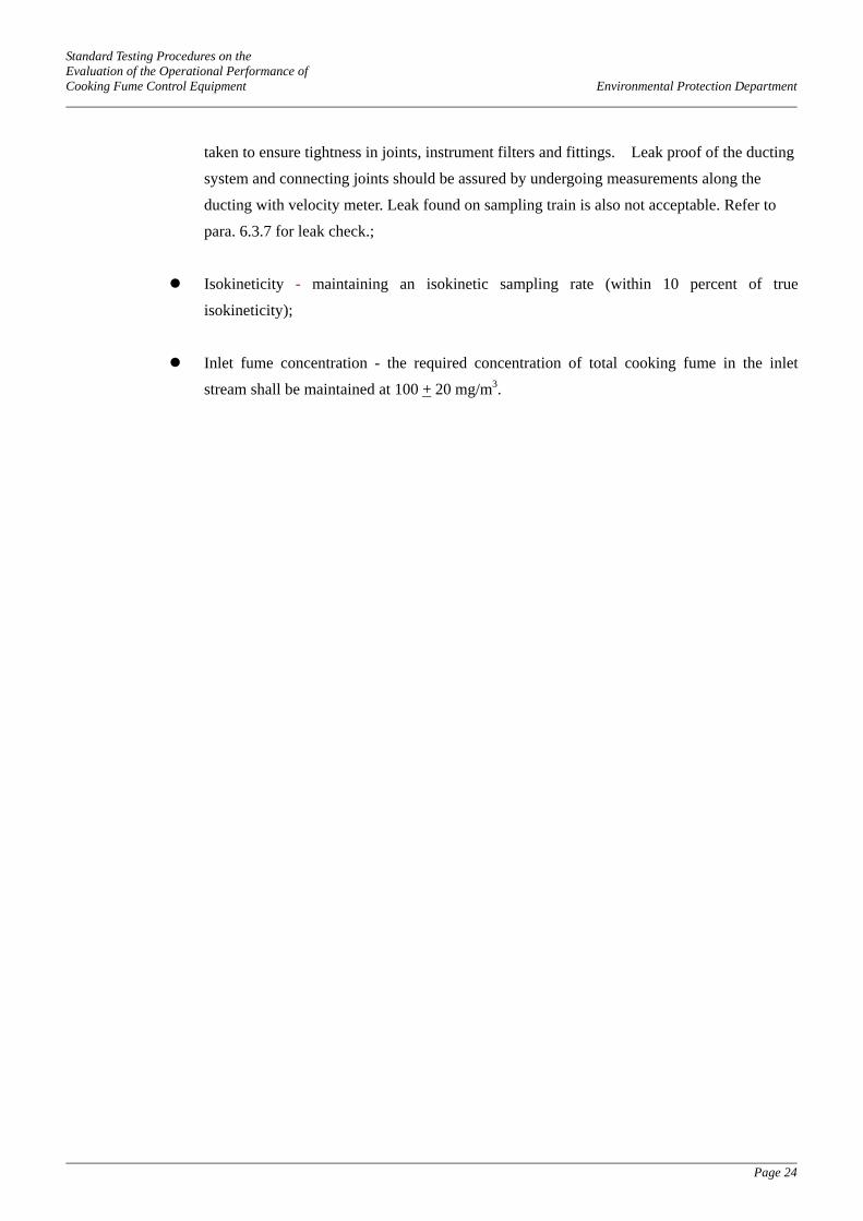
Standard Testing Procedures on the Evaluation of the Operational Performance of Cooking Fume Control Equipment Environmental Protection Department
Page 24
taken to ensure tightness in joints, instrument filters and fittings. Leak proof of the ducting
system and connecting joints should be assured by undergoing measurements along the
ducting with velocity meter. Leak found on sampling train is also not acceptable. Refer to
para. 6.3.7 for leak check.;
Isokineticity - maintaining an isokinetic sampling rate (within 10 percent of true
isokineticity);
Inlet fume concentration - the required concentration of total cooking fume in the inlet
stream shall be maintained at 100 + 20 mg/m3.

Standard Testing Procedures on the Evaluation of the Operational Performance of Cooking Fume Control Equipment Environmental Protection Department
Page 25
8 SAFETY PRECAUTIONS
8.1 Maintain adequate ventilation and supply of fresh air. Since the test system extracts large volume of air
inside the laboratory, sufficient ventilation and supply of fresh air should be adequately maintained.
Open the doors and use of mechanical fan whenever necessary.
8.2 It is important to make sure that the edge of the stove is so designed that there will be no naked flame
coming out from the gap between the wok and the gas-fired stove to avoid fire hazard. The internal rim
of the stove should be constructed in such a way that the wok sits squarely on it without any gap so that
there will be no naked flame coming out from below the wok.
8.3 LPG / Town Gas fired stove shall be handled with extreme care. When the stove is being operated, the
oil in woks can be heated up to a very high temperature. The cooking stove may cause fire especially
the scene is fraught with flammable cooking oil and LPG / Town Gas containers. Wear heat proof
gloves when handling the gas stoves.
8.4 When the oil generation system is being operated, dense cooking fume and high temperature oil droplets
are generated continuously. Such cooking fume and oil droplets may cause severe burns. Do not put
the hands inside the cooking fume generation chamber when it is in operation unless sufficient
protective clothing and gloves are worn.
8.5 Heat resisting thermometer must be inserted into the oil bath thoughout the test. During the generation
of oily fume, the burners must be manually controlled and adjusted to maintain the bulk oil temperature
in woks STRICTLY below 310°C.
8.6 Cooking oil may burn when the bulk oil temperature is higher than the fire point. Must handle oil bath
with care to avoid fire hazards.
8.7 Sufficient safety equipment shall be available in the testing laboratory. Safety equipment shall include
but not limited to the following (fire extinguisher, first aid box, etc) :
Fire blanket
Fire extinguishers (carbon dioxide type and/or dry powder type)
Fire alarm
Cotton gloves and heat proof gloves
Protective clothing and lab gown
Eye goggles
Waste oil container
First aid box

Standard Testing Procedures on the Evaluation of the Operational Performance of Cooking Fume Control Equipment Environmental Protection Department
Page 26
8.8 Some cooking fume control equipment may require water supply, properly manage the wastewater
discharge, and avoid wetting the floor which may be slippery. Wastewater may contain residue
cooking oil, such residual oil and other waste oil should be treated as chemical waste and handled
properly. Do not discharge waste oil to toilet or other improper drainage.
8.9 Maintain good housekeeping of the laboratory to avoid potential accidents.
8.10 Perchloroethylene is a suspected carcinogen. Handling of the solvent shall be inside a fume cupboard
or at a well ventilated area to avoid accumulation of high concentration of perchloroethylene vapour.
8.11 Analyzed sample extracts and waste perchloroethylene shall be handled properly and treated as
chemical waste.
8.12 Safety Training shall be provided to technical staff and laboratory staff to raise the awareness of safety.
The safety training shall include but not limited to the following :
- instruction on using safety equipment
- procedures in case of accident and fire
- potential hazards of the testing system and the testing procedures
- proper handling of waste oil, wastewater and chemical waste
- use of protective facilities

Standard Testing Procedures on the Evaluation of the Operational Performance of Cooking Fume Control Equipment Environmental Protection Department
Page 27
9 REFERENCES
i. USEPA Method 5 “Determination of Particulate Matters Emissions from Stationary Sources”, USEPA ii. PRC National Standard “Emission Standard of Cooking Fume” (中國國家標準 GB 18483-2001 – 飲
食業油煙排放標準)
iii. Report on Survey of Restaurant Emission of Cooking Fume Emissions from Local Restaurants, EPD .
iv. Report on Literature Survey of Legislative Control and Testing Method of Cooking Fume Control
Equipment for Cooking Fume Emission Control, EPD
v. USEPA Method 2 “Determination of Stack Gas Velocity and Volumetric Flow Rate”, USEPA
vi. Quality Assurance Handbook of Air Pollution Measurement System, Volume III, Stationary Sources
Specific Methods, USEPA
vii. USEPA Method 1 “Sample and Velocity Transverses for Stationary Sources”, USEPA
viii. Report of Study on Evaluation of Cooking Fume Emission Characteristics, EPD